EP3289898A1 - Atomizer and electronic cigarette having same - Google Patents
Atomizer and electronic cigarette having same Download PDFInfo
- Publication number
- EP3289898A1 EP3289898A1 EP17203162.7A EP17203162A EP3289898A1 EP 3289898 A1 EP3289898 A1 EP 3289898A1 EP 17203162 A EP17203162 A EP 17203162A EP 3289898 A1 EP3289898 A1 EP 3289898A1
- Authority
- EP
- European Patent Office
- Prior art keywords
- liquid
- atomizer
- heating
- liquid guiding
- sheets
- Prior art date
- Legal status (The legal status is an assumption and is not a legal conclusion. Google has not performed a legal analysis and makes no representation as to the accuracy of the status listed.)
- Granted
Links
Images



Classifications
-
- A—HUMAN NECESSITIES
- A24—TOBACCO; CIGARS; CIGARETTES; SIMULATED SMOKING DEVICES; SMOKERS' REQUISITES
- A24F—SMOKERS' REQUISITES; MATCH BOXES; SIMULATED SMOKING DEVICES
- A24F40/00—Electrically operated smoking devices; Component parts thereof; Manufacture thereof; Maintenance or testing thereof; Charging means specially adapted therefor
- A24F40/40—Constructional details, e.g. connection of cartridges and battery parts
- A24F40/46—Shape or structure of electric heating means
-
- A—HUMAN NECESSITIES
- A24—TOBACCO; CIGARS; CIGARETTES; SIMULATED SMOKING DEVICES; SMOKERS' REQUISITES
- A24F—SMOKERS' REQUISITES; MATCH BOXES; SIMULATED SMOKING DEVICES
- A24F40/00—Electrically operated smoking devices; Component parts thereof; Manufacture thereof; Maintenance or testing thereof; Charging means specially adapted therefor
- A24F40/40—Constructional details, e.g. connection of cartridges and battery parts
- A24F40/44—Wicks
-
- A—HUMAN NECESSITIES
- A61—MEDICAL OR VETERINARY SCIENCE; HYGIENE
- A61M—DEVICES FOR INTRODUCING MEDIA INTO, OR ONTO, THE BODY; DEVICES FOR TRANSDUCING BODY MEDIA OR FOR TAKING MEDIA FROM THE BODY; DEVICES FOR PRODUCING OR ENDING SLEEP OR STUPOR
- A61M11/00—Sprayers or atomisers specially adapted for therapeutic purposes
- A61M11/04—Sprayers or atomisers specially adapted for therapeutic purposes operated by the vapour pressure of the liquid to be sprayed or atomised
- A61M11/041—Sprayers or atomisers specially adapted for therapeutic purposes operated by the vapour pressure of the liquid to be sprayed or atomised using heaters
- A61M11/042—Sprayers or atomisers specially adapted for therapeutic purposes operated by the vapour pressure of the liquid to be sprayed or atomised using heaters electrical
-
- A—HUMAN NECESSITIES
- A24—TOBACCO; CIGARS; CIGARETTES; SIMULATED SMOKING DEVICES; SMOKERS' REQUISITES
- A24F—SMOKERS' REQUISITES; MATCH BOXES; SIMULATED SMOKING DEVICES
- A24F40/00—Electrically operated smoking devices; Component parts thereof; Manufacture thereof; Maintenance or testing thereof; Charging means specially adapted therefor
- A24F40/10—Devices using liquid inhalable precursors
-
- A—HUMAN NECESSITIES
- A24—TOBACCO; CIGARS; CIGARETTES; SIMULATED SMOKING DEVICES; SMOKERS' REQUISITES
- A24F—SMOKERS' REQUISITES; MATCH BOXES; SIMULATED SMOKING DEVICES
- A24F40/00—Electrically operated smoking devices; Component parts thereof; Manufacture thereof; Maintenance or testing thereof; Charging means specially adapted therefor
- A24F40/40—Constructional details, e.g. connection of cartridges and battery parts
- A24F40/48—Fluid transfer means, e.g. pumps
- A24F40/485—Valves; Apertures
Definitions
- the utility model relates to the field of electronic cigarettes, in particular to an atomizer and a split-type electronic cigarette including the atomizer.
- the atomizer As an alternative to traditional cigarettes, electronic cigarettes have the advantage of environmental protection and health and are gradually accepted by consumers at home and abroad.
- the atomizer has the function of storing a certain amount of tobacco liquid and atomizing the tobacco liquid to form an aerosol for suctioning.
- a typical atomizer in the prior art is to install an atomizing head in the liquid storage chamber, and the atomizing head is complicated in structure and costly.
- the heating element in the existing atomizing head adopts a spiral heating wire, which has a low heating efficiency, a poor atomizing effect and an unstable aerosol volume.
- the technical problem to be solved by the utility model is to overcome the shortcomings of the prior art and to provide an atomizer and a split-type electronic cigarette with a simple structure and a high heating efficiency.
- the utility model provides an atomizer, including: a housing having a mouthpiece thereon; a liquid storage cup provided in the housing and configured for storing tobacco liquid, the liquid storage cup having an opening at one end thereof; a microporous liquid conducting body plugged inside the opening and configured for conveying the tobacco liquid in the liquid storage cup to the atomizing unit; an atomizing unit connected to the opening and configured for heating the tobacco liquid to generate aerosol; and an air flow channel provided between the mouthpiece and the atomizing unit; wherein the atomizing unit includes a support, a liquid guiding component located in the support, and at least one vertically arranged heating sheet; the heating sheet includes a side surface in contact with the liquid guiding component, the liquid guiding component is configured to be in contact with the microporous liquid conducting body to guide the tobacco liquid to the heating sheet, and the support further defines an aerosol outlet configured for discharging the aerosol into the air flow channel.
- the liquid guiding component includes a first liquid guiding piece placed horizontally and a second liquid guiding piece placed vertically, the second liquid guiding piece includes a side surface attached to the heating sheet, and the first liquid guiding piece is located between the second liquid guiding piece and the microporous liquid conducting body and is horizontally attached to a bottom surface of the microporous liquid conducting body.
- the microporous liquid conducting body is made of PE foam material and/or PET fiber, and both the first liquid guiding piece and the second liquid guiding piece are made of non-woven fabrics material.
- the atomizer includes two heating sheets vertically arranged inside the support, the two heating sheets are spaced apart from each other, and each of the heating sheets matches with a correspondent one of the second liquid guiding pieces.
- the aerosol outlet is defined at a bottom of the support, and the aerosol outlet is aligned with the two heating sheets.
- a heating chamber is provided in the support, two card slots are formed on the inner wall of the heating chamber into which the heating sheets are inserted, and two of the second liquid guiding pieces are provided in the heating chamber, respectively, and are in contact with the corresponding heating sheets.
- the support is further provided with two electrode sheets, respectively, which are in contact with the pins of the heating sheets, and the electrode sheets include a contact part configured to be in contact with an electrode terminal of the power supply and a bending part configured for inserting into the support to fix the electrode sheets.
- a base is mounted in the housing, wherein the base is configured for fixing the atomizing device, the base defines two jacks aligned with the electrode sheets, and the jacks are adapted to be inserted by electrode terminals of a power supply to come into contact with the electrode sheets.
- the air flow channel has a size which gradually decreases from downstream to upstream, and has an air flow outlet defined between the housing and the liquid storage cup at an upstream position thereof, and the air flow outlet is communicated with the air flow channel and the mouthpiece.
- the heating sheet is a grid-shaped heating sheet or a mesh-shaped heating sheet.
- the utility model also provides a split-type electronic cigarette including: atomizer described above; and a power supply assembly detachably connected with the atomizer, wherein the power supply assembly includes a pair of electrode terminals, and the two electrode terminals are configured for electrically connecting to the heating sheet when the power supply assembly is connected to the atomizer.
- the atomizer and the power supply assembly are connected in a snap fit manner
- the housing includes an annular rib in an inner edge of a lower end of the housing of the atomizer, and the annular rib is configured for forming a snap fit connection.
- the liquid storage cup provided in the atomizer of the present invention is disposed inside the housing and may be integrally formed with the housing.
- the microporous liquid conducting body and the atomizing unit are disposed at the opening of the liquid storage cup, which is simple in structure and low in manufacturing cost.
- the atomizing unit adopts the design of the heating element, the heating element is vertically arranged and has a side surface in contact with the liquid guiding component, which may increase the contact area with the liquid guiding component, improve the heating efficiency, and have a good atomizing effect and a good aerosol volume stability.
- the present embodiment provides an atomizer 100 including a housing 101 and a liquid storage cup 103 disposed in the housing 101, an atomizing unit 200, a microporous liquid-conducting body 105, and an air flow channel 108.
- the housing 101 has a mouthpiece 102 at the top.
- An air flow channel 108 is provided between the mouthpiece 102 and the atomizing unit 200, and is configured for discharging the aerosol generated in the atomizing unit 200 to the outside of the mouthpiece 102.
- the liquid storage cup 103 is configured for storing the tobacco liquid, which may be disposable or reusable.
- the liquid storage cup 103 and the housing 101 are integrally formed. It is to be understood that the liquid storage cup 103 may also be detachably mounted inside the housing 101.
- An opening 104 is provided at one end of the liquid storage cup 103.
- the microporous liquid conducting body 105 is plugged inside the opening 104 and is configured for conveying the tobacco liquid in the liquid storage cup 103 to the atomizing unit 200.
- the atomizing unit 200 is connected to the opening 104 and is located below the microporous liquid conducting body 105.
- the above atomizing unit 200 includes a support 201, a liquid guiding component located in the support 201, and at least one vertically arranged heating sheet 204.
- the heating sheet 204 includes a side surface in contact with the liquid guiding component.
- the liquid guiding component is configured to be in contact with the microporous liquid conducting body 105 to guide the tobacco liquid to the heating sheet 204.
- the support 201 further defines an aerosol outlet 2011 configured for discharging the aerosol into the air flow channel 108.
- the heating sheet 204 is grid-shaped heating sheet or a mesh-shaped heating sheet.
- the heating sheet 204 has a side surface in contact with the liquid guiding component as a whole and has a large heating area and a high thermal efficiency.
- the atomizing unit 200 is assembled in the opening 104 of the liquid storage cup 103 as a whole, and the structure is simple.
- the liquid guiding component includes a first liquid guiding piece 202 placed horizontally and a second liquid guiding piece 203 placed vertically, the second liquid guiding piece 203 includes a side surface attached to the heating sheet 204, and the first liquid guiding piece 202 is located between the second liquid guiding piece 203 and the microporous liquid conducting body 105 and is horizontally attached to a bottom surface of the microporous liquid conducting body 105.
- the microporous liquid conducting body 105, the first liquid guiding piece 202 and the second liquid guiding piece 203 form a three-level liquid guiding structure.
- the tobacco liquid in the liquid storage cup 103 passes through the microporous liquid conducting body 105, the first liquid guiding piece 202 and the second liquid guiding piece 203, and finally reaches the heating sheet 204, which may prevent the tobacco liquid from being conveyed too fast so as to cause leakage.
- the conducting speed of the microporous liquid conducting body 105 is faster, but the capability of high temperature resistance is poorer.
- the first liquid guiding piece 202 and the second liquid guiding piece 203 may resist a high temperature, may be in direct contact with the heating sheet 204, and also may save a certain amount of tobacco liquid to be gradually supplied to the heating element 204, so that the amount of aerosol generated by heating is constantly uniform.
- the microporous liquid conducting body is made of PE foam material and/or PET fiber (polyester fiber), and in the present embodiment, it is made of synthetic porous material using PE foam material and PET fiber.
- Both the first liquid guiding piece and the second liquid guiding piece are made of non-woven fabrics material, and are in particular formed by laminating a plurality of non-woven fabrics.
- the non-woven fabrics may resist a high temperature and is suitable for direct contact with the heating element 104.
- two heating sheets 204 are vertically arranged inside the support 201, the two heating sheets are spaced apart from each other, and each of the heating sheets 204 matches with a correspondent one of the second liquid guiding pieces 203.
- the aerosol outlet 2011 is defined at a bottom of the support 201, and the aerosol outlet 2011 is aligned with the two heating sheets 204. Because there is a gap between the two heating elements 204 and the gap is in direct alignment and communication with the lower aerosol outlet 2011, two of the second liquid guiding pieces 203 are respectively distributed on two sides so as to facilitate the aerosol to be promptly discharged into the air flow channel 108. It is to be understood that, in order to increase the amount of aerosol in the atomizing unit 200, more heating sheets may be disposed in the support 201.
- a heating chamber 2013 is provided in the support 201, and two card slots 2012 are formed on the inner wall of the heating chamber 2013 into which the heating sheets 204 are inserted.
- Two of the second liquid guiding pieces 203 are provided in the heating chamber 2013, respectively, and are in contact with the corresponding heating sheets 204. In this way, the installation of the atomizing unit 200 is simplified.
- the first liquid guiding piece 202 is placed on the upper part of the heating chamber 2013.
- the support 201 is assembled at the opening end of the liquid storage cup 103.
- the support 201 is further provided with two electrode sheets 205, respectively, which are in contact with the pins of the heating sheets 204, and the electrode sheets include a contact part 2051 configured to be in contact with an electrode terminal of the power supply and a bending part 2052 configured for inserting into the support 201 to fix the electrode sheets 205.
- the pin of the heating sheet 204 passes through the bottom of the support 201, and then the electrode sheet 205 is mounted on the support 201 and the pin of the heating sheet 204 is compressed.
- One end of the two electrode sheets 205 is connected to one electrode sheet 205 at the same time, and the other end of the two electrode sheets 205 is connected to another electrode sheet 205.
- a base 106 is further mounted in the housing 101, the base is configured for fixing the atomizing device 200, the base 106 defines two jacks 1061 aligned with the electrode sheets, and the jacks 1061 are adapted to be inserted by electrode terminals of a power supply to come into contact with the electrode sheets 205 to provide power to the heating element 204.
- the airflow channel 108 has a size which gradually decreases from downstream to upstream, and has an airflow outlet 109 defined between the housing 101 and the liquid storage cup 103 at an upstream position thereof, and the air flow outlet 109 is communicated with the air flow channel 108 and the mouthpiece 102.
- the aperture of the airflow outlet 109 is generally smaller.
- the design that the air flow channel is gradually smaller may allow the air flow to be buffered, and may be conducive for larger droplets in the aerosol to be condensed and flow back to the atomizing unit 200 underneath.
- the present embodiment further provides a split-type electronic cigarette 400, including the atomizer 100 described above and a power supply assembly 300 detachably connected to the atomizer 100.
- the power supply assembly 300 includes an internal battery 301 and a pair of electrode terminals 302, and the two electrode terminals 302 pass through the jacks 1061 described above and are electrically connected to the heating sheet 204 when the power supply assembly 300 is connected to the atomizer 100.
- the atomizer 100 and the power supply assembly 300 are connected in a snap fit manner, and an annular rib 107 is provided in an inner edge of a lower end of the housing 101 of the atomizer 100.
- the atomizer 100 and the power supply assembly 300 may be connected in a manner of a common thread, a rotary buckle, a magnetic attraction, and the like.
Landscapes
- Health & Medical Sciences (AREA)
- Engineering & Computer Science (AREA)
- Anesthesiology (AREA)
- Biomedical Technology (AREA)
- Heart & Thoracic Surgery (AREA)
- Hematology (AREA)
- Life Sciences & Earth Sciences (AREA)
- Animal Behavior & Ethology (AREA)
- General Health & Medical Sciences (AREA)
- Public Health (AREA)
- Veterinary Medicine (AREA)
- Electrostatic Spraying Apparatus (AREA)
Abstract
Description
- The utility model relates to the field of electronic cigarettes, in particular to an atomizer and a split-type electronic cigarette including the atomizer.
- As an alternative to traditional cigarettes, electronic cigarettes have the advantage of environmental protection and health and are gradually accepted by consumers at home and abroad. As a main component of electronic cigarettes, the atomizer has the function of storing a certain amount of tobacco liquid and atomizing the tobacco liquid to form an aerosol for suctioning. At present, a typical atomizer in the prior art is to install an atomizing head in the liquid storage chamber, and the atomizing head is complicated in structure and costly. Under the trend of electronic cigarettes becoming more and more simple and portable, it is necessary to design an atomizer which is simple in structure and convenient to carrying and has a disposable liquid storage cup which is easy to replace. At the same time, the heating element in the existing atomizing head adopts a spiral heating wire, which has a low heating efficiency, a poor atomizing effect and an unstable aerosol volume.
- The technical problem to be solved by the utility model is to overcome the shortcomings of the prior art and to provide an atomizer and a split-type electronic cigarette with a simple structure and a high heating efficiency.
- In order to solve the above technical problem, the utility model provides an atomizer, including: a housing having a mouthpiece thereon; a liquid storage cup provided in the housing and configured for storing tobacco liquid, the liquid storage cup having an opening at one end thereof; a microporous liquid conducting body plugged inside the opening and configured for conveying the tobacco liquid in the liquid storage cup to the atomizing unit; an atomizing unit connected to the opening and configured for heating the tobacco liquid to generate aerosol; and an air flow channel provided between the mouthpiece and the atomizing unit; wherein the atomizing unit includes a support, a liquid guiding component located in the support, and at least one vertically arranged heating sheet; the heating sheet includes a side surface in contact with the liquid guiding component, the liquid guiding component is configured to be in contact with the microporous liquid conducting body to guide the tobacco liquid to the heating sheet, and the support further defines an aerosol outlet configured for discharging the aerosol into the air flow channel.
- Further, the liquid guiding component includes a first liquid guiding piece placed horizontally and a second liquid guiding piece placed vertically, the second liquid guiding piece includes a side surface attached to the heating sheet, and the first liquid guiding piece is located between the second liquid guiding piece and the microporous liquid conducting body and is horizontally attached to a bottom surface of the microporous liquid conducting body.
- Quite usefully, the microporous liquid conducting body is made of PE foam material and/or PET fiber, and both the first liquid guiding piece and the second liquid guiding piece are made of non-woven fabrics material.
- As one of the specific embodiments, the atomizer includes two heating sheets vertically arranged inside the support, the two heating sheets are spaced apart from each other, and each of the heating sheets matches with a correspondent one of the second liquid guiding pieces.
- Further, the aerosol outlet is defined at a bottom of the support, and the aerosol outlet is aligned with the two heating sheets.
- Further, a heating chamber is provided in the support, two card slots are formed on the inner wall of the heating chamber into which the heating sheets are inserted, and two of the second liquid guiding pieces are provided in the heating chamber, respectively, and are in contact with the corresponding heating sheets.
- Further, the support is further provided with two electrode sheets, respectively, which are in contact with the pins of the heating sheets, and the electrode sheets include a contact part configured to be in contact with an electrode terminal of the power supply and a bending part configured for inserting into the support to fix the electrode sheets.
- Further, a base is mounted in the housing, wherein the base is configured for fixing the atomizing device, the base defines two jacks aligned with the electrode sheets, and the jacks are adapted to be inserted by electrode terminals of a power supply to come into contact with the electrode sheets.
- Quite usefully, the air flow channel has a size which gradually decreases from downstream to upstream, and has an air flow outlet defined between the housing and the liquid storage cup at an upstream position thereof, and the air flow outlet is communicated with the air flow channel and the mouthpiece.
- Quite usefully, the heating sheet is a grid-shaped heating sheet or a mesh-shaped heating sheet.
- The utility model also provides a split-type electronic cigarette including: atomizer described above; and a power supply assembly detachably connected with the atomizer, wherein the power supply assembly includes a pair of electrode terminals, and the two electrode terminals are configured for electrically connecting to the heating sheet when the power supply assembly is connected to the atomizer.
- As a preferred solution, the atomizer and the power supply assembly are connected in a snap fit manner, the housing includes an annular rib in an inner edge of a lower end of the housing of the atomizer, and the annular rib is configured for forming a snap fit connection.
- The beneficial effects of the utility model are mainly as follows: the liquid storage cup provided in the atomizer of the present invention is disposed inside the housing and may be integrally formed with the housing. The microporous liquid conducting body and the atomizing unit are disposed at the opening of the liquid storage cup, which is simple in structure and low in manufacturing cost. In addition, the atomizing unit adopts the design of the heating element, the heating element is vertically arranged and has a side surface in contact with the liquid guiding component, which may increase the contact area with the liquid guiding component, improve the heating efficiency, and have a good atomizing effect and a good aerosol volume stability.
-
-
FIG. 1 is an axial cross-sectional view of an atomizer provided in an embodiment. -
FIG. 2 is an axial sectional view of an atomizer in another cross section in an embodiment. -
FIG. 3 is a schematic structural view of an atomizing unit involved in an embodiment. -
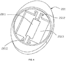
FIG. 4 is a schematic structural view of a support in an embodiment. -
FIG. 5 is a schematic structural view of an electronic cigarette provided in an embodiment. - The specific structure of the atomizer and the split-type electronic cigarette and the principle of using the same will be further elaborated below with specific embodiments.
- Referring to
FIG. 1 andFIG. 2 , the present embodiment provides anatomizer 100 including ahousing 101 and aliquid storage cup 103 disposed in thehousing 101, anatomizing unit 200, a microporous liquid-conductingbody 105, and anair flow channel 108. Thehousing 101 has amouthpiece 102 at the top. Anair flow channel 108 is provided between themouthpiece 102 and theatomizing unit 200, and is configured for discharging the aerosol generated in theatomizing unit 200 to the outside of themouthpiece 102. - The
liquid storage cup 103 is configured for storing the tobacco liquid, which may be disposable or reusable. In the present embodiment, theliquid storage cup 103 and thehousing 101 are integrally formed. It is to be understood that theliquid storage cup 103 may also be detachably mounted inside thehousing 101. Anopening 104 is provided at one end of theliquid storage cup 103. The microporousliquid conducting body 105 is plugged inside theopening 104 and is configured for conveying the tobacco liquid in theliquid storage cup 103 to theatomizing unit 200. Theatomizing unit 200 is connected to theopening 104 and is located below the microporousliquid conducting body 105. - The
above atomizing unit 200 includes asupport 201, a liquid guiding component located in thesupport 201, and at least one vertically arrangedheating sheet 204. Theheating sheet 204 includes a side surface in contact with the liquid guiding component. The liquid guiding component is configured to be in contact with the microporousliquid conducting body 105 to guide the tobacco liquid to theheating sheet 204. Thesupport 201 further defines anaerosol outlet 2011 configured for discharging the aerosol into theair flow channel 108. Quite usefully, in the present embodiment, theheating sheet 204 is grid-shaped heating sheet or a mesh-shaped heating sheet. Theheating sheet 204 has a side surface in contact with the liquid guiding component as a whole and has a large heating area and a high thermal efficiency. Theatomizing unit 200 is assembled in theopening 104 of theliquid storage cup 103 as a whole, and the structure is simple. - Quite usefully, in the present embodiment, the liquid guiding component includes a first
liquid guiding piece 202 placed horizontally and a secondliquid guiding piece 203 placed vertically, the secondliquid guiding piece 203 includes a side surface attached to theheating sheet 204, and the firstliquid guiding piece 202 is located between the secondliquid guiding piece 203 and the microporousliquid conducting body 105 and is horizontally attached to a bottom surface of the microporousliquid conducting body 105. The microporousliquid conducting body 105, the firstliquid guiding piece 202 and the secondliquid guiding piece 203 form a three-level liquid guiding structure. The tobacco liquid in theliquid storage cup 103 passes through the microporousliquid conducting body 105, the firstliquid guiding piece 202 and the secondliquid guiding piece 203, and finally reaches theheating sheet 204, which may prevent the tobacco liquid from being conveyed too fast so as to cause leakage. - The conducting speed of the microporous
liquid conducting body 105 is faster, but the capability of high temperature resistance is poorer. The firstliquid guiding piece 202 and the second liquid guiding piece 203 (that is, the liquid guiding component) may resist a high temperature, may be in direct contact with theheating sheet 204, and also may save a certain amount of tobacco liquid to be gradually supplied to theheating element 204, so that the amount of aerosol generated by heating is constantly uniform. As a preferred mode, the microporous liquid conducting body is made of PE foam material and/or PET fiber (polyester fiber), and in the present embodiment, it is made of synthetic porous material using PE foam material and PET fiber. Both the first liquid guiding piece and the second liquid guiding piece are made of non-woven fabrics material, and are in particular formed by laminating a plurality of non-woven fabrics. The non-woven fabrics may resist a high temperature and is suitable for direct contact with theheating element 104. - As shown in combination with
FIG. 1 ,FIG. 3 , andFIG. 4 , twoheating sheets 204 are vertically arranged inside thesupport 201, the two heating sheets are spaced apart from each other, and each of theheating sheets 204 matches with a correspondent one of the secondliquid guiding pieces 203. Theaerosol outlet 2011 is defined at a bottom of thesupport 201, and theaerosol outlet 2011 is aligned with the twoheating sheets 204. Because there is a gap between the twoheating elements 204 and the gap is in direct alignment and communication with thelower aerosol outlet 2011, two of the secondliquid guiding pieces 203 are respectively distributed on two sides so as to facilitate the aerosol to be promptly discharged into theair flow channel 108. It is to be understood that, in order to increase the amount of aerosol in theatomizing unit 200, more heating sheets may be disposed in thesupport 201. - As shown in
FIG. 4 , aheating chamber 2013 is provided in thesupport 201, and twocard slots 2012 are formed on the inner wall of theheating chamber 2013 into which theheating sheets 204 are inserted. Two of the secondliquid guiding pieces 203 are provided in theheating chamber 2013, respectively, and are in contact with thecorresponding heating sheets 204. In this way, the installation of theatomizing unit 200 is simplified. After the secondliquid guiding piece 203 and theheating element 204 are mounted in theheating chamber 2013, the firstliquid guiding piece 202 is placed on the upper part of theheating chamber 2013. Finally, thesupport 201 is assembled at the opening end of theliquid storage cup 103. - Referring to
FIG. 2 again, thesupport 201 is further provided with twoelectrode sheets 205, respectively, which are in contact with the pins of theheating sheets 204, and the electrode sheets include acontact part 2051 configured to be in contact with an electrode terminal of the power supply and abending part 2052 configured for inserting into thesupport 201 to fix theelectrode sheets 205. During assembly, the pin of theheating sheet 204 passes through the bottom of thesupport 201, and then theelectrode sheet 205 is mounted on thesupport 201 and the pin of theheating sheet 204 is compressed. One end of the twoelectrode sheets 205 is connected to oneelectrode sheet 205 at the same time, and the other end of the twoelectrode sheets 205 is connected to anotherelectrode sheet 205. - Quite usefully, a
base 106 is further mounted in thehousing 101, the base is configured for fixing theatomizing device 200, thebase 106 defines twojacks 1061 aligned with the electrode sheets, and thejacks 1061 are adapted to be inserted by electrode terminals of a power supply to come into contact with theelectrode sheets 205 to provide power to theheating element 204. - As a preferred solution of the present embodiment, the
airflow channel 108 has a size which gradually decreases from downstream to upstream, and has anairflow outlet 109 defined between thehousing 101 and theliquid storage cup 103 at an upstream position thereof, and theair flow outlet 109 is communicated with theair flow channel 108 and themouthpiece 102. The aperture of theairflow outlet 109 is generally smaller. The design that the air flow channel is gradually smaller may allow the air flow to be buffered, and may be conducive for larger droplets in the aerosol to be condensed and flow back to theatomizing unit 200 underneath. - Referring to
FIG. 5 , the present embodiment further provides a split-typeelectronic cigarette 400, including theatomizer 100 described above and apower supply assembly 300 detachably connected to theatomizer 100. Thepower supply assembly 300 includes aninternal battery 301 and a pair ofelectrode terminals 302, and the twoelectrode terminals 302 pass through thejacks 1061 described above and are electrically connected to theheating sheet 204 when thepower supply assembly 300 is connected to theatomizer 100. - As a preferred solution in the present embodiment, the
atomizer 100 and thepower supply assembly 300 are connected in a snap fit manner, and anannular rib 107 is provided in an inner edge of a lower end of thehousing 101 of theatomizer 100. Of course, It is to be understood that theatomizer 100 and thepower supply assembly 300 may be connected in a manner of a common thread, a rotary buckle, a magnetic attraction, and the like. - The above embodiments are only some embodiments of the utility model listed for the sake of easy understanding of the summary of the utility model, and are not intended to limit the technical solutions of the utility model, and not intended to be exhaustive of any possible implementation. Therefore, any minor improvements or equivalent substitutions made to the structures, the flows, or the steps of the utility model should be included in its scope of protection.
Claims (12)
- An atomizer, comprising:a housing having a mouthpiece thereon;a liquid storage cup provided in the housing and configured for storing tobacco liquid, the liquid storage cup having an opening at one end thereof;a microporous liquid conducting body plugged inside the opening;an atomizing unit connected to the opening and configured for heating the tobacco liquid to generate aerosol, the microporous liquid conducting body being configured for conveying the tobacco liquid in the liquid storage cup to the atomizing unit; andan air flow channel provided between the mouthpiece and the atomizing unit;wherein the atomizing unit comprises a support, a liquid guiding component located in the support, and at least one vertically arranged heating sheet; the heating sheet comprises a side surface in contact with the liquid guiding component, the liquid guiding component is configured to be in contact with the microporous liquid conducting body to guide the tobacco liquid to the heating sheet, and the support further defines an aerosol outlet configured for discharging the aerosol into the air flow channel.
- The atomizer according to claim 1, wherein the liquid guiding component comprises a first liquid guiding piece placed horizontally and a second liquid guiding piece placed vertically, the second liquid guiding piece comprises a side surface attached to the heating sheet, and the first liquid guiding piece is located between the second liquid guiding piece and the microporous liquid conducting body and is horizontally attached to a bottom surface of the microporous liquid conducting body.
- The atomizer according to claim 2, wherein the microporous liquid conducting body is made of PE foam material and/or PET fiber, and both the first liquid guiding piece and the second liquid guiding piece are made of non-woven fabrics material.
- The atomizer according to claim 2, wherein the atomizer comprises two heating sheets vertically arranged inside the support, the two heating sheets are spaced apart from each other, and each of the heating sheets matches with a correspondent one of the second liquid guiding pieces.
- The atomizer according to claim 4, wherein the aerosol outlet is defined at a bottom of the support, and the aerosol outlet is aligned with the two heating sheets.
- The atomizer according to claim 5, wherein a heating chamber is provided in the support, two card slots are formed on the inner wall of the heating chamber into which the heating sheets are inserted, and two of the second liquid guiding pieces are provided in the heating chamber, respectively, and are in contact with the corresponding heating sheets.
- The atomizer according to claim 1, wherein the support is further provided with two electrode sheets, respectively, which are in contact with the pins of the heating sheets, and the electrode sheets comprise a contact part configured to be in contact with an electrode terminal of the power supply and a bending part configured for inserting into the support to fix the electrode sheets.
- The atomizer according to claim 7, further comprising a base mounted in the housing, wherein the base is configured for fixing the atomizing device, the base defines two jacks aligned with the electrode sheets, and the jacks are adapted to be inserted by electrode terminals of a power supply to come into contact with the electrode sheets.
- The atomizer according to claim 1, wherein the air flow channel has a size which gradually decreases from downstream to upstream, and has an air flow outlet defined between the housing and the liquid storage cup at an upstream position thereof, and the air flow outlet is communicated with the air flow channel and the mouthpiece.
- The atomizer according to claim 1, wherein the heating sheet is a grid-shaped heating sheet or a mesh-shaped heating sheet.
- An electronic cigarette comprising:an atomizer; anda power supply assembly detachably connected with the atomizer,wherein the atomizer is the atomizer according to any one of claims 1 to 10, the power supply assembly comprises a pair of electrode terminals, and the two electrode terminals are configured for electrically connecting to the heating sheet when the power supply assembly is connected to the atomizer.
- The electronic cigarette according to claim 11, wherein the atomizer and the power supply assembly are connected in a snap fit manner, the housing comprises an annular rib in an inner edge of a lower end of the housing of the atomizer, and the annular rib is configured for forming a snap fit connection.
Applications Claiming Priority (1)
| Application Number | Priority Date | Filing Date | Title |
|---|---|---|---|
| CN201621266920.9U CN206403199U (en) | 2016-11-24 | 2016-11-24 | Atomizer and separated electronic cigarette |
Publications (2)
| Publication Number | Publication Date |
|---|---|
| EP3289898A1 true EP3289898A1 (en) | 2018-03-07 |
| EP3289898B1 EP3289898B1 (en) | 2021-10-20 |
Family
ID=59547862
Family Applications (1)
| Application Number | Title | Priority Date | Filing Date |
|---|---|---|---|
| EP17203162.7A Active EP3289898B1 (en) | 2016-11-24 | 2017-11-22 | Atomizer and electronic cigarette having same |
Country Status (3)
| Country | Link |
|---|---|
| US (1) | US10375997B2 (en) |
| EP (1) | EP3289898B1 (en) |
| CN (1) | CN206403199U (en) |
Cited By (2)
| Publication number | Priority date | Publication date | Assignee | Title |
|---|---|---|---|---|
| US11452826B2 (en) | 2016-03-24 | 2022-09-27 | Nicoventures Trading Limited | Mechanical connector for electronic vapor provision system |
| EP3903610A4 (en) * | 2018-12-26 | 2022-12-28 | Changzhou Patent Electronic Technology Co., Ltd | CARTRIDGE AND ELECTRONIC CIGARETTE |
Families Citing this family (36)
| Publication number | Priority date | Publication date | Assignee | Title |
|---|---|---|---|---|
| CN206403199U (en) * | 2016-11-24 | 2017-08-15 | 深圳市合元科技有限公司 | Atomizer and separated electronic cigarette |
| DE102017121664A1 (en) | 2017-09-19 | 2019-03-21 | Hauni Maschinenbau Gmbh | Component part and base part for an inhaler, and method for manufacturing the same |
| CN108158041B (en) * | 2018-01-18 | 2023-09-01 | 深圳市新宜康科技股份有限公司 | Atomization device with metal mesh and manufacturing method thereof |
| CN208490858U (en) * | 2018-07-11 | 2019-02-15 | 深圳市艾维普思科技有限公司 | Atomizer and electronic cigarette |
| US11678700B2 (en) | 2018-10-12 | 2023-06-20 | Rai Strategic Holdings, Inc. | Aerosol delivery device with visible indicator |
| US11502466B2 (en) | 2018-10-12 | 2022-11-15 | Rai Strategic Holdings, Inc. | Aerosol delivery device with improved connectivity, airflow, and aerosol paths |
| US11974603B2 (en) | 2018-10-12 | 2024-05-07 | Rai Strategic Holdings, Inc. | Aerosol delivery device with visible indicator |
| US12171261B2 (en) | 2018-10-12 | 2024-12-24 | Rai Strategic Holdings, Inc. | Vaporization system |
| US10791767B2 (en) | 2018-10-12 | 2020-10-06 | Rai Strategic Holdings, Inc. | Connectors for forming electrical and mechanical connections between interchangeable units in an aerosol delivery system |
| US10939702B2 (en) | 2018-10-12 | 2021-03-09 | Rai Strategic Holdings, Inc. | Connectors for forming electrical and mechanical connections between interchangeable units in an aerosol delivery system |
| US11291249B2 (en) | 2018-10-12 | 2022-04-05 | Rai Strategic Holdings, Inc. | Aerosol delivery device with visible indicator |
| US12232526B2 (en) | 2018-10-12 | 2025-02-25 | Rai Strategic Holdings, Inc. | Connectors for forming electrical and mechanical connections between interchangeable units in an aerosol delivery system |
| US12342860B2 (en) * | 2018-10-12 | 2025-07-01 | Rai Strategic Holdings, Inc. | Heater and liquid transport for an aerosol delivery system |
| US11156766B2 (en) | 2018-11-19 | 2021-10-26 | Rai Strategic Holdings, Inc. | Aerosol delivery device |
| US11372153B2 (en) | 2018-11-19 | 2022-06-28 | Rai Strategic Holdings, Inc. | Cartridge orientation for selection of a control function in a vaporization system |
| US11592793B2 (en) | 2018-11-19 | 2023-02-28 | Rai Strategic Holdings, Inc. | Power control for an aerosol delivery device |
| US11614720B2 (en) | 2018-11-19 | 2023-03-28 | Rai Strategic Holdings, Inc. | Temperature control in an aerosol delivery device |
| US12066654B2 (en) | 2018-11-19 | 2024-08-20 | Rai Strategic Holdings, Inc. | Charging control for an aerosol delivery device |
| CN111358058A (en) * | 2018-12-26 | 2020-07-03 | 常州市派腾电子技术服务有限公司 | Battery case, electronic cigarette and assembling method |
| USD895894S1 (en) * | 2019-10-24 | 2020-09-08 | Puff Corporation | Mouthpiece for a portable vaporizer |
| IL295018B2 (en) * | 2020-01-28 | 2026-01-01 | Philip Morris Products Sa | Heating element having heat conductive and wicking filaments |
| CN111135401B (en) * | 2020-02-19 | 2025-04-01 | 广州昊熹医疗科技有限公司 | A heating type spray atomization device |
| CN111374352B (en) * | 2020-04-08 | 2024-06-11 | 深圳市思源贝尔科技有限公司 | Electronic cigarette heating component and portable small-smoke electronic cigarette atomizer thereof |
| US11856986B2 (en) | 2020-10-19 | 2024-01-02 | Rai Strategic Holdings, Inc. | Customizable panel for aerosol delivery device |
| CN112237300A (en) * | 2020-11-24 | 2021-01-19 | 凡品思(深圳)科技有限公司 | Atomizing device and electron cigarette |
| CN112890301B (en) * | 2021-02-20 | 2025-08-29 | 深圳市华诚达精密工业有限公司 | Heating element, heating component and atomizing device with stable atomization |
| US12543784B2 (en) | 2021-03-24 | 2026-02-10 | Rai Strategic Holdings, Inc. | Aerosol delivery device |
| US20220378097A1 (en) * | 2021-05-28 | 2022-12-01 | Shenzhen Eigate Technology Co., Ltd. | Atomizer and electronic cigarette comprising the same |
| CN113876041A (en) * | 2021-09-22 | 2022-01-04 | 深圳市克莱鹏科技有限公司 | Heating sheet and electronic cigarette |
| CN113876042A (en) * | 2021-09-26 | 2022-01-04 | 深圳市克莱鹏科技有限公司 | Cigarette bullet and electron cigarette |
| US12144377B2 (en) | 2021-10-01 | 2024-11-19 | Rai Strategic Holdings, Inc. | Absorbent containing mouthpiece for aerosol delivery device |
| CN217284803U (en) * | 2021-12-08 | 2022-08-26 | 深圳市卓力能技术有限公司 | Atomizer and electronic atomization device |
| CN218474088U (en) * | 2022-01-30 | 2023-02-14 | 深圳市赛尔美电子科技有限公司 | Heating element, atomizer and electronic cigarette |
| CN114886164B (en) * | 2022-06-16 | 2025-07-18 | 深圳市赛尔美电子科技有限公司 | Atomization assembly, atomizer and aerosol generating device |
| CN117256957A (en) * | 2023-11-09 | 2023-12-22 | 深圳易佳特科技有限公司 | Atomizer core, atomizer, electronic cigarette and assembly method |
| WO2025097934A1 (en) * | 2023-11-09 | 2025-05-15 | 深圳易佳特科技有限公司 | Atomization core, atomizer and e-cigarette |
Citations (3)
| Publication number | Priority date | Publication date | Assignee | Title |
|---|---|---|---|---|
| US20140109921A1 (en) * | 2012-09-29 | 2014-04-24 | Shenzhen Smoore Technology Limited | Electronic cigarette |
| US20140299125A1 (en) * | 2008-10-23 | 2014-10-09 | Batmark Limited | Inhaler |
| CN205358219U (en) * | 2015-12-31 | 2016-07-06 | 深圳市合元科技有限公司 | The heating element , atomizer that contains this the heating element and electron cigarette |
Family Cites Families (2)
| Publication number | Priority date | Publication date | Assignee | Title |
|---|---|---|---|---|
| CN206403199U (en) * | 2016-11-24 | 2017-08-15 | 深圳市合元科技有限公司 | Atomizer and separated electronic cigarette |
| CN206808668U (en) * | 2017-03-31 | 2017-12-29 | 深圳市合元科技有限公司 | The atomizer and electronic cigarette of adjustable air inflow |
-
2016
- 2016-11-24 CN CN201621266920.9U patent/CN206403199U/en active Active
-
2017
- 2017-11-22 US US15/821,757 patent/US10375997B2/en active Active
- 2017-11-22 EP EP17203162.7A patent/EP3289898B1/en active Active
Patent Citations (4)
| Publication number | Priority date | Publication date | Assignee | Title |
|---|---|---|---|---|
| US20140299125A1 (en) * | 2008-10-23 | 2014-10-09 | Batmark Limited | Inhaler |
| US20140109921A1 (en) * | 2012-09-29 | 2014-04-24 | Shenzhen Smoore Technology Limited | Electronic cigarette |
| CN205358219U (en) * | 2015-12-31 | 2016-07-06 | 深圳市合元科技有限公司 | The heating element , atomizer that contains this the heating element and electron cigarette |
| US20170105454A1 (en) * | 2015-12-31 | 2017-04-20 | Shenzhen First Union Technology Co., Ltd. | Heating assembly, atomizer and electronic cigarette having same |
Cited By (3)
| Publication number | Priority date | Publication date | Assignee | Title |
|---|---|---|---|---|
| US11452826B2 (en) | 2016-03-24 | 2022-09-27 | Nicoventures Trading Limited | Mechanical connector for electronic vapor provision system |
| EP3903610A4 (en) * | 2018-12-26 | 2022-12-28 | Changzhou Patent Electronic Technology Co., Ltd | CARTRIDGE AND ELECTRONIC CIGARETTE |
| US12053023B2 (en) | 2018-12-26 | 2024-08-06 | Changzhou Patent Electronic Technology Co., LTD | Cartridge and electronic cigarette |
Also Published As
| Publication number | Publication date |
|---|---|
| US10375997B2 (en) | 2019-08-13 |
| EP3289898B1 (en) | 2021-10-20 |
| CN206403199U (en) | 2017-08-15 |
| US20180140019A1 (en) | 2018-05-24 |
Similar Documents
| Publication | Publication Date | Title |
|---|---|---|
| EP3289898B1 (en) | Atomizer and electronic cigarette having same | |
| CN206079041U (en) | Atomizer and including split type electron cigarette of this atomizer | |
| CN206403207U (en) | Atomizing cartridge and electronic cigarette | |
| CN114158772B (en) | Atomizer, electronic atomization device and liquid guiding mechanism | |
| EP4042886B1 (en) | Ultrasonic atomizer | |
| CN207912059U (en) | A kind of electronic cigarette of efficient oil resistance oil removal | |
| CN209768989U (en) | Atomizing device and electronic atomizing equipment | |
| CN215455369U (en) | Electronic cigarette with function of preventing smoke oil and condensate leakage | |
| CN109757779B (en) | Atomizing device, atomizer thereof and atomizing core | |
| CN206294891U (en) | Electronic cigarette | |
| CN219125369U (en) | Atomization device and electronic cigarette | |
| CN216019106U (en) | Atomizing core, atomizer and electronic atomization device | |
| CN117918578A (en) | Atomizer with flat liquid guiding layer | |
| CN210642446U (en) | Power supply assembly of electronic cigarette and electronic cigarette | |
| CN217771425U (en) | Atomizer and electronic atomization device | |
| CN212787424U (en) | Aerosol generating device | |
| CN218889286U (en) | Aerosol generating assembly and aerosol generating device | |
| CN217826745U (en) | Electronic atomization device and atomizer thereof | |
| CN206062137U (en) | Pen type oil-leakage-prevention electronic atomization device | |
| CN210124319U (en) | Atomizer and electronic cigarette | |
| CN111602864B (en) | Electronic cigarette power supply component and electronic cigarette | |
| CN220966416U (en) | An aerosol generating device | |
| CN221307267U (en) | Atomizer and electronic atomization device | |
| CN220831957U (en) | Atomizing device and electronic cigarette thereof | |
| CN221843845U (en) | Electronic cigarettes |
Legal Events
| Date | Code | Title | Description |
|---|---|---|---|
| PUAI | Public reference made under article 153(3) epc to a published international application that has entered the european phase |
Free format text: ORIGINAL CODE: 0009012 |
|
| STAA | Information on the status of an ep patent application or granted ep patent |
Free format text: STATUS: REQUEST FOR EXAMINATION WAS MADE |
|
| 17P | Request for examination filed |
Effective date: 20171219 |
|
| AK | Designated contracting states |
Kind code of ref document: A1 Designated state(s): AL AT BE BG CH CY CZ DE DK EE ES FI FR GB GR HR HU IE IS IT LI LT LU LV MC MK MT NL NO PL PT RO RS SE SI SK SM TR |
|
| AX | Request for extension of the european patent |
Extension state: BA ME |
|
| REG | Reference to a national code |
Ref country code: DE Ref legal event code: R079 Ref document number: 602017047822 Country of ref document: DE Free format text: PREVIOUS MAIN CLASS: A24F0047000000 Ipc: A24F0040440000 |
|
| GRAP | Despatch of communication of intention to grant a patent |
Free format text: ORIGINAL CODE: EPIDOSNIGR1 |
|
| STAA | Information on the status of an ep patent application or granted ep patent |
Free format text: STATUS: GRANT OF PATENT IS INTENDED |
|
| RIC1 | Information provided on ipc code assigned before grant |
Ipc: A24F 40/485 20200101ALN20210419BHEP Ipc: A24F 40/10 20200101ALN20210419BHEP Ipc: A24F 40/46 20200101ALI20210419BHEP Ipc: A24F 40/44 20200101AFI20210419BHEP |
|
| INTG | Intention to grant announced |
Effective date: 20210512 |
|
| GRAS | Grant fee paid |
Free format text: ORIGINAL CODE: EPIDOSNIGR3 |
|
| GRAA | (expected) grant |
Free format text: ORIGINAL CODE: 0009210 |
|
| STAA | Information on the status of an ep patent application or granted ep patent |
Free format text: STATUS: THE PATENT HAS BEEN GRANTED |
|
| AK | Designated contracting states |
Kind code of ref document: B1 Designated state(s): AL AT BE BG CH CY CZ DE DK EE ES FI FR GB GR HR HU IE IS IT LI LT LU LV MC MK MT NL NO PL PT RO RS SE SI SK SM TR |
|
| REG | Reference to a national code |
Ref country code: GB Ref legal event code: FG4D |
|
| REG | Reference to a national code |
Ref country code: CH Ref legal event code: EP |
|
| REG | Reference to a national code |
Ref country code: IE Ref legal event code: FG4D |
|
| REG | Reference to a national code |
Ref country code: DE Ref legal event code: R096 Ref document number: 602017047822 Country of ref document: DE |
|
| REG | Reference to a national code |
Ref country code: AT Ref legal event code: REF Ref document number: 1439175 Country of ref document: AT Kind code of ref document: T Effective date: 20211115 |
|
| REG | Reference to a national code |
Ref country code: LT Ref legal event code: MG9D |
|
| REG | Reference to a national code |
Ref country code: NL Ref legal event code: MP Effective date: 20211020 |
|
| REG | Reference to a national code |
Ref country code: AT Ref legal event code: MK05 Ref document number: 1439175 Country of ref document: AT Kind code of ref document: T Effective date: 20211020 |
|
| PG25 | Lapsed in a contracting state [announced via postgrant information from national office to epo] |
Ref country code: RS Free format text: LAPSE BECAUSE OF FAILURE TO SUBMIT A TRANSLATION OF THE DESCRIPTION OR TO PAY THE FEE WITHIN THE PRESCRIBED TIME-LIMIT Effective date: 20211020 Ref country code: LT Free format text: LAPSE BECAUSE OF FAILURE TO SUBMIT A TRANSLATION OF THE DESCRIPTION OR TO PAY THE FEE WITHIN THE PRESCRIBED TIME-LIMIT Effective date: 20211020 Ref country code: FI Free format text: LAPSE BECAUSE OF FAILURE TO SUBMIT A TRANSLATION OF THE DESCRIPTION OR TO PAY THE FEE WITHIN THE PRESCRIBED TIME-LIMIT Effective date: 20211020 Ref country code: BG Free format text: LAPSE BECAUSE OF FAILURE TO SUBMIT A TRANSLATION OF THE DESCRIPTION OR TO PAY THE FEE WITHIN THE PRESCRIBED TIME-LIMIT Effective date: 20220120 Ref country code: AT Free format text: LAPSE BECAUSE OF FAILURE TO SUBMIT A TRANSLATION OF THE DESCRIPTION OR TO PAY THE FEE WITHIN THE PRESCRIBED TIME-LIMIT Effective date: 20211020 |
|
| PG25 | Lapsed in a contracting state [announced via postgrant information from national office to epo] |
Ref country code: IS Free format text: LAPSE BECAUSE OF FAILURE TO SUBMIT A TRANSLATION OF THE DESCRIPTION OR TO PAY THE FEE WITHIN THE PRESCRIBED TIME-LIMIT Effective date: 20220220 Ref country code: SE Free format text: LAPSE BECAUSE OF FAILURE TO SUBMIT A TRANSLATION OF THE DESCRIPTION OR TO PAY THE FEE WITHIN THE PRESCRIBED TIME-LIMIT Effective date: 20211020 Ref country code: PT Free format text: LAPSE BECAUSE OF FAILURE TO SUBMIT A TRANSLATION OF THE DESCRIPTION OR TO PAY THE FEE WITHIN THE PRESCRIBED TIME-LIMIT Effective date: 20220221 Ref country code: PL Free format text: LAPSE BECAUSE OF FAILURE TO SUBMIT A TRANSLATION OF THE DESCRIPTION OR TO PAY THE FEE WITHIN THE PRESCRIBED TIME-LIMIT Effective date: 20211020 Ref country code: NO Free format text: LAPSE BECAUSE OF FAILURE TO SUBMIT A TRANSLATION OF THE DESCRIPTION OR TO PAY THE FEE WITHIN THE PRESCRIBED TIME-LIMIT Effective date: 20220120 Ref country code: NL Free format text: LAPSE BECAUSE OF FAILURE TO SUBMIT A TRANSLATION OF THE DESCRIPTION OR TO PAY THE FEE WITHIN THE PRESCRIBED TIME-LIMIT Effective date: 20211020 Ref country code: LV Free format text: LAPSE BECAUSE OF FAILURE TO SUBMIT A TRANSLATION OF THE DESCRIPTION OR TO PAY THE FEE WITHIN THE PRESCRIBED TIME-LIMIT Effective date: 20211020 Ref country code: HR Free format text: LAPSE BECAUSE OF FAILURE TO SUBMIT A TRANSLATION OF THE DESCRIPTION OR TO PAY THE FEE WITHIN THE PRESCRIBED TIME-LIMIT Effective date: 20211020 Ref country code: GR Free format text: LAPSE BECAUSE OF FAILURE TO SUBMIT A TRANSLATION OF THE DESCRIPTION OR TO PAY THE FEE WITHIN THE PRESCRIBED TIME-LIMIT Effective date: 20220121 Ref country code: ES Free format text: LAPSE BECAUSE OF FAILURE TO SUBMIT A TRANSLATION OF THE DESCRIPTION OR TO PAY THE FEE WITHIN THE PRESCRIBED TIME-LIMIT Effective date: 20211020 |
|
| REG | Reference to a national code |
Ref country code: CH Ref legal event code: PL |
|
| REG | Reference to a national code |
Ref country code: DE Ref legal event code: R097 Ref document number: 602017047822 Country of ref document: DE |
|
| PG25 | Lapsed in a contracting state [announced via postgrant information from national office to epo] |
Ref country code: SM Free format text: LAPSE BECAUSE OF FAILURE TO SUBMIT A TRANSLATION OF THE DESCRIPTION OR TO PAY THE FEE WITHIN THE PRESCRIBED TIME-LIMIT Effective date: 20211020 Ref country code: SK Free format text: LAPSE BECAUSE OF FAILURE TO SUBMIT A TRANSLATION OF THE DESCRIPTION OR TO PAY THE FEE WITHIN THE PRESCRIBED TIME-LIMIT Effective date: 20211020 Ref country code: RO Free format text: LAPSE BECAUSE OF FAILURE TO SUBMIT A TRANSLATION OF THE DESCRIPTION OR TO PAY THE FEE WITHIN THE PRESCRIBED TIME-LIMIT Effective date: 20211020 Ref country code: MC Free format text: LAPSE BECAUSE OF FAILURE TO SUBMIT A TRANSLATION OF THE DESCRIPTION OR TO PAY THE FEE WITHIN THE PRESCRIBED TIME-LIMIT Effective date: 20211020 Ref country code: LU Free format text: LAPSE BECAUSE OF NON-PAYMENT OF DUE FEES Effective date: 20211122 Ref country code: EE Free format text: LAPSE BECAUSE OF FAILURE TO SUBMIT A TRANSLATION OF THE DESCRIPTION OR TO PAY THE FEE WITHIN THE PRESCRIBED TIME-LIMIT Effective date: 20211020 Ref country code: DK Free format text: LAPSE BECAUSE OF FAILURE TO SUBMIT A TRANSLATION OF THE DESCRIPTION OR TO PAY THE FEE WITHIN THE PRESCRIBED TIME-LIMIT Effective date: 20211020 Ref country code: CZ Free format text: LAPSE BECAUSE OF FAILURE TO SUBMIT A TRANSLATION OF THE DESCRIPTION OR TO PAY THE FEE WITHIN THE PRESCRIBED TIME-LIMIT Effective date: 20211020 Ref country code: BE Free format text: LAPSE BECAUSE OF NON-PAYMENT OF DUE FEES Effective date: 20211130 |
|
| REG | Reference to a national code |
Ref country code: BE Ref legal event code: MM Effective date: 20211130 |
|
| PLBE | No opposition filed within time limit |
Free format text: ORIGINAL CODE: 0009261 |
|
| STAA | Information on the status of an ep patent application or granted ep patent |
Free format text: STATUS: NO OPPOSITION FILED WITHIN TIME LIMIT |
|
| PG25 | Lapsed in a contracting state [announced via postgrant information from national office to epo] |
Ref country code: LI Free format text: LAPSE BECAUSE OF NON-PAYMENT OF DUE FEES Effective date: 20211130 Ref country code: CH Free format text: LAPSE BECAUSE OF NON-PAYMENT OF DUE FEES Effective date: 20211130 |
|
| 26N | No opposition filed |
Effective date: 20220721 |
|
| PG25 | Lapsed in a contracting state [announced via postgrant information from national office to epo] |
Ref country code: IE Free format text: LAPSE BECAUSE OF NON-PAYMENT OF DUE FEES Effective date: 20211122 Ref country code: AL Free format text: LAPSE BECAUSE OF FAILURE TO SUBMIT A TRANSLATION OF THE DESCRIPTION OR TO PAY THE FEE WITHIN THE PRESCRIBED TIME-LIMIT Effective date: 20211020 |
|
| PG25 | Lapsed in a contracting state [announced via postgrant information from national office to epo] |
Ref country code: SI Free format text: LAPSE BECAUSE OF FAILURE TO SUBMIT A TRANSLATION OF THE DESCRIPTION OR TO PAY THE FEE WITHIN THE PRESCRIBED TIME-LIMIT Effective date: 20211020 |
|
| PG25 | Lapsed in a contracting state [announced via postgrant information from national office to epo] |
Ref country code: IT Free format text: LAPSE BECAUSE OF FAILURE TO SUBMIT A TRANSLATION OF THE DESCRIPTION OR TO PAY THE FEE WITHIN THE PRESCRIBED TIME-LIMIT Effective date: 20211020 Ref country code: HU Free format text: LAPSE BECAUSE OF FAILURE TO SUBMIT A TRANSLATION OF THE DESCRIPTION OR TO PAY THE FEE WITHIN THE PRESCRIBED TIME-LIMIT; INVALID AB INITIO Effective date: 20171122 |
|
| PG25 | Lapsed in a contracting state [announced via postgrant information from national office to epo] |
Ref country code: CY Free format text: LAPSE BECAUSE OF FAILURE TO SUBMIT A TRANSLATION OF THE DESCRIPTION OR TO PAY THE FEE WITHIN THE PRESCRIBED TIME-LIMIT Effective date: 20211020 |
|
| PG25 | Lapsed in a contracting state [announced via postgrant information from national office to epo] |
Ref country code: MK Free format text: LAPSE BECAUSE OF FAILURE TO SUBMIT A TRANSLATION OF THE DESCRIPTION OR TO PAY THE FEE WITHIN THE PRESCRIBED TIME-LIMIT Effective date: 20211020 |
|
| PG25 | Lapsed in a contracting state [announced via postgrant information from national office to epo] |
Ref country code: MT Free format text: LAPSE BECAUSE OF FAILURE TO SUBMIT A TRANSLATION OF THE DESCRIPTION OR TO PAY THE FEE WITHIN THE PRESCRIBED TIME-LIMIT Effective date: 20211020 |
|
| P01 | Opt-out of the competence of the unified patent court (upc) registered |
Free format text: CASE NUMBER: APP_9639/2025 Effective date: 20250226 |
|
| PG25 | Lapsed in a contracting state [announced via postgrant information from national office to epo] |
Ref country code: TR Free format text: LAPSE BECAUSE OF FAILURE TO SUBMIT A TRANSLATION OF THE DESCRIPTION OR TO PAY THE FEE WITHIN THE PRESCRIBED TIME-LIMIT Effective date: 20211020 |
|
| PGFP | Annual fee paid to national office [announced via postgrant information from national office to epo] |
Ref country code: DE Payment date: 20251117 Year of fee payment: 9 |
|
| PGFP | Annual fee paid to national office [announced via postgrant information from national office to epo] |
Ref country code: GB Payment date: 20251126 Year of fee payment: 9 |
|
| PGFP | Annual fee paid to national office [announced via postgrant information from national office to epo] |
Ref country code: FR Payment date: 20251127 Year of fee payment: 9 |