EP3289752B1 - Systeme, verfahren und vorrichtungen zur abwehr von angriffen - Google Patents
Systeme, verfahren und vorrichtungen zur abwehr von angriffen Download PDFInfo
- Publication number
- EP3289752B1 EP3289752B1 EP16724762.6A EP16724762A EP3289752B1 EP 3289752 B1 EP3289752 B1 EP 3289752B1 EP 16724762 A EP16724762 A EP 16724762A EP 3289752 B1 EP3289752 B1 EP 3289752B1
- Authority
- EP
- European Patent Office
- Prior art keywords
- iot
- communication
- iot device
- valid
- attack
- Prior art date
- Legal status (The legal status is an assumption and is not a legal conclusion. Google has not performed a legal analysis and makes no representation as to the accuracy of the status listed.)
- Active
Links
Images


Classifications
-
- H—ELECTRICITY
- H04—ELECTRIC COMMUNICATION TECHNIQUE
- H04L—TRANSMISSION OF DIGITAL INFORMATION, e.g. TELEGRAPHIC COMMUNICATION
- H04L63/00—Network architectures or network communication protocols for network security
- H04L63/14—Network architectures or network communication protocols for network security for detecting or protecting against malicious traffic
-
- H—ELECTRICITY
- H04—ELECTRIC COMMUNICATION TECHNIQUE
- H04L—TRANSMISSION OF DIGITAL INFORMATION, e.g. TELEGRAPHIC COMMUNICATION
- H04L63/00—Network architectures or network communication protocols for network security
- H04L63/02—Network architectures or network communication protocols for network security for separating internal from external traffic, e.g. firewalls
- H04L63/0227—Filtering policies
- H04L63/0263—Rule management
-
- H—ELECTRICITY
- H04—ELECTRIC COMMUNICATION TECHNIQUE
- H04L—TRANSMISSION OF DIGITAL INFORMATION, e.g. TELEGRAPHIC COMMUNICATION
- H04L63/00—Network architectures or network communication protocols for network security
- H04L63/14—Network architectures or network communication protocols for network security for detecting or protecting against malicious traffic
- H04L63/1408—Network architectures or network communication protocols for network security for detecting or protecting against malicious traffic by monitoring network traffic
- H04L63/1416—Event detection, e.g. attack signature detection
-
- H—ELECTRICITY
- H04—ELECTRIC COMMUNICATION TECHNIQUE
- H04L—TRANSMISSION OF DIGITAL INFORMATION, e.g. TELEGRAPHIC COMMUNICATION
- H04L63/00—Network architectures or network communication protocols for network security
- H04L63/14—Network architectures or network communication protocols for network security for detecting or protecting against malicious traffic
- H04L63/1441—Countermeasures against malicious traffic
- H04L63/1458—Denial of Service
-
- H—ELECTRICITY
- H04—ELECTRIC COMMUNICATION TECHNIQUE
- H04W—WIRELESS COMMUNICATION NETWORKS
- H04W12/00—Security arrangements; Authentication; Protecting privacy or anonymity
- H04W12/12—Detection or prevention of fraud
-
- H—ELECTRICITY
- H04—ELECTRIC COMMUNICATION TECHNIQUE
- H04W—WIRELESS COMMUNICATION NETWORKS
- H04W4/00—Services specially adapted for wireless communication networks; Facilities therefor
- H04W4/70—Services for machine-to-machine communication [M2M] or machine type communication [MTC]
-
- H—ELECTRICITY
- H04—ELECTRIC COMMUNICATION TECHNIQUE
- H04L—TRANSMISSION OF DIGITAL INFORMATION, e.g. TELEGRAPHIC COMMUNICATION
- H04L2463/00—Additional details relating to network architectures or network communication protocols for network security covered by H04L63/00
- H04L2463/141—Denial of service attacks against endpoints in a network
-
- H—ELECTRICITY
- H04—ELECTRIC COMMUNICATION TECHNIQUE
- H04W—WIRELESS COMMUNICATION NETWORKS
- H04W12/00—Security arrangements; Authentication; Protecting privacy or anonymity
- H04W12/60—Context-dependent security
- H04W12/61—Time-dependent
Definitions
- Machine to Machine (M2M) and/or Internet of Things (IoT) may be an Internet paradigm that may be used to remotely configure and control a very large number of electronic equipment (e.g., M2M).
- M2M Machine to Machine
- IoT Internet of Things
- the gateway device may receive a first communication directed to an Internet of Things (IoT) device.
- the gateway device may send the communication to the IoT device.
- the gateway device may receive from the IoT device an indication that the communication is associated with an attack, an indication of a sleep time period associated with the IoT device, and/or a request to change a filtering rule set at the gateway device.
- the gateway device may make a change to the filtering rule set at the gateway device.
- the gateway device may receive a second communication directed to the IoT device.
- the gateway device may send the second communication to the IoT device. If the second communication satisfies one or more conditions, the gateway device may send the second communication to the IoT device.
- the one or more conditions may include one or more of: that the second communication is valid based on the filtering rule set with the first change, and a number of valid packets is less than a threshold, the sleep time period has expired, or a number of valid packets is less than a threshold.
- the IoT device may receive a communication from a gateway device.
- the IoT device may determine that the communication is associated with an attack on the IoT device, e.g., if it decides that a number of packets received by the IoT device during a time period exceeds a threshold.
- the IoT device may send to the gateway device an indication that the communication is associated with the attack, an indication of a sleep time period associated with the IoT device, and/or a request to change a filtering rule set at the gateway device.
- the IoT device may enter a sleep mode.
- the IoT device may not process communications from the gateway device during the sleep time period.
- the IoT device may enter an active mode after the sleep time period has expires.
- the IoT device may receive another communication from the gateway device.
- the gateway device may send the second communication to the IoT device.
- the one or more conditions may include one or more of: the second communication being valid based on the filtering rule set with the change, the sleep time period having expired, and the number of valid packets being less than a threshold.
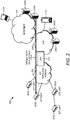
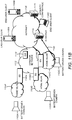
- FIG. 1 illustrates an example of a M2M and/or IoT network 200.
- the system or network 200 may include distributed units such as IoT units 202A-D.
- M2M and/or IoT units may be referred to as IoT units or devices.
- IoT units or devices may include M2M units or devices, IoT units or device, and/or other similar devices or units.
- IoT units or devices may include components such as those described with respect to the devices or WTRUs 102a-d in FIGs. 12A-12E .
- the IoT units 202A-D may be wireless devices, e.g., a set of wireless battery driven devices.
- the IoT units 202A-D may be communicated and/or controlled (e.g., directly) by a device or a back-end server such as devices 208A-D.
- devices 208A-D may include any suitable computer, device, server, database, node, server host, and/or the like.
- the IoT units 202A-D may be communicated and/or controlled ( e.g.
- DMS device management server
- end-user management clients or devices such as smart phones, computers such as laptop computers or desktops, tablets, and/or the like.
- end-user management clients or devices 212A and/or 212B may control or communicate with the IoT units 202A-D.
- the devices 208A-D and/or the end-user management clients or devices 212A and/or 212B may belong to an owner organization.
- the owner organization may be a gateway (GW) unit 210.
- the end-user management clients or devices 212A and/or 212B may control the end-user devices or units ( e.g ., 202A-D) directly or through one or more of the devices 208A-D.
- the end-user management clients or devices 212A and/or 212B control the end-user devices or units 202A-D, e.g ., through a DMS.
- the management clients or devices 212A and/or 212B may or may not have ( e.g ., may not need to have) security associations with each of the IoT units 202A-D.
- Security associations with some or all of the IoT units 202A-D may be provided and/or handled by one or more of the devices 208A-D on behalf of the management clients or devices 212A and/or 212B.
- the IoT units 202A-D may be connected to the GW 210, for example, to provide communication between the devices in the network 200 and/or to enable control by the devices 208A-D and/or the management clients or devices 212A and/or 212B of the IoT units 202A-D.
- the GW 210 may include a server, computer, database, device, and/or the like.
- the GW 210 may provide local network connectivity and/or global internet connectivity to the IoT units 202A-D.
- the IoT units 202A-D may have general Internet connectivity ( e.g ., to the Internet 205).
- An access thereto may be provided by the GW 210 and may be of different types including, but not limited to, cellular access, WLAN access, fixed broadband access or corporate network access, and/or the like.
- the IoT units 202A-D may be connected to an IoT wireless domain 204.
- the IoT wireless domain 204 may be connected to the GW 210.
- the GW 210 may be connected to LAN 206. Via or through the LAN 206, the GW 210 may be connected to the Internet 205 and may have internet connectivity.
- the GW 210 may provide Internet connectivity to the IoT devices 202A-D and/or provide communication to the back-end system such as devices 208A-D, and/or management clients or devices 212A and/or 212B using the LAN 206.
- One or more of the IoT units 202A-D may be connected to a cellular network.
- the cellular network may be one or more of the networks described in FIGs. 12A and 12C-E .
- One or more of the IoT units 202A-D may connect to the internet 205 through the cellular network.
- One or more of the IoT units 202A-D may be directly connected to the Internet 205.
- the management client devices 212A and/or 212B and/or the devices 208A-D may be connected to the Internet 205 to control, access, and/or manage the IoT units 202A-D.
- the devices 208A-B and/or the management client or device 212A may be connected to the Internet 205 ( e.g ., directly) to control, access, and/or manage the IoT units 202A-D.
- the DMSs 208C-D and/or the management client or device 212B may be connected to the LAN 206.
- the LAN 206 may provide connectivity to the Internet 205 such that the devices 208C-D and/or the management client or device 212B may control, access and/or manage the IoT units 202A-D.
- an end-to-end security channel 214A may be established between the management client 212A and an IoT unit such as the IoT unit 202A.
- An end-to-end security channel 214A may be established between one or more of the devices 208A-D and/or the management client 212B to provide connectivity thereto and/or communication there between.
- End-to-end security channels may enable trusted communication and relations between the IoT units 202A-D and the back end system ( e.g ., the devices 208A-D and/or the management clients or devices 212A and/or 212B), e.g ., by enabling them to securely identify each other.
- the end-to-end security channels (e.g ., 214A) may include and/or may be based on Internet Protocol Security (IPsec), Transport Layer Security (TLS), Datagram Transport Layer Security (DTLS), and/or the like.
- IPsec Internet Protocol Security
- TLS Transport Layer Security
- DTLS Datagram Transport Layer Security
- the end-to-end security channels may provide and/or use IoT unit credentials ( e.g ., unique for each of the IoT unit 202A-D).
- the IoT unit credentials may be installed on the IoT units or devices 202A-D.
- the IoT unit credentials may be included or be present on the DMSs 208A
- a Denial of Service (DoS) attack may occur on one or more of the IoT units ( e.g., 202A-D), for example, by one or more of the devices 208A-D and/or one or more of the management clients or devices 212A and/or 212B.
- an attacker such as a hostile organization or individual may try to destroy a system by launching a DoS attack ( e.g ., via an attacker such as one or more of the devices 208A-D and/or management clients or devices 212A and/or 212B) on one or more of the IoT units ( e.g., 202A-D) in the wireless domain ( e.g., 204).
- IoT units or devices may be vulnerable to DoS attacks as they may be or may include resource constrained units and/or may be powered by battery resources. They may be, for example, sensitive to DoS (e.g., a battery exhaustion attack).
- a DoS attack may be performed by launching hostile IP traffic from a single host (e.g., an attacker) as shown in FIG. 2 or by using a Distributed DoS (DDoS) as shown in FIG. 3 .
- a single host e.g., an attacker
- DDoS Distributed DoS
- an attacker such as a hostile organization or an individual may operate a server or device 208B and try to destroy ( e.g ., via a battery exhaustion attack) the IoT unit 202B by launching a single host DoS attack 220A on the IoT unit 202B.
- an attacker may use a server or device (e.g ., 208A-D and/or 212A, 212B as an attacker) to issue a number, e.g ., a large number of dummy requests.
- the dummy requests may include requests that are made up and/or issued with a purpose of overloading the victim device.
- the large number of dummy requests towards the IoT units may consume battery power of the IoT units.
- the IoT units may consume their battery power, e.g ., to the point where the battery power is exhausted or nearly exhausted.
- the dummy requests may or may not be real or valid requests.
- the dummy requests may be issued for the sole purpose of overloading the victim device.
- An attacker may use a server or device (e.g ., 208A-D and/or 212A, 212B as an attacker) to issue a large number of dummy requests towards the IoT unit(s) such that the IoT units may be incapable of handling legitimate requests.
- a server or device e.g ., 208A-D and/or 212A, 212B as an attacker
- one or more infected hosts or devices such as the DMSs or devices 208A, 208D may generate a DoS attack 220B, 220C respectively against the IoT unit 202B.
- the attacker may infect remote machines (e.g ., 208A, 208D) by installing attacking source code thereon.
- the source code when executed, the source code may generate DoS traffic or attacks from the remote machines (e.g ., 202A, 202D) against a chosen DoS target (e.g ., IoT unit 202B).
- the remote machines e.g ., 202A, 202D
- a chosen DoS target e.g ., IoT unit 202B
- routers may use filtering and other countermeasures to mitigate the effect of unsophisticated attacks.
- the filtering and other countermeasures may include one or more of the following: a verify reverse routing path, simple IP address filtering, edge router filtering, committed access rate (CAR), synchronize (SYN) packet rate limiting, and/or the like.
- a verify reverse routing path the router in the network may be configured to check whether an incoming source IP address has a route in an active routing table (e.g., a current, active routing table).
- an active routing table e.g., a current, active routing table.
- a router may use a lookup table with IP addresses or IP address ranges to determine where to send an incoming packet.
- a request may be sent to the router requesting that the router drop the packet.
- the router may be configured to allow incoming and/or outcoming IP addresses within specific ranges.
- routers at the edge of a private network e.g ., an edge router
- the filtering rule sets may be strict such that they may prevent packets ( e.g ., any packet) with source address outside the address range of the private network from leaving the network.
- the filtering rule sets may block incoming traffic (e.g ., any incoming packet) with source address belonging to the internal network.
- Committed Access Rate may use Internet control message protocol (ICMP) packets (e.g ., ping, and/or the like) to flood networks.
- ICMP Internet control message protocol
- a router CAR e.g ., the Cisco CAR
- SYN packet rate limiting a router may be configured to limit the amount of SYN packets and allow a certain amount of SYN packet to flow through.
- the router may limit the effect of SYN flooding attacks.
- IoT units or devices using cryptographic protocols may be sensitive to DoS attacks.
- the DoS attacks may try to drain the battery of the devices.
- a set-up phase of a cryptographic operation may incur significant power consumption cost.
- DTLS Datagram Transport Layer Security
- IKE IPSec Key Exchange
- the cookie may be a random value (e.g . unique, random value) that is generated by the DTLS and/or the IKE.
- the DTLS and/or the IKE may force an initiator in a handshake phase to echo a cookie value received in a response.
- a node that receives the response e.g.
- the device, server, node, and/or the like that may initiate a communication with the IoT unit may not start the costly handshake operations if a correct cookie value is not received.
- the cookie technique may protect the IoT units or devices using cryptographic protocols from some DDoS attacks.
- the cookie technique may or may not prevent advanced attacks where the attacker may receive the cookie and may respond to it, for example.
- Different approaches may be used to improve DoS robustness for IoT units (e.g., puzzle solving and/or the key based Message Authentication Code (MAC) examples described herein).
- One or more of the approaches may be based on forcing the attacker to solve a computational demanding puzzle to be able to proceed in the handshake operation.
- One or more of the approaches may be based on enforcing the initiator to include a short symmetric key based MAC value in a handshake/connection request (e.g ., the first handshake/connection request), enabling the IoT units/devices to directly check if a handshake request may be valid or not.
- the IoT units/devices may directly check if a handshake request is valid or not by calculating and checking a MAC in the header of a user datagram protocol (UDP) message (e.g ., the first UDP message sent in the DTLS handshake) and/or in a constrained application protocol (CoAP) connection request message (e.g ., the first CoAP connection request message).
- UDP user datagram protocol
- CoAP constrained application protocol
- the IoT units/devices and legitimate initiators may be given a pre-configured trusted relationship such that the legitimate initiators may have access to MAC integrity keys used by the IoT units/devices.
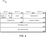
- the short MAC protected CoAP message format may be shown in FIG. 4 , which illustrates an example message format that may be used in one or more examples herein.
- FIG. 4 depicts the structure of a CoAP message.
- a CoAP message such as CoAP message 400 may include one or more of the following: a protocol version, (Ver) 410, a type field (T) 412, a Token field (TKL) 414, a Code field (Code) 416, A Message ID field (Message ID) 418, Request ID field 420, Validity Check field 422, Options field 424, and Payload filed 426.
- a byte may contain a protocol version (Ver) 410, a type field (T) 412 with basic message type information, and the size in bytes of a Token field (TKL) 414.
- a Code field (Code) 416 may contain additional, precise message type information.
- a Message ID field (Message ID) 418 may include an ID (e.g., a unique ID) used to track messages and detect possible duplications.
- the Token field 414 may be used to match requests and response messages, and the values of the Token field 414 may be generated for a request ( e.g ., a random request and/or uniquely for each request).
- a field may range between 0 and 8 bytes in size (e.g., Octet 1-4, 402-408). The size of the field may aim at making CoAP robust against IP-spoofing attacks. The field may be used in case security is not provided at the transport layer.
- Several different CoAP options may be defined (e.g ., at 424). A list of different CoAP options may be specified according to a Type-Length-Content scheme.
- the CoAP message content may be included in the Payload field 426.
- Validity check information may be included at 422.
- Techniques or approaches for the detection and prevention of DoS and/or DDoS attacks may ( e.g ., only) make it more difficult to perform massive scale DoS and/or DDoS attacks.
- Techniques or approaches may or may not be able to prevent advance battery drain attacks that may come from an infected node inside an internal network or attacks targeting an IoT unit/device ( e.g ., a particular IoT unit).
- the IoT unit/device may be reachable from outside the internal network.
- Some techniques or approaches may increase the efforts used by an attacker to drain an IoT unit/device. The attacker with enough resources may still be able to initiate an attack and cause damage on the IoT devices and/or units.
- Some techniques or approaches may put restrictions on which devices may be able to communicate with an IoT unit/device (e.g. , a particular IoT) and enable or allow the IoT unit/device to efficiently detect a DoS attack.
- An IoT unit/device under attack may use detection techniques or approaches to shut down a radio unit to avoid power costly operations while under attack. Shutting down the IoT device/unit may prevent legitimate clients from connecting to the IoT device/unit.
- systems, methods, and/or instrumentalities described herein may be provided that may combine efficient attack detection with an efficient reactive defense strategy.
- Systems, methods, and/or instrumentalities described herein may enable or allow the IoT device/unit to set-up connection(s) with legitimate external entities and/or may help prevent harmful DoS traffic from reaching the IoT device/unit.
- the systems, methods and/or instrumentalities may provide an IoT DoS protection where a resource constrained, wireless, IoT unit/device may cooperate with a dedicated GW ( e.g., 210) at a border of the IoT wireless domain ( e.g., 204) such that the IoT unit/device (e.g., 202A-D) may be protected from an attack, e.g ., an attack to drain its battery, and may be able to receive legitimate traffic.
- a dedicated GW e.g., 210) at a border of the IoT wireless domain (e.g., 204)
- the IoT unit/device e.g., 202A-D
- an attack e.g ., an attack to drain its battery
- FIGs. 5A-5C illustrate examples of systems, methods, and/or instrumentalities for providing IoT DoS protection using a gateway that may be used in one or more examples herein.
- the gateway may help prevent a battery drain attack and enable reception of legitimate traffic.
- an IoT unit e.g ., 202A-D
- may detect an attack e.g ., distinguish between valid and non-valid traffic.
- a non-valid traffic may include a packet that does not meet a filtering rule set (e.g., a current filtering rule set).
- an IoT unit may use a cryptographic integrity check, such as short MAC detection, to distinguish between valid and non-valid traffic (e.g ., potential hostile DoS traffic such as 220A).
- a cryptographic integrity check such as short MAC detection
- it may perform and/or apply and/or initiate one or more features shown in FIG. 5B-5C .
- an IoT unit 202B may connect to the GW 210 and may inform the GW 210 that it is under attack from a server or device, e.g ., 208B.
- the IoT unit 202B may request that the GW 210 to start a security filtering and/or implement filtering rule set(s), e.g., to protect the IoT unit 202B from the hostile traffic ( e.g., 220A).
- These filtering rule sets or approaches may include a range of forbidden IP addresses.
- the range of forbidden IP addresses may include traffic with addresses that may not be forwarded to the IoT unit 202B.
- the range may be associated with blocking of traffic except some higher layer protocols such as CoAP, blocking of messages except some with predefined identities and or identity ranges, blocking of protocols except DTLS connections, and/or the like.
- the IoT unit 202B may send to the GW 210 a sleeping time period (e.g., a period when the IoT unit 202B may not have the radio on for communication).
- the GW 210 may have or possess the information received at la to initiate or calculate a different packet filtering rule set, e.g., to protect the IoT unit 202B from hostile traffic.
- the GW 210 may measure the number of valid packets targeting the IoT unit 202B and may store some or all valid packets for the IoT unit 202B, e.g., in an internal packet queue. For example, some or all valid packets may be dropped if the number of valid packets exceeds a predetermined number.
- the IoT unit 202B may go into a sleep mode. The IoT unit 202B may come into an active mode after an agreed sleep time period and receive traffic that is not blocked by the GW 210.
- the GW 210 may measure a number of valid packets received from a server or device 208C.
- a valid packet may be a packet that passes according filtering rule sets (e.g., a current filtering rule set).
- the GW 210 may continue to receive packets during the sleep time period of the IoT unit 202B, and the packets received may be valid packets.
- the GW 210 may store the valid packets in a packet queue such as an internal packet queue.
- the GW 210 may forward the valid packets in the packet queue to the IoT unit 202B, e.g ., on a condition that the sleep time period may have passed and/or if the number of valid packets in the packet queue does not exceed a threshold (e.g ., a pre-defined threshold, for example as described herein). If the number of valid packets may be above a threshold, the GW 210 may update its filtering rule set to a restrictive setting without forwarding the valid packets to the IoT unit 202B. According to examples herein, the GW 210 may continue to measure the number of received valid packets and/or continue to update its filtering rule set.
- a threshold e.g ., a pre-defined threshold, for example as described herein.
- the number of valid packets under an updated filtering rule set may result in still too many valid packets received, for example, the number of valid packets may be over a threshold (e.g ., a pre-defined threshold as described herein).
- the GW 210 may send a general warning to the system responsible that it may be under severe attack against which it has no efficient protection.
- the system responsible may include an IoT device organization, an IoT device management system, and/or IoT network.
- FIG. 6 illustrates an example messaging diagram associated with defending against DoS attacks as described in examples herein.
- a GW 604 may receive a communication 606 directed to an IoT unit/device 602 (e.g ., from a legitimate client 624 or attacker 626).
- the GW 604 may forward the communication 608 to the IoT device 602.
- the GW 604 may forward a communication 610 that may be received from an attacker 626 to the IoT device 602 at 612.
- the GW 604 may receive ( e.g ., from the IoT unit/ device 602) at least one of the following: an indication that the communication from the attacker 626 may be part of an attack and/or an indication of a requested change to the filtering.
- the GW 604 may update filtering rule sets at 616 to prevent further communications from the attacker 626 to the IoT device 602 and may forward subsequent communications 620 that may pass and/or comply the updated filter rules at 622.
- the GW may receive from the IoT unit/device an indication of a sleep time and/or may send or transmit the subsequent communications to the IoT unit/device that may pass the updated filter rules after the indicated sleep time may have elapsed.
- the subsequent communications may pass the updated filter rule based on a threshold associated with valid and non-valid packets of the subsequent communications according to examples discussed herein.
- a communication may be associated with an attack based on a determination using short MAC DoS protection (e.g ., 606-12, 618-622).
- Updating the filtering rule sets may include one or more of the following: updating a range of forbidden IP address(es), blocking traffic to the IoT device ( e.g. , except traffic with higher layer protocols such as CoAP), blocking messages ( e.g., except some with predefined identities and or identity ranges), blocking protocols ( e.g., except DTLS connections), and/or the like.
- the IoT unit/device 602 may receive 612, from the GW 604, and the communication 610 from the attacker 626.
- the IoT unit/device 602 may determine ( e.g ., using short MAC DoS protection) that the communication 612 may be part of an attack.
- the IoT unit/device 602 may send to the GW 604 an indication 614 that the communication from the attacker 626 may be an attack.
- the filtering rule sets 616 may be updated ( e.g ., by the GW 604) to prevent further communications such as 618 from the attacker 626 to the IoT unit/device 602, e.g., in response to the indication from the IoT unit 602 that the communication 610 from the attacker 626 may be an attack).
- the IoT unit/device 602 may send, to the GW 604, an indication of the sleep time (e.g., a time period during which the IoT unit/device 602 will not process communications from the GW 604.
- communication 620 from a legitimate client 624 may be received and may be forwarded onto the IoT device 602 at 622 ( e.g., if the communication 620 passes the filtering rule sets) while the communication 618 from the attacker 626 may be prevented or may not be forwarded as described herein.
- the examples described herein may be a complement to the protection of DoS and DDoS attacks based on active or static filtering or DoS detection techniques and/or approaches ( e.g ., described herein above) in combination with filtering.
- a higher level of protection of individual and/or sensitive IoT units may be provided.
- the examples herein may use the efficient DoS detection systems, methods, and/or instrumentalities described herein e.g ., with a collaboration protocol between a IoT unit/device and a GW, which may be at the border of the IoT wireless domain.
- the GW may be more powerful and/or efficient than the IoT unit/device.
- the GW may efficiently protect the IoT unit/device (e.g ., wireless IoT unit/device) from battery drain attacks and may allow legitimate traffic to reach the IoT unit/device.
- One or more features described herein may reduce the communication capabilities of the IoT unit/device. Such feature(s) may not stop it ( e.g ., completely stop it) from performing its potential critical communication task even when it is under a battery drain DoS attack.
- the systems, methods, and/or instrumentalities herein may be described and/or used with a system set-up according to short MAC DoS protection and may provide that the IoT units (e.g ., 202A-D) may communicate with external peers using Internet Engineering Task Force (IETF) defined protocol such as CoAP.
- IETF Internet Engineering Task Force
- the IoT devices/units may share a long lived master key ( K M ) with a Key Distribution Centre (KDC) ( e.g., 216).
- the clients that may want to communicate with the IoT unit/device may ( e.g., first) contact the KDC to get or receive a session key ( Ks ) and/or other information that may be used to send valid CoAP requests to the IoT unit/device.
- the IoT unit/device and client may start communicating with the desired IoT unit/device to generate a valid CoAP message header(s), e.g., after or upon receiving KS and a CoAP message ID (IDS).
- the valid CoAP message header(s) may be accepted by the IoT unit/device without being rejected as DoS attempts, as shown in FIG. 7 .
- FIG. 7 illustrates an example of a system and/or method for providing a prerequisite for providing IoT DoS protection that may be used in one or more examples herein.
- an IoT unit/device e.g., 202A
- the KDC e.g., 216
- the client e.g., 212B
- the KDC e.g., 216
- the key e.g., a K M
- other information e.g., a K M
- the IoT unit (e.g., 202A) and the client (e.g., 212A) may start communicating with each other ( e.g., via the GW 210 in an example) using a secure channel that may be set up based on the key ( K M , K S , ID S , and/or the like).
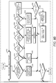
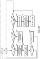
- FIG. 8A-8C illustrates an example diagram of one or more features, e.g ., at a gateway, for defending against DoS attacks as described in examples herein.
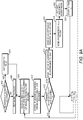
- FIG. 9 illustrates an example diagram of one or more features, e.g ., at an IoT device or unit, for defending against DoS attacks as described in examples herein.
- the method may be used, for example, when an IoT unit may be under battery drain DoS attack, and an attacker may send a large number of CoAP request messages to the IoT unit under attack.
- Such principles or approaches may be used with another application protocol (e.g ., in addition to the examples described herein with respect to CoAP).
- a GW may initialize parameters at 800.
- the GW may initialize the values for various threshold parameters including s , m, and/or t .
- the GW may initialize s to zero or relatively zero.
- the GW may initialize m and or t to a value of a suitable system constant that is set by an administrator.
- the GW may determine whether to share session key with a IoT unit at 802.
- the GW may receive packet filtering rule sets from IoT units/devices (e.g ., the DoS information described herein) at 808.
- the GW may start or update a DoS filter for the protection of the IoT unit according to the packet filtering rule sets.
- the GW may measure a lapse of time since the reception of the packets to be able to determine, for example, when the IoT units may wake up again.
- the DoS filter may be applied according to a process. For example, in FIG.
- the GW may receive packets that may have the destination address of the IoT unit and may check the packets (e.g ., the GW may check the packets with respect to their higher level protocol) at 812.
- the GW may determine whether the IoT unit is under attack at 814. For example, the GW may determine that the IoT unit is under attack based on a message from the IoT unit. If the GW determines that the GW is under an attack at 814, the GW may determine whether the packet is a CoAP packet at 816. If the packet is determined to be a CoAP packet, the GW may determine whether the CoAP packet may be within a valid internet protocol IP range at 818.
- the packet may be dropped at 840, and the GW may update a filtering set at 840 and decide whether c2 is greater than s at 848. If the packet is determined to be a CoAP packet at 816, the GW may determine whether the CoAP packet is within a valid internet protocol (IP) range. If the CoAP packet is not within a valid internet protocol IP range (e.g. , the packet may include a forbidden IP source) at 818, the GW drop the packet, and update the filtering set at 840. If the CoAP packet is determined to be within a valid internet protocol IP range at 818, the GW may determine whether the packet include a valid message ID at 820.
- IP internet protocol
- a e.g., the number of accepted packets per second
- the packet may be accepted as a packet from an valid ongoing CoAP session and it may be stored in a waiting queue buffer.
- the set ID p may be updated according to a suitable acceptance window algorithm or method.
- a window algorithm or method may include, for example, a sliding window method that may be applied where the last received packet ID may be removed from the set ID p and a different ID may be added to the ID p set.
- the different ID may, for example, be the current "end mark" ID of the sliding window plus a given constant value modulus the maximum ID value in the set ID p .
- the GW may forward the packet to the IoT unit at 828. For example, if ID ⁇ ID q , the packet may be accepted as a packet from a new CoAP session and it may be stored in a waiting queue buffer and the set ID q may be updated according to the suitable acceptance window algorithm. If the packet is determined not to include a valid mac at 826, the GW may drop the packet and update the parameter, r , which may determine the number of received false packets per second towards the IoT unit at 846, and the GW may decide whether c2 is greater than s at 848.
- the GW may decide whether c 2 is greater than s at 848.
- the GW may forward the IP packet to a destination at 838.
- the GW may determine whether c 2 is greater than s at 848. If c2 is determined to be greater than s at 848, the GW may receive packets that may have the destination address of the IoT unit and may check the packets ( e.g ., the GW may check the packets with respect to their higher level protocol) at 812 and go through the process as described herein. If c2 is determined not to be greater than s at 848, the GW may determine whether a is less than m at 850. The GW may measure the number of accepted packets per second, a, that may be targeting the IoT device. m may be a maximum number of allowed IP packets per second.
- the GW may receive packets that may have the destination address of the IoT unit and may check the packets (e.g ., the GW may check the packets with respect to their higher level protocol) at 812 and go through the process as described herein.
- the GW may update ID filter at 866.
- the GW may request and receive session key data from the IoT unit at 868.
- the GW may receive packets that may have the destination address of the IoT unit and may check the packets ( e.g ., the GW may check the packets with respect to their higher level protocol) at 812 and go through the process as described herein.
- the GW may measure the number of accepted packets per second, a, that may be targeting the IoT device. If a is determined to be less than m at 850, the GW may forward some or all packets in queue to the IoT unit at 856.
- the GW may initialize a and restart timer c2 at 858.
- the GW may measure the number of dropped packets per second targeting the IoT device, which may be denoted by r packets/second. The GW may compare the number of dropped packets per second targeting the IoT device against a threshold value t . The GW may determine whether r is less than t at 860. If r is determined to be less than t at 860, the GW may disable timer at 862. The GW may determine whether to share session key with the IoT unit at 802 and go through the process as described herein. If r is determined not to be less than t at 860, the GW may receive packets that may have the destination address of the IoT unit and may check the packets ( e.g. , the GW may check the packets with respect to their higher level protocol) at 812 and go through the process as described herein.
- the GW may use the parameters received to check the messages it receives for the IoT unit.
- the GW may be able to validate and/or check an integrity check value, for messages coming from valid CoAP sessions with the IoT unit, and valid messages may be forwarded to the IoT unit while other packets may be blocked.
- the GW may determine or check whether r may below the threshold value t. In an example (e.g., if the value may below the threshold), the packet filter towards the IoT unit may be disabled and the method may proceed as described herein. If the value may be above the threshold, the method may proceed as described herein.
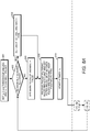
- FIG. 9 illustrates an example diagram of one or more features, e.g ., at an IoT device or unit, for defending against DoS attacks as described in examples herein.
- the IoT unit may determine whether sharing session key is allowed at 902. If sharing the session key is allowed at 902, the IoT may set mark to true. If sharing the session key is not allowed at 902, the IoT may set mark to false at 906.
- the IoT device may receive and check IP packets and record a number of invalid packets per second at 908.
- the IoT unit may store IP address ranges from likely, e.g ., highly likely, DoS sources at 910.
- the IoT unit may receive CoAP request messages from different servers (e.g ., 202A-D) on the Internet and may determine or check the validity using the received message ID in the CoAP message header of the messages. If the received message ID is determined to be valid, it may be used together with K M to calculate a potential session key, Ks, according to examples such as a DTLS pre-shared secret or a symmetric key. For example, the received message ID may be used to calculate short MAC checks in the CoAP header. For example, the session key K S may be used to check the validity of the current and subsequent sequence of messages within a same CoAP session.
- the IoT unit may be under DoS attack. For example, a large number of CoAP request messages may not be valid.
- the IoT unit may store IP address ranges from likely DoS sources at 910. For example, for a ( e.g., each) non-valid CoAP request, the IoT unit may record and/or store the source IP address of the non-valid packet. The IoT unit may determine whether the number of false packets per second is greater than a threshold at 912. If the number of received false-packets per second may exceed a predefined threshold, e.g., t packets/second, the IoT unit may contact the GW and send a request to start a DoS filtering protection.
- a threshold e.g., t packets/second
- the IoT unit may send a list of IP address ranges to GW such that the GW may block the packets with the IP addresses in the list at 914. If the number of false packets per second is not greater than a threshold, the IoT unit may receive and check IP packets and record the number of invalid packets per second at 908 and go through the process described herein.
- the IoT unit may send ID acceptance window data to the GW at 916.
- the IoT unit may send one or more parameters to the GW ( e.g., m, s, t ).
- the one or more parameters may be included in a request to change a filtering rule set.
- the request that the IoT unit sends to the GW may include one or more of the following information: a list of recorded source IP addresses or a range of IP addresses that the IoT units may want to be blocked; a maximum number of allowed IP packets per second, m; a set of parameters, P , that may define a set of message ID values and/or message sequence numbers that may be accepted by the IoT unit as valid CoAP message IDs.
- the set of message ID values may include a set defined by an acceptance window parameter.
- the IoT unit may go into a sleep mode at 920.
- the IoT unit may start a timer c1 at 922.
- the IoT may use an internal clock to determine whether the clock exceeds a sleep time period at 924. For example, the IoT unit may determine whether c1 is greater than s at 924.
- the IoT unit may continue to determine whether c1 is greater than s at 924 if the IoT unit enters a sleep mode at 920 and start the time c1 at 922.
- the IoT unit may continue to determine whether c1 is greater than s at 924 if c1 is not greater than s .
- the GW may receive the DoS information described herein from the IoT unit and may start a DoS filter for the protection of the IoT unit.
- the IoT unit may activate radio, if the radio is not already activated at 926. For example, when c1 > s , the IoT unit may activate its radio and may be capable of receiving traffic from the GW.
- DTLS protection may be provided and/or used.
- the IoT unit may or may not detect a false IP request using a CoAP header MAC, but may use a MAC in the DTLS header.
- a session key may or may not be shared between the IoT unit and the GW. Sharing a session key may break the end-to-end DTLS security.
- DTLS sequence numbers may be used instead of message ID values for filtering.
- DTLS sequence numbers may provide one or more changes to the DTLS record layer sequence number handling. For example, the changes may include a modification such that not every DTLS layer sequence number may be accepted as a valid sequence number.
- the sequence number may belong to a predefined acceptance set (e.g., ID p and/or ID q ).
- a filtering unit in a provider network such as the cloud may be provided and/or used.
- a filtering function may or may not be performed in a GW at the border of the IoT wireless domain.
- a DoS filtering method or technique in the provider network e.g ., the cloud
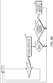
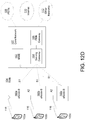
- FIG. 10 illustrates an example of a system and/or method for providing filtering and/or IoT DoS protection via a cloud. The method or technique shown in FIG. 10 may be used in one or more examples herein.
- a cloud 207 may include the functionality of the GW (e.g., 210) described herein for filtering and/or handling an attack while enabling valid communications.
- One or more examples herein may be used and/or provided in various use cases.
- a user may purchase a surveillance security service from a security company.
- a system including the surveillance security service and the security company may be provided and/or used to implement one or more of the examples herein.
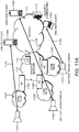
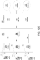
- FIGs. 11A-11B illustrate an example of a system (e.g., the real-world scenario described herein) in which one or more examples described herein may be used and/or implemented.
- an end-user client 1108B may communicate with a camera 1102B.
- the camera 1102B may include a pre-configured security relation with the security company 1116 such as KDC.
- the end-user client 1108B may connect to the camera 1102B using an end-to-end security connection 1114B by contacting the security company 1116 asking for the session-key material to secure the communication as described herein.
- the end-user client 1108B may trust the security company 1116 to handle end-to-end security keys on behalf of the end-user client 1108B.
- the end-user client 1108B may trust the security company 1116 that the security company 1116 may not use the keys for an unsolicited purposes.
- the surveillance cameras 1102A-C that are used by the end-user client 1108A-C may be battery driven and/or connected to the user's home WLAN 1104A-C.
- FIG. 11B illustrates a DoS attack.
- the attacker 1118 may determine to send a request 1120 to the surveillance camera 1102C on the home network 1104C.
- the attacker 1118 may pretend to set up secure video sessions with the surveillance camera 1102C.
- the attack may or may not give the attacker access to the surveillance camera 1102C or secure video stream 1114C sent from the camera.
- the attack may drain the battery of the surveillance camera 1102C and make it inoperable.
- the attack may lead to traffic blocking.
- the surveillance camera 1102C or the end-user client 1108C may include a strict DoS filter.
- the DoS filter may block traffic towards the surveillance camera under attack 1102C, including traffic from legitimate clients.
- the attack may make the camera inoperable.
- the surveillance camera under attack 1102C may become inoperable if the attacker keeps sending a request to the surveillance camera 1102C pretending to set up secure video sessions with the surveillance camera 1102C.
- An operator network 1112 may include a DoS filtering service (e.g. , the GW 1110 in its network). Potential sensitive information such as secret session keys and a master key may or may not be given to the operator network 1112.
- the DoS filtering service may protect the surveillance cameras 1102A-C from the DoS attack described herein.
- the surveillance camera under attack 1102C may detect a large number of false session set-up requests from the Internet 1105.
- the surveillance camera under attack 1102C may contact the GW 1110 in the operator network 1112.
- the surveillance camera 1102C may ask the GW 1110 in the operator network 1112 to deploy a DoS filter for traffic directed towards the surveillance camera 1102C in the home network 1104C.
- the surveillance camera 1102C may ask the GW 1110 in the operator network 1112 to deploy a DoS filter for traffic targeting the home network 1104C.
- the surveillance camera 1102C may give the GW 1110 parameters that allow the GW 1110 to distinguish valid message ID from non-valid message ID according to the security policy of the surveillance camera 1102C and processes/approaches described herein.
- the GW 1110 may be able to apply a DoS filter without knowing secret session keys that may be used by the surveillance camera 1102C and the end-user client 1108C.
- the GW 1110 may be able to apply a DoS filter without knowing a master key shared between the security company 1116 and the surveillance camera 1102C.
- the GW 1110 may start deploying the DoS filter and may allow IP packets with valid message ID /sequence numbers to be passed to the surveillance camera 1102C.
- the attacker 1118 may or may not be able to find valid message ID ranges, for example, without intercepting traffic 1114C from the non-attacker end-user client 1108C towards the surveillance camera 1102C.
- a majority of DoS attack packets 1120 may be blocked without reaching the surveillance camera 1102C.
- the non-attacker end-user client 1108C may be able to calculate valid message IDs and may be allowed to communicate with surveillance camera 1102C securely while the DoS attack may be ongoing.
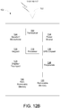
- FIG. 12A depicts a diagram of an example communications system 100 in which one or more disclosed embodiments may be implemented.
- the communications system 100 may be a multiple access system that provides content, such as voice, data, video, messaging, broadcast, etc., to multiple wireless users.
- the communications system 100 may enable multiple wireless users to access such content through the sharing of system resources, including wireless bandwidth.
- the communications systems 100 may employ one or more channel access approaches, such as code division multiple access (CDMA), time division multiple access (TDMA), frequency division multiple access (FDMA), orthogonal FDMA (OFDMA), single-carrier FDMA (SC-FDMA), and the like.
- CDMA code division multiple access
- TDMA time division multiple access
- FDMA frequency division multiple access
- OFDMA orthogonal FDMA
- SC-FDMA single-carrier FDMA
- the communications system 100 may include wireless transmit/receive units (WTRUs) 102a, 102b, 102c, and/or 102d (which generally or collectively may be referred to as WTRU 102), a radio access network (RAN) 103/104/105, a core network 106/107/109, a public switched telephone network (PSTN) 108, the Internet 110, and other networks 112, though it will be appreciated that the disclosed embodiments contemplate any number of WTRUs, base stations, networks, and/or network elements.
- Each of the WTRUs 102a, 102b, 102c, and/or 102d may be any type of device configured to operate and/or communicate in a wireless environment.
- the WTRUs 102a, 102b, 102c, and/or 102d may be configured to transmit and/or receive wireless signals and may include user equipment (UE), a mobile station, a fixed or mobile subscriber unit, a pager, a cellular telephone, a personal digital assistant (PDA), a smartphone, a laptop, a netbook, a personal computer, a wireless sensor, consumer electronics, and the like.
- UE user equipment
- PDA personal digital assistant
- smartphone a laptop
- netbook a personal computer
- a wireless sensor consumer electronics, and the like.
- the communications systems 100 may also include a base station 114a and a base station 114b.
- Each of the base stations 114a, 114b may be any type of device configured to wirelessly interface with at least one of the WTRUs 102a, 102b, 102c, and/or 102d to facilitate access to one or more communication networks, such as the core network 106/107/109, the Internet 110, and/or the networks 112.
- the base stations 114a and/or 114b may be a base transceiver station (BTS), a Node-B, an eNode B, a Home Node B, a Home eNode B, a site controller, an access point (AP), a wireless router, and the like. While the base stations 114a, 114b are each depicted as a single element, it will be appreciated that the base stations 114a, 114b may include any number of interconnected base stations and/or network elements.
- the base station 114a may be part of the RAN 103/104/105, which may also include other base stations and/or network elements (not shown), such as a base station controller (BSC), a radio network controller (RNC), relay nodes, etc.
- BSC base station controller
- RNC radio network controller
- the base station 114a and/or the base station 114b may be configured to transmit and/or receive wireless signals within a particular geographic region, which may be referred to as a cell (not shown).
- the cell may further be divided into cell sectors.
- the cell associated with the base station 114a may be divided into three sectors.
- the base station 114a may include three transceivers, i.e., one for each sector of the cell.
- the base station 114a may employ multiple-input multiple output (MIMO) technology and, therefore, may utilize multiple transceivers for each sector of the cell.
- MIMO multiple-input multiple output
- the base stations 114a and/or 114b may communicate with one or more of the WTRUs 102a, 102b, 102c, and/or 102d over an air interface 115/116/117, which may be any suitable wireless communication link (e.g ., radio frequency (RF), microwave, infrared (IR), ultraviolet (UV), visible light, etc.).
- the air interface 115/116/117 may be established using any suitable radio access technology (RAT).
- RAT radio access technology
- the communications system 100 may be a multiple access system and may employ one or more channel access schemes, such as CDMA, TDMA, FDMA, OFDMA, SC-FDMA, and the like.
- the base station 114a in the RAN 103/104/105 and the WTRUs 102a, 102b, and/or 102c may implement a radio technology such as Universal Mobile Telecommunications System (UMTS) Terrestrial Radio Access (UTRA), which may establish the air interface 115/116/117 using wideband CDMA (WCDMA).
- WCDMA may include communication protocols such as High-Speed Packet Access (HSPA) and/or Evolved HSPA (HSPA+).
- HSPA may include High-Speed Downlink Packet Access (HSDPA) and/or High-Speed Uplink Packet Access (HSUPA).
- the base station 114a and the WTRUs 102a, 102b, and/or 102c may implement a radio technology such as Evolved UMTS Terrestrial Radio Access (E-UTRA), which may establish the air interface 115/116/117 using Long Term Evolution (LTE) and/or LTE-Advanced (LTE-A).
- E-UTRA Evolved UMTS Terrestrial Radio Access
- LTE Long Term Evolution
- LTE-A LTE-Advanced
- the base station 114a and the WTRUs 102a, 102b, and/or 102c may implement radio technologies such as IEEE 802.16 (i.e., Worldwide Interoperability for Microwave Access (WiMAX)), CDMA2000, CDMA2000 IX, CDMA2000 EV-DO, Interim Standard 2000 (IS-2000), Interim Standard 95 (IS-95), Interim Standard 856 (IS-856), Global System for Mobile communications (GSM), Enhanced Data rates for GSM Evolution (EDGE), GSM EDGE (GERAN), and the like.
- IEEE 802.16 i.e., Worldwide Interoperability for Microwave Access (WiMAX)
- CDMA2000, CDMA2000 IX, CDMA2000 EV-DO Code Division Multiple Access 2000
- IS-95 Interim Standard 95
- IS-856 Interim Standard 856
- GSM Global System for Mobile communications
- GSM Global System for Mobile communications
- EDGE Enhanced Data rates for GSM Evolution
- GERAN GSM EDGERAN
- the base station 114b in FIG. 12A may be a wireless router, Home Node B, Home eNode B, or access point, for example, and may utilize any suitable RAT for facilitating wireless connectivity in a localized area, such as a place of business, a home, a vehicle, a campus, and the like.
- the base station 114b and the WTRUs 102c, 102d may implement a radio technology such as IEEE 802.11 to establish a wireless local area network (WLAN).
- the base station 114b and the WTRUs 102c, 102d may implement a radio technology such as IEEE 802.15 to establish a wireless personal area network (WPAN).
- WLAN wireless local area network
- WPAN wireless personal area network
- the base station 114b and the WTRUs 102c, 102d may utilize a cellular-based RAT (e.g ., WCDMA, CDMA2000, GSM, LTE, LTE-A, etc.) to establish a picocell or femtocell.
- a cellular-based RAT e.g ., WCDMA, CDMA2000, GSM, LTE, LTE-A, etc.
- the base station 114b may have a direct connection to the Internet 110.
- the base station 114b may not be required to access the Internet 110 via the core network 106/107/109.
- the RAN 103/104/105 may be in communication with the core network 106/107/109, which may be any type of network configured to provide voice, data, applications, and/or voice over internet protocol (VoIP) services to one or more of the WTRUs 102a, 102b, 102c, and/or 102d.
- the core network 106/107/109 may provide call control, billing services, mobile location-based services, pre-paid calling, Internet connectivity, video distribution, etc., and/or perform high-level security functions, such as user authentication.
- the RAN 103/104/105 and/or the core network 106/107/109 may be in direct or indirect communication with other RANs that employ the same RAT as the RAN 103/104/105 or a different RAT.
- the core network 106/107/109 may also be in communication with another RAN (not shown) employing a GSM radio technology.
- the core network 106/107/109 may also serve as a gateway for the WTRUs 102a, 102b, 102c, and/or 102d to access the PSTN 108, the Internet 110, and/or other networks 112.
- the PSTN 108 may include circuit-switched telephone networks that provide plain old telephone service (POTS).
- POTS plain old telephone service
- the Internet 110 may include a global system of interconnected computer networks and devices that use common communication protocols, such as the transmission control protocol (TCP), user datagram protocol (UDP) and the internet protocol (IP) in the TCP/IP internet protocol suite.
- the networks 112 may include wired or wireless communications networks owned and/or operated by other service providers.
- the networks 112 may include another core network connected to one or more RANs, which may employ the same RAT as the RAN 103/104/105 or a different RAT.
- the WTRUs 102a, 102b, 102c, and/or 102d in the communications system 100 may include multi-mode capabilities, i.e., the WTRUs 102a, 102b, 102c, and/or 102d may include multiple transceivers for communicating with different wireless networks over different wireless links.
- the WTRU 102c shown in FIG. 12A may be configured to communicate with the base station 114a, which may employ a cellular-based radio technology, and with the base station 114b, which may employ an IEEE 802 radio technology.
- FIG. 12B depicts a system diagram of an example WTRU 102.
- the WTRU 102 may include a processor 118, a transceiver 120, a transmit/receive element 122, a speaker/microphone 124, a keypad 126, a display/touchpad 128, non-removable memory 130, removable memory 132, a power source 134, a global positioning system (GPS) chipset 136, and other peripherals 138.
- GPS global positioning system
- the base stations 114a and 114b, and/or the nodes that base stations 114a and 114b may represent, such as but not limited to transceiver station (BTS), a Node-B, a site controller, an access point (AP), a home node-B, an evolved home node-B (eNodeB), a home evolved node-B (HeNB), a home evolved node-B gateway, and proxy nodes, among others, may include some or all of the elements depicted in FIG. 12B and described herein.
- BTS transceiver station
- Node-B a Node-B
- AP access point
- eNodeB evolved home node-B
- HeNB home evolved node-B gateway
- proxy nodes among others, may include some or all of the elements depicted in FIG. 12B and described herein.
- the processor 118 may be a general purpose processor, a special purpose processor, a conventional processor, a digital signal processor (DSP), a plurality of microprocessors, one or more microprocessors in association with a DSP core, a controller, a microcontroller, Application Specific Integrated Circuits (ASICs), Field Programmable Gate Array (FPGAs) circuits, any other type of integrated circuit (IC), a state machine, and the like.
- the processor 118 may perform signal coding, data processing, power control, input/output processing, and/or any other functionality that enables the WTRU 102 to operate in a wireless environment.
- the processor 118 may be coupled to the transceiver 120, which may be coupled to the transmit/receive element 122. While FIG. 12B depicts the processor 118 and the transceiver 120 as separate components, it may be appreciated that the processor 118 and the transceiver 120 may be integrated together in an electronic package or chip.
- the transmit/receive element 122 may be configured to transmit signals to, or receive signals from, a base station (e.g., the base station 114a) over the air interface 115/116/117.
- a base station e.g., the base station 114a
- the transmit/receive element 122 may be an antenna configured to transmit and/or receive RF signals.
- the transmit/receive element 122 may be an emitter/detector configured to transmit and/or receive IR, UV, or visible light signals, for example.
- the transmit/receive element 122 may be configured to transmit and receive both RF and light signals. It will be appreciated that the transmit/receive element 122 may be configured to transmit and/or receive any combination of wireless signals.
- the WTRU 102 may include any number of transmit/receive elements 122. More specifically, the WTRU 102 may employ MIMO technology. Thus, in one embodiment, the WTRU 102 may include two or more transmit/receive elements 122 ( e.g., multiple antennas) for transmitting and receiving wireless signals over the air interface 115/116/117.
- the WTRU 102 may include two or more transmit/receive elements 122 ( e.g., multiple antennas) for transmitting and receiving wireless signals over the air interface 115/116/117.
- the transceiver 120 may be configured to modulate the signals that are to be transmitted by the transmit/receive element 122 and to demodulate the signals that are received by the transmit/receive element 122.
- the WTRU 102 may have multi-mode capabilities.
- the transceiver 120 may include multiple transceivers for enabling the WTRU 102 to communicate via multiple RATs, such as UTRA and IEEE 802.11, for example.
- the processor 118 of the WTRU 102 may be coupled to, and may receive user input data from, the speaker/microphone 124, the keypad 126, and/or the display/touchpad 128 (e.g., a liquid crystal display (LCD) display unit or organic light-emitting diode (OLED) display unit).
- the processor 118 may also output user data to the speaker/microphone 124, the keypad 126, and/or the display/touchpad 128.
- the processor 118 may access information from, and store data in, any type of suitable memory, such as the non-removable memory 130 and/or the removable memory 132.
- the non-removable memory 130 may include random-access memory (RAM), read-only memory (ROM), a hard disk, or any other type of memory storage device.
- the removable memory 132 may include a subscriber identity module (SIM) card, a memory stick, a secure digital (SD) memory card, and the like.
- SIM subscriber identity module
- SD secure digital
- the processor 118 may access information from, and store data in, memory that is not physically located on the WTRU 102, such as on a server or a home computer (not shown).
- the processor 118 may receive power from the power source 134, and may be configured to distribute and/or control the power to the other components in the WTRU 102.
- the power source 134 may be any suitable device for powering the WTRU 102.
- the power source 134 may include one or more dry cell batteries (e.g ., nickel-cadmium (NiCd), nickel-zinc (NiZn), nickel metal hydride (NiMH), lithium-ion (Li-ion), etc.), solar cells, fuel cells, and the like.
- the processor 118 may also be coupled to the GPS chipset 136, which may be configured to provide location information (e.g ., longitude and latitude) regarding the current location of the WTRU 102.
- location information e.g ., longitude and latitude
- the WTRU 102 may receive location information over the air interface 115/116/117 from a base station (e.g ., base stations 114a, 114b) and/or determine its location based on the timing of the signals being received from two or more nearby base stations. It will be appreciated that the WTRU 102 may acquire location information by way of any suitable location-determination method while remaining consistent with an embodiment.
- the processor 118 may further be coupled to other peripherals 138, which may include one or more software and/or hardware modules that provide additional features, functionality and/or wired or wireless connectivity.
- the peripherals 138 may include an accelerometer, an e-compass, a satellite transceiver, a digital camera (for photographs or video), a universal serial bus (USB) port, a vibration device, a television transceiver, a hands free headset, a Bluetooth® module, a frequency modulated (FM) radio unit, a digital music player, a media player, a video game player module, an Internet browser, and the like.
- the peripherals 138 may include an accelerometer, an e-compass, a satellite transceiver, a digital camera (for photographs or video), a universal serial bus (USB) port, a vibration device, a television transceiver, a hands free headset, a Bluetooth® module, a frequency modulated (FM) radio unit, a digital music player, a media player, a video game player
- FIG. 12C depicts a system diagram of the RAN 103 and the core network 106 according to an embodiment.
- the RAN 103 may employ a UTRA radio technology to communicate with the WTRUs 102a, 102b, and/or 102c over the air interface 115.
- the RAN 103 may also be in communication with the core network 106.
- the RAN 103 may include Node-Bs 140a, 140b, and/or 140c, which may each include one or more transceivers for communicating with the WTRUs 102a, 102b, and/or 102c over the air interface 115.
- the Node-Bs 140a, 140b, and/or 140c may each be associated with a particular cell (not shown) within the RAN 103.
- the RAN 103 may also include RNCs 142a and/or 142b. It will be appreciated that the RAN 103 may include any number of Node-Bs and RNCs while remaining consistent with an embodiment.
- the Node-Bs 140a and/or 140b may be in communication with the RNC 142a. Additionally, the Node-B 140c may be in communication with the RNC142b.
- the Node-Bs 140a, 140b, and/or 140c may communicate with the respective RNCs 142a, 142b via an Iub interface.
- the RNCs 142a, 142b may be in communication with one another via an Iur interface.
- Each of the RNCs 142a, 142b may be configured to control the respective Node-Bs 140a, 140b, and/or 140c to which it is connected.
- each of the RNCs 142a, 142b may be configured to carry out or support other functionality, such as outer loop power control, load control, admission control, packet scheduling, handover control, macrodiversity, security functions, data encryption, and the like.
- the core network 106 shown in FIG. 12C may include a media gateway (MGW) 144, a mobile switching center (MSC) 146, a serving GPRS support node (SGSN) 148, and/or a gateway GPRS support node (GGSN) 150. While each of the foregoing elements are depicted as part of the core network 106, it will be appreciated that any one of these elements may be owned and/or operated by an entity other than the core network operator.
- MGW media gateway
- MSC mobile switching center
- SGSN serving GPRS support node
- GGSN gateway GPRS support node
- the RNC 142a in the RAN 103 may be connected to the MSC 146 in the core network 106 via an IuCS interface.
- the MSC 146 may be connected to the MGW 144.
- the MSC 146 and the MGW 144 may provide the WTRUs 102a, 102b, and/or 102c with access to circuit-switched networks, such as the PSTN 108, to facilitate communications between the WTRUs 102a, 102b, and/or 102c and traditional land-line communications devices.
- the RNC 142a in the RAN 103 may also be connected to the SGSN 148 in the core network 106 via an IuPS interface.
- the SGSN 148 may be connected to the GGSN 150.
- the SGSN 148 and the GGSN 150 may provide the WTRUs 102a, 102b, and/or 102c with access to packet-switched networks, such as the Internet 110, to facilitate communications between and the WTRUs 102a, 102b, and/or 102c and IP-enabled devices.
- the core network 106 may also be connected to the networks 112, which may include other wired or wireless networks that are owned and/or operated by other service providers.
- FIG. 12D depicts a system diagram of the RAN 104 and the core network 107 according to an embodiment.
- the RAN 104 may employ an E-UTRA radio technology to communicate with the WTRUs 102a, 102b, and/or 102c over the air interface 116.
- the RAN 104 may also be in communication with the core network 107.
- the RAN 104 may include eNode-Bs 160a, 160b, and/or 160c, though it will be appreciated that the RAN 104 may include any number of eNode-Bs while remaining consistent with an embodiment.
- the eNode-Bs 160a, 160b, and/or 160c may each include one or more transceivers for communicating with the WTRUs 102a, 102b, and/or 102c over the air interface 116.
- the eNode-Bs 160a, 160b, and/or 160c may implement MIMO technology.
- the eNode-B 160a for example, may use multiple antennas to transmit wireless signals to, and receive wireless signals from, the WTRU 102a.
- Each of the eNode-Bs 160a, 160b, and/or 160c may be associated with a particular cell (not shown) and may be configured to handle radio resource management decisions, handover decisions, scheduling of users in the uplink and/or downlink, and the like. As shown in FIG. 12D , the eNode-Bs 160a, 160b, and/or 160c may communicate with one another over an X2 interface.
- the core network 107 shown in FIG. 12D may include a mobility management gateway (MME) 162, a serving gateway 164, and a packet data network (PDN) gateway 166. While each of the foregoing elements are depicted as part of the core network 107, it will be appreciated that any one of these elements may be owned and/or operated by an entity other than the core network operator.
- MME mobility management gateway
- PDN packet data network
- the MME 162 may be connected to each of the eNode-Bs 160a, 160b, and/or 160c in the RAN 104 via an S1 interface and may serve as a control node.
- the MME 162 may be responsible for authenticating users of the WTRUs 102a, 102b, and/or 102c, bearer activation/deactivation, selecting a particular serving gateway during an initial attach of the WTRUs 102a, 102b, and/or 102c, and the like.
- the MME 162 may also provide a control plane function for switching between the RAN 104 and other RANs (not shown) that employ other radio technologies, such as GSM or WCDMA.
- the serving gateway 164 may be connected to each of the eNode-Bs 160a, 160b, and/or 160c in the RAN 104 via the S1 interface.
- the serving gateway 164 may generally route and forward user data packets to/from the WTRUs 102a, 102b, and/or 102c.
- the serving gateway 164 may also perform other functions, such as anchoring user planes during inter-eNode B handovers, triggering paging when downlink data is available for the WTRUs 102a, 102b, and/or 102c, managing and storing contexts of the WTRUs 102a, 102b, and/or 102c, and the like.
- the serving gateway 164 may also be connected to the PDN gateway 166, which may provide the WTRUs 102a, 102b, and/or 102c with access to packet-switched networks, such as the Internet 110, to facilitate communications between the WTRUs 102a, 102b, and/or 102c and IP-enabled devices.
- the PDN gateway 166 may provide the WTRUs 102a, 102b, and/or 102c with access to packet-switched networks, such as the Internet 110, to facilitate communications between the WTRUs 102a, 102b, and/or 102c and IP-enabled devices.
- the core network 107 may facilitate communications with other networks.
- the core network 107 may provide the WTRUs 102a, 102b, and/or 102c with access to circuit-switched networks, such as the PSTN 108, to facilitate communications between the WTRUs 102a, 102b, and/or 102c and traditional land-line communications devices.
- the core network 107 may include, or may communicate with, an IP gateway (e.g ., an IP multimedia subsystem (IMS) server) that serves as an interface between the core network 107 and the PSTN 108.
- IMS IP multimedia subsystem
- the core network 107 may provide the WTRUs 102a, 102b, and/or 102c with access to the networks 112, which may include other wired or wireless networks that are owned and/or operated by other service providers.
- FIG. 12E depicts a system diagram of the RAN 105 and the core network 109 according to an embodiment.
- the RAN 105 may be an access service network (ASN) that employs IEEE 802.16 radio technology to communicate with the WTRUs 102a, 102b, and/or 102c over the air interface 117.
- ASN access service network
- the communication links between the different functional entities of the WTRUs 102a, 102b, and/or 102c, the RAN 105, and the core network 109 may be defined as reference points.
- the RAN 105 may include base stations 180a, 180b, and/or 180c, and an ASN gateway 182, though it will be appreciated that the RAN 105 may include any number of base stations and ASN gateways while remaining consistent with an embodiment.
- the base stations 180a, 180b, and/or 180c may each be associated with a particular cell (not shown) in the RAN 105 and may each include one or more transceivers for communicating with the WTRUs 102a, 102b, and/or 102c over the air interface 117.
- the base stations 180a, 180b, and/or 180c may implement MIMO technology.
- the base station 180a may use multiple antennas to transmit wireless signals to, and receive wireless signals from, the WTRU 102a.
- the base stations 180a, 180b, and/or 180c may also provide mobility management functions, such as handoff triggering, tunnel establishment, radio resource management, traffic classification, quality of service (QoS) policy enforcement, and the like.
- the ASN gateway 182 may serve as a traffic aggregation point and may be responsible for paging, caching of subscriber profiles, routing to the core network 109, and the like.
- the air interface 117 between the WTRUs 102a, 102b, and/or 102c and the RAN 105 may be defined as an R1 reference point that implements the IEEE 802.16 specification.
- each of the WTRUs 102a, 102b, and/or 102c may establish a logical interface (not shown) with the core network 109.
- the logical interface between the WTRUs 102a, 102b, and/or 102c and the core network 109 may be defined as an R2 reference point, which may be used for authentication, authorization, IP host configuration management, and/or mobility management.
- the communication link between each of the base stations 180a, 180b, and/or 180c may be defined as an R8 reference point that includes protocols for facilitating WTRU handovers and the transfer of data between base stations.
- the communication link between the base stations 180a, 180b, and/or 180c and the ASN gateway 182 may be defined as an R6 reference point.
- the R6 reference point may include protocols for facilitating mobility management based on mobility events associated with each of the WTRUs 102a, 102b, and/or 102c.
- the RAN 105 may be connected to the core network 109.
- the communication link between the RAN 105 and the core network 109 may defined as an R3 reference point that includes protocols for facilitating data transfer and mobility management capabilities, for example.
- the core network 109 may include a mobile IP home agent (MIP-HA) 184, an authentication, authorization, accounting (AAA) server 186, and a gateway 188. While each of the foregoing elements are depicted as part of the core network 109, it will be appreciated that any one of these elements may be owned and/or operated by an entity other than the core network operator.
- MIP-HA mobile IP home agent
- AAA authentication, authorization, accounting
- the MIP-HA may be responsible for IP address management, and may enable the WTRUs 102a, 102b, and/or 102c to roam between different ASNs and/or different core networks.
- the MIP-HA 184 may provide the WTRUs 102a, 102b, and/or 102c with access to packet-switched networks, such as the Internet 110, to facilitate communications between the WTRUs 102a, 102b, and/or 102c and IP-enabled devices.
- the AAA server 186 may be responsible for user authentication and for supporting user services.
- the gateway 188 may facilitate interworking with other networks.
- the gateway 188 may provide the WTRUs 102a, 102b, and/or 102c with access to circuit-switched networks, such as the PSTN 108, to facilitate communications between the WTRUs 102a, 102b, and/or 102c and traditional land-line communications devices.
- the gateway 188 may provide the WTRUs 102a, 102b, and/or 102c with access to the networks 112, which may include other wired or wireless networks that are owned and/or operated by other service providers.
- the RAN 105 may be connected to other ASNs and the core network 109 may be connected to other core networks.
- the communication link between the RAN 105 the other ASNs may be defined as an R4 reference point, which may include protocols for coordinating the mobility of the WTRUs 102a, 102b, and/or 102c between the RAN 105 and the other ASNs.
- the communication link between the core network 109 and the other core networks may be defined as an R5 reference, which may include protocols for facilitating interworking between home core networks and visited core networks.
- device M2M, unit, IoT, UE, and/or WTRU may be used herein, it may and should be understood that the use of such terms may be used interchangeably and, as such, may not be distinguishable.
- Examples of computer-readable storage media include, but are not limited to, a read only memory (ROM), a random access memory (RAM), a register, cache memory, semiconductor memory devices, magnetic media such as internal hard disks and removable disks, magneto-optical media, and optical media such as CD-ROM disks, and digital versatile disks (DVDs).
- ROM read only memory
- RAM random access memory
- register cache memory
- semiconductor memory devices magnetic media such as internal hard disks and removable disks, magneto-optical media, and optical media such as CD-ROM disks, and digital versatile disks (DVDs).
- a processor in association with software may be used to implement a radio frequency transceiver for use in a WTRU, UE, terminal, base station, RNC, or any host computer.
Landscapes
- Engineering & Computer Science (AREA)
- Computer Security & Cryptography (AREA)
- Computer Networks & Wireless Communication (AREA)
- Signal Processing (AREA)
- Computer Hardware Design (AREA)
- Computing Systems (AREA)
- General Engineering & Computer Science (AREA)
- Business, Economics & Management (AREA)
- General Business, Economics & Management (AREA)
- Data Exchanges In Wide-Area Networks (AREA)
- Computer And Data Communications (AREA)
Claims (15)
- Ein Internet of Things (IoT)-Gerät zur Abschwächung eines Angriffs, wobei das IoT-Gerät Folgendes umfasst:einenTransceiver; undeinen Prozessor, der konfiguriert ist, zum:Empfangen einer ersten Kommunikation von einem Gateway-Gerät;Senden an das Gateway-Gerät:einer Anzeige, dass die erste Kommunikation mit einem Angriff an das IOT-Gerät verbunden ist; undeiner Aufforderung zum Ändern einer an dem Gateway-Gerät festgeigeten Filterregel;Wechseln in einen Schlafmodus, wobei das IoT-Gerät keine Kommunikation von dem Gateway-Gerät verarbeitet;Wechsel in einen aktiven Modus; undEmpfangen einer zweiten Kommunikation von dem Gateway-Gerät.
- IoT-Gerät nach Anspruch 1, wobei der Prozessor ferner konfiguriert ist, zu bestimmen, dass die erste Kommunikation mit dem Angriff auf das IoT-Gerät verbunden ist, wobei das Bestimmen, dass die erste Kommunikation mit dem Angriff auf das IT-Gerät verbunden ist, ein Bestimmen umfasst, dass eine Anzahl Pakete, die von dem IT-Gerät während einer Zeitspanne empfangen werden, einen Schwellenwert überschreitet.
- IoT-Gerät nach Anspruch 2, wobei, wenn die Freigabe von Sitzungsschlüsseln erlaubt ist, das Gateway-Gerät einen Sitzungsschlüssel mit dem IoT-Gerät teilt.
- IoT-Gerät nach Anspruch 2, wobei die Anforderung einen Parameter umfasst, der dem Bestimmen, ob eine Kommunikation gültig ist, zugeordnet ist.
- IoT-Gerät nach Anspruch 2, wobei die Anforderung den Schwellenwert umfasst.
- IoT-Gerät nach Anspruch 2, wobei die Anforderung eine Liste von Quell-Internetprotokoll-(IP)-Adressen umfasst, und wobei die Quell-IP-Adressen für Kommunikationsquellen bestimmt sind, die eine Anforderung des IT-Gerätes nicht erfüllen.
- IoT-Gerät nach Anspruch 2, wobei der Prozessor ferner konfiguriert ist, eine Anzahl von gültigen Paketen pro Sekunde zu erfassen, wobei das Bestimmen, dass die erste Kommunikation mit dem Angriff auf das IT-Gerät verbunden ist, auf der Anzahl der gültigen Pakete pro Sekunde basiert.
- IoT-Gerät nach Anspruch 2, wobei der Prozessor ferner zum Empfangen einer Ruhezeitperiode kongiguriert ist, und zum Verbleib im Schlafmodus bis zum Ablauf der Ruhezeitperiode.
- IoT-Gerät nach Anspruch 2, wobei das IoT-Gerät den Satz von Filterregeln basierend auf einer gültigen oder ungültigen Nachrichtenidentifikation bestimmt, wobei die gültige oder nicht-gültige Nachrichtenidentifikation eine CoAP-Nachrichtenidentifikation (Constrained Application Protocol) ist.
- IoT-Gerät nach Anspruch 2, wobei das IoT-Gerät den Filterregelsatz basierend auf einer Nachrichtensequenznummer bestimmt.
- Verfahren zum Abschächen eines Angriffs, wobei das Verfahren umfasst:Empfangen einer ersten Kommunikation von einem Gateway-Gerät;Senden an das Gateway-Gerät:einer Anzeige, dass die erste Kommunikation mit einem Angriff an ein IOT-Gerät verbunden ist; undeiner Aufforderung zum Ändern einer an dem Gateway-Gerät festgelgeten Filterregel;Wechseln in einen Schlafmodus, wobei das IoT-Gerät keine Kommunikation von dem Gateway-Gerät verarbeitet;Wechsel in einen aktiven Modus; undEmpfangen einer zweiten Kommunikation von dem Gateway-Gerät.
- Verfahren nach Anspruch 11, ferner umfassend das Bestimmen, dass die erste Kommunikation mit dem Angriff auf das IoT-Gerät verbunden ist, wobei das Bestimmen, dass die erste Kommunikation mit dem Angriff auf das IT-Gerät verbunden ist, ein Bestimmen umfasst, dass eine Anzahl Pakete, die von dem IT-Gerät während einer Zeitspanne empfangen werden, einen Schwellenwert überschreitet.
- Verfahren nach Anspruch 12, wobei die Anforderung den Schwellenwert umfasst.
- Verfahren nach Anspruch 12, ferner umfassend das Erfassen einer Anzahl gültiger Pakete pro Sekunde, wobei das Bestimmen, dass die erste Kommunikation mit dem Angriff auf das IT-Gerät verbunden ist, auf der Anzahl der gültigen Pakete pro Sekunde basiert.
- Verfahren nach Anspruch 11, ferner umfassend das Bestimmen des Filterregelsatzes basierend auf einer gültigen oder ungültigen Nachrichtenidentifikation, wobei die gültige oder nicht-gültige Nachrichtenidentifikation eine CoAP-Nachrichtenidentifikation (Constrained Application Protocol) ist.
Applications Claiming Priority (2)
| Application Number | Priority Date | Filing Date | Title |
|---|---|---|---|
| US201562155883P | 2015-05-01 | 2015-05-01 | |
| PCT/US2016/029921 WO2016178932A1 (en) | 2015-05-01 | 2016-04-29 | Systems, methods, and devices to defend against attacks |
Publications (2)
| Publication Number | Publication Date |
|---|---|
| EP3289752A1 EP3289752A1 (de) | 2018-03-07 |
| EP3289752B1 true EP3289752B1 (de) | 2019-08-21 |
Family
ID=56072409
Family Applications (1)
| Application Number | Title | Priority Date | Filing Date |
|---|---|---|---|
| EP16724762.6A Active EP3289752B1 (de) | 2015-05-01 | 2016-04-29 | Systeme, verfahren und vorrichtungen zur abwehr von angriffen |
Country Status (3)
| Country | Link |
|---|---|
| US (1) | US10681058B2 (de) |
| EP (1) | EP3289752B1 (de) |
| WO (1) | WO2016178932A1 (de) |
Families Citing this family (64)
| Publication number | Priority date | Publication date | Assignee | Title |
|---|---|---|---|---|
| US10749711B2 (en) | 2013-07-10 | 2020-08-18 | Nicira, Inc. | Network-link method useful for a last-mile connectivity in an edge-gateway multipath system |
| US10454714B2 (en) | 2013-07-10 | 2019-10-22 | Nicira, Inc. | Method and system of overlay flow control |
| US10425382B2 (en) | 2015-04-13 | 2019-09-24 | Nicira, Inc. | Method and system of a cloud-based multipath routing protocol |
| US10135789B2 (en) | 2015-04-13 | 2018-11-20 | Nicira, Inc. | Method and system of establishing a virtual private network in a cloud service for branch networking |
| US10498652B2 (en) | 2015-04-13 | 2019-12-03 | Nicira, Inc. | Method and system of application-aware routing with crowdsourcing |
| WO2016178932A1 (en) * | 2015-05-01 | 2016-11-10 | Pcms Holdings, Inc. | Systems, methods, and devices to defend against attacks |
| US11546379B2 (en) * | 2017-01-31 | 2023-01-03 | Hewlett Packard Enterprise Development Lp | Providing security for internet of things (IoT) devices |
| US11706127B2 (en) | 2017-01-31 | 2023-07-18 | Vmware, Inc. | High performance software-defined core network |
| US20200036624A1 (en) | 2017-01-31 | 2020-01-30 | The Mode Group | High performance software-defined core network |
| US10992568B2 (en) | 2017-01-31 | 2021-04-27 | Vmware, Inc. | High performance software-defined core network |
| US20180219765A1 (en) | 2017-01-31 | 2018-08-02 | Waltz Networks | Method and Apparatus for Network Traffic Control Optimization |
| US10778528B2 (en) | 2017-02-11 | 2020-09-15 | Nicira, Inc. | Method and system of connecting to a multipath hub in a cluster |
| JP6705942B2 (ja) * | 2017-03-28 | 2020-06-03 | 株式会社日立製作所 | データ処理システムおよびその制御方法 |
| US10178187B2 (en) | 2017-04-01 | 2019-01-08 | Paul Stuart Swengler | System and methods for internet of things (IoT) device authentication and security |
| US10523539B2 (en) | 2017-06-22 | 2019-12-31 | Nicira, Inc. | Method and system of resiliency in cloud-delivered SD-WAN |
| US11115480B2 (en) | 2017-10-02 | 2021-09-07 | Vmware, Inc. | Layer four optimization for a virtual network defined over public cloud |
| US10841131B2 (en) | 2017-10-02 | 2020-11-17 | Vmware, Inc. | Distributed WAN security gateway |
| US10999100B2 (en) | 2017-10-02 | 2021-05-04 | Vmware, Inc. | Identifying multiple nodes in a virtual network defined over a set of public clouds to connect to an external SAAS provider |
| US11223514B2 (en) | 2017-11-09 | 2022-01-11 | Nicira, Inc. | Method and system of a dynamic high-availability mode based on current wide area network connectivity |
| CA3090131A1 (en) * | 2018-02-02 | 2019-08-08 | Atc Technologies, Llc | Network device data exchange coordination |
| US10887838B1 (en) * | 2019-02-18 | 2021-01-05 | Bae Systems Information And Electronic Systems Integration Inc. | Digital mobile radio denial of service techniques |
| PL3967069T3 (pl) * | 2019-07-12 | 2024-10-21 | Samsung Electronics Co., Ltd. | Urządzenie elektroniczne do przeprowadzania określania odległości z wykorzystaniem technologii ultra-wideband w systemie łączności bezprzewodowej i sposób działania urządzenia elektronicznego |
| US11252106B2 (en) | 2019-08-27 | 2022-02-15 | Vmware, Inc. | Alleviating congestion in a virtual network deployed over public clouds for an entity |
| US11539741B2 (en) * | 2019-09-05 | 2022-12-27 | Bank Of America Corporation | Systems and methods for preventing, through machine learning and access filtering, distributed denial of service (“DDoS”) attacks originating from IoT devices |
| US11611507B2 (en) * | 2019-10-28 | 2023-03-21 | Vmware, Inc. | Managing forwarding elements at edge nodes connected to a virtual network |
| US11627158B2 (en) * | 2019-11-22 | 2023-04-11 | Level 3 Communications, Llc | Mitigation of route hijacking techniques in a network |
| US11394640B2 (en) | 2019-12-12 | 2022-07-19 | Vmware, Inc. | Collecting and analyzing data regarding flows associated with DPI parameters |
| US11489783B2 (en) | 2019-12-12 | 2022-11-01 | Vmware, Inc. | Performing deep packet inspection in a software defined wide area network |
| US11438789B2 (en) | 2020-01-24 | 2022-09-06 | Vmware, Inc. | Computing and using different path quality metrics for different service classes |
| US11245641B2 (en) | 2020-07-02 | 2022-02-08 | Vmware, Inc. | Methods and apparatus for application aware hub clustering techniques for a hyper scale SD-WAN |
| US11709710B2 (en) | 2020-07-30 | 2023-07-25 | Vmware, Inc. | Memory allocator for I/O operations |
| US11563718B2 (en) * | 2020-09-03 | 2023-01-24 | Dish Network L.L.C. | Systems and methods for a computer network security manager |
| US11444865B2 (en) | 2020-11-17 | 2022-09-13 | Vmware, Inc. | Autonomous distributed forwarding plane traceability based anomaly detection in application traffic for hyper-scale SD-WAN |
| US11575600B2 (en) | 2020-11-24 | 2023-02-07 | Vmware, Inc. | Tunnel-less SD-WAN |
| US11601356B2 (en) | 2020-12-29 | 2023-03-07 | Vmware, Inc. | Emulating packet flows to assess network links for SD-WAN |
| US12218845B2 (en) | 2021-01-18 | 2025-02-04 | VMware LLC | Network-aware load balancing |
| US11792127B2 (en) | 2021-01-18 | 2023-10-17 | Vmware, Inc. | Network-aware load balancing |
| US11979325B2 (en) | 2021-01-28 | 2024-05-07 | VMware LLC | Dynamic SD-WAN hub cluster scaling with machine learning |
| US12368676B2 (en) | 2021-04-29 | 2025-07-22 | VMware LLC | Methods for micro-segmentation in SD-WAN for virtual networks |
| US11381499B1 (en) | 2021-05-03 | 2022-07-05 | Vmware, Inc. | Routing meshes for facilitating routing through an SD-WAN |
| US12009987B2 (en) | 2021-05-03 | 2024-06-11 | VMware LLC | Methods to support dynamic transit paths through hub clustering across branches in SD-WAN |
| US11729065B2 (en) | 2021-05-06 | 2023-08-15 | Vmware, Inc. | Methods for application defined virtual network service among multiple transport in SD-WAN |
| US11489720B1 (en) | 2021-06-18 | 2022-11-01 | Vmware, Inc. | Method and apparatus to evaluate resource elements and public clouds for deploying tenant deployable elements based on harvested performance metrics |
| US12250114B2 (en) | 2021-06-18 | 2025-03-11 | VMware LLC | Method and apparatus for deploying tenant deployable elements across public clouds based on harvested performance metrics of sub-types of resource elements in the public clouds |
| US12015536B2 (en) | 2021-06-18 | 2024-06-18 | VMware LLC | Method and apparatus for deploying tenant deployable elements across public clouds based on harvested performance metrics of types of resource elements in the public clouds |
| US12047282B2 (en) | 2021-07-22 | 2024-07-23 | VMware LLC | Methods for smart bandwidth aggregation based dynamic overlay selection among preferred exits in SD-WAN |
| US12267364B2 (en) | 2021-07-24 | 2025-04-01 | VMware LLC | Network management services in a virtual network |
| US11375005B1 (en) | 2021-07-24 | 2022-06-28 | Vmware, Inc. | High availability solutions for a secure access service edge application |
| US20250234202A1 (en) * | 2021-08-19 | 2025-07-17 | Telefonaktiebolaget Lm Ericsson (Publ) | First Node, Second Node, Third Node, Communications System, and Methods Performed Thereby for Handling a Denial of Services (DoS) Attack |
| US11943146B2 (en) | 2021-10-01 | 2024-03-26 | VMware LLC | Traffic prioritization in SD-WAN |
| US12184557B2 (en) | 2022-01-04 | 2024-12-31 | VMware LLC | Explicit congestion notification in a virtual environment |
| US12425395B2 (en) | 2022-01-15 | 2025-09-23 | VMware LLC | Method and system of securely adding an edge device operating in a public network to an SD-WAN |
| CN118947101A (zh) * | 2022-03-31 | 2024-11-12 | 瑞典爱立信有限公司 | 丢失数据块的传输 |
| US11909815B2 (en) | 2022-06-06 | 2024-02-20 | VMware LLC | Routing based on geolocation costs |
| US20240022626A1 (en) | 2022-07-18 | 2024-01-18 | Vmware, Inc. | Dns-based gslb-aware sd-wan for low latency saas applications |
| US12237990B2 (en) | 2022-07-20 | 2025-02-25 | VMware LLC | Method for modifying an SD-WAN using metric-based heat maps |
| US12489672B2 (en) | 2022-08-28 | 2025-12-02 | VMware LLC | Dynamic use of multiple wireless network links to connect a vehicle to an SD-WAN |
| US12425332B2 (en) | 2023-03-27 | 2025-09-23 | VMware LLC | Remediating anomalies in a self-healing network |
| US12057993B1 (en) | 2023-03-27 | 2024-08-06 | VMware LLC | Identifying and remediating anomalies in a self-healing network |
| US12034587B1 (en) | 2023-03-27 | 2024-07-09 | VMware LLC | Identifying and remediating anomalies in a self-healing network |
| US12483968B2 (en) | 2023-08-16 | 2025-11-25 | Velocloud Networks, Llc | Distributed gateways for multi-regional large scale deployments |
| US12261777B2 (en) | 2023-08-16 | 2025-03-25 | VMware LLC | Forwarding packets in multi-regional large scale deployments with distributed gateways |
| US12355655B2 (en) | 2023-08-16 | 2025-07-08 | VMware LLC | Forwarding packets in multi-regional large scale deployments with distributed gateways |
| US11924241B1 (en) * | 2023-09-26 | 2024-03-05 | Lookout, Inc. | Real-time mitigative security architecture |
Family Cites Families (21)
| Publication number | Priority date | Publication date | Assignee | Title |
|---|---|---|---|---|
| US7797367B1 (en) * | 1999-10-06 | 2010-09-14 | Gelvin David C | Apparatus for compact internetworked wireless integrated network sensors (WINS) |
| US20120307624A1 (en) * | 2011-06-01 | 2012-12-06 | Cisco Technology, Inc. | Management of misbehaving nodes in a computer network |
| FR2988943A1 (fr) * | 2012-03-29 | 2013-10-04 | France Telecom | Systeme de supervision de la securite d'une architecture |
| CN103377252B (zh) | 2012-04-28 | 2018-03-27 | 国际商业机器公司 | 在物联网中进行数据过滤的方法和装置 |
| KR20160009615A (ko) * | 2013-05-06 | 2016-01-26 | 콘비다 와이어리스, 엘엘씨 | 사물 인터넷 적응화 서비스들 |
| US10057173B2 (en) * | 2013-05-28 | 2018-08-21 | Convida Wireless, Llc | Load balancing in the Internet of things |
| US9621530B2 (en) * | 2013-06-28 | 2017-04-11 | Qualcomm Incorporated | Trust heuristic model for reducing control load in IoT resource access networks |
| WO2015002583A1 (en) | 2013-07-02 | 2015-01-08 | Telefonaktiebolaget L M Ericsson (Publ) | Methods, nodes and computer programs for reduction of undesired energy consumption of a server node |
| US9450978B2 (en) * | 2014-01-06 | 2016-09-20 | Cisco Technology, Inc. | Hierarchical event detection in a computer network |
| US9870537B2 (en) * | 2014-01-06 | 2018-01-16 | Cisco Technology, Inc. | Distributed learning in a computer network |
| US9565633B2 (en) * | 2014-07-03 | 2017-02-07 | Alcatel Lucent | Opportunistic information forwarding using wireless terminals in the internet-of-things |
| US9674207B2 (en) * | 2014-07-23 | 2017-06-06 | Cisco Technology, Inc. | Hierarchical attack detection in a network |
| US9635050B2 (en) * | 2014-07-23 | 2017-04-25 | Cisco Technology, Inc. | Distributed supervised architecture for traffic segregation under attack |
| US20160078362A1 (en) * | 2014-09-15 | 2016-03-17 | Qualcomm Incorporated | Methods and Systems of Dynamically Determining Feature Sets for the Efficient Classification of Mobile Device Behaviors |
| US9774604B2 (en) * | 2015-01-16 | 2017-09-26 | Zingbox, Ltd. | Private cloud control |
| US10148502B2 (en) * | 2015-02-12 | 2018-12-04 | Sears Brands, L.L.C. | System, apparatus, and media for changing state of an internet of things (IOT) device |
| US9979606B2 (en) * | 2015-03-04 | 2018-05-22 | Qualcomm Incorporated | Behavioral analysis to automate direct and indirect local monitoring of internet of things device health |
| WO2016178932A1 (en) * | 2015-05-01 | 2016-11-10 | Pcms Holdings, Inc. | Systems, methods, and devices to defend against attacks |
| KR101679578B1 (ko) * | 2015-05-27 | 2016-11-25 | 주식회사 윈스 | IoT 보안을 위한 제어 서비스 제공 장치 및 방법 |
| US10528725B2 (en) * | 2016-11-04 | 2020-01-07 | Microsoft Technology Licensing, Llc | IoT security service |
| US10986126B2 (en) * | 2017-07-25 | 2021-04-20 | Palo Alto Networks, Inc. | Intelligent-interaction honeypot for IoT devices |
-
2016
- 2016-04-29 WO PCT/US2016/029921 patent/WO2016178932A1/en not_active Ceased
- 2016-04-29 EP EP16724762.6A patent/EP3289752B1/de active Active
- 2016-04-29 US US15/570,657 patent/US10681058B2/en active Active
Non-Patent Citations (1)
| Title |
|---|
| None * |
Also Published As
| Publication number | Publication date |
|---|---|
| WO2016178932A1 (en) | 2016-11-10 |
| US20180295101A1 (en) | 2018-10-11 |
| EP3289752A1 (de) | 2018-03-07 |
| US10681058B2 (en) | 2020-06-09 |
Similar Documents
| Publication | Publication Date | Title |
|---|---|---|
| EP3289752B1 (de) | Systeme, verfahren und vorrichtungen zur abwehr von angriffen | |
| US20230092015A1 (en) | Securing communication of devices in the internet of things | |
| EP3286871B1 (de) | Systeme, verfahren und vorrichtungen zum schutz von vorrichtungszugangsdaten | |
| EP3643098B1 (de) | Verfahren und systeme zum datenschutz eines 5g-slice-identifikators | |
| US9497626B2 (en) | Certificate validation and channel binding | |
| TWI816160B (zh) | 在傳訊平面上傳送小資料nas協定之增強的裝置及方法 | |
| EP3262856B1 (de) | Systeme und verfahren zur sicheren übergabe von vorrichtungseigentümerschaft | |
| CN106797564B (zh) | 请求式服务网络认证方法及装置 | |
| US9276806B2 (en) | Failover recovery methods with an edge component | |
| TW201626751A (zh) | 服務網路認證 | |
| Henrydoss et al. | Critical security review and study of DDoS attacks on LTE mobile network | |
| WO2017030886A1 (en) | Securely upgrading resource constrained devices | |
| CN103843307A (zh) | 用于管理通信网络中的内容存储子系统的方法和设备 | |
| WO2025178996A1 (en) | Ambient-iot dos and ddos attack remediation |
Legal Events
| Date | Code | Title | Description |
|---|---|---|---|
| STAA | Information on the status of an ep patent application or granted ep patent |
Free format text: STATUS: THE INTERNATIONAL PUBLICATION HAS BEEN MADE |
|
| PUAI | Public reference made under article 153(3) epc to a published international application that has entered the european phase |
Free format text: ORIGINAL CODE: 0009012 |
|
| STAA | Information on the status of an ep patent application or granted ep patent |
Free format text: STATUS: REQUEST FOR EXAMINATION WAS MADE |
|
| 17P | Request for examination filed |
Effective date: 20171127 |
|
| AK | Designated contracting states |
Kind code of ref document: A1 Designated state(s): AL AT BE BG CH CY CZ DE DK EE ES FI FR GB GR HR HU IE IS IT LI LT LU LV MC MK MT NL NO PL PT RO RS SE SI SK SM TR |
|
| AX | Request for extension of the european patent |
Extension state: BA ME |
|
| DAV | Request for validation of the european patent (deleted) | ||
| DAX | Request for extension of the european patent (deleted) | ||
| GRAP | Despatch of communication of intention to grant a patent |
Free format text: ORIGINAL CODE: EPIDOSNIGR1 |
|
| STAA | Information on the status of an ep patent application or granted ep patent |
Free format text: STATUS: GRANT OF PATENT IS INTENDED |
|
| INTG | Intention to grant announced |
Effective date: 20190207 |
|
| GRAJ | Information related to disapproval of communication of intention to grant by the applicant or resumption of examination proceedings by the epo deleted |
Free format text: ORIGINAL CODE: EPIDOSDIGR1 |
|
| STAA | Information on the status of an ep patent application or granted ep patent |
Free format text: STATUS: REQUEST FOR EXAMINATION WAS MADE |
|
| GRAR | Information related to intention to grant a patent recorded |
Free format text: ORIGINAL CODE: EPIDOSNIGR71 |
|
| GRAS | Grant fee paid |
Free format text: ORIGINAL CODE: EPIDOSNIGR3 |
|
| STAA | Information on the status of an ep patent application or granted ep patent |
Free format text: STATUS: GRANT OF PATENT IS INTENDED |
|
| GRAA | (expected) grant |
Free format text: ORIGINAL CODE: 0009210 |
|
| STAA | Information on the status of an ep patent application or granted ep patent |
Free format text: STATUS: THE PATENT HAS BEEN GRANTED |
|
| INTC | Intention to grant announced (deleted) | ||
| AK | Designated contracting states |
Kind code of ref document: B1 Designated state(s): AL AT BE BG CH CY CZ DE DK EE ES FI FR GB GR HR HU IE IS IT LI LT LU LV MC MK MT NL NO PL PT RO RS SE SI SK SM TR |
|
| INTG | Intention to grant announced |
Effective date: 20190716 |
|
| REG | Reference to a national code |
Ref country code: GB Ref legal event code: FG4D |
|
| REG | Reference to a national code |
Ref country code: CH Ref legal event code: EP |
|
| REG | Reference to a national code |
Ref country code: DE Ref legal event code: R096 Ref document number: 602016018998 Country of ref document: DE |
|
| REG | Reference to a national code |
Ref country code: AT Ref legal event code: REF Ref document number: 1171025 Country of ref document: AT Kind code of ref document: T Effective date: 20190915 |
|
| REG | Reference to a national code |
Ref country code: IE Ref legal event code: FG4D |
|
| REG | Reference to a national code |
Ref country code: NL Ref legal event code: FP |
|
| REG | Reference to a national code |
Ref country code: LT Ref legal event code: MG4D |
|
| PG25 | Lapsed in a contracting state [announced via postgrant information from national office to epo] |
Ref country code: SE Free format text: LAPSE BECAUSE OF FAILURE TO SUBMIT A TRANSLATION OF THE DESCRIPTION OR TO PAY THE FEE WITHIN THE PRESCRIBED TIME-LIMIT Effective date: 20190821 Ref country code: HR Free format text: LAPSE BECAUSE OF FAILURE TO SUBMIT A TRANSLATION OF THE DESCRIPTION OR TO PAY THE FEE WITHIN THE PRESCRIBED TIME-LIMIT Effective date: 20190821 Ref country code: NO Free format text: LAPSE BECAUSE OF FAILURE TO SUBMIT A TRANSLATION OF THE DESCRIPTION OR TO PAY THE FEE WITHIN THE PRESCRIBED TIME-LIMIT Effective date: 20191121 Ref country code: LT Free format text: LAPSE BECAUSE OF FAILURE TO SUBMIT A TRANSLATION OF THE DESCRIPTION OR TO PAY THE FEE WITHIN THE PRESCRIBED TIME-LIMIT Effective date: 20190821 Ref country code: BG Free format text: LAPSE BECAUSE OF FAILURE TO SUBMIT A TRANSLATION OF THE DESCRIPTION OR TO PAY THE FEE WITHIN THE PRESCRIBED TIME-LIMIT Effective date: 20191121 Ref country code: PT Free format text: LAPSE BECAUSE OF FAILURE TO SUBMIT A TRANSLATION OF THE DESCRIPTION OR TO PAY THE FEE WITHIN THE PRESCRIBED TIME-LIMIT Effective date: 20191223 Ref country code: FI Free format text: LAPSE BECAUSE OF FAILURE TO SUBMIT A TRANSLATION OF THE DESCRIPTION OR TO PAY THE FEE WITHIN THE PRESCRIBED TIME-LIMIT Effective date: 20190821 |
|
| PG25 | Lapsed in a contracting state [announced via postgrant information from national office to epo] |
Ref country code: GR Free format text: LAPSE BECAUSE OF FAILURE TO SUBMIT A TRANSLATION OF THE DESCRIPTION OR TO PAY THE FEE WITHIN THE PRESCRIBED TIME-LIMIT Effective date: 20191122 Ref country code: LV Free format text: LAPSE BECAUSE OF FAILURE TO SUBMIT A TRANSLATION OF THE DESCRIPTION OR TO PAY THE FEE WITHIN THE PRESCRIBED TIME-LIMIT Effective date: 20190821 Ref country code: RS Free format text: LAPSE BECAUSE OF FAILURE TO SUBMIT A TRANSLATION OF THE DESCRIPTION OR TO PAY THE FEE WITHIN THE PRESCRIBED TIME-LIMIT Effective date: 20190821 Ref country code: ES Free format text: LAPSE BECAUSE OF FAILURE TO SUBMIT A TRANSLATION OF THE DESCRIPTION OR TO PAY THE FEE WITHIN THE PRESCRIBED TIME-LIMIT Effective date: 20190821 Ref country code: AL Free format text: LAPSE BECAUSE OF FAILURE TO SUBMIT A TRANSLATION OF THE DESCRIPTION OR TO PAY THE FEE WITHIN THE PRESCRIBED TIME-LIMIT Effective date: 20190821 Ref country code: IS Free format text: LAPSE BECAUSE OF FAILURE TO SUBMIT A TRANSLATION OF THE DESCRIPTION OR TO PAY THE FEE WITHIN THE PRESCRIBED TIME-LIMIT Effective date: 20191221 |
|
| REG | Reference to a national code |
Ref country code: AT Ref legal event code: MK05 Ref document number: 1171025 Country of ref document: AT Kind code of ref document: T Effective date: 20190821 |
|
| PG25 | Lapsed in a contracting state [announced via postgrant information from national office to epo] |
Ref country code: TR Free format text: LAPSE BECAUSE OF FAILURE TO SUBMIT A TRANSLATION OF THE DESCRIPTION OR TO PAY THE FEE WITHIN THE PRESCRIBED TIME-LIMIT Effective date: 20190821 |
|
| PG25 | Lapsed in a contracting state [announced via postgrant information from national office to epo] |
Ref country code: AT Free format text: LAPSE BECAUSE OF FAILURE TO SUBMIT A TRANSLATION OF THE DESCRIPTION OR TO PAY THE FEE WITHIN THE PRESCRIBED TIME-LIMIT Effective date: 20190821 Ref country code: EE Free format text: LAPSE BECAUSE OF FAILURE TO SUBMIT A TRANSLATION OF THE DESCRIPTION OR TO PAY THE FEE WITHIN THE PRESCRIBED TIME-LIMIT Effective date: 20190821 Ref country code: IT Free format text: LAPSE BECAUSE OF FAILURE TO SUBMIT A TRANSLATION OF THE DESCRIPTION OR TO PAY THE FEE WITHIN THE PRESCRIBED TIME-LIMIT Effective date: 20190821 Ref country code: DK Free format text: LAPSE BECAUSE OF FAILURE TO SUBMIT A TRANSLATION OF THE DESCRIPTION OR TO PAY THE FEE WITHIN THE PRESCRIBED TIME-LIMIT Effective date: 20190821 Ref country code: RO Free format text: LAPSE BECAUSE OF FAILURE TO SUBMIT A TRANSLATION OF THE DESCRIPTION OR TO PAY THE FEE WITHIN THE PRESCRIBED TIME-LIMIT Effective date: 20190821 Ref country code: PL Free format text: LAPSE BECAUSE OF FAILURE TO SUBMIT A TRANSLATION OF THE DESCRIPTION OR TO PAY THE FEE WITHIN THE PRESCRIBED TIME-LIMIT Effective date: 20190821 |
|
| PG25 | Lapsed in a contracting state [announced via postgrant information from national office to epo] |
Ref country code: IS Free format text: LAPSE BECAUSE OF FAILURE TO SUBMIT A TRANSLATION OF THE DESCRIPTION OR TO PAY THE FEE WITHIN THE PRESCRIBED TIME-LIMIT Effective date: 20200224 Ref country code: SK Free format text: LAPSE BECAUSE OF FAILURE TO SUBMIT A TRANSLATION OF THE DESCRIPTION OR TO PAY THE FEE WITHIN THE PRESCRIBED TIME-LIMIT Effective date: 20190821 Ref country code: CZ Free format text: LAPSE BECAUSE OF FAILURE TO SUBMIT A TRANSLATION OF THE DESCRIPTION OR TO PAY THE FEE WITHIN THE PRESCRIBED TIME-LIMIT Effective date: 20190821 Ref country code: SM Free format text: LAPSE BECAUSE OF FAILURE TO SUBMIT A TRANSLATION OF THE DESCRIPTION OR TO PAY THE FEE WITHIN THE PRESCRIBED TIME-LIMIT Effective date: 20190821 |
|
| REG | Reference to a national code |
Ref country code: DE Ref legal event code: R097 Ref document number: 602016018998 Country of ref document: DE |
|
| PLBE | No opposition filed within time limit |
Free format text: ORIGINAL CODE: 0009261 |
|
| STAA | Information on the status of an ep patent application or granted ep patent |
Free format text: STATUS: NO OPPOSITION FILED WITHIN TIME LIMIT |
|
| PG2D | Information on lapse in contracting state deleted |
Ref country code: IS |
|
| 26N | No opposition filed |
Effective date: 20200603 |
|
| PG25 | Lapsed in a contracting state [announced via postgrant information from national office to epo] |
Ref country code: SI Free format text: LAPSE BECAUSE OF FAILURE TO SUBMIT A TRANSLATION OF THE DESCRIPTION OR TO PAY THE FEE WITHIN THE PRESCRIBED TIME-LIMIT Effective date: 20190821 |
|
| PG25 | Lapsed in a contracting state [announced via postgrant information from national office to epo] |
Ref country code: MC Free format text: LAPSE BECAUSE OF FAILURE TO SUBMIT A TRANSLATION OF THE DESCRIPTION OR TO PAY THE FEE WITHIN THE PRESCRIBED TIME-LIMIT Effective date: 20190821 |
|
| REG | Reference to a national code |
Ref country code: CH Ref legal event code: PL |
|
| PG25 | Lapsed in a contracting state [announced via postgrant information from national office to epo] |
Ref country code: LI Free format text: LAPSE BECAUSE OF NON-PAYMENT OF DUE FEES Effective date: 20200430 Ref country code: CH Free format text: LAPSE BECAUSE OF NON-PAYMENT OF DUE FEES Effective date: 20200430 Ref country code: LU Free format text: LAPSE BECAUSE OF NON-PAYMENT OF DUE FEES Effective date: 20200429 |
|
| REG | Reference to a national code |
Ref country code: BE Ref legal event code: MM Effective date: 20200430 |
|
| PG25 | Lapsed in a contracting state [announced via postgrant information from national office to epo] |
Ref country code: BE Free format text: LAPSE BECAUSE OF NON-PAYMENT OF DUE FEES Effective date: 20200430 |
|
| PG25 | Lapsed in a contracting state [announced via postgrant information from national office to epo] |
Ref country code: IE Free format text: LAPSE BECAUSE OF NON-PAYMENT OF DUE FEES Effective date: 20200429 |
|
| REG | Reference to a national code |
Ref country code: DE Ref legal event code: R079 Ref document number: 602016018998 Country of ref document: DE Free format text: PREVIOUS MAIN CLASS: H04L0029060000 Ipc: H04L0065000000 |
|
| PG25 | Lapsed in a contracting state [announced via postgrant information from national office to epo] |
Ref country code: MT Free format text: LAPSE BECAUSE OF FAILURE TO SUBMIT A TRANSLATION OF THE DESCRIPTION OR TO PAY THE FEE WITHIN THE PRESCRIBED TIME-LIMIT Effective date: 20190821 Ref country code: CY Free format text: LAPSE BECAUSE OF FAILURE TO SUBMIT A TRANSLATION OF THE DESCRIPTION OR TO PAY THE FEE WITHIN THE PRESCRIBED TIME-LIMIT Effective date: 20190821 |
|
| PG25 | Lapsed in a contracting state [announced via postgrant information from national office to epo] |
Ref country code: MK Free format text: LAPSE BECAUSE OF FAILURE TO SUBMIT A TRANSLATION OF THE DESCRIPTION OR TO PAY THE FEE WITHIN THE PRESCRIBED TIME-LIMIT Effective date: 20190821 |
|
| REG | Reference to a national code |
Ref country code: DE Ref legal event code: R081 Ref document number: 602016018998 Country of ref document: DE Owner name: DRNC HOLDINGS, INC., WILMINGTON, US Free format text: FORMER OWNER: PCMS HOLDINGS, INC., WILMINGTON, DEL., US Ref country code: DE Ref legal event code: R082 Ref document number: 602016018998 Country of ref document: DE Representative=s name: FINK NUMRICH PATENTANWAELTE PARTMBB, DE |
|
| REG | Reference to a national code |
Ref country code: GB Ref legal event code: 732E Free format text: REGISTERED BETWEEN 20240620 AND 20240627 |
|
| REG | Reference to a national code |
Ref country code: NL Ref legal event code: PD Owner name: DRNC HOLDINGS, INC.; US Free format text: DETAILS ASSIGNMENT: CHANGE OF OWNER(S), ASSIGNMENT; FORMER OWNER NAME: PCMS HOLDINGS, INC. Effective date: 20240827 |
|
| P01 | Opt-out of the competence of the unified patent court (upc) registered |
Free format text: CASE NUMBER: UPC_APP_117940/2023 Effective date: 20230510 |
|
| PGFP | Annual fee paid to national office [announced via postgrant information from national office to epo] |
Ref country code: NL Payment date: 20250424 Year of fee payment: 10 |
|
| PGFP | Annual fee paid to national office [announced via postgrant information from national office to epo] |
Ref country code: DE Payment date: 20250428 Year of fee payment: 10 |
|
| PGFP | Annual fee paid to national office [announced via postgrant information from national office to epo] |
Ref country code: GB Payment date: 20250422 Year of fee payment: 10 |
|
| PGFP | Annual fee paid to national office [announced via postgrant information from national office to epo] |
Ref country code: FR Payment date: 20250424 Year of fee payment: 10 |