EP3289271B1 - Joining method - Google Patents
Joining method Download PDFInfo
- Publication number
- EP3289271B1 EP3289271B1 EP16726624.6A EP16726624A EP3289271B1 EP 3289271 B1 EP3289271 B1 EP 3289271B1 EP 16726624 A EP16726624 A EP 16726624A EP 3289271 B1 EP3289271 B1 EP 3289271B1
- Authority
- EP
- European Patent Office
- Prior art keywords
- heating element
- composite
- fluid conduit
- matrix material
- primary
- Prior art date
- Legal status (The legal status is an assumption and is not a legal conclusion. Google has not performed a legal analysis and makes no representation as to the accuracy of the status listed.)
- Active
Links
Images



Classifications
-
- B—PERFORMING OPERATIONS; TRANSPORTING
- B29—WORKING OF PLASTICS; WORKING OF SUBSTANCES IN A PLASTIC STATE IN GENERAL
- B29C—SHAPING OR JOINING OF PLASTICS; SHAPING OF MATERIAL IN A PLASTIC STATE, NOT OTHERWISE PROVIDED FOR; AFTER-TREATMENT OF THE SHAPED PRODUCTS, e.g. REPAIRING
- B29C65/00—Joining or sealing of preformed parts, e.g. welding of plastics materials; Apparatus therefor
- B29C65/02—Joining or sealing of preformed parts, e.g. welding of plastics materials; Apparatus therefor by heating, with or without pressure
- B29C65/34—Joining or sealing of preformed parts, e.g. welding of plastics materials; Apparatus therefor by heating, with or without pressure using heated elements which remain in the joint, e.g. "verlorenes Schweisselement"
- B29C65/3404—Joining or sealing of preformed parts, e.g. welding of plastics materials; Apparatus therefor by heating, with or without pressure using heated elements which remain in the joint, e.g. "verlorenes Schweisselement" characterised by the type of heated elements which remain in the joint
- B29C65/3436—Joining or sealing of preformed parts, e.g. welding of plastics materials; Apparatus therefor by heating, with or without pressure using heated elements which remain in the joint, e.g. "verlorenes Schweisselement" characterised by the type of heated elements which remain in the joint comprising independent continuous fibre-reinforcements
-
- B—PERFORMING OPERATIONS; TRANSPORTING
- B29—WORKING OF PLASTICS; WORKING OF SUBSTANCES IN A PLASTIC STATE IN GENERAL
- B29C—SHAPING OR JOINING OF PLASTICS; SHAPING OF MATERIAL IN A PLASTIC STATE, NOT OTHERWISE PROVIDED FOR; AFTER-TREATMENT OF THE SHAPED PRODUCTS, e.g. REPAIRING
- B29C65/00—Joining or sealing of preformed parts, e.g. welding of plastics materials; Apparatus therefor
- B29C65/02—Joining or sealing of preformed parts, e.g. welding of plastics materials; Apparatus therefor by heating, with or without pressure
- B29C65/34—Joining or sealing of preformed parts, e.g. welding of plastics materials; Apparatus therefor by heating, with or without pressure using heated elements which remain in the joint, e.g. "verlorenes Schweisselement"
- B29C65/36—Joining or sealing of preformed parts, e.g. welding of plastics materials; Apparatus therefor by heating, with or without pressure using heated elements which remain in the joint, e.g. "verlorenes Schweisselement" heated by induction
- B29C65/3604—Joining or sealing of preformed parts, e.g. welding of plastics materials; Apparatus therefor by heating, with or without pressure using heated elements which remain in the joint, e.g. "verlorenes Schweisselement" heated by induction characterised by the type of elements heated by induction which remain in the joint
- B29C65/3608—Joining or sealing of preformed parts, e.g. welding of plastics materials; Apparatus therefor by heating, with or without pressure using heated elements which remain in the joint, e.g. "verlorenes Schweisselement" heated by induction characterised by the type of elements heated by induction which remain in the joint comprising single particles, e.g. fillers or discontinuous fibre-reinforcements
- B29C65/3612—Joining or sealing of preformed parts, e.g. welding of plastics materials; Apparatus therefor by heating, with or without pressure using heated elements which remain in the joint, e.g. "verlorenes Schweisselement" heated by induction characterised by the type of elements heated by induction which remain in the joint comprising single particles, e.g. fillers or discontinuous fibre-reinforcements comprising fillers
-
- B—PERFORMING OPERATIONS; TRANSPORTING
- B29—WORKING OF PLASTICS; WORKING OF SUBSTANCES IN A PLASTIC STATE IN GENERAL
- B29C—SHAPING OR JOINING OF PLASTICS; SHAPING OF MATERIAL IN A PLASTIC STATE, NOT OTHERWISE PROVIDED FOR; AFTER-TREATMENT OF THE SHAPED PRODUCTS, e.g. REPAIRING
- B29C65/00—Joining or sealing of preformed parts, e.g. welding of plastics materials; Apparatus therefor
- B29C65/02—Joining or sealing of preformed parts, e.g. welding of plastics materials; Apparatus therefor by heating, with or without pressure
- B29C65/34—Joining or sealing of preformed parts, e.g. welding of plastics materials; Apparatus therefor by heating, with or without pressure using heated elements which remain in the joint, e.g. "verlorenes Schweisselement"
- B29C65/3404—Joining or sealing of preformed parts, e.g. welding of plastics materials; Apparatus therefor by heating, with or without pressure using heated elements which remain in the joint, e.g. "verlorenes Schweisselement" characterised by the type of heated elements which remain in the joint
- B29C65/3444—Joining or sealing of preformed parts, e.g. welding of plastics materials; Apparatus therefor by heating, with or without pressure using heated elements which remain in the joint, e.g. "verlorenes Schweisselement" characterised by the type of heated elements which remain in the joint being a ribbon, band or strip
- B29C65/3452—Joining or sealing of preformed parts, e.g. welding of plastics materials; Apparatus therefor by heating, with or without pressure using heated elements which remain in the joint, e.g. "verlorenes Schweisselement" characterised by the type of heated elements which remain in the joint being a ribbon, band or strip forming a sleeve, e.g. a wrap-around sleeve
-
- B—PERFORMING OPERATIONS; TRANSPORTING
- B29—WORKING OF PLASTICS; WORKING OF SUBSTANCES IN A PLASTIC STATE IN GENERAL
- B29C—SHAPING OR JOINING OF PLASTICS; SHAPING OF MATERIAL IN A PLASTIC STATE, NOT OTHERWISE PROVIDED FOR; AFTER-TREATMENT OF THE SHAPED PRODUCTS, e.g. REPAIRING
- B29C65/00—Joining or sealing of preformed parts, e.g. welding of plastics materials; Apparatus therefor
- B29C65/02—Joining or sealing of preformed parts, e.g. welding of plastics materials; Apparatus therefor by heating, with or without pressure
- B29C65/34—Joining or sealing of preformed parts, e.g. welding of plastics materials; Apparatus therefor by heating, with or without pressure using heated elements which remain in the joint, e.g. "verlorenes Schweisselement"
- B29C65/3404—Joining or sealing of preformed parts, e.g. welding of plastics materials; Apparatus therefor by heating, with or without pressure using heated elements which remain in the joint, e.g. "verlorenes Schweisselement" characterised by the type of heated elements which remain in the joint
- B29C65/3464—Joining or sealing of preformed parts, e.g. welding of plastics materials; Apparatus therefor by heating, with or without pressure using heated elements which remain in the joint, e.g. "verlorenes Schweisselement" characterised by the type of heated elements which remain in the joint characterised by the cross-section of said heated elements which remain in the joint or by the cross-section of their coating, e.g. being triangular
-
- B—PERFORMING OPERATIONS; TRANSPORTING
- B29—WORKING OF PLASTICS; WORKING OF SUBSTANCES IN A PLASTIC STATE IN GENERAL
- B29C—SHAPING OR JOINING OF PLASTICS; SHAPING OF MATERIAL IN A PLASTIC STATE, NOT OTHERWISE PROVIDED FOR; AFTER-TREATMENT OF THE SHAPED PRODUCTS, e.g. REPAIRING
- B29C65/00—Joining or sealing of preformed parts, e.g. welding of plastics materials; Apparatus therefor
- B29C65/02—Joining or sealing of preformed parts, e.g. welding of plastics materials; Apparatus therefor by heating, with or without pressure
- B29C65/34—Joining or sealing of preformed parts, e.g. welding of plastics materials; Apparatus therefor by heating, with or without pressure using heated elements which remain in the joint, e.g. "verlorenes Schweisselement"
- B29C65/3468—Joining or sealing of preformed parts, e.g. welding of plastics materials; Apparatus therefor by heating, with or without pressure using heated elements which remain in the joint, e.g. "verlorenes Schweisselement" characterised by the means for supplying heat to said heated elements which remain in the join, e.g. special electrical connectors of windings
-
- B—PERFORMING OPERATIONS; TRANSPORTING
- B29—WORKING OF PLASTICS; WORKING OF SUBSTANCES IN A PLASTIC STATE IN GENERAL
- B29C—SHAPING OR JOINING OF PLASTICS; SHAPING OF MATERIAL IN A PLASTIC STATE, NOT OTHERWISE PROVIDED FOR; AFTER-TREATMENT OF THE SHAPED PRODUCTS, e.g. REPAIRING
- B29C65/00—Joining or sealing of preformed parts, e.g. welding of plastics materials; Apparatus therefor
- B29C65/02—Joining or sealing of preformed parts, e.g. welding of plastics materials; Apparatus therefor by heating, with or without pressure
- B29C65/34—Joining or sealing of preformed parts, e.g. welding of plastics materials; Apparatus therefor by heating, with or without pressure using heated elements which remain in the joint, e.g. "verlorenes Schweisselement"
- B29C65/3472—Joining or sealing of preformed parts, e.g. welding of plastics materials; Apparatus therefor by heating, with or without pressure using heated elements which remain in the joint, e.g. "verlorenes Schweisselement" characterised by the composition of the heated elements which remain in the joint
- B29C65/3484—Joining or sealing of preformed parts, e.g. welding of plastics materials; Apparatus therefor by heating, with or without pressure using heated elements which remain in the joint, e.g. "verlorenes Schweisselement" characterised by the composition of the heated elements which remain in the joint being non-metallic
- B29C65/3492—Joining or sealing of preformed parts, e.g. welding of plastics materials; Apparatus therefor by heating, with or without pressure using heated elements which remain in the joint, e.g. "verlorenes Schweisselement" characterised by the composition of the heated elements which remain in the joint being non-metallic being carbon
-
- B—PERFORMING OPERATIONS; TRANSPORTING
- B29—WORKING OF PLASTICS; WORKING OF SUBSTANCES IN A PLASTIC STATE IN GENERAL
- B29C—SHAPING OR JOINING OF PLASTICS; SHAPING OF MATERIAL IN A PLASTIC STATE, NOT OTHERWISE PROVIDED FOR; AFTER-TREATMENT OF THE SHAPED PRODUCTS, e.g. REPAIRING
- B29C65/00—Joining or sealing of preformed parts, e.g. welding of plastics materials; Apparatus therefor
- B29C65/02—Joining or sealing of preformed parts, e.g. welding of plastics materials; Apparatus therefor by heating, with or without pressure
- B29C65/34—Joining or sealing of preformed parts, e.g. welding of plastics materials; Apparatus therefor by heating, with or without pressure using heated elements which remain in the joint, e.g. "verlorenes Schweisselement"
- B29C65/3472—Joining or sealing of preformed parts, e.g. welding of plastics materials; Apparatus therefor by heating, with or without pressure using heated elements which remain in the joint, e.g. "verlorenes Schweisselement" characterised by the composition of the heated elements which remain in the joint
- B29C65/3484—Joining or sealing of preformed parts, e.g. welding of plastics materials; Apparatus therefor by heating, with or without pressure using heated elements which remain in the joint, e.g. "verlorenes Schweisselement" characterised by the composition of the heated elements which remain in the joint being non-metallic
- B29C65/3496—Joining or sealing of preformed parts, e.g. welding of plastics materials; Apparatus therefor by heating, with or without pressure using heated elements which remain in the joint, e.g. "verlorenes Schweisselement" characterised by the composition of the heated elements which remain in the joint being non-metallic with a coating, e.g. a metallic or a carbon coating
-
- B—PERFORMING OPERATIONS; TRANSPORTING
- B29—WORKING OF PLASTICS; WORKING OF SUBSTANCES IN A PLASTIC STATE IN GENERAL
- B29C—SHAPING OR JOINING OF PLASTICS; SHAPING OF MATERIAL IN A PLASTIC STATE, NOT OTHERWISE PROVIDED FOR; AFTER-TREATMENT OF THE SHAPED PRODUCTS, e.g. REPAIRING
- B29C65/00—Joining or sealing of preformed parts, e.g. welding of plastics materials; Apparatus therefor
- B29C65/02—Joining or sealing of preformed parts, e.g. welding of plastics materials; Apparatus therefor by heating, with or without pressure
- B29C65/34—Joining or sealing of preformed parts, e.g. welding of plastics materials; Apparatus therefor by heating, with or without pressure using heated elements which remain in the joint, e.g. "verlorenes Schweisselement"
- B29C65/36—Joining or sealing of preformed parts, e.g. welding of plastics materials; Apparatus therefor by heating, with or without pressure using heated elements which remain in the joint, e.g. "verlorenes Schweisselement" heated by induction
- B29C65/3604—Joining or sealing of preformed parts, e.g. welding of plastics materials; Apparatus therefor by heating, with or without pressure using heated elements which remain in the joint, e.g. "verlorenes Schweisselement" heated by induction characterised by the type of elements heated by induction which remain in the joint
-
- B—PERFORMING OPERATIONS; TRANSPORTING
- B29—WORKING OF PLASTICS; WORKING OF SUBSTANCES IN A PLASTIC STATE IN GENERAL
- B29C—SHAPING OR JOINING OF PLASTICS; SHAPING OF MATERIAL IN A PLASTIC STATE, NOT OTHERWISE PROVIDED FOR; AFTER-TREATMENT OF THE SHAPED PRODUCTS, e.g. REPAIRING
- B29C65/00—Joining or sealing of preformed parts, e.g. welding of plastics materials; Apparatus therefor
- B29C65/02—Joining or sealing of preformed parts, e.g. welding of plastics materials; Apparatus therefor by heating, with or without pressure
- B29C65/34—Joining or sealing of preformed parts, e.g. welding of plastics materials; Apparatus therefor by heating, with or without pressure using heated elements which remain in the joint, e.g. "verlorenes Schweisselement"
- B29C65/36—Joining or sealing of preformed parts, e.g. welding of plastics materials; Apparatus therefor by heating, with or without pressure using heated elements which remain in the joint, e.g. "verlorenes Schweisselement" heated by induction
- B29C65/3672—Joining or sealing of preformed parts, e.g. welding of plastics materials; Apparatus therefor by heating, with or without pressure using heated elements which remain in the joint, e.g. "verlorenes Schweisselement" heated by induction characterised by the composition of the elements heated by induction which remain in the joint
- B29C65/3676—Joining or sealing of preformed parts, e.g. welding of plastics materials; Apparatus therefor by heating, with or without pressure using heated elements which remain in the joint, e.g. "verlorenes Schweisselement" heated by induction characterised by the composition of the elements heated by induction which remain in the joint being metallic
-
- B—PERFORMING OPERATIONS; TRANSPORTING
- B29—WORKING OF PLASTICS; WORKING OF SUBSTANCES IN A PLASTIC STATE IN GENERAL
- B29C—SHAPING OR JOINING OF PLASTICS; SHAPING OF MATERIAL IN A PLASTIC STATE, NOT OTHERWISE PROVIDED FOR; AFTER-TREATMENT OF THE SHAPED PRODUCTS, e.g. REPAIRING
- B29C65/00—Joining or sealing of preformed parts, e.g. welding of plastics materials; Apparatus therefor
- B29C65/02—Joining or sealing of preformed parts, e.g. welding of plastics materials; Apparatus therefor by heating, with or without pressure
- B29C65/34—Joining or sealing of preformed parts, e.g. welding of plastics materials; Apparatus therefor by heating, with or without pressure using heated elements which remain in the joint, e.g. "verlorenes Schweisselement"
- B29C65/36—Joining or sealing of preformed parts, e.g. welding of plastics materials; Apparatus therefor by heating, with or without pressure using heated elements which remain in the joint, e.g. "verlorenes Schweisselement" heated by induction
- B29C65/3672—Joining or sealing of preformed parts, e.g. welding of plastics materials; Apparatus therefor by heating, with or without pressure using heated elements which remain in the joint, e.g. "verlorenes Schweisselement" heated by induction characterised by the composition of the elements heated by induction which remain in the joint
- B29C65/3684—Joining or sealing of preformed parts, e.g. welding of plastics materials; Apparatus therefor by heating, with or without pressure using heated elements which remain in the joint, e.g. "verlorenes Schweisselement" heated by induction characterised by the composition of the elements heated by induction which remain in the joint being non-metallic
-
- B—PERFORMING OPERATIONS; TRANSPORTING
- B29—WORKING OF PLASTICS; WORKING OF SUBSTANCES IN A PLASTIC STATE IN GENERAL
- B29C—SHAPING OR JOINING OF PLASTICS; SHAPING OF MATERIAL IN A PLASTIC STATE, NOT OTHERWISE PROVIDED FOR; AFTER-TREATMENT OF THE SHAPED PRODUCTS, e.g. REPAIRING
- B29C65/00—Joining or sealing of preformed parts, e.g. welding of plastics materials; Apparatus therefor
- B29C65/48—Joining or sealing of preformed parts, e.g. welding of plastics materials; Apparatus therefor using adhesives, i.e. using supplementary joining material; solvent bonding
- B29C65/4805—Joining or sealing of preformed parts, e.g. welding of plastics materials; Apparatus therefor using adhesives, i.e. using supplementary joining material; solvent bonding characterised by the type of adhesives
- B29C65/481—Non-reactive adhesives, e.g. physically hardening adhesives
- B29C65/4815—Hot melt adhesives, e.g. thermoplastic adhesives
-
- B—PERFORMING OPERATIONS; TRANSPORTING
- B29—WORKING OF PLASTICS; WORKING OF SUBSTANCES IN A PLASTIC STATE IN GENERAL
- B29C—SHAPING OR JOINING OF PLASTICS; SHAPING OF MATERIAL IN A PLASTIC STATE, NOT OTHERWISE PROVIDED FOR; AFTER-TREATMENT OF THE SHAPED PRODUCTS, e.g. REPAIRING
- B29C65/00—Joining or sealing of preformed parts, e.g. welding of plastics materials; Apparatus therefor
- B29C65/48—Joining or sealing of preformed parts, e.g. welding of plastics materials; Apparatus therefor using adhesives, i.e. using supplementary joining material; solvent bonding
- B29C65/50—Joining or sealing of preformed parts, e.g. welding of plastics materials; Apparatus therefor using adhesives, i.e. using supplementary joining material; solvent bonding using adhesive tape, e.g. thermoplastic tape; using threads or the like
- B29C65/5007—Joining or sealing of preformed parts, e.g. welding of plastics materials; Apparatus therefor using adhesives, i.e. using supplementary joining material; solvent bonding using adhesive tape, e.g. thermoplastic tape; using threads or the like characterised by the structure of said adhesive tape, threads or the like
- B29C65/5014—Joining or sealing of preformed parts, e.g. welding of plastics materials; Apparatus therefor using adhesives, i.e. using supplementary joining material; solvent bonding using adhesive tape, e.g. thermoplastic tape; using threads or the like characterised by the structure of said adhesive tape, threads or the like being fibre-reinforced
-
- B—PERFORMING OPERATIONS; TRANSPORTING
- B29—WORKING OF PLASTICS; WORKING OF SUBSTANCES IN A PLASTIC STATE IN GENERAL
- B29C—SHAPING OR JOINING OF PLASTICS; SHAPING OF MATERIAL IN A PLASTIC STATE, NOT OTHERWISE PROVIDED FOR; AFTER-TREATMENT OF THE SHAPED PRODUCTS, e.g. REPAIRING
- B29C65/00—Joining or sealing of preformed parts, e.g. welding of plastics materials; Apparatus therefor
- B29C65/48—Joining or sealing of preformed parts, e.g. welding of plastics materials; Apparatus therefor using adhesives, i.e. using supplementary joining material; solvent bonding
- B29C65/50—Joining or sealing of preformed parts, e.g. welding of plastics materials; Apparatus therefor using adhesives, i.e. using supplementary joining material; solvent bonding using adhesive tape, e.g. thermoplastic tape; using threads or the like
- B29C65/5007—Joining or sealing of preformed parts, e.g. welding of plastics materials; Apparatus therefor using adhesives, i.e. using supplementary joining material; solvent bonding using adhesive tape, e.g. thermoplastic tape; using threads or the like characterised by the structure of said adhesive tape, threads or the like
- B29C65/5021—Joining or sealing of preformed parts, e.g. welding of plastics materials; Apparatus therefor using adhesives, i.e. using supplementary joining material; solvent bonding using adhesive tape, e.g. thermoplastic tape; using threads or the like characterised by the structure of said adhesive tape, threads or the like being multi-layered
-
- B—PERFORMING OPERATIONS; TRANSPORTING
- B29—WORKING OF PLASTICS; WORKING OF SUBSTANCES IN A PLASTIC STATE IN GENERAL
- B29C—SHAPING OR JOINING OF PLASTICS; SHAPING OF MATERIAL IN A PLASTIC STATE, NOT OTHERWISE PROVIDED FOR; AFTER-TREATMENT OF THE SHAPED PRODUCTS, e.g. REPAIRING
- B29C65/00—Joining or sealing of preformed parts, e.g. welding of plastics materials; Apparatus therefor
- B29C65/48—Joining or sealing of preformed parts, e.g. welding of plastics materials; Apparatus therefor using adhesives, i.e. using supplementary joining material; solvent bonding
- B29C65/50—Joining or sealing of preformed parts, e.g. welding of plastics materials; Apparatus therefor using adhesives, i.e. using supplementary joining material; solvent bonding using adhesive tape, e.g. thermoplastic tape; using threads or the like
- B29C65/5057—Joining or sealing of preformed parts, e.g. welding of plastics materials; Apparatus therefor using adhesives, i.e. using supplementary joining material; solvent bonding using adhesive tape, e.g. thermoplastic tape; using threads or the like positioned between the surfaces to be joined
-
- B—PERFORMING OPERATIONS; TRANSPORTING
- B29—WORKING OF PLASTICS; WORKING OF SUBSTANCES IN A PLASTIC STATE IN GENERAL
- B29C—SHAPING OR JOINING OF PLASTICS; SHAPING OF MATERIAL IN A PLASTIC STATE, NOT OTHERWISE PROVIDED FOR; AFTER-TREATMENT OF THE SHAPED PRODUCTS, e.g. REPAIRING
- B29C65/00—Joining or sealing of preformed parts, e.g. welding of plastics materials; Apparatus therefor
- B29C65/56—Joining or sealing of preformed parts, e.g. welding of plastics materials; Apparatus therefor using mechanical means or mechanical connections, e.g. form-fits
- B29C65/561—Joining or sealing of preformed parts, e.g. welding of plastics materials; Apparatus therefor using mechanical means or mechanical connections, e.g. form-fits using screw-threads being integral at least to one of the parts to be joined
-
- B—PERFORMING OPERATIONS; TRANSPORTING
- B29—WORKING OF PLASTICS; WORKING OF SUBSTANCES IN A PLASTIC STATE IN GENERAL
- B29C—SHAPING OR JOINING OF PLASTICS; SHAPING OF MATERIAL IN A PLASTIC STATE, NOT OTHERWISE PROVIDED FOR; AFTER-TREATMENT OF THE SHAPED PRODUCTS, e.g. REPAIRING
- B29C65/00—Joining or sealing of preformed parts, e.g. welding of plastics materials; Apparatus therefor
- B29C65/56—Joining or sealing of preformed parts, e.g. welding of plastics materials; Apparatus therefor using mechanical means or mechanical connections, e.g. form-fits
- B29C65/562—Joining or sealing of preformed parts, e.g. welding of plastics materials; Apparatus therefor using mechanical means or mechanical connections, e.g. form-fits using extra joining elements, i.e. which are not integral with the parts to be joined
-
- B—PERFORMING OPERATIONS; TRANSPORTING
- B29—WORKING OF PLASTICS; WORKING OF SUBSTANCES IN A PLASTIC STATE IN GENERAL
- B29C—SHAPING OR JOINING OF PLASTICS; SHAPING OF MATERIAL IN A PLASTIC STATE, NOT OTHERWISE PROVIDED FOR; AFTER-TREATMENT OF THE SHAPED PRODUCTS, e.g. REPAIRING
- B29C65/00—Joining or sealing of preformed parts, e.g. welding of plastics materials; Apparatus therefor
- B29C65/72—Joining or sealing of preformed parts, e.g. welding of plastics materials; Apparatus therefor by combined operations or combined techniques, e.g. welding and stitching
-
- B—PERFORMING OPERATIONS; TRANSPORTING
- B29—WORKING OF PLASTICS; WORKING OF SUBSTANCES IN A PLASTIC STATE IN GENERAL
- B29C—SHAPING OR JOINING OF PLASTICS; SHAPING OF MATERIAL IN A PLASTIC STATE, NOT OTHERWISE PROVIDED FOR; AFTER-TREATMENT OF THE SHAPED PRODUCTS, e.g. REPAIRING
- B29C66/00—General aspects of processes or apparatus for joining preformed parts
- B29C66/01—General aspects dealing with the joint area or with the area to be joined
- B29C66/05—Particular design of joint configurations
- B29C66/10—Particular design of joint configurations particular design of the joint cross-sections
- B29C66/11—Joint cross-sections comprising a single joint-segment, i.e. one of the parts to be joined comprising a single joint-segment in the joint cross-section
- B29C66/112—Single lapped joints
- B29C66/1122—Single lap to lap joints, i.e. overlap joints
-
- B—PERFORMING OPERATIONS; TRANSPORTING
- B29—WORKING OF PLASTICS; WORKING OF SUBSTANCES IN A PLASTIC STATE IN GENERAL
- B29C—SHAPING OR JOINING OF PLASTICS; SHAPING OF MATERIAL IN A PLASTIC STATE, NOT OTHERWISE PROVIDED FOR; AFTER-TREATMENT OF THE SHAPED PRODUCTS, e.g. REPAIRING
- B29C66/00—General aspects of processes or apparatus for joining preformed parts
- B29C66/01—General aspects dealing with the joint area or with the area to be joined
- B29C66/05—Particular design of joint configurations
- B29C66/10—Particular design of joint configurations particular design of the joint cross-sections
- B29C66/11—Joint cross-sections comprising a single joint-segment, i.e. one of the parts to be joined comprising a single joint-segment in the joint cross-section
- B29C66/114—Single butt joints
- B29C66/1142—Single butt to butt joints
-
- B—PERFORMING OPERATIONS; TRANSPORTING
- B29—WORKING OF PLASTICS; WORKING OF SUBSTANCES IN A PLASTIC STATE IN GENERAL
- B29C—SHAPING OR JOINING OF PLASTICS; SHAPING OF MATERIAL IN A PLASTIC STATE, NOT OTHERWISE PROVIDED FOR; AFTER-TREATMENT OF THE SHAPED PRODUCTS, e.g. REPAIRING
- B29C66/00—General aspects of processes or apparatus for joining preformed parts
- B29C66/01—General aspects dealing with the joint area or with the area to be joined
- B29C66/05—Particular design of joint configurations
- B29C66/10—Particular design of joint configurations particular design of the joint cross-sections
- B29C66/12—Joint cross-sections combining only two joint-segments; Tongue and groove joints; Tenon and mortise joints; Stepped joint cross-sections
- B29C66/122—Joint cross-sections combining only two joint-segments, i.e. one of the parts to be joined comprising only two joint-segments in the joint cross-section
- B29C66/1222—Joint cross-sections combining only two joint-segments, i.e. one of the parts to be joined comprising only two joint-segments in the joint cross-section comprising at least a lapped joint-segment
-
- B—PERFORMING OPERATIONS; TRANSPORTING
- B29—WORKING OF PLASTICS; WORKING OF SUBSTANCES IN A PLASTIC STATE IN GENERAL
- B29C—SHAPING OR JOINING OF PLASTICS; SHAPING OF MATERIAL IN A PLASTIC STATE, NOT OTHERWISE PROVIDED FOR; AFTER-TREATMENT OF THE SHAPED PRODUCTS, e.g. REPAIRING
- B29C66/00—General aspects of processes or apparatus for joining preformed parts
- B29C66/01—General aspects dealing with the joint area or with the area to be joined
- B29C66/05—Particular design of joint configurations
- B29C66/10—Particular design of joint configurations particular design of the joint cross-sections
- B29C66/12—Joint cross-sections combining only two joint-segments; Tongue and groove joints; Tenon and mortise joints; Stepped joint cross-sections
- B29C66/122—Joint cross-sections combining only two joint-segments, i.e. one of the parts to be joined comprising only two joint-segments in the joint cross-section
- B29C66/1226—Joint cross-sections combining only two joint-segments, i.e. one of the parts to be joined comprising only two joint-segments in the joint cross-section comprising at least one bevelled joint-segment
-
- B—PERFORMING OPERATIONS; TRANSPORTING
- B29—WORKING OF PLASTICS; WORKING OF SUBSTANCES IN A PLASTIC STATE IN GENERAL
- B29C—SHAPING OR JOINING OF PLASTICS; SHAPING OF MATERIAL IN A PLASTIC STATE, NOT OTHERWISE PROVIDED FOR; AFTER-TREATMENT OF THE SHAPED PRODUCTS, e.g. REPAIRING
- B29C66/00—General aspects of processes or apparatus for joining preformed parts
- B29C66/01—General aspects dealing with the joint area or with the area to be joined
- B29C66/345—Progressively making the joint, e.g. starting from the middle
- B29C66/3452—Making complete joints by combining partial joints
-
- B—PERFORMING OPERATIONS; TRANSPORTING
- B29—WORKING OF PLASTICS; WORKING OF SUBSTANCES IN A PLASTIC STATE IN GENERAL
- B29C—SHAPING OR JOINING OF PLASTICS; SHAPING OF MATERIAL IN A PLASTIC STATE, NOT OTHERWISE PROVIDED FOR; AFTER-TREATMENT OF THE SHAPED PRODUCTS, e.g. REPAIRING
- B29C66/00—General aspects of processes or apparatus for joining preformed parts
- B29C66/01—General aspects dealing with the joint area or with the area to be joined
- B29C66/347—General aspects dealing with the joint area or with the area to be joined using particular temperature distributions or gradients; using particular heat distributions or gradients
- B29C66/3472—General aspects dealing with the joint area or with the area to be joined using particular temperature distributions or gradients; using particular heat distributions or gradients in the plane of the joint, e.g. along the joint line in the plane of the joint or perpendicular to the joint line in the plane of the joint
-
- B—PERFORMING OPERATIONS; TRANSPORTING
- B29—WORKING OF PLASTICS; WORKING OF SUBSTANCES IN A PLASTIC STATE IN GENERAL
- B29C—SHAPING OR JOINING OF PLASTICS; SHAPING OF MATERIAL IN A PLASTIC STATE, NOT OTHERWISE PROVIDED FOR; AFTER-TREATMENT OF THE SHAPED PRODUCTS, e.g. REPAIRING
- B29C66/00—General aspects of processes or apparatus for joining preformed parts
- B29C66/50—General aspects of joining tubular articles; General aspects of joining long products, i.e. bars or profiled elements; General aspects of joining single elements to tubular articles, hollow articles or bars; General aspects of joining several hollow-preforms to form hollow or tubular articles
- B29C66/51—Joining tubular articles, profiled elements or bars; Joining single elements to tubular articles, hollow articles or bars; Joining several hollow-preforms to form hollow or tubular articles
- B29C66/52—Joining tubular articles, bars or profiled elements
- B29C66/522—Joining tubular articles
- B29C66/5221—Joining tubular articles for forming coaxial connections, i.e. the tubular articles to be joined forming a zero angle relative to each other
-
- B—PERFORMING OPERATIONS; TRANSPORTING
- B29—WORKING OF PLASTICS; WORKING OF SUBSTANCES IN A PLASTIC STATE IN GENERAL
- B29C—SHAPING OR JOINING OF PLASTICS; SHAPING OF MATERIAL IN A PLASTIC STATE, NOT OTHERWISE PROVIDED FOR; AFTER-TREATMENT OF THE SHAPED PRODUCTS, e.g. REPAIRING
- B29C66/00—General aspects of processes or apparatus for joining preformed parts
- B29C66/50—General aspects of joining tubular articles; General aspects of joining long products, i.e. bars or profiled elements; General aspects of joining single elements to tubular articles, hollow articles or bars; General aspects of joining several hollow-preforms to form hollow or tubular articles
- B29C66/51—Joining tubular articles, profiled elements or bars; Joining single elements to tubular articles, hollow articles or bars; Joining several hollow-preforms to form hollow or tubular articles
- B29C66/53—Joining single elements to tubular articles, hollow articles or bars
- B29C66/534—Joining single elements to open ends of tubular or hollow articles or to the ends of bars
- B29C66/5344—Joining single elements to open ends of tubular or hollow articles or to the ends of bars said single elements being substantially annular, i.e. of finite length, e.g. joining flanges to tube ends
-
- B—PERFORMING OPERATIONS; TRANSPORTING
- B29—WORKING OF PLASTICS; WORKING OF SUBSTANCES IN A PLASTIC STATE IN GENERAL
- B29C—SHAPING OR JOINING OF PLASTICS; SHAPING OF MATERIAL IN A PLASTIC STATE, NOT OTHERWISE PROVIDED FOR; AFTER-TREATMENT OF THE SHAPED PRODUCTS, e.g. REPAIRING
- B29C66/00—General aspects of processes or apparatus for joining preformed parts
- B29C66/70—General aspects of processes or apparatus for joining preformed parts characterised by the composition, physical properties or the structure of the material of the parts to be joined; Joining with non-plastics material
- B29C66/72—General aspects of processes or apparatus for joining preformed parts characterised by the composition, physical properties or the structure of the material of the parts to be joined; Joining with non-plastics material characterised by the structure of the material of the parts to be joined
- B29C66/723—General aspects of processes or apparatus for joining preformed parts characterised by the composition, physical properties or the structure of the material of the parts to be joined; Joining with non-plastics material characterised by the structure of the material of the parts to be joined being multi-layered
-
- B—PERFORMING OPERATIONS; TRANSPORTING
- B29—WORKING OF PLASTICS; WORKING OF SUBSTANCES IN A PLASTIC STATE IN GENERAL
- B29C—SHAPING OR JOINING OF PLASTICS; SHAPING OF MATERIAL IN A PLASTIC STATE, NOT OTHERWISE PROVIDED FOR; AFTER-TREATMENT OF THE SHAPED PRODUCTS, e.g. REPAIRING
- B29C66/00—General aspects of processes or apparatus for joining preformed parts
- B29C66/90—Measuring or controlling the joining process
- B29C66/91—Measuring or controlling the joining process by measuring or controlling the temperature, the heat or the thermal flux
- B29C66/912—Measuring or controlling the joining process by measuring or controlling the temperature, the heat or the thermal flux by measuring the temperature, the heat or the thermal flux
- B29C66/9121—Measuring or controlling the joining process by measuring or controlling the temperature, the heat or the thermal flux by measuring the temperature, the heat or the thermal flux by measuring the temperature
- B29C66/91211—Measuring or controlling the joining process by measuring or controlling the temperature, the heat or the thermal flux by measuring the temperature, the heat or the thermal flux by measuring the temperature with special temperature measurement means or methods
- B29C66/91214—Measuring or controlling the joining process by measuring or controlling the temperature, the heat or the thermal flux by measuring the temperature, the heat or the thermal flux by measuring the temperature with special temperature measurement means or methods by measuring the electrical resistance of a resistive element belonging to one of the parts to be welded, said element acting, e.g. as a thermistor
-
- B—PERFORMING OPERATIONS; TRANSPORTING
- B29—WORKING OF PLASTICS; WORKING OF SUBSTANCES IN A PLASTIC STATE IN GENERAL
- B29C—SHAPING OR JOINING OF PLASTICS; SHAPING OF MATERIAL IN A PLASTIC STATE, NOT OTHERWISE PROVIDED FOR; AFTER-TREATMENT OF THE SHAPED PRODUCTS, e.g. REPAIRING
- B29C66/00—General aspects of processes or apparatus for joining preformed parts
- B29C66/90—Measuring or controlling the joining process
- B29C66/91—Measuring or controlling the joining process by measuring or controlling the temperature, the heat or the thermal flux
- B29C66/912—Measuring or controlling the joining process by measuring or controlling the temperature, the heat or the thermal flux by measuring the temperature, the heat or the thermal flux
- B29C66/9121—Measuring or controlling the joining process by measuring or controlling the temperature, the heat or the thermal flux by measuring the temperature, the heat or the thermal flux by measuring the temperature
- B29C66/91221—Measuring or controlling the joining process by measuring or controlling the temperature, the heat or the thermal flux by measuring the temperature, the heat or the thermal flux by measuring the temperature of the parts to be joined
-
- B—PERFORMING OPERATIONS; TRANSPORTING
- B29—WORKING OF PLASTICS; WORKING OF SUBSTANCES IN A PLASTIC STATE IN GENERAL
- B29C—SHAPING OR JOINING OF PLASTICS; SHAPING OF MATERIAL IN A PLASTIC STATE, NOT OTHERWISE PROVIDED FOR; AFTER-TREATMENT OF THE SHAPED PRODUCTS, e.g. REPAIRING
- B29C66/00—General aspects of processes or apparatus for joining preformed parts
- B29C66/90—Measuring or controlling the joining process
- B29C66/91—Measuring or controlling the joining process by measuring or controlling the temperature, the heat or the thermal flux
- B29C66/914—Measuring or controlling the joining process by measuring or controlling the temperature, the heat or the thermal flux by controlling or regulating the temperature, the heat or the thermal flux
- B29C66/9141—Measuring or controlling the joining process by measuring or controlling the temperature, the heat or the thermal flux by controlling or regulating the temperature, the heat or the thermal flux by controlling or regulating the temperature
- B29C66/91421—Measuring or controlling the joining process by measuring or controlling the temperature, the heat or the thermal flux by controlling or regulating the temperature, the heat or the thermal flux by controlling or regulating the temperature of the joining tools
- B29C66/91423—Measuring or controlling the joining process by measuring or controlling the temperature, the heat or the thermal flux by controlling or regulating the temperature, the heat or the thermal flux by controlling or regulating the temperature of the joining tools using joining tools having different temperature zones or using several joining tools with different temperatures
-
- B—PERFORMING OPERATIONS; TRANSPORTING
- B29—WORKING OF PLASTICS; WORKING OF SUBSTANCES IN A PLASTIC STATE IN GENERAL
- B29C—SHAPING OR JOINING OF PLASTICS; SHAPING OF MATERIAL IN A PLASTIC STATE, NOT OTHERWISE PROVIDED FOR; AFTER-TREATMENT OF THE SHAPED PRODUCTS, e.g. REPAIRING
- B29C66/00—General aspects of processes or apparatus for joining preformed parts
- B29C66/90—Measuring or controlling the joining process
- B29C66/91—Measuring or controlling the joining process by measuring or controlling the temperature, the heat or the thermal flux
- B29C66/914—Measuring or controlling the joining process by measuring or controlling the temperature, the heat or the thermal flux by controlling or regulating the temperature, the heat or the thermal flux
- B29C66/9161—Measuring or controlling the joining process by measuring or controlling the temperature, the heat or the thermal flux by controlling or regulating the temperature, the heat or the thermal flux by controlling or regulating the heat or the thermal flux, i.e. the heat flux
- B29C66/91651—Measuring or controlling the joining process by measuring or controlling the temperature, the heat or the thermal flux by controlling or regulating the temperature, the heat or the thermal flux by controlling or regulating the heat or the thermal flux, i.e. the heat flux by controlling or regulating the heat generated by Joule heating or induction heating
- B29C66/91655—Measuring or controlling the joining process by measuring or controlling the temperature, the heat or the thermal flux by controlling or regulating the temperature, the heat or the thermal flux by controlling or regulating the heat or the thermal flux, i.e. the heat flux by controlling or regulating the heat generated by Joule heating or induction heating by controlling or regulating the current intensity
-
- B—PERFORMING OPERATIONS; TRANSPORTING
- B29—WORKING OF PLASTICS; WORKING OF SUBSTANCES IN A PLASTIC STATE IN GENERAL
- B29C—SHAPING OR JOINING OF PLASTICS; SHAPING OF MATERIAL IN A PLASTIC STATE, NOT OTHERWISE PROVIDED FOR; AFTER-TREATMENT OF THE SHAPED PRODUCTS, e.g. REPAIRING
- B29C66/00—General aspects of processes or apparatus for joining preformed parts
- B29C66/90—Measuring or controlling the joining process
- B29C66/96—Measuring or controlling the joining process characterised by the method for implementing the controlling of the joining process
- B29C66/961—Measuring or controlling the joining process characterised by the method for implementing the controlling of the joining process involving a feedback loop mechanism, e.g. comparison with a desired value
-
- F—MECHANICAL ENGINEERING; LIGHTING; HEATING; WEAPONS; BLASTING
- F16—ENGINEERING ELEMENTS AND UNITS; GENERAL MEASURES FOR PRODUCING AND MAINTAINING EFFECTIVE FUNCTIONING OF MACHINES OR INSTALLATIONS; THERMAL INSULATION IN GENERAL
- F16L—PIPES; JOINTS OR FITTINGS FOR PIPES; SUPPORTS FOR PIPES, CABLES OR PROTECTIVE TUBING; MEANS FOR THERMAL INSULATION IN GENERAL
- F16L33/00—Arrangements for connecting hoses to rigid members; Rigid hose-connectors, i.e. single members engaging both hoses
- F16L33/28—Arrangements for connecting hoses to rigid members; Rigid hose-connectors, i.e. single members engaging both hoses for hoses with one end terminating in a radial flange or collar
-
- F—MECHANICAL ENGINEERING; LIGHTING; HEATING; WEAPONS; BLASTING
- F16—ENGINEERING ELEMENTS AND UNITS; GENERAL MEASURES FOR PRODUCING AND MAINTAINING EFFECTIVE FUNCTIONING OF MACHINES OR INSTALLATIONS; THERMAL INSULATION IN GENERAL
- F16L—PIPES; JOINTS OR FITTINGS FOR PIPES; SUPPORTS FOR PIPES, CABLES OR PROTECTIVE TUBING; MEANS FOR THERMAL INSULATION IN GENERAL
- F16L47/00—Connecting arrangements or other fittings specially adapted to be made of plastics or to be used with pipes made of plastics
- F16L47/02—Welded joints; Adhesive joints
- F16L47/03—Welded joints with an electrical resistance incorporated in the joint
-
- H—ELECTRICITY
- H05—ELECTRIC TECHNIQUES NOT OTHERWISE PROVIDED FOR
- H05B—ELECTRIC HEATING; ELECTRIC LIGHT SOURCES NOT OTHERWISE PROVIDED FOR; CIRCUIT ARRANGEMENTS FOR ELECTRIC LIGHT SOURCES, IN GENERAL
- H05B3/00—Ohmic-resistance heating
- H05B3/10—Heating elements characterised by the composition or nature of the materials or by the arrangement of the conductor
- H05B3/12—Heating elements characterised by the composition or nature of the materials or by the arrangement of the conductor characterised by the composition or nature of the conductive material
- H05B3/14—Heating elements characterised by the composition or nature of the materials or by the arrangement of the conductor characterised by the composition or nature of the conductive material the material being non-metallic
- H05B3/146—Conductive polymers, e.g. polyethylene, thermoplastics
-
- H—ELECTRICITY
- H05—ELECTRIC TECHNIQUES NOT OTHERWISE PROVIDED FOR
- H05B—ELECTRIC HEATING; ELECTRIC LIGHT SOURCES NOT OTHERWISE PROVIDED FOR; CIRCUIT ARRANGEMENTS FOR ELECTRIC LIGHT SOURCES, IN GENERAL
- H05B3/00—Ohmic-resistance heating
- H05B3/40—Heating elements having the shape of rods or tubes
- H05B3/42—Heating elements having the shape of rods or tubes non-flexible
- H05B3/44—Heating elements having the shape of rods or tubes non-flexible heating conductor arranged within rods or tubes of insulating material
-
- H—ELECTRICITY
- H05—ELECTRIC TECHNIQUES NOT OTHERWISE PROVIDED FOR
- H05B—ELECTRIC HEATING; ELECTRIC LIGHT SOURCES NOT OTHERWISE PROVIDED FOR; CIRCUIT ARRANGEMENTS FOR ELECTRIC LIGHT SOURCES, IN GENERAL
- H05B3/00—Ohmic-resistance heating
- H05B3/40—Heating elements having the shape of rods or tubes
- H05B3/54—Heating elements having the shape of rods or tubes flexible
- H05B3/58—Heating hoses; Heating collars
-
- B—PERFORMING OPERATIONS; TRANSPORTING
- B29—WORKING OF PLASTICS; WORKING OF SUBSTANCES IN A PLASTIC STATE IN GENERAL
- B29C—SHAPING OR JOINING OF PLASTICS; SHAPING OF MATERIAL IN A PLASTIC STATE, NOT OTHERWISE PROVIDED FOR; AFTER-TREATMENT OF THE SHAPED PRODUCTS, e.g. REPAIRING
- B29C57/00—Shaping of tube ends, e.g. flanging, belling or closing; Apparatus therefor, e.g. collapsible mandrels
- B29C57/02—Belling or enlarging, e.g. combined with forming a groove
- B29C57/04—Belling or enlarging, e.g. combined with forming a groove using mechanical means
-
- B—PERFORMING OPERATIONS; TRANSPORTING
- B29—WORKING OF PLASTICS; WORKING OF SUBSTANCES IN A PLASTIC STATE IN GENERAL
- B29C—SHAPING OR JOINING OF PLASTICS; SHAPING OF MATERIAL IN A PLASTIC STATE, NOT OTHERWISE PROVIDED FOR; AFTER-TREATMENT OF THE SHAPED PRODUCTS, e.g. REPAIRING
- B29C65/00—Joining or sealing of preformed parts, e.g. welding of plastics materials; Apparatus therefor
- B29C65/02—Joining or sealing of preformed parts, e.g. welding of plastics materials; Apparatus therefor by heating, with or without pressure
- B29C65/34—Joining or sealing of preformed parts, e.g. welding of plastics materials; Apparatus therefor by heating, with or without pressure using heated elements which remain in the joint, e.g. "verlorenes Schweisselement"
-
- B—PERFORMING OPERATIONS; TRANSPORTING
- B29—WORKING OF PLASTICS; WORKING OF SUBSTANCES IN A PLASTIC STATE IN GENERAL
- B29C—SHAPING OR JOINING OF PLASTICS; SHAPING OF MATERIAL IN A PLASTIC STATE, NOT OTHERWISE PROVIDED FOR; AFTER-TREATMENT OF THE SHAPED PRODUCTS, e.g. REPAIRING
- B29C65/00—Joining or sealing of preformed parts, e.g. welding of plastics materials; Apparatus therefor
- B29C65/02—Joining or sealing of preformed parts, e.g. welding of plastics materials; Apparatus therefor by heating, with or without pressure
- B29C65/34—Joining or sealing of preformed parts, e.g. welding of plastics materials; Apparatus therefor by heating, with or without pressure using heated elements which remain in the joint, e.g. "verlorenes Schweisselement"
- B29C65/3404—Joining or sealing of preformed parts, e.g. welding of plastics materials; Apparatus therefor by heating, with or without pressure using heated elements which remain in the joint, e.g. "verlorenes Schweisselement" characterised by the type of heated elements which remain in the joint
- B29C65/3408—Joining or sealing of preformed parts, e.g. welding of plastics materials; Apparatus therefor by heating, with or without pressure using heated elements which remain in the joint, e.g. "verlorenes Schweisselement" characterised by the type of heated elements which remain in the joint comprising single particles, e.g. fillers or discontinuous fibre-reinforcements
- B29C65/3416—Joining or sealing of preformed parts, e.g. welding of plastics materials; Apparatus therefor by heating, with or without pressure using heated elements which remain in the joint, e.g. "verlorenes Schweisselement" characterised by the type of heated elements which remain in the joint comprising single particles, e.g. fillers or discontinuous fibre-reinforcements comprising discontinuous fibre-reinforcements
-
- B—PERFORMING OPERATIONS; TRANSPORTING
- B29—WORKING OF PLASTICS; WORKING OF SUBSTANCES IN A PLASTIC STATE IN GENERAL
- B29C—SHAPING OR JOINING OF PLASTICS; SHAPING OF MATERIAL IN A PLASTIC STATE, NOT OTHERWISE PROVIDED FOR; AFTER-TREATMENT OF THE SHAPED PRODUCTS, e.g. REPAIRING
- B29C65/00—Joining or sealing of preformed parts, e.g. welding of plastics materials; Apparatus therefor
- B29C65/02—Joining or sealing of preformed parts, e.g. welding of plastics materials; Apparatus therefor by heating, with or without pressure
- B29C65/34—Joining or sealing of preformed parts, e.g. welding of plastics materials; Apparatus therefor by heating, with or without pressure using heated elements which remain in the joint, e.g. "verlorenes Schweisselement"
- B29C65/3404—Joining or sealing of preformed parts, e.g. welding of plastics materials; Apparatus therefor by heating, with or without pressure using heated elements which remain in the joint, e.g. "verlorenes Schweisselement" characterised by the type of heated elements which remain in the joint
- B29C65/342—Joining or sealing of preformed parts, e.g. welding of plastics materials; Apparatus therefor by heating, with or without pressure using heated elements which remain in the joint, e.g. "verlorenes Schweisselement" characterised by the type of heated elements which remain in the joint comprising at least a single wire, e.g. in the form of a winding
-
- B—PERFORMING OPERATIONS; TRANSPORTING
- B29—WORKING OF PLASTICS; WORKING OF SUBSTANCES IN A PLASTIC STATE IN GENERAL
- B29C—SHAPING OR JOINING OF PLASTICS; SHAPING OF MATERIAL IN A PLASTIC STATE, NOT OTHERWISE PROVIDED FOR; AFTER-TREATMENT OF THE SHAPED PRODUCTS, e.g. REPAIRING
- B29C65/00—Joining or sealing of preformed parts, e.g. welding of plastics materials; Apparatus therefor
- B29C65/02—Joining or sealing of preformed parts, e.g. welding of plastics materials; Apparatus therefor by heating, with or without pressure
- B29C65/34—Joining or sealing of preformed parts, e.g. welding of plastics materials; Apparatus therefor by heating, with or without pressure using heated elements which remain in the joint, e.g. "verlorenes Schweisselement"
- B29C65/3404—Joining or sealing of preformed parts, e.g. welding of plastics materials; Apparatus therefor by heating, with or without pressure using heated elements which remain in the joint, e.g. "verlorenes Schweisselement" characterised by the type of heated elements which remain in the joint
- B29C65/3444—Joining or sealing of preformed parts, e.g. welding of plastics materials; Apparatus therefor by heating, with or without pressure using heated elements which remain in the joint, e.g. "verlorenes Schweisselement" characterised by the type of heated elements which remain in the joint being a ribbon, band or strip
-
- B—PERFORMING OPERATIONS; TRANSPORTING
- B29—WORKING OF PLASTICS; WORKING OF SUBSTANCES IN A PLASTIC STATE IN GENERAL
- B29C—SHAPING OR JOINING OF PLASTICS; SHAPING OF MATERIAL IN A PLASTIC STATE, NOT OTHERWISE PROVIDED FOR; AFTER-TREATMENT OF THE SHAPED PRODUCTS, e.g. REPAIRING
- B29C65/00—Joining or sealing of preformed parts, e.g. welding of plastics materials; Apparatus therefor
- B29C65/02—Joining or sealing of preformed parts, e.g. welding of plastics materials; Apparatus therefor by heating, with or without pressure
- B29C65/34—Joining or sealing of preformed parts, e.g. welding of plastics materials; Apparatus therefor by heating, with or without pressure using heated elements which remain in the joint, e.g. "verlorenes Schweisselement"
- B29C65/3404—Joining or sealing of preformed parts, e.g. welding of plastics materials; Apparatus therefor by heating, with or without pressure using heated elements which remain in the joint, e.g. "verlorenes Schweisselement" characterised by the type of heated elements which remain in the joint
- B29C65/3456—Joining or sealing of preformed parts, e.g. welding of plastics materials; Apparatus therefor by heating, with or without pressure using heated elements which remain in the joint, e.g. "verlorenes Schweisselement" characterised by the type of heated elements which remain in the joint being a layer of a multilayer part to be joined, e.g. for joining plastic-metal laminates
-
- B—PERFORMING OPERATIONS; TRANSPORTING
- B29—WORKING OF PLASTICS; WORKING OF SUBSTANCES IN A PLASTIC STATE IN GENERAL
- B29C—SHAPING OR JOINING OF PLASTICS; SHAPING OF MATERIAL IN A PLASTIC STATE, NOT OTHERWISE PROVIDED FOR; AFTER-TREATMENT OF THE SHAPED PRODUCTS, e.g. REPAIRING
- B29C65/00—Joining or sealing of preformed parts, e.g. welding of plastics materials; Apparatus therefor
- B29C65/02—Joining or sealing of preformed parts, e.g. welding of plastics materials; Apparatus therefor by heating, with or without pressure
- B29C65/34—Joining or sealing of preformed parts, e.g. welding of plastics materials; Apparatus therefor by heating, with or without pressure using heated elements which remain in the joint, e.g. "verlorenes Schweisselement"
- B29C65/3472—Joining or sealing of preformed parts, e.g. welding of plastics materials; Apparatus therefor by heating, with or without pressure using heated elements which remain in the joint, e.g. "verlorenes Schweisselement" characterised by the composition of the heated elements which remain in the joint
- B29C65/3484—Joining or sealing of preformed parts, e.g. welding of plastics materials; Apparatus therefor by heating, with or without pressure using heated elements which remain in the joint, e.g. "verlorenes Schweisselement" characterised by the composition of the heated elements which remain in the joint being non-metallic
-
- B—PERFORMING OPERATIONS; TRANSPORTING
- B29—WORKING OF PLASTICS; WORKING OF SUBSTANCES IN A PLASTIC STATE IN GENERAL
- B29C—SHAPING OR JOINING OF PLASTICS; SHAPING OF MATERIAL IN A PLASTIC STATE, NOT OTHERWISE PROVIDED FOR; AFTER-TREATMENT OF THE SHAPED PRODUCTS, e.g. REPAIRING
- B29C66/00—General aspects of processes or apparatus for joining preformed parts
- B29C66/70—General aspects of processes or apparatus for joining preformed parts characterised by the composition, physical properties or the structure of the material of the parts to be joined; Joining with non-plastics material
- B29C66/71—General aspects of processes or apparatus for joining preformed parts characterised by the composition, physical properties or the structure of the material of the parts to be joined; Joining with non-plastics material characterised by the composition of the plastics material of the parts to be joined
-
- B—PERFORMING OPERATIONS; TRANSPORTING
- B29—WORKING OF PLASTICS; WORKING OF SUBSTANCES IN A PLASTIC STATE IN GENERAL
- B29C—SHAPING OR JOINING OF PLASTICS; SHAPING OF MATERIAL IN A PLASTIC STATE, NOT OTHERWISE PROVIDED FOR; AFTER-TREATMENT OF THE SHAPED PRODUCTS, e.g. REPAIRING
- B29C66/00—General aspects of processes or apparatus for joining preformed parts
- B29C66/70—General aspects of processes or apparatus for joining preformed parts characterised by the composition, physical properties or the structure of the material of the parts to be joined; Joining with non-plastics material
- B29C66/72—General aspects of processes or apparatus for joining preformed parts characterised by the composition, physical properties or the structure of the material of the parts to be joined; Joining with non-plastics material characterised by the structure of the material of the parts to be joined
- B29C66/721—Fibre-reinforced materials
- B29C66/7212—Fibre-reinforced materials characterised by the composition of the fibres
-
- B—PERFORMING OPERATIONS; TRANSPORTING
- B29—WORKING OF PLASTICS; WORKING OF SUBSTANCES IN A PLASTIC STATE IN GENERAL
- B29C—SHAPING OR JOINING OF PLASTICS; SHAPING OF MATERIAL IN A PLASTIC STATE, NOT OTHERWISE PROVIDED FOR; AFTER-TREATMENT OF THE SHAPED PRODUCTS, e.g. REPAIRING
- B29C66/00—General aspects of processes or apparatus for joining preformed parts
- B29C66/90—Measuring or controlling the joining process
- B29C66/91—Measuring or controlling the joining process by measuring or controlling the temperature, the heat or the thermal flux
- B29C66/912—Measuring or controlling the joining process by measuring or controlling the temperature, the heat or the thermal flux by measuring the temperature, the heat or the thermal flux
- B29C66/9121—Measuring or controlling the joining process by measuring or controlling the temperature, the heat or the thermal flux by measuring the temperature, the heat or the thermal flux by measuring the temperature
- B29C66/91211—Measuring or controlling the joining process by measuring or controlling the temperature, the heat or the thermal flux by measuring the temperature, the heat or the thermal flux by measuring the temperature with special temperature measurement means or methods
- B29C66/91212—Measuring or controlling the joining process by measuring or controlling the temperature, the heat or the thermal flux by measuring the temperature, the heat or the thermal flux by measuring the temperature with special temperature measurement means or methods involving measurement means being part of the welding jaws, e.g. integrated in the welding jaws
- B29C66/91213—Measuring or controlling the joining process by measuring or controlling the temperature, the heat or the thermal flux by measuring the temperature, the heat or the thermal flux by measuring the temperature with special temperature measurement means or methods involving measurement means being part of the welding jaws, e.g. integrated in the welding jaws and measuring the electrical resistance of a resistive element belonging to said welding jaws, said element being, e.g. a thermistor
-
- B—PERFORMING OPERATIONS; TRANSPORTING
- B29—WORKING OF PLASTICS; WORKING OF SUBSTANCES IN A PLASTIC STATE IN GENERAL
- B29K—INDEXING SCHEME ASSOCIATED WITH SUBCLASSES B29B, B29C OR B29D, RELATING TO MOULDING MATERIALS OR TO MATERIALS FOR MOULDS, REINFORCEMENTS, FILLERS OR PREFORMED PARTS, e.g. INSERTS
- B29K2995/00—Properties of moulding materials, reinforcements, fillers, preformed parts or moulds
- B29K2995/0003—Properties of moulding materials, reinforcements, fillers, preformed parts or moulds having particular electrical or magnetic properties, e.g. piezoelectric
- B29K2995/0005—Conductive
-
- B—PERFORMING OPERATIONS; TRANSPORTING
- B29—WORKING OF PLASTICS; WORKING OF SUBSTANCES IN A PLASTIC STATE IN GENERAL
- B29L—INDEXING SCHEME ASSOCIATED WITH SUBCLASS B29C, RELATING TO PARTICULAR ARTICLES
- B29L2023/00—Tubular articles
- B29L2023/22—Tubes or pipes, i.e. rigid
-
- H—ELECTRICITY
- H05—ELECTRIC TECHNIQUES NOT OTHERWISE PROVIDED FOR
- H05B—ELECTRIC HEATING; ELECTRIC LIGHT SOURCES NOT OTHERWISE PROVIDED FOR; CIRCUIT ARRANGEMENTS FOR ELECTRIC LIGHT SOURCES, IN GENERAL
- H05B2203/00—Aspects relating to Ohmic resistive heating covered by group H05B3/00
- H05B2203/017—Manufacturing methods or apparatus for heaters
-
- H—ELECTRICITY
- H05—ELECTRIC TECHNIQUES NOT OTHERWISE PROVIDED FOR
- H05B—ELECTRIC HEATING; ELECTRIC LIGHT SOURCES NOT OTHERWISE PROVIDED FOR; CIRCUIT ARRANGEMENTS FOR ELECTRIC LIGHT SOURCES, IN GENERAL
- H05B2203/00—Aspects relating to Ohmic resistive heating covered by group H05B3/00
- H05B2203/037—Heaters with zones of different power density
Definitions
- a method for joining a primary member such as a composite tubular and a secondary member such as a component is described herein.
- the method may be suitable for use in particular, though not exclusively, for terminating a composite tubular.
- a composite tubular may be capable of withstanding greater strains and may be lighter than an equivalently sized steel tubular.
- the manufacturing process for composite tubulars may allow for different portions of the tubular to be constructed differently.
- different portions of a composite tubular may be reinforced differently or may permit an additional feature or device, such as an electrical device, to be at least partially embedded within or attached to a wall of the composite tubular.
- a built-up region having a greater wall thickness at or adjacent to an end of the composite tubular. This may be achieved by applying additional layers of composite tape to an outer surface of the composite tubular at or adjacent to the end of the composite tubular. The resulting built-up region may subsequently be machined to a desired geometry.
- such known techniques for locally increasing wall thickness at or adjacent to the end of a composite tubular may be time-consuming and/or costly.
- thermoplastic resin pipes to one another by a fusion process involving a heating element which comprises an electrically insulating matrix material and electrically conductive reinforcing elements extending through the matrix. Further joining processes using heating elements are described in WO 89/12545 A1 , EP 0 924 054 A2 , US 7 034 251 B1 and GB 2 518 006 A .
- the invention relates to a method for joining primary and secondary members as defined in claim 1.
- the primary and secondary members are defined by different portions of a unitary member.
- the primary member is defined by a primary portion of the unitary member and the secondary member is defined by a secondary portion of the unitary member.
- the method may comprise shaping the unitary member, for example by removing material from the unitary member, so as to define the primary and secondary portions.
- the method may comprise removing material of the unitary member by machining, melting or the like.
- the method comprises forming a recess in the unitary member.
- the recess defines the primary portion of the unitary member to one side of the recess and the secondary portion of the unitary member to the other side of the recess.
- the method comprises inserting the heating element into the recess.
- the method comprises compressing the heating element between the primary and secondary portions of the unitary member.
- the primary member may be defined by a primary end portion of the unitary member and the secondary member may be defined by a secondary end portion of the unitary member.
- the unitary member may be a tubular member.
- the method may comprise forming an annular recess in an end face of the tubular member.
- the annular recess may define a primary annular end portion of the tubular member radially inwardly of the annular recess and a secondary annular end portion of the tubular member radially outwardly of the annular recess.
- the method may comprise forming the annular recess at one end of a generally cylindrical interface between an inner layer of the tubular member and an adjacent layer of the tubular member.
- the method may comprise forming the annular recess with an outwardly flared profile.
- the method may comprise inserting the heating element into the annular recess.
- the heating element may be configured for insertion into the annular recess.
- the heating element may be configured for engaging the primary and/or secondary annular end portions of the tubular member.
- the heating element may be thin-walled.
- the heating element may define a conical surface for engaging a flared surface of the annular recess.
- the method may comprise inserting a moulding tool into a through bore defined by the tubular member.
- the moulding tool may define a conical moulding surface.
- the moulding tool may be frusto-conical in shape.
- the method may comprise heating the moulding tool before or during insertion into the through bore of the tubular member.
- the moulding tool may be heated by any appropriate means.
- the moulding tool may be heated by contact with a heat source such as a flame, heated air or the like.
- the moulding tool may be heated electrically.
- the method may comprise inserting the moulding tool into the through bore of the tubular member adjacent to the annular recess.
- the method may comprise forcing the moulding tool against the primary annular end portion of the tubular member so as to deform the primary annular end portion of the tubular member radially outwardly.
- the method may comprise forcing the moulding tool against the primary annular end portion of the tubular member so as to deform the primary annular end portion of the tubular member into the annular recess.
- the method may comprise forcing the moulding tool against the primary annular end portion of the tubular member so as to deform the primary annular end portion of the tubular member into engagement with the heating element.
- the method may comprise forcing the moulding tool against the primary annular end portion of the tubular member so as to bring the primary and secondary annular end portions of the tubular member into engagement with the heating element.
- the heating element may comprise a carbon fibre, glass fibre or metal reinforcing element.
- the heating element may comprise different types of reinforcing elements.
- the heating element may comprise one or more carbon fibre reinforcing elements and one or more glass fibre reinforcing elements.
- the primary member may comprise at least one reinforcing element.
- the primary member may comprise a composite material comprising a matrix material and at least one reinforcing element.
- the secondary member may comprise at least one reinforcing element.
- the secondary member may comprise a composite material comprising a matrix material and at least one reinforcing element.
- Each reinforcing element may comprise, for example, a carbon fibre, a metallic strand or the like.
- the matrix material of at least one of the heating element, the primary member and the secondary member may comprise a polymer.
- the matrix material of at least one of the heating element, the primary member and the secondary member may comprise a material such as polyether ether ketone (PEEK), polyaryl ether ketone (PAEK), polyvinylidene diflouride (PVDF), polyphenylene sulphide (PPS) or the like.
- the matrix material of the primary member, the secondary member and the heating element may be same matrix material.
- the primary and/or secondary members may comprise a metal such as steel, aluminium or the like.
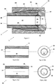
- Figure 1 is a cross sectional view of an end portion of an assembly 1 comprising a terminated composite fluid conduit 2 engaged with a tubular member 14.
- the terminated composite fluid conduit 2 comprises a primary member in the form of a composite fluid conduit 10 and a secondary member in the form of a generally annular composite wedge 20 attached to an outer surface of the fluid conduit 10.
- the fluid conduit 10 comprises an inner layer 16 and an outer layer 18.
- the inner layer 16 is formed from an electrically insulating polyether either ketone (PEEK) matrix material.
- the outer layer 18 is formed from a composite material comprising reinforcing elements in the form of carbon fibres embedded in a PEEK matrix material.
- the inner and outer layers 16, 18 define at interface 28 therebetween.
- the inner layer 16 defines a through bore 22.
- the inner and outer layers 16, 18 comprise flared end sections 24, 26 respectively.
- the flared end section 24 has the effect of gradually increasing the inner and outer diameters of the inner layer 16 as it approaches an end face 34 of the fluid conduit 10.
- the flared end section 26 has the effect of gradually increasing the inner diameter of the outer layer 18 as it approaches the end face 34 of the fluid conduit 10.
- the rate of increase of diameter of the flared end section 24 is the same or substantially similar to the rate of increase of diameter of the flared end section 26.
- the tubular member 14 comprises a corresponding flared section 25 comprising a rate of decrease of diameter.
- the rate of decrease of diameter of flared section 25 may be similar in magnitude to the rate of increase of diameter of flared sections 24, 26.
- the composite wedge 20 comprises a PEEK carbon fibre composite material. Although not shown explicitly in Figure 1 , it should be understood that the composite wedge 20 may comprise an inner PEEK layer and an outer carbon fibre PEEK layer.
- the wedge 20 comprises a frusto-conical portion 30 and a generally cylindrical portion 32. The generally cylindrical portion 32 is located towards the end face 34 of the fluid conduit 10, while the frusto-conical portion 30 is located further from the end face 34 of the fluid conduit 10.
- the terminated fluid conduit 2 further comprises a generally tubular heating element 36 located between the outer layer 18 of the fluid conduit 10 and the wedge 20.
- the heating element 36 is thin-walled and, as will be described in more detail below, is used to weld the outer layer 18 of the fluid conduit 10 and the wedge 20 together.
- the assembly 1 comprises a connection device in the form of a collar member 12 which connects the terminated fluid conduit 2 to the tubular member 14 by engagement with both the tubular member 14 and the wedge 20.
- the collar member 12 defines an outer surface 38 and an inner surface 40.
- the outer surface 38 of the collar member 12 is generally cylindrical, while the inner surface 40 of the collar member 12 is shaped so as to complement the outer profile of the wedge 20.
- the collar member 12 comprises a threaded portion 42 for connection of the terminated fluid conduit 2 to a threaded portion of the tubular member 14.
- the tubular member 14 defines a flared end section 25 at an end face thereof adjacent to the end face 34 of the fluid conduit 10.
- the assembly 1 further comprises a seal member 39 located at the interface between the fluid conduit 10 and the tubular member 14.
- the seal member 39 is generally annular in shape and defines an outer surface which is complementary in shape to an inner surface of the flared end section 24 of the inner layer 16 of the fluid conduit 10 and which is complementary in shape to an inner surface of the flared end section 25 of the tubular member 14.
- the inner diameter of the seal member 39 is similar or substantially similar to the inner diameter of the inner layer 16 of the fluid conduit 10.
- Figures 2(a) and 2(b) show the fluid conduit 10 before formation of the heating element 36.
- Figures 3(a) and 3(b) which do not form part of the invention, show the fluid conduit 10 after formation of the generally tubular heating element 36 directly onto the outer surface of the outer layer 18 of the fluid conduit 10.
- the heating element 36 is disposed such that one end of the heating element 36 is flush with the end face 34 of the fluid conduit 10.
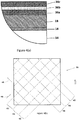
- the heating element 36 comprises a first layer 36a of a PEEK matrix material formed on the outer surface of the outer layer 18 of the fluid conduit 10, a composite layer 36b comprising the PEEK matrix material and a plurality of electrically conductive carbon fibre reinforcing elements formed on top of the first layer 36a of matrix material, and a second layer 36c of the PEEK matrix material formed on top of the composite layer 36b.
- the first layer 36a of PEEK matrix material is formed by wrapping or winding a length of PEEK tape (not shown) on the outer surface of the outer layer 18 of the fluid conduit 10.
- the composite layer 36b is formed by wrapping or winding a single continuous length of PEEK carbon fibre composite tape 45 on top of the first layer 36a of matrix material. Different layers of the composite tape 45 are wound along different directions, for example mutually perpendicular directions as illustrated by arrows 46 and 48 so as to form the composite layer 36b. It should be understood that, although the composite layer 36b of the heating element 36 is formed from a single continuous length of PEEK carbon fibre composite tape 45 such that each carbon fibre reinforcing element of the composite tape 45 extends continuously along the length of the composite tape 45, other composite tape arrangements are possible as will be described in more detail below with reference to Figures 12 and 13 .
- the second layer 36c of PEEK matrix material is formed by wrapping or winding a length of PEEK tape (not shown) on the outer surface of the composite layer 36b.
- FIGs 5(a) and 5(b) which do not form part of the invention, illustrates the welding of the annular PEEK carbon fibre wedge 20 to the fluid conduit 10.
- the annular wedge 20 actually comprises three wedge portions 20a, 20b, 20c.
- Each of the three wedge portions 20a, 20b, 20c account for one third of the material of the annular wedge 20.
- Each of the three wedge portions 20a, 20b, 20c are the same or substantially similar in shape.
- the three wedge portions 20a, 20b, 20c are arranged around, and are held or pressed into engagement with, the heating element 36.
- the ends of the carbon fibres of the composite tape 45 are exposed by burning off some of the PEEK matrix material adjacent to the ends of the composite tape 45, for example using a flame.
- An electrical conductive material in the form of silver paint is applied to the exposed ends of the carbon fibres.
- An electrical source 50 is connected to the painted ends of the carbon fibres using electrical conductors 52.
- Each electrical conductor 52 may, for example, have a clamp, a terminal or the like at one end to facilitate the electrical connection to the painted ends of the carbon fibres.
- the electrical conductors 52 may be electrically connected to the painted ends of the carbon fibres using an electrically conductive adhesive or by soldering or the like.
- the electrical source 50 drives an electrical current through the carbon fibres of the composite tape 45 causing resistive heating of the composite tape 45 until the PEEK matrix material of the heating element 36, the PEEK matrix material of the outer layer 18 of the fluid conduit 10 adjacent the heating element 36, and the PEEK matrix material of the wedge 20 adjacent to the heating element 36 melts.
- the electrical source 50 subsequently reduces or stops the flow of electrical current driven through the composite tape 45 causing the heating element 36 to cool and causing the PEEK matrix material of the heating element 36 to fuse or bond with the PEEK matrix material of the outer layer 18 of the fluid conduit 10 and with the PEEK matrix material of the wedge 20.
- the electrical source 50 may drive an alternating current (AC) or a direct current (DC) through the carbon fibres of the composite tape 45.
- annular recess 54 is triangular in cross section.
- Figure 6(b) illustrates a close-up view of the annular recess 54.
- the annular recess 54 is formed in the region of the interface 28 between the inner layer 16 and the outer layer 18 of the fluid conduit 10 so as to define a radially inner end portion 56a of the fluid conduit 10 and a radially outer end portion 56b of the fluid conduit 10.
- the annular recess 54 may be formed by any appropriate method, for example, by machining, melting or the like.
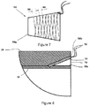
- a further heating element 58 shown in Figure 7 is used to weld the radially inner end portion 56a of the fluid conduit 10 and the radially outer end portion 56b of the fluid conduit 10 together.
- the further heating element 58 has a similar composite structure to the heating element 36. More specifically, the further heating element 58 comprises a frusto-conical PEEK substrate 58a, a PEEK carbon fibre composite layer formed on or around the PEEK substrate 58a and an outer PEEK layer formed around the composite PEEK carbon fibre composite layer.
- the PEEK carbon fibre composite layer is formed by wrapping or winding a single length of PEEK carbon fibre composite tape 66 on top of the PEEK substrate 58a. Different layers of the composite tape 66 are wound along different directions to form the PEEK carbon fibre composite layer.
- the outer PEEK layer is formed by wrapping or winding a length of PEEK tape (not shown) on the outer surface of the PEEK carbon fibre composite layer.
- the further heating element 58 is inserted into the annular recess 54 formed in the end face 34 of the fluid conduit 10.
- the frusto-conical outer surface of the further heating element 58 is configured to engage an inner surface of the radially outer end portion 56b of the fluid conduit 10.
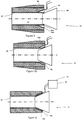
- the method continues with the thermoforming of the radially inner end portion 56a of the fluid conduit 10 using a moulding tool 60 inserted into the through bore 22 of the fluid conduit 10 at an end of the through bore 22 adjacent to the end face 34.
- the moulding tool 60 Before insertion into through bore 22, the moulding tool 60 is heated, for example by a flame or heated air. A force in the direction of arrow 72 is applied to the moulding tool 60 so as to deform or splay the inner end portion 56a of the fluid conduit 10 radially outwardly as shown in Figure 10 until the inner end portion 56a of the fluid conduit 10 engages a radially inner surface of the further heating element 58 as shown in Figure 11 .
- the electrical source 50 is connected to the further heating element 58 by the electrical conductors 52.
- the electrical source 50 drives an electrical current through the carbon fibres of the composite tape 66 of the further heating element 58 to resistively heat and melt the PEEK matrix material of the further heating element 58 with the adjacent PEEK matrix material of the inner end portion 56a of the fluid conduit 10 and with the adjacent PEEK matrix material of the outer end portion 56b of the fluid conduit 10.
- the electrical source 50 subsequently reduces or discontinues the flow of the electrical current to permit the PEEK matrix material of the further heating element 58, the PEEK matrix material of the inner end portion 56a of the fluid conduit 10, and the PEEK matrix material of the outer end portion 56b of the fluid conduit 10 to solidify and fuse thereby bonding the inner end portion 56a of the fluid conduit 10 and the outer end portion 56b of the fluid conduit 10 to the further heating element 58.
- Figure 12 which does not form part of the invention, illustrates an alternative method for welding the wedge portions 20a, 20b, 20c of the wedge 20 to the fluid conduit 10.
- a generally tubular heating element 136 is formed in situ on the outer surface of the outer layer 18 of the fluid conduit 10.
- the heating element 136 comprises a first layer of a PEEK matrix material formed on the outer surface of the outer layer 18 of the fluid conduit 10, a composite layer comprising the PEEK matrix material and a plurality of electrically conductive carbon fibre reinforcing elements formed on top of the first layer of PEEK matrix material, and a second layer of the PEEK matrix material formed on top of the composite layer.
- the first layer of PEEK matrix material of the heating element 136 is formed by wrapping or winding a length of PEEK tape (not shown) on the outer surface of the outer layer 18 of the fluid conduit 10.
- the composite layer of the heating element 136 shown in Figure 13 is formed by wrapping or winding separate electrically distinct PEEK carbon fibre composite tapes 145a, 145b, 145c, 145d, 145e, 145f on top of the first layer of PEEK matrix material.
- some composite tapes 145a, 145b, 145c may be wound along one direction 146, whilst other composite tapes 145d, 145e, 145f may be wound along a different direction such as a perpendicular direction 148 so that each composite tape 145a, 145b, 145c, 145d, 145e, 145f may overlap one or more of the other composite tapes in a plurality of overlapping regions.
- the carbon fibres of each composite tape 145a, 145b, 145c, 145d, 145e, 145f may converge, overlap and/or engage with the carbon fibres of one or more of the other composite tapes in each overlapping region.
- each overlapping region may be considered to be a region of convergence of the carbon fibres of at least two different composite tapes.
- the second layer of PEEK matrix material of the heating element 136 is formed by wrapping or winding a length of PEEK tape (not shown) on the outer surface of the PEEK carbon fibre composite layer.
- an electrical source 150 is connected to the heating element 136 by electrical conductors 152. More specifically, both ends of each composite tape 145a, 145b, 145c, 145d, 145e, 145f are connected to the electrical source 150 by a corresponding pair of electrical conductors 152.
- the electrical source 150 is configured to drive an electrical current through each composite tape 145a, 145b, 145c, 145d, 145e, 145f independently of the other composite tapes.
- the electrical source 150 may, for example, comprise a switch or demultiplexer arrangement (not shown) for this purpose. This may permit different regions of the heating element to be heated differently.
- driving an electrical current through composite tapes 145b and 145d more frequently than driving an electrical current through the other composite tapes 145a, 145c, 145e, and 145f may result in greater resistive heating in the vicinity of composite tapes 145b and 145d and, in particular, may result in greater resistive heating in a region of overlap 147 of the composite tapes 145b and 145d.
- the heating element 136 may allow a greater degree of heating in selected areas of the heating element 136 such as those areas of the heating element 136 which cool most rapidly.
- the electrical source 150 may be operated so as to preferentially heat an annular region of the heating element 136 which is located generally midway axially between the ends of the wedge 20. This may provide a more uniform temperature distribution during welding and may result in a more uniform bond between the heating element 136 and both the wedge 20 and the fluid conduit 10.
- the electrical source 150 may drive an alternating current (AC) or a direct current (DC) through the carbon fibres of the composite tapes 145a, 145b, 145c, 145d, 145e, 145f.
- AC alternating current
- DC direct current
- driving AC through the carbon fibres of one tape may induce the flow of AC in the flow of carbon fibres in a different adjacent tape.
- driving AC through the carbon fibres of one tape may induce the flow of AC in the flow of carbon fibres in a region of overlap of the one tape with a different tape in a previous or a subsequent layer of composite tape.
- the electrical source 150 may be configured to drive an electrical current through two or more of the composite tapes 145a, 145b, 145c, 145d, 145e, 145f at the same time.
- the heating element may include or incorporate a temperature sensor such as a Fibre Bragg Grating (FBG), a resistance temperature detector (RTD), a thermistor, a thermocouple or the like. Incorporating a temperature sensor into the heating element may allow greater control over the heating process. This may, for example, allow greater control over the temperature and/or the temperature distribution. This may, in turn, allow greater control over the welding process leading to improved weld strength.
- Figure 14 which does not form part of the invention, shows a first alternative fluid conduit arrangement comprising a composite fluid conduit 210 and a composite annular wedge 220 after welding of the composite annular wedge 220 to the composite fluid conduit 210.
- the fluid conduit 210 comprises a PEEK inner layer 216 and a PEEK carbon fibre outer layer 218.
- the composite annular wedge 220 comprises a PEEK carbon fibre composite material.
- the composite annular wedge 220 may comprise a PEEK inner layer and a PEEK carbon fibre outer layer.
- the fluid conduit 210 defines a tapered outer surface having a diameter which decreases towards an end face of the fluid conduit 210 and the annular wedge 220 defines a complementary tapered inner surface having a diameter which decreases towards the end of fluid conduit 210.
- Figure 15 shows a second alternative fluid conduit arrangement comprising a composite fluid conduit 310 and a composite annular wedge 320 after welding of the composite annular wedge 320 to the composite fluid conduit 310.
- the fluid conduit 310 comprises a PEEK inner layer 316 and a PEEK carbon fibre outer layer 318.
- the composite annular wedge 320 comprises a PEEK carbon fibre composite material.
- the composite annular wedge 320 may comprise a PEEK inner layer and a PEEK carbon fibre outer layer.
- the fluid conduit 310 defines a tapered outer surface having a diameter which increases towards an end face of the fluid conduit 310 and the annular wedge 320 defines a complementary tapered inner surface having a diameter which increases towards the end of fluid conduit 310.
- Figures 16(a) and 16(b) which do not form part of the invention, show a third alternative fluid conduit arrangement comprising a composite fluid conduit 410 and a composite annular wedge 420 after welding of the composite annular wedge 420 to the composite fluid conduit 410.
- the fluid conduit 410 comprises a PEEK inner layer 416 and a PEEK carbon fibre outer layer 418.
- the composite annular wedge 420 comprises a PEEK carbon fibre composite material.
- the composite sleeve 420 may comprise a PEEK inner layer and a PEEK carbon fibre outer layer.
- the composite annular wedge 420 is unitary and defines a plurality of slots 422.
- Each slot 422 is aligned parallel to the longitudinal axis of the composite annular wedge 420, and extends part way along a length of the composite annular wedge 420 from the frusto-conical end 430 of the composite annular wedge 420 towards an end face 434 of the fluid conduit 410.
- the plurality of slots 422 have a uniform circumferential distribution about the composite annular wedge 420, shown best in Figure 16(b) .
- the slots 422 reduce the circumferential stiffness of a section of the composite annular wedge 420 adjacent the frusto-conical end 430 of the composite annular wedge 420. This may permit an inner surface of the section of the composite annular wedge 420 adjacent the frusto-conical end 430 to be more readily compressed into compliance with an outer surface of the composite fluid conduit 410 to improve the uniformity of contact therebetween.
- Figures 17(a) - 17(c) which do not form part of the invention, show a fourth alternative fluid conduit arrangement comprising a composite fluid conduit 510 and a composite annular wedge 520 after welding of the composite annular wedge 520 to the composite fluid conduit 510.
- the fluid conduit 510 comprises a PEEK inner layer 516 and a PEEK carbon fibre outer layer 518.
- the composite annular wedge 520 comprises a PEEK carbon fibre composite material.
- the composite annular wedge 520 may comprise a PEEK inner layer and a PEEK carbon fibre outer layer.
- the composite annular wedge 520 is unitary and defines a plurality of slots 522.
- the plurality of slots 522 are aligned parallel to the longitudinal axis of the composite annular wedge 520 and the plurality of slots 522 have a uniform circumferential distribution about the composite annular wedge 520, shown best in Figure 17(a) , which does not form part of the invention.
- adjacent slots 522 of the composite annular wedge 520 extend from different ends of the composite annular wedge 520 as shown in the longitudinal cross-section on AA shown in Figure 17(b) , which does not form part of the invention, and the longitudinal cross-section on BB shown in Figure 17(c) , which does not form part of the invention.
- a first set of alternate slots 522 extends from the frusto-conical end 530 of the composite annular wedge 520 towards an end face 534 of the fluid conduit 510, whilst a second set of alternate slots 522 extends from the end face 534 of the fluid conduit 510 towards the frusto-conical end 530 of the composite annular wedge 520.
- the first set of alternate slots 522 and the second set of alternate slots 522 overlap in longitudinal extent in a central section of the composite annular wedge 520.
- the slots 522 reduce the circumferential stiffness of the composite annular wedge 520 along the whole length of the composite annular wedge 520, particularly in the central section where the first and second sets of alternate slots 522 overlap in longitudinal extent. This may permit an inner surface of the composite annular wedge 520 to be more readily compressed into compliance with an outer surface of the composite fluid conduit 510 to improve the uniformity of contact therebetween along the whole length of the composite annular wedge 520, particularly in the central section.
- the arrangement of the plurality of slots is not restricted to those shown in Figures 16(a), 16(b) and 17(a) - 17(c) .
- the number of slots may be greater or fewer than eight.
- the circumferential distribution of the slots around the composite annular wedge may be different, for example nonuniform.
- the slots may instead all extend from the end face 434 of the fluid conduit 410.
- the slots may not extend to either end of the composite annular wedge.
- the slots may be located centrally along the length of the composite annular wedge.
- One or more of the slots may extend only part way through a thickness of the wall of the composite annular wedge. One or more of the slots may extend along the whole of the length of the composite annular wedge. Different slots may have the same longitudinal extent. Different slots may have different longitudinal extents.
Landscapes
- Engineering & Computer Science (AREA)
- Mechanical Engineering (AREA)
- Physics & Mathematics (AREA)
- Thermal Sciences (AREA)
- General Engineering & Computer Science (AREA)
- Lining Or Joining Of Plastics Or The Like (AREA)
Description
- A method for joining a primary member such as a composite tubular and a secondary member such as a component is described herein. The method may be suitable for use in particular, though not exclusively, for terminating a composite tubular.
- It is known to use composite tubulars in place of steel tubulars for various reasons. For example, a composite tubular may be capable of withstanding greater strains and may be lighter than an equivalently sized steel tubular. In addition, the manufacturing process for composite tubulars may allow for different portions of the tubular to be constructed differently. For example, different portions of a composite tubular may be reinforced differently or may permit an additional feature or device, such as an electrical device, to be at least partially embedded within or attached to a wall of the composite tubular.
- When terminating a composite tubular such as a composite fluid conduit for connection to a further member such as a further fluid conduit, it may be desirable to form a built-up region having a greater wall thickness at or adjacent to an end of the composite tubular. This may be achieved by applying additional layers of composite tape to an outer surface of the composite tubular at or adjacent to the end of the composite tubular. The resulting built-up region may subsequently be machined to a desired geometry. However, such known techniques for locally increasing wall thickness at or adjacent to the end of a composite tubular may be time-consuming and/or costly.
- With reference to
US 5,500,510 A , it is known to connect thermoplastic resin pipes to one another by a fusion process involving a heating element which comprises an electrically insulating matrix material and electrically conductive reinforcing elements extending through the matrix. Further joining processes using heating elements are described inWO 89/12545 A1 EP 0 924 054 A2 ,US 7 034 251 B1 andGB 2 518 006 A - The invention relates to a method for joining primary and secondary members as defined in
claim 1. - The primary and secondary members are defined by different portions of a unitary member. The primary member is defined by a primary portion of the unitary member and the secondary member is defined by a secondary portion of the unitary member. The method may comprise shaping the unitary member, for example by removing material from the unitary member, so as to define the primary and secondary portions. For example, the method may comprise removing material of the unitary member by machining, melting or the like.
- The method comprises forming a recess in the unitary member. The recess defines the primary portion of the unitary member to one side of the recess and the secondary portion of the unitary member to the other side of the recess.
- The method comprises inserting the heating element into the recess.
- The method comprises compressing the heating element between the primary and secondary portions of the unitary member.
- The primary member may be defined by a primary end portion of the unitary member and the secondary member may be defined by a secondary end portion of the unitary member.
- The unitary member may be a tubular member.
- The method may comprise forming an annular recess in an end face of the tubular member. The annular recess may define a primary annular end portion of the tubular member radially inwardly of the annular recess and a secondary annular end portion of the tubular member radially outwardly of the annular recess.
- The method may comprise forming the annular recess at one end of a generally cylindrical interface between an inner layer of the tubular member and an adjacent layer of the tubular member. The method may comprise forming the annular recess with an outwardly flared profile.
- The method may comprise inserting the heating element into the annular recess. The heating element may be configured for insertion into the annular recess. The heating element may be configured for engaging the primary and/or secondary annular end portions of the tubular member. The heating element may be thin-walled. The heating element may define a conical surface for engaging a flared surface of the annular recess.
- The method may comprise inserting a moulding tool into a through bore defined by the tubular member. The moulding tool may define a conical moulding surface. The moulding tool may be frusto-conical in shape.
- The method may comprise heating the moulding tool before or during insertion into the through bore of the tubular member. The moulding tool may be heated by any appropriate means. For example, the moulding tool may be heated by contact with a heat source such as a flame, heated air or the like. The moulding tool may be heated electrically. The method may comprise inserting the moulding tool into the through bore of the tubular member adjacent to the annular recess.
- The method may comprise forcing the moulding tool against the primary annular end portion of the tubular member so as to deform the primary annular end portion of the tubular member radially outwardly. The method may comprise forcing the moulding tool against the primary annular end portion of the tubular member so as to deform the primary annular end portion of the tubular member into the annular recess. The method may comprise forcing the moulding tool against the primary annular end portion of the tubular member so as to deform the primary annular end portion of the tubular member into engagement with the heating element. The method may comprise forcing the moulding tool against the primary annular end portion of the tubular member so as to bring the primary and secondary annular end portions of the tubular member into engagement with the heating element.
- The heating element may comprise a carbon fibre, glass fibre or metal reinforcing element. The heating element may comprise different types of reinforcing elements. For example, the heating element may comprise one or more carbon fibre reinforcing elements and one or more glass fibre reinforcing elements.
- The primary member may comprise at least one reinforcing element. The primary member may comprise a composite material comprising a matrix material and at least one reinforcing element.
- The secondary member may comprise at least one reinforcing element. The secondary member may comprise a composite material comprising a matrix material and at least one reinforcing element.
- Each reinforcing element may comprise, for example, a carbon fibre, a metallic strand or the like.
- The matrix material of at least one of the heating element, the primary member and the secondary member may comprise a polymer. The matrix material of at least one of the heating element, the primary member and the secondary member may comprise a material such as polyether ether ketone (PEEK), polyaryl ether ketone (PAEK), polyvinylidene diflouride (PVDF), polyphenylene sulphide (PPS) or the like.
- The matrix material of the primary member, the secondary member and the heating element may be same matrix material.
- The primary and/or secondary members may comprise a metal such as steel, aluminium or the like.
- Methods and apparatus will now be further described with reference to the following drawings of which:
- Figure 1
- is a longitudinal cross-section of an assembly comprising a terminated composite fluid conduit engaged with a tubular member;
- Figure 2(a)
- which does not form part of the invention, is a longitudinal cross-section of an end portion of a composite fluid conduit before termination;
- Figure 2(b)
- which does not form part of the invention, is an end view of the fluid conduit of
Figure 2(a) ; - Figure 3(a)
- which does not form part of the invention, is a longitudinal cross-section of the end portion of a composite fluid conduit arrangement comprising the composite fluid conduit of
Figure 2(a) and a heating element formed on an external surface of the composite fluid conduit; - Figure 3(b)
- which does not form part of the invention, is an end view of the composite fluid conduit arrangement of
Figure 3(a) ; - Figure 4(a)
- which does not form part of the invention, shows a detail of the longitudinal cross-section of an end portion of the heating element of
Figures 3(a) and 3(b) ; - Figure 4(b)
- which does not form part of the invention, shows the arrangement of composite tape in a region of the heating element of
Figures 3(a) and 3(b) ; - Figure 5(a)
- which does not form part of the invention, is a longitudinal cross-section of the end portion of a composite fluid conduit arrangement during welding of build-up wedge components to the fluid conduit of
Figures 2(a) and 2(b) using the heating element ofFigures 4(a) and 4(b) ; - Figure 5(b)
- which does not form part of the invention, is an end view of the fluid conduit arrangement of
Figure 5(a) ; - Figure 6(a)
- is a longitudinal cross-section of the end portion of the composite fluid conduit arrangement of
Figures 5(a) and 5(b) after formation of a recess in an end face of the composite fluid conduit arrangement; - Figure 6(b)
- shows a detail of the longitudinal cross-section of the recess of
Figure 6(a) ; - Figure 7
- is a side-elevation of a further heating element;
- Figure 8
- is a longitudinal cross-section of the end portion of the composite fluid conduit arrangement of
Figures 6(a) and 6(b) after insertion of the further heating element ofFigure 7 into the recess; - Figure 9
- is a longitudinal cross-section of the end portion of the composite fluid conduit arrangement and of a moulding tool;
- Figure 10
- is a longitudinal cross-section of the end portion of the composite fluid conduit arrangement during thermoforming of an inner end portion of the fluid conduit using the moulding tool;
- Figure 11
- is a longitudinal cross-section of the end portion of the composite fluid conduit arrangement during welding of the inner end portion of the fluid conduit to an outer end portion of the fluid conduit;
- Figure 12
- which does not form part of the invention, is a longitudinal cross-section of an end portion of a composite fluid conduit arrangement during welding of build-up wedge components to a fluid conduit using an alternative heating element;
- Figure 13
- which does not form part of the invention, shows the arrangement of different lengths of composite tape in a region of the alternative heating element of
Figure 12 ; - Figure 14
- which does not form part of the invention, is longitudinal cross-section of an end portion of a first alternative composite fluid conduit arrangement;
- Figure 15
- which does not form part of the invention, is a longitudinal cross-section of an end portion of a second alternative composite fluid conduit arrangement;
- Figure 16(a)
- which does not form part of the invention, is a longitudinal cross-section of an end portion of a third alternative composite fluid conduit arrangement;
- Figure 16(b)
- which does not form part of the invention, is an end view of the third alternative composite fluid conduit arrangement of
Figure 16(a) ; - Figure 17(a)
- which does not form part of the invention, is an end view of a fourth alternative composite fluid conduit arrangement;
- Figure 17(b)
- which does not form part of the invention, is a longitudinal cross-section on AA of an end portion of the fourth alternative composite fluid conduit arrangement of
Figure 17(a) ; and - Figure 17(c)
- which does not form part of the invention, is a longitudinal cross-section on BB of an end portion of the fourth alternative composite fluid conduit arrangement of
Figure 17(a) . -
Figure 1 is a cross sectional view of an end portion of anassembly 1 comprising a terminated compositefluid conduit 2 engaged with atubular member 14. The terminated compositefluid conduit 2 comprises a primary member in the form of a compositefluid conduit 10 and a secondary member in the form of a generally annularcomposite wedge 20 attached to an outer surface of thefluid conduit 10. - The
fluid conduit 10 comprises aninner layer 16 and anouter layer 18. Theinner layer 16 is formed from an electrically insulating polyether either ketone (PEEK) matrix material. Theouter layer 18 is formed from a composite material comprising reinforcing elements in the form of carbon fibres embedded in a PEEK matrix material. The inner andouter layers interface 28 therebetween. Theinner layer 16 defines a throughbore 22. - The inner and
outer layers end sections end section 24 has the effect of gradually increasing the inner and outer diameters of theinner layer 16 as it approaches anend face 34 of thefluid conduit 10. The flaredend section 26 has the effect of gradually increasing the inner diameter of theouter layer 18 as it approaches theend face 34 of thefluid conduit 10. The rate of increase of diameter of the flaredend section 24 is the same or substantially similar to the rate of increase of diameter of the flaredend section 26. Thetubular member 14 comprises a corresponding flared section 25 comprising a rate of decrease of diameter. The rate of decrease of diameter of flared section 25 may be similar in magnitude to the rate of increase of diameter of flaredsections - The
composite wedge 20 comprises a PEEK carbon fibre composite material. Although not shown explicitly inFigure 1 , it should be understood that thecomposite wedge 20 may comprise an inner PEEK layer and an outer carbon fibre PEEK layer. Thewedge 20 comprises a frusto-conical portion 30 and a generallycylindrical portion 32. The generallycylindrical portion 32 is located towards theend face 34 of thefluid conduit 10, while the frusto-conical portion 30 is located further from theend face 34 of thefluid conduit 10. - The terminated
fluid conduit 2 further comprises a generallytubular heating element 36 located between theouter layer 18 of thefluid conduit 10 and thewedge 20. Theheating element 36 is thin-walled and, as will be described in more detail below, is used to weld theouter layer 18 of thefluid conduit 10 and thewedge 20 together. - The
assembly 1 comprises a connection device in the form of acollar member 12 which connects the terminatedfluid conduit 2 to thetubular member 14 by engagement with both thetubular member 14 and thewedge 20. Thecollar member 12 defines anouter surface 38 and aninner surface 40. Theouter surface 38 of thecollar member 12 is generally cylindrical, while theinner surface 40 of thecollar member 12 is shaped so as to complement the outer profile of thewedge 20. Thecollar member 12 comprises a threadedportion 42 for connection of the terminatedfluid conduit 2 to a threaded portion of thetubular member 14. - The
tubular member 14 defines a flared end section 25 at an end face thereof adjacent to theend face 34 of thefluid conduit 10. - The
assembly 1 further comprises aseal member 39 located at the interface between thefluid conduit 10 and thetubular member 14. Theseal member 39 is generally annular in shape and defines an outer surface which is complementary in shape to an inner surface of the flaredend section 24 of theinner layer 16 of thefluid conduit 10 and which is complementary in shape to an inner surface of the flared end section 25 of thetubular member 14. The inner diameter of theseal member 39 is similar or substantially similar to the inner diameter of theinner layer 16 of thefluid conduit 10. - A method of forming the terminated
fluid conduit 2 ofFigure 1 will now be described with reference toFigures 2(a) - 11 , which does not form part of the invention. -
Figures 2(a) and 2(b) show thefluid conduit 10 before formation of theheating element 36. -
Figures 3(a) and 3(b) , which do not form part of the invention, show thefluid conduit 10 after formation of the generallytubular heating element 36 directly onto the outer surface of theouter layer 18 of thefluid conduit 10. Theheating element 36 is disposed such that one end of theheating element 36 is flush with theend face 34 of thefluid conduit 10. - As shown in
Figure 4(a) , which does not form part of the invention, theheating element 36 comprises afirst layer 36a of a PEEK matrix material formed on the outer surface of theouter layer 18 of thefluid conduit 10, acomposite layer 36b comprising the PEEK matrix material and a plurality of electrically conductive carbon fibre reinforcing elements formed on top of thefirst layer 36a of matrix material, and asecond layer 36c of the PEEK matrix material formed on top of thecomposite layer 36b. - The
first layer 36a of PEEK matrix material is formed by wrapping or winding a length of PEEK tape (not shown) on the outer surface of theouter layer 18 of thefluid conduit 10. - As shown in
Figure 4(b) , which does not form part of the invention, thecomposite layer 36b is formed by wrapping or winding a single continuous length of PEEK carbon fibrecomposite tape 45 on top of thefirst layer 36a of matrix material. Different layers of thecomposite tape 45 are wound along different directions, for example mutually perpendicular directions as illustrated byarrows composite layer 36b. It should be understood that, although thecomposite layer 36b of theheating element 36 is formed from a single continuous length of PEEK carbon fibrecomposite tape 45 such that each carbon fibre reinforcing element of thecomposite tape 45 extends continuously along the length of thecomposite tape 45, other composite tape arrangements are possible as will be described in more detail below with reference toFigures 12 and13 . - The
second layer 36c of PEEK matrix material is formed by wrapping or winding a length of PEEK tape (not shown) on the outer surface of thecomposite layer 36b. -
Figures 5(a) and 5(b) , which do not form part of the invention, illustrates the welding of the annular PEEKcarbon fibre wedge 20 to thefluid conduit 10. As shown inFigure 5(b) , theannular wedge 20 actually comprises threewedge portions wedge portions annular wedge 20. Each of the threewedge portions wedge portions heating element 36. - The ends of the carbon fibres of the
composite tape 45 are exposed by burning off some of the PEEK matrix material adjacent to the ends of thecomposite tape 45, for example using a flame. An electrical conductive material in the form of silver paint is applied to the exposed ends of the carbon fibres. Anelectrical source 50 is connected to the painted ends of the carbon fibres usingelectrical conductors 52. Eachelectrical conductor 52 may, for example, have a clamp, a terminal or the like at one end to facilitate the electrical connection to the painted ends of the carbon fibres. Alternatively, theelectrical conductors 52 may be electrically connected to the painted ends of the carbon fibres using an electrically conductive adhesive or by soldering or the like. - In use, the
electrical source 50 drives an electrical current through the carbon fibres of thecomposite tape 45 causing resistive heating of thecomposite tape 45 until the PEEK matrix material of theheating element 36, the PEEK matrix material of theouter layer 18 of thefluid conduit 10 adjacent theheating element 36, and the PEEK matrix material of thewedge 20 adjacent to theheating element 36 melts. Theelectrical source 50 subsequently reduces or stops the flow of electrical current driven through thecomposite tape 45 causing theheating element 36 to cool and causing the PEEK matrix material of theheating element 36 to fuse or bond with the PEEK matrix material of theouter layer 18 of thefluid conduit 10 and with the PEEK matrix material of thewedge 20. Theelectrical source 50 may drive an alternating current (AC) or a direct current (DC) through the carbon fibres of thecomposite tape 45. - As shown in
Figure 6(a) , the method of forming the terminatedfluid conduit 2 continues with the formation of anannular recess 54 in theend face 34 of thefluid conduit 10. Theannular recess 54 is triangular in cross section.Figure 6(b) illustrates a close-up view of theannular recess 54. Theannular recess 54 is formed in the region of theinterface 28 between theinner layer 16 and theouter layer 18 of thefluid conduit 10 so as to define a radiallyinner end portion 56a of thefluid conduit 10 and a radiallyouter end portion 56b of thefluid conduit 10. Theannular recess 54 may be formed by any appropriate method, for example, by machining, melting or the like. - As will be described in more detail below, a
further heating element 58 shown inFigure 7 is used to weld the radiallyinner end portion 56a of thefluid conduit 10 and the radiallyouter end portion 56b of thefluid conduit 10 together. Thefurther heating element 58 has a similar composite structure to theheating element 36. More specifically, thefurther heating element 58 comprises a frusto-conical PEEK substrate 58a, a PEEK carbon fibre composite layer formed on or around thePEEK substrate 58a and an outer PEEK layer formed around the composite PEEK carbon fibre composite layer. The PEEK carbon fibre composite layer is formed by wrapping or winding a single length of PEEK carbon fibrecomposite tape 66 on top of thePEEK substrate 58a. Different layers of thecomposite tape 66 are wound along different directions to form the PEEK carbon fibre composite layer. The outer PEEK layer is formed by wrapping or winding a length of PEEK tape (not shown) on the outer surface of the PEEK carbon fibre composite layer. - In the next step of the method shown in
Figure 8 , thefurther heating element 58 is inserted into theannular recess 54 formed in theend face 34 of thefluid conduit 10. As shown inFigure 8 , the frusto-conical outer surface of thefurther heating element 58 is configured to engage an inner surface of the radiallyouter end portion 56b of thefluid conduit 10. - As shown in
Figures 9 and 10 the method continues with the thermoforming of the radiallyinner end portion 56a of thefluid conduit 10 using amoulding tool 60 inserted into the throughbore 22 of thefluid conduit 10 at an end of the throughbore 22 adjacent to theend face 34. Before insertion into throughbore 22, themoulding tool 60 is heated, for example by a flame or heated air. A force in the direction ofarrow 72 is applied to themoulding tool 60 so as to deform or splay theinner end portion 56a of thefluid conduit 10 radially outwardly as shown inFigure 10 until theinner end portion 56a of thefluid conduit 10 engages a radially inner surface of thefurther heating element 58 as shown inFigure 11 . - With the
inner end portion 56a of thefluid conduit 10 in engagement with the radially inner surface of thefurther heating element 58 as shown inFigure 11 , theelectrical source 50 is connected to thefurther heating element 58 by theelectrical conductors 52. Theelectrical source 50 drives an electrical current through the carbon fibres of thecomposite tape 66 of thefurther heating element 58 to resistively heat and melt the PEEK matrix material of thefurther heating element 58 with the adjacent PEEK matrix material of theinner end portion 56a of thefluid conduit 10 and with the adjacent PEEK matrix material of theouter end portion 56b of thefluid conduit 10. Theelectrical source 50 subsequently reduces or discontinues the flow of the electrical current to permit the PEEK matrix material of thefurther heating element 58, the PEEK matrix material of theinner end portion 56a of thefluid conduit 10, and the PEEK matrix material of theouter end portion 56b of thefluid conduit 10 to solidify and fuse thereby bonding theinner end portion 56a of thefluid conduit 10 and theouter end portion 56b of thefluid conduit 10 to thefurther heating element 58. -
Figure 12 , which does not form part of the invention, illustrates an alternative method for welding thewedge portions wedge 20 to thefluid conduit 10. As for the method described with reference toFigures 2(a) to 4(b) , a generallytubular heating element 136 is formed in situ on the outer surface of theouter layer 18 of thefluid conduit 10. - Like the
heating element 36 ofFigures 4(a) and 4(b) , theheating element 136 comprises a first layer of a PEEK matrix material formed on the outer surface of theouter layer 18 of thefluid conduit 10, a composite layer comprising the PEEK matrix material and a plurality of electrically conductive carbon fibre reinforcing elements formed on top of the first layer of PEEK matrix material, and a second layer of the PEEK matrix material formed on top of the composite layer. - Like the
heating element 36 ofFigures 4(a) and 4(b) , the first layer of PEEK matrix material of theheating element 136 is formed by wrapping or winding a length of PEEK tape (not shown) on the outer surface of theouter layer 18 of thefluid conduit 10. - However, unlike the
heating element 36 ofFigures 4(a) and 4(b) , the composite layer of theheating element 136 shown inFigure 13 is formed by wrapping or winding separate electrically distinct PEEK carbonfibre composite tapes Figure 13 , somecomposite tapes direction 146, whilst othercomposite tapes perpendicular direction 148 so that eachcomposite tape composite tape - Like the
heating element 36 ofFigures 4(a) and 4(b) , the second layer of PEEK matrix material of theheating element 136 is formed by wrapping or winding a length of PEEK tape (not shown) on the outer surface of the PEEK carbon fibre composite layer. - With reference to
Figure 12 , anelectrical source 150 is connected to theheating element 136 byelectrical conductors 152. More specifically, both ends of eachcomposite tape electrical source 150 by a corresponding pair ofelectrical conductors 152. Theelectrical source 150 is configured to drive an electrical current through eachcomposite tape electrical source 150 may, for example, comprise a switch or demultiplexer arrangement (not shown) for this purpose. This may permit different regions of the heating element to be heated differently. For example, with reference toFigure 13 , which does not form part of the invention, driving an electrical current throughcomposite tapes composite tapes composite tapes overlap 147 of thecomposite tapes heating element 136 may allow a greater degree of heating in selected areas of theheating element 136 such as those areas of theheating element 136 which cool most rapidly. In particular, theelectrical source 150 may be operated so as to preferentially heat an annular region of theheating element 136 which is located generally midway axially between the ends of thewedge 20. This may provide a more uniform temperature distribution during welding and may result in a more uniform bond between theheating element 136 and both thewedge 20 and thefluid conduit 10. Theelectrical source 150 may drive an alternating current (AC) or a direct current (DC) through the carbon fibres of thecomposite tapes - One of ordinary skill in the art will appreciate that various modifications may be made to the foregoing apparatus and methods. For example, with reference to the
heating element 136, theelectrical source 150 may be configured to drive an electrical current through two or more of thecomposite tapes -
Figure 14 , which does not form part of the invention, shows a first alternative fluid conduit arrangement comprising a compositefluid conduit 210 and a compositeannular wedge 220 after welding of the compositeannular wedge 220 to the compositefluid conduit 210. Thefluid conduit 210 comprises a PEEKinner layer 216 and a PEEK carbon fibreouter layer 218. The compositeannular wedge 220 comprises a PEEK carbon fibre composite material. For example, the compositeannular wedge 220 may comprise a PEEK inner layer and a PEEK carbon fibre outer layer. Unlike the composite fluid conduit arrangement ofFigures 5(a) and 5(b) , however, thefluid conduit 210 defines a tapered outer surface having a diameter which decreases towards an end face of thefluid conduit 210 and theannular wedge 220 defines a complementary tapered inner surface having a diameter which decreases towards the end offluid conduit 210. -
Figure 15 , which does not form part of the invention, shows a second alternative fluid conduit arrangement comprising a compositefluid conduit 310 and a compositeannular wedge 320 after welding of the compositeannular wedge 320 to the compositefluid conduit 310. Thefluid conduit 310 comprises a PEEKinner layer 316 and a PEEK carbon fibreouter layer 318. The compositeannular wedge 320 comprises a PEEK carbon fibre composite material. For example, the compositeannular wedge 320 may comprise a PEEK inner layer and a PEEK carbon fibre outer layer. Unlike the composite fluid conduit arrangement ofFigures 5(a) and 5(b) , however, thefluid conduit 310 defines a tapered outer surface having a diameter which increases towards an end face of thefluid conduit 310 and theannular wedge 320 defines a complementary tapered inner surface having a diameter which increases towards the end offluid conduit 310. -
Figures 16(a) and 16(b) , which do not form part of the invention, show a third alternative fluid conduit arrangement comprising a compositefluid conduit 410 and a compositeannular wedge 420 after welding of the compositeannular wedge 420 to the compositefluid conduit 410. Thefluid conduit 410 comprises a PEEKinner layer 416 and a PEEK carbon fibreouter layer 418. Like the compositeannular wedges annular wedge 420 comprises a PEEK carbon fibre composite material. For example, thecomposite sleeve 420 may comprise a PEEK inner layer and a PEEK carbon fibre outer layer. However, unlike the compositeannular wedges annular wedge 420 is unitary and defines a plurality ofslots 422. Eachslot 422 is aligned parallel to the longitudinal axis of the compositeannular wedge 420, and extends part way along a length of the compositeannular wedge 420 from the frusto-conical end 430 of the compositeannular wedge 420 towards anend face 434 of thefluid conduit 410. The plurality ofslots 422 have a uniform circumferential distribution about the compositeannular wedge 420, shown best inFigure 16(b) . Theslots 422 reduce the circumferential stiffness of a section of the compositeannular wedge 420 adjacent the frusto-conical end 430 of the compositeannular wedge 420. This may permit an inner surface of the section of the compositeannular wedge 420 adjacent the frusto-conical end 430 to be more readily compressed into compliance with an outer surface of the compositefluid conduit 410 to improve the uniformity of contact therebetween. -
Figures 17(a) - 17(c) , which do not form part of the invention, show a fourth alternative fluid conduit arrangement comprising a compositefluid conduit 510 and a compositeannular wedge 520 after welding of the compositeannular wedge 520 to the compositefluid conduit 510. Thefluid conduit 510 comprises a PEEKinner layer 516 and a PEEK carbon fibreouter layer 518. The compositeannular wedge 520 comprises a PEEK carbon fibre composite material. For example, the compositeannular wedge 520 may comprise a PEEK inner layer and a PEEK carbon fibre outer layer. Like the compositeannular wedge 420 shown inFigures 16(a) and 16(b) , the compositeannular wedge 520 is unitary and defines a plurality ofslots 522. Like the compositeannular wedge 420 shown inFigures 16(a) and 16(b) , the plurality ofslots 522 are aligned parallel to the longitudinal axis of the compositeannular wedge 520 and the plurality ofslots 522 have a uniform circumferential distribution about the compositeannular wedge 520, shown best inFigure 17(a) , which does not form part of the invention. However, unlike the compositeannular wedge 420 shown inFigures 16(a) and 16(b) ,adjacent slots 522 of the compositeannular wedge 520 extend from different ends of the compositeannular wedge 520 as shown in the longitudinal cross-section on AA shown inFigure 17(b) , which does not form part of the invention, and the longitudinal cross-section on BB shown inFigure 17(c) , which does not form part of the invention. More specifically, a first set ofalternate slots 522 extends from the frusto-conical end 530 of the compositeannular wedge 520 towards anend face 534 of thefluid conduit 510, whilst a second set ofalternate slots 522 extends from theend face 534 of thefluid conduit 510 towards the frusto-conical end 530 of the compositeannular wedge 520. The first set ofalternate slots 522 and the second set ofalternate slots 522 overlap in longitudinal extent in a central section of the compositeannular wedge 520. - Unlike the
slots 422 defined in the compositeannular wedge 420 shown inFigures 16(a) and 16(b) , theslots 522 reduce the circumferential stiffness of the compositeannular wedge 520 along the whole length of the compositeannular wedge 520, particularly in the central section where the first and second sets ofalternate slots 522 overlap in longitudinal extent. This may permit an inner surface of the compositeannular wedge 520 to be more readily compressed into compliance with an outer surface of the compositefluid conduit 510 to improve the uniformity of contact therebetween along the whole length of the compositeannular wedge 520, particularly in the central section. - It should be understood that the arrangement of the plurality of slots is not restricted to those shown in
Figures 16(a), 16(b) and17(a) - 17(c) . For example, the number of slots may be greater or fewer than eight. The circumferential distribution of the slots around the composite annular wedge may be different, for example nonuniform. Rather than theslots 422 all extending from the frusto-conical end 430 as shown inFigures 16(a) and 16(b) , the slots may instead all extend from theend face 434 of thefluid conduit 410. In other arrangements, the slots may not extend to either end of the composite annular wedge. For example, the slots may be located centrally along the length of the composite annular wedge. One or more of the slots may extend only part way through a thickness of the wall of the composite annular wedge. One or more of the slots may extend along the whole of the length of the composite annular wedge. Different slots may have the same longitudinal extent. Different slots may have different longitudinal extents.
Claims (10)
- A method for joining primary and secondary members (16,18) comprising:providing a primary member (16,18), a secondary member (16,18) and a heating element (58) which is joined to one of the primary and secondary members (16,18), wherein the heating element (58) includes an electrically insulating matrix material and an electrically conductive reinforcing element extending through the matrix material;bringing the other of the primary and secondary members (16,18) and the heating element (58) into engagement; andcontrolling a flow of electrical current in the reinforcing element so as to resistively heat and fuse at least some of the matrix material of the heating element (58) with a matrix material of the other of the primary and secondary members (16,18), characterised in that the primary and secondary members (16,18) are defined by different portions of a unitary member (10), the primary member (16,18) being defined by a primary portion of the unitary member (10) and the secondary member (16,18) being defined by a secondary portion of the unitary member (10), the method comprising forming a recess (54) in the unitary member (10) so as to define the primary portion of the unitary member (10) to one side of the recess (54) and the secondary portion of the unitary member (10) to the other side of the recess (54), inserting the heating element (58) into the recess (54) and compressing the heating element (58) between the primary and secondary portions of the unitary member (10).
- A method according to any preceding claim, wherein the matrix material of the primary and/or secondary member (16,18) is the same as the matrix material of the heating element (58).
- A method according to any preceding claim, wherein the primary member comprises a fluid conduit (10).
- A method according to any preceding claim, wherein the secondary member (16,18) defines an outer surface profile for engagement by a complementary surface of a connector device.
- A method according to any preceding claim, comprising incorporating a device or element into the heating element (58) in order to measure a temperature of the heating element during and/or after the flow of the electrical current in the reinforcing element.
- A method according to any preceding claim, comprising:increasing the electrical current until at least some of the matrix material of the heating element (58) melts; andreducing the electrical current until the melted matrix material of the heating element (58) solidifies.
- A method according to any preceding claim, comprising:increasing the electrical current until at least some of the matrix material of the heating element (58) reaches a curing or setting temperature; andmaintaining the temperature at a level to allow the matrix material to cure or set.
- A method according to any preceding claim, wherein the heating element (58) comprises a plurality of electrically conductive elements extending through the electrically insulating matrix material.
- A method according to claim 8, comprising driving electrical current through different reinforcing elements at different times.
- A method according to claim 8 or 9, comprising driving the electrical current through one pair of reinforcing elements more frequently than the other reinforcing elements.
Applications Claiming Priority (2)
| Application Number | Priority Date | Filing Date | Title |
|---|---|---|---|
| GB1507393.5A GB2537897B (en) | 2015-04-30 | 2015-04-30 | Fluid conduit joining method |
| PCT/GB2016/051256 WO2016174474A2 (en) | 2015-04-30 | 2016-04-29 | Joining method |
Publications (2)
| Publication Number | Publication Date |
|---|---|
| EP3289271A2 EP3289271A2 (en) | 2018-03-07 |
| EP3289271B1 true EP3289271B1 (en) | 2021-08-11 |
Family
ID=53488928
Family Applications (1)
| Application Number | Title | Priority Date | Filing Date |
|---|---|---|---|
| EP16726624.6A Active EP3289271B1 (en) | 2015-04-30 | 2016-04-29 | Joining method |
Country Status (6)
| Country | Link |
|---|---|
| US (1) | US10814561B2 (en) |
| EP (1) | EP3289271B1 (en) |
| BR (1) | BR112017023247B1 (en) |
| CA (1) | CA3021936C (en) |
| GB (1) | GB2537897B (en) |
| WO (1) | WO2016174474A2 (en) |
Families Citing this family (4)
| Publication number | Priority date | Publication date | Assignee | Title |
|---|---|---|---|---|
| US11041585B2 (en) * | 2016-06-08 | 2021-06-22 | Avtechtyee Inc. | Fitting collar and tube-fitting assemblies incorporating fitting collars |
| DE102016225415A1 (en) * | 2016-12-19 | 2018-06-21 | Aft Automotive Gmbh | Plastic molding for a molding assembly, corresponding molding assembly and method for producing a molding assembly |
| WO2018140344A1 (en) | 2017-01-27 | 2018-08-02 | Purdue Research Foundation | Devices for heating small-diameter tubing and methods of making and using |
| GB2609479B (en) * | 2021-08-04 | 2024-02-14 | Magma Global Ltd | Composite pipe end-fitting |
Citations (6)
| Publication number | Priority date | Publication date | Assignee | Title |
|---|---|---|---|---|
| WO1989012545A1 (en) * | 1988-06-22 | 1989-12-28 | Raychem Corporation | Methods and devices which make use of conductive polymers to join articles |
| US5500510A (en) * | 1994-11-02 | 1996-03-19 | Toua Kokyu Tugitevarubu Seizo Co. | Method of automatically controlling the fusion process between thermoplastic articles |
| EP0924054A2 (en) * | 1997-12-18 | 1999-06-23 | Fokker Special Products B.V. | Welding element for thermoplastic parts |
| US6131954A (en) * | 1996-05-28 | 2000-10-17 | Campbell; Steve | Weldable couple for electrofusion coupling of profile wall thermoplastic pipes without a separate coupler |
| US7034251B1 (en) * | 2005-05-18 | 2006-04-25 | Milliken & Company | Warming blanket |
| GB2518006A (en) * | 2013-09-10 | 2015-03-11 | Magma Global Ltd | Heating method |
Family Cites Families (12)
| Publication number | Priority date | Publication date | Assignee | Title |
|---|---|---|---|---|
| US3061503A (en) * | 1956-10-29 | 1962-10-30 | Dow Chemical Co | Method of joining pipes by means of an electrically heatable sleeve |
| FR2353381A1 (en) * | 1976-06-03 | 1977-12-30 | Pont A Mousson | ASSEMBLY PROCESS BY WELDING PLASTIC TUBES AND CONNECTING FOR SUCH ASSEMBLY |
| JPS60232932A (en) * | 1984-04-04 | 1985-11-19 | レイケム・コーポレイシヨン | heat recoverable articles |
| US5286952A (en) * | 1987-06-11 | 1994-02-15 | Raychem Corporation | Methods and devices which make use of conductive polymers to join articles |
| CN1040541A (en) * | 1987-11-16 | 1990-03-21 | 雷伊化学公司 | Use conducting polymer to connect the method and apparatus of goods |
| GB2319576B (en) * | 1996-11-20 | 2001-02-07 | Uponor Bv | Pipe connector |
| US6164702A (en) * | 1999-06-07 | 2000-12-26 | Adc Acquisition Company | Reinforced thermoplastic pipe couping |
| WO2008028224A1 (en) * | 2006-09-08 | 2008-03-13 | Crc For Advanced Composite Structures Limited | Joining of concentric section polymer composite components |
| AR071492A1 (en) * | 2009-04-22 | 2010-06-23 | Rukavina Mikusic Juan | METHOD FOR THE THERMAL COATING OF HIGH THICKNESS OF JOINTS THROUGH ELECTROFUSION IN DUCTS USED IN DRIVING FLUIDS BUILT WITH STEEL PIPES COVERED EXTERNALLY WITH POLYOLEFINS |
| FR2963654B1 (en) * | 2010-08-06 | 2013-12-13 | Saipem Sa | DRIVING COMPRISING AN INTERNAL SHAPING AND A TUBULAR JUNCTION SLEEVE OF PLASTIC MATERIAL |
| TWI425071B (en) * | 2011-10-07 | 2014-02-01 | Nat Univ Tsing Hua | Method for joining components by utilizing ohmic heating to cure carbon nanotube-epoxy composite adhesive |
| GB2504687A (en) * | 2012-08-06 | 2014-02-12 | Magma Global Ltd | A pipe assembly including a composite pipe |
-
2015
- 2015-04-30 GB GB1507393.5A patent/GB2537897B/en active Active
-
2016
- 2016-04-29 CA CA3021936A patent/CA3021936C/en active Active
- 2016-04-29 BR BR112017023247-2A patent/BR112017023247B1/en active IP Right Grant
- 2016-04-29 US US15/569,697 patent/US10814561B2/en active Active
- 2016-04-29 EP EP16726624.6A patent/EP3289271B1/en active Active
- 2016-04-29 WO PCT/GB2016/051256 patent/WO2016174474A2/en not_active Ceased
Patent Citations (6)
| Publication number | Priority date | Publication date | Assignee | Title |
|---|---|---|---|---|
| WO1989012545A1 (en) * | 1988-06-22 | 1989-12-28 | Raychem Corporation | Methods and devices which make use of conductive polymers to join articles |
| US5500510A (en) * | 1994-11-02 | 1996-03-19 | Toua Kokyu Tugitevarubu Seizo Co. | Method of automatically controlling the fusion process between thermoplastic articles |
| US6131954A (en) * | 1996-05-28 | 2000-10-17 | Campbell; Steve | Weldable couple for electrofusion coupling of profile wall thermoplastic pipes without a separate coupler |
| EP0924054A2 (en) * | 1997-12-18 | 1999-06-23 | Fokker Special Products B.V. | Welding element for thermoplastic parts |
| US7034251B1 (en) * | 2005-05-18 | 2006-04-25 | Milliken & Company | Warming blanket |
| GB2518006A (en) * | 2013-09-10 | 2015-03-11 | Magma Global Ltd | Heating method |
Also Published As
| Publication number | Publication date |
|---|---|
| WO2016174474A2 (en) | 2016-11-03 |
| WO2016174474A3 (en) | 2016-12-08 |
| BR112017023247A2 (en) | 2018-08-07 |
| BR112017023247B1 (en) | 2021-09-14 |
| GB2537897A (en) | 2016-11-02 |
| CA3021936A1 (en) | 2016-11-03 |
| CA3021936C (en) | 2022-12-06 |
| US10814561B2 (en) | 2020-10-27 |
| GB201507393D0 (en) | 2015-06-17 |
| US20180297292A1 (en) | 2018-10-18 |
| EP3289271A2 (en) | 2018-03-07 |
| GB2537897B (en) | 2018-12-12 |
Similar Documents
| Publication | Publication Date | Title |
|---|---|---|
| US5670223A (en) | Support core ribbon for cold-shrink tube | |
| EP2572134B1 (en) | Casing member for forming a connection between tubular sections and use thereof for forming connections | |
| US5925427A (en) | Support core ribbon for cold-shrink tube | |
| AU2015336853B2 (en) | Apparatus and system for electro-fusion of polyethylene pipeline | |
| CA1176316A (en) | Thermoplastic arc welding sleeve for joining thermoplastic line members | |
| EP2800921B1 (en) | Heat-shrinkable tube covering | |
| CN101715388B (en) | Compensation element for connecting components | |
| CA3021936C (en) | Electrofusion joining method | |
| EP2795754B1 (en) | Support core for cold shrink tube | |
| EP3065933B1 (en) | Method for connecting plastic pipes and structure for connecting the same | |
| JPH0626594A (en) | Weldable pipe joint and pipe joint formed therewith | |
| JP2622421B2 (en) | Method and apparatus for joining articles using conductive polymers | |
| JP5173571B2 (en) | Electrofusion fitting | |
| EP2926978A1 (en) | Intermediate welding device | |
| JP5860327B2 (en) | Manufacturing method of electrofusion joint | |
| JP2521645B2 (en) | Molten thermoplastic resin body | |
| KR200347803Y1 (en) | pipe coupler | |
| KR20050047011A (en) | Pipe coupler | |
| JPH07233892A (en) | Electric fusion joint |
Legal Events
| Date | Code | Title | Description |
|---|---|---|---|
| STAA | Information on the status of an ep patent application or granted ep patent |
Free format text: STATUS: THE INTERNATIONAL PUBLICATION HAS BEEN MADE |
|
| PUAI | Public reference made under article 153(3) epc to a published international application that has entered the european phase |
Free format text: ORIGINAL CODE: 0009012 |
|
| STAA | Information on the status of an ep patent application or granted ep patent |
Free format text: STATUS: REQUEST FOR EXAMINATION WAS MADE |
|
| 17P | Request for examination filed |
Effective date: 20171024 |
|
| AK | Designated contracting states |
Kind code of ref document: A2 Designated state(s): AL AT BE BG CH CY CZ DE DK EE ES FI FR GB GR HR HU IE IS IT LI LT LU LV MC MK MT NL NO PL PT RO RS SE SI SK SM TR |
|
| AX | Request for extension of the european patent |
Extension state: BA ME |
|
| DAV | Request for validation of the european patent (deleted) | ||
| DAX | Request for extension of the european patent (deleted) | ||
| STAA | Information on the status of an ep patent application or granted ep patent |
Free format text: STATUS: EXAMINATION IS IN PROGRESS |
|
| 17Q | First examination report despatched |
Effective date: 20191002 |
|
| REG | Reference to a national code |
Ref country code: DE Ref legal event code: R079 Ref document number: 602016061979 Country of ref document: DE Free format text: PREVIOUS MAIN CLASS: F16L0047030000 Ipc: F16L0033280000 |
|
| GRAP | Despatch of communication of intention to grant a patent |
Free format text: ORIGINAL CODE: EPIDOSNIGR1 |
|
| STAA | Information on the status of an ep patent application or granted ep patent |
Free format text: STATUS: GRANT OF PATENT IS INTENDED |
|
| RIC1 | Information provided on ipc code assigned before grant |
Ipc: H05B 3/18 20060101ALI20210208BHEP Ipc: B29C 65/72 20060101ALI20210208BHEP Ipc: H05B 3/20 20060101ALI20210208BHEP Ipc: H05B 3/58 20060101ALI20210208BHEP Ipc: H05B 3/44 20060101ALI20210208BHEP Ipc: B29C 65/48 20060101ALI20210208BHEP Ipc: F16L 33/28 20060101AFI20210208BHEP Ipc: F16L 47/03 20060101ALI20210208BHEP Ipc: B29C 65/34 20060101ALI20210208BHEP Ipc: B29C 65/56 20060101ALI20210208BHEP Ipc: B29C 65/50 20060101ALI20210208BHEP Ipc: B29C 57/04 20060101ALI20210208BHEP Ipc: H05B 3/14 20060101ALI20210208BHEP Ipc: B29C 65/00 20060101ALI20210208BHEP |
|
| INTG | Intention to grant announced |
Effective date: 20210225 |
|
| GRAS | Grant fee paid |
Free format text: ORIGINAL CODE: EPIDOSNIGR3 |
|
| GRAA | (expected) grant |
Free format text: ORIGINAL CODE: 0009210 |
|
| STAA | Information on the status of an ep patent application or granted ep patent |
Free format text: STATUS: THE PATENT HAS BEEN GRANTED |
|
| AK | Designated contracting states |
Kind code of ref document: B1 Designated state(s): AL AT BE BG CH CY CZ DE DK EE ES FI FR GB GR HR HU IE IS IT LI LT LU LV MC MK MT NL NO PL PT RO RS SE SI SK SM TR |
|
| REG | Reference to a national code |
Ref country code: CH Ref legal event code: EP |
|
| REG | Reference to a national code |
Ref country code: DE Ref legal event code: R096 Ref document number: 602016061979 Country of ref document: DE |
|
| REG | Reference to a national code |
Ref country code: IE Ref legal event code: FG4D Ref country code: AT Ref legal event code: REF Ref document number: 1419723 Country of ref document: AT Kind code of ref document: T Effective date: 20210915 |
|
| REG | Reference to a national code |
Ref country code: NL Ref legal event code: FP |
|
| REG | Reference to a national code |
Ref country code: LT Ref legal event code: MG9D |
|
| REG | Reference to a national code |
Ref country code: AT Ref legal event code: MK05 Ref document number: 1419723 Country of ref document: AT Kind code of ref document: T Effective date: 20210811 |
|
| REG | Reference to a national code |
Ref country code: NO Ref legal event code: T2 Effective date: 20210811 |
|
| PG25 | Lapsed in a contracting state [announced via postgrant information from national office to epo] |
Ref country code: RS Free format text: LAPSE BECAUSE OF FAILURE TO SUBMIT A TRANSLATION OF THE DESCRIPTION OR TO PAY THE FEE WITHIN THE PRESCRIBED TIME-LIMIT Effective date: 20210811 Ref country code: SE Free format text: LAPSE BECAUSE OF FAILURE TO SUBMIT A TRANSLATION OF THE DESCRIPTION OR TO PAY THE FEE WITHIN THE PRESCRIBED TIME-LIMIT Effective date: 20210811 Ref country code: AT Free format text: LAPSE BECAUSE OF FAILURE TO SUBMIT A TRANSLATION OF THE DESCRIPTION OR TO PAY THE FEE WITHIN THE PRESCRIBED TIME-LIMIT Effective date: 20210811 Ref country code: BG Free format text: LAPSE BECAUSE OF FAILURE TO SUBMIT A TRANSLATION OF THE DESCRIPTION OR TO PAY THE FEE WITHIN THE PRESCRIBED TIME-LIMIT Effective date: 20211111 Ref country code: LT Free format text: LAPSE BECAUSE OF FAILURE TO SUBMIT A TRANSLATION OF THE DESCRIPTION OR TO PAY THE FEE WITHIN THE PRESCRIBED TIME-LIMIT Effective date: 20210811 Ref country code: PT Free format text: LAPSE BECAUSE OF FAILURE TO SUBMIT A TRANSLATION OF THE DESCRIPTION OR TO PAY THE FEE WITHIN THE PRESCRIBED TIME-LIMIT Effective date: 20211213 Ref country code: HR Free format text: LAPSE BECAUSE OF FAILURE TO SUBMIT A TRANSLATION OF THE DESCRIPTION OR TO PAY THE FEE WITHIN THE PRESCRIBED TIME-LIMIT Effective date: 20210811 Ref country code: FI Free format text: LAPSE BECAUSE OF FAILURE TO SUBMIT A TRANSLATION OF THE DESCRIPTION OR TO PAY THE FEE WITHIN THE PRESCRIBED TIME-LIMIT Effective date: 20210811 Ref country code: ES Free format text: LAPSE BECAUSE OF FAILURE TO SUBMIT A TRANSLATION OF THE DESCRIPTION OR TO PAY THE FEE WITHIN THE PRESCRIBED TIME-LIMIT Effective date: 20210811 |
|
| PG25 | Lapsed in a contracting state [announced via postgrant information from national office to epo] |
Ref country code: PL Free format text: LAPSE BECAUSE OF FAILURE TO SUBMIT A TRANSLATION OF THE DESCRIPTION OR TO PAY THE FEE WITHIN THE PRESCRIBED TIME-LIMIT Effective date: 20210811 Ref country code: LV Free format text: LAPSE BECAUSE OF FAILURE TO SUBMIT A TRANSLATION OF THE DESCRIPTION OR TO PAY THE FEE WITHIN THE PRESCRIBED TIME-LIMIT Effective date: 20210811 Ref country code: GR Free format text: LAPSE BECAUSE OF FAILURE TO SUBMIT A TRANSLATION OF THE DESCRIPTION OR TO PAY THE FEE WITHIN THE PRESCRIBED TIME-LIMIT Effective date: 20211112 |
|
| PG25 | Lapsed in a contracting state [announced via postgrant information from national office to epo] |
Ref country code: DK Free format text: LAPSE BECAUSE OF FAILURE TO SUBMIT A TRANSLATION OF THE DESCRIPTION OR TO PAY THE FEE WITHIN THE PRESCRIBED TIME-LIMIT Effective date: 20210811 |
|
| REG | Reference to a national code |
Ref country code: DE Ref legal event code: R097 Ref document number: 602016061979 Country of ref document: DE |
|
| PG25 | Lapsed in a contracting state [announced via postgrant information from national office to epo] |
Ref country code: SM Free format text: LAPSE BECAUSE OF FAILURE TO SUBMIT A TRANSLATION OF THE DESCRIPTION OR TO PAY THE FEE WITHIN THE PRESCRIBED TIME-LIMIT Effective date: 20210811 Ref country code: SK Free format text: LAPSE BECAUSE OF FAILURE TO SUBMIT A TRANSLATION OF THE DESCRIPTION OR TO PAY THE FEE WITHIN THE PRESCRIBED TIME-LIMIT Effective date: 20210811 Ref country code: RO Free format text: LAPSE BECAUSE OF FAILURE TO SUBMIT A TRANSLATION OF THE DESCRIPTION OR TO PAY THE FEE WITHIN THE PRESCRIBED TIME-LIMIT Effective date: 20210811 Ref country code: EE Free format text: LAPSE BECAUSE OF FAILURE TO SUBMIT A TRANSLATION OF THE DESCRIPTION OR TO PAY THE FEE WITHIN THE PRESCRIBED TIME-LIMIT Effective date: 20210811 Ref country code: CZ Free format text: LAPSE BECAUSE OF FAILURE TO SUBMIT A TRANSLATION OF THE DESCRIPTION OR TO PAY THE FEE WITHIN THE PRESCRIBED TIME-LIMIT Effective date: 20210811 Ref country code: AL Free format text: LAPSE BECAUSE OF FAILURE TO SUBMIT A TRANSLATION OF THE DESCRIPTION OR TO PAY THE FEE WITHIN THE PRESCRIBED TIME-LIMIT Effective date: 20210811 |
|
| PLBE | No opposition filed within time limit |
Free format text: ORIGINAL CODE: 0009261 |
|
| STAA | Information on the status of an ep patent application or granted ep patent |
Free format text: STATUS: NO OPPOSITION FILED WITHIN TIME LIMIT |
|
| 26N | No opposition filed |
Effective date: 20220512 |
|
| PG25 | Lapsed in a contracting state [announced via postgrant information from national office to epo] |
Ref country code: SI Free format text: LAPSE BECAUSE OF FAILURE TO SUBMIT A TRANSLATION OF THE DESCRIPTION OR TO PAY THE FEE WITHIN THE PRESCRIBED TIME-LIMIT Effective date: 20210811 |
|
| REG | Reference to a national code |
Ref country code: DE Ref legal event code: R119 Ref document number: 602016061979 Country of ref document: DE |
|
| REG | Reference to a national code |
Ref country code: CH Ref legal event code: PL |
|
| REG | Reference to a national code |
Ref country code: BE Ref legal event code: MM Effective date: 20220430 |
|
| PG25 | Lapsed in a contracting state [announced via postgrant information from national office to epo] |
Ref country code: MC Free format text: LAPSE BECAUSE OF FAILURE TO SUBMIT A TRANSLATION OF THE DESCRIPTION OR TO PAY THE FEE WITHIN THE PRESCRIBED TIME-LIMIT Effective date: 20210811 Ref country code: LU Free format text: LAPSE BECAUSE OF NON-PAYMENT OF DUE FEES Effective date: 20220429 Ref country code: LI Free format text: LAPSE BECAUSE OF NON-PAYMENT OF DUE FEES Effective date: 20220430 Ref country code: DE Free format text: LAPSE BECAUSE OF NON-PAYMENT OF DUE FEES Effective date: 20221103 Ref country code: CH Free format text: LAPSE BECAUSE OF NON-PAYMENT OF DUE FEES Effective date: 20220430 |
|
| PG25 | Lapsed in a contracting state [announced via postgrant information from national office to epo] |
Ref country code: BE Free format text: LAPSE BECAUSE OF NON-PAYMENT OF DUE FEES Effective date: 20220430 |
|
| PG25 | Lapsed in a contracting state [announced via postgrant information from national office to epo] |
Ref country code: IE Free format text: LAPSE BECAUSE OF NON-PAYMENT OF DUE FEES Effective date: 20220429 |
|
| PG25 | Lapsed in a contracting state [announced via postgrant information from national office to epo] |
Ref country code: HU Free format text: LAPSE BECAUSE OF FAILURE TO SUBMIT A TRANSLATION OF THE DESCRIPTION OR TO PAY THE FEE WITHIN THE PRESCRIBED TIME-LIMIT; INVALID AB INITIO Effective date: 20160429 |
|
| PG25 | Lapsed in a contracting state [announced via postgrant information from national office to epo] |
Ref country code: MK Free format text: LAPSE BECAUSE OF FAILURE TO SUBMIT A TRANSLATION OF THE DESCRIPTION OR TO PAY THE FEE WITHIN THE PRESCRIBED TIME-LIMIT Effective date: 20210811 Ref country code: CY Free format text: LAPSE BECAUSE OF FAILURE TO SUBMIT A TRANSLATION OF THE DESCRIPTION OR TO PAY THE FEE WITHIN THE PRESCRIBED TIME-LIMIT Effective date: 20210811 |
|
| PG25 | Lapsed in a contracting state [announced via postgrant information from national office to epo] |
Ref country code: TR Free format text: LAPSE BECAUSE OF FAILURE TO SUBMIT A TRANSLATION OF THE DESCRIPTION OR TO PAY THE FEE WITHIN THE PRESCRIBED TIME-LIMIT Effective date: 20210811 |
|
| PG25 | Lapsed in a contracting state [announced via postgrant information from national office to epo] |
Ref country code: MT Free format text: LAPSE BECAUSE OF FAILURE TO SUBMIT A TRANSLATION OF THE DESCRIPTION OR TO PAY THE FEE WITHIN THE PRESCRIBED TIME-LIMIT Effective date: 20210811 |
|
| PGFP | Annual fee paid to national office [announced via postgrant information from national office to epo] |
Ref country code: GB Payment date: 20250417 Year of fee payment: 10 |
|
| PGFP | Annual fee paid to national office [announced via postgrant information from national office to epo] |
Ref country code: IT Payment date: 20250409 Year of fee payment: 10 |
|
| PGFP | Annual fee paid to national office [announced via postgrant information from national office to epo] |
Ref country code: FR Payment date: 20250428 Year of fee payment: 10 |
|
| PGFP | Annual fee paid to national office [announced via postgrant information from national office to epo] |
Ref country code: NO Payment date: 20260330 Year of fee payment: 11 |
|
| PGFP | Annual fee paid to national office [announced via postgrant information from national office to epo] |
Ref country code: NL Payment date: 20260326 Year of fee payment: 11 |