EP3289239B1 - Locking device of an electromagnetically-operated brake caliper, brake caliper comprising said caliper, method for operating said caliper - Google Patents
Locking device of an electromagnetically-operated brake caliper, brake caliper comprising said caliper, method for operating said caliper Download PDFInfo
- Publication number
- EP3289239B1 EP3289239B1 EP16726175.9A EP16726175A EP3289239B1 EP 3289239 B1 EP3289239 B1 EP 3289239B1 EP 16726175 A EP16726175 A EP 16726175A EP 3289239 B1 EP3289239 B1 EP 3289239B1
- Authority
- EP
- European Patent Office
- Prior art keywords
- follower
- cam
- rotation
- selector element
- rotating element
- Prior art date
- Legal status (The legal status is an assumption and is not a legal conclusion. Google has not performed a legal analysis and makes no representation as to the accuracy of the status listed.)
- Active
Links
Images






Classifications
-
- F—MECHANICAL ENGINEERING; LIGHTING; HEATING; WEAPONS; BLASTING
- F16—ENGINEERING ELEMENTS AND UNITS; GENERAL MEASURES FOR PRODUCING AND MAINTAINING EFFECTIVE FUNCTIONING OF MACHINES OR INSTALLATIONS; THERMAL INSULATION IN GENERAL
- F16D—COUPLINGS FOR TRANSMITTING ROTATION; CLUTCHES; BRAKES
- F16D65/00—Parts or details
- F16D65/14—Actuating mechanisms for brakes; Means for initiating operation at a predetermined position
- F16D65/16—Actuating mechanisms for brakes; Means for initiating operation at a predetermined position arranged in or on the brake
- F16D65/18—Actuating mechanisms for brakes; Means for initiating operation at a predetermined position arranged in or on the brake adapted for drawing members together, e.g. for disc brakes
-
- B—PERFORMING OPERATIONS; TRANSPORTING
- B60—VEHICLES IN GENERAL
- B60T—VEHICLE BRAKE CONTROL SYSTEMS OR PARTS THEREOF; BRAKE CONTROL SYSTEMS OR PARTS THEREOF, IN GENERAL; ARRANGEMENT OF BRAKING ELEMENTS ON VEHICLES IN GENERAL; PORTABLE DEVICES FOR PREVENTING UNWANTED MOVEMENT OF VEHICLES; VEHICLE MODIFICATIONS TO FACILITATE COOLING OF BRAKES
- B60T13/00—Transmitting braking action from initiating means to ultimate brake actuator with power assistance or drive; Brake systems incorporating such transmitting means, e.g. air-pressure brake systems
- B60T13/74—Transmitting braking action from initiating means to ultimate brake actuator with power assistance or drive; Brake systems incorporating such transmitting means, e.g. air-pressure brake systems with electrical assistance or drive
- B60T13/741—Transmitting braking action from initiating means to ultimate brake actuator with power assistance or drive; Brake systems incorporating such transmitting means, e.g. air-pressure brake systems with electrical assistance or drive acting on an ultimate actuator
-
- F—MECHANICAL ENGINEERING; LIGHTING; HEATING; WEAPONS; BLASTING
- F16—ENGINEERING ELEMENTS AND UNITS; GENERAL MEASURES FOR PRODUCING AND MAINTAINING EFFECTIVE FUNCTIONING OF MACHINES OR INSTALLATIONS; THERMAL INSULATION IN GENERAL
- F16D—COUPLINGS FOR TRANSMITTING ROTATION; CLUTCHES; BRAKES
- F16D66/00—Arrangements for monitoring working conditions, e.g. wear, temperature
-
- F—MECHANICAL ENGINEERING; LIGHTING; HEATING; WEAPONS; BLASTING
- F16—ENGINEERING ELEMENTS AND UNITS; GENERAL MEASURES FOR PRODUCING AND MAINTAINING EFFECTIVE FUNCTIONING OF MACHINES OR INSTALLATIONS; THERMAL INSULATION IN GENERAL
- F16D—COUPLINGS FOR TRANSMITTING ROTATION; CLUTCHES; BRAKES
- F16D66/00—Arrangements for monitoring working conditions, e.g. wear, temperature
- F16D2066/003—Position, angle or speed
-
- F—MECHANICAL ENGINEERING; LIGHTING; HEATING; WEAPONS; BLASTING
- F16—ENGINEERING ELEMENTS AND UNITS; GENERAL MEASURES FOR PRODUCING AND MAINTAINING EFFECTIVE FUNCTIONING OF MACHINES OR INSTALLATIONS; THERMAL INSULATION IN GENERAL
- F16D—COUPLINGS FOR TRANSMITTING ROTATION; CLUTCHES; BRAKES
- F16D2121/00—Type of actuator operation force
- F16D2121/18—Electric or magnetic
- F16D2121/24—Electric or magnetic using motors
-
- F—MECHANICAL ENGINEERING; LIGHTING; HEATING; WEAPONS; BLASTING
- F16—ENGINEERING ELEMENTS AND UNITS; GENERAL MEASURES FOR PRODUCING AND MAINTAINING EFFECTIVE FUNCTIONING OF MACHINES OR INSTALLATIONS; THERMAL INSULATION IN GENERAL
- F16D—COUPLINGS FOR TRANSMITTING ROTATION; CLUTCHES; BRAKES
- F16D2125/00—Components of actuators
- F16D2125/18—Mechanical mechanisms
- F16D2125/20—Mechanical mechanisms converting rotation to linear movement or vice versa
- F16D2125/34—Mechanical mechanisms converting rotation to linear movement or vice versa acting in the direction of the axis of rotation
-
- F—MECHANICAL ENGINEERING; LIGHTING; HEATING; WEAPONS; BLASTING
- F16—ENGINEERING ELEMENTS AND UNITS; GENERAL MEASURES FOR PRODUCING AND MAINTAINING EFFECTIVE FUNCTIONING OF MACHINES OR INSTALLATIONS; THERMAL INSULATION IN GENERAL
- F16D—COUPLINGS FOR TRANSMITTING ROTATION; CLUTCHES; BRAKES
- F16D2125/00—Components of actuators
- F16D2125/18—Mechanical mechanisms
- F16D2125/44—Mechanical mechanisms transmitting rotation
- F16D2125/46—Rotating members in mutual engagement
- F16D2125/48—Rotating members in mutual engagement with parallel stationary axes, e.g. spur gears
-
- F—MECHANICAL ENGINEERING; LIGHTING; HEATING; WEAPONS; BLASTING
- F16—ENGINEERING ELEMENTS AND UNITS; GENERAL MEASURES FOR PRODUCING AND MAINTAINING EFFECTIVE FUNCTIONING OF MACHINES OR INSTALLATIONS; THERMAL INSULATION IN GENERAL
- F16D—COUPLINGS FOR TRANSMITTING ROTATION; CLUTCHES; BRAKES
- F16D2125/00—Components of actuators
- F16D2125/18—Mechanical mechanisms
- F16D2125/58—Mechanical mechanisms transmitting linear movement
- F16D2125/582—Flexible element, e.g. spring, other than the main force generating element
-
- F—MECHANICAL ENGINEERING; LIGHTING; HEATING; WEAPONS; BLASTING
- F16—ENGINEERING ELEMENTS AND UNITS; GENERAL MEASURES FOR PRODUCING AND MAINTAINING EFFECTIVE FUNCTIONING OF MACHINES OR INSTALLATIONS; THERMAL INSULATION IN GENERAL
- F16D—COUPLINGS FOR TRANSMITTING ROTATION; CLUTCHES; BRAKES
- F16D2127/00—Auxiliary mechanisms
- F16D2127/06—Locking mechanisms, e.g. acting on actuators, on release mechanisms or on force transmission mechanisms
-
- F—MECHANICAL ENGINEERING; LIGHTING; HEATING; WEAPONS; BLASTING
- F16—ENGINEERING ELEMENTS AND UNITS; GENERAL MEASURES FOR PRODUCING AND MAINTAINING EFFECTIVE FUNCTIONING OF MACHINES OR INSTALLATIONS; THERMAL INSULATION IN GENERAL
- F16D—COUPLINGS FOR TRANSMITTING ROTATION; CLUTCHES; BRAKES
- F16D2129/00—Type of operation source for auxiliary mechanisms
- F16D2129/04—Mechanical
Definitions
- the present invention relates to a locking device for an electromechanically-operated brake caliper for carrying out a parking braking, for example said caliper being of the type capable of performing both a service braking and a parking braking. Moreover, the present invention relates to a brake caliper comprising such a locking device.
- opposite pads are pushed by means of at least one piston adapted to slide in a respective seat in the body of the caliper, against opposite braking surfaces of a braking band of a brake disc which can be associated with the caliper to stop the disc brake.
- Electromechanical brake calipers comprise an electromechanical actuator having an electric motor and a device for converting the motion from rotational motion output from the motor to translational motion of the piston.
- the motion conversion device comprises a handling screw, for example a recirculating screw, rotated by the motor, in which the screw is housed in the body of the piston so that a rotation of the screw corresponds with a translation of the piston.
- a handling screw for example a recirculating screw, rotated by the motor, in which the screw is housed in the body of the piston so that a rotation of the screw corresponds with a translation of the piston.
- Such electromechanical brake calipers may provide both the service braking and the parking braking.
- Patent EP1032773B1 entitled to Continental Teves AG discloses a parking braking device which uses a ratchet that locks an element of a mechanical drive once the actuator is no longer electrically powered.
- Such a device has the disadvantage that it is to be constantly powered during use to avoid the brake from locking and the disadvantage that it is instantly blocked as soon as the supply voltage of the device falls or is removed.
- breakdown for example a breakdown of the actuator, demagnetization, excessive heat, mechanical fatigue, the instantaneous locking of the brake would have a negative impact on the stability of the vehicle and on the safety of the driver.
- Patent EP1218646B1 entitled to Continental Teves AG and INA Walzlager Schaeffler discloses an electromechanically-operated disc brake comprising a post and a locking element with a spherical or roller shape, for allowing or preventing the rotation of a drive wheel.
- the locking of the mechanical drive occurs by means of the operation of a solenoid electromagnetic actuator which, by translating the post towards the wheel, prevents the passage of an engagement sphere, thus locking the transmission and preventing a removal of a parking braking action.
- This device has the disadvantage that the breakdown of the actuator would instantaneously cause an unwanted operation, thus causing the instability of the vehicle or the loss of parking of the vehicle.
- Patent EP1985883 entitled to Hitachi Ltd discloses an electric disc brake comprising a caliper body and a locking mechanism in which the locking mechanism moves with a thrust element of the pad and consists of a movable element having a plurality of teeth with a predetermined pitch in a direction of movement, an engagement element having an engagement portion which can be engaged with the teeth of the movable element, an actuator which guides the engagement element in such a direction that the engagement portion engages with the teeth of the movable element and operating means for operating the engaged element in a direction in which the engagement portion separates from the teeth of the movable element.
- This device has the disadvantage that, by starting from the parking condition already applied, the reapplication of the load occurs only if the engagement element reaches at least the tooth adjacent to the already engaged tooth of the movable element. Should the motor not cover the entire angular sector between two teeth and be restricted to reaching a first intermediate point, this would result in the involuntary removal of the parking load, because the engagement element would come out of the movable element, thus releasing the braking load. Thus, an involuntary removal of the parking braking action could occur.
- this device has the disadvantage that the engagement element is constantly energized by an energizing means, for example a compression spring, in such a direction that such an engagement element is moved away from the teeth of the wheel. If such an energizing means should lose efficiency during the service, an involuntary application of the mechanism could occur.
- an energizing means for example a compression spring
- a locking device of an electromagnetically-operated brake caliper capable of maximizing operation reliability and safety, while ensuring both the stability of the vehicle during the service braking and that the braking force is maintained during the parking braking.
- a locking device of an electromechanically-operated brake caliper for a disc brake according to the invention is generally indicated with numeral 1.
- the locking device 1 comprises a ratchet 8 comprising a rotating element 11 having at least one first cam 12 and one first follower 13 pushed elastically against said rotating element 11, the first follower being configured to act in conjunction with said first cam 12 to allow the rotation of the rotating element 11 in a first direction of rotation A and to prevent the rotation of the rotating element in a second direction of rotation R, opposite to said first direction of rotation.
- said first direction of rotation A is a counterclockwise direction of rotation and said second direction of rotation R is a clockwise direction of rotation.
- the rotating element 11 is a wheel defining a wheel rotation axis 22, for example stationary or integral with the caliper body 2, and a wheel radial direction 23 orthogonal to the wheel rotation axis 22.
- the at least one cam 12 extends in the radial direction.
- the at least one first cam 12 comprises a first cam profile segment 12' and a second cam profile segment 12'' adjacent to said first cam segment 12'.
- the first cam profile segment 12' is arranged in the radial direction, or in a direction that promotes the engagement thereof with the first follower 13 and the maintenance of such a position, for example the first cam profile segment is rectilinear.
- the second cam profile segment 12" is inclined with respect to the radial direction 23, for example the second cam profile segment 12'' extends in a direction adapted to promote the sliding of the second cam profile segment 12" with respect to the first follower 13, said first follower 13 being pushed against said second cam profile segment 12", for example said second cam profile segment 12" is curved, for example said second cam profile segment 12" is convex moving away from the wheel axis 22 in the radial direction.
- the second cam profile segment 12'' moves away from the wheel axis by angularly moving close to said first cam profile segment 12' on only one side of said first cam profile segment 12' .
- the first cam profile segment 12' is facing in a direction of clockwise rotation of the wheel 11.
- the at least one first cam 12 is defined by a first cam surface and by a second cam surface adjacent to the first cam surface, in which such a first cam surface comprises said first cam profile segment 12', and for example such a second cam surface comprises said second cam profile segment 12".
- the first cam surface and/or the second cam surface extend according to directions parallel to the wheel axis 22.
- the rotating element 10 comprises a plurality of cams 12 as described above, for example distributed along the periphery of said wheel 11, for example equally spaced from one another at a pitch having a predetermined value.
- the plurality of cams comprises seven cams, for example substantially equal to one another.
- the pitch value is chosen so as to ensure a safe and firm engagement of said rotating element 11 against said first follower 13 to prevent the rotation of the rotating element in a second direction of rotation R and at the same time to ensure a free rotation of the rotating element in the first direction of rotation A.
- the first follower 13 is restrained to the locking device 1 to slide in a predetermined first follower sliding direction S-S with respect to the rotating element 11.
- the first follower 13 comprises an elongate element which extends in said first follower sliding direction S-S and comprises a free end 17 facing the rotating element 11.
- the free end 17 of the first follower 13 is defined by a side surface 17' arranged laterally, or longitudinally, with respect to the first follower sliding direction S-S, and by a head surface 17" arranged transversely with respect to the first follower sliding direction S-S.
- the side surface 17' is configured to receive in abutment the first cam profile segment 12' of a first cam 12, and the head surface 17" is adapted to receive in abutment the second cam profile segment 12" of another first cam 12 arranged downstream of the first cam 12 in the second direction of rotation R.
- the first follower sliding direction S-S of the first follower 13 belongs to a plane orthogonal to the wheel axis 22 and is arranged in the tangential direction with respect to the wheel axis 22, or is orthogonal to a radial direction 23.
- said first follower is restrained to the locking device to rotate or roto-translate about a point of the locking device 1, and said first follower sliding direction S-S belongs to a plane orthogonal to the wheel axis 22 and consists of a line corresponding to the trajectory travelled by said first follower 13 during said rotation or roto-translation.
- the side surface 17' and the head surface 17" extend orthogonally to a plane orthogonal to the wheel axis 22.
- the side surface 17' and the head surface 17" are substantially orthogonal to each other.
- the side surface 17' and the head surface 17" are substantially orthogonal to each other, and they are inclined by a predetermined angle with respect to the first follower sliding direction S-S.
- the side surface 17' extends in a direction parallel to the wheel radial direction 23, or in such a direction as to promote the engagement thereof with the first follower 13.
- the head surface 17" extends in a direction orthogonal to the wheel radial direction 23, or tangentially to wheel 11.
- the side surface 17' extends along a plane parallel to a radial plane passing through the wheel axis 23, or along a plane which allows the engagement thereof with the first follower 13.
- the head surface 17" extends along a plane substantially orthogonal to a radial plane passing through the wheel axis 23.
- the first follower 13 comprises two opposite lateral sliding surfaces 18 parallel to each other and parallel to the first follower sliding direction S-S, slidingly engaged with counter sliding surfaces 24 which are integral with said locking device 1.
- the counter sliding surfaces 24 of the locking device are surfaces parallel to each other and having a curved portion approaching the rotating element 11, and at least one portion of the first follower 13 facing towards the rotating element is elastic so that the first follower 13 is elastically deformed along the curved counter surfaces 24 accumulating elastic energy upon sliding from the disengaged position to the engaged position, and so that said first follower 13 releases the elastic energy accumulated upon sliding from the engaged position to the disengaged position.
- This solution allows a thrust spring 25 for pushing the first follower 13 against the rotating element 11 to be avoided.
- ratchet 8 comprises elastic thrust means 25 which act against the first follower 13 in the first follower sliding direction S-S.
- the thrust means comprise a compression spring.
- the locking device 1 comprises a selector element 15 sliding between a first selector element position and a second selector element position, said selector element 15 being adapted to operate said first follower 13 so that, in said first selector element position, said selector element 15 keeps said first follower 13 in a disengaged position away from the rotating element 11 to prevent the application of a parking braking action, and so that, in said second selector element position, the selector element 15 keeps said first follower 13 in an engaged position in contact with said rotating element 11 to allow the application of a parking braking action.
- the selector element 15 comprises a second cam 16 and the first follower 13 has a first follower opening 14 forming a second follower 9, said second cam 16 being configured to act in conjunction with said second follower 9 to operate said first follower 13 between said engaged position and said disengaged position.
- the selector element 15 comprises a pin portion 29 which extends in a selector element sliding direction B-B and the first follower opening 14 is an opening passing through the first follower 13 configured to allow the sliding therein of the pin portion 29 in said selector element sliding direction B-B.
- the first follower opening 14 is defined by an opening edge 26, e.g. a closed opening edge.
- Such an opening edge 26 comprises two straight opposite opening edge portions 27 parallel to each other and to the first follower sliding direction S-S.
- the closed opening edge 26 comprises a portion of the bottom opening edge 32 which connects one end of the opposite opening edge portions 27 furthest away from the free end of first follower 17 to each other.
- the portion of the bottom opening edge 32 forms said second follower 9.
- the portion of the bottom opening edge 32 is substantially straight and orthogonal to said opposite opening edge portions 27.
- the portion of the bottom abutment opening edge 32 is substantially straight and orthogonal to the first follower sliding direction S-S.
- the pin portion 29 comprises two side flattenings 28 parallel to each other.
- Such side flattenings 28 are adapted to act in conjunction with the straight opening edge portions 27 to guide the pin portion 29 during the sliding through the first follower opening 14, thus avoiding the rotation of the pin portion 29 with respect to the first follower opening 14.
- such side flattenings 28 are adapted to also guide the sliding of the first follower 13 transversely to the pin portion 29 at the second cam 16.
- said selector element sliding direction B-B is substantially orthogonal to the first follower sliding direction S-S.
- said selector element sliding direction B-B is substantially parallel to the direction of the wheel rotation axis 22.
- the pin portion 29 comprises a notch which laterally penetrates said pin portion, said notch forming said second cam 16.
- said notch is defined by a cam surface which extends in a direction orthogonal to the selector element sliding direction B-B.
- Said second cam 16 comprises a support segment 31 adapted to come in abutment with said portion of the bottom opening edge 32 of said follower opening 14 in said disengaged position.
- the elastic means 25 contribute to bringing the portion of the bottom opening edge 32 in abutment against such a support segment 31.
- the second cam 16 comprises a bottom segment 30 which penetrates the pin portion 29 transversely to the selector element sliding direction B-B and in the first follower sliding direction S-S and towards said free end of first follower 17, to leave a space in the pin element 29 to allow the first follower 13 to reach the engaged position.
- said second cam 16 comprises an inclined segment 33 which connects one end of said support segment 31 with one end of said bottom segment 30 to allow a gradual transition of said first follower 13 from said disengaged position to said engaged position, and vice versa.
- the thickness s of the pin element 29 as measured in the first follower sliding direction S-S at said bottom segment 30 is less than the thickness of the pin element 29 as measured in the first follower sliding direction S-S at said support segment 31.
- the selector element 15 comprises an offset end portion 15' forming said second cam 16, comprising said inclined segment 33.
- the locking device 1 comprises a linear actuator 34 adapted to move said selector element between said first selector element position and said second selector element position.
- the linear actuator 34 is an electromagnetic actuator, for example a solenoid actuator, or an electric motor for imparting the required linear movement.
- the electric motor is a linear motor which directly connects to said selector element to move it between said first selector element position and said second selector element position, and vice versa.
- said electric motor is of the rotary type keyed downstream of a nut screw of a screw-nut screw system capable of moving, with a desired irreversible drive ratio, said selector element between said first selector element position and said second selector element position, and vice versa.
- the linear actuator 34 is configured to change the position of the selector element 15 between the first position and the second position, and vice versa, only if electrically powered, and is configured to keep the selector element 15 in the first position or in the second position when it is not electrically powered.
- the electromagnetic linear actuator 34 is of the bistable type, for example a bistable solenoid actuator, which comprises a first electrical winding adapted to move the selector element 15 from the first position to the second position when the first electrical winding is electrically powered, and a second electrical winding opposite to the first electrical winding adapted to move the selector element 15 from the second position to the first position when the second electrical winding is electrically powered.
- the electromagnetic linear actuator 34 is of the bistable type, for example a bistable solenoid actuator, which comprises a single winding adapted to move the selector element 15 from the first position to the second position when powered with "positive” current, and adapted to move the selector element 15 from the second position to the first position when powered with "negative” current or of direction/phase opposite to the preceding one.
- the locking device 1 comprises means for retaining said selector element to keep said selector element in said first and second position when the first and second windings are not electrically powered, for example said retaining means comprise magnets or snap mechanical blocks.
- the electromagnetic actuator 34 is of the monostable type and comprises an electrical winding adapted to move the selector element 15 from the first position to the second position when the winding is electrically powered, and comprises return means to bring the selector element 15 back from the second position to the first position when the winding is not powered; and the locking device 1 comprises a mechanical engagement device adapted to keep the selector element 15 in said second position of said electromagnetic actuator 34 following a first electricity supply of the electrical winding, and to allow the return of the selector element 15 in the first position following a second and successive electricity supply.
- the locking device 1 comprises a selector element engagement device 48 adapted to engage the selector element in said first selector element position and/or in said second selector element position, for example said selector element engagement device 48 is a snap engagement device.
- the selector element engagement device 48 comprises an engagement body 49 adapted to be pushed against an outer side surface 50 of said selector element 15, or against an outer surface of said pin portion 29 of selector element, in which said outer side surface 50 of said selector element 15, or said outer surface of said pin portion 29 of selector element, comprises a first notch 47 adapted to receive a portion of said engagement body 49 when said selector element 15 is in said first position to keep the selector element 15 in said first position, and/or comprises a second notch 46 adapted to receive a portion of said engagement body 49 when said selector element 15 is in said second position to keep the selector element 15 in said second position.
- the selector element engagement device 48 comprises elastic thrust means adapted to push said engagement body in a direction transversal to the selector element sliding direction B-B.
- said engagement body is an elastic gasket ( figure 9 ).
- the locking device 1 comprises a support plate 36, or support tray 36, adapted to be attached to the caliper body 2 and defining an outer face 37 and an opposite inner face 38.
- said support plate 36 is adapted to slidingly support said selector element 15 through a first through-opening of the support plate 42.
- said linear actuator 36 is attached to said support plate 36, for example said actuator 36 is attached to the outer face 37.
- said counter sliding surfaces 24 are made in said support plate 36, for example in said inner face 38.
- said drive shaft 5 is slidingly supported by said support plate 36 through a second through-opening of the support plate 43.
- the electric motor 4 is attached to said support plate 36, for example is attached to the outer face 37.
- the locking device comprises a cover 39 adapted to be attached to said support plate 36 facing said inner face 38, so as to form a closed compartment between said support plate 36 and said cover 39 for containing said ratchet 8 in said closed compartment.
- the locking device comprises a guide surface 40 adapted to slidingly guide a free end portion 41 of said selector element 15 or of said pin portion 29 of selector element.
- said guide surface 40 is made in said cover 39 and is aligned with said first opening of support plate 42.
- said guide surface 40 is the surface of a hole, e.g. a blind hole.
- the second follower 9 comprises a rolling body 35 interposed between said opening 14 and said second cam 16, in contact with said second cam 16. Thereby, a reduction is obtained of the friction between the second follower 9 and the selector element 15.
- the guide surface 40 houses a gasket 44, or an elastic ring 44, for example metallic, which is operatively interposed between said guide surface and said free end of selector element 41 to facilitate the sliding of the free end of selector element 41 in said guide surface 40.
- the locking device 1 comprises at least one selector element position sensor adapted to detect the position of the selector element 15 in the selector element sliding direction B-B, or with respect to the support plate 36.
- the at least one selector element position sensor is integrated in the linear actuator 34.
- the locking device 1 comprises at least one first follower position sensor 45 adapted to detect the position of said first follower 13 in the first follower sliding direction S-S.
- the at least one first follower position sensor 45 is integrated in the first follower 13.
- the at least one first follower position sensor 45 comprises an active portion adapted to be electrically powered, which is integral with one of said first follower 13 and said cover 39 or said support plate 36, and a passive portion which does not require to be electrically powered and is adapted to act in conjunction with the active portion, which is integral with the other of said first follower 13 and said cover 39 or said support plate 36.
- the active portion is integral with said cover or said support plate
- the passive portion is integral with the first follower 13.
- the locking device 1 is made as a separate unit from the brake caliper 3 adapted to be mounted on a brake caliper 3.
- an electromechanically-operated brake caliper 3 for a disc brake comprising a caliper body 2 suitable for being arranged astride a brake disc 7 having a first braking surface 7' and a second braking surface 7".
- the caliper body 2 comprises a first vehicle side portion 2' suitable for facing said first braking surface 7' of the brake disc, said first vehicle side portion 2' comprising thrust means 19 housed therein to allow said at least one brake pad to move close to/away from said disc 7.
- the first portion 2' comprises at least one first seat suitable for receiving at least one first pad suitable for facing and being arranged substantially parallel to said first braking surface 7'.
- the at least one first pad being housed in said at least one first seat in a sliding manner and so as to be arranged between said first vehicle side portion 2' and said first braking surface 7' and to exert a braking action on the brake disc 7 when affected by said thrust means 19.
- the brake caliper 3 comprises a rotary electric motor 4 having a drive shaft 5.
- the thrust means 19 are adapted to receive a rotary motion and a torque from said rotary electric motor 4 and to convert said rotary motion into translation motion to affect said at least one pad.
- Caliper 3 comprises a gearbox 6 operatively connected with an input side thereof to said drive shaft 5 to receive a movement and a driving torque and transmit them with an output side thereof to said thrust means 19.
- the caliper comprises a locking device 1 as described above, in which said rotating element 11 of said ratchet 8 is connected to receive a rotation motion from said drive shaft 5.
- an electromechanically-operated parking brake caliper 3 for a disc brake comprising a caliper body 2 suitable for being arranged astride a brake disc 7 having a first braking surface 7' and a second braking surface 7".
- the caliper body 2 comprises a first vehicle side portion 2' suitable for facing said first braking surface 7' of the brake disc, said first vehicle side portion 2' comprising thrust means 19 housed therein to allow said at least one brake pad to move close to/away from said disc 7.
- the first portion 2' comprises at least one first seat suitable for receiving at least one first pad suitable for facing and being arranged substantially parallel to said first braking surface 7'.
- the at least one first pad being housed in said at least one first seat in a sliding manner and so as to be arranged between said first vehicle side portion 2' and said first braking surface 7' and to exert a braking action on the brake disc 7 when affected by said thrust means 19.
- the brake caliper 3 comprises a rotary electric motor 4 having a drive shaft 5.
- the thrust means 19 are adapted to receive a rotary motion and a torque from said rotary electric motor 4 and to convert said rotary motion into translation motion to affect said at least one pad.
- Caliper 3 comprises a gearbox 6 operatively connected with an input side thereof to said drive shaft 5 to receive a movement and a driving torque and transmit them with an output side thereof to said thrust means 19.
- the caliper comprises a locking device 1 as described above, in which said rotating element 11 of said ratchet 8 is connected to receive a rotation motion from said drive shaft 5.
- the rotating element is attached or can be attached coaxially to the drive shaft 5 of a rotary electric motor 4 adapted to provide a rotary motion and a torque to thrust means 19 configured to move at least one brake pad close to/away from a brake disc 7.
- the rotating element 11 is mounted on the drive shaft 5 so as to prevent any related rotation between rotating element 11 and drive shaft 5, for example by means of a shape coupling.
- the rotating element 11 is axially restrained to the drive shaft 5 by means of a Seeger® ring.
- the step of rotating said rotating element 11 in said second direction of rotation R up to bringing the first cam 12 in engaging abutment against said first follower 13 is executed by operating the electric motor 4 in a direction of rotation adapted to rotate said rotating element 11 in the second direction of rotation R; or by stopping the operation of the electric motor 4 and allowing the reaction force of the pads to rotate the rotating element 11 in the second direction of rotation R; or by keeping the electric motor 4 operating in a direction of rotation adapted to affect the rotating element 11 in the first direction of rotation A to dampen the rotation of the rotating element 11 in the second direction of rotation R due to the reaction force of the pads.
- the linear actuator 34 can be controlled so as to impose three different positions on the selector element 15. Two positions of the selector element 15 correspond to the ones described above in figure 5 and figure 7 .
- the third position, depicted in figure 15 allows the first follower 13 to be forced in engaged position with the rotating element 11 if, during a reapplication of the braking force on the parked vehicle (rotation of the rotating element 11 in the first direction of rotation, with the force exchanged between pads and disc increasing), the thrust spring 25 has a breakdown for which the engagement of the first follower 13 with the rotating element 11 may no longer be ensured. Due to this solution, the loss of the braking load is avoided in case of breakdown of the thrust spring 25 during the step of automatic reapplication of the braking force in the absence of the driver.
- the application of the parking braking, or insertion of the parking brake occurs by first operating the electric motor 4 up to reaching the parking load required.
- the rotating element comprising the first cams is integral with the drive shaft 5, therefore rotates at the same time as the rotation of the motor.
- the drive shaft and the rotating element are rotated in counterclockwise direction.
- the selector element 15 is actuated in translation from the first position to the second position, for example by operating the linear actuator 34.
- the electric motor 4 is operated in an opposite direction of rotation, in clockwise direction with reference to the figures, up to bringing a first cam in abutment against a side of the free end of first follower.
- the reaction force to the parking involves the thrust means 19 for moving the pads close to/away from the braking surfaces of the disc, gearbox 6 interposed between the drive shaft 5 and the thrust means 19, the drive shaft 5, the rotating element 11, the first follower 13, the support plate 36, and does not involve, instead, the other components.
- the brake components may cool down, with subsequent reduction of the sizes.
- the compression force of the pads against the braking surfaces may decrease, thereby decreasing the load applied.
- the locking device of the present invention may be used to restore the braking load required to ensure the parking braking action is maintained, for example in the following manner.
- the electric motor 4 is operated in the direction of rotation of load application, in counterclockwise direction with reference to the figures, up to reaching the predetermined braking load required to reach and maintain the parking braking action again.
- the release of the parking braking, or disengagement of the parking brake occurs by operating the electric motor 4, in counterclockwise direction with reference to the figures, up to disconnecting the first segment of first cam 12' from the side surface 17' of the first follower 13.
- the selector element 15 is then operated to slide from the second position to the first position, for example by operating the linear actuator.
- the locking device described above requires operating the actuator only in the transition between the engaged condition and the disengaged position, and avoids requiring a continuous power supply of the actuator during the entire disengaged step or during the entire engaged step.
- the locking device does not require to be continuously powered to keep the disengaged position, that is with parking brake disengaged.
- the locking device does not require to be continuously powered to keep the engaged position, that is with parking brake engaged.
- the parking locking device advantageously requires to be electrically powered only when changing the position between engaged position and disengaged position.
- the locking device according to the invention not only ensures safety of use by preventing the involuntary operation or disabling of the parking brake, but also allows less onerous electromechanical dimensioning.
- the actuator in order to operate the selector element, is not directly stressed by the parking force, with subsequent smaller stresses.
- This allows a compact-sized actuator to be used and allows materials to be used which do not necessarily have significant mechanical features. Accordingly, the cost of the device is thereby reduced.
- Another important advantage produced by the present invention is given by the fact that, if the spring adapted to push the first follower against the rotating element breaks, it would not cause any involuntary insertion of the parking brake.
- the locking device according to the invention advantageously allows the parking load lost to be reapplied by acting only on the motor and not on the actuator of the selector element.
- Such a locking device does not require acting on the selector element to restore the parking braking load, but only on the motor used to move and push the pads against the braking surfaces of the brake disc. This contributes to reducing the use of the actuator of the selector element, and therefore to increasing the reliability and safety of use.
Landscapes
- Engineering & Computer Science (AREA)
- General Engineering & Computer Science (AREA)
- Mechanical Engineering (AREA)
- Transportation (AREA)
- Braking Arrangements (AREA)
- Braking Systems And Boosters (AREA)
- Transmission Devices (AREA)
Description
- The present invention relates to a locking device for an electromechanically-operated brake caliper for carrying out a parking braking, for example said caliper being of the type capable of performing both a service braking and a parking braking. Moreover, the present invention relates to a brake caliper comprising such a locking device.
- As is known, in calipers for disc brakes, opposite pads are pushed by means of at least one piston adapted to slide in a respective seat in the body of the caliper, against opposite braking surfaces of a braking band of a brake disc which can be associated with the caliper to stop the disc brake.
- Electromechanical brake calipers comprise an electromechanical actuator having an electric motor and a device for converting the motion from rotational motion output from the motor to translational motion of the piston.
- For example, the motion conversion device comprises a handling screw, for example a recirculating screw, rotated by the motor, in which the screw is housed in the body of the piston so that a rotation of the screw corresponds with a translation of the piston.
- By operating the electric motor in rotation in one direction of rotation or in the opposite direction of rotation, a translation moving the piston close to or away from the braking surfaces of the disc, respectively, is obtained.
- Such electromechanical brake calipers may provide both the service braking and the parking braking.
- In the case of service braking, such calipers need to ensure stability of the vehicle, high electromechanical performance, short response times and low inertias.
- In the case of parking braking, once the required clamping load is reached, they have the need to ensure the braking force is maintained over time.
- With reference to parking braking, Patent
EP1032773B1 entitled to Continental Teves AG discloses a parking braking device which uses a ratchet that locks an element of a mechanical drive once the actuator is no longer electrically powered. - Such a device has the disadvantage that it is to be constantly powered during use to avoid the brake from locking and the disadvantage that it is instantly blocked as soon as the supply voltage of the device falls or is removed. Thus, in case of breakdown, for example a breakdown of the actuator, demagnetization, excessive heat, mechanical fatigue, the instantaneous locking of the brake would have a negative impact on the stability of the vehicle and on the safety of the driver.
-
Patent EP1218646B1 entitled to Continental Teves AG and INA Walzlager Schaeffler discloses an electromechanically-operated disc brake comprising a post and a locking element with a spherical or roller shape, for allowing or preventing the rotation of a drive wheel. The locking of the mechanical drive occurs by means of the operation of a solenoid electromagnetic actuator which, by translating the post towards the wheel, prevents the passage of an engagement sphere, thus locking the transmission and preventing a removal of a parking braking action. - This device has the disadvantage that the breakdown of the actuator would instantaneously cause an unwanted operation, thus causing the instability of the vehicle or the loss of parking of the vehicle.
- Moreover,
Patent EP1985883 entitled to Hitachi Ltd discloses an electric disc brake comprising a caliper body and a locking mechanism in which the locking mechanism moves with a thrust element of the pad and consists of a movable element having a plurality of teeth with a predetermined pitch in a direction of movement, an engagement element having an engagement portion which can be engaged with the teeth of the movable element, an actuator which guides the engagement element in such a direction that the engagement portion engages with the teeth of the movable element and operating means for operating the engaged element in a direction in which the engagement portion separates from the teeth of the movable element. - This device has the disadvantage that, by starting from the parking condition already applied, the reapplication of the load occurs only if the engagement element reaches at least the tooth adjacent to the already engaged tooth of the movable element. Should the motor not cover the entire angular sector between two teeth and be restricted to reaching a first intermediate point, this would result in the involuntary removal of the parking load, because the engagement element would come out of the movable element, thus releasing the braking load. Thus, an involuntary removal of the parking braking action could occur.
Moreover, this device has the disadvantage that the engagement element is constantly energized by an energizing means, for example a compression spring, in such a direction that such an engagement element is moved away from the teeth of the wheel. If such an energizing means should lose efficiency during the service, an involuntary application of the mechanism could occur. - Therefore, the need is strongly felt for a locking device of an electromagnetically-operated brake caliper capable of maximizing operation reliability and safety, while ensuring both the stability of the vehicle during the service braking and that the braking force is maintained during the parking braking.
- It is therefore the object of the present invention to devise and provide a locking device of an electromagnetically-operated brake caliper which allows the aforesaid needs to be met while at least partly obviating the drawbacks indicated above with reference to the known art.
- It is another object of the present invention to keep the brake caliper locked when required to maintain the parking action, and to keep the brake caliper released when required to avoid the risk of vehicle instability.
- It is another object of the invention to allow the reapplication of the braking load to compensate for any thermal effects of the brake which contribute to an unwanted load reduction.
- In particular, it is the object of the present invention to provide a locking device of an electromagnetically-operated brake caliper capable of avoiding the involuntary application or removal of the parking brake when not required, for example in case of interruption of the electricity supply or of breakdown.
- These and other objects and advantages are achieved by means of a locking device for an electromagnetically-operated brake caliper according to
claim 1, and also by means of an electromagnetically-operated caliper comprising such a device, and also by means of a method for operating said caliper, as claimed in the further independent appended claims. - Further objects, solutions and advantages are found in the embodiments described below and claimed in the dependent claims.
- The invention will be disclosed below with the description of certain embodiments thereof, made by way of a non-limiting example, with reference to the accompanying drawings in which:
-
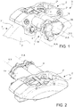
figure 1 shows a perspective view of an example of a brake caliper comprising a locking device of an electromagnetically-operated brake caliper according to the invention; -
figure 2 shows another perspective view of the brake caliper infigure 1 ; -
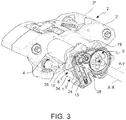
figure 3 shows the perspective view infigure 1 , in which an example of a locking device of an electromagnetically-operated brake caliper according to the invention is made visible by removing a closing cover; -
figure 4 shows an axonometric view of the locking device infigure 3 , in a parking braking position; -
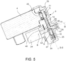
figure 5 shows a sectional view of the locking device infigure 4 , sectioned through a sectional plane V-V; -
figure 6 shows an axonometric view of the locking device infigure 3 , in a position without parking braking; -
figure 7 shows a sectional view of the locking device infigure 6 , sectioned through a sectional plane V-V; -
figure 8 shows a sectional view of one embodiment of a locking device according to the invention, sectioned through a sectional plane V-V, comprising a fastening device comprising a rolling body; -
figure 9 shows a sectional view of another embodiment of a locking device according to the invention, sectioned through a sectional plane V-V, in which the fastening device comprises an elastic retaining ring; -
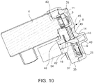
figure 10 shows a sectional view of a further embodiment of a locking device according to the invention, sectioned through a sectional plane V-V, comprising position sensors; -
figure 11 shows an axonometric view of the locking device for an electromagnetically-operated brake caliper according to the invention; -
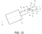
figure 12 shows a side view of a selector element associated with a linear actuator of a locking device according to the invention; -
figure 13 shows an axonometric view of the locking device according to the invention, according to an alternative embodiment in which the follower comprises an elastically deformable portion; -
figure 14 shows an embodiment of the locking device according to the invention, in which the selector element has an offset portion in engaged position and therefore with parking brake applied; -
figure 15 shows a sectional view of the locking device, alone, offigure 14 , in disengaged position and therefore with parking brake released. - With reference to the figures and according to a general embodiment, a locking device of an electromechanically-operated brake caliper for a disc brake according to the invention is generally indicated with
numeral 1. - The
locking device 1 comprises aratchet 8 comprising arotating element 11 having at least onefirst cam 12 and onefirst follower 13 pushed elastically against said rotatingelement 11, the first follower being configured to act in conjunction with saidfirst cam 12 to allow the rotation of therotating element 11 in a first direction of rotation A and to prevent the rotation of the rotating element in a second direction of rotation R, opposite to said first direction of rotation. - In accordance with one embodiment, said first direction of rotation A is a counterclockwise direction of rotation and said second direction of rotation R is a clockwise direction of rotation.
- In accordance with one embodiment, the rotating
element 11 is a wheel defining awheel rotation axis 22, for example stationary or integral with thecaliper body 2, and a wheelradial direction 23 orthogonal to thewheel rotation axis 22. - In accordance with one embodiment, the at least one
cam 12 extends in the radial direction. - According to one embodiment, the at least one
first cam 12 comprises a first cam profile segment 12' and a second cam profile segment 12'' adjacent to said first cam segment 12'. - According to one embodiment, the first cam profile segment 12' is arranged in the radial direction, or in a direction that promotes the engagement thereof with the
first follower 13 and the maintenance of such a position, for example the first cam profile segment is rectilinear. - In accordance with one embodiment, the second
cam profile segment 12" is inclined with respect to theradial direction 23, for example the second cam profile segment 12'' extends in a direction adapted to promote the sliding of the secondcam profile segment 12" with respect to thefirst follower 13, saidfirst follower 13 being pushed against said secondcam profile segment 12", for example said secondcam profile segment 12" is curved, for example said secondcam profile segment 12" is convex moving away from thewheel axis 22 in the radial direction. - In accordance with one embodiment, the second cam profile segment 12'' moves away from the wheel axis by angularly moving close to said first cam profile segment 12' on only one side of said first cam profile segment 12' .
- In accordance with one embodiment, the first cam profile segment 12' is facing in a direction of clockwise rotation of the
wheel 11. - In accordance with one embodiment, the at least one
first cam 12 is defined by a first cam surface and by a second cam surface adjacent to the first cam surface, in which such a first cam surface comprises said first cam profile segment 12', and for example such a second cam surface comprises said secondcam profile segment 12". - In accordance with one embodiment, the first cam surface and/or the second cam surface extend according to directions parallel to the
wheel axis 22. - In accordance with one embodiment, the rotating element 10 comprises a plurality of
cams 12 as described above, for example distributed along the periphery of saidwheel 11, for example equally spaced from one another at a pitch having a predetermined value. - In accordance with one embodiment, the plurality of cams comprises seven cams, for example substantially equal to one another.
- In accordance with one embodiment, the pitch value is chosen so as to ensure a safe and firm engagement of said rotating
element 11 against saidfirst follower 13 to prevent the rotation of the rotating element in a second direction of rotation R and at the same time to ensure a free rotation of the rotating element in the first direction of rotation A. - The
first follower 13 is restrained to thelocking device 1 to slide in a predetermined first follower sliding direction S-S with respect to the rotatingelement 11. - In accordance with one embodiment, the
first follower 13 comprises an elongate element which extends in said first follower sliding direction S-S and comprises afree end 17 facing therotating element 11. - In accordance with one embodiment, the
free end 17 of thefirst follower 13 is defined by a side surface 17' arranged laterally, or longitudinally, with respect to the first follower sliding direction S-S, and by ahead surface 17" arranged transversely with respect to the first follower sliding direction S-S. - In accordance with one embodiment, the side surface 17' is configured to receive in abutment the first cam profile segment 12' of a
first cam 12, and thehead surface 17" is adapted to receive in abutment the secondcam profile segment 12" of anotherfirst cam 12 arranged downstream of thefirst cam 12 in the second direction of rotation R. - In accordance with one embodiment, the first follower sliding direction S-S of the
first follower 13 belongs to a plane orthogonal to thewheel axis 22 and is arranged in the tangential direction with respect to thewheel axis 22, or is orthogonal to aradial direction 23. - In accordance with one embodiment, said first follower is restrained to the locking device to rotate or roto-translate about a point of the
locking device 1, and said first follower sliding direction S-S belongs to a plane orthogonal to thewheel axis 22 and consists of a line corresponding to the trajectory travelled by saidfirst follower 13 during said rotation or roto-translation. - In accordance with one embodiment, the side surface 17' and the
head surface 17" extend orthogonally to a plane orthogonal to thewheel axis 22. - In accordance with one embodiment, the side surface 17' and the
head surface 17" are substantially orthogonal to each other. - In accordance with one embodiment, the side surface 17' and the
head surface 17" are substantially orthogonal to each other, and they are inclined by a predetermined angle with respect to the first follower sliding direction S-S. - Thereby, when the first cam profile segment 12' abuts against the side surface 17', such a first cam profile segment 12' applies to the side surface 17' a thrust component which pulls the
first follower 13 againstwheel 11. In this circumstance, thehead surface 17" abuts against the second cam profile segment of anadjacent cam 12, which applies to thehead surface 17" a thrust component which opposes the thrust component that pulls the first follower against the wheel. Thereby, self-locking is obtained in these circumstances, which ensures the parking braking load is maintained over time. - In accordance with one embodiment, the side surface 17' extends in a direction parallel to the wheel
radial direction 23, or in such a direction as to promote the engagement thereof with thefirst follower 13. For example, thehead surface 17" extends in a direction orthogonal to the wheelradial direction 23, or tangentially towheel 11. - In accordance with one embodiment, the side surface 17' extends along a plane parallel to a radial plane passing through the
wheel axis 23, or along a plane which allows the engagement thereof with thefirst follower 13. - In accordance with one embodiment, the
head surface 17" extends along a plane substantially orthogonal to a radial plane passing through thewheel axis 23. - In accordance with one embodiment, as for example shown in
figure 11 , thefirst follower 13 comprises two oppositelateral sliding surfaces 18 parallel to each other and parallel to the first follower sliding direction S-S, slidingly engaged withcounter sliding surfaces 24 which are integral with said lockingdevice 1. - In accordance with one embodiment, as shown for example in
figure 13 , thecounter sliding surfaces 24 of the locking device are surfaces parallel to each other and having a curved portion approaching therotating element 11, and at least one portion of thefirst follower 13 facing towards the rotating element is elastic so that thefirst follower 13 is elastically deformed along the curved counter surfaces 24 accumulating elastic energy upon sliding from the disengaged position to the engaged position, and so that saidfirst follower 13 releases the elastic energy accumulated upon sliding from the engaged position to the disengaged position. This solution allows athrust spring 25 for pushing thefirst follower 13 against the rotatingelement 11 to be avoided. - In accordance with one embodiment, ratchet 8 comprises elastic thrust means 25 which act against the
first follower 13 in the first follower sliding direction S-S. For example, the thrust means comprise a compression spring. - The
locking device 1 comprises aselector element 15 sliding between a first selector element position and a second selector element position, saidselector element 15 being adapted to operate saidfirst follower 13 so that, in said first selector element position, saidselector element 15 keeps saidfirst follower 13 in a disengaged position away from the rotatingelement 11 to prevent the application of a parking braking action, and so that, in said second selector element position, theselector element 15 keeps saidfirst follower 13 in an engaged position in contact with saidrotating element 11 to allow the application of a parking braking action. - The
selector element 15 comprises asecond cam 16 and thefirst follower 13 has a first follower opening 14 forming asecond follower 9, saidsecond cam 16 being configured to act in conjunction with saidsecond follower 9 to operate saidfirst follower 13 between said engaged position and said disengaged position. - The
selector element 15 comprises apin portion 29 which extends in a selector element sliding direction B-B and the first follower opening 14 is an opening passing through thefirst follower 13 configured to allow the sliding therein of thepin portion 29 in said selector element sliding direction B-B. - The first follower opening 14 is defined by an opening
edge 26, e.g. a closed opening edge. - Such an opening
edge 26 comprises two straight opposite openingedge portions 27 parallel to each other and to the first follower sliding direction S-S. - In accordance with one embodiment, the
closed opening edge 26 comprises a portion of thebottom opening edge 32 which connects one end of the oppositeopening edge portions 27 furthest away from the free end offirst follower 17 to each other. - In accordance with one embodiment, the portion of the
bottom opening edge 32 forms saidsecond follower 9. - In accordance with one embodiment, the portion of the
bottom opening edge 32 is substantially straight and orthogonal to said opposite openingedge portions 27. In other words, the portion of the bottomabutment opening edge 32 is substantially straight and orthogonal to the first follower sliding direction S-S. - In accordance with one embodiment, the
pin portion 29 comprises two side flattenings 28 parallel to each other. Such side flattenings 28 are adapted to act in conjunction with the straightopening edge portions 27 to guide thepin portion 29 during the sliding through the first follower opening 14, thus avoiding the rotation of thepin portion 29 with respect to the first follower opening 14. Moreover, such side flattenings 28 are adapted to also guide the sliding of thefirst follower 13 transversely to thepin portion 29 at thesecond cam 16. - In accordance with one embodiment, said selector element sliding direction B-B is substantially orthogonal to the first follower sliding direction S-S.
- In accordance with one embodiment, said selector element sliding direction B-B is substantially parallel to the direction of the
wheel rotation axis 22. - In accordance with one embodiment, the
pin portion 29 comprises a notch which laterally penetrates said pin portion, said notch forming saidsecond cam 16. - In accordance with one embodiment, said notch is defined by a cam surface which extends in a direction orthogonal to the selector element sliding direction B-B.
- Said
second cam 16 comprises asupport segment 31 adapted to come in abutment with said portion of thebottom opening edge 32 of said follower opening 14 in said disengaged position. The elastic means 25 contribute to bringing the portion of thebottom opening edge 32 in abutment against such asupport segment 31. - In accordance with one embodiment, the
second cam 16 comprises abottom segment 30 which penetrates thepin portion 29 transversely to the selector element sliding direction B-B and in the first follower sliding direction S-S and towards said free end offirst follower 17, to leave a space in thepin element 29 to allow thefirst follower 13 to reach the engaged position. - In accordance with one embodiment, said
second cam 16 comprises aninclined segment 33 which connects one end of saidsupport segment 31 with one end of saidbottom segment 30 to allow a gradual transition of saidfirst follower 13 from said disengaged position to said engaged position, and vice versa. - The thickness s of the
pin element 29 as measured in the first follower sliding direction S-S at saidbottom segment 30 is less than the thickness of thepin element 29 as measured in the first follower sliding direction S-S at saidsupport segment 31. - In accordance with one embodiment, as shown for example in
figures 14 and15 , theselector element 15 comprises an offset end portion 15' forming saidsecond cam 16, comprising saidinclined segment 33. - In accordance with one embodiment, the
locking device 1 comprises alinear actuator 34 adapted to move said selector element between said first selector element position and said second selector element position. - In accordance with one embodiment, the
linear actuator 34 is an electromagnetic actuator, for example a solenoid actuator, or an electric motor for imparting the required linear movement. In accordance with one embodiment, the electric motor is a linear motor which directly connects to said selector element to move it between said first selector element position and said second selector element position, and vice versa. In accordance with a further embodiment, said electric motor is of the rotary type keyed downstream of a nut screw of a screw-nut screw system capable of moving, with a desired irreversible drive ratio, said selector element between said first selector element position and said second selector element position, and vice versa. - In accordance with one embodiment, the
linear actuator 34 is configured to change the position of theselector element 15 between the first position and the second position, and vice versa, only if electrically powered, and is configured to keep theselector element 15 in the first position or in the second position when it is not electrically powered. - In accordance with one embodiment, the electromagnetic
linear actuator 34 is of the bistable type, for example a bistable solenoid actuator, which comprises a first electrical winding adapted to move theselector element 15 from the first position to the second position when the first electrical winding is electrically powered, and a second electrical winding opposite to the first electrical winding adapted to move theselector element 15 from the second position to the first position when the second electrical winding is electrically powered. In accordance with one embodiment, the electromagneticlinear actuator 34 is of the bistable type, for example a bistable solenoid actuator, which comprises a single winding adapted to move theselector element 15 from the first position to the second position when powered with "positive" current, and adapted to move theselector element 15 from the second position to the first position when powered with "negative" current or of direction/phase opposite to the preceding one. - Although this solution requires controlling the two windings separately, or driving currents with opposite directions/phases, it advantageously allows a mechanical engagement device to be avoided, thus simplifying the construction of the device.
- In accordance with one embodiment, the
locking device 1 comprises means for retaining said selector element to keep said selector element in said first and second position when the first and second windings are not electrically powered, for example said retaining means comprise magnets or snap mechanical blocks. - In accordance with one embodiment, the
electromagnetic actuator 34 is of the monostable type and comprises an electrical winding adapted to move theselector element 15 from the first position to the second position when the winding is electrically powered, and comprises return means to bring theselector element 15 back from the second position to the first position when the winding is not powered; and thelocking device 1 comprises a mechanical engagement device adapted to keep theselector element 15 in said second position of saidelectromagnetic actuator 34 following a first electricity supply of the electrical winding, and to allow the return of theselector element 15 in the first position following a second and successive electricity supply. - Although it requires a mechanical engagement device, this solution advantageously allows a simpler electrical connection and a simpler control of the device because only one electrical winding requires to be electrically powered. In accordance with one embodiment, the
locking device 1 comprises a selectorelement engagement device 48 adapted to engage the selector element in said first selector element position and/or in said second selector element position, for example said selectorelement engagement device 48 is a snap engagement device. - In accordance with one embodiment, the selector
element engagement device 48 comprises anengagement body 49 adapted to be pushed against anouter side surface 50 of saidselector element 15, or against an outer surface of saidpin portion 29 of selector element, in which saidouter side surface 50 of saidselector element 15, or said outer surface of saidpin portion 29 of selector element, comprises afirst notch 47 adapted to receive a portion of saidengagement body 49 when saidselector element 15 is in said first position to keep theselector element 15 in said first position, and/or comprises asecond notch 46 adapted to receive a portion of saidengagement body 49 when saidselector element 15 is in said second position to keep theselector element 15 in said second position. - In accordance with one embodiment, the selector
element engagement device 48 comprises elastic thrust means adapted to push said engagement body in a direction transversal to the selector element sliding direction B-B. - In accordance with one embodiment, said engagement body is an elastic gasket (
figure 9 ). - In accordance with one embodiment, the
locking device 1 comprises asupport plate 36, orsupport tray 36, adapted to be attached to thecaliper body 2 and defining anouter face 37 and an oppositeinner face 38. - In accordance with one embodiment, said
support plate 36 is adapted to slidingly support saidselector element 15 through a first through-opening of thesupport plate 42. - In accordance with one embodiment, said
linear actuator 36 is attached to saidsupport plate 36, for example saidactuator 36 is attached to theouter face 37. - In accordance with one embodiment, as for example shown in
figures 4 ,6 and11 , saidcounter sliding surfaces 24 are made in saidsupport plate 36, for example in saidinner face 38. - In accordance with one embodiment, said
drive shaft 5 is slidingly supported by saidsupport plate 36 through a second through-opening of thesupport plate 43. - In accordance with one embodiment, the
electric motor 4 is attached to saidsupport plate 36, for example is attached to theouter face 37. - In accordance with one embodiment, for example as shown in
figures 1 ,5 ,7 to 10 , the locking device comprises acover 39 adapted to be attached to saidsupport plate 36 facing saidinner face 38, so as to form a closed compartment between saidsupport plate 36 and saidcover 39 for containing saidratchet 8 in said closed compartment. - In accordance with one embodiment, the locking device comprises a
guide surface 40 adapted to slidingly guide afree end portion 41 of saidselector element 15 or of saidpin portion 29 of selector element. - In accordance with one embodiment, said
guide surface 40 is made in saidcover 39 and is aligned with said first opening ofsupport plate 42. - In accordance with one embodiment, said
guide surface 40 is the surface of a hole, e.g. a blind hole. - In accordance with one embodiment (
figure 8 ), thesecond follower 9 comprises a rollingbody 35 interposed between saidopening 14 and saidsecond cam 16, in contact with saidsecond cam 16. Thereby, a reduction is obtained of the friction between thesecond follower 9 and theselector element 15. - In accordance with one embodiment (
figure 9 ), theguide surface 40 houses agasket 44, or anelastic ring 44, for example metallic, which is operatively interposed between said guide surface and said free end ofselector element 41 to facilitate the sliding of the free end ofselector element 41 in saidguide surface 40. - In accordance with one embodiment, the
locking device 1 comprises at least one selector element position sensor adapted to detect the position of theselector element 15 in the selector element sliding direction B-B, or with respect to thesupport plate 36. - In accordance with one embodiment, the at least one selector element position sensor is integrated in the
linear actuator 34. - In accordance with one embodiment (
figure 10 ), thelocking device 1 comprises at least one firstfollower position sensor 45 adapted to detect the position of saidfirst follower 13 in the first follower sliding direction S-S. - In accordance with one embodiment, the at least one first
follower position sensor 45 is integrated in thefirst follower 13. - In accordance with one embodiment, the at least one first
follower position sensor 45 comprises an active portion adapted to be electrically powered, which is integral with one of saidfirst follower 13 and saidcover 39 or saidsupport plate 36, and a passive portion which does not require to be electrically powered and is adapted to act in conjunction with the active portion, which is integral with the other of saidfirst follower 13 and saidcover 39 or saidsupport plate 36. For example, the active portion is integral with said cover or said support plate, and the passive portion is integral with thefirst follower 13. - In accordance with one embodiment, the
locking device 1 is made as a separate unit from the brake caliper 3 adapted to be mounted on a brake caliper 3. - According to another aspect of the present invention, the aforesaid objects and advantages are met by an electromechanically-operated brake caliper 3 for a disc brake, comprising a
caliper body 2 suitable for being arranged astride abrake disc 7 having a first braking surface 7' and asecond braking surface 7". - The
caliper body 2 comprises a first vehicle side portion 2' suitable for facing said first braking surface 7' of the brake disc, said first vehicle side portion 2' comprising thrust means 19 housed therein to allow said at least one brake pad to move close to/away from saiddisc 7. - The first portion 2' comprises at least one first seat suitable for receiving at least one first pad suitable for facing and being arranged substantially parallel to said first braking surface 7'.
- The at least one first pad being housed in said at least one first seat in a sliding manner and so as to be arranged between said first vehicle side portion 2' and said first braking surface 7' and to exert a braking action on the
brake disc 7 when affected by said thrust means 19. - The brake caliper 3 comprises a rotary
electric motor 4 having adrive shaft 5. - The thrust means 19 are adapted to receive a rotary motion and a torque from said rotary
electric motor 4 and to convert said rotary motion into translation motion to affect said at least one pad. - Caliper 3 comprises a
gearbox 6 operatively connected with an input side thereof to saiddrive shaft 5 to receive a movement and a driving torque and transmit them with an output side thereof to said thrust means 19. - The caliper comprises a
locking device 1 as described above, in which saidrotating element 11 of saidratchet 8 is connected to receive a rotation motion from saiddrive shaft 5. - According to another aspect of the present invention, the aforesaid objects and advantages are met by an electromechanically-operated parking brake caliper 3 for a disc brake, comprising a
caliper body 2 suitable for being arranged astride abrake disc 7 having a first braking surface 7' and asecond braking surface 7". - The
caliper body 2 comprises a first vehicle side portion 2' suitable for facing said first braking surface 7' of the brake disc, said first vehicle side portion 2' comprising thrust means 19 housed therein to allow said at least one brake pad to move close to/away from saiddisc 7. - The first portion 2' comprises at least one first seat suitable for receiving at least one first pad suitable for facing and being arranged substantially parallel to said first braking surface 7'.
- The at least one first pad being housed in said at least one first seat in a sliding manner and so as to be arranged between said first vehicle side portion 2' and said first braking surface 7' and to exert a braking action on the
brake disc 7 when affected by said thrust means 19. - The brake caliper 3 comprises a rotary
electric motor 4 having adrive shaft 5. - The thrust means 19 are adapted to receive a rotary motion and a torque from said rotary
electric motor 4 and to convert said rotary motion into translation motion to affect said at least one pad. - Caliper 3 comprises a
gearbox 6 operatively connected with an input side thereof to saiddrive shaft 5 to receive a movement and a driving torque and transmit them with an output side thereof to said thrust means 19. - The caliper comprises a
locking device 1 as described above, in which saidrotating element 11 of saidratchet 8 is connected to receive a rotation motion from saiddrive shaft 5. - In accordance with one embodiment, the rotating element is attached or can be attached coaxially to the
drive shaft 5 of a rotaryelectric motor 4 adapted to provide a rotary motion and a torque to thrust means 19 configured to move at least one brake pad close to/away from abrake disc 7. - In accordance with one embodiment, the rotating
element 11 is mounted on thedrive shaft 5 so as to prevent any related rotation between rotatingelement 11 and driveshaft 5, for example by means of a shape coupling. - In accordance with one embodiment, the rotating
element 11 is axially restrained to thedrive shaft 5 by means of a Seeger® ring. - According to another aspect of the present invention, these and other objects and advantages are met by a method for operating an electromechanically-operated brake caliper 3 as described above, to operate a parking braking, comprising the steps of:
- - operating the
electric motor 4 to rotate thedrive shaft 5 in a first braking direction of rotation to push said at least one pad against said first braking surface 7' up to reaching a thrust force value suitable for operating a parking braking, saiddrive shaft 5 simultaneously rotating saidrotating element 11 in said first direction of rotation; - - translating said
selector element 15 from said first position to said second position to keep saidfirst follower 13 in an engaged position in contact with saidrotating element 11 to allow the application of a parking braking action; - - rotating said
rotating element 11 in said second direction of rotation up to bringing thefirst cam 12 in abutment against saidfirst follower 13; - - stopping the operation of the
electric motor 4. - In accordance with one embodiment, the step of rotating said
rotating element 11 in said second direction of rotation R up to bringing thefirst cam 12 in engaging abutment against saidfirst follower 13 is executed by operating theelectric motor 4 in a direction of rotation adapted to rotate saidrotating element 11 in the second direction of rotation R;
or by stopping the operation of theelectric motor 4 and allowing the reaction force of the pads to rotate therotating element 11 in the second direction of rotation R;
or by keeping theelectric motor 4 operating in a direction of rotation adapted to affect therotating element 11 in the first direction of rotation A to dampen the rotation of therotating element 11 in the second direction of rotation R due to the reaction force of the pads. In accordance with one embodiment (fig. 15 ), thelinear actuator 34 can be controlled so as to impose three different positions on theselector element 15. Two positions of theselector element 15 correspond to the ones described above infigure 5 andfigure 7 . The third position, depicted infigure 15 , allows thefirst follower 13 to be forced in engaged position with therotating element 11 if, during a reapplication of the braking force on the parked vehicle (rotation of therotating element 11 in the first direction of rotation, with the force exchanged between pads and disc increasing), thethrust spring 25 has a breakdown for which the engagement of thefirst follower 13 with therotating element 11 may no longer be ensured. Due to this solution, the loss of the braking load is avoided in case of breakdown of thethrust spring 25 during the step of automatic reapplication of the braking force in the absence of the driver. - According to another aspect of the present invention, these and other objects and advantages are met by a method for operating an electromechanically-operated brake caliper 3 as described above, to remove a parking braking, comprising the steps of:
- rotating the
rotating element 11 in the first direction of rotation up to disconnecting said rotating element (11) from saidfirst follower 13, for example by operating theelectric motor 4; - translating said
selector element 15 from said second position to said first position to keep saidfirst follower 13 away from saidfirst cam 12; - operating the
electric motor 4 to rotate thedrive shaft 5 in a second braking direction of rotation to move said at least one pad away from said first braking surface 7' up to removing the parking braking, saiddrive shaft 5 simultaneously rotating saidrotating element 11 in said second direction of rotation. - The locking device of an electromechanically-operated brake caliper 3 for a disc brake described above in terms of its technical features will now be described in terms of the operation thereof.
- The application of the parking braking, or insertion of the parking brake, occurs by first operating the
electric motor 4 up to reaching the parking load required. - The rotating element comprising the first cams is integral with the
drive shaft 5, therefore rotates at the same time as the rotation of the motor. With reference to the accompanying drawings, the drive shaft and the rotating element are rotated in counterclockwise direction. - Once the predetermined parking load value is reached, the
selector element 15 is actuated in translation from the first position to the second position, for example by operating thelinear actuator 34. - During the translation of the
selector element 15, the cooperation between thesecond cam 16 of theselector element 15 and thesecond follower 9 brings the first follower in engaged position. - Once this step is complete, the
electric motor 4 is operated in an opposite direction of rotation, in clockwise direction with reference to the figures, up to bringing a first cam in abutment against a side of the free end of first follower. - Thereby, the parking braking condition is achieved and maintained. Under such a condition, the reaction force to the parking involves the thrust means 19 for moving the pads close to/away from the braking surfaces of the disc,
gearbox 6 interposed between thedrive shaft 5 and the thrust means 19, thedrive shaft 5, the rotatingelement 11, thefirst follower 13, thesupport plate 36, and does not involve, instead, the other components. - After the application of the parking braking, and therefore with the vehicle stopped, the brake components may cool down, with subsequent reduction of the sizes. In these circumstances, but also in others, the compression force of the pads against the braking surfaces may decrease, thereby decreasing the load applied.
- The locking device of the present invention may be used to restore the braking load required to ensure the parking braking action is maintained, for example in the following manner.
- Once the parking braking is applied, therefore in the engaged position of the
first follower 13, theelectric motor 4 is operated in the direction of rotation of load application, in counterclockwise direction with reference to the figures, up to reaching the predetermined braking load required to reach and maintain the parking braking action again. - The release of the parking braking, or disengagement of the parking brake, occurs by operating the
electric motor 4, in counterclockwise direction with reference to the figures, up to disconnecting the first segment of first cam 12' from the side surface 17' of thefirst follower 13. - The
selector element 15 is then operated to slide from the second position to the first position, for example by operating the linear actuator. - During the translation of the
selector element 15, the cooperation between thesecond cam 16 of theselector element 15 and thesecond follower 9 brings the first follower in disengaged position. - With reference to the accompanying drawings, once this step is complete, the
drive shaft 5 and therotating element 11 are rotated in counterclockwise direction up to moving the pads away from the braking surfaces of the brake disc. - Advantageously, the locking device described above requires operating the actuator only in the transition between the engaged condition and the disengaged position, and avoids requiring a continuous power supply of the actuator during the entire disengaged step or during the entire engaged step.
- This results in significant advantages, including very safe use because no interruption in the electricity supply of the actuator, or a breakdown, or a malfunction, ever causes an undesired change in status between the engaged position and the disengaged position, or vice versa. Indeed, in case of an interruption in power supply or breakdown, such a locking device remains in the existing status when such a condition occurs. This allows a highly reliable locking device to be provided.
- Advantageously, the locking device does not require to be continuously powered to keep the disengaged position, that is with parking brake disengaged.
- Equally advantageously, the locking device does not require to be continuously powered to keep the engaged position, that is with parking brake engaged.
- Moreover, the parking locking device advantageously requires to be electrically powered only when changing the position between engaged position and disengaged position.
- In other words, the locking device according to the invention not only ensures safety of use by preventing the involuntary operation or disabling of the parking brake, but also allows less onerous electromechanical dimensioning.
- Advantageously, in order to operate the selector element, the actuator is not directly stressed by the parking force, with subsequent smaller stresses. This allows a compact-sized actuator to be used and allows materials to be used which do not necessarily have significant mechanical features. Accordingly, the cost of the device is thereby reduced.
- Advantageously, if the motor should not ensure the coverage of the angular sector between the two first adjacent cams, no involuntary change of status would occur along such a sector between the engaged position and the disengaged position, and vice versa. In other words, the status of application or non-application of the parking brake at the preceding cam, would be maintained.
- In other words, no involuntary loss of parking braking load would occur in such a case.
- Another important advantage produced by the present invention is given by the fact that, if the spring adapted to push the first follower against the rotating element breaks, it would not cause any involuntary insertion of the parking brake.
- Advantageously, moreover, when there is a loss of parking braking load due to the variation in volume of the braking components following temperature variations, for example following the cooling of the brake when the vehicle is stopped, the locking device according to the invention advantageously allows the parking load lost to be reapplied by acting only on the motor and not on the actuator of the selector element.
- Such a locking device, therefore, does not require acting on the selector element to restore the parking braking load, but only on the motor used to move and push the pads against the braking surfaces of the brake disc. This contributes to reducing the use of the actuator of the selector element, and therefore to increasing the reliability and safety of use.
- A person skilled in the art may make several changes and adaptations to the above-described embodiments of the device, and substitute elements with other functionally-equivalent ones, in order to meet contingent needs, without thereby departing from the scope of the following claims.
- Each of the features described as belonging to a possible embodiment may be achieved irrespective of the other embodiments described. Various means and materials may be used to perform the different functions described without thereby departing from the scope of the invention. It should be understood that the expressions and terminology used serve a merely descriptive purpose and are therefore non-limiting.
-
- 1
- locking device
- 2
- caliper body
- 2'
- first portion
- 3
- brake caliper
- 4
- electric motor
- 5
- drive shaft
- 6
- gearbox
- 7
- brake disc
- 7'
- first braking surface
- 7"
- second braking surface
- 8
- ratchet
- 9
- second follower
- 11
- rotating element
- 12
- first radial cam
- 12"
- first cam segment
- 12'
- second cam segment
- 13
- first follower
- 14
- first follower opening
- 15
- selector element
- 16
- second cam
- 17
- free end of first follower
- 17'
- side surface
- 17"
- head surface
- 18
- sliding surfaces
- 19
- thrust means
- 22
- wheel axis
- 23
- wheel radial direction
- 24
- sliding counter surfaces
- 25
- Seeger ring
- 26
- opening edge
- 27
- straight opening edge segments
- 28
- side flattenings
- 29
- pin portion
- 30
- bottom segment
- 31
- support segment
- 32
- portion of the bottom abutment opening edge
- 33
- inclined segment
- 34
- linear actuator
- 35
- rolling body
- 36
- support plate
- 37
- outer face of support plate
- 38
- inner face of support plate
- 40
- guide surface
- 41
- free end of selector element
- 42
- first through-opening of the support plate
- 43
- second through-opening of the support plate
- 44
- gasket
- 45
- first follower position sensor
- 46
- second notch
- 47
- first notch
- 48
- selector element engagement device
- 49
- engagement body
- A
- first direction of rotation
- R
- second direction of rotation
Claims (10)
- A locking device (1) of an electromechanically-operated brake caliper (3) for a disc brake, comprising:- a ratchet (8) comprising a rotating element (11) having at least one first cam (12) and one first follower (13) pushed elastically against said rotating element, configured to act in conjunction with said at least one first cam (12) to allow the rotation of the rotating element (11) in a first direction of rotation (A) and to prevent the rotation of the rotating element in a second direction of rotation (R) opposite to said first direction of rotation;
characterized in that- a selector element (15) sliding between a first selector element position and a second selector element position, said selector element (15) being adapted to operate said first follower (13) so that, in said first selector element position, said selector element (15) keeps said first follower (13) in a disengaged position away from the rotating element (11) to prevent the application of a parking braking action, and so that, in said second selector element position, the selector element (15) keeps said first follower (13) in an engaged position in contact with said rotating element (11) to allow the application of a parking braking action,- said selector element having a second cam (16) and said first follower (13) having a first follower opening (14) forming a second follower (9), said second cam (16) being configured to act in conjunction with said second follower (9) to operate said first follower between said engaged position and said disengaged position. - A locking device according to claim 1, wherein the at least one first cam (12) comprises a first cam profile segment (12') and a second cam profile segment (12") adjacent to said first cam segment (12'), and wherein the first cam profile segment (12') is arranged in the radial direction, or wherein the at least one first cam (12) comprises a first cam profile segment (12') and a second cam profile segment (12") adjacent to said first cam segment (12'), and the first cam profile segment (12') is arranged in a direction that promotes engagement with the first follower (13) and the maintenance of such a position, or wherein the at least one first cam (12) comprises a first cam profile segment (12') and a second cam profile segment (12") adjacent to said first cam segment (12'), and the second cam profile segment (12") is inclined with respect to the radial direction (23), or wherein the at least one first cam (12) comprises a first cam profile segment (12') and a second cam profile segment (12") adjacent to said first cam segment (12'), and the second cam profile segment (12") extends in a direction adapted to promote the sliding of the second cam profile segment (12") with respect to the first follower (13), or wherein the at least one first cam (12) comprises a first cam profile segment (12') and a second cam profile segment (12") adjacent to said first cam segment (12'), and the second cam profile segment (12") moves away from the wheel axis proceeding angularly towards said first cam profile segment (12') on only one side of said first cam profile segment (12').
- A locking device according to claim 2, wherein the rotating element (10) comprises a plurality of cams (12) distributed along the periphery of said wheel (11) and equally spaced from one another at a pitch having a predetermined value, wherein said predetermined pitch value is chosen so as to ensure a safe and firm engagement of said rotating element (11) against said first follower (13) to prevent the rotation of the rotating element (11) in a second direction of rotation (R) and at the same time to ensure a free rotation of the rotating element in the first direction of rotation (A).
- A locking device according to at least one of the previous claims, wherein the first follower (13) is restrained to the locking device (1) to slide in a predetermined first follower sliding direction (S-S) with respect to the rotating element (11), and wherein the first follower (13) comprises an elongated element which extends along said first follower sliding direction (S-S) and comprises a free end (17) facing the rotating element (11), and wherein the free end (17) of the first follower (13) is defined by a side surface (17') arranged laterally, or longitudinally, with respect to the first follower sliding direction (S-S), and by a head surface (17") arranged transversely to the first follower sliding direction (S-S), and wherein the side surface (17') is configured to receive in abutment the first cam profile segment (12') of a first cam (12), and the head surface (17") is adapted to receive in abutment the second cam profile segment (12") of another first cam (12) arranged downstream of the first cam (12) in the second direction of rotation (R).
- A locking device according to at least one of the previous claims, wherein the selector element (15) comprises a pin portion (29) which extends in a selector element sliding direction (B-B) and the first follower opening (14) is an opening passing through the first follower (13) configured to allow the sliding of the pin portion (29) inside it in said selector element sliding direction (B-B).
- A locking device according to at least one of the previous claims, comprising a linear actuator (34) adapted to move said selector element (15) between said first selector element position and said second selector element position, or wherein a linear actuator (34) is adapted to move said selector element (15) between said first selector element position and said second selector element position, and the linear actuator (34) is an electromagnetic actuator, for example a solenoid actuator and/or a linear and/or rotary electric motor keyed to a screw-nut screw system and/or wherein the linear actuator (34) is configured to change the position of the selector element (15) from the first position to the second position and vice versa only when electrically powered, and is configured to keep the selector element (15) in the first position or second position when it is not electrically powered.
- An electromechanically-operated brake caliper (3) for a disc brake, comprising:- a caliper body (2) suitable for being arranged astride a brake disc (7) having a first braking surface (7') and a second braking surface (7");- said caliper body (2) comprising a first vehicle side portion (2') suitable for facing said first braking surface (7') of the brake disc;- said first vehicle side portion (2') comprising thrust means (19) housed therein to allow said at least one brake pad to move close to/away from said disc (7);- said first portion (2') comprising at least one first seat suitable for receiving at least one first pad suitable for facing and being arranged substantially parallel to said first braking surface (7');- said at least one first pad being housed in said at least one first seat in a sliding manner and so as to be arranged between said first vehicle side portion (2') and said first braking surface (7') and to exert a braking action on the brake disc (7) when affected by said thrust means (19);- a rotary electric motor (4) having a drive shaft (5);- said thrust means (19) being adapted to receive a rotary motion and a torque from said rotary electric motor (4) and to convert said rotary motion into translation motion to affect said at least one pad;- a gearbox (6) operatively connected with an input side thereof to said drive shaft (5) to receive a movement and a driving torque and transmit them with an output side thereof to said thrust means (19);- a locking device (1) according to at least one of the preceding claims, wherein said rotating element (11) of said ratchet (8) is connected to receive a rotation motion from said drive shaft (5).
- An electromechanically-operated brake caliper (3) according to claim 7, wherein said electromechanically-operated brake caliper (3) is a parking brake caliper.
- A method for operating an electromechanically-operated brake caliper (3) according to claim 7 or 8, to operate a parking braking, comprising the steps of:- operating the electric motor (4) in a direction of rotation adapted to push said at least one pad against said first braking surface (7') up to reaching a thrust force value suitable for operating a parking braking, said drive shaft (5) simultaneously rotating said rotating element (11) in a first direction of rotation (A) ;- translating said selector element (15) from said first position to said second position to keep said first follower (13) in an engaged position in contact with said rotating element (11) to allow the application of a parking braking action;- rotating said rotating element (11) in a second direction of rotation (R) opposite to the first direction of rotation (A) up to bringing the first cam (12) in abutment against said first follower (13);- stopping the operation of the electric motor (4).
- A method for operating an electromechanically-operated brake caliper (3) according to claim 7 or 8, to remove a parking braking, comprising the steps of:- operating the electric motor (4) to rotate the rotating element (11) in the first direction of rotation (A) up to disconnecting said rotating element (11) from said first follower (13);- translating said selector element (15) from said second position to said first position to keep said first follower (13) in the disengaged position away from said first cam (12);- operating the electric motor (4) in a direction of rotation adapted to move said at least one pad away from said first braking surface (7') up to removing the parking braking, said drive shaft (5) simultaneously rotating said rotating element (11) in said second direction of rotation (R).
Applications Claiming Priority (2)
| Application Number | Priority Date | Filing Date | Title |
|---|---|---|---|
| ITBG20150024 | 2015-04-27 | ||
| PCT/IB2016/052383 WO2016174587A1 (en) | 2015-04-27 | 2016-04-27 | Locking device of an electromagnetically-operated brake caliper, brake caliper comprising said caliper, method for operating said caliper |
Publications (2)
| Publication Number | Publication Date |
|---|---|
| EP3289239A1 EP3289239A1 (en) | 2018-03-07 |
| EP3289239B1 true EP3289239B1 (en) | 2020-06-17 |
Family
ID=53719807
Family Applications (1)
| Application Number | Title | Priority Date | Filing Date |
|---|---|---|---|
| EP16726175.9A Active EP3289239B1 (en) | 2015-04-27 | 2016-04-27 | Locking device of an electromagnetically-operated brake caliper, brake caliper comprising said caliper, method for operating said caliper |
Country Status (5)
| Country | Link |
|---|---|
| US (1) | US10458498B2 (en) |
| EP (1) | EP3289239B1 (en) |
| JP (1) | JP6816020B2 (en) |
| CN (1) | CN107810343B (en) |
| WO (1) | WO2016174587A1 (en) |
Families Citing this family (16)
| Publication number | Priority date | Publication date | Assignee | Title |
|---|---|---|---|---|
| KR101776496B1 (en) * | 2016-05-09 | 2017-09-19 | 현대자동차주식회사 | Electro-mechanical brake capable of detecting change in motor charateristic |
| CN112639324B (en) * | 2018-06-21 | 2022-11-11 | 乐姆宝公开有限公司 | Parking device for a brake caliper of a vehicle disc brake |
| US11377083B2 (en) * | 2018-11-15 | 2022-07-05 | Mando Corporation | Electromechanical actuator package for actuating brake assembly |
| EP3663149B1 (en) * | 2018-12-06 | 2023-03-29 | IMS Gear SE & Co. KGaA | Locking device for an electromechanical brake of motor vehicle brake, electromechanical brake provided with such a locking device and motor vehicle equipped with such an electromechanical brake |
| US12228185B2 (en) * | 2019-04-22 | 2025-02-18 | Hitachi Astemo, Ltd. | Disk brake |
| KR102644871B1 (en) | 2019-07-16 | 2024-03-07 | 현대모비스 주식회사 | Parking brake apparatus for vehicle |
| WO2021110651A1 (en) | 2019-12-05 | 2021-06-10 | Zf Cv Systems Europe Bv | Brake actuator, in particular electromechanical brake actuator of a commercial vehicle |
| KR20230019864A (en) | 2020-06-02 | 2023-02-09 | 리낙 에이/에스 | Locking of rotation of an electric motor of a linear actuator |
| KR102404524B1 (en) | 2020-08-25 | 2022-06-02 | 현대모비스 주식회사 | Parking brake apparatus for vehicle |
| EP4071007B1 (en) * | 2021-04-09 | 2023-06-14 | IMS Gear SE & Co. KGaA | Blocking device, brake gear with such a blocking device and service and/or parking brake |
| US12145551B2 (en) * | 2021-11-17 | 2024-11-19 | Zf Active Safety Gmbh | Actuator assembly for a vehicle brake and method for activating an actuator assembly for a vehicle brake |
| US12234873B2 (en) * | 2022-01-19 | 2025-02-25 | Hl Mando Corporation | Electromechanical parking brake system having parking brake locking mechanism |
| DE102022103978A1 (en) * | 2022-02-21 | 2023-08-24 | Zf Active Safety Gmbh | Electromotive actuator assembly for an electromechanical vehicle brake and method for activating and deactivating a parking brake function |
| JP2024021261A (en) * | 2022-08-03 | 2024-02-16 | 株式会社アドヴィックス | electric braking device |
| FR3162492A1 (en) | 2024-05-21 | 2025-11-28 | Sonceboz Motion Boncourt Sa | Mechatronic braking system |
| FR3165294A1 (en) * | 2024-08-02 | 2026-02-06 | Hitachi Astemo France | Brake lock and brake equipped with such a lock |
Family Cites Families (18)
| Publication number | Priority date | Publication date | Assignee | Title |
|---|---|---|---|---|
| US6315092B1 (en) | 1997-11-21 | 2001-11-13 | Continental Teves Ag & Co., Ohg | Electromechanically actuated disc brake |
| US6125983A (en) * | 1997-12-01 | 2000-10-03 | Chrysler Corporation | Electric parking sprag |
| DE19833304A1 (en) * | 1998-07-24 | 2000-02-10 | Daimler Chrysler Ag | Brake actuation device |
| DE19945543A1 (en) * | 1999-09-23 | 2001-03-29 | Continental Teves Ag & Co Ohg | Actuating unit for an electromechanically actuated disc brake |
| US6755284B2 (en) * | 2001-05-24 | 2004-06-29 | Ventra Group Inc. | Electrically driven parking brake actuation assembly |
| DE10233673A1 (en) * | 2001-07-31 | 2003-03-20 | Tokico Ltd | Electric brake for vehicle braking, has mechanism for locking parking brake that can prevent rotor rotation in brake release direction when current to motor is interrupted |
| DE10201221A1 (en) * | 2002-01-14 | 2003-07-24 | Knorr Bremse Systeme | Disc brake with adjustment system |
| JP4512868B2 (en) | 2004-03-31 | 2010-07-28 | 日立オートモティブシステムズ株式会社 | Electric brake device |
| JP4556176B2 (en) * | 2004-12-28 | 2010-10-06 | 日立オートモティブシステムズ株式会社 | Electric brake device |
| KR20070033627A (en) * | 2005-09-22 | 2007-03-27 | 주식회사 만도 | Disc brake with parking function |
| DE602005014020D1 (en) * | 2005-10-05 | 2009-05-28 | Freni Brembo Spa | DISC BRAKING SYSTEM FOR A VEHICLE COMBINING OPERATOR AND PARKING BRAKE |
| JP4840598B2 (en) * | 2007-04-27 | 2011-12-21 | 日立オートモティブシステムズ株式会社 | Electric disc brake |
| JP5057164B2 (en) * | 2008-08-29 | 2012-10-24 | 日立オートモティブシステムズ株式会社 | Electric disc brake |
| JP4769309B2 (en) * | 2009-02-03 | 2011-09-07 | 日信工業株式会社 | Disc brake device for vehicle |
| JP2011043223A (en) * | 2009-08-24 | 2011-03-03 | Advics Co Ltd | Electric brake device |
| JP2012237408A (en) * | 2011-05-12 | 2012-12-06 | Tbk:Kk | Disk brake device |
| US20140034432A1 (en) * | 2012-08-03 | 2014-02-06 | Advics North America | Electric brake actuator for vehicles |
| KR20160011283A (en) * | 2014-07-21 | 2016-02-01 | 현대모비스 주식회사 | Electro mechanical brake device |
-
2016
- 2016-04-27 CN CN201680037788.0A patent/CN107810343B/en active Active
- 2016-04-27 EP EP16726175.9A patent/EP3289239B1/en active Active
- 2016-04-27 JP JP2017556200A patent/JP6816020B2/en active Active
- 2016-04-27 WO PCT/IB2016/052383 patent/WO2016174587A1/en not_active Ceased
- 2016-04-27 US US15/569,790 patent/US10458498B2/en active Active
Non-Patent Citations (1)
| Title |
|---|
| None * |
Also Published As
| Publication number | Publication date |
|---|---|
| JP6816020B2 (en) | 2021-01-20 |
| US10458498B2 (en) | 2019-10-29 |
| CN107810343A (en) | 2018-03-16 |
| WO2016174587A1 (en) | 2016-11-03 |
| EP3289239A1 (en) | 2018-03-07 |
| CN107810343B (en) | 2020-07-03 |
| US20180135710A1 (en) | 2018-05-17 |
| JP2018514718A (en) | 2018-06-07 |
Similar Documents
| Publication | Publication Date | Title |
|---|---|---|
| US10458498B2 (en) | Locking device of an electromagnetically-operated brake caliper, brake caliper comprising said caliper, method for operating said caliper | |
| US8006814B2 (en) | Brake with spindle and cam disk arrangement | |
| EP2907709B1 (en) | Electric-powered parking brake device | |
| CN106104058B (en) | Actuator with irreversible screw-and-nut system, drum brake and brake apparatus equipped with the actuator | |
| EP2041446B1 (en) | Positive-fit freewheel mechanism that can be electromechanically actuated, electromechanical brake with a freewheel mechanism of this type for a motor vehicle and method for adjusting the play in a brake of this type | |
| US7014019B2 (en) | Brake actuator comprising an energy accumulator and an inertia weight | |
| CN110525407B (en) | Vehicle brake device | |
| CN105917133A (en) | Motor vehicle brake which can be activated electromechanically and hydraulically and has optional self-locking | |
| CN112714728A (en) | Method for determining design parameters of an electromechanical brake and electromechanical brake | |
| KR20160085862A (en) | Electromechanically and hydraulically actuatable motor vehicle brake with selective self-locking | |
| KR20130125795A (en) | Electromechanically actuatable brake and method for operating an electromechanically actuatable brake | |
| EP3986758B1 (en) | Electric parking brake | |
| JP2017502230A (en) | Actuator driven by gear having axial guide rail, and drum brake and brake device including the same | |
| JP2003156081A (en) | Safety fixture for electromechanical device and aircraft wheel brake mounted thereon | |
| US12240425B2 (en) | Compact electromechanical brake | |
| US20190383374A1 (en) | Electromechanical actuation system | |
| CN215154557U (en) | Brake actuator for service braking and parking braking | |
| JP2008127205A (en) | Brake equipment, lift installation, method for detecting function of brake equipment, and modernization set | |
| CN107588126A (en) | A kind of electric mechanical brake-by-wire device | |
| US20250035177A1 (en) | Brake actuator and vehicle brake | |
| KR101639287B1 (en) | Electro mechanical brake system | |
| US9140321B2 (en) | Internal park brake system, apparatus, and method | |
| RU2598113C2 (en) | Lift safety unit | |
| CN207609703U (en) | An electromechanical brake-by-wire | |
| US12560212B2 (en) | Device for disconnecting and braking a rotor of an electric machine |
Legal Events
| Date | Code | Title | Description |
|---|---|---|---|
| STAA | Information on the status of an ep patent application or granted ep patent |
Free format text: STATUS: THE INTERNATIONAL PUBLICATION HAS BEEN MADE |
|
| PUAI | Public reference made under article 153(3) epc to a published international application that has entered the european phase |
Free format text: ORIGINAL CODE: 0009012 |
|
| STAA | Information on the status of an ep patent application or granted ep patent |
Free format text: STATUS: REQUEST FOR EXAMINATION WAS MADE |
|
| 17P | Request for examination filed |
Effective date: 20171025 |
|
| AK | Designated contracting states |
Kind code of ref document: A1 Designated state(s): AL AT BE BG CH CY CZ DE DK EE ES FI FR GB GR HR HU IE IS IT LI LT LU LV MC MK MT NL NO PL PT RO RS SE SI SK SM TR |
|
| AX | Request for extension of the european patent |
Extension state: BA ME |
|
| DAV | Request for validation of the european patent (deleted) | ||
| DAX | Request for extension of the european patent (deleted) | ||
| STAA | Information on the status of an ep patent application or granted ep patent |
Free format text: STATUS: EXAMINATION IS IN PROGRESS |
|
| 17Q | First examination report despatched |
Effective date: 20190510 |
|
| GRAP | Despatch of communication of intention to grant a patent |
Free format text: ORIGINAL CODE: EPIDOSNIGR1 |
|
| STAA | Information on the status of an ep patent application or granted ep patent |
Free format text: STATUS: GRANT OF PATENT IS INTENDED |
|
| INTG | Intention to grant announced |
Effective date: 20200204 |
|
| GRAS | Grant fee paid |
Free format text: ORIGINAL CODE: EPIDOSNIGR3 |
|
| GRAA | (expected) grant |
Free format text: ORIGINAL CODE: 0009210 |
|
| STAA | Information on the status of an ep patent application or granted ep patent |
Free format text: STATUS: THE PATENT HAS BEEN GRANTED |
|
| GRAF | Information related to payment of grant fee modified |
Free format text: ORIGINAL CODE: EPIDOSCIGR3 |
|
| AK | Designated contracting states |
Kind code of ref document: B1 Designated state(s): AL AT BE BG CH CY CZ DE DK EE ES FI FR GB GR HR HU IE IS IT LI LT LU LV MC MK MT NL NO PL PT RO RS SE SI SK SM TR |
|
| REG | Reference to a national code |
Ref country code: GB Ref legal event code: FG4D |
|
| REG | Reference to a national code |
Ref country code: CH Ref legal event code: EP |
|
| REG | Reference to a national code |
Ref country code: IE Ref legal event code: FG4D |
|
| REG | Reference to a national code |
Ref country code: DE Ref legal event code: R096 Ref document number: 602016038226 Country of ref document: DE |
|
| REG | Reference to a national code |
Ref country code: AT Ref legal event code: REF Ref document number: 1281676 Country of ref document: AT Kind code of ref document: T Effective date: 20200715 |
|
| PG25 | Lapsed in a contracting state [announced via postgrant information from national office to epo] |
Ref country code: GR Free format text: LAPSE BECAUSE OF FAILURE TO SUBMIT A TRANSLATION OF THE DESCRIPTION OR TO PAY THE FEE WITHIN THE PRESCRIBED TIME-LIMIT Effective date: 20200918 Ref country code: NO Free format text: LAPSE BECAUSE OF FAILURE TO SUBMIT A TRANSLATION OF THE DESCRIPTION OR TO PAY THE FEE WITHIN THE PRESCRIBED TIME-LIMIT Effective date: 20200917 Ref country code: LT Free format text: LAPSE BECAUSE OF FAILURE TO SUBMIT A TRANSLATION OF THE DESCRIPTION OR TO PAY THE FEE WITHIN THE PRESCRIBED TIME-LIMIT Effective date: 20200617 Ref country code: SE Free format text: LAPSE BECAUSE OF FAILURE TO SUBMIT A TRANSLATION OF THE DESCRIPTION OR TO PAY THE FEE WITHIN THE PRESCRIBED TIME-LIMIT Effective date: 20200617 Ref country code: FI Free format text: LAPSE BECAUSE OF FAILURE TO SUBMIT A TRANSLATION OF THE DESCRIPTION OR TO PAY THE FEE WITHIN THE PRESCRIBED TIME-LIMIT Effective date: 20200617 |
|
| REG | Reference to a national code |
Ref country code: LT Ref legal event code: MG4D |
|
| REG | Reference to a national code |
Ref country code: NL Ref legal event code: MP Effective date: 20200617 |
|
| PG25 | Lapsed in a contracting state [announced via postgrant information from national office to epo] |
Ref country code: BG Free format text: LAPSE BECAUSE OF FAILURE TO SUBMIT A TRANSLATION OF THE DESCRIPTION OR TO PAY THE FEE WITHIN THE PRESCRIBED TIME-LIMIT Effective date: 20200917 Ref country code: HR Free format text: LAPSE BECAUSE OF FAILURE TO SUBMIT A TRANSLATION OF THE DESCRIPTION OR TO PAY THE FEE WITHIN THE PRESCRIBED TIME-LIMIT Effective date: 20200617 Ref country code: LV Free format text: LAPSE BECAUSE OF FAILURE TO SUBMIT A TRANSLATION OF THE DESCRIPTION OR TO PAY THE FEE WITHIN THE PRESCRIBED TIME-LIMIT Effective date: 20200617 Ref country code: RS Free format text: LAPSE BECAUSE OF FAILURE TO SUBMIT A TRANSLATION OF THE DESCRIPTION OR TO PAY THE FEE WITHIN THE PRESCRIBED TIME-LIMIT Effective date: 20200617 |
|
| REG | Reference to a national code |
Ref country code: AT Ref legal event code: MK05 Ref document number: 1281676 Country of ref document: AT Kind code of ref document: T Effective date: 20200617 |
|
| PG25 | Lapsed in a contracting state [announced via postgrant information from national office to epo] |
Ref country code: AL Free format text: LAPSE BECAUSE OF FAILURE TO SUBMIT A TRANSLATION OF THE DESCRIPTION OR TO PAY THE FEE WITHIN THE PRESCRIBED TIME-LIMIT Effective date: 20200617 Ref country code: NL Free format text: LAPSE BECAUSE OF FAILURE TO SUBMIT A TRANSLATION OF THE DESCRIPTION OR TO PAY THE FEE WITHIN THE PRESCRIBED TIME-LIMIT Effective date: 20200617 |
|
| PG25 | Lapsed in a contracting state [announced via postgrant information from national office to epo] |
Ref country code: AT Free format text: LAPSE BECAUSE OF FAILURE TO SUBMIT A TRANSLATION OF THE DESCRIPTION OR TO PAY THE FEE WITHIN THE PRESCRIBED TIME-LIMIT Effective date: 20200617 Ref country code: ES Free format text: LAPSE BECAUSE OF FAILURE TO SUBMIT A TRANSLATION OF THE DESCRIPTION OR TO PAY THE FEE WITHIN THE PRESCRIBED TIME-LIMIT Effective date: 20200617 Ref country code: PT Free format text: LAPSE BECAUSE OF FAILURE TO SUBMIT A TRANSLATION OF THE DESCRIPTION OR TO PAY THE FEE WITHIN THE PRESCRIBED TIME-LIMIT Effective date: 20201019 Ref country code: RO Free format text: LAPSE BECAUSE OF FAILURE TO SUBMIT A TRANSLATION OF THE DESCRIPTION OR TO PAY THE FEE WITHIN THE PRESCRIBED TIME-LIMIT Effective date: 20200617 Ref country code: IT Free format text: LAPSE BECAUSE OF FAILURE TO SUBMIT A TRANSLATION OF THE DESCRIPTION OR TO PAY THE FEE WITHIN THE PRESCRIBED TIME-LIMIT Effective date: 20200617 Ref country code: CZ Free format text: LAPSE BECAUSE OF FAILURE TO SUBMIT A TRANSLATION OF THE DESCRIPTION OR TO PAY THE FEE WITHIN THE PRESCRIBED TIME-LIMIT Effective date: 20200617 Ref country code: SM Free format text: LAPSE BECAUSE OF FAILURE TO SUBMIT A TRANSLATION OF THE DESCRIPTION OR TO PAY THE FEE WITHIN THE PRESCRIBED TIME-LIMIT Effective date: 20200617 Ref country code: EE Free format text: LAPSE BECAUSE OF FAILURE TO SUBMIT A TRANSLATION OF THE DESCRIPTION OR TO PAY THE FEE WITHIN THE PRESCRIBED TIME-LIMIT Effective date: 20200617 |
|
| PG25 | Lapsed in a contracting state [announced via postgrant information from national office to epo] |
Ref country code: SK Free format text: LAPSE BECAUSE OF FAILURE TO SUBMIT A TRANSLATION OF THE DESCRIPTION OR TO PAY THE FEE WITHIN THE PRESCRIBED TIME-LIMIT Effective date: 20200617 Ref country code: PL Free format text: LAPSE BECAUSE OF FAILURE TO SUBMIT A TRANSLATION OF THE DESCRIPTION OR TO PAY THE FEE WITHIN THE PRESCRIBED TIME-LIMIT Effective date: 20200617 Ref country code: IS Free format text: LAPSE BECAUSE OF FAILURE TO SUBMIT A TRANSLATION OF THE DESCRIPTION OR TO PAY THE FEE WITHIN THE PRESCRIBED TIME-LIMIT Effective date: 20201017 |
|
| REG | Reference to a national code |
Ref country code: DE Ref legal event code: R097 Ref document number: 602016038226 Country of ref document: DE |
|
| PLBE | No opposition filed within time limit |
Free format text: ORIGINAL CODE: 0009261 |
|
| STAA | Information on the status of an ep patent application or granted ep patent |
Free format text: STATUS: NO OPPOSITION FILED WITHIN TIME LIMIT |
|
| PG25 | Lapsed in a contracting state [announced via postgrant information from national office to epo] |
Ref country code: DK Free format text: LAPSE BECAUSE OF FAILURE TO SUBMIT A TRANSLATION OF THE DESCRIPTION OR TO PAY THE FEE WITHIN THE PRESCRIBED TIME-LIMIT Effective date: 20200617 |
|
| 26N | No opposition filed |
Effective date: 20210318 |
|
| PG25 | Lapsed in a contracting state [announced via postgrant information from national office to epo] |
Ref country code: SI Free format text: LAPSE BECAUSE OF FAILURE TO SUBMIT A TRANSLATION OF THE DESCRIPTION OR TO PAY THE FEE WITHIN THE PRESCRIBED TIME-LIMIT Effective date: 20200617 |
|
| PG25 | Lapsed in a contracting state [announced via postgrant information from national office to epo] |
Ref country code: MC Free format text: LAPSE BECAUSE OF FAILURE TO SUBMIT A TRANSLATION OF THE DESCRIPTION OR TO PAY THE FEE WITHIN THE PRESCRIBED TIME-LIMIT Effective date: 20200617 |
|
| GBPC | Gb: european patent ceased through non-payment of renewal fee |
Effective date: 20210427 |
|
| PG25 | Lapsed in a contracting state [announced via postgrant information from national office to epo] |
Ref country code: LU Free format text: LAPSE BECAUSE OF NON-PAYMENT OF DUE FEES Effective date: 20210427 |
|
| REG | Reference to a national code |
Ref country code: BE Ref legal event code: MM Effective date: 20210430 |
|
| PG25 | Lapsed in a contracting state [announced via postgrant information from national office to epo] |
Ref country code: CH Free format text: LAPSE BECAUSE OF NON-PAYMENT OF DUE FEES Effective date: 20210430 Ref country code: LI Free format text: LAPSE BECAUSE OF NON-PAYMENT OF DUE FEES Effective date: 20210430 Ref country code: GB Free format text: LAPSE BECAUSE OF NON-PAYMENT OF DUE FEES Effective date: 20210427 Ref country code: FR Free format text: LAPSE BECAUSE OF NON-PAYMENT OF DUE FEES Effective date: 20210430 |
|
| PG25 | Lapsed in a contracting state [announced via postgrant information from national office to epo] |
Ref country code: IE Free format text: LAPSE BECAUSE OF NON-PAYMENT OF DUE FEES Effective date: 20210427 |
|
| PG25 | Lapsed in a contracting state [announced via postgrant information from national office to epo] |
Ref country code: IS Free format text: LAPSE BECAUSE OF FAILURE TO SUBMIT A TRANSLATION OF THE DESCRIPTION OR TO PAY THE FEE WITHIN THE PRESCRIBED TIME-LIMIT Effective date: 20201017 |
|
| PG25 | Lapsed in a contracting state [announced via postgrant information from national office to epo] |
Ref country code: BE Free format text: LAPSE BECAUSE OF NON-PAYMENT OF DUE FEES Effective date: 20210430 |
|
| PG25 | Lapsed in a contracting state [announced via postgrant information from national office to epo] |
Ref country code: HU Free format text: LAPSE BECAUSE OF FAILURE TO SUBMIT A TRANSLATION OF THE DESCRIPTION OR TO PAY THE FEE WITHIN THE PRESCRIBED TIME-LIMIT; INVALID AB INITIO Effective date: 20160427 |
|
| REG | Reference to a national code |
Ref country code: DE Ref legal event code: R081 Ref document number: 602016038226 Country of ref document: DE Owner name: BREMBO S.P.A., CURNO, IT Free format text: FORMER OWNER: FRENI BREMBO S.P.A., CURNO, BERGAMO, IT |
|
| PG25 | Lapsed in a contracting state [announced via postgrant information from national office to epo] |
Ref country code: CY Free format text: LAPSE BECAUSE OF FAILURE TO SUBMIT A TRANSLATION OF THE DESCRIPTION OR TO PAY THE FEE WITHIN THE PRESCRIBED TIME-LIMIT Effective date: 20200617 |
|
| P01 | Opt-out of the competence of the unified patent court (upc) registered |
Effective date: 20230526 |
|
| PG25 | Lapsed in a contracting state [announced via postgrant information from national office to epo] |
Ref country code: MK Free format text: LAPSE BECAUSE OF FAILURE TO SUBMIT A TRANSLATION OF THE DESCRIPTION OR TO PAY THE FEE WITHIN THE PRESCRIBED TIME-LIMIT Effective date: 20200617 |
|
| PG25 | Lapsed in a contracting state [announced via postgrant information from national office to epo] |
Ref country code: TR Free format text: LAPSE BECAUSE OF FAILURE TO SUBMIT A TRANSLATION OF THE DESCRIPTION OR TO PAY THE FEE WITHIN THE PRESCRIBED TIME-LIMIT Effective date: 20200617 |
|
| PG25 | Lapsed in a contracting state [announced via postgrant information from national office to epo] |
Ref country code: MT Free format text: LAPSE BECAUSE OF FAILURE TO SUBMIT A TRANSLATION OF THE DESCRIPTION OR TO PAY THE FEE WITHIN THE PRESCRIBED TIME-LIMIT Effective date: 20200617 |
|
| PGFP | Annual fee paid to national office [announced via postgrant information from national office to epo] |
Ref country code: DE Payment date: 20250424 Year of fee payment: 10 |