EP3289114B1 - Coated substrate - Google Patents
Coated substrate Download PDFInfo
- Publication number
- EP3289114B1 EP3289114B1 EP16728068.4A EP16728068A EP3289114B1 EP 3289114 B1 EP3289114 B1 EP 3289114B1 EP 16728068 A EP16728068 A EP 16728068A EP 3289114 B1 EP3289114 B1 EP 3289114B1
- Authority
- EP
- European Patent Office
- Prior art keywords
- coating
- mos
- layer
- layers
- magnetrons
- Prior art date
- Legal status (The legal status is an assumption and is not a legal conclusion. Google has not performed a legal analysis and makes no representation as to the accuracy of the status listed.)
- Active
Links
Images


Classifications
-
- C—CHEMISTRY; METALLURGY
- C23—COATING METALLIC MATERIAL; COATING MATERIAL WITH METALLIC MATERIAL; CHEMICAL SURFACE TREATMENT; DIFFUSION TREATMENT OF METALLIC MATERIAL; COATING BY VACUUM EVAPORATION, BY SPUTTERING, BY ION IMPLANTATION OR BY CHEMICAL VAPOUR DEPOSITION, IN GENERAL; INHIBITING CORROSION OF METALLIC MATERIAL OR INCRUSTATION IN GENERAL
- C23C—COATING METALLIC MATERIAL; COATING MATERIAL WITH METALLIC MATERIAL; SURFACE TREATMENT OF METALLIC MATERIAL BY DIFFUSION INTO THE SURFACE, BY CHEMICAL CONVERSION OR SUBSTITUTION; COATING BY VACUUM EVAPORATION, BY SPUTTERING, BY ION IMPLANTATION OR BY CHEMICAL VAPOUR DEPOSITION, IN GENERAL
- C23C14/00—Coating by vacuum evaporation, by sputtering or by ion implantation of the coating forming material
- C23C14/06—Coating by vacuum evaporation, by sputtering or by ion implantation of the coating forming material characterised by the coating material
- C23C14/0623—Sulfides, selenides or tellurides
-
- C—CHEMISTRY; METALLURGY
- C23—COATING METALLIC MATERIAL; COATING MATERIAL WITH METALLIC MATERIAL; CHEMICAL SURFACE TREATMENT; DIFFUSION TREATMENT OF METALLIC MATERIAL; COATING BY VACUUM EVAPORATION, BY SPUTTERING, BY ION IMPLANTATION OR BY CHEMICAL VAPOUR DEPOSITION, IN GENERAL; INHIBITING CORROSION OF METALLIC MATERIAL OR INCRUSTATION IN GENERAL
- C23C—COATING METALLIC MATERIAL; COATING MATERIAL WITH METALLIC MATERIAL; SURFACE TREATMENT OF METALLIC MATERIAL BY DIFFUSION INTO THE SURFACE, BY CHEMICAL CONVERSION OR SUBSTITUTION; COATING BY VACUUM EVAPORATION, BY SPUTTERING, BY ION IMPLANTATION OR BY CHEMICAL VAPOUR DEPOSITION, IN GENERAL
- C23C14/00—Coating by vacuum evaporation, by sputtering or by ion implantation of the coating forming material
- C23C14/22—Coating by vacuum evaporation, by sputtering or by ion implantation of the coating forming material characterised by the process of coating
- C23C14/34—Sputtering
- C23C14/35—Sputtering by application of a magnetic field, e.g. magnetron sputtering
-
- C—CHEMISTRY; METALLURGY
- C10—PETROLEUM, GAS OR COKE INDUSTRIES; TECHNICAL GASES CONTAINING CARBON MONOXIDE; FUELS; LUBRICANTS; PEAT
- C10M—LUBRICATING COMPOSITIONS; USE OF CHEMICAL SUBSTANCES EITHER ALONE OR AS LUBRICATING INGREDIENTS IN A LUBRICATING COMPOSITION
- C10M103/00—Lubricating compositions characterised by the base-material being an inorganic material
- C10M103/06—Metal compounds
-
- C—CHEMISTRY; METALLURGY
- C10—PETROLEUM, GAS OR COKE INDUSTRIES; TECHNICAL GASES CONTAINING CARBON MONOXIDE; FUELS; LUBRICANTS; PEAT
- C10M—LUBRICATING COMPOSITIONS; USE OF CHEMICAL SUBSTANCES EITHER ALONE OR AS LUBRICATING INGREDIENTS IN A LUBRICATING COMPOSITION
- C10M105/00—Lubricating compositions characterised by the base-material being a non-macromolecular organic compound
- C10M105/72—Lubricating compositions characterised by the base-material being a non-macromolecular organic compound containing sulfur, selenium or tellurium
-
- C—CHEMISTRY; METALLURGY
- C10—PETROLEUM, GAS OR COKE INDUSTRIES; TECHNICAL GASES CONTAINING CARBON MONOXIDE; FUELS; LUBRICANTS; PEAT
- C10M—LUBRICATING COMPOSITIONS; USE OF CHEMICAL SUBSTANCES EITHER ALONE OR AS LUBRICATING INGREDIENTS IN A LUBRICATING COMPOSITION
- C10M107/00—Lubricating compositions characterised by the base-material being a macromolecular compound
- C10M107/46—Lubricating compositions characterised by the base-material being a macromolecular compound containing sulfur
-
- C—CHEMISTRY; METALLURGY
- C10—PETROLEUM, GAS OR COKE INDUSTRIES; TECHNICAL GASES CONTAINING CARBON MONOXIDE; FUELS; LUBRICANTS; PEAT
- C10M—LUBRICATING COMPOSITIONS; USE OF CHEMICAL SUBSTANCES EITHER ALONE OR AS LUBRICATING INGREDIENTS IN A LUBRICATING COMPOSITION
- C10M177/00—Special methods of preparation of lubricating compositions; Chemical modification by after-treatment of components or of the whole of a lubricating composition, not covered by other classes
-
- C—CHEMISTRY; METALLURGY
- C23—COATING METALLIC MATERIAL; COATING MATERIAL WITH METALLIC MATERIAL; CHEMICAL SURFACE TREATMENT; DIFFUSION TREATMENT OF METALLIC MATERIAL; COATING BY VACUUM EVAPORATION, BY SPUTTERING, BY ION IMPLANTATION OR BY CHEMICAL VAPOUR DEPOSITION, IN GENERAL; INHIBITING CORROSION OF METALLIC MATERIAL OR INCRUSTATION IN GENERAL
- C23C—COATING METALLIC MATERIAL; COATING MATERIAL WITH METALLIC MATERIAL; SURFACE TREATMENT OF METALLIC MATERIAL BY DIFFUSION INTO THE SURFACE, BY CHEMICAL CONVERSION OR SUBSTITUTION; COATING BY VACUUM EVAPORATION, BY SPUTTERING, BY ION IMPLANTATION OR BY CHEMICAL VAPOUR DEPOSITION, IN GENERAL
- C23C14/00—Coating by vacuum evaporation, by sputtering or by ion implantation of the coating forming material
- C23C14/02—Pretreatment of the material to be coated
- C23C14/024—Deposition of sublayers, e.g. to promote adhesion of the coating
- C23C14/025—Metallic sublayers
-
- C—CHEMISTRY; METALLURGY
- C23—COATING METALLIC MATERIAL; COATING MATERIAL WITH METALLIC MATERIAL; CHEMICAL SURFACE TREATMENT; DIFFUSION TREATMENT OF METALLIC MATERIAL; COATING BY VACUUM EVAPORATION, BY SPUTTERING, BY ION IMPLANTATION OR BY CHEMICAL VAPOUR DEPOSITION, IN GENERAL; INHIBITING CORROSION OF METALLIC MATERIAL OR INCRUSTATION IN GENERAL
- C23C—COATING METALLIC MATERIAL; COATING MATERIAL WITH METALLIC MATERIAL; SURFACE TREATMENT OF METALLIC MATERIAL BY DIFFUSION INTO THE SURFACE, BY CHEMICAL CONVERSION OR SUBSTITUTION; COATING BY VACUUM EVAPORATION, BY SPUTTERING, BY ION IMPLANTATION OR BY CHEMICAL VAPOUR DEPOSITION, IN GENERAL
- C23C14/00—Coating by vacuum evaporation, by sputtering or by ion implantation of the coating forming material
- C23C14/06—Coating by vacuum evaporation, by sputtering or by ion implantation of the coating forming material characterised by the coating material
- C23C14/0641—Nitrides
- C23C14/0647—Boron nitride
-
- C—CHEMISTRY; METALLURGY
- C23—COATING METALLIC MATERIAL; COATING MATERIAL WITH METALLIC MATERIAL; CHEMICAL SURFACE TREATMENT; DIFFUSION TREATMENT OF METALLIC MATERIAL; COATING BY VACUUM EVAPORATION, BY SPUTTERING, BY ION IMPLANTATION OR BY CHEMICAL VAPOUR DEPOSITION, IN GENERAL; INHIBITING CORROSION OF METALLIC MATERIAL OR INCRUSTATION IN GENERAL
- C23C—COATING METALLIC MATERIAL; COATING MATERIAL WITH METALLIC MATERIAL; SURFACE TREATMENT OF METALLIC MATERIAL BY DIFFUSION INTO THE SURFACE, BY CHEMICAL CONVERSION OR SUBSTITUTION; COATING BY VACUUM EVAPORATION, BY SPUTTERING, BY ION IMPLANTATION OR BY CHEMICAL VAPOUR DEPOSITION, IN GENERAL
- C23C14/00—Coating by vacuum evaporation, by sputtering or by ion implantation of the coating forming material
- C23C14/06—Coating by vacuum evaporation, by sputtering or by ion implantation of the coating forming material characterised by the coating material
- C23C14/067—Borides
-
- C—CHEMISTRY; METALLURGY
- C23—COATING METALLIC MATERIAL; COATING MATERIAL WITH METALLIC MATERIAL; CHEMICAL SURFACE TREATMENT; DIFFUSION TREATMENT OF METALLIC MATERIAL; COATING BY VACUUM EVAPORATION, BY SPUTTERING, BY ION IMPLANTATION OR BY CHEMICAL VAPOUR DEPOSITION, IN GENERAL; INHIBITING CORROSION OF METALLIC MATERIAL OR INCRUSTATION IN GENERAL
- C23C—COATING METALLIC MATERIAL; COATING MATERIAL WITH METALLIC MATERIAL; SURFACE TREATMENT OF METALLIC MATERIAL BY DIFFUSION INTO THE SURFACE, BY CHEMICAL CONVERSION OR SUBSTITUTION; COATING BY VACUUM EVAPORATION, BY SPUTTERING, BY ION IMPLANTATION OR BY CHEMICAL VAPOUR DEPOSITION, IN GENERAL
- C23C14/00—Coating by vacuum evaporation, by sputtering or by ion implantation of the coating forming material
- C23C14/22—Coating by vacuum evaporation, by sputtering or by ion implantation of the coating forming material characterised by the process of coating
- C23C14/34—Sputtering
- C23C14/3485—Sputtering using pulsed power to the target
-
- C—CHEMISTRY; METALLURGY
- C23—COATING METALLIC MATERIAL; COATING MATERIAL WITH METALLIC MATERIAL; CHEMICAL SURFACE TREATMENT; DIFFUSION TREATMENT OF METALLIC MATERIAL; COATING BY VACUUM EVAPORATION, BY SPUTTERING, BY ION IMPLANTATION OR BY CHEMICAL VAPOUR DEPOSITION, IN GENERAL; INHIBITING CORROSION OF METALLIC MATERIAL OR INCRUSTATION IN GENERAL
- C23C—COATING METALLIC MATERIAL; COATING MATERIAL WITH METALLIC MATERIAL; SURFACE TREATMENT OF METALLIC MATERIAL BY DIFFUSION INTO THE SURFACE, BY CHEMICAL CONVERSION OR SUBSTITUTION; COATING BY VACUUM EVAPORATION, BY SPUTTERING, BY ION IMPLANTATION OR BY CHEMICAL VAPOUR DEPOSITION, IN GENERAL
- C23C14/00—Coating by vacuum evaporation, by sputtering or by ion implantation of the coating forming material
- C23C14/22—Coating by vacuum evaporation, by sputtering or by ion implantation of the coating forming material characterised by the process of coating
- C23C14/34—Sputtering
- C23C14/35—Sputtering by application of a magnetic field, e.g. magnetron sputtering
- C23C14/352—Sputtering by application of a magnetic field, e.g. magnetron sputtering using more than one target
-
- C—CHEMISTRY; METALLURGY
- C23—COATING METALLIC MATERIAL; COATING MATERIAL WITH METALLIC MATERIAL; CHEMICAL SURFACE TREATMENT; DIFFUSION TREATMENT OF METALLIC MATERIAL; COATING BY VACUUM EVAPORATION, BY SPUTTERING, BY ION IMPLANTATION OR BY CHEMICAL VAPOUR DEPOSITION, IN GENERAL; INHIBITING CORROSION OF METALLIC MATERIAL OR INCRUSTATION IN GENERAL
- C23C—COATING METALLIC MATERIAL; COATING MATERIAL WITH METALLIC MATERIAL; SURFACE TREATMENT OF METALLIC MATERIAL BY DIFFUSION INTO THE SURFACE, BY CHEMICAL CONVERSION OR SUBSTITUTION; COATING BY VACUUM EVAPORATION, BY SPUTTERING, BY ION IMPLANTATION OR BY CHEMICAL VAPOUR DEPOSITION, IN GENERAL
- C23C14/00—Coating by vacuum evaporation, by sputtering or by ion implantation of the coating forming material
- C23C14/22—Coating by vacuum evaporation, by sputtering or by ion implantation of the coating forming material characterised by the process of coating
- C23C14/56—Apparatus specially adapted for continuous coating; Arrangements for maintaining the vacuum, e.g. vacuum locks
- C23C14/564—Means for minimising impurities in the coating chamber such as dust, moisture, residual gases
-
- C—CHEMISTRY; METALLURGY
- C23—COATING METALLIC MATERIAL; COATING MATERIAL WITH METALLIC MATERIAL; CHEMICAL SURFACE TREATMENT; DIFFUSION TREATMENT OF METALLIC MATERIAL; COATING BY VACUUM EVAPORATION, BY SPUTTERING, BY ION IMPLANTATION OR BY CHEMICAL VAPOUR DEPOSITION, IN GENERAL; INHIBITING CORROSION OF METALLIC MATERIAL OR INCRUSTATION IN GENERAL
- C23C—COATING METALLIC MATERIAL; COATING MATERIAL WITH METALLIC MATERIAL; SURFACE TREATMENT OF METALLIC MATERIAL BY DIFFUSION INTO THE SURFACE, BY CHEMICAL CONVERSION OR SUBSTITUTION; COATING BY VACUUM EVAPORATION, BY SPUTTERING, BY ION IMPLANTATION OR BY CHEMICAL VAPOUR DEPOSITION, IN GENERAL
- C23C16/00—Chemical coating by decomposition of gaseous compounds, without leaving reaction products of surface material in the coating, i.e. chemical vapour deposition [CVD] processes
- C23C16/22—Chemical coating by decomposition of gaseous compounds, without leaving reaction products of surface material in the coating, i.e. chemical vapour deposition [CVD] processes characterised by the deposition of inorganic material, other than metallic material
- C23C16/30—Deposition of compounds, mixtures or solid solutions, e.g. borides, carbides, nitrides
- C23C16/305—Sulfides, selenides, or tellurides
-
- C—CHEMISTRY; METALLURGY
- C23—COATING METALLIC MATERIAL; COATING MATERIAL WITH METALLIC MATERIAL; CHEMICAL SURFACE TREATMENT; DIFFUSION TREATMENT OF METALLIC MATERIAL; COATING BY VACUUM EVAPORATION, BY SPUTTERING, BY ION IMPLANTATION OR BY CHEMICAL VAPOUR DEPOSITION, IN GENERAL; INHIBITING CORROSION OF METALLIC MATERIAL OR INCRUSTATION IN GENERAL
- C23C—COATING METALLIC MATERIAL; COATING MATERIAL WITH METALLIC MATERIAL; SURFACE TREATMENT OF METALLIC MATERIAL BY DIFFUSION INTO THE SURFACE, BY CHEMICAL CONVERSION OR SUBSTITUTION; COATING BY VACUUM EVAPORATION, BY SPUTTERING, BY ION IMPLANTATION OR BY CHEMICAL VAPOUR DEPOSITION, IN GENERAL
- C23C28/00—Coating for obtaining at least two superposed coatings either by methods not provided for in a single one of groups C23C2/00 - C23C26/00 or by combinations of methods provided for in subclasses C23C and C25C or C25D
- C23C28/30—Coatings combining at least one metallic layer and at least one inorganic non-metallic layer
- C23C28/32—Coatings combining at least one metallic layer and at least one inorganic non-metallic layer including at least one pure metallic layer
-
- C—CHEMISTRY; METALLURGY
- C23—COATING METALLIC MATERIAL; COATING MATERIAL WITH METALLIC MATERIAL; CHEMICAL SURFACE TREATMENT; DIFFUSION TREATMENT OF METALLIC MATERIAL; COATING BY VACUUM EVAPORATION, BY SPUTTERING, BY ION IMPLANTATION OR BY CHEMICAL VAPOUR DEPOSITION, IN GENERAL; INHIBITING CORROSION OF METALLIC MATERIAL OR INCRUSTATION IN GENERAL
- C23C—COATING METALLIC MATERIAL; COATING MATERIAL WITH METALLIC MATERIAL; SURFACE TREATMENT OF METALLIC MATERIAL BY DIFFUSION INTO THE SURFACE, BY CHEMICAL CONVERSION OR SUBSTITUTION; COATING BY VACUUM EVAPORATION, BY SPUTTERING, BY ION IMPLANTATION OR BY CHEMICAL VAPOUR DEPOSITION, IN GENERAL
- C23C28/00—Coating for obtaining at least two superposed coatings either by methods not provided for in a single one of groups C23C2/00 - C23C26/00 or by combinations of methods provided for in subclasses C23C and C25C or C25D
- C23C28/30—Coatings combining at least one metallic layer and at least one inorganic non-metallic layer
- C23C28/32—Coatings combining at least one metallic layer and at least one inorganic non-metallic layer including at least one pure metallic layer
- C23C28/325—Coatings combining at least one metallic layer and at least one inorganic non-metallic layer including at least one pure metallic layer with layers graded in composition or in physical properties
-
- C—CHEMISTRY; METALLURGY
- C23—COATING METALLIC MATERIAL; COATING MATERIAL WITH METALLIC MATERIAL; CHEMICAL SURFACE TREATMENT; DIFFUSION TREATMENT OF METALLIC MATERIAL; COATING BY VACUUM EVAPORATION, BY SPUTTERING, BY ION IMPLANTATION OR BY CHEMICAL VAPOUR DEPOSITION, IN GENERAL; INHIBITING CORROSION OF METALLIC MATERIAL OR INCRUSTATION IN GENERAL
- C23C—COATING METALLIC MATERIAL; COATING MATERIAL WITH METALLIC MATERIAL; SURFACE TREATMENT OF METALLIC MATERIAL BY DIFFUSION INTO THE SURFACE, BY CHEMICAL CONVERSION OR SUBSTITUTION; COATING BY VACUUM EVAPORATION, BY SPUTTERING, BY ION IMPLANTATION OR BY CHEMICAL VAPOUR DEPOSITION, IN GENERAL
- C23C28/00—Coating for obtaining at least two superposed coatings either by methods not provided for in a single one of groups C23C2/00 - C23C26/00 or by combinations of methods provided for in subclasses C23C and C25C or C25D
- C23C28/30—Coatings combining at least one metallic layer and at least one inorganic non-metallic layer
- C23C28/34—Coatings combining at least one metallic layer and at least one inorganic non-metallic layer including at least one inorganic non-metallic material layer, e.g. metal carbide, nitride, boride, silicide layer and their mixtures, enamels, phosphates and sulphates
-
- C—CHEMISTRY; METALLURGY
- C10—PETROLEUM, GAS OR COKE INDUSTRIES; TECHNICAL GASES CONTAINING CARBON MONOXIDE; FUELS; LUBRICANTS; PEAT
- C10M—LUBRICATING COMPOSITIONS; USE OF CHEMICAL SUBSTANCES EITHER ALONE OR AS LUBRICATING INGREDIENTS IN A LUBRICATING COMPOSITION
- C10M2201/00—Inorganic compounds or elements as ingredients in lubricant compositions
- C10M2201/06—Metal compounds
- C10M2201/0603—Metal compounds used as base material
-
- C—CHEMISTRY; METALLURGY
- C10—PETROLEUM, GAS OR COKE INDUSTRIES; TECHNICAL GASES CONTAINING CARBON MONOXIDE; FUELS; LUBRICANTS; PEAT
- C10M—LUBRICATING COMPOSITIONS; USE OF CHEMICAL SUBSTANCES EITHER ALONE OR AS LUBRICATING INGREDIENTS IN A LUBRICATING COMPOSITION
- C10M2201/00—Inorganic compounds or elements as ingredients in lubricant compositions
- C10M2201/06—Metal compounds
- C10M2201/065—Sulfides; Selenides; Tellurides
- C10M2201/066—Molybdenum sulfide
- C10M2201/0663—Molybdenum sulfide used as base material
Definitions
- the invention to which this application relates is improvements to the provision of Molybdenum containing coatings of the type which can be used to improve certain characteristics of the surface of a substrate to which the coating is applied.
- PAGES 266-271, XP002760225, ISSN:0257-8972 disclose and refer to the formation of a graded coating and in the instances where TiB2 is provided, it is provided as part of a graded coating as an amalgam provided between the Ti and MoS2 layers while in STEINMANN M et al "A new type of tribological coating for machine elements based on carbon, molybdenum disulphide and titanium diboride", TRIBOLOGY INTERNATIONAL, BUTTERWORTH SCIENTIFIC LDT, GUILDFORD GB, vol. 37, no.
- An aim of the present invention is to provide a coating and a method of applying the same which allows the utility of coatings of this type to be increased by improving the stability of the same and/or increasing the thickness of the coating which can be applied, whilst, at the same time, allowing the characteristics of the coating to be at least maintained.
- the coating which is formed in accordance with the invention and which comprises MoS2, Ti and TiB 2 is deposited by sputter depositing material from targets provided with respective magnetrons using apparatus as illustrated in Figure 8 .
- the magnetrons 2 are provided in a chamber 4 on which a carrier 6 on which the substrates 8 to be coated are mounted for movement, most typically by rotation of the carrier about axis 7, or, alternatively, by linear movement, is located.
- the magnetrons 2 are provided in a closed field configuration and, if necessary, one or more magnet arrays can be provided in order to allow the closed field to be formed so as to trap the electrons therein and hence improve and intensify the magnetic field 10 in which the carrier is located, with the sputtering of the materials performed using unbalanced magnetron sputtering techniques.
- the apparatus includes first and second magnetrons 2,2', each with an MoS 2 target 12, a magnetron 2" with a target 14 of Ti and a further magnetron 2′′′ with a target 16 of TiB 2 material.
- the pressure in the chamber 4 before deposition was around 5 ⁇ 6 ⁇ 10 -6 Torr and argon gas was introduced into the chamber and provided at a sputtering pressure of approximately 3.0 ⁇ 10 -3 Torr.
- the distance between the targets and the substrates to be coated with the coating and which are held on the carrier is 150 mm and a pulsed DC power supply is used to provide a negative bias,, in this case about -350 V bias on the substrates, during a cleaning step in which the substrates are cleaned and at a bias in the region of -45 V during the selective sputter deposition of material from the targets during deposition.
- a pulsed DC power supply is used to provide a negative bias,, in this case about -350 V bias on the substrates, during a cleaning step in which the substrates are cleaned and at a bias in the region of -45 V during the selective sputter deposition of material from the targets during deposition.
- a thin layer of Ti is applied to the surface of the substrates to act as an adhesion layer for the subsequent coating material to the substrate 8.
- the coating is formed in accordance with the invention with the carrier being rotated about axis 7 so as to move the substrates in front of each of the targets12,14,12,16 in turn.
- a suitable speed of rotation is 4.0 rpm with the temperature of the substrates during the deposition process maintained at a temperature lower than 150 °C.
- a current is applied to the Ti and TiB 2 target magnetrons to cause the sputtering of the material therefrom onto the substrates and the current is varied as shown in Table 1 in order to optimize the tribological properties of the deposited coatings.
- the sputtering current of the MoS 2 target magnetrons is set at 0.6 A, and the coating thickness is controlled to be at about 1.30 micrometres in the optimization stage.
- the substrates used are an M42 steel test piece to allow for analysis of the tribological properties of the coating applied thereto and a Si wafer was coated for the purposes of analysis of the structure of the coating applied thereto.
- the adhesion of the coatings to the respective substrates was measured using a Teer ST3001 scratch/wear apparatus using a Rockwell diamond tip sliding against the coating with a load increasing by 100 N min -1 from 10 to 100 N at a sliding speed of 10 mm min -1 .
- the scratch critical load Lc of the coating was determined by visual observation in an optical microscope and defined as the point at which coating delamination was first observed either in, or at the edge of, the scratch track.
- a standard Rockwell-C indentation test under a load of 150 kg was also used as an indication of adhesion (HF).
- the plastic hardness of the coatings was determined using a Fischerscope H100 tester with a Vickers indentor from the load penetration curves. Five indents were made on each sample and the data from the same was averaged.
- the loading/ unloading rate was 10 m N s -1 , with a maximum applied load of 50 mN.
- the tribological behaviour of the coatings was determined using a Teer POD-2 pin-on-disc tester.
- the test used a we-eo ball of 5 mm diameter, which was loaded on top of the coated flat samples at normal loads of 20 N, 40 N or 80 N.
- the flat sample was rotating at a controlled speed while the ball remained at a fixed position, so that the linear sliding speed between the counterbodies was set at 200 mm s -1 .
- the tests were conducted for 60 min. at an ambient condition with the relative humidity level of 30 ⁇ 40%.
- the wear volume was determined by producing a ball crater on the wear track.
- the surface and cross-sectional morphology and structure of the coatings were analysed using a JEOL 7000 FEG Scanning Electron Microscope (SEM) and a Philips CM20.
- the coatings were therefore deposited at different conditions by varying the sputtering current on the Titanium and Boron target magnetrons.
- Table 2 coatings with a coefficient of friction of 0.02-0.06 and a wear rate of 1 ⁇ 10 -17 m 3 N -1 min -1 in ball-on-disc tests conducted in ambient air, were achieved even with the coating thickness increased up to 4.0 ⁇ m.
- the detected hardness of the coatings was found to be in the region of 900 kg/mm 2 and the indentation tests show that the HF level increased as the coatings become thicker, but could still be less than HF 4 for up to 4.0 ⁇ m thick coatings as shown in Table 2 and in Figure 4 .
- the scratch tests show that the total failure load of all the coatings with different thickness is more than 100 N, although some edge chipping or isolated flakes could be seen at the beginning or in the middle of the scratch trace shown in Figure 5 .
- the provision of the Ti material continues to provide the advantages of high adhesion, high humidity and wear resistance while the addition of TiB 2 promotes the formation of a relatively uniform, dense, coating, so strengthening the coating which is formed and improving the high temperature performance of the coatings.
- Figure 7 illustrates a typical friction coefficient curve of the coating in accordance with the invention sliding against a WC+Co ball in a ball-on-disc test performed in ambient air at different normal loads.
- the friction coefficient is lower than 0.05 even at a low load and so it is found that the higher the normal loads, the lower the friction coefficient of the coatings.
- FIGs 9 and 10 show a cross section through the coating 20 formed in accordance with the invention, with Figure 9 including the substrate 8 on which the coating is formed.
- Figure 10 is focused on the main part of the coating formed in accordance with one embodiment of the invention and shows that the coating, in this embodiment is built up by the repeating of two bands, i.e. the dark band 22 (MoS 2 and Ti); and the bright band 24 (MoS 2 and Ti and TiB ⁇ . It can be seen in the detailed portion 26 of Figure 10 that within the bright band, bright stripes 28 (TiB 2 layers) are sandwiched between the dark stripes (MoS 2 and Ti).
- the thickness of the dark band (MoS 2 and Ti) indicates that the dark band in Fig. 9 is composed of four basal-oriented (MoS 2 and Ti) monolayers.
- the growth of the (MoS 2 and Ti) layer is interrupted hence effectively two basal-oriented (MoS 2 and Ti) monolayers are deposited. That is, the bright band in Figure 9 is formed with two nano-scale-basal-oriented (MoS 2 and Ti) monolayers sandwiched between nano-layers of TiB 2 .
- the coating achieved in accordance with the invention achieves a dense, amorphous structure shown by SEM, XRD and TEM analyses with high load bearing capacity and excellent tribological properties of the coatings shown by ball-on-disc tests at ambient conditions and so the thickness of the coatings can be increased to 4.0 ⁇ m while the specific wear rate of the coatings, 1 ⁇ 10 -17 m 3 N -1 m -1 , is maintained at the same level as that of a 1.0 ⁇ m thick coating.
Landscapes
- Chemical & Material Sciences (AREA)
- Chemical Kinetics & Catalysis (AREA)
- Organic Chemistry (AREA)
- Engineering & Computer Science (AREA)
- Materials Engineering (AREA)
- Mechanical Engineering (AREA)
- Metallurgy (AREA)
- General Chemical & Material Sciences (AREA)
- Inorganic Chemistry (AREA)
- Oil, Petroleum & Natural Gas (AREA)
- Physical Vapour Deposition (AREA)
Description
- The invention to which this application relates is improvements to the provision of Molybdenum containing coatings of the type which can be used to improve certain characteristics of the surface of a substrate to which the coating is applied.
- One such known coating is that described in the applicant's patent
EP0842306 for an MoS2 and Titanium containing coating. While this form of coating has been found to be extremely successful in providing a relatively hard, wear resistant coating with low friction characteristics, problems can be encountered in the manufacture and application of the coating which act to prevent the more extensive commercial use of coatings of this type. The problems of MoS2 can include sensitivity to humidity which conventionally has meant that the coating has had to be applied in relatively controlled dry environments and typically under vacuum. Other problems with other Mo containing coatings include that the coatings have to be relatively thin and so the wear life and working temperature are limited as is set out below. - It is also known that existing MoS2 coatings which typically have a columnar structure, tend to break up between the upper parts of the columns and the portions of the columns at the base and this can mean that as the columns fall apart and disintegrate it is effectively only the base region of the coating which is left to act as a lubricating layer. This, in turn, means that the effective thickness of the lubricant coating is very limited and so the effective thickness of conventional MoS2 based coatings has been restricted to about 1 µm.
- These, and other problems with the potential breaking up of the coating if not applied properly, mean that the thickness of coating which can practically be applied is relatively limited (typically ~1 µm), due to the tendency of the coating to break down at greater thicknesses, and/or the maximum working temperature of the coating is limited ~350 °C. BARAN O. et al: Investigation of the friction and wear properties of Ti/TiB2/MoS2 graded-composite coatings deposited by CFUBMS under air and vacuum conditions - SURFACE AND COATINGS TECHNOLOGY ELSEVIER B.V NETHERLANS, vol 260, 15 December 2014 (2014-12-15), pages 310-315, XP002760224, ISSN:0257-8972 and BIDEVF et al: "Adhesion and fatigue properties of Ti/TiB2/ MoS2 graded-composite coatings deposited by closed field unbalanaced magnetron sputtering" SIRFACE & COATINGS TECHNOLOGY ELSEVIER SCIENCE SA SWITZERLAND vol. 215, 25 January 2013 (2013-01025) PAGES 266-271, XP002760225, ISSN:0257-8972 disclose and refer to the formation of a graded coating and in the instances where TiB2 is provided, it is provided as part of a graded coating as an amalgam provided between the Ti and MoS2 layers while in STEINMANN M et al "A new type of tribological coating for machine elements based on carbon, molybdenum disulphide and titanium diboride", TRIBOLOGY INTERNATIONAL, BUTTERWORTH SCIENTIFIC LDT, GUILDFORD GB, vol. 37, no. 11-12, 1 November 2004 (2004-11-01) pages 879-885, XP004614306, issn: 0301-679X, DOI: 10.1016/J TRIBOINT .2004.07.003 the TiB2 amalgam is provided as an underlayer.
- An aim of the present invention is to provide a coating and a method of applying the same which allows the utility of coatings of this type to be increased by improving the stability of the same and/or increasing the thickness of the coating which can be applied, whilst, at the same time, allowing the characteristics of the coating to be at least maintained.
- In a first aspect of the invention there is provided a coating applied to a surface of a substrate as disclosed in claim 1, wherein said coating includes MoS2 and characterised in that the coating includes repeating layers of two forms, a first form including MoS2 and Ti; and a second form including MoS2, Ti and TiBz and within this form of layer, layers of the TiB2 material are sandwiched between layers of MoS2 and Ti.
- In a further aspect of the invention there is provided a method for forming a coating on a substrate surface as disclosed in
claim 8, said method comprising the steps of: - applying a layer of Ti to the surface of the substrate from at least one target including Titanium provided on a magnetron,
- applying a ramping layer of material during which material, in addition to Ti, starts to be applied to the Ti layer from targets of other magnetrons and provided in the form of layers of MoS2 and Ti; and forming a top or outer layer composed of multiple layers of MoS2, Ti and TiB2 and the sequence of operation is to operate one or more magnetrons which are associated with a target which includes Boron to sputter material therefrom before the magnetrons associated with the MoS2 targets are operated and once the operation of all of the magnetrons has commenced at least the magnetrons with the MoS2targets are continuously operated until the layer is completed and once operation of the magnetron with the target including Ti has commenced the same is operated continuously until the layer is completed characterised in that the coating includes repeating layers of two forms, a first form including MoS2 and Ti; and a second form including MoS2, Ti and TiBz and within this form of layer, layers of the TiBz material are sandwiched between layers of MoS2 and Ti.
- Specific embodiments of the invention are now described with reference to the accompanying drawings; wherein
-
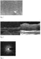
Figure. 1 illustrates the surface topography of a coating formed in accordance with one embodiment of the invention; -
Figure 2 illustrates a SEM cross-section of a coating formed in accordance with one embodiment of the invention; -
Figure. 3 illustrates the diffraction pattern of a coating formed in accordance with one embodiment of the invention; -
Figure 4 provides Rockwell indentation results of (a) 1.3 (b) 2.1 and (c) 3.8 µ m thickness of a coating formed in accordance with the invention; -
Figure 5 illustrates scratch testing results of coating formed in accordance with the invention; -
Figure 6 provides a taper cross-section of wear tracks of coatings of (a) 1.3, (b) 2.1 and (c) 3.8 µm, following ball-on-disc tests at 80 N for 720 mFigure 7 illustrates the friction coefficient of a coating in accordance with the invention sliding against WC+Co and steel ball in ball- on-disc tests in ambient condition under different normal loads; -
Figure 8 illustrates apparatus for use in the application of coatings -
Figure 9 illustrates a TEM cross sectional image of a coating formed in accordance with one embodiment of the invention; and -
Figure 10 illustrates TEM image of part of a coating formed in accordance with the invention. - It is preferred that the coating which is formed in accordance with the invention and which comprises MoS2, Ti and TiB2, is deposited by sputter depositing material from targets provided with respective magnetrons using apparatus as illustrated in
Figure 8 . - The
magnetrons 2 are provided in achamber 4 on which acarrier 6 on which thesubstrates 8 to be coated are mounted for movement, most typically by rotation of the carrier about axis 7, or, alternatively, by linear movement, is located. - The
magnetrons 2 are provided in a closed field configuration and, if necessary, one or more magnet arrays can be provided in order to allow the closed field to be formed so as to trap the electrons therein and hence improve and intensify themagnetic field 10 in which the carrier is located, with the sputtering of the materials performed using unbalanced magnetron sputtering techniques. - The apparatus includes first and
second magnetrons 2,2', each with an MoS2 target 12, amagnetron 2" with atarget 14 of Ti and afurther magnetron 2‴ with atarget 16 of TiB2 material. The pressure in thechamber 4 before deposition was around 5∼6×10⁻⁶ Torr and argon gas was introduced into the chamber and provided at a sputtering pressure of approximately 3.0×10⁻³ Torr. The distance between the targets and the substrates to be coated with the coating and which are held on the carrier is 150 mm and a pulsed DC power supply is used to provide a negative bias,, in this case about -350 V bias on the substrates, during a cleaning step in which the substrates are cleaned and at a bias in the region of -45 V during the selective sputter deposition of material from the targets during deposition. - In the first step of the coating application method a thin layer of Ti is applied to the surface of the substrates to act as an adhesion layer for the subsequent coating material to the
substrate 8. Subsequently, the coating is formed in accordance with the invention with the carrier being rotated about axis 7 so as to move the substrates in front of each of the targets12,14,12,16 in turn. A suitable speed of rotation is 4.0 rpm with the temperature of the substrates during the deposition process maintained at a temperature lower than 150 °C. - During the method, a current is applied to the Ti and TiB2 target magnetrons to cause the sputtering of the material therefrom onto the substrates and the current is varied as shown in Table 1 in order to optimize the tribological properties of the deposited coatings. The sputtering current of the MoS2 target magnetrons is set at 0.6 A, and the coating thickness is controlled to be at about 1.30 micrometres in the optimization stage.
Table 1 - sputtering current applied to the magnetrons with Ti and TiB2 targets Ti 0 0.3 0.5 0.7 0.8 TiB2 0.4 0.6 0.8 1.0 1.2 - In the method described herein the substrates used are an M42 steel test piece to allow for analysis of the tribological properties of the coating applied thereto and a Si wafer was coated for the purposes of analysis of the structure of the coating applied thereto. The adhesion of the coatings to the respective substrates was measured using a Teer ST3001 scratch/wear apparatus using a Rockwell diamond tip sliding against the coating with a load increasing by 100 N min-1 from 10 to 100 N at a sliding speed of 10 mm min-1. The scratch critical load Lc of the coating was determined by visual observation in an optical microscope and defined as the point at which coating delamination was first observed either in, or at the edge of, the scratch track. A standard Rockwell-C indentation test under a load of 150 kg was also used as an indication of adhesion (HF).
- The plastic hardness of the coatings was determined using a Fischerscope H100 tester with a Vickers indentor from the load penetration curves. Five indents were made on each sample and the data from the same was averaged. The loading/ unloading rate was 10 m N s-1, with a maximum applied load of 50 mN.
- The tribological behaviour of the coatings was determined using a Teer POD-2 pin-on-disc tester. The test used a we-eo ball of 5 mm diameter, which was loaded on top of the coated flat samples at normal loads of 20 N, 40 N or 80 N. The flat sample was rotating at a controlled speed while the ball remained at a fixed position, so that the linear sliding speed between the counterbodies was set at 200 mm s-1. The tests were conducted for 60 min. at an ambient condition with the relative humidity level of 30 ~ 40%. The wear volume was determined by producing a ball crater on the wear track.
- The surface and cross-sectional morphology and structure of the coatings were analysed using a JEOL 7000 FEG Scanning Electron Microscope (SEM) and a Philips CM20. The coatings were therefore deposited at different conditions by varying the sputtering current on the Titanium and Boron target magnetrons. As shown in Table 2, coatings with a coefficient of friction of 0.02-0.06 and a wear rate of 1× 10-17 m3 N-1 min-1in ball-on-disc tests conducted in ambient air, were achieved even with the coating thickness increased up to 4.0 µm. Furthermore, the thicker the coating that is applied then the longer the wear life as shown by the prolonged ball-on-disc test results of Table 2, which show that the wear life of the coatings in ball-on-disc test under 80 N normal load, are increased from about 2 hrs to about 12 hrs with the thickness of the coatings increased from 1.3 µ m to 3.8 µ m.
Table 2 Testing results on coatings with different thicknesses Thickness Friction Wear life µ m Lc N HF coefficient Wear rate m/Nm hr 1.3 100 2 0.03 8x10-18 2 2.1 100 3 0.04 1x10-17 6 3.8 100 4 0.04 2x10-17 12 Note: the friction and wear properties are the pin-on-disc results at a normal load of 80 N. - SEM observation of the surface as shown in
Figure 1 and the fractured cross-section as shown inFigure 2 of the coating revealed that the coating is very dense without any pores or columnar feature. The diffraction pattern of the coating inFigure 3 by TEM shows that the coating is in an amorphous structure. - The detected hardness of the coatings was found to be in the region of 900 kg/mm2 and the indentation tests show that the HF level increased as the coatings become thicker, but could still be less than
HF 4 for up to 4.0 µ m thick coatings as shown in Table 2 and inFigure 4 . The scratch tests show that the total failure load of all the coatings with different thickness is more than 100 N, although some edge chipping or isolated flakes could be seen at the beginning or in the middle of the scratch trace shown inFigure 5 . - It is therefore shown that the high wear resistance of the coating, in the region of 1×10-17m3N-1m-1 , is maintained even when the coating thickness is increased up to 4.0 micrometres as illustrated in Table 2 and
Figure 6 . - This is significant for the practical usages of the coating, as the lifetime of the coated substrate increases accordingly.
- Thus, the provision of the Ti material continues to provide the advantages of high adhesion, high humidity and wear resistance while the addition of TiB2 promotes the formation of a relatively uniform, dense, coating, so strengthening the coating which is formed and improving the high temperature performance of the coatings.
-
Figure 7 illustrates a typical friction coefficient curve of the coating in accordance with the invention sliding against a WC+Co ball in a ball-on-disc test performed in ambient air at different normal loads. The friction coefficient is lower than 0.05 even at a low load and so it is found that the higher the normal loads, the lower the friction coefficient of the coatings. - The TEM images in
Figures 9 and10 show a cross section through thecoating 20 formed in accordance with the invention, withFigure 9 including thesubstrate 8 on which the coating is formed.Figure 10 is focused on the main part of the coating formed in accordance with one embodiment of the invention and shows that the coating, in this embodiment is built up by the repeating of two bands, i.e. the dark band 22 (MoS2 and Ti); and the bright band 24 (MoS2 and Ti and TiB^. It can be seen in thedetailed portion 26 ofFigure 10 that within the bright band, bright stripes 28 (TiB2 layers) are sandwiched between the dark stripes (MoS2 and Ti). - The thickness of the dark band (MoS2 and Ti) indicates that the dark band in
Fig. 9 is composed of four basal-oriented (MoS2 and Ti) monolayers. With the inclusion of TiB2 in the bright band, the growth of the (MoS2 and Ti) layer is interrupted hence effectively two basal-oriented (MoS2 and Ti) monolayers are deposited. That is, the bright band inFigure 9 is formed with two nano-scale-basal-oriented (MoS2 and Ti) monolayers sandwiched between nano-layers of TiB2. - Thus the coating achieved in accordance with the invention achieves a dense, amorphous structure shown by SEM, XRD and TEM analyses with high load bearing capacity and excellent tribological properties of the coatings shown by ball-on-disc tests at ambient conditions and so the thickness of the coatings can be increased to 4.0 µ m while the specific wear rate of the coatings, 1×10-17 m3 N-1 m-1, is maintained at the same level as that of a 1.0 µ m thick coating.
- This is significant for the practical applications of solid lubricant coatings as the same can be applied to substrates for use in cutting and forming industries and in addition for substrates for use in heavy duty, long endurance and high reliability requirements and for substrates for use as components with high roughness.
Claims (8)
- A coating applied to a surface of a substrate wherein said coating includes MoS2 and characterised in that the coating includes repeating layers of two forms, a first form including MoS2 and Ti; and a second form including MoSz, Ti and TiBz and within this form of layer, layers of the TiBz material are sandwiched between layers of MoS2 and Ti.
- A coating according to claim 1 wherein the coating also includes one, or any combination, of carbon, Zirconium, Nickel, Cobalt, lead, Chromium, Gold, Silver, Niobium, Tantalum, and/or PTFE.
- A coating according to any of the preceding claims wherein the coating includes at least one of CaF2, BaF2, CeF3, LaF3; PbO, NiO, Cu2O, ZrOz, Ag2O, Al2O3, Sb2O3; TiB2, ZrB2, CrB2, Boron Carbide, Boron Nitride, Silicon Nitride, Titanium Nitride, Titanium Carbide, Silicon Carbide and/or Tungsten Carbide.
- A coating according to claim 1 wherein the coating includes an MoS2 layer, a metal material layer and a metal boride layer.
- A coating according to claim 1 wherein the coating materials are co-deposited to form an intimate mixture.
- A coating according to any of the preceding claims wherein the coating is formed from a plurality nano-scale multilayers which are applied to form the coating of required thickness.
- An article with a coating as described in any of claims 1-6 applied to a surface thereof.
- A method for forming a coating on a substrate surface, said method comprising the steps of:applying a layer of Ti to the surface of the substrate from at least one target including Titanium provided on a magnetron,applying a ramping layer of material during which material, in addition to Ti, starts to be applied to the Ti layer from targets of other magnetrons and provided in the form of layers of MoS2, Ti and TiB2 multilayers; and forming a top or outer layer composed of multiple layers of MoS2, + Ti and TiB2 and the sequence of operation is to operate one or more magnetrons which are associated with a target which includes Boron to sputter material therefrom before the magnetrons associated with the MoS2 targets are operated and once the operation of all of the magnetrons has commenced at least the magnetrons with the MoS2targets are continuously operated until the coating is completed and once operation of the magnetron with the target including Ti has commenced the same is operated continuously until the coating is completed characterised in that the coating includes repeating layers of two forms, a first form including MoS2 and Ti; and a second form including MoS2, Ti and TiB2 and within this form of layer, layers of the TiB2 material are sandwiched between layers of MoSz and Ti.
Applications Claiming Priority (2)
| Application Number | Priority Date | Filing Date | Title |
|---|---|---|---|
| GBGB1507524.5A GB201507524D0 (en) | 2015-05-01 | 2015-05-01 | Improvements to molybdenum containing coatings |
| PCT/GB2016/051242 WO2016178003A1 (en) | 2015-05-01 | 2016-04-29 | Coated substrate |
Publications (2)
| Publication Number | Publication Date |
|---|---|
| EP3289114A1 EP3289114A1 (en) | 2018-03-07 |
| EP3289114B1 true EP3289114B1 (en) | 2023-07-05 |
Family
ID=53489036
Family Applications (1)
| Application Number | Title | Priority Date | Filing Date |
|---|---|---|---|
| EP16728068.4A Active EP3289114B1 (en) | 2015-05-01 | 2016-04-29 | Coated substrate |
Country Status (5)
| Country | Link |
|---|---|
| US (1) | US10329657B2 (en) |
| EP (1) | EP3289114B1 (en) |
| CN (1) | CN107743527B (en) |
| GB (2) | GB201507524D0 (en) |
| WO (1) | WO2016178003A1 (en) |
Families Citing this family (9)
| Publication number | Priority date | Publication date | Assignee | Title |
|---|---|---|---|---|
| CN107686976B (en) * | 2017-08-15 | 2019-06-18 | 上海卫星装备研究所 | A kind of preparation method of molybdenum disulfide-based composite lubricating film for star |
| CN108754416B (en) * | 2018-05-28 | 2020-12-18 | 苏州瑞领克信息科技有限公司 | Low-wear guide rod applied to pneumatic actuator and surface process thereof |
| CN109735820B (en) * | 2019-03-19 | 2021-03-02 | 中国科学院兰州化学物理研究所 | A kind of gold-nickel-carbon composite conductive lubricating coating material and preparation method thereof |
| CN110747384A (en) * | 2019-11-21 | 2020-02-04 | 江苏威拉里新材料科技有限公司 | A cobalt-based metal powder |
| CN112176297A (en) * | 2020-09-25 | 2021-01-05 | 吉林大学 | A dual-phase structure composite film and its preparation method and application |
| CN112609157B (en) * | 2020-11-20 | 2023-06-16 | 江苏科技大学 | Wide-temperature-range self-lubricating nano multilayer film material and preparation method thereof |
| CN114045463B (en) * | 2021-11-23 | 2022-08-09 | 中国科学院兰州化学物理研究所 | Vacuum wide-temperature-range self-lubricating film and preparation method and application thereof |
| CN115323326B (en) * | 2022-08-17 | 2023-11-24 | 中国科学院兰州化学物理研究所 | Preparation method and application of long-life molybdenum disulfide-based composite film resistant to space atomic oxygen irradiation |
| CN117070893B (en) * | 2023-08-25 | 2024-02-02 | 安徽亚兰密封件股份有限公司 | Wear-resistant carbon-based composite film for aerospace sealing member and preparation method thereof |
Family Cites Families (15)
| Publication number | Priority date | Publication date | Assignee | Title |
|---|---|---|---|---|
| US5002798A (en) * | 1989-04-10 | 1991-03-26 | University Of Dayton | Method for forming thin solid lubricious films and film articles made thereby |
| CA2078245A1 (en) * | 1991-09-23 | 1993-03-24 | Roland Dubach | Machining tools |
| US5370778A (en) * | 1992-11-19 | 1994-12-06 | Iowa State University Research Foundation, Inc. | Method for preparing basal oriented molybdenum disulfide (MoS2) thin films |
| US6423419B1 (en) * | 1995-07-19 | 2002-07-23 | Teer Coatings Limited | Molybdenum-sulphur coatings |
| GB9514773D0 (en) | 1995-07-19 | 1995-09-20 | Teer Coatings Ltd | Methods for improving the sputter deposition of metal-sulphur coatings e.g.molybdenum disulphide(MoS2) coatings |
| AU2003222669A1 (en) * | 2002-04-22 | 2003-11-03 | Yazaki Corporation | Electrical connectors incorporating low friction coatings and methods for making them |
| US6994475B2 (en) * | 2003-03-14 | 2006-02-07 | The Timken Company | Coated rolling element bearing cages |
| WO2006035947A1 (en) * | 2004-09-30 | 2006-04-06 | Thk Co., Ltd. | Rolling guide device |
| JP4771202B2 (en) * | 2005-04-13 | 2011-09-14 | 日立金属株式会社 | Composite film having excellent adhesion and sliding properties and method for producing the same |
| US7939172B2 (en) * | 2006-05-17 | 2011-05-10 | G & H Technologies, Llc | Wear resistant vapor deposited coating, method of coating deposition and applications therefor |
| CN101393778A (en) * | 2008-11-07 | 2009-03-25 | 天津市普瑞电力科学研究有限责任公司 | Antifouling flash coating layer construction for electric RTV |
| CH705029A1 (en) * | 2011-05-27 | 2012-11-30 | Bloesch W Ag | Faced woodworking tools. |
| GB201203216D0 (en) * | 2012-02-24 | 2012-04-11 | Teer Coatings Ltd | High surface area (HSA) coatings and method for forming the same |
| CN104278241B (en) * | 2013-07-02 | 2017-10-31 | 中国科学院兰州化学物理研究所 | A kind of technology of preparing of the thin-film material with multi-environment adaptability |
| CN104498878B (en) * | 2014-12-12 | 2017-06-30 | 电子科技大学 | A kind of method for preparing molybdenum disulfide film |
-
2015
- 2015-05-01 GB GBGB1507524.5A patent/GB201507524D0/en not_active Ceased
-
2016
- 2016-04-29 GB GB1607516.0A patent/GB2539767B/en active Active
- 2016-04-29 CN CN201680034271.6A patent/CN107743527B/en active Active
- 2016-04-29 US US15/570,850 patent/US10329657B2/en active Active
- 2016-04-29 EP EP16728068.4A patent/EP3289114B1/en active Active
- 2016-04-29 WO PCT/GB2016/051242 patent/WO2016178003A1/en not_active Ceased
Also Published As
| Publication number | Publication date |
|---|---|
| CN107743527A (en) | 2018-02-27 |
| GB201607516D0 (en) | 2016-06-15 |
| US10329657B2 (en) | 2019-06-25 |
| EP3289114A1 (en) | 2018-03-07 |
| WO2016178003A1 (en) | 2016-11-10 |
| CN107743527B (en) | 2020-12-15 |
| GB2539767B (en) | 2019-10-30 |
| US20180148825A1 (en) | 2018-05-31 |
| GB2539767A (en) | 2016-12-28 |
| GB201507524D0 (en) | 2015-06-17 |
Similar Documents
| Publication | Publication Date | Title |
|---|---|---|
| US10329657B2 (en) | Coated substrate | |
| Yang et al. | Deposition and tribological behaviour of sputtered carbon hard coatings | |
| CN111511490B (en) | Clad Cutting Tools | |
| EP2362000A1 (en) | Hard multilayer film formed body and method for manufacturing same | |
| EP1939327A1 (en) | Multilayered coated cutting tool | |
| EP3828311A1 (en) | Razor blade coating | |
| EP2839051A1 (en) | High performance tools exhibiting reduced crater wear in particular by dry machining operations | |
| Montero-Ocampo et al. | Effect of codeposition parameters on the hardness and adhesion of TiVN coatings | |
| JP7277821B2 (en) | coated cutting tools | |
| Endrino et al. | Magnetron sputter deposition of WC–Ag and TiC–Ag coatings and their frictional properties in vacuum environments | |
| JP4357160B2 (en) | Sputtering target, hard coating using the same, and hard film coating member | |
| Stanishevsky et al. | Tribological properties of composite Ti (N, O, C) coatings containing hard amorphous carbon layers | |
| JP4916021B2 (en) | Film | |
| CN113874143B (en) | Coated cutting tools | |
| Kretschmer et al. | High-temperature tribological behavior of high-entropy sublattice oxide, nitride, and diboride coatings | |
| EP3842169A1 (en) | Cutting tool | |
| KR20250126732A (en) | coated cutting tools | |
| JP7277820B2 (en) | coated cutting tools | |
| EP3842170A1 (en) | Cutting tool | |
| Hyakutake et al. | Mechanical properties of TiN-TiC mixed crystal films | |
| EP4732972A1 (en) | Coated cutting tool | |
| KR20260019473A (en) | coated cutting tools | |
| KR20260018827A (en) | coated cutting tools | |
| Gołombek et al. | Characterization of Nanocrystalline AlTiSiN Coatings Deposited by a LARCCAE Process | |
| JP3962911B2 (en) | Surface coated cemented carbide cutting tool with excellent chipping resistance with hard coating layer under heavy cutting conditions |
Legal Events
| Date | Code | Title | Description |
|---|---|---|---|
| STAA | Information on the status of an ep patent application or granted ep patent |
Free format text: STATUS: THE INTERNATIONAL PUBLICATION HAS BEEN MADE |
|
| PUAI | Public reference made under article 153(3) epc to a published international application that has entered the european phase |
Free format text: ORIGINAL CODE: 0009012 |
|
| STAA | Information on the status of an ep patent application or granted ep patent |
Free format text: STATUS: REQUEST FOR EXAMINATION WAS MADE |
|
| 17P | Request for examination filed |
Effective date: 20171108 |
|
| AK | Designated contracting states |
Kind code of ref document: A1 Designated state(s): AL AT BE BG CH CY CZ DE DK EE ES FI FR GB GR HR HU IE IS IT LI LT LU LV MC MK MT NL NO PL PT RO RS SE SI SK SM TR |
|
| AX | Request for extension of the european patent |
Extension state: BA ME |
|
| DAV | Request for validation of the european patent (deleted) | ||
| DAX | Request for extension of the european patent (deleted) | ||
| STAA | Information on the status of an ep patent application or granted ep patent |
Free format text: STATUS: EXAMINATION IS IN PROGRESS |
|
| 17Q | First examination report despatched |
Effective date: 20180926 |
|
| REG | Reference to a national code |
Ref country code: DE Ref legal event code: R079 Free format text: PREVIOUS MAIN CLASS: C23C0014060000 Ipc: C23C0014020000 Ref country code: DE Ref legal event code: R079 Ref document number: 602016080797 Country of ref document: DE Free format text: PREVIOUS MAIN CLASS: C23C0014060000 Ipc: C23C0014020000 |
|
| GRAP | Despatch of communication of intention to grant a patent |
Free format text: ORIGINAL CODE: EPIDOSNIGR1 |
|
| STAA | Information on the status of an ep patent application or granted ep patent |
Free format text: STATUS: GRANT OF PATENT IS INTENDED |
|
| RIC1 | Information provided on ipc code assigned before grant |
Ipc: C23C 28/00 20060101ALI20230215BHEP Ipc: C23C 14/56 20060101ALI20230215BHEP Ipc: C23C 14/35 20060101ALI20230215BHEP Ipc: C23C 14/34 20060101ALI20230215BHEP Ipc: C23C 14/06 20060101ALI20230215BHEP Ipc: C23C 14/02 20060101AFI20230215BHEP |
|
| INTG | Intention to grant announced |
Effective date: 20230309 |
|
| GRAS | Grant fee paid |
Free format text: ORIGINAL CODE: EPIDOSNIGR3 |
|
| GRAJ | Information related to disapproval of communication of intention to grant by the applicant or resumption of examination proceedings by the epo deleted |
Free format text: ORIGINAL CODE: EPIDOSDIGR1 |
|
| GRAL | Information related to payment of fee for publishing/printing deleted |
Free format text: ORIGINAL CODE: EPIDOSDIGR3 |
|
| STAA | Information on the status of an ep patent application or granted ep patent |
Free format text: STATUS: EXAMINATION IS IN PROGRESS |
|
| GRAP | Despatch of communication of intention to grant a patent |
Free format text: ORIGINAL CODE: EPIDOSNIGR1 |
|
| STAA | Information on the status of an ep patent application or granted ep patent |
Free format text: STATUS: GRANT OF PATENT IS INTENDED |
|
| GRAA | (expected) grant |
Free format text: ORIGINAL CODE: 0009210 |
|
| STAA | Information on the status of an ep patent application or granted ep patent |
Free format text: STATUS: THE PATENT HAS BEEN GRANTED |
|
| INTC | Intention to grant announced (deleted) | ||
| P01 | Opt-out of the competence of the unified patent court (upc) registered |
Effective date: 20230403 |
|
| INTG | Intention to grant announced |
Effective date: 20230525 |
|
| AK | Designated contracting states |
Kind code of ref document: B1 Designated state(s): AL AT BE BG CH CY CZ DE DK EE ES FI FR GB GR HR HU IE IS IT LI LT LU LV MC MK MT NL NO PL PT RO RS SE SI SK SM TR |
|
| REG | Reference to a national code |
Ref country code: CH Ref legal event code: EP |
|
| REG | Reference to a national code |
Ref country code: AT Ref legal event code: REF Ref document number: 1584904 Country of ref document: AT Kind code of ref document: T Effective date: 20230715 |
|
| REG | Reference to a national code |
Ref country code: DE Ref legal event code: R096 Ref document number: 602016080797 Country of ref document: DE |
|
| REG | Reference to a national code |
Ref country code: IE Ref legal event code: FG4D |
|
| REG | Reference to a national code |
Ref country code: LT Ref legal event code: MG9D |
|
| REG | Reference to a national code |
Ref country code: NL Ref legal event code: MP Effective date: 20230705 |
|
| REG | Reference to a national code |
Ref country code: AT Ref legal event code: MK05 Ref document number: 1584904 Country of ref document: AT Kind code of ref document: T Effective date: 20230705 |
|
| PG25 | Lapsed in a contracting state [announced via postgrant information from national office to epo] |
Ref country code: NL Free format text: LAPSE BECAUSE OF FAILURE TO SUBMIT A TRANSLATION OF THE DESCRIPTION OR TO PAY THE FEE WITHIN THE PRESCRIBED TIME-LIMIT Effective date: 20230705 |
|
| PG25 | Lapsed in a contracting state [announced via postgrant information from national office to epo] |
Ref country code: GR Free format text: LAPSE BECAUSE OF FAILURE TO SUBMIT A TRANSLATION OF THE DESCRIPTION OR TO PAY THE FEE WITHIN THE PRESCRIBED TIME-LIMIT Effective date: 20231006 |
|
| PG25 | Lapsed in a contracting state [announced via postgrant information from national office to epo] |
Ref country code: ES Free format text: LAPSE BECAUSE OF FAILURE TO SUBMIT A TRANSLATION OF THE DESCRIPTION OR TO PAY THE FEE WITHIN THE PRESCRIBED TIME-LIMIT Effective date: 20230705 |
|
| PG25 | Lapsed in a contracting state [announced via postgrant information from national office to epo] |
Ref country code: IS Free format text: LAPSE BECAUSE OF FAILURE TO SUBMIT A TRANSLATION OF THE DESCRIPTION OR TO PAY THE FEE WITHIN THE PRESCRIBED TIME-LIMIT Effective date: 20231105 |
|
| PG25 | Lapsed in a contracting state [announced via postgrant information from national office to epo] |
Ref country code: SE Free format text: LAPSE BECAUSE OF FAILURE TO SUBMIT A TRANSLATION OF THE DESCRIPTION OR TO PAY THE FEE WITHIN THE PRESCRIBED TIME-LIMIT Effective date: 20230705 Ref country code: RS Free format text: LAPSE BECAUSE OF FAILURE TO SUBMIT A TRANSLATION OF THE DESCRIPTION OR TO PAY THE FEE WITHIN THE PRESCRIBED TIME-LIMIT Effective date: 20230705 Ref country code: PT Free format text: LAPSE BECAUSE OF FAILURE TO SUBMIT A TRANSLATION OF THE DESCRIPTION OR TO PAY THE FEE WITHIN THE PRESCRIBED TIME-LIMIT Effective date: 20231106 Ref country code: NO Free format text: LAPSE BECAUSE OF FAILURE TO SUBMIT A TRANSLATION OF THE DESCRIPTION OR TO PAY THE FEE WITHIN THE PRESCRIBED TIME-LIMIT Effective date: 20231005 Ref country code: LV Free format text: LAPSE BECAUSE OF FAILURE TO SUBMIT A TRANSLATION OF THE DESCRIPTION OR TO PAY THE FEE WITHIN THE PRESCRIBED TIME-LIMIT Effective date: 20230705 Ref country code: LT Free format text: LAPSE BECAUSE OF FAILURE TO SUBMIT A TRANSLATION OF THE DESCRIPTION OR TO PAY THE FEE WITHIN THE PRESCRIBED TIME-LIMIT Effective date: 20230705 Ref country code: IS Free format text: LAPSE BECAUSE OF FAILURE TO SUBMIT A TRANSLATION OF THE DESCRIPTION OR TO PAY THE FEE WITHIN THE PRESCRIBED TIME-LIMIT Effective date: 20231105 Ref country code: HR Free format text: LAPSE BECAUSE OF FAILURE TO SUBMIT A TRANSLATION OF THE DESCRIPTION OR TO PAY THE FEE WITHIN THE PRESCRIBED TIME-LIMIT Effective date: 20230705 Ref country code: GR Free format text: LAPSE BECAUSE OF FAILURE TO SUBMIT A TRANSLATION OF THE DESCRIPTION OR TO PAY THE FEE WITHIN THE PRESCRIBED TIME-LIMIT Effective date: 20231006 Ref country code: FI Free format text: LAPSE BECAUSE OF FAILURE TO SUBMIT A TRANSLATION OF THE DESCRIPTION OR TO PAY THE FEE WITHIN THE PRESCRIBED TIME-LIMIT Effective date: 20230705 Ref country code: ES Free format text: LAPSE BECAUSE OF FAILURE TO SUBMIT A TRANSLATION OF THE DESCRIPTION OR TO PAY THE FEE WITHIN THE PRESCRIBED TIME-LIMIT Effective date: 20230705 Ref country code: AT Free format text: LAPSE BECAUSE OF FAILURE TO SUBMIT A TRANSLATION OF THE DESCRIPTION OR TO PAY THE FEE WITHIN THE PRESCRIBED TIME-LIMIT Effective date: 20230705 |
|
| PG25 | Lapsed in a contracting state [announced via postgrant information from national office to epo] |
Ref country code: PL Free format text: LAPSE BECAUSE OF FAILURE TO SUBMIT A TRANSLATION OF THE DESCRIPTION OR TO PAY THE FEE WITHIN THE PRESCRIBED TIME-LIMIT Effective date: 20230705 |
|
| REG | Reference to a national code |
Ref country code: DE Ref legal event code: R097 Ref document number: 602016080797 Country of ref document: DE |
|
| PG25 | Lapsed in a contracting state [announced via postgrant information from national office to epo] |
Ref country code: SM Free format text: LAPSE BECAUSE OF FAILURE TO SUBMIT A TRANSLATION OF THE DESCRIPTION OR TO PAY THE FEE WITHIN THE PRESCRIBED TIME-LIMIT Effective date: 20230705 Ref country code: RO Free format text: LAPSE BECAUSE OF FAILURE TO SUBMIT A TRANSLATION OF THE DESCRIPTION OR TO PAY THE FEE WITHIN THE PRESCRIBED TIME-LIMIT Effective date: 20230705 Ref country code: EE Free format text: LAPSE BECAUSE OF FAILURE TO SUBMIT A TRANSLATION OF THE DESCRIPTION OR TO PAY THE FEE WITHIN THE PRESCRIBED TIME-LIMIT Effective date: 20230705 Ref country code: DK Free format text: LAPSE BECAUSE OF FAILURE TO SUBMIT A TRANSLATION OF THE DESCRIPTION OR TO PAY THE FEE WITHIN THE PRESCRIBED TIME-LIMIT Effective date: 20230705 Ref country code: CZ Free format text: LAPSE BECAUSE OF FAILURE TO SUBMIT A TRANSLATION OF THE DESCRIPTION OR TO PAY THE FEE WITHIN THE PRESCRIBED TIME-LIMIT Effective date: 20230705 Ref country code: SK Free format text: LAPSE BECAUSE OF FAILURE TO SUBMIT A TRANSLATION OF THE DESCRIPTION OR TO PAY THE FEE WITHIN THE PRESCRIBED TIME-LIMIT Effective date: 20230705 |
|
| PLBE | No opposition filed within time limit |
Free format text: ORIGINAL CODE: 0009261 |
|
| STAA | Information on the status of an ep patent application or granted ep patent |
Free format text: STATUS: NO OPPOSITION FILED WITHIN TIME LIMIT |
|
| PG25 | Lapsed in a contracting state [announced via postgrant information from national office to epo] |
Ref country code: IT Free format text: LAPSE BECAUSE OF FAILURE TO SUBMIT A TRANSLATION OF THE DESCRIPTION OR TO PAY THE FEE WITHIN THE PRESCRIBED TIME-LIMIT Effective date: 20230705 |
|
| 26N | No opposition filed |
Effective date: 20240408 |
|
| PG25 | Lapsed in a contracting state [announced via postgrant information from national office to epo] |
Ref country code: SI Free format text: LAPSE BECAUSE OF FAILURE TO SUBMIT A TRANSLATION OF THE DESCRIPTION OR TO PAY THE FEE WITHIN THE PRESCRIBED TIME-LIMIT Effective date: 20230705 |
|
| PG25 | Lapsed in a contracting state [announced via postgrant information from national office to epo] |
Ref country code: BG Free format text: LAPSE BECAUSE OF FAILURE TO SUBMIT A TRANSLATION OF THE DESCRIPTION OR TO PAY THE FEE WITHIN THE PRESCRIBED TIME-LIMIT Effective date: 20230705 |
|
| PG25 | Lapsed in a contracting state [announced via postgrant information from national office to epo] |
Ref country code: MC Free format text: LAPSE BECAUSE OF FAILURE TO SUBMIT A TRANSLATION OF THE DESCRIPTION OR TO PAY THE FEE WITHIN THE PRESCRIBED TIME-LIMIT Effective date: 20230705 |
|
| PG25 | Lapsed in a contracting state [announced via postgrant information from national office to epo] |
Ref country code: MC Free format text: LAPSE BECAUSE OF FAILURE TO SUBMIT A TRANSLATION OF THE DESCRIPTION OR TO PAY THE FEE WITHIN THE PRESCRIBED TIME-LIMIT Effective date: 20230705 Ref country code: BG Free format text: LAPSE BECAUSE OF FAILURE TO SUBMIT A TRANSLATION OF THE DESCRIPTION OR TO PAY THE FEE WITHIN THE PRESCRIBED TIME-LIMIT Effective date: 20230705 |
|
| REG | Reference to a national code |
Ref country code: CH Ref legal event code: PL |
|
| PG25 | Lapsed in a contracting state [announced via postgrant information from national office to epo] |
Ref country code: LU Free format text: LAPSE BECAUSE OF NON-PAYMENT OF DUE FEES Effective date: 20240429 |
|
| REG | Reference to a national code |
Ref country code: BE Ref legal event code: MM Effective date: 20240430 |
|
| PG25 | Lapsed in a contracting state [announced via postgrant information from national office to epo] |
Ref country code: LU Free format text: LAPSE BECAUSE OF NON-PAYMENT OF DUE FEES Effective date: 20240429 |
|
| PG25 | Lapsed in a contracting state [announced via postgrant information from national office to epo] |
Ref country code: BE Free format text: LAPSE BECAUSE OF NON-PAYMENT OF DUE FEES Effective date: 20240430 |
|
| PG25 | Lapsed in a contracting state [announced via postgrant information from national office to epo] |
Ref country code: BE Free format text: LAPSE BECAUSE OF NON-PAYMENT OF DUE FEES Effective date: 20240430 Ref country code: CH Free format text: LAPSE BECAUSE OF NON-PAYMENT OF DUE FEES Effective date: 20240430 |
|
| PGFP | Annual fee paid to national office [announced via postgrant information from national office to epo] |
Ref country code: DE Payment date: 20250326 Year of fee payment: 10 |
|
| PG25 | Lapsed in a contracting state [announced via postgrant information from national office to epo] |
Ref country code: CY Free format text: LAPSE BECAUSE OF FAILURE TO SUBMIT A TRANSLATION OF THE DESCRIPTION OR TO PAY THE FEE WITHIN THE PRESCRIBED TIME-LIMIT; INVALID AB INITIO Effective date: 20160429 |
|
| PG25 | Lapsed in a contracting state [announced via postgrant information from national office to epo] |
Ref country code: HU Free format text: LAPSE BECAUSE OF FAILURE TO SUBMIT A TRANSLATION OF THE DESCRIPTION OR TO PAY THE FEE WITHIN THE PRESCRIBED TIME-LIMIT; INVALID AB INITIO Effective date: 20160429 |
|
| PGFP | Annual fee paid to national office [announced via postgrant information from national office to epo] |
Ref country code: GB Payment date: 20260217 Year of fee payment: 11 |
|
| PGFP | Annual fee paid to national office [announced via postgrant information from national office to epo] |
Ref country code: IE Payment date: 20260217 Year of fee payment: 11 |
|
| PGFP | Annual fee paid to national office [announced via postgrant information from national office to epo] |
Ref country code: FR Payment date: 20260218 Year of fee payment: 11 |