EP3288800B1 - A cable support - Google Patents
A cable support Download PDFInfo
- Publication number
- EP3288800B1 EP3288800B1 EP16720519.4A EP16720519A EP3288800B1 EP 3288800 B1 EP3288800 B1 EP 3288800B1 EP 16720519 A EP16720519 A EP 16720519A EP 3288800 B1 EP3288800 B1 EP 3288800B1
- Authority
- EP
- European Patent Office
- Prior art keywords
- locking member
- cable support
- mounting section
- support
- mounting
- Prior art date
- Legal status (The legal status is an assumption and is not a legal conclusion. Google has not performed a legal analysis and makes no representation as to the accuracy of the status listed.)
- Active
Links
Images




Classifications
-
- B—PERFORMING OPERATIONS; TRANSPORTING
- B60—VEHICLES IN GENERAL
- B60R—VEHICLES, VEHICLE FITTINGS, OR VEHICLE PARTS, NOT OTHERWISE PROVIDED FOR
- B60R16/00—Electric or fluid circuits specially adapted for vehicles and not otherwise provided for; Arrangement of elements of electric or fluid circuits specially adapted for vehicles and not otherwise provided for
- B60R16/02—Electric or fluid circuits specially adapted for vehicles and not otherwise provided for; Arrangement of elements of electric or fluid circuits specially adapted for vehicles and not otherwise provided for electric constitutive elements
- B60R16/0207—Wire harnesses
- B60R16/0215—Protecting, fastening and routing means therefor
-
- F—MECHANICAL ENGINEERING; LIGHTING; HEATING; WEAPONS; BLASTING
- F16—ENGINEERING ELEMENTS AND UNITS; GENERAL MEASURES FOR PRODUCING AND MAINTAINING EFFECTIVE FUNCTIONING OF MACHINES OR INSTALLATIONS; THERMAL INSULATION IN GENERAL
- F16L—PIPES; JOINTS OR FITTINGS FOR PIPES; SUPPORTS FOR PIPES, CABLES OR PROTECTIVE TUBING; MEANS FOR THERMAL INSULATION IN GENERAL
- F16L3/00—Supports for pipes, cables or protective tubing, e.g. hangers, holders, clamps, cleats, clips, brackets
- F16L3/16—Supports for pipes, cables or protective tubing, e.g. hangers, holders, clamps, cleats, clips, brackets with special provision allowing movement of the pipe
-
- F—MECHANICAL ENGINEERING; LIGHTING; HEATING; WEAPONS; BLASTING
- F16—ENGINEERING ELEMENTS AND UNITS; GENERAL MEASURES FOR PRODUCING AND MAINTAINING EFFECTIVE FUNCTIONING OF MACHINES OR INSTALLATIONS; THERMAL INSULATION IN GENERAL
- F16L—PIPES; JOINTS OR FITTINGS FOR PIPES; SUPPORTS FOR PIPES, CABLES OR PROTECTIVE TUBING; MEANS FOR THERMAL INSULATION IN GENERAL
- F16L3/00—Supports for pipes, cables or protective tubing, e.g. hangers, holders, clamps, cleats, clips, brackets
- F16L3/16—Supports for pipes, cables or protective tubing, e.g. hangers, holders, clamps, cleats, clips, brackets with special provision allowing movement of the pipe
- F16L3/18—Supports for pipes, cables or protective tubing, e.g. hangers, holders, clamps, cleats, clips, brackets with special provision allowing movement of the pipe allowing movement in axial direction
-
- H—ELECTRICITY
- H02—GENERATION; CONVERSION OR DISTRIBUTION OF ELECTRIC POWER
- H02G—INSTALLATION OF ELECTRIC CABLES OR LINES, OR OF COMBINED OPTICAL AND ELECTRIC CABLES OR LINES
- H02G3/00—Installations of electric cables or lines or protective tubing therefor in or on buildings, equivalent structures or vehicles
- H02G3/30—Installations of cables or lines on walls, floors or ceilings
-
- H—ELECTRICITY
- H02—GENERATION; CONVERSION OR DISTRIBUTION OF ELECTRIC POWER
- H02G—INSTALLATION OF ELECTRIC CABLES OR LINES, OR OF COMBINED OPTICAL AND ELECTRIC CABLES OR LINES
- H02G3/00—Installations of electric cables or lines or protective tubing therefor in or on buildings, equivalent structures or vehicles
- H02G3/30—Installations of cables or lines on walls, floors or ceilings
- H02G3/32—Installations of cables or lines on walls, floors or ceilings using mounting clamps
Definitions
- the present invention relates to a cable support, and in particular to a bracket for securing electrical cables within a vehicle.
- the reverse side of the tabs 240 include a recessed region 246 surrounded by a thicker peripheral section 248. Similarly a recessed region 250 is defined between the body section 216 and the blade 202. The recessed regions 246 and 250 reduce material and therefore cost of the cable support 201.
Landscapes
- Engineering & Computer Science (AREA)
- Mechanical Engineering (AREA)
- General Engineering & Computer Science (AREA)
- Architecture (AREA)
- Civil Engineering (AREA)
- Structural Engineering (AREA)
- Installation Of Indoor Wiring (AREA)
- Supports For Pipes And Cables (AREA)
Description
- The present invention relates to a cable support, and in particular to a bracket for securing electrical cables within a vehicle.
- Body panels such as doors for passenger vehicles typically comprise a main body forming the structure of the door or other panel, and an interior trim panel assembly. The trim panel assembly provides an aesthetically pleasing appearance to the interior surface of the door that also enables the mechanical and electrical elements of the door to be concealed from view. It is known to use trim panels for obscuring and protecting electrical wiring. Wiring is supported and channelled behind the trim panel. It is important that the wiring is held securely in place within the void behind the trim panel to avoid rattle and to protect the wiring and associated connections from damage. The inner surface of a door panel, as with other body panels, is typically devoid of connection features such as eyes for cable ties that could be used to secure the wiring in position.
- A trim panel includes an inner surface facing into the void towards the main body panel, and an outer surface facing outwardly into the vehicle. A known solution is to secure the wiring to the inner surface of the trim panel. Small eyelets and holes required for fasteners such as cable ties present difficulties in moulding. Therefore, a common solution is to mould a stud projecting from the inner surface of the trim panel, and to secure to the stud a substantially flat, elongate support bar to which the wiring may be secured via adhesive tape or other means.
-
Figure 1 shows a moulded plastic cable support of the prior art. The cable support 1 includes anelongate bar 2 and a clip portion 4. The clip portion 4 extends from an edge of thesupport bar 2 in a substantially perpendicular direction, with thebar 2 and clip section 4 defining a substantially T-shaped arrangement. The wiring is aligned along the length of thebar 2 and taped to the bar to hold it in position. The clip section 4 includes acylindrical mount 6 having an inner bore that is arranged to receive a corresponding cylindrical moulded stud of the trim panel. A substantially squareshaped chamber 8 is located at one end of themount 6 through which the bore continues. Aslot 10 is formed in the lower edge of thechamber 8 into which ametal insert 12 is received. Theinsert 12 has a square shape corresponding to the shape of the inner volume of the chamber to prevent movement of theinsert 12 within thechamber 8. The insert includes acentral aperture 14 that aligns with the bore. The diameter of theaperture 14 is selected provide an interference fit over the stud of the trim panel. As the cable support 1 is pushed onto the stud, the edge of theaperture 14 of the metal insert bites into plastic stud causing linear scoring of the stud as the locking member is moved axially into position. More problematically, any rotational forces applied to the support bar cause the bar and the locking member to rotate relative to the stud. During rotation the locking member rotationally scores the stud, leading to loosening of the locking member and potential failure of the stud. - It is therefore desirable to provide an improved cable support which addresses the above described problems and/or which offers improvements generally.
- According to the present invention there is provided a cable support as described in the accompanying claims.
- In an embodiment of the invention there is provided a cable support comprising a support member for supporting a cable or cables secured thereto. A mounting section is provided for securing the cable support to a corresponding mounting spigot, the mounting section comprising a bore for receiving said spigot. A locking member is provided having an aperture formed therein for receiving said spigot, the locking member being connected to the mounting section in axial alignment with the bore. The locking member is rotatably connected to the mounting section such that the mounting section and support member are rotatable relative to the locking member. In this way any rotational forces applied to the support member and/or the main body cause the support member and/or the main body to rotate relative to the locking member, while the locking member remains rotationally fixed relative to the mounting spigot. Preventing the support member and/or the main body from imparting a rotational force to the locking member ensures that the locking member does not rotationally score the mounting spigot, thereby preventing the locking member from loosening over time and/or causing failure of the mounting spigot.
- The locking member is annular having an inner diameter configured to provide an interference fit with the mounting spigot when inserted thereon. The annular shape provides a circular outer peripheral edge that is able to rotate within the corresponding circular cross section of the bore allowing relative rotation between the locking member and the main body, while the circular inner peripheral edge corresponds to the circular cross section of the mounting spigot.
- The locking member is mounted within the bore of the mounting section. The locking member may inserted into the mounting section in the insertion direction with the mounting section including one or more stop members to limit axial insertion of the locking member located at the inner end of the bore. One or more retaining members are also provided to prevent removal of the locking member in the opposite direction once inserted, with the locking member being retained between the retaining member and the stop member or members.
- Preferably the support member is an elongate blade that provides a support surface of substantial length to which the cables may be secured by adhesive tape or otherwise.
- The cable support has a support surface to which the cable or cables are secured, and the cable support surface preferably has a concave profile in a direction transverse to the length of the blade. The concave profile corresponds to the curved surface of the cables, and increases the surface contact between the blade and the cables.
- The locking member comprises a plurality of radially extending elongate slots extending radially outwards from the radially inner edge defining a plurality of annularly arranged teeth.
- The bore of the main body includes an innermost opening and an outermost opening with an insertion direction being defined in a direction extending from the outermost opening towards the innermost opening which in use is the direction in which the mounting section is inserted onto the mounting spigot, wherein at least the radially innermost portion of the teeth are angled in the axial direction with the locking member being mounted to the mounting section such that the teeth are angled in the opposite axial direction to the insertion direction to inhibit axial removal of the locking member from the mounting spigot.
- The annular locking member is preferably formed of metal, which allows the locking member to lock into the surface of the softer plastic mounting spigot.
- The one or more retaining members is preferably a retaining clip arranged to flex in the axial direction from a retaining position to an insertion position, the clip being arranged to flex to the insertion position on insertion of the locking member, and to return to the retaining position following insertion of the locking member. The retaining clips preferably have a tapered leading outer edge.
- The axial spacing between the stop member and retaining member is preferably substantially equal to the thickness of the locking member to limit axial movement of the locking member within the bore. The locking ring preferably includes a wall at its peripheral edge extending axially away from the planar surface of the ring, the thickness of the locking member being defined by the height of the wall.
- The at least one stop member preferably includes an curved inner surface having a radius corresponding to the inner radius of the locking member such that the inner edge of the locking member at the stop member are radially aligned.
- The mounting section may include one or more radially extending engagement tabs arranged having an engagement surface which in use faces away from the insertion direction, the one or more tabs arranged to allow pressure to be applied thereto by the user in the insertion direction to force the cable support onto the spigot.
- The engagement tabs are preferably arranged on diametrically opposed sides of the mounting section, and preferably extend radially outwards in a direction parallel with the longitudinal axis of the support bar.
- The mounting section includes a lower surface and an upper surface which surround the bore. The height of the mounting section and the spigot are selected such that when the mounting section is secured to the spigot the spigot does not project past the upper surface of the mounting section.
- The engagement tabs are arranged to project laterally from the upper end of the mounting section.
- Preferably the upper surface of the mounting section is spaced vertically above the upper surface of the cable support member. The mounting section preferably includes a body section having a cylindrical collar section extending upwardly above the height of the support member with the engagement tabs extending laterally from the upper end of the collar section.
- The height of the mounting section is selected to be greater than the effective height of the spigot, the effective height being the height to which the spigot projects from the support substrate to which it is mounted.
- The present invention will now be described by way of example only with reference to the following illustrative figures in which:
-
Figure 1 shows a cable support of the prior art; -
Figure 1a shows the metal insert of the cable support ofFigure 1 ; -
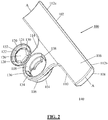
Figure 2 shows an exploded view of a cable support according to an embodiment of the invention; -
Figure 3 is a reverse view of the arrangement ofFigure 2 ; and -
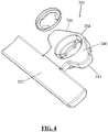
Figure 4 shows a cable support according to an alternative embodiment of the invention; -
Figure 5 shows a reverse view of the arrangement ofFigure 4 ; and -
Figure 6 shows the cable support ofFigures 4 and5 inserted on a support spigot of a vehicle panel; -
Figure 7 is a side view of a cable support according to another embodiment of the invention; and -
Figure 8 is a perspective view of the arrangement ofFigure 8 . - Referring to
Figure 2 there is provided anelectrical cable support 100 including an elongaterectangular bar section 102 defining a support blade, and aclip section 104 for mounting the wiring support to a corresponding mounting stud or spigot. The stud may be integrally moulded with or mounted to a support substrate. Thesupport blade 102 has an elongate rectangular form with a longitudinal axis A-A. Theblade 102 includes a mountingsurface 106 which in use faces away from the trim panel, and away from the insertion direction, and a correspondinginner surface 108. In use the wiring is secured to the mountingsurface 106. The mountingsurface 106 has a concave scalloped profile in the direction transverse to the longitudinal axis for accommodating the curved profile of a wiring bundle. Theclip section 104 extends from thelower edge 110 of theblade 102 and is located centrally along the length of theblade 102. End portions 112 of theblade 102 extend longitudinally outwards of theclip section 104 in opposing directions. - The clip or mounting
section 104 includes afront flange section 114 that secures at its upper edge to thelower edge 110 of theblade 102. A cylindricalmain body section 116 extends from the rear surface of theflange section 114. Abore 118 extends through theouter flange section 114 andcylindrical body 116. Thebore 118 is open at both ends. The diameter of thebore 118 is sized to receive ametal locking disc 120 in a close fit in which there is little or no lateral movement between thebore 118 and the peripheral edge of thedisc 120, while thedisc 120 is able to rotationally move relative to thebore 118. - The
locking disc 120 includes a peripheral reinforcingwall 122 and an annularplanar surface 124 extending radially inwards from thewall 122.Aperture 126 is defined by the inner edge of the annularplanar section 124. The plurality ofteeth 128 extend radially inwards from the inner edge of the annularplanar section 124 into theaperture 126. A series of circumferentially arrangedslits 130 interspace theteeth 128. Thelocking ring 120 includes a radial axis and a rotational axis which in use is coaxial with the longitudinal axis of the stud, and which extends through the centre of theaperture 126 perpendicular to the radial axis. The radial axis of thelocking ring 120 defines the insertion axis, which in use is the axis along which the locking ring and bore are inserted over the mounting spigot. - The
teeth 128 are angled in the axial direction such that they slope away from the planarannular portion 124. Theteeth 128 are angled rearwardly relative to the insertion direction of the locking ring. The radially inner edges of theteeth 132 define an inner diameter to thelocking disc 120 which is configured to have an interference fit with the stud. As thelocking wheel 120 is inserted onto the stud in the insertion direction, theteeth 128 are able to flex away from the surface of the stud due to their rearwardly angled configuration to prevent or mitigate linear scoring along the length of the stud, with the teeth having a return bias that urges them against the stud. Once inserted to the required longitudinal position any attempt to withdraw the locking ring in the opposing direction causes theinner edges 132 of theteeth 128 to dig into the surface of the stud to axially lock the ring in position. The interspaced arrangement of theteeth 128 also allows theteeth 128 to key into the surface of the stud which prevents rotation of thelocking wheel 128 relative to the stud. -
Rear stop members 134 are located at the axially rear end of thebore 118 at the insertion end. Thestop members 134 extend radially into the bore axially locate thelocking ring 128 within themain body 104 and stop the locking ring from passing through thebore 118. As shown inFigure 3 , thestop members 134 are diametrically opposed and each extend in a circumferential direction around approximately one quarter of the bore edge. This arrangement advantageously reduces material. The curved radially inner edges of the stop members have a radius substantially equal to the radius of the inner edge of theteeth 128 to provide a two-point contact along the length of the spigot. Retainingclips 136 are located at the opposing end of thebore 118. The retaining clips 136 include a taperedleading edge 138 which is engaged by the lockingring 128 as thelocking ring 128 is inserted axially into themain body 116. The retaining clips 136 are flexible and able to axially flex as thelocking ring 128 is inserted. Once inserted the retainingclips 136 return to their original position and the upper edge of thewall 122 engages against the axially innermost edge of the retaining clips to prevent retraction of thelocking ring 120. - The axial spacing between the axially outer facing surface of the
stop number 134 and the axially inner facing surface of the retaining clips 136 is selected such that are substantially equal to the height of thewall 122 of the retainingclip 120 such that thelocking ring 120 is axially retained with limited movement between the retainingclips 136 and thestop members 134 - The
locking ring 120 is held between the retainingclips 136 and thestop members 138 within thebore 118 with the axial and radial fit being selected as such that thelocking ring 120 is able to rotate within thebore 118. As such, themain body 104 and blade to which it is attached 102 are able to rotate relative to theblocking ring 120 while the locking ring remains rotationally fixed relative to the spigot. In use thelocking ring 120 is inserted into thebore 118 and retained therein. Thewiring support 100 is then inserted over the mounting stud with the mounting stud being inserted into thebore 118 and through thelocking ring 120 retained therein. Thewiring support 100 is urged along the stud to the desired axial location with thelocking ring 120 then locking the cable support in this axial position. In this location the rearward surface of the main body of thewiring support 100 abuts the trim panel from which the stud extends. - The rear surface of the
main body section 116 extends rearwardly of the rear surface of the main part of theblade 102. Therefore when the rear surface of themain body section 116 abuts the trim panel the rear surface of theblade 102 is spaced from the trim panel. To avoid stress on the join between theflange section 114 and theblade 102 if theblade 102 would be forced rearwardly theblade 102 is provided with aabutment members 140 that extend rearwardly from theblade 102 to provide abutment surfaces that engage the panel and limit any bending movement of theblade 102 rearwardly. As thesupport 100 is inserted onto the stud theblade 102 andclip section 104 are able to rotate relative to the stud by virtue of rotation relative to thelocking disc 120 to an arrangement in which theblade 102 hangs beneath theclip section 104. Theblade section 102 may of course be rotated to any required angular position for securement to by the wiring. - In use, during installation or once installed, any rotation or force supplied to the
blade 102 by the wiring or otherwise causes theblade 102 to rotate relative to thelocking ring 120. As the two components are relatively rotated the movement of theblade 102 does not impart any rotational forces to thelocking disc 120. As such, in contrast to the rotationally fixed arrangements of the prior art, any rotational forces applied to theblade 102 do not result in rotation of thelocking disc 120 and therefore do not cause rotational scoring of the plastic stud by the blocking disc 2120. Therefore, thecable support 100 is able to be held securely on the mounting stud with no degradation or loosening of the securement over time due to rotation of themetal locking disc 120 about the mounting stud. The mountingdisc 120 also provides the additional benefit that a series of mountingdiscs 120 may be provided having varying inner diameters to allow the wiring support to be mounted to studs of varying sizes. - An alternative embodiment is shown in
Figure 4 in which thecable support 201 includes a pair of tabs orwings 240 extending laterally from either side of thecylindrical body 216 of theclip section 204 in a radial direction. Thetabs 240 taper inwardly towards a curvedouter edge 242. Thetabs 240 each include an outer engagement surface 244 facing away from the insertion direction. The engagement surface 244 of thetabs 240 increase the surface area available to which the user may apply pressure in the insertion direction to force thecable support 201 over the stud. The increased surface area increases the distribution of force across the user's fingers thereby increasing comfort. In addition, thetabs 240 allow pressure to be applied at an increased radial distance, thereby mitigating the risk of the stub striking the user's fingers and causing injury as thecable support 201 is forced into the stud. - As shown in
Figure 5 , the reverse side of thetabs 240 include a recessedregion 246 surrounded by a thickerperipheral section 248. Similarly a recessedregion 250 is defined between thebody section 216 and theblade 202. The recessedregions cable support 201. -
Figure 6 shows thecable support 201 inserted on astud 252. Thestud 252 is an elongate cylindrical member having adistal end 254. In the installed position thestud 252 extends through the inner aperture defined by the inner edges 232 of theteeth 228 of the locking ring 220. Theteeth 228 are held in an interference fit with thestud 252, which rotationally and axially fixes thelocking ring 228 to thestud 252. Meanwhile, thebody section 216 andblade 202 are free to rotate relative to thelocking ring 228 and thestud 252. At the same time the locking ring is axially fixed within thebody section 216 and hence thebody section 216 is axially fixed relative to thestud 252 to prevent axial removal. - In another embodiment shown in
Figure 7 the height of themain body 316 of theclip section 304 is extended to provide protection for the user's thumbs. In the previous embodiments the clip section is pressed over the stud and the stud projects out through the upper end of the clip section. In use, the projecting stud may contact the user's thumbs as the clip is pressed into place, causing inconvenience and potentially injuring the user. Thebody section 316 is therefore provided with acollar section 360 that extends upwardly above the height of the blade 302. Thecollar section 360 is cylindrical with thebore 318 extending therethrough. Theupper surface 362 of the collar defines the upper edge of thebody section 316, and thebody section 316 also has a lower edge. Thepress tabs 340 project laterally from theupper edge 362 of thecollar 360 and are spaced vertically above the upper surface of the blade 302. The height of thebody section 316 is the distance α between theupper surface 362 andlower surface 364. Thebody section 316 is connected to the blade 302 at itsbase 317 such that thelower surface 364 is substantially level with the lower surface of the blade 302. - The height α of the
body section 316 is selected such that it is greater than the height b of thestud 352 from thesubstrate 363 to itstip 365. Thereby, as can be seen inFigure 8 , when theclip section 304 is seated on the substrate surrounding the base of thestud 352, thestud 352 remains within thebody section 316 and does not project above theupper surface 362. Therefore, even if a user allows their thumb to extend over thebore 318 it will be shielded from contact with thestud 352 during insertion by the extended height provided by thecollar section 360. - In an alternative arrangement the
stud 352 may be provided with a locating flange located proximate its base. The locating flange may be a disc having an enlarged diameter greater than the diameter of thebore 318. As such, when theclip section 304 is located over thestud 352 thelower surface 364 seats on the locating flange which acts as a stop member and vertically locates theclip section 304 on thestud 352. Thelocking ring 320 is located within thebore 318 proximate the base of thebore 318 such that it locks to thestud 352 close to the locating flange 366. The effective height of the stud is the height of the stud from the upper surface of the locating flange to its tip.
It will be appreciated that while the above description of the specific embodiment refers to use of the cable support in supporting electrical cables, the term cable may incorporate any cables such as data cables, mechanical cables etc. or any other elongate flexible members. In addition, the use of the cable support is not limited to use in a vehicle interior and may be utilised in any situation where securement of cables to a surface having a suitable stud or spigot is required.
Claims (11)
- A cable support (100, 201) comprising:a support member (102, 202) for supporting a cable or cables secured thereto;a mounting section (104, 204, 304) for securing the cable support (100, 201) to a corresponding mounting spigot, the mounting section (104, 204, 304) comprising a bore (118, 318) for receiving said spigot; anda locking member (120, 320) having an aperture (126) formed therein for receiving said spigot, the locking member (120, 320) being connected to the mounting section (104, 204, 304) in axial alignment with the bore (118, 318);wherein the locking member (120, 320) is rotatably connected to the mounting section (104, 204, 304) such that the mounting section (104, 204, 304) and support member (102, 202) are rotatable relative to the locking member (120, 320);wherein the locking member (120, 320) is annular having an inner diameter configured to provide an interference fit with the mounting spigot when inserted thereon; andwherein the locking member (120, 320) is mounted within the bore (118, 318) of the mounting section (104, 204, 304).
- A cable support (100, 201) according to claim 1 wherein the support member (102, 202) is an elongate blade.
- A cable support (100, 201) according to claim 1 or 2 wherein the locking member (120, 320) is axially fixed relative to the mounting section (104, 204, 304).
- A cable support (100, 201) according to claim 2 or 3 where the cable support (100, 201) has a support surface (106) to which the cable or cables are secured, and the cable support surface (106) has a concave profile in a direction transverse to the length of the blade.
- A cable support (100, 201) according to any preceding claim wherein the locking member (120, 320) comprises a plurality of radially extending elongate slots extending radially outwards from the radially inner edge defining a plurality of annularly arranged teeth (128, 228).
- A cable support (100, 201) according to claim 5 wherein the bore (118, 318) of the main body (116, 216, 316) includes an innermost opening and an outermost opening with an insertion direction being defined in a direction extending from the outermost opening towards the innermost opening which in use is the direction in which the mounting section (104, 204, 304) is inserted onto the mounting spigot, wherein at least the radially innermost portion of the teeth (128, 228) are angled in the axial direction with the locking member (120, 320) being mounted to the mounting section (104, 204, 304) such that the teeth (128, 228) are angled in the opposite axial direction to the insertion direction to inhibit axial removal of the locking member (120, 320) from the mounting spigot.
- A cable support (100, 201) according to claim 6 wherein the annular locking member (120, 320) is formed of metal.
- A cable support (100, 201) according to any preceding claim wherein the locking member (120, 320) is inserted into the mounting section (104, 204, 304) in the insertion direction with the mounting section (104, 204, 304) including one or more stop members (134) to limit axial insertion of the locking member (120, 320) and one of more retaining members (136) to prevent removal of the locking member (120, 320) in the opposite direction once inserted.
- A cable support (100, 201) according to claim 8 wherein the one or more retaining members (136) is a retaining clip arranged to flex in the axial direction from a retaining position to an insertion position, the clip being arranged to flex to the insertion position on insertion of the locking member (120, 320), and to return to the retaining position following insertion of the locking member (120, 320).
- A cable support (100, 201) according to claim 8 or 9 wherein the axial spacing between the stop member (134) and retaining member (136) is substantially equal to the thickness of the locking member (120, 320) to limit axial movement of the locking member (120, 320) within the bore (118, 318).
- A cable support (100, 201) according to claim 8 or 9 wherein the at least one stop member (134) includes a curved inner surface having a radius corresponding to the inner radius of the locking member (120, 320) such that the inner edge of the locking member (120, 320) at the stop member (134) are radially aligned.
Applications Claiming Priority (2)
| Application Number | Priority Date | Filing Date | Title |
|---|---|---|---|
| GB1507400.8A GB2537901A (en) | 2015-04-30 | 2015-04-30 | A Cable Support |
| PCT/GB2016/051220 WO2016174447A1 (en) | 2015-04-30 | 2016-04-28 | A cable support |
Publications (2)
| Publication Number | Publication Date |
|---|---|
| EP3288800A1 EP3288800A1 (en) | 2018-03-07 |
| EP3288800B1 true EP3288800B1 (en) | 2019-02-20 |
Family
ID=53488933
Family Applications (1)
| Application Number | Title | Priority Date | Filing Date |
|---|---|---|---|
| EP16720519.4A Active EP3288800B1 (en) | 2015-04-30 | 2016-04-28 | A cable support |
Country Status (5)
| Country | Link |
|---|---|
| US (1) | US10399516B2 (en) |
| EP (1) | EP3288800B1 (en) |
| CN (1) | CN107636373B (en) |
| GB (1) | GB2537901A (en) |
| WO (1) | WO2016174447A1 (en) |
Families Citing this family (16)
| Publication number | Priority date | Publication date | Assignee | Title |
|---|---|---|---|---|
| US10903632B2 (en) | 2016-02-05 | 2021-01-26 | Hellermanntyton Corporation | Adjustable P-clamp with multiple mounting options |
| US10900514B2 (en) | 2017-11-07 | 2021-01-26 | Hellermanntyton Corporation | Wire-tray-assembly with stud-mount inserts |
| US11015742B2 (en) * | 2018-03-21 | 2021-05-25 | A. Raymond Et Cie | Cable fastening assembly and method for using same |
| FR3083925B1 (en) * | 2018-07-10 | 2022-09-02 | Stelia Aerospace | SUPPORT FOR EXTRA LENGTHS OF BEAMS IN AN ELECTRICAL AND OR OPTICAL HARNESS, VEHICLE COMPRISING SUCH A SUPPORT AND METHOD FOR INSTALLING BEAMS BY IMPLEMENTING SUCH A SUPPORT |
| US11101628B2 (en) * | 2018-12-04 | 2021-08-24 | Karma Automotive Llc | Wire harness retaining system |
| DE102020006805B4 (en) | 2020-11-05 | 2024-11-07 | A. Raymond Et Cie | Connector for connecting a screw head or a nut to a cable holder, system and ladder frame of a truck |
| US11451025B2 (en) | 2020-12-22 | 2022-09-20 | Hellermann Tyton Corporation | Wire tray and mounting insert assemblies |
| US11370369B1 (en) * | 2020-12-29 | 2022-06-28 | Lear Corporation | Header terminal alignment assembly |
| US11692649B2 (en) | 2021-08-06 | 2023-07-04 | A. Raymond Et Cie | Cable routing fastener |
| EP4131687A1 (en) | 2021-08-06 | 2023-02-08 | HellermannTyton GmbH | Edge clip |
| CN113483157B (en) | 2021-08-06 | 2024-10-01 | 海尔曼太通(无锡)电器配件有限公司 | Quick assembly disassembly pipe clamp |
| US11677222B1 (en) | 2021-12-28 | 2023-06-13 | Panduit Corp. | Winged cable mount |
| US12326210B2 (en) | 2022-03-24 | 2025-06-10 | Hellermanntyton Corporation | Quick attach clamp |
| US12338848B2 (en) | 2022-06-30 | 2025-06-24 | Hellermanntyton Corporation | Anti-wobble fir tree mount |
| US20240360922A1 (en) | 2023-04-28 | 2024-10-31 | Hellermanntyton Corporation | Cable Tie Cradle Mount Fixings |
| FR3154365B1 (en) * | 2023-10-19 | 2025-09-05 | Psa Automobiles Sa | SYSTEM FOR MOUNTING AN ELECTRIC CABLE UNDER A MOTOR VEHICLE BODY |
Family Cites Families (19)
| Publication number | Priority date | Publication date | Assignee | Title |
|---|---|---|---|---|
| US1037010A (en) * | 1911-09-16 | 1912-08-27 | Archie E Irons | Seal. |
| US3633250A (en) * | 1970-03-02 | 1972-01-11 | Russell H Romney | Mechanical connector system including bifurcate hinged connector means |
| US4990044A (en) * | 1982-03-19 | 1991-02-05 | Daniel Kimak | Threaded push-on fastener |
| US4871134A (en) * | 1987-12-09 | 1989-10-03 | Yazaki Corporation | Clip for securing a wiring harness |
| JPH0718088U (en) * | 1993-09-01 | 1995-03-31 | 住友電装株式会社 | Stud bolt type clamp for wire harness |
| US5390882A (en) * | 1993-09-23 | 1995-02-21 | Chrysler Corporation | Stackable clip with a flat profile on a weld stud, with method |
| DE19704674A1 (en) * | 1997-02-07 | 1998-08-13 | United Carr Gmbh Trw | Device for holding pipes |
| JP2000240624A (en) * | 1999-02-23 | 2000-09-05 | Sumitomo Wiring Syst Ltd | Wire harness fitting clamp to car body panel |
| FR2796426A1 (en) * | 1999-07-13 | 2001-01-19 | Gobin Daude | Fastener comprises flexible locking washer and bolt whose shaft fits into it, nut fitted to shaft allowing fastener to be undone and rivet removed |
| FR2800833B1 (en) * | 1999-11-04 | 2002-01-25 | Hellermann Tyton | WIRE, CABLE, PIPE AND PARTICULARLY STRAND SUPPORT CLIP FOR POSITIONING SET TAKE-UP |
| US7128514B1 (en) * | 2005-04-08 | 2006-10-31 | Yazaki North America, Inc. | Adjustable and reusable stud bolt retainer |
| BRPI0710624B1 (en) | 2006-04-19 | 2019-11-05 | Taimi R & D Inc | swivel coupling assembly for providing a swivel connection on a load-sensing hydraulic circuit between a plurality of line pairs |
| DE202007008610U1 (en) * | 2007-06-20 | 2007-10-04 | Hellermann Tyton Gmbh | fastening system |
| US20090058105A1 (en) * | 2007-09-04 | 2009-03-05 | Brammall | Tamper-evident security device and manufacturing method |
| US20090320541A1 (en) * | 2008-06-30 | 2009-12-31 | E. J. Brooks Company | Bolt seal |
| JP5798777B2 (en) * | 2011-04-04 | 2015-10-21 | 矢崎総業株式会社 | Washer holding bracket structure |
| US8991774B2 (en) * | 2011-12-22 | 2015-03-31 | Panduit Corp. | Cable tie mount |
| DE102012111886B3 (en) * | 2012-12-06 | 2013-09-19 | Trw Automotive Electronics & Components Gmbh | Fastening clip for fastening cable in motor vehicle, has clip part whose detent structure is latched with another detent structure of another clip part such that displacement of clip parts is prevented against longitudinal direction |
| WO2017082893A1 (en) * | 2015-11-11 | 2017-05-18 | Yazaki North America, Inc. | Device and method for securing a wire assembly |
-
2015
- 2015-04-30 GB GB1507400.8A patent/GB2537901A/en not_active Withdrawn
-
2016
- 2016-04-28 EP EP16720519.4A patent/EP3288800B1/en active Active
- 2016-04-28 CN CN201680023652.4A patent/CN107636373B/en active Active
- 2016-04-28 WO PCT/GB2016/051220 patent/WO2016174447A1/en not_active Ceased
-
2017
- 2017-10-30 US US15/797,097 patent/US10399516B2/en active Active
Also Published As
| Publication number | Publication date |
|---|---|
| CN107636373A (en) | 2018-01-26 |
| US10399516B2 (en) | 2019-09-03 |
| GB201507400D0 (en) | 2015-06-17 |
| CN107636373B (en) | 2020-04-03 |
| EP3288800A1 (en) | 2018-03-07 |
| US20180050646A1 (en) | 2018-02-22 |
| GB2537901A (en) | 2016-11-02 |
| WO2016174447A1 (en) | 2016-11-03 |
Similar Documents
| Publication | Publication Date | Title |
|---|---|---|
| WO2016174447A1 (en) | A cable support | |
| US8550417B2 (en) | Pivoting hook retention system | |
| US9205785B2 (en) | Vehicle camera mounting assembly | |
| EP2165082B1 (en) | Fastening device | |
| US8776326B2 (en) | Panel connection snap assembly | |
| US6669426B1 (en) | Tree fastener | |
| EP2153100B1 (en) | Grommet | |
| US9328759B2 (en) | Fastening clip | |
| EP0729286A2 (en) | Speaker cover grille | |
| US6508092B1 (en) | Snap-in mount for CAM locks and the like | |
| WO2009108461A1 (en) | Anti-rattle carrier for magnet fastener | |
| JP2004044644A (en) | Screw grommet | |
| US10066787B2 (en) | Driveline shield system and clip | |
| JP2013137049A (en) | Garnish mounting device, and tether clip | |
| US5829817A (en) | Vehicle sunshade mounting fastener | |
| US9234540B2 (en) | Retainer—spring steel single thread engagement | |
| TWI772669B (en) | Needle shield remover and medicament delivery device including the same | |
| EP3444485B1 (en) | Fastener and fastening arrangement | |
| CA2440899A1 (en) | Sun visor clip | |
| US20100078932A1 (en) | Grommet and fuel fill housing assembly including the same | |
| JP7654661B2 (en) | Self-locking mounting system | |
| EP4003789B1 (en) | A cover fastening system for a vehicle | |
| EP1843050B1 (en) | Sheath terminal for a driving cable | |
| GB2628128A (en) | Vehicle pillar arrangement | |
| HU215720B (en) | turnbuckle |
Legal Events
| Date | Code | Title | Description |
|---|---|---|---|
| STAA | Information on the status of an ep patent application or granted ep patent |
Free format text: STATUS: THE INTERNATIONAL PUBLICATION HAS BEEN MADE |
|
| PUAI | Public reference made under article 153(3) epc to a published international application that has entered the european phase |
Free format text: ORIGINAL CODE: 0009012 |
|
| STAA | Information on the status of an ep patent application or granted ep patent |
Free format text: STATUS: REQUEST FOR EXAMINATION WAS MADE |
|
| 17P | Request for examination filed |
Effective date: 20171130 |
|
| AK | Designated contracting states |
Kind code of ref document: A1 Designated state(s): AL AT BE BG CH CY CZ DE DK EE ES FI FR GB GR HR HU IE IS IT LI LT LU LV MC MK MT NL NO PL PT RO RS SE SI SK SM TR |
|
| AX | Request for extension of the european patent |
Extension state: BA ME |
|
| DAV | Request for validation of the european patent (deleted) | ||
| DAX | Request for extension of the european patent (deleted) | ||
| GRAP | Despatch of communication of intention to grant a patent |
Free format text: ORIGINAL CODE: EPIDOSNIGR1 |
|
| STAA | Information on the status of an ep patent application or granted ep patent |
Free format text: STATUS: GRANT OF PATENT IS INTENDED |
|
| INTG | Intention to grant announced |
Effective date: 20180925 |
|
| GRAS | Grant fee paid |
Free format text: ORIGINAL CODE: EPIDOSNIGR3 |
|
| GRAA | (expected) grant |
Free format text: ORIGINAL CODE: 0009210 |
|
| STAA | Information on the status of an ep patent application or granted ep patent |
Free format text: STATUS: THE PATENT HAS BEEN GRANTED |
|
| AK | Designated contracting states |
Kind code of ref document: B1 Designated state(s): AL AT BE BG CH CY CZ DE DK EE ES FI FR GB GR HR HU IE IS IT LI LT LU LV MC MK MT NL NO PL PT RO RS SE SI SK SM TR |
|
| REG | Reference to a national code |
Ref country code: GB Ref legal event code: FG4D |
|
| REG | Reference to a national code |
Ref country code: CH Ref legal event code: EP |
|
| REG | Reference to a national code |
Ref country code: AT Ref legal event code: REF Ref document number: 1097748 Country of ref document: AT Kind code of ref document: T Effective date: 20190315 |
|
| REG | Reference to a national code |
Ref country code: IE Ref legal event code: FG4D |
|
| REG | Reference to a national code |
Ref country code: DE Ref legal event code: R096 Ref document number: 602016010151 Country of ref document: DE |
|
| REG | Reference to a national code |
Ref country code: LT Ref legal event code: MG4D |
|
| REG | Reference to a national code |
Ref country code: NL Ref legal event code: MP Effective date: 20190220 |
|
| PG25 | Lapsed in a contracting state [announced via postgrant information from national office to epo] |
Ref country code: PT Free format text: LAPSE BECAUSE OF FAILURE TO SUBMIT A TRANSLATION OF THE DESCRIPTION OR TO PAY THE FEE WITHIN THE PRESCRIBED TIME-LIMIT Effective date: 20190620 Ref country code: FI Free format text: LAPSE BECAUSE OF FAILURE TO SUBMIT A TRANSLATION OF THE DESCRIPTION OR TO PAY THE FEE WITHIN THE PRESCRIBED TIME-LIMIT Effective date: 20190220 Ref country code: NO Free format text: LAPSE BECAUSE OF FAILURE TO SUBMIT A TRANSLATION OF THE DESCRIPTION OR TO PAY THE FEE WITHIN THE PRESCRIBED TIME-LIMIT Effective date: 20190520 Ref country code: SE Free format text: LAPSE BECAUSE OF FAILURE TO SUBMIT A TRANSLATION OF THE DESCRIPTION OR TO PAY THE FEE WITHIN THE PRESCRIBED TIME-LIMIT Effective date: 20190220 Ref country code: LT Free format text: LAPSE BECAUSE OF FAILURE TO SUBMIT A TRANSLATION OF THE DESCRIPTION OR TO PAY THE FEE WITHIN THE PRESCRIBED TIME-LIMIT Effective date: 20190220 |
|
| PG25 | Lapsed in a contracting state [announced via postgrant information from national office to epo] |
Ref country code: GR Free format text: LAPSE BECAUSE OF FAILURE TO SUBMIT A TRANSLATION OF THE DESCRIPTION OR TO PAY THE FEE WITHIN THE PRESCRIBED TIME-LIMIT Effective date: 20190521 Ref country code: HR Free format text: LAPSE BECAUSE OF FAILURE TO SUBMIT A TRANSLATION OF THE DESCRIPTION OR TO PAY THE FEE WITHIN THE PRESCRIBED TIME-LIMIT Effective date: 20190220 Ref country code: NL Free format text: LAPSE BECAUSE OF FAILURE TO SUBMIT A TRANSLATION OF THE DESCRIPTION OR TO PAY THE FEE WITHIN THE PRESCRIBED TIME-LIMIT Effective date: 20190220 Ref country code: LV Free format text: LAPSE BECAUSE OF FAILURE TO SUBMIT A TRANSLATION OF THE DESCRIPTION OR TO PAY THE FEE WITHIN THE PRESCRIBED TIME-LIMIT Effective date: 20190220 Ref country code: BG Free format text: LAPSE BECAUSE OF FAILURE TO SUBMIT A TRANSLATION OF THE DESCRIPTION OR TO PAY THE FEE WITHIN THE PRESCRIBED TIME-LIMIT Effective date: 20190520 Ref country code: IS Free format text: LAPSE BECAUSE OF FAILURE TO SUBMIT A TRANSLATION OF THE DESCRIPTION OR TO PAY THE FEE WITHIN THE PRESCRIBED TIME-LIMIT Effective date: 20190620 Ref country code: RS Free format text: LAPSE BECAUSE OF FAILURE TO SUBMIT A TRANSLATION OF THE DESCRIPTION OR TO PAY THE FEE WITHIN THE PRESCRIBED TIME-LIMIT Effective date: 20190220 |
|
| REG | Reference to a national code |
Ref country code: AT Ref legal event code: MK05 Ref document number: 1097748 Country of ref document: AT Kind code of ref document: T Effective date: 20190220 |
|
| PG25 | Lapsed in a contracting state [announced via postgrant information from national office to epo] |
Ref country code: SK Free format text: LAPSE BECAUSE OF FAILURE TO SUBMIT A TRANSLATION OF THE DESCRIPTION OR TO PAY THE FEE WITHIN THE PRESCRIBED TIME-LIMIT Effective date: 20190220 Ref country code: RO Free format text: LAPSE BECAUSE OF FAILURE TO SUBMIT A TRANSLATION OF THE DESCRIPTION OR TO PAY THE FEE WITHIN THE PRESCRIBED TIME-LIMIT Effective date: 20190220 Ref country code: DK Free format text: LAPSE BECAUSE OF FAILURE TO SUBMIT A TRANSLATION OF THE DESCRIPTION OR TO PAY THE FEE WITHIN THE PRESCRIBED TIME-LIMIT Effective date: 20190220 Ref country code: IT Free format text: LAPSE BECAUSE OF FAILURE TO SUBMIT A TRANSLATION OF THE DESCRIPTION OR TO PAY THE FEE WITHIN THE PRESCRIBED TIME-LIMIT Effective date: 20190220 Ref country code: EE Free format text: LAPSE BECAUSE OF FAILURE TO SUBMIT A TRANSLATION OF THE DESCRIPTION OR TO PAY THE FEE WITHIN THE PRESCRIBED TIME-LIMIT Effective date: 20190220 Ref country code: AL Free format text: LAPSE BECAUSE OF FAILURE TO SUBMIT A TRANSLATION OF THE DESCRIPTION OR TO PAY THE FEE WITHIN THE PRESCRIBED TIME-LIMIT Effective date: 20190220 Ref country code: ES Free format text: LAPSE BECAUSE OF FAILURE TO SUBMIT A TRANSLATION OF THE DESCRIPTION OR TO PAY THE FEE WITHIN THE PRESCRIBED TIME-LIMIT Effective date: 20190220 Ref country code: CZ Free format text: LAPSE BECAUSE OF FAILURE TO SUBMIT A TRANSLATION OF THE DESCRIPTION OR TO PAY THE FEE WITHIN THE PRESCRIBED TIME-LIMIT Effective date: 20190220 |
|
| REG | Reference to a national code |
Ref country code: DE Ref legal event code: R097 Ref document number: 602016010151 Country of ref document: DE |
|
| PG25 | Lapsed in a contracting state [announced via postgrant information from national office to epo] |
Ref country code: PL Free format text: LAPSE BECAUSE OF FAILURE TO SUBMIT A TRANSLATION OF THE DESCRIPTION OR TO PAY THE FEE WITHIN THE PRESCRIBED TIME-LIMIT Effective date: 20190220 Ref country code: SM Free format text: LAPSE BECAUSE OF FAILURE TO SUBMIT A TRANSLATION OF THE DESCRIPTION OR TO PAY THE FEE WITHIN THE PRESCRIBED TIME-LIMIT Effective date: 20190220 |
|
| REG | Reference to a national code |
Ref country code: CH Ref legal event code: PL |
|
| REG | Reference to a national code |
Ref country code: BE Ref legal event code: MM Effective date: 20190430 |
|
| PLBE | No opposition filed within time limit |
Free format text: ORIGINAL CODE: 0009261 |
|
| STAA | Information on the status of an ep patent application or granted ep patent |
Free format text: STATUS: NO OPPOSITION FILED WITHIN TIME LIMIT |
|
| PG25 | Lapsed in a contracting state [announced via postgrant information from national office to epo] |
Ref country code: AT Free format text: LAPSE BECAUSE OF FAILURE TO SUBMIT A TRANSLATION OF THE DESCRIPTION OR TO PAY THE FEE WITHIN THE PRESCRIBED TIME-LIMIT Effective date: 20190220 Ref country code: LU Free format text: LAPSE BECAUSE OF NON-PAYMENT OF DUE FEES Effective date: 20190428 Ref country code: MC Free format text: LAPSE BECAUSE OF FAILURE TO SUBMIT A TRANSLATION OF THE DESCRIPTION OR TO PAY THE FEE WITHIN THE PRESCRIBED TIME-LIMIT Effective date: 20190220 |
|
| 26N | No opposition filed |
Effective date: 20191121 |
|
| PG25 | Lapsed in a contracting state [announced via postgrant information from national office to epo] |
Ref country code: CH Free format text: LAPSE BECAUSE OF NON-PAYMENT OF DUE FEES Effective date: 20190430 Ref country code: LI Free format text: LAPSE BECAUSE OF NON-PAYMENT OF DUE FEES Effective date: 20190430 |
|
| PG25 | Lapsed in a contracting state [announced via postgrant information from national office to epo] |
Ref country code: BE Free format text: LAPSE BECAUSE OF NON-PAYMENT OF DUE FEES Effective date: 20190430 Ref country code: SI Free format text: LAPSE BECAUSE OF FAILURE TO SUBMIT A TRANSLATION OF THE DESCRIPTION OR TO PAY THE FEE WITHIN THE PRESCRIBED TIME-LIMIT Effective date: 20190220 |
|
| PG25 | Lapsed in a contracting state [announced via postgrant information from national office to epo] |
Ref country code: TR Free format text: LAPSE BECAUSE OF FAILURE TO SUBMIT A TRANSLATION OF THE DESCRIPTION OR TO PAY THE FEE WITHIN THE PRESCRIBED TIME-LIMIT Effective date: 20190220 |
|
| PG25 | Lapsed in a contracting state [announced via postgrant information from national office to epo] |
Ref country code: IE Free format text: LAPSE BECAUSE OF NON-PAYMENT OF DUE FEES Effective date: 20190428 |
|
| PG25 | Lapsed in a contracting state [announced via postgrant information from national office to epo] |
Ref country code: CY Free format text: LAPSE BECAUSE OF FAILURE TO SUBMIT A TRANSLATION OF THE DESCRIPTION OR TO PAY THE FEE WITHIN THE PRESCRIBED TIME-LIMIT Effective date: 20190220 |
|
| PG25 | Lapsed in a contracting state [announced via postgrant information from national office to epo] |
Ref country code: MT Free format text: LAPSE BECAUSE OF FAILURE TO SUBMIT A TRANSLATION OF THE DESCRIPTION OR TO PAY THE FEE WITHIN THE PRESCRIBED TIME-LIMIT Effective date: 20190220 Ref country code: HU Free format text: LAPSE BECAUSE OF FAILURE TO SUBMIT A TRANSLATION OF THE DESCRIPTION OR TO PAY THE FEE WITHIN THE PRESCRIBED TIME-LIMIT; INVALID AB INITIO Effective date: 20160428 |
|
| PG25 | Lapsed in a contracting state [announced via postgrant information from national office to epo] |
Ref country code: MK Free format text: LAPSE BECAUSE OF FAILURE TO SUBMIT A TRANSLATION OF THE DESCRIPTION OR TO PAY THE FEE WITHIN THE PRESCRIBED TIME-LIMIT Effective date: 20190220 |
|
| P01 | Opt-out of the competence of the unified patent court (upc) registered |
Effective date: 20230424 |
|
| PGFP | Annual fee paid to national office [announced via postgrant information from national office to epo] |
Ref country code: DE Payment date: 20250313 Year of fee payment: 10 |
|
| PGFP | Annual fee paid to national office [announced via postgrant information from national office to epo] |
Ref country code: FR Payment date: 20250404 Year of fee payment: 10 |
|
| PGFP | Annual fee paid to national office [announced via postgrant information from national office to epo] |
Ref country code: GB Payment date: 20260305 Year of fee payment: 11 |