EP3288740B1 - System und verfahren zum giessen eines bauteils - Google Patents
System und verfahren zum giessen eines bauteils Download PDFInfo
- Publication number
- EP3288740B1 EP3288740B1 EP16723673.6A EP16723673A EP3288740B1 EP 3288740 B1 EP3288740 B1 EP 3288740B1 EP 16723673 A EP16723673 A EP 16723673A EP 3288740 B1 EP3288740 B1 EP 3288740B1
- Authority
- EP
- European Patent Office
- Prior art keywords
- component
- unit
- molding box
- determination unit
- control unit
- Prior art date
- Legal status (The legal status is an assumption and is not a legal conclusion. Google has not performed a legal analysis and makes no representation as to the accuracy of the status listed.)
- Active
Links
Images
Classifications
-
- B—PERFORMING OPERATIONS; TRANSPORTING
- B22—CASTING; POWDER METALLURGY
- B22D—CASTING OF METALS; CASTING OF OTHER SUBSTANCES BY THE SAME PROCESSES OR DEVICES
- B22D46/00—Controlling, supervising, not restricted to casting covered by a single main group, e.g. for safety reasons
-
- B—PERFORMING OPERATIONS; TRANSPORTING
- B29—WORKING OF PLASTICS; WORKING OF SUBSTANCES IN A PLASTIC STATE IN GENERAL
- B29C—SHAPING OR JOINING OF PLASTICS; SHAPING OF MATERIAL IN A PLASTIC STATE, NOT OTHERWISE PROVIDED FOR; AFTER-TREATMENT OF THE SHAPED PRODUCTS, e.g. REPAIRING
- B29C33/00—Moulds or cores; Details thereof or accessories therefor
- B29C33/30—Mounting, exchanging or centering
- B29C33/308—Adjustable moulds
-
- B—PERFORMING OPERATIONS; TRANSPORTING
- B29—WORKING OF PLASTICS; WORKING OF SUBSTANCES IN A PLASTIC STATE IN GENERAL
- B29C—SHAPING OR JOINING OF PLASTICS; SHAPING OF MATERIAL IN A PLASTIC STATE, NOT OTHERWISE PROVIDED FOR; AFTER-TREATMENT OF THE SHAPED PRODUCTS, e.g. REPAIRING
- B29C39/00—Shaping by casting, i.e. introducing the moulding material into a mould or between confining surfaces without significant moulding pressure; Apparatus therefor
- B29C39/22—Component parts, details or accessories; Auxiliary operations
- B29C39/44—Measuring, controlling or regulating
-
- G—PHYSICS
- G06—COMPUTING OR CALCULATING; COUNTING
- G06F—ELECTRIC DIGITAL DATA PROCESSING
- G06F30/00—Computer-aided design [CAD]
- G06F30/10—Geometric CAD
-
- G—PHYSICS
- G06—COMPUTING OR CALCULATING; COUNTING
- G06F—ELECTRIC DIGITAL DATA PROCESSING
- G06F2111/00—Details relating to CAD techniques
- G06F2111/02—CAD in a network environment, e.g. collaborative CAD or distributed simulation
-
- G—PHYSICS
- G06—COMPUTING OR CALCULATING; COUNTING
- G06F—ELECTRIC DIGITAL DATA PROCESSING
- G06F2111/00—Details relating to CAD techniques
- G06F2111/20—Configuration CAD, e.g. designing by assembling or positioning modules selected from libraries of predesigned modules
-
- G—PHYSICS
- G06—COMPUTING OR CALCULATING; COUNTING
- G06F—ELECTRIC DIGITAL DATA PROCESSING
- G06F2113/00—Details relating to the application field
- G06F2113/22—Moulding
-
- G—PHYSICS
- G06—COMPUTING OR CALCULATING; COUNTING
- G06F—ELECTRIC DIGITAL DATA PROCESSING
- G06F30/00—Computer-aided design [CAD]
Definitions
- the present invention relates to a system for casting a component by means of an adjustable molding box and a method for casting a component by means of an adjustable molding box.
- the present invention also relates to a computer-readable storage medium and a computer program.
- HARD TOOLS So-called “HARD TOOLS” still play a major role in tools, molds and model making.
- the basic principle of these devices are block structures that reproduce the negative of the contour shape of the component to be clamped.
- adjustable molding boxes are provided which can be individually adapted to different shapes. Adjustable molding boxes are for example from the U.S. 6,354 , 531 B1 , WO 86/02877 A1 and U.S. 5,546,313 known.
- document US 6354561 B1 discloses a system for casting a component by means of an adjustable molding box, the system comprising: a creating unit for creating a component model of the component to be molded, the determining unit for determining a casting mold model based on the component model, wherein the determining unit is configured such that setting data for setting the adjustable molding box can be created based on the casting mold model, the determination unit being configured in such a way that an allowance for determining a later post-processing of the component to be cast is adjustable, a control unit which is coupled to the determination unit in such a way that the control unit can be provided with the setting data, and the adjustable molding box, which has the adjustable casting mold which is indicative of a negative profile of the component, the casting mold being designed so that the component can be cast by means of the adjusted molding box, wherein di e control unit is configured in such a way that the control unit sets the molding box based on the setting data with a casting mold which is indicative of a negative profile of the component and the component can be cast by means of
- a system for casting a component by means of an adjustable molding box has a creation unit for creating a component model of the component to be molded, a transmission unit for transmitting the component model via a data network to a determination unit and the determination unit for determining a casting mold model based on the component model.
- the transmission unit is used to transmit the Component model via a data network to the determination unit.
- the determination unit is configured such that setting data for setting the adjustable mold box can be created based on the mold model.
- the control unit is like that with the determining unit coupled that the setting data can be provided to the control unit, the control unit being configured in such a way that the control unit sets the molding box based on the setting data with a casting mold which is indicative of a negative profile of the component, and the component can be cast by means of the set molding box.
- a method for casting a component by means of an adjustable molding box is described.
- a component model of a component to be shaped is created.
- the component model is transmitted to a determination unit via a data network.
- a casting mold model is created based on the component model by means of the determination unit.
- setting data for setting the adjustable molding box are created based on the casting mold model, so that the molding box is set with a casting mold which is indicative of a negative profile of the component and the component can be cast by means of the set molding box.
- the component is, for example, a three-dimensional object such as can represent a tool, shape or model block.
- the component was a cast component, which can be cast from ureol or aluminum, for example.
- the adjustable molding box forms an adjustable casting mold.
- the adjustable molding box has adjustable molding elements, for example, which can be shifted relative to one another in such a way that a desired casting shape, which is specified by means of the casting mold model and in particular corresponds to a negative shape of the component, is set (see needle bed).
- the individual mold elements can be controllable, for example, by the control unit in order to set a desired casting mold based thereon. After setting the mold, this can be done with a Cast material can be filled. After the material has hardened, the finished hardened component can be removed from the casting mold.
- the adjustable mold elements can, for example, be densely packed, for example adjacent to one another, and, for example, corresponding ends of the adjustable mold elements, such as for example adjusting rods, form the casting mold.
- the adjustable shaped elements are formed, for example, in a first set and in a second set, the two sets being opposite one another.
- a cavity into which the casting compound is poured is formed between the respective sets of adjustment elements.
- the setting elements in each set can be moved individually to one another so that the ends of the respective setting elements form a desired shape of the cavity and thus a desired shape of the component to be poured (i.e. the casting mold, which is indicative of a negative profile of the component).
- the setting elements lie on top of one another, for example, so that, due to the force of gravity, a firm bond between the setting elements can be generated.
- the adjustment elements can thus be placed on top of one another and do not require any complex connecting mechanics.
- the individual setting elements lie vertically one above the other and can each be shifted horizontally, individually or in pairs.
- the respective sets of setting elements are, for example, horizontally opposite one another and can thus be shifted in the horizontal direction towards one another or away from one another.
- transmission unit is understood to mean an automated and network-based arrangement of entities which are coupled or can be coupled to one another and which can be interconnected by an operator to transmit data, for example the component model, via the data network.
- the entities are spatially separated network elements, such as routers or modems, which for example, are connected to one another in a manner capable of communication via the Internet as a data network.
- the creation unit can be coupled to a first entity and the control unit to a second entity.
- the creation unit is, for example, a computing unit which can be operated by a user and on which the component model of the component to be formed can be created.
- a CAD system with which the component model can be designed can be installed on the creation unit.
- various boundary conditions such as length, width and height can be taken into account.
- the component model can, for example, have a data record in which information relating to the geometric configuration, the material design and / or the other parameters, for example temperature resistance parameters or acid resistance parameters, of the component to be molded is present.
- the data record can be generated on the creation unit by means of a CAD program (Computer Aided Design), for example.
- the data record thus forms a three-dimensional image of the component model.
- the term “determination unit” is understood to mean, in particular, a device with processor resources that is configured to process the data of the component model provided, in particular by programming, and which is also configured to create the casting mold model based on the component model.
- the processor resource can be coupled to a data storage resource of the determination unit in a unidirectional or preferably bidirectional communicable manner, in order to read in data from there and / or to store data thereon.
- the determination unit may, for example, be a computer or processor or a plurality of cooperating computers or processors (the are spatially adjacent or can be spatially separated from one another).
- a CAD system with which the component model can be designed can be installed on the creation unit. For example, various boundary conditions such as length, width and height can be taken into account.
- a model of the component with the desired geometric configurations is created on the creation unit.
- the data record, in particular the CAD data, are then transmitted to the determination unit by means of the transmission unit.
- the determining unit generates CAM data as setting data for setting the adjustable flask based on the mold model.
- the determination unit reads in, for example, the CAD data transmitted by the creation unit, including the geometry data for the blank, finished part and clamping device. If it is necessary to change the geometry or create new geometry (models), new CAM data are generated accordingly.
- the material and the setting of the molding box are determined.
- the CAM data take into account the boundary conditions and suitable traversing movements and cutting values of the molding box or the adjustable form elements. For example, the operations defined in the CAM are saved together with all parameters as "source code" in the CAM format.
- the determination unit, the control unit, the transmission unit and / or the creation unit are designed and networked for bidirectional data exchange.
- the determination unit can receive CAD data of the component and transmit the CAM data generated therefrom back to the creation unit.
- a status request can be transmitted to the determination unit and / or the control unit at any time, whereupon the determination unit determines the status (i.e. the process progress) of the determination of the mold model and / or the control unit the status (i.e. the Process progress) of the setting of the molding box and / or the progress of the casting process is transmitted back to the creation unit.
- the determination unit can furthermore determine, for example, volume data of the casting mold and / or the component and also data relating to the delivery time of the component and the costs of manufacturing the component and transmit it to the setting unit.
- the control unit is also understood, in particular, to be a device with processor resources which is configured to process the data of the casting mold model provided, in particular by programming, and which is also configured to control the molding box.
- the processor resource can be coupled to a data storage resource of the control unit in a unidirectional or preferably bidirectional communicable manner, in order to read in data from there and / or to store data thereon.
- the control unit can be designed, for example, as a computer or processor or as a plurality of interacting computers or processors (which are spatially adjacent to one another or can be spatially separated from one another).
- the control unit is configured to generate machine-readable commands based on the mold model in order to use them to set the mold box.
- the control unit is coupled to the adjustable molding box, so that the generated mold model fits the mold into the Pretending molding box.
- the component can then be cast using the casting mold in a casting process.
- the creation unit can be arranged spatially separated from the determination unit and / or the control unit and coupled by means of the transmission unit.
- a component model can thus be created remotely from the determination unit and processed at the remote determination unit and control unit.
- the adjustable molding box is arranged at the location of the control unit.
- a component model can be generated decentrally on a creation unit and the component cast centrally with a molding box.
- several creation units can be coupled to one and the same determination unit and / or control unit via corresponding transmission units, so that a large number of different component models that were created at the location of the creation unit are processed at the same location at which the molding box is arranged and poured by means of the molding box.
- the costs required for creating a rough block can be reduced, since it is no longer necessary to provide a corresponding molding box at the location of the creation unit.
- one and the same molding box can process different component models from different production units.
- the use of hardware and correspondingly the costs can thus be significantly reduced, since instead of a large number of molding boxes, only one molding box can be sufficient to process the large number of component models from the most varied of production units.
- the determination unit is configured in such a way that a material of the component to be cast can be set.
- the user can directly access the Enter the material parameters in the creation unit or by means of an input mask of the control unit.
- the user can use the input mask of the control unit via the data network.
- the determination unit is configured in such a way that an allowance for the component to be cast can be set.
- an allowance is used to determine a desired subsequent post-processing of the component.
- the oversize can take place in different dimensions, for example in the z-direction.
- the determination unit can automatically determine certain allowances based on the CAD data of the component. Furthermore, in the case of bidirectional data transmission between the determination unit, the measurement determined by the determination unit can be transmitted to the creation unit. Furthermore, an allowance can be specified on the creation unit and transmitted to the determination unit.
- the creation unit is spatially separated from the determination unit and / or control unit.
- the system also has the adjustable molding box, which has the adjustable casting mold, which is indicative of a negative profile of the component.
- the casting mold is designed so that the component can be cast by means of the set molding box.
- control unit is configured in such a way that a production time and a delivery time of the cast component can be determined or read out for a delivery address.
- delivery address is also located at Creation unit.
- creation unit is spatially separated from the delivery address.
- a computer program for casting a component by means of an adjustable molding box is described.
- the computer program is set up to carry out the method described above for casting a component by means of an adjustable molding box.
- the computer program can be implemented as computer-readable instruction code in any suitable programming language such as, for example, JAVA, C ++, .net, C #, etc.
- the computer program can be stored on a computer-readable storage medium (CD-ROM, DVD, Blu-ray disk, solid disk, removable drive, volatile or non-volatile memory, built-in memory / processor, etc.).
- the instruction code can be a Computer or other programmable devices, such as the creation unit and / or the control unit, that the desired functions are carried out.
- the computer program can be provided in the data network, such as the Internet (for example, website-based or cloud-based), from which it can be operated or downloaded by a user as required.
- the invention can be implemented both by means of a computer program, i.e. software, and by means of one or more special electrical circuits, i.e. in hardware or in any hybrid form, i.e. by means of software components and hardware components.
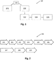
- FIG. 11 shows a schematic representation of the system 100 for casting a component 105 by means of an adjustable molding box 104 according to an exemplary embodiment of the present invention.
- a creation unit 101 is used to create a component model of the component 105 to be molded.
- a transmission unit 103 is used to transmit the component model via a data network to a determination unit 106.
- the determination unit 106 is used to determine a casting mold model based on the component model.
- the determination unit 106 is configured such that setting data for setting the adjustable molding box 104 can be created based on the mold model.
- a control unit 102 is with the Determination unit 106 coupled in such a way that the setting data can be provided to the control unit 102, the control unit 102 being configured such that the control unit 102 sets the molding box 104 based on the setting data with a casting mold which is indicative of a negative profile of the component 105 and that Component 105 can be cast by means of the set molding box 104.
- the creation unit 101 is spatially separated from the control unit 102 and / or the determination unit 106.
- the transmission unit 103 couples the creation unit 101 to the determination unit 106.
- the transmission unit 103 can be used to provide data transmission via the Internet.
- the creation unit 101 is, for example, a computing unit which can be operated by a user and on which the component model of the component to be formed can be created.
- a CAD system with which the component model can be constructed is installed on the creation unit 101.
- various boundary conditions such as length, width and height can be taken into account.
- the determination unit 106 is coupled to the transmission unit 103 and also to the control unit 102 and the adjustable mold box 104, so that the mold is set in the mold box 104 by the control unit 102 by means of the generated mold model. Subsequently, the component 105 can be cast by means of the casting mold in a casting process.
- the component model can thus be created remotely from the determination unit 106 or the control unit 102 by means of the creation unit 101 and processed at the remote determination unit 106 or control unit 102.
- the adjustable molding box 104 is arranged at the location of the control unit 102. In other words, a component model can be generated decentrally on a creation unit 101 and centrally with an adjustable molding box 104 the component 105 is cast.
- creation units 101 can be coupled to one and the same determination unit 106 or the control unit 102 via corresponding transmission units 103, so that a large number of different component models, which were created at the location of the creation unit 101, at one and the same location where the Molding box 104 is arranged, processed and cast by means of the molding box 104.
- Fig. 2 shows a schematic representation of a process diagram of a method for casting a component 105 by means of an adjustable molding box 104 according to an exemplary embodiment of the present invention.
- the individual method steps can run, for example, in the determination unit 106 or the control unit 102.
- the component model is created in the creation unit 101 and transmitted to the determination unit 106 by means of the transmission unit 103.
- the material selection 201 can be made in the determination unit 106. This can be made possible, for example, via an input mask which is operated by the user. For example, the user can operate the input mask via an Internet portal.
- step 202 the data of the component model is processed. Furthermore, an allowance for the component can be defined in step 203.
- the measurement definition 203 can also take place, for example, via the input mask in the determination unit 106. In particular, an allowance is used to determine a desired subsequent post-processing.
- the oversize can take place in different dimensions, for example in the z-direction.
- control commands for the adjustable molding box are sent by means of the control unit 102 based on the setting data of the Mold model created.
- the adjustable molding box 104 is set by means of the setting data of the casting mold model.
- the production time or delivery time can be determined in step 205. Furthermore, the determination unit 106 can determine the delivery time exactly based on the component parameters and based on the order quantity of components to be manufactured. The product data can then be combined and created in step 206 by means of the determination unit 106.
- the component is produced or cast by means of the now set molding box 104.
- the component 105 is then delivered in step 208 and billed in step 209.
Landscapes
- Engineering & Computer Science (AREA)
- Mechanical Engineering (AREA)
- Physics & Mathematics (AREA)
- Theoretical Computer Science (AREA)
- General Physics & Mathematics (AREA)
- Geometry (AREA)
- Evolutionary Computation (AREA)
- Mathematical Optimization (AREA)
- Pure & Applied Mathematics (AREA)
- Computer Hardware Design (AREA)
- Mathematical Analysis (AREA)
- General Engineering & Computer Science (AREA)
- Computational Mathematics (AREA)
- Moulds For Moulding Plastics Or The Like (AREA)
- Management, Administration, Business Operations System, And Electronic Commerce (AREA)
- Architecture (AREA)
- Software Systems (AREA)
Description
- Die vorliegende Erfindung betrifft ein System zum Gießen eines Bauteils mittels eines einstellbaren Formkastens sowie ein Verfahren zum Gießen eines Bauteils mittels eines einstellbaren Formkastens. Ferner betrifft die vorliegenden Erfindung ein Computer lesbare Speichermedium und ein Computerprogramm.
- Im Werkzeug,- Formen und Modellbau spielen sogenannte "HARD TOOLS" heutzutage immer noch eine große Rolle. Das Grundprinzip dieser Vorrichtungen bilden Blockaufbauten die das Negativ der Konturform des zu spannenden Bauteils wiedergeben.
- Diese vollen Blöcke können beispielweise aus Aluminium, Epoxy oder Ureol, bestehen. Je komplexer die Geometrie des dreidimensionalen Modells ist, desto größer ist der Materialverlust in Bezug auf den Rohblock. Bei 3-dimensionalen Modellen aus Ureol müssen diese Blöcke beispielsweise vorher aufwendig zusammengeklebt werden, da Ureolplatten nur in begrenzten Dicken erhältlich sind. Das Zusammenkleben der Ureolplatten ist ein zeitintensiver Arbeitsschritt. Alternativ besteht die Möglichkeit, das dreidimensionale Modell konturnahe zu gießen, sodass weniger Materialverlust und weniger Nachbearbeitungsschritte notwendig sind.
- Für den Gießprozess müssen allerdings individuelle Gussformen angefertigt werden, um verschieden geformte Rohblöcke herzustellen.
- Zum Einstellen individueller Gussformen werden beispielsweise einstellbare Formkästen bereitgestellt, welche individuell an verschiedene Formen angepasst werden können. Einstellbare Formkästen sind beispielsweise aus der
US 6,354 ,531 B1 ,WO 86/02877 A1 US 5,546,313 bekannt. DokumentUS 6354561 B1 offenbart ein System zum Gießen eines Bauteils mittels eines einstellbaren Formkastens, das System aufweisend: eine Erstelleinheit zum Erstellen eines Bauteilmodells des zu formenden Bauteils, die Bestimmungseinheit zum Bestimmen eines Gussformmodells basierend auf dem Bauteilmodell,wobei die Bestimmungseinheit derart konfiguriert ist, dass Einstellungsdaten zum Einstellen des einstellbaren Formkastens basierend auf dem Gussformmodell erstellbar sind, wobei die Bestimmungseinheit derart konfiguriert ist, dass ein Aufmaß zum Festlegen einer späteren Nachbearbeitung des zu gießenden Bauteils einstellbar ist, eine Steuereinheit, welche mit der Bestimmungseinheit derart gekoppelt ist, dass der Steuereinheit die Einstellungsdaten bereitstellbar sind, und den einstellbaren Formkasten, welcher die einstellbare Gussform aufweist, die indikativ für ein Negativprofil des Bauteils ist, wobei die Gussform ausgebildet ist, dass das Bauteil mittels des eingestellten Formkastens gießbar ist, wobei die Steuereinheit derart konfiguriert ist, dass die Steuereinheit den Formkasten basierend auf den Einstellungsdaten mit einer Gussform, welche indikativ für ein Negativprofil des Bauteils ist, einstellt und das Bauteil mittels des eingestellten Formkastens gießbar ist, wobei die Erstelleinheit räumlich von der Steuereinheit getrennt ist. - Es ist eine Aufgabe der vorliegenden Erfindung, schnell und kostengünstig individuelle Rohblöcke für den Werkzeug,- Formen und Modellbau herzustellen und bereitzustellen.
- Diese Aufgabe wird mit einem System zum Gießen eines Bauteils mittels eines einstellbaren Formkastens und mittels eines Verfahrens zum Gießen eines Bauteils mittels eines einstellbaren gemäß den unabhängigen Ansprüchen gelöst.
- Gemäß eines ersten Aspekts der vorliegenden Erfindung wird ein System zum Gießen eines Bauteils mittels eines einstellbaren Formkastens beschrieben. Das System weist eine Erstelleinheit zum Erstellen eines Bauteilmodells des zu formenden Bauteils, eine Übermittlungseinheit zum Übermitteln des Bauteilmodells über ein Datennetzwerk zu einer Bestimmungseinheit und die Bestimmungseinheit zum Bestimmen eines Gussformmodells basierend auf dem Bauteilmodell auf. Die Übermittlungseinheit dient zum Übermitteln des Bauteilmodells über ein Datennetzwerk zu der Bestimmungseinheit. Die Bestimmungseinheit ist derart konfiguriert, dass Einstellungsdaten zum Einstellen des einstellbaren Formkastens basierend auf dem Gussformmodell erstellbar sind. Die Steuereinheit ist mit der Bestimmungseinheit derart gekoppelt, dass der Steuereinheit die Einstellungsdaten bereitstellbar sind, wobei die Steuereinheit derart konfiguriert ist, dass die Steuereinheit den Formkasten basierend auf den Einstellungsdaten mit einer Gussform, welche indikativ für ein Negativprofil des Bauteils ist, einstellt und das Bauteil mittels des eingestellten Formkastens gießbar ist.
- Gemäß eines ersten Aspekts der vorliegenden Erfindung wird ein Verfahren zum Gießen eines Bauteils mittels eines einstellbaren Formkastens beschrieben. Gemäß dem Verfahren wird ein Bauteilmodell eines zu formenden Bauteils erstellt. Das Bauteilmodell wird über ein Datennetzwerk zu einer Bestimmungseinheit übermittelt. Ein Gussformmodell wird basierend auf dem Bauteilmodell mittels der Bestimmungseinheit erstellt. Ferner werden Einstellungsdaten zum Einstellen des einstellbaren Formkastens basierend auf dem Gussformmodell erstellt, sodass der Formkasten mit einer Gussform, welche indikativ für ein Negativprofil des Bauteils ist, eingestellt wird und das Bauteil mittels des eingestellten Formkastens gegossen werden kann.
- Das Bauteil ist beispielsweise ein dreidimensionales Objekt wie es beispielsweise einen Werkzeug-, Form oder Modellblock darstellen kann. Bei dem Bauteil handelte es sich um ein gegossenes Bauteil, welches zum Beispiel aus Ureol oder Aluminium gegossen werden kann.
- Der einstellbare Formkasten bildet eine einstellbare Gussform aus. Der einstellbare Formkasten weist beispielsweise einstellbare Formelemente auf, welche derart relativ zueinander verschoben werden können, dass eine gewünschte Gussform, welche mittels des Gussformmodells vorgegeben wird und insbesondere einer Negativform des Bauteils entspricht, eingestellt ist (vgl. Nadelbett). Die einzelnen Formelemente können beispielsweise von der Steuereinheit steuerbar sein, um basierend darauf eine gewünschte Gussform einstellen. Nach Einstellens der Gussform kann diese beispielsweise mit einem Gussmaterial befüllt werden. Nach dem Aushärten des Materials kann das fertige ausgehärtet Bauteil aus der Gussform entnommen werden.
- Die einstellbaren Formelemente können beispielsweise dicht gepackt , z.B. aneinander anliegend, vorliegen und z.B. entsprechende Enden der einstellbaren Formelemente, wie beispielsweise Stellstäbe, die Gussform ausbilden. Die einstellbaren Formelemente sind beispielsweise in einem ersten Satz und in einem zweiten Satz ausgebildet, wobei beide Sätze gegenüberliegen. Zwischen den jeweiligen Sätzen an Einstellelementen wird ein Hohlraum gebildet, in welchen die Gussmasse eingefüllt wird. Die Einstellelemente in jedem Satz können einzelnen zueinander verschoben werden, sodass die Enden der jeweiligen Einstellelemente eine gewünschte Form des Hohlraums und somit eine gewünschte Form des auszugießenden Bauteils (d.h. die Gussform, welche indikativ für ein Negativprofil des Bauteils ist) bilden. Die Einstellelemente liegen beispielsweise aufeinander auf, sodass aufgrund der Schwerkraft ein fester Verbund der Einstellelemente zueinander erzeugbar ist. Die Einstellelement können somit aufeinandergelegt werden und benötigen keine komplexen Verbindungsmechanik. Beispielsweise liegen die einzelnen Einstellelemente vertikal übereinander und können jeweils horizontal einzeln oder paarweise zueinander verschoben werden. Die jeweiligen Sätze an Einstellelementen stehen sich beispielsweise horizontal gegenüber und können somit in horizontaler Richtung zueinander oder voneinander fort verschoben werden.
- Im Rahmen dieser Anmeldung wird unter dem Begriff "Übertragungseinheit" eine automatisierte und netzwerkbasierte Anordnung aus miteinander kommunizierfähig gekoppelten oder koppelbaren Entitäten verstanden, die Zwischenschaltung einer Bedienperson Daten, z.B. des Bauteilmodells, über das Datennetzwerk übertragen kann. Die Entitäten sind örtlich getrennte Netzwerkelemente, wie beispielsweise Router oder Modems, welche beispielsweise über das Internet als Datennetzwerk kommunikationsfähig miteinander verbunden sind. Die Erstelleinheit kann an eine erste Entität und die Steuereinheit an eine zweite Entität gekoppelt werden.
- Die Erstelleinheit ist beispielsweise eine Recheneinheit, welche durch einen Benutzer bedienbar ist und auf welcher das Bauteilmodell des zu formenden Bauteils erstellt werden kann. Auf der Erstelleinheit kann beispielsweise ein CAD-System installiert sein, mit welchen das Bauteilmodell konstruiert werden kann. Dabei können beispielsweise verschiedene Randbedingungen wie Länge, Breite und Höhe berücksichtigt werden. Das Bauteilmodell kann beispielsweise einen Datensatz aufweisen, in welchen Informationen bezüglich der geometrischen Ausstattung, der Materialausgestaltung und/oder der andere Parameter, beispielsweise Temperaturbeständigkeitsparameter oder Säurebeständigkeitsparameter, des zu Formen Bauteils vorliegen.
- Der Datensatz kann beispielsweise mittels eines CAD-Programms (Computer Aided Design) auf der Erstelleinheit erzeugt werden. Der Datensatz bildet somit eine dreidimensionale Abbildung des Bauteilmodells.
- Im Rahmen dieser Anmeldung wird unter dem Begriff "Bestimmungseinheit" insbesondere eine Einrichtung mit Prozessorressource verstanden, die zum - insbesondere programmtechnischen - Verarbeiten der bereitgestellten Daten des Bauteilmodells konfiguriert ist und die ferner zum Erstellen des Gussformmodells basierend auf dem Bauteilmodell konfiguriert ist. Während dieser Verarbeitung kann die Prozessorressource mit einer Datenspeicherressource der Bestimmungseinheit unidirektional oder vorzugsweise bidirektional kommunizierfähig gekoppelt sein, um von dort Daten einzulesen und/oder auf dieser Daten zu speichern. Die Bestimmungseinheit kann zum Beispiel als ein Computer bzw. Prozessor oder als Mehrzahl von zusammenwirkenden Computern oder Prozessoren (die räumlich beieinander liegen oder voneinander räumlich getrennt sein können) ausgebildet sein.
- Auf der Erstelleinheit kann beispielsweise ein CAD-System installiert sein, mit welchem das Bauteilmodell konstruiert werden kann. Dabei können beispielsweise u.a. verschiedene Randbedingungen wie Länge, Breite und Höhe berücksichtigt werden. Mit anderen Worten wird auf der Erstelleinheit ein Modell des Bauteils mit den gewünschten geometrischen Ausgestaltungen erstellt. Der Datensatz, insbesondere die CAD Daten, werden anschließend mittels der Übermittlungseinheit an die Bestimmungseinheit übermittelt.
- Ferner erzeugt die Bestimmungseinheit CAM-Daten als Einstellungsdaten zum Einstellen des einstellbaren Formkastens basierend auf dem Gussformmodell. Die Bestimmungseinheit liest beispielsweise die von der Erstelleinheit übermittelten CAD Daten umfassend die Geometriedaten für Rohteil, Fertigteil und Aufspannvorrichtung ein. Falls es erforderlich ist, dass die Geometrie verändert oder neue Geometrie (Modelle) erstellt werden müssen, werden entsprechend neue CAM-Daten generiert. Der Werkstoff und die Einstellung des Formkastens werden bestimmt. Die CAM-Daten berücksichtigen die Randbedingungen und geeignete Verfahrbewegungen und Schnittwerte des Formkastens bzw. der einstellbaren Formelemente. Zum Beispiel werden die im CAM definierten Operationen zusammen mit allen Parametern als "Quellcode" im CAM-Format gespeichert.
- Die Bestimmungseinheit, die Steuereinheit, die Übermittlungseinheit und/oder die Erstelleinheit sind zum bidirektionale Datenaustausch ausgebildet und vernetzt. Entsprechend kann beispielsweise die Bestimmungseinheit CAD-Daten des Bauteils erhalten und die daraus generierte CAM-Daten zurück an die Erstelleinheit übermitteln.
- Ferner kann aufgrund der bidirektionalen Datenübertragung von der Erstelleinheit zu jedem beliebigen Zeitpunkt eine Statusanfrage an die Bestimmungseinheit und/oder die Steuereinheit übermittelt werden, worauf die Bestimmungseinheit den Status (d.h. den Prozessfortschritt) der Bestimmung des Gussformmodells und/oder die Steuereinheit den Satus (d.h. den Prozessfortschritt) der Einstellung des Formkastens und/oder den Fortschritt des Gießprozesses an die Erstelleinheit zurückübermittelt. Somit kann permanent zu einem gewünschten Zeitpunkt der Prozessfortschritt abgefragt werden.
Die Bestimmungseinheit kann ferner z.B. Volumendaten der Gussform und/oder des Bauteils und auch Daten betreffend Lieferzeit des Bauteils und Kosten der Herstellung des Bauteils bestimmen und an die Einstelleinheit übertragen. - Die Steuereinheit wird ebenfalls insbesondere eine Einrichtung mit Prozessorressource verstanden, die zum - insbesondere programmtechnischen - Verarbeiten der bereitgestellten Daten des Gussformmodells konfiguriert ist und die ferner zum Steuern des Formkastens konfiguriert ist. Während dieser Verarbeitung kann die Prozessorressource mit einer Datenspeicherressource der Steuereinheit unidirektional oder vorzugsweise bidirektional kommunizierfähig gekoppelt sein, um von dort Daten einzulesen und/oder auf dieser Daten zu speichern. Die Steuereinheit kann zum Beispiel als ein Computer bzw. Prozessor oder als Mehrzahl von zusammenwirkenden Computern oder Prozessoren (die räumlich beieinander liegen oder voneinander räumlich getrennt sein können) ausgebildet sein.
- Die Steuereinheit ist konfiguriert, basierend auf dem Gussformmodel maschinenlesbare Befehle zu generieren, um damit den Formenkasten einzustellen. Die Steuereinheit ist mit dem einstellbaren Formkasten gekoppelt, sodass das erzeugte Gussformmodell die Gussform in den Formkasten vorgibt. Anschließend kann mittels der Gussform in einem Gießprozess das Bauteil gegossen werden.
- Mit der vorliegenden Erfindung kann die Erstelleinheit räumlich getrennt von der Bestimmungseinheit und/oder der Steuereinheit angeordnet werden und mittels der Übermittlungseinheit gekoppelt werden. Somit kann entfernt von der Bestimmungseinheit ein Bauteilmodell erstellt werden und an der entfernten Bestimmungseinheit und Steuereinheit verarbeitet werden. Der einstellbare Formkasten ist am Ort der Steuereinheit angeordnet. Mit anderen Worten kann somit dezentral an einer Erstelleinheit ein Bauteilmodell erzeugt werden und zentral mit einem Formkasten das Bauteil gegossen werden. Insbesondere können mehrere Erstelleinheiten mit ein und derselben Bestimmungseinheit und/oder Steuereinheit über entsprechende Übermittlungseinheiten gekoppelt werden, sodass eine Vielzahl von verschiedenen Bauteilmodellen, welche am Ort der Erstelleinheit erstellt wurden, an ein- und demselben Ort, an welchem der Formkasten angeordnet ist, verarbeitet werden und mittels des Formkastens gegossen werden.
- Somit können gerade beim Werkzeug,- Formen oder Modellbau die erforderlichen Kosten zur Erstellung eines Rohblockes reduziert werden, da es nicht länger notwendig ist, am Ort der Erstelleinheit einen entsprechenden Formkasten bereitzustellen. Mit der vorliegenden Erfindung kann ein- und derselbe Formkasten verschiedene Bauteilmodelle aus verschiedenen Erstelleinheiten verarbeiten. Somit kann der Hardwareeinsatz und entsprechend die Kosten deutlich reduziert werden, da statt einer Vielzahl von Formkästen lediglich ein Formkasten ausreichen kann, um die Vielzahl von Bauteilmodell aus verschiedensten Erstelleinheit zu verarbeiten.
- Gemäß einer weiteren beispielhaften Ausführungsform ist die Bestimmungseinheit derart konfiguriert, dass ein Material des zu gießenden Bauteils einstellbar ist. Der Benutzer kann beispielsweise direkt auf der Erstelleinheit oder mittels einer Eingabemaske der Steuereinheit Materialparameter eingeben. Dabei kann der Benutzer via des Datennetzwerks die Eingabemaske der Steuereinheit bedienen.
- Erfindungsgemäß ist die Bestimmungseinheit derart konfiguriert, dass ein Aufmaß des zu gießenden Bauteils einstellbar ist. Insbesondere dient ein Aufmaß dazu, eine gewünschte spätere Nachbearbeitung des Bauteils festzulegen. Das Aufmaß kann in verschiedene Dimensionen, beispielsweise in z-Richtung erfolgen.
- Die Bestimmungseinheit kann basierend auf den CAD-Daten des Bauteils selbsttätig bestimmte Aufmaßgrößen bestimmen. Ferner kann bei einer bidirektionalen Datenübertragung zwischen der Bestimmungseinheit das von der Bestimmungseinheit bestimmte Aufmaß an die Erstelleinheit übermittelt werden. Ferner kann ein Aufmaß an der Erstelleinheit vorgegebenen und an die Bestimmungseinheit übermittelt werden.
- Erfindungsgemäß ist die Erstelleinheit räumlich von der Bestimmungseinheit und/oder Steuereinheit getrennt.
- Erfindungsgemäß weist das System ferner den einstellbaren Formkasten auf, welcher die einstellbare Gussform aufweist, die indikativ für ein Negativprofil des Bauteils ist. Die Gussform ist ausgebildet, dass das Bauteil mittels des eingestellten Formkastens gießbar ist.
- Gemäß einer weiteren beispielhaften Ausführungsform ist die Steuereinheit derart konfiguriert ist, dass eine Fertigungszeit und eine Lieferzeit des gegossenen Bauteils zu einer Lieferadresse bestimmbar bzw. auslesbar sind. An der Lieferadresse liegt in einer beispielhaften Ausführungsform auch die Erstelleinheit vor. In einer weiteren beispielhaften Ausführungsform liegt die Erstelleinheit räumlich getrennt von der Lieferadresse vor.
- Gemäß eines weiteren nicht separat beanspruchten Aspekts der vorliegenden Erfindung wird ein computerlesbares Speichermedium beschrieben, in dem ein Programm zum Gießen eines Bauteils mittels eines einstellbaren Formkastens gespeichert ist. Das computerlesbare Speichermedium weist, wenn es von einem Prozessor (z.B. der Bestimmungseinheit) ausgeführt wird, folgende Verfahrensschritte auf:
- Bestimmen eines Gussformmodells basierend auf einem Bauteilmodell wobei das Bauteilmodells indikativ zu dem zu formende Bauteils ist und das Bauteilmodell über ein Datennetzwerk übermittelbar ist,
- Bestimmen von Einstellungsdaten zum Einstellen des einstellbaren Formkastens basierend auf dem Gussformmodell, sodass der Formkasten mit einer Gussform, welche indikativ für ein Negativprofil des Bauteils ist, eingestellt wird und das Bauteil mittels des eingestellten Formkastens gießbar ist.
- Gemäß eines weiteren nicht separat beanspruchten Aspekts der vorliegenden Erfindung wird ein Computerprogramm zum Gießen eines Bauteils mittels eines einstellbaren Formkastens beschreiben. Das Computerprogramm ist, wenn es von einem Prozessor ausgeführt wird, zum Durchführen des oben beschriebenen Verfahrens zum Gießen eines Bauteils mittels eines einstellbaren Formkastens eingerichtet.
- Das Computerprogramm kann als computerlesbarer Anweisungscode in jeder geeigneten Programmiersprache wie beispielsweise in JAVA, C++, .net, C# etc. implementiert sein. Das Computerprogramm kann auf einem computerlesbaren Speichermedium (CD-ROM, DVD, Blu-ray Disk, Solid-Disk, Wechsellaufwerk, flüchtiger oder nicht-flüchtiger Speicher, eingebauter Speicher/Prozessor etc.) abgespeichert sein. Der Anweisungscode kann einen Computer oder andere programmierbare Geräte, wie beispielsweise die Erstelleinheit und/oder die Steuereinheit, dass die gewünschten Funktionen ausgeführt werden. Ferner kann das Computerprogramm in dem Datennetzwerk, wie beispielsweise dem Internet (z.B. Website basiert, oder Cloud basiert), bereitgestellt werden, von dem es bei Bedarf von einem Nutzer bedient oder heruntergeladen werden kann.
- Die Erfindung kann sowohl mittels eines Computerprogramms, d.h. einer Software, als auch mittels einer oder mehrerer spezieller elektrischer Schaltungen, d.h. in Hardware oder in beliebig hybrider Form, d.h. mittels Software-Komponenten und Hardware-Komponenten, realisiert werden.
- Es wird darauf hingewiesen, dass die hier beschriebenen Ausführungsformen lediglich eine beschränkte Auswahl an möglichen Ausführungsvarianten der Erfindung darstellen. So ist es möglich, die Merkmale einzelner Ausführungsformen in geeigneter Weise miteinander zu kombinieren, so dass für den Fachmann mit den hier expliziten Ausführungsvarianten eine Vielzahl von verschiedenen Ausführungsformen als offensichtlich offenbart anzusehen sind. Insbesondere sind einige Ausführungsformen der Erfindung mit Vorrichtungsansprüchen und andere Ausführungsformen der Erfindung mit Verfahrensansprüchen beschrieben. Dem Fachmann wird jedoch bei der Lektüre dieser Anmeldung sofort klar werden, dass, sofern nicht explizit anders angegeben, zusätzlich zu einer Kombination von Merkmalen, die zu einem Typ von Erfindungsgegenstand gehören, auch eine beliebige Kombination von Merkmalen möglich ist, die zu unterschiedlichen Typen von Erfindungsgegenständen gehören.
- Im Folgenden werden zur weiteren Erläuterung und zum besseren Verständnis der vorliegenden Erfindung Ausführungsbeispiele unter Bezugnahme auf die beigefügten Zeichnungen näher beschrieben. Es zeigen:
-
Fig. 1 zeigt eine schematische Darstellung des Systems zum Gießen eines Bauteils mittels eines einstellbaren Formkastens gemäß einer beispielhaften Ausführungsform der vorliegenden Erfindung, und -
Fig. 2 zeigt eine schematische Darstellung eines Prozessschaubilds eines Verfahrens zum Gießen eines Bauteils mittels eines einstellbaren Formkastens gemäß einer beispielhaften Ausführungsform der vorliegenden Erfindung. - Gleiche oder ähnliche Komponenten in unterschiedlichen Figuren sind mit gleichen Bezugsziffern versehen. Die Darstellungen in den Figuren sind schematisch.
-
Fig. 1 zeigt eine schematische Darstellung des Systems 100 zum Gießen eines Bauteils 105 mittels eines einstellbaren Formkastens 104 gemäß einer beispielhaften Ausführungsform der vorliegenden Erfindung. Eine Erstelleinheit 101 dient zum Erstellen eines Bauteilmodells des zu formenden Bauteils 105. Eine Übermittlungseinheit 103 dient zum Übermitteln des Bauteilmodells über ein Datennetzwerk zu einer Bestimmungseinheit 106. Die Bestimmungseinheit 106 dient zum Bestimmen eines Gussformmodells basierend auf dem Bauteilmodell. Die Bestimmungseinheit 106 ist derart konfiguriert, dass Einstellungsdaten zum Einstellen des einstellbaren Formkastens 104 basierend auf dem Gussformmodell erstellbar sind. Eine Steuereinheit 102 ist mit der Bestimmungseinheit 106 derart gekoppelt, dass der Steuereinheit 102 die Einstellungsdaten bereitstellbar sind, wobei die Steuereinheit 102 derart konfiguriert ist, dass die Steuereinheit 102 den Formkasten 104 basierend auf den Einstellungsdaten mit einer Gussform, welche indikativ für ein Negativprofil des Bauteils 105 ist, einstellt und das Bauteil 105 mittels des eingestellten Formkastens 104 gießbar ist. - Die Erstelleinheit 101 ist dabei räumlich getrennt von der Steuereinheit 102 und/oder der Bestimmungseinheit 106 angeordnet. Die Übermittlungseinheit 103 koppelt die Erstelleinheit 101 mit der Bestimmungseinheit 106. Beispielsweise kann mittels der Übermittlungseinheit 103 eine Datenübermittlung via des Internets bereitgestellt werden.
- Die Erstelleinheit 101 ist beispielsweise eine Recheneinheit, welche durch einen Benutzer bedienbar ist und auf welcher das Bauteilmodell des zu formenden Bauteils erstellt werden kann. Auf der Erstelleinheit 101 ist beispielsweise ein CAD-System installiert, mit welchen das Bauteilmodell konstruiert werden kann. Dabei können beispielsweise verschiedene Randbedingungen wie Länge, Breite und Höhe berücksichtigt werden.
- Die Bestimmungseinheit 106 ist mit der Übermittlungseinheit 103 und ferner mit der Steuereinheit 102 und dem einstellbaren Formkasten 104 gekoppelt, sodass mittels des erzeugten Gussformmodells die Gussform in den Formkasten 104 von der Steuereinheit 102 eingestellt wird. Anschließend kann mittels der Gussform in einem Gießprozess das Bauteil 105 gegossen werden. Das Bauteilmodell kann somit entfernt von der Bestimmungseinheit 106 bzw. der Steuereinheit 102 mittels der Erstelleinheit 101 erstellt werden und an der entfernten Bestimmungseinheit 106 bzw. Steuereinheit 102 verarbeitet werden. Der einstellbare Formkasten 104 ist am Ort der Steuereinheit 102 angeordnet. Mit anderen Worten kann dezentral an einer Erstelleinheit 101 ein Bauteilmodell erzeugt werden und zentral mit einem einstellbaren Formkasten 104 das Bauteil 105 gegossen werden. Insbesondere können mehrere Erstelleinheiten 101 mit ein- und derselben Bestimmungseinheit 106 bzw. der Steuereinheit 102 über entsprechende Übermittlungseinheiten 103 gekoppelt werden, sodass eine Vielzahl von verschiedenen Bauteilmodellen, welche am Ort der Erstelleinheit 101 erstellt wurden, an ein- und demselben Ort, an welchem der Formkasten 104 angeordnet ist, verarbeitet werden und mittels des Formkastens 104 gegossen werden.
-
Fig. 2 zeigt eine schematische Darstellung eines Prozessschaubilds eines Verfahrens zum Gießen eines Bauteils 105 mittels eines einstellbaren Formkastens 104 gemäß einer beispielhaften Ausführungsform der vorliegenden Erfindung. Die einzelnen Verfahrensschritte können beispielsweise in der Bestimmungseinheit 106 bzw. der Steuereinheit 102 ablaufen. Vorab wird das Bauteilmodell in der Erstelleinheit 101 erstellt und mittels der Übermittlungseinheit 103 an die Bestimmungseinheit 106 übermittelt. - In der Bestimmungseinheit 106 kann beispielsweise in einem nächsten Schritt die Materialauswahl 201 getroffen werden. Dies kann beispielsweise über eine Eingabemaske ermöglicht werden, welche durch den Benutzer bedient wird. Beispielsweise kann der Benutzer über ein Internetportal die Eingabemaske bedienen.
- Anschließend wird in Schritt 202 die Daten des Bauteilmodells verarbeitet. Ferner kann in Schritt 203 ein Aufmaß des Bauteils definiert werden. Die Aufmaßdefinition 203 kann ebenfalls beispielsweise über die Eingabemaske in der Bestimmungseinheit 106 erfolgen. Insbesondere dient ein Aufmaß dazu, eine gewünschte spätere Nachbearbeitung festzulegen. Das Aufmaß kann in verschiedene Dimensionen, beispielsweise in z-Richtung erfolgen. In Verfahrensschritt 204 werden Steuerbefehle für den einstellbaren Formkasten mittels der Steuereinheit 102 basierend auf den Einstellungsdaten des Gussformmodells erstellt. Mittels der Einstellungsdaten des Gussformmodells wird der einstellbare Formkasten 104 eingestellt.
- Ferner kann basierend auf den eingegebenen Parametern, wie beispielsweise der geometrischen Abmessungen des Bauteils oder der Materialzusammensetzung, die Fertigungszeit bzw. Lieferzeit in Schritt 205 bestimmt werden. Ferner kann die Bestimmungseinheit 106 basierend auf den Bauteilparametern und basierend auf der Auftragsmenge an zu fertigenden Bauteilen die Lieferzeit exakt bestimmen. Anschließend können mittels der Bestimmungseinheit 106 die Produktdaten in Schritt 206 zusammengefasst und erstellt werden.
- Mittels des nun eingestellten Formkastens 104 wird das Bauteil produziert bzw. gegossen. Anschließend wird das Bauteil 105 in Schritt 208 geliefert und in Schritt 209 abgerechnet.
- Ergänzend ist darauf hinzuweisen, dass "umfassend" keine anderen Elemente oder Schritte ausschließt und "eine" oder "ein" keine Vielzahl ausschließt. Ferner sei darauf hingewiesen, dass Merkmale oder Schritte, die mit Verweis auf eines der obigen Ausführungsbeispiele beschrieben worden ist, auch in Kombination mit anderen Merkmalen oder Schritten anderer oben beschriebener Ausführungsbeispiele verwendet werden können. Bezugszeichen in den Ansprüchen sind nicht als Einschränkung anzusehen.
-
- 100
- System
- 101
- Erstelleinheit
- 102
- Steuereinheit
- 103
- Übermittlungseinheit
- 104
- Formkasten
- 105
- Bauteil
- 106
- Bestimmungseinheit
- 201
- Materialauswahl
- 202
- Datenverarbeitung des Bauteilmodells
- 203
- Aufmaßdefinition
- 204
- Steuerdaten für Formkasten
- 205
- Bestimmung Fertigungszeit/Lieferzeit
- 206
- Produktdaten erstellen
- 207
- Produktion/Gießen des Bauteils
- 208
- Lieferung des Bauteils
- 209
- Abrechnung
Claims (4)
- System (100) zum Gießen eines Bauteils (105) mittels eines einstellbaren Formkastens (104), das System (100) aufweisend:eine Erstelleinheit (101) zum Erstellen eines Bauteilmodells des zu formenden Bauteils (105),eine Übermittlungseinheit (103) zum Übermitteln des Bauteilmodells über ein Datennetzwerk zu einer Bestimmungseinheit (106),die Bestimmungseinheit (106) zum Bestimmen eines Gussformmodells basierend auf dem Bauteilmodell,wobei die Bestimmungseinheit (106) derart konfiguriert ist, dass Einstellungsdaten zum Einstellen des einstellbaren Formkastens (104) basierend auf dem Gussformmodell erstellbar sind,
wobei die Bestimmungseinheit (106) derart konfiguriert ist, dass ein Aufmaß zum Festlegen einer späteren Nachbearbeitung des zu gießenden Bauteils (105) einstellbar ist,eine Steuereinheit (102), welche mit der Bestimmungseinheit (106) derart gekoppelt ist, dass der Steuereinheit (102) die Einstellungsdaten bereitstellbar sind, undden einstellbaren Formkasten (104), welcher die einstellbare Gussform aufweist, die indikativ für ein Negativprofil des Bauteils (105) ist,wobei die Gussform ausgebildet ist, dass das Bauteil (105) mittels des eingestellten Formkastens (104) gießbar ist,
wobei die Steuereinheit (102) derart konfiguriert ist, dass die Steuereinheit (102) den Formkasten (104) basierend auf den Einstellungsdaten mit einer Gussform, welche indikativ für ein Negativprofil des Bauteils (105) ist, einstellt und das Bauteil (105) mittels des eingestellten Formkastens (104) gießbar ist,
wobei die Erstelleinheit (101) räumlich von der Steuereinheit (102) getrennt ist,
wobei die Übermittlungseinheit (103) die Erstelleinheit (101) mit der Bestimmungseinheit (106) zum bidirektionalen Datenaustausch derart koppelt,
dass von der Erstelleinheit (101) zu einem beliebigen Zeitpunkt eine Statusanfrage an die Bestimmungseinheit (106) und/oder die Steuereinheit (102) übermittelbar ist, worauf von der Bestimmungseinheit (106) der Status der Bestimmung des Gussformmodells und/oder von der Steuereinheit (102) der Status der Einstellung des Formkastens (104) und/oder der Fortschritt des Gießprozesses an die Erstelleinheit (101) zurückübermittelbar ist. - System (100) gemäß Anspruch 1,
wobei die Bestimmungseinheit (106) derart konfiguriert ist, dass ein Material des zu gießenden Bauteils (105) einstellbar ist. - System (100) gemäß Anspruch 1 oder 2,
wobei die Bestimmungseinheit (106) derart konfiguriert ist, dass eine Fertigungszeit und eine Lieferzeit des gegossenen Bauteils (105) zu einer Lieferadresse bestimmbar sind. - Verfahren zum Gießen eines Bauteils (105) mittels eines einstellbaren Formkastens (104) mit einem System gemäß einem der Ansprüche 1 bis 3.
Applications Claiming Priority (2)
| Application Number | Priority Date | Filing Date | Title |
|---|---|---|---|
| DE102015106577.0A DE102015106577A1 (de) | 2015-04-29 | 2015-04-29 | Prozess zum Gießen von formangepassten Rohblöcken mittels CNC-einstellbaren Formkästen |
| PCT/EP2016/059554 WO2016174167A1 (de) | 2015-04-29 | 2016-04-28 | System und verfahren zum giessen eines bauteils sowie computerlesbares speichermedium mit einem programm zum giessen eines bauteils |
Publications (2)
| Publication Number | Publication Date |
|---|---|
| EP3288740A1 EP3288740A1 (de) | 2018-03-07 |
| EP3288740B1 true EP3288740B1 (de) | 2021-01-06 |
Family
ID=56024234
Family Applications (1)
| Application Number | Title | Priority Date | Filing Date |
|---|---|---|---|
| EP16723673.6A Active EP3288740B1 (de) | 2015-04-29 | 2016-04-28 | System und verfahren zum giessen eines bauteils |
Country Status (6)
| Country | Link |
|---|---|
| US (1) | US11130260B2 (de) |
| EP (1) | EP3288740B1 (de) |
| CA (1) | CA2984189C (de) |
| DE (1) | DE102015106577A1 (de) |
| ES (1) | ES2855121T3 (de) |
| WO (1) | WO2016174167A1 (de) |
Families Citing this family (2)
| Publication number | Priority date | Publication date | Assignee | Title |
|---|---|---|---|---|
| JP6922854B2 (ja) * | 2018-06-15 | 2021-08-18 | 新東工業株式会社 | 鋳造設備及び鋳造方法 |
| US11341409B2 (en) * | 2018-11-28 | 2022-05-24 | Servicenow Canada Inc. | Systems and methods for error reduction in materials casting |
Citations (4)
| Publication number | Priority date | Publication date | Assignee | Title |
|---|---|---|---|---|
| US5330343A (en) * | 1992-11-10 | 1994-07-19 | Autocontrole Inc. | Variable-shape mold |
| US6354561B1 (en) * | 1996-07-11 | 2002-03-12 | Otmar Fahrion | Adjustable casting mould, and device for adjusting the mould surface thereof |
| US20080302500A1 (en) * | 2007-06-07 | 2008-12-11 | The Boeing Company | Reusable mold forming tool |
| WO2011034434A1 (en) * | 2009-09-21 | 2011-03-24 | Sebastiaan Henri Alphons Boers | System for controlling a discrete die |
Family Cites Families (11)
| Publication number | Priority date | Publication date | Assignee | Title |
|---|---|---|---|---|
| US531A (en) | 1837-12-20 | Machine fob | ||
| US6354A (en) | 1849-04-17 | Cut nails from muntz s metal | ||
| EP0199720A1 (de) | 1984-11-05 | 1986-11-05 | Olavi MÄKINEN | Einstellbare giessform |
| US5546313A (en) | 1994-09-12 | 1996-08-13 | Masters; William E. | Method and apparatus for producing three-dimensional articles from a computer generated design |
| US5796620A (en) * | 1995-02-03 | 1998-08-18 | Cleveland Advanced Manufacturing Program | Computerized system for lost foam casting process using rapid tooling set-up |
| US6354531B1 (en) | 1998-02-19 | 2002-03-12 | Metso, Paper, Inc. | Apparatus and method for continuously reeling a web material |
| US6116888A (en) | 1998-07-29 | 2000-09-12 | Owens-Brockway Plastic Products Inc. | Prototype mold for blow-molding hollow plastic containers and method of making same |
| US6836699B2 (en) * | 2001-12-27 | 2004-12-28 | The Protomold Company, Inc. | Automated quoting of molds and molded parts |
| US7019898B2 (en) * | 2002-01-09 | 2006-03-28 | Derrick John Page | Flexible reconfigurable surface |
| WO2009120359A2 (en) | 2008-03-27 | 2009-10-01 | Iterations, Inc. | Three dimensional variable forming apparatus and methods of use thereof |
| EP2565018B1 (de) | 2011-08-31 | 2020-12-30 | Fit Ag | Datenmodell zur Beschreibung eines mit Hilfe eines Schichtaufbauverfahrens herzustellenden Bauteils |
-
2015
- 2015-04-29 DE DE102015106577.0A patent/DE102015106577A1/de not_active Ceased
-
2016
- 2016-04-28 EP EP16723673.6A patent/EP3288740B1/de active Active
- 2016-04-28 WO PCT/EP2016/059554 patent/WO2016174167A1/de not_active Ceased
- 2016-04-28 US US15/570,250 patent/US11130260B2/en active Active
- 2016-04-28 ES ES16723673T patent/ES2855121T3/es active Active
- 2016-04-28 CA CA2984189A patent/CA2984189C/en active Active
Patent Citations (4)
| Publication number | Priority date | Publication date | Assignee | Title |
|---|---|---|---|---|
| US5330343A (en) * | 1992-11-10 | 1994-07-19 | Autocontrole Inc. | Variable-shape mold |
| US6354561B1 (en) * | 1996-07-11 | 2002-03-12 | Otmar Fahrion | Adjustable casting mould, and device for adjusting the mould surface thereof |
| US20080302500A1 (en) * | 2007-06-07 | 2008-12-11 | The Boeing Company | Reusable mold forming tool |
| WO2011034434A1 (en) * | 2009-09-21 | 2011-03-24 | Sebastiaan Henri Alphons Boers | System for controlling a discrete die |
Also Published As
| Publication number | Publication date |
|---|---|
| CA2984189C (en) | 2023-10-31 |
| CA2984189A1 (en) | 2016-11-03 |
| ES2855121T3 (es) | 2021-09-23 |
| WO2016174167A1 (de) | 2016-11-03 |
| US11130260B2 (en) | 2021-09-28 |
| DE102015106577A1 (de) | 2016-11-03 |
| EP3288740A1 (de) | 2018-03-07 |
| US20180126601A1 (en) | 2018-05-10 |
Similar Documents
| Publication | Publication Date | Title |
|---|---|---|
| EP3475018B1 (de) | Verfahren zum austragen von füllmaterial aus einem in einem bauteil vorhandenen hohlraum und apparat zur durchführung dieses verfahrens | |
| DE112020002059T5 (de) | Topologieoptimierung einer struktur mit mehreren zielen | |
| DE112017006561T5 (de) | Thermische-verformungsgrösse-berechnungsvorrichtung, dreidimensionales laminierungssystem, dreidimensionales laminierungsverfahren, und programm | |
| EP2953576B1 (de) | Verfahren zur herstellung eines verzugsfreien dentalmodells und solchermassen hergestelltes dentalmodell | |
| WO2016091629A1 (de) | Verfahren zum herstellen eines kompressorlaufrads | |
| DE112017004424T5 (de) | Befehlswerterzeugungsvorrichtung | |
| WO2017098003A2 (de) | Verfahren und vorrichtung zur prüfung eines eingangsdatensatzes einer generativen schichtbauvorrichtung | |
| EP3288740B1 (de) | System und verfahren zum giessen eines bauteils | |
| EP3376412A1 (de) | Verfahren zum erstellen eines geometriedatensatzes bzw. eines ablaufplans für die additive herstellung eines werkstücks und computerprogrammprodukt sowie datennetzwerk zur durchführung dieses verfahrens | |
| DE19649428B4 (de) | Verfahren und Vorrichtung zur Herstellung einer Form | |
| DE202017100135U1 (de) | Refinerscheibensegment | |
| DE102015214750A1 (de) | Verfahren und Vorrichtung zur Form- und Topologieoptimierung eines Gussbauteils | |
| DE102018003185A1 (de) | Verfahren und Vorrichtung zum Herstellen eines Bauteils | |
| DE102017122880A1 (de) | Metallhülse zur Reduzierung von Verformungen bei der additiven Herstellung | |
| EP3719736A1 (de) | Verfahren und vorrichtung für ein automatisches selektieren eines optimalen herstellungsablaufes | |
| DE10014744B4 (de) | Verfahren zur Herstellung von metallischen Hohlformen | |
| DE102010049334A1 (de) | Verfahren zur Herstellung eines Anlegeteils für ein Verbundgussteil und Verfahren zur Herstellung eines Verbundgussteils | |
| DE10156332B4 (de) | Verfahren und Baukastensystem für die schnelle Herstellung von Giessformen | |
| EP4317713A2 (de) | Verfahren zur herstellung eines berbindungskörpers für ein verbindungselement für eine pfosten-riegel- oder stabkonstruktion | |
| DE102013109320A1 (de) | Verfahren zur Herstellung von Kodierflächen aus einem Rohteil | |
| WO2022101236A1 (de) | Verfahren zum bereitstellen eines digitalen druckmodells sowie verfahren zum additiven herstellen eines bauteils | |
| EP4252705B1 (de) | Herstellungsverfahren für ein dentalobjekt | |
| DE102014015088A1 (de) | Verfahren zur Ermittlung einer Düsenpositionierung für die Herstellung eines Kunststoff-Spritzgussbauteils, und Verfahren zur Herstellung eines Kunststoff-Spritzgussbauteils | |
| WO2020147914A1 (de) | Volumenmodellerzeugung für mehrkomponentige objekte | |
| WO2020048774A1 (de) | VERFAHREN ZUR HERSTELLUNG EINES MODELLFORMKERNROHLINGS, EINES MODELLFORMKERNS UND EINER FEINGUSSFORM SOWIE EIN GIEßVERFAHREN ZUR HERSTELLUNG EINES GUSSTEILS MIT EINER HOHLRAUMSTRUKTUR |
Legal Events
| Date | Code | Title | Description |
|---|---|---|---|
| STAA | Information on the status of an ep patent application or granted ep patent |
Free format text: STATUS: THE INTERNATIONAL PUBLICATION HAS BEEN MADE |
|
| PUAI | Public reference made under article 153(3) epc to a published international application that has entered the european phase |
Free format text: ORIGINAL CODE: 0009012 |
|
| STAA | Information on the status of an ep patent application or granted ep patent |
Free format text: STATUS: REQUEST FOR EXAMINATION WAS MADE |
|
| 17P | Request for examination filed |
Effective date: 20171129 |
|
| AK | Designated contracting states |
Kind code of ref document: A1 Designated state(s): AL AT BE BG CH CY CZ DE DK EE ES FI FR GB GR HR HU IE IS IT LI LT LU LV MC MK MT NL NO PL PT RO RS SE SI SK SM TR |
|
| AX | Request for extension of the european patent |
Extension state: BA ME |
|
| DAV | Request for validation of the european patent (deleted) | ||
| DAX | Request for extension of the european patent (deleted) | ||
| RIN1 | Information on inventor provided before grant (corrected) |
Inventor name: FALCH, CHRISTIAN Inventor name: MEINDL, EDWIN |
|
| RAP1 | Party data changed (applicant data changed or rights of an application transferred) |
Owner name: CUBES GMBH |
|
| STAA | Information on the status of an ep patent application or granted ep patent |
Free format text: STATUS: EXAMINATION IS IN PROGRESS |
|
| 17Q | First examination report despatched |
Effective date: 20190412 |
|
| GRAP | Despatch of communication of intention to grant a patent |
Free format text: ORIGINAL CODE: EPIDOSNIGR1 |
|
| STAA | Information on the status of an ep patent application or granted ep patent |
Free format text: STATUS: GRANT OF PATENT IS INTENDED |
|
| RIC1 | Information provided on ipc code assigned before grant |
Ipc: B22D 46/00 20060101ALI20200805BHEP Ipc: B29C 33/30 20060101AFI20200805BHEP Ipc: G05B 19/19 20060101ALI20200805BHEP |
|
| INTG | Intention to grant announced |
Effective date: 20200902 |
|
| GRAS | Grant fee paid |
Free format text: ORIGINAL CODE: EPIDOSNIGR3 |
|
| GRAA | (expected) grant |
Free format text: ORIGINAL CODE: 0009210 |
|
| STAA | Information on the status of an ep patent application or granted ep patent |
Free format text: STATUS: THE PATENT HAS BEEN GRANTED |
|
| AK | Designated contracting states |
Kind code of ref document: B1 Designated state(s): AL AT BE BG CH CY CZ DE DK EE ES FI FR GB GR HR HU IE IS IT LI LT LU LV MC MK MT NL NO PL PT RO RS SE SI SK SM TR |
|
| REG | Reference to a national code |
Ref country code: GB Ref legal event code: FG4D Free format text: NOT ENGLISH |
|
| REG | Reference to a national code |
Ref country code: AT Ref legal event code: REF Ref document number: 1351882 Country of ref document: AT Kind code of ref document: T Effective date: 20210115 Ref country code: CH Ref legal event code: EP |
|
| REG | Reference to a national code |
Ref country code: DE Ref legal event code: R096 Ref document number: 502016012133 Country of ref document: DE |
|
| REG | Reference to a national code |
Ref country code: IE Ref legal event code: FG4D Free format text: LANGUAGE OF EP DOCUMENT: GERMAN |
|
| REG | Reference to a national code |
Ref country code: SE Ref legal event code: TRGR |
|
| REG | Reference to a national code |
Ref country code: NL Ref legal event code: MP Effective date: 20210106 |
|
| REG | Reference to a national code |
Ref country code: LT Ref legal event code: MG9D |
|
| PG25 | Lapsed in a contracting state [announced via postgrant information from national office to epo] |
Ref country code: FI Free format text: LAPSE BECAUSE OF FAILURE TO SUBMIT A TRANSLATION OF THE DESCRIPTION OR TO PAY THE FEE WITHIN THE PRESCRIBED TIME-LIMIT Effective date: 20210106 Ref country code: GR Free format text: LAPSE BECAUSE OF FAILURE TO SUBMIT A TRANSLATION OF THE DESCRIPTION OR TO PAY THE FEE WITHIN THE PRESCRIBED TIME-LIMIT Effective date: 20210407 Ref country code: HR Free format text: LAPSE BECAUSE OF FAILURE TO SUBMIT A TRANSLATION OF THE DESCRIPTION OR TO PAY THE FEE WITHIN THE PRESCRIBED TIME-LIMIT Effective date: 20210106 Ref country code: NO Free format text: LAPSE BECAUSE OF FAILURE TO SUBMIT A TRANSLATION OF THE DESCRIPTION OR TO PAY THE FEE WITHIN THE PRESCRIBED TIME-LIMIT Effective date: 20210406 Ref country code: PT Free format text: LAPSE BECAUSE OF FAILURE TO SUBMIT A TRANSLATION OF THE DESCRIPTION OR TO PAY THE FEE WITHIN THE PRESCRIBED TIME-LIMIT Effective date: 20210506 Ref country code: LT Free format text: LAPSE BECAUSE OF FAILURE TO SUBMIT A TRANSLATION OF THE DESCRIPTION OR TO PAY THE FEE WITHIN THE PRESCRIBED TIME-LIMIT Effective date: 20210106 Ref country code: BG Free format text: LAPSE BECAUSE OF FAILURE TO SUBMIT A TRANSLATION OF THE DESCRIPTION OR TO PAY THE FEE WITHIN THE PRESCRIBED TIME-LIMIT Effective date: 20210406 |
|
| PG25 | Lapsed in a contracting state [announced via postgrant information from national office to epo] |
Ref country code: RS Free format text: LAPSE BECAUSE OF FAILURE TO SUBMIT A TRANSLATION OF THE DESCRIPTION OR TO PAY THE FEE WITHIN THE PRESCRIBED TIME-LIMIT Effective date: 20210106 Ref country code: PL Free format text: LAPSE BECAUSE OF FAILURE TO SUBMIT A TRANSLATION OF THE DESCRIPTION OR TO PAY THE FEE WITHIN THE PRESCRIBED TIME-LIMIT Effective date: 20210106 Ref country code: LV Free format text: LAPSE BECAUSE OF FAILURE TO SUBMIT A TRANSLATION OF THE DESCRIPTION OR TO PAY THE FEE WITHIN THE PRESCRIBED TIME-LIMIT Effective date: 20210106 |
|
| REG | Reference to a national code |
Ref country code: ES Ref legal event code: FG2A Ref document number: 2855121 Country of ref document: ES Kind code of ref document: T3 Effective date: 20210923 |
|
| PG25 | Lapsed in a contracting state [announced via postgrant information from national office to epo] |
Ref country code: IS Free format text: LAPSE BECAUSE OF FAILURE TO SUBMIT A TRANSLATION OF THE DESCRIPTION OR TO PAY THE FEE WITHIN THE PRESCRIBED TIME-LIMIT Effective date: 20210506 |
|
| REG | Reference to a national code |
Ref country code: DE Ref legal event code: R097 Ref document number: 502016012133 Country of ref document: DE |
|
| PG25 | Lapsed in a contracting state [announced via postgrant information from national office to epo] |
Ref country code: SM Free format text: LAPSE BECAUSE OF FAILURE TO SUBMIT A TRANSLATION OF THE DESCRIPTION OR TO PAY THE FEE WITHIN THE PRESCRIBED TIME-LIMIT Effective date: 20210106 Ref country code: CZ Free format text: LAPSE BECAUSE OF FAILURE TO SUBMIT A TRANSLATION OF THE DESCRIPTION OR TO PAY THE FEE WITHIN THE PRESCRIBED TIME-LIMIT Effective date: 20210106 Ref country code: EE Free format text: LAPSE BECAUSE OF FAILURE TO SUBMIT A TRANSLATION OF THE DESCRIPTION OR TO PAY THE FEE WITHIN THE PRESCRIBED TIME-LIMIT Effective date: 20210106 |
|
| PLBE | No opposition filed within time limit |
Free format text: ORIGINAL CODE: 0009261 |
|
| STAA | Information on the status of an ep patent application or granted ep patent |
Free format text: STATUS: NO OPPOSITION FILED WITHIN TIME LIMIT |
|
| PG25 | Lapsed in a contracting state [announced via postgrant information from national office to epo] |
Ref country code: SK Free format text: LAPSE BECAUSE OF FAILURE TO SUBMIT A TRANSLATION OF THE DESCRIPTION OR TO PAY THE FEE WITHIN THE PRESCRIBED TIME-LIMIT Effective date: 20210106 Ref country code: RO Free format text: LAPSE BECAUSE OF FAILURE TO SUBMIT A TRANSLATION OF THE DESCRIPTION OR TO PAY THE FEE WITHIN THE PRESCRIBED TIME-LIMIT Effective date: 20210106 Ref country code: DK Free format text: LAPSE BECAUSE OF FAILURE TO SUBMIT A TRANSLATION OF THE DESCRIPTION OR TO PAY THE FEE WITHIN THE PRESCRIBED TIME-LIMIT Effective date: 20210106 Ref country code: MC Free format text: LAPSE BECAUSE OF FAILURE TO SUBMIT A TRANSLATION OF THE DESCRIPTION OR TO PAY THE FEE WITHIN THE PRESCRIBED TIME-LIMIT Effective date: 20210106 |
|
| 26N | No opposition filed |
Effective date: 20211007 |
|
| PG25 | Lapsed in a contracting state [announced via postgrant information from national office to epo] |
Ref country code: LU Free format text: LAPSE BECAUSE OF NON-PAYMENT OF DUE FEES Effective date: 20210428 |
|
| REG | Reference to a national code |
Ref country code: BE Ref legal event code: MM Effective date: 20210430 |
|
| PG25 | Lapsed in a contracting state [announced via postgrant information from national office to epo] |
Ref country code: LI Free format text: LAPSE BECAUSE OF NON-PAYMENT OF DUE FEES Effective date: 20210430 Ref country code: AL Free format text: LAPSE BECAUSE OF FAILURE TO SUBMIT A TRANSLATION OF THE DESCRIPTION OR TO PAY THE FEE WITHIN THE PRESCRIBED TIME-LIMIT Effective date: 20210106 Ref country code: CH Free format text: LAPSE BECAUSE OF NON-PAYMENT OF DUE FEES Effective date: 20210430 |
|
| PG25 | Lapsed in a contracting state [announced via postgrant information from national office to epo] |
Ref country code: SI Free format text: LAPSE BECAUSE OF FAILURE TO SUBMIT A TRANSLATION OF THE DESCRIPTION OR TO PAY THE FEE WITHIN THE PRESCRIBED TIME-LIMIT Effective date: 20210106 |
|
| PG25 | Lapsed in a contracting state [announced via postgrant information from national office to epo] |
Ref country code: IE Free format text: LAPSE BECAUSE OF NON-PAYMENT OF DUE FEES Effective date: 20210428 |
|
| PG25 | Lapsed in a contracting state [announced via postgrant information from national office to epo] |
Ref country code: IS Free format text: LAPSE BECAUSE OF FAILURE TO SUBMIT A TRANSLATION OF THE DESCRIPTION OR TO PAY THE FEE WITHIN THE PRESCRIBED TIME-LIMIT Effective date: 20210506 |
|
| PG25 | Lapsed in a contracting state [announced via postgrant information from national office to epo] |
Ref country code: BE Free format text: LAPSE BECAUSE OF NON-PAYMENT OF DUE FEES Effective date: 20210430 |
|
| PG25 | Lapsed in a contracting state [announced via postgrant information from national office to epo] |
Ref country code: HU Free format text: LAPSE BECAUSE OF FAILURE TO SUBMIT A TRANSLATION OF THE DESCRIPTION OR TO PAY THE FEE WITHIN THE PRESCRIBED TIME-LIMIT; INVALID AB INITIO Effective date: 20160428 |
|
| PG25 | Lapsed in a contracting state [announced via postgrant information from national office to epo] |
Ref country code: NL Free format text: LAPSE BECAUSE OF NON-PAYMENT OF DUE FEES Effective date: 20210206 Ref country code: CY Free format text: LAPSE BECAUSE OF FAILURE TO SUBMIT A TRANSLATION OF THE DESCRIPTION OR TO PAY THE FEE WITHIN THE PRESCRIBED TIME-LIMIT Effective date: 20210106 |
|
| P01 | Opt-out of the competence of the unified patent court (upc) registered |
Effective date: 20230525 |
|
| PG25 | Lapsed in a contracting state [announced via postgrant information from national office to epo] |
Ref country code: MK Free format text: LAPSE BECAUSE OF FAILURE TO SUBMIT A TRANSLATION OF THE DESCRIPTION OR TO PAY THE FEE WITHIN THE PRESCRIBED TIME-LIMIT Effective date: 20210106 |
|
| PG25 | Lapsed in a contracting state [announced via postgrant information from national office to epo] |
Ref country code: MT Free format text: LAPSE BECAUSE OF FAILURE TO SUBMIT A TRANSLATION OF THE DESCRIPTION OR TO PAY THE FEE WITHIN THE PRESCRIBED TIME-LIMIT Effective date: 20210106 |
|
| PGFP | Annual fee paid to national office [announced via postgrant information from national office to epo] |
Ref country code: DE Payment date: 20250417 Year of fee payment: 10 |
|
| PGFP | Annual fee paid to national office [announced via postgrant information from national office to epo] |
Ref country code: ES Payment date: 20250509 Year of fee payment: 10 Ref country code: GB Payment date: 20250414 Year of fee payment: 10 |
|
| PGFP | Annual fee paid to national office [announced via postgrant information from national office to epo] |
Ref country code: IT Payment date: 20250422 Year of fee payment: 10 |
|
| PGFP | Annual fee paid to national office [announced via postgrant information from national office to epo] |
Ref country code: FR Payment date: 20250429 Year of fee payment: 10 |
|
| PGFP | Annual fee paid to national office [announced via postgrant information from national office to epo] |
Ref country code: AT Payment date: 20250415 Year of fee payment: 10 |
|
| PGFP | Annual fee paid to national office [announced via postgrant information from national office to epo] |
Ref country code: SE Payment date: 20250416 Year of fee payment: 10 |
|
| PG25 | Lapsed in a contracting state [announced via postgrant information from national office to epo] |
Ref country code: TR Free format text: LAPSE BECAUSE OF FAILURE TO SUBMIT A TRANSLATION OF THE DESCRIPTION OR TO PAY THE FEE WITHIN THE PRESCRIBED TIME-LIMIT Effective date: 20210106 |