EP3288108A1 - Radio frequency filter having cavity structure - Google Patents
Radio frequency filter having cavity structure Download PDFInfo
- Publication number
- EP3288108A1 EP3288108A1 EP16783315.1A EP16783315A EP3288108A1 EP 3288108 A1 EP3288108 A1 EP 3288108A1 EP 16783315 A EP16783315 A EP 16783315A EP 3288108 A1 EP3288108 A1 EP 3288108A1
- Authority
- EP
- European Patent Office
- Prior art keywords
- housing
- radio frequency
- frequency filter
- resonance element
- planar portion
- Prior art date
- Legal status (The legal status is an assumption and is not a legal conclusion. Google has not performed a legal analysis and makes no representation as to the accuracy of the status listed.)
- Granted
Links
Images



Classifications
-
- H—ELECTRICITY
- H01—ELECTRIC ELEMENTS
- H01P—WAVEGUIDES; RESONATORS, LINES, OR OTHER DEVICES OF THE WAVEGUIDE TYPE
- H01P1/00—Auxiliary devices
- H01P1/20—Frequency-selective devices, e.g. filters
-
- H—ELECTRICITY
- H01—ELECTRIC ELEMENTS
- H01P—WAVEGUIDES; RESONATORS, LINES, OR OTHER DEVICES OF THE WAVEGUIDE TYPE
- H01P1/00—Auxiliary devices
- H01P1/20—Frequency-selective devices, e.g. filters
- H01P1/201—Filters for transverse electromagnetic waves
- H01P1/205—Comb or interdigital filters; Cascaded coaxial cavities
- H01P1/2053—Comb or interdigital filters; Cascaded coaxial cavities the coaxial cavity resonators being disposed parall to each other
-
- H—ELECTRICITY
- H01—ELECTRIC ELEMENTS
- H01P—WAVEGUIDES; RESONATORS, LINES, OR OTHER DEVICES OF THE WAVEGUIDE TYPE
- H01P1/00—Auxiliary devices
- H01P1/20—Frequency-selective devices, e.g. filters
- H01P1/207—Hollow waveguide filters
-
- H—ELECTRICITY
- H01—ELECTRIC ELEMENTS
- H01P—WAVEGUIDES; RESONATORS, LINES, OR OTHER DEVICES OF THE WAVEGUIDE TYPE
- H01P7/00—Resonators of the waveguide type
- H01P7/04—Coaxial resonators
-
- H—ELECTRICITY
- H01—ELECTRIC ELEMENTS
- H01P—WAVEGUIDES; RESONATORS, LINES, OR OTHER DEVICES OF THE WAVEGUIDE TYPE
- H01P7/00—Resonators of the waveguide type
- H01P7/06—Cavity resonators
Definitions
- the radio frequency filter having a cavity structure suffers from limitations in providing desired weight reduction and miniaturization because the filter needs to be structured for providing a housing typically with a resonance element installed and to basically have a coupling structure of the housing with a cover. Further, considering a filter design that reduces the overall dimension of the cavity and the resonance element for light weight and miniaturization, the mechanical shapes and sizes required to stably and fixedly couple and install the resonant element in the cavity counteract weight reduction and miniaturization of the radio frequency filter.
- the present disclosure seeks to provide a radio frequency filter for minimizing the mechanical form and size required to stably fix and couple the resonant element in the cavity.
- a radio frequency filter having a cavity structure can be made more compact and lightweight.
- the radio frequency filter has minimized mechanical form and size required to stably fix and couple the resonant element within the cavity, and it can be made in a plain, simplified structure.
- there is an advantage that the miniaturized and lightweight radio frequency filter can be easily installed in a station such as a base station.
- the radio frequency filter having the cavity structure is provided with an enclosure that has at least one cavity which is hollow inside and is isolated from the outside.
- the enclosure is formed including the housing 20 having at least one cavity and an opening on one side (for example, the upper side), and the cover 10 for shielding the open side of the housing 20.
- FIGS. 1 to 3 illustrate an example basic structure where, for example, a single-cavity structure is formed in the housing 20.
- such a cavity is provided with one resonance element 30, for example, at the center thereof.
- the housing 20 may be formed, on two side surfaces, with additional input/output terminals (not shown) of a usual structure for signal input/output to and from the radio frequency filter.
- the physical structure of the cavity formed in the housing 20 and in the cover 10 of the radio frequency filter according to the first embodiment of the present disclosure and the installment of the resonance element 30 inside the cavity may appear to be relatively similar to the prior art, except that they can be miniaturized in implementation.
- the improvement over the conventional structure, however, is in the resonant element 30 and the installation thereof, according to at least one embodiment of the present disclosure.
- the resonant element 30 includes a planar portion 32 that forms, in terms of circuitry, a capacitor (C) component of the filter and has, for example, a circular planar shape.
- the resonant element 30 additionally includes a rod-like support 34 that forms, in terms of circuitry, an inductor (L) component and has a circular cross section.
- the support 34 has an upper end portion formed to merge with the planar portion 32 at its bottom side and a lower end portion installed fixedly and coupled with the enclosure, i.e., the housing 20 to support the planar portion 32.
- the lower end portion of the support 34 of the resonance element 30 is formed with a male thread structure 342 as a means for threaded coupling.
- the housing 20 is provided with a female thread structure 24 to be screw connected to the male thread structure 342 formed at the lower end portion of the support 34 for fixing the latter.
- the female thread structure 24 is formed, for example, to protrude from the housing 20 at a portion corresponding to the bottom surface of the cavity.
- At least two through holes 322 are appropriately formed in the planar portion 32 of the resonance element 30 at points symmetrical to each other with respect to, for example, the center of the planar portion 32.
- the through holes 322 are configured to engage, when performing the installation work of the resonance element 30, an external device, that is, the driver device 50 for rotating the resonance element 30, and thereby the male thread structure 342 formed on the support 34 of the housing 30 is screwed into the internal threaded structure 24.
- the above-described method with the resonance element 30 seems somewhat similar to ordinary method of screw interconnection.
- employing the ordinary method of screw interconnection alone would lead to a conceptual structure with a slot screw drive or a cross screw drive formed centrally of the planar portion 32 of the resonance element 30 so that the drive can engage a typical screwdriver.
- Such conceptual structure requires the planar portion 32 to have a relatively large thickness in order to form grooves into the aforementioned slot screw drive or cross screw drive.
- the structure forming the through hole 322 is configured to make the planar portion 32 of the resonance element 30 very thin.
- planar portion 32 of the resonance element 30 may be installed close to the cover 10 to increase the value of C component.
- the distance (reference symbol 'd' in FIG. 2 ) between the planar portion 32 and the cover 10 may be designed to be about 0.5 mm.
- additional extensions formed are illustrated as extending somewhat further downward along the sides of the cavity from the side edges of the planar portion 32, and these extensions help to increase the value of C of the planar portion 32.
- a more generalized frequency tuning scheme is applied to the cover 10 so as to form a frequency tuning screw and a fastening nut without such an arrangement as the aforementioned depression structures 12.
- the structure including the frequency tuning screw and the fastening nut described above is relatively complicated to possibly make their miniaturization difficult.
- the tuning is more difficult, so it may not be easy to adopt the structure comprising the tuning screw and the fastening nut.
- FIG. 4 shows that, for example, the second and fourth resonance elements 30-2, 30-4 have, like the structure shown in FIGS. 1 to 3 , extensions formed extending downward along the sides of the cavity from the side edges of the planar portions, while the third resonance element 30-3 has no such extension.
- the first and fifth resonance elements 30-1, 30-5 may have a typical resonance element structure.
- resonance elements having a typical structure may be used together with resonance elements having the structure shown in FIGS. 1 to 3 . It is understood that, in other embodiments of the present disclosure, all resonant elements may have the same structure as that shown in FIGS. 1 to 3 .
Landscapes
- Physics & Mathematics (AREA)
- Electromagnetism (AREA)
- Control Of Motors That Do Not Use Commutators (AREA)
Abstract
Description
- The present disclosure in some embodiments relates to a radio signal processing apparatus used in a radio communication system. More particularly, the present disclosure relates to a radio frequency filter having a cavity structure such as a cavity filter.
- A radio frequency filter having a cavity structure generally utilizes a metallic housing for providing a plurality of accommodation spaces or cavities having a shape such as rectangular parallelepiped and the like, in which dielectric resonance elements (DR) or resonance elements having a metallic resonance rod are each provided for generating superhigh frequency resonance. Some radio frequency filters employ a structure that generates resonance by the shape of the cavity itself without using the dielectric resonance element. Further, a radio frequency filter having such a cavity structure is generally provided at its upper portion with a cover for shielding the open areas of the corresponding cavities, where the cover may have, as a configuration for tuning the filtering characteristic of the radio frequency filter, a plurality of tuning screws and nuts for fixing the corresponding tuning screws. An example radio frequency filter having a cavity structure is disclosed in Korean Patent Application Publication No.
10-2004-100084 - Radio frequency filters having such a cavity structure are used for processing radio transmit signals and receive signals in a radio communication system. Particularly in mobile communication systems, they are typically used for base stations, repeaters or relays and the like.
- Meanwhile, a base station or a repeater of a mobile communication system usually comprises an antenna device installed on a pole at a high place from the ground and a main unit linked to such an antenna unit typically through a cable. In recent years, owing to continued technology development for weight reduction and miniaturization of equipment units for processing radio signals, an installation method in use involves installing at least some modules of the main units on a mounting pole for the antenna device, and arranging the modules to be directly linked with or included in the antenna device.
- Therefore, in manufacturing a radio frequency filter applicable for use with such a base station or a repeater of the mobile communication system, miniaturization and weight reduction are emerging as more important considerations.
- However, the radio frequency filter having a cavity structure suffers from limitations in providing desired weight reduction and miniaturization because the filter needs to be structured for providing a housing typically with a resonance element installed and to basically have a coupling structure of the housing with a cover. Further, considering a filter design that reduces the overall dimension of the cavity and the resonance element for light weight and miniaturization, the mechanical shapes and sizes required to stably and fixedly couple and install the resonant element in the cavity counteract weight reduction and miniaturization of the radio frequency filter.
- Therefore, at least one embodiment of the present disclosure seeks to provide a radio frequency filter having a cavity structure that can be made more compact and lightweight.
- In another embodiment, the present disclosure seeks to provide a radio frequency filter for minimizing the mechanical form and size required to stably fix and couple the resonant element in the cavity.
- In accordance with some embodiments of the present disclosure, a radio frequency filter having a cavity structure includes a housing, a cover and at least one resonance element. The housing is configured to have a hollow interior for providing at least one cavity, and an open side. The cover is configured to shield the open side of the housing. The at least one resonance element is positioned in the hollow interior of the housing and has a planar portion and a support fixed to the housing and supporting the planar portion. The planar portion of the at least one resonance element has at least two through holes formed so as to be connected to an external driver device and rotate a corresponding resonance element, and the support has a lower end portion formed with a male thread structure for screw fastening. And the housing is formed with a female thread structure to be screw fastened with the male thread structure formed at the lower end portion of the support for fixing the support.
- The external driver device may include at least two pins configured to be at positions corresponding to the at least two through holes formed in the planar portion, and to be inserted in the at least two through holes for an engagement with the at least two through holes.
- As described above, a radio frequency filter having a cavity structure according to at least one embodiment of the present disclosure can be made more compact and lightweight. The radio frequency filter has minimized mechanical form and size required to stably fix and couple the resonant element within the cavity, and it can be made in a plain, simplified structure.
In addition, there is an advantage that the miniaturized and lightweight radio frequency filter can be easily installed in a station such as a base station. -
-
FIG. 1 is a partially exploded perspective view of a radio frequency filter having a cavity structure according to a first embodiment of the present disclosure. -
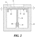
FIG. 2 is a sectional view taken along line A-A' of the radio frequency filter inFIG. 1 . -
FIG. 3 is a diagram illustrating an installation work performed on a resonance element in the radio frequency filter inFIG. 2 . -
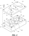
FIG. 4 is a partially exploded perspective view of a radio frequency filter having a cavity structure according to a second embodiment of the present disclosure. -
FIG. 5 is a partial sectional view taken along line A-A' inFIG. 4 . - Some embodiments of the present disclosure will now be described in detail with reference to the accompanying drawings.
-
FIG. 1 is a partially exploded perspective view of a radio frequency filter having a cavity structure according to a first embodiment of the present disclosure, wherein the dot-dash circle shows anadditional driver device 50 as a work tool for the installation work of aresonance element 30 for the sake of convenience of explanation.FIG. 2 is a sectional view taken along line A-A' of the radio frequency filter inFIG. 1 , which is completely assembled.FIG. 3 is a diagram illustrating the installation work performed on the resonance element in the radio frequency filter inFIG. 2 before itshousing 20 is fitted with acover 10 shown inFIG 2 . - Referring to
FIGS. 1 to 3 , the radio frequency filter having the cavity structure according to the first embodiment of the present disclosure, similar to prior art, is provided with an enclosure that has at least one cavity which is hollow inside and is isolated from the outside. The enclosure is formed including thehousing 20 having at least one cavity and an opening on one side (for example, the upper side), and thecover 10 for shielding the open side of thehousing 20.FIGS. 1 to 3 illustrate an example basic structure where, for example, a single-cavity structure is formed in thehousing 20. In addition, such a cavity is provided with oneresonance element 30, for example, at the center thereof. Thehousing 20 may be formed, on two side surfaces, with additional input/output terminals (not shown) of a usual structure for signal input/output to and from the radio frequency filter. - The
housing 20 and thecover 30 may be made of a material such as aluminum (alloy) or others, and in order to improve the electrical characteristics, at least the surface forming the cavity may be plated with silver or copper. Theresonance element 30 may also be made of a material such as aluminum (alloy), iron (alloy) or others, and it may be plated with silver or copper. - The physical structure of the cavity formed in the
housing 20 and in thecover 10 of the radio frequency filter according to the first embodiment of the present disclosure and the installment of theresonance element 30 inside the cavity may appear to be relatively similar to the prior art, except that they can be miniaturized in implementation. The improvement over the conventional structure, however, is in theresonant element 30 and the installation thereof, according to at least one embodiment of the present disclosure. - More specifically, the
resonant element 30 includes aplanar portion 32 that forms, in terms of circuitry, a capacitor (C) component of the filter and has, for example, a circular planar shape. Theresonant element 30 additionally includes a rod-like support 34 that forms, in terms of circuitry, an inductor (L) component and has a circular cross section. Thesupport 34 has an upper end portion formed to merge with theplanar portion 32 at its bottom side and a lower end portion installed fixedly and coupled with the enclosure, i.e., thehousing 20 to support theplanar portion 32. - In the above, the lower end portion of the
support 34 of theresonance element 30 is formed with amale thread structure 342 as a means for threaded coupling. In an arrangement complementary to themale thread structure 342, thehousing 20 is provided with afemale thread structure 24 to be screw connected to themale thread structure 342 formed at the lower end portion of thesupport 34 for fixing the latter. Thefemale thread structure 24 is formed, for example, to protrude from thehousing 20 at a portion corresponding to the bottom surface of the cavity. - At least two through
holes 322 are appropriately formed in theplanar portion 32 of theresonance element 30 at points symmetrical to each other with respect to, for example, the center of theplanar portion 32. The throughholes 322 are configured to engage, when performing the installation work of theresonance element 30, an external device, that is, thedriver device 50 for rotating theresonance element 30, and thereby themale thread structure 342 formed on thesupport 34 of thehousing 30 is screwed into the internal threadedstructure 24. - The
driver device 50 has at least twocoupling pins 522 disposed at locations corresponding to at least two throughholes 322 formed in theplanar portion 32 of theresonance element 30, and having a suitable size and a shape for being inserted into the throughholes 322 to establish an interconnection therebetween, as shown inFIGS. 1 and3 . With thedriver device 50, an operator may rotate therelevant resonance element 30, for example, in a clockwise direction by inserting the coupling pins 522 of thedriver device 50 into the throughholes 322 of theplanar portion 32 of theresonance element 30. As a result, themale thread structure 342 of thesupport 34 of theresonance element 30 is tightened to thefemale thread structure 24 of thehousing 20, whereby theresonance element 30 is installed on the bottom surface of thehousing 20. - In terms of installation, the above-described method with the
resonance element 30 seems somewhat similar to ordinary method of screw interconnection. However, different from the construction of the embodiments of the present disclosure, employing the ordinary method of screw interconnection alone would lead to a conceptual structure with a slot screw drive or a cross screw drive formed centrally of theplanar portion 32 of theresonance element 30 so that the drive can engage a typical screwdriver. Such conceptual structure requires theplanar portion 32 to have a relatively large thickness in order to form grooves into the aforementioned slot screw drive or cross screw drive. In comparison, according to some embodiments of the present disclosure, the structure forming the throughhole 322 is configured to make theplanar portion 32 of theresonance element 30 very thin. - Of the
resonance element 30, theplanar portion 32 and thesupport 34 form the C component and the L component of the relevant filter, respectively. For example, in order to reduce the filter size while maintaining the same L value as compared with a filter of a larger size, thesupport 34 needs to be designed to have a small diameter. In some embodiments of the present disclosure, the thickness of theplanar portion 32 of theresonance element 30 is designed to be very thin, and at the same time, thesupport 34 of theresonance element 30 required to stably support theplanar portion 32 can be designed to have a diameter further reduced. For example, the thickness (reference symbol't' inFIG. 2 ) of theplanar portion 32 may be designed to be, for example, about 0.5 mm or less. In addition, theplanar portion 32 of theresonance element 30 may be installed close to thecover 10 to increase the value of C component. For example, the distance (reference symbol 'd' inFIG. 2 ) between theplanar portion 32 and thecover 10 may be designed to be about 0.5 mm. In the example ofFIG. 2 at least, additional extensions formed are illustrated as extending somewhat further downward along the sides of the cavity from the side edges of theplanar portion 32, and these extensions help to increase the value of C of theplanar portion 32. - In addition, the
resonance element 30 may be silver-plated after it is generally made of a material such as iron (alloy) according to some embodiments of the present disclosure, which is to compensate for characteristic changes due to changes in the temperature of the filter. Specifically, in the environment of using the radio frequency filter, the sizes of the cavity and the resonant element expand as a whole as the temperature rises, which makes the center frequency of the filter deviated to the lower band. In some embodiments of the present disclosure, the resonance element is made of a material having a smaller thermal expansion coefficient (for example, iron) than the material of the housing and the cover (for example, an aluminum alloy) to increase the distance between the cover and the resonance element when the temperature rises, whereby compensating for the center frequency of the relevant filter deviating to the lower band. Theresonance element 30 may be made of other materials such as copper (Cu), brass (Bs) or the like which has a thermal expansion coefficient lower than that of the aluminum alloy. - The
cover 10 may have a structure similar to that aoolicable to the typical radio frequency filter with a cavity structure. For example, the structure may be similar to that of Korean Laid-Open Patent Publication No.10-2014-0026235 10-2014-0026235 cover 10 according to some embodiments of the present disclosure is formed with one or a plurality of recessed ordepression structures 12 as disclosed by Korean Laid-Open Patent Publication No.10-2014-0026235 depression structures 12 with marking pins of an external marking device. - According to other embodiments of the disclosure, on the one hand, a more generalized frequency tuning scheme is applied to the
cover 10 so as to form a frequency tuning screw and a fastening nut without such an arrangement as theaforementioned depression structures 12. The structure including the frequency tuning screw and the fastening nut described above, however, is relatively complicated to possibly make their miniaturization difficult. In addition, as the interval between thecover 10 and theresonant element 30 is designed to be smaller, the tuning is more difficult, so it may not be easy to adopt the structure comprising the tuning screw and the fastening nut. -
FIG. 4 is a partially exploded perspective view of a radio frequency filter having a cavity structure according to a second embodiment of the present disclosure. Referring toFIG. 4 , the radio frequency filter having a cavity structure according to the second embodiment of the present disclosure is provided with an enclosure that has a hollow interior and a plurality of (five in the example ofFIGS. 4 and5 ) cavities isolated from the outside. The enclosure is formed including ahousing 21 that has five cavities and an opening on one side (e.g., the upper side), and acover 11 for shielding the open side of thehousing 21. - In
FIG 4 , an example case is shown where, for example, five cavity structures are shown connected in multiple stages in thehousing 21. In other words, it can be regarded as a structure in which five cavity structures are sequentially interconnected. The cavities of the housing 22 have resonance elements 30-1, 30-2, 30-3, 30-4 and 30-5 centrally thereof, respectively. In addition, in order to make the respective cavity structures of thehousing 21 have a sequentially coupled arrangement therebetween, coupling windows are provided in the form of connecting passages between the cavity structures having the sequential interconnection structures. The coupling windows may be provided at portions corresponding to partition walls between the cavity structures with a predetermined area of the portions removed. - In the configuration shown in
FIG. 4 , at least some of the resonance elements 30-1, 30-2, 30-3, 30-4 and 30-5 may have the structure according to the first embodiment of the present disclosure shown inFIGS. 1 to 3 . For example, each of the second, third and fourth resonance elements 30-2, 30-3, 30-4 has a planar portion having a circular planar shape, and a support structure as shown inFIGS. 1 to 3 . The planar portion is formed with at least two through holes, and the support may be structured to be fixed to the bottom surface of the housing by a screw fastening method. -
FIG. 4 shows that, for example, the second and fourth resonance elements 30-2, 30-4 have, like the structure shown inFIGS. 1 to 3 , extensions formed extending downward along the sides of the cavity from the side edges of the planar portions, while the third resonance element 30-3 has no such extension. In addition, the first and fifth resonance elements 30-1, 30-5 may have a typical resonance element structure. As described above, in some embodiments of the present disclosure, resonance elements having a typical structure may be used together with resonance elements having the structure shown inFIGS. 1 to 3 . It is understood that, in other embodiments of the present disclosure, all resonant elements may have the same structure as that shown inFIGS. 1 to 3 . - Meanwhile, the
cover 11 may be formed with first to fifth depression structures 12-1, 12-2, 12-3, 12-4 and 12-5 for frequency tuning corresponding to the respective resonant elements in their cavity structures. Thecover 11 may be additionally formed with a plurality of coupling/tuning threadedholes 131 at positions in thecover 11 corresponding to coupling windows, which are connection path structures between the respective cavity structures of thehousing 21. A coupling/tuning screw (not shown) for tuning the coupling may be inserted into the coupling/tuning threadedhole 131 at an appropriate depth, so as to allow performing the tuning work of the coupling. At this time, the coupling tuning screw may be fixed in the proper position by using separate adhesive such as epoxy resin. - The
cover 11 and thehousing 21 may be fastend together by a screw fastening method with fastening screws 61. For example, throughholes 111 for screw fastening are formed at appropriate positions of thecover 11, and a plurality ofrecesses 211 for screw fastening is formed in thehousing 21 at portions corresponding to the throughholes 111. Thecover 11 and thehousing 21 may be coupled by driving the fastening screws 61 through the throughholes 111 of thecover 11 into therecesses 211 of the housing. It is understood that thecover 11 and thehousing 21 may also be joined by laser welding, soldering or the like. - Futher, as shown in
FIG. 4 , the radio frequency filter may have aninput terminal 41 and anoutput terminal 42 attached thereto via through holes each formed on a lateral side of thehousing 21 so that theterminals FIG. 5 shows theinput terminal 41 and the first resonance element 30-1 when they are fastened together in a manner that an extension line of theinput terminal 41 is directly connected to a support 34-1 of the first resonance element 30-1. It is understood that the radio frequency filter may be configured so that the extension line of the input terminal is connected to a support 34-1 by a non-contact coupling method. - As described above, a radio frequency filter having a cavity structure is configured according to some embodiments of the present disclosure, although there are various other embodiments and modifications in the present disclosure. For example, in the above description, the number of through holes formed in the planar portion of the resonant element is two, but different numbers of through holes such as three or four of them may be formed in different configurations of the radio frequency filter.
- In the second embodiment, for example, a filter structure is disclosed as having five cavities, although other filter structures may be configured to have two to four or more than six cavities. It is understood that, as is relevant to the filter structure, at least one or more resonant elements may be implemented as necessary so as to have the structure according to the first embodiment.
- As decribed above, there are various modifications and alterations of the present disclosure, and therefore, the scope of the present disclosure is not defined by the embodiments described, but by the claims and the equivalence of the claims.
Claims (6)
- A radio frequency filter having a cavity structure, the radio frequency filter comprising:a housing configured to have a hollow interior for providing at least one cavity and an open side;a cover configured to shield the open side of the housing; andat least one resonance element positioned in the hollow interior of the housing and having a planar portion and a support fixed to the housing and supporting the planar portion,wherein the planar portion of the at least one resonance element has at least two through holes formed so as to be connected to an external driver device and rotate a corresponding resonance element, and the support has a lower end portion formed with a male thread structure for screw fastening, andwherein the housing is formed with a female thread structure to be screw fastened with the male thread structure formed at the lower end portion of the support for fixing the support.
- The radio frequency filter of claim 1, wherein the external driver device comprises:at least two pins configured to be at positions corresponding to the at least two through holes formed in the planar portion, and to be inserted in the at least two through holes for an engagement with the at least two through holes.
- The radio frequency filter of claim 1, wherein the planar portion has a thickness of 0.5 mm or less.
- The radio frequency filter of claim 1, comprising a plurality of cavities and a resonance element provided for each of the plurality of cavities.
- The radio frequency filter of any one of claims 1 to 4, wherein the resonance element is made of a material having a coefficient of thermal expansion lower than a coefficient of thermal expansion of a material constituting the housing.
- The radio frequency filter of any one of claims 1 to 4, wherein the cover has at least one depression structure at a portion of the cover, corresponding to the resonance element for allowing a frequency tuning, the depression structure having a plurality of dot peens formed by an external marking device.
Applications Claiming Priority (2)
| Application Number | Priority Date | Filing Date | Title |
|---|---|---|---|
| KR1020150055070A KR101730084B1 (en) | 2015-04-20 | 2015-04-20 | Radio frequency filter with cavity structure |
| PCT/KR2016/001537 WO2016171380A1 (en) | 2015-04-20 | 2016-02-16 | Radio frequency filter having cavity structure |
Publications (3)
| Publication Number | Publication Date |
|---|---|
| EP3288108A1 true EP3288108A1 (en) | 2018-02-28 |
| EP3288108A4 EP3288108A4 (en) | 2018-12-19 |
| EP3288108B1 EP3288108B1 (en) | 2021-04-14 |
Family
ID=57143970
Family Applications (1)
| Application Number | Title | Priority Date | Filing Date |
|---|---|---|---|
| EP16783315.1A Active EP3288108B1 (en) | 2015-04-20 | 2016-02-16 | Radio frequency filter having cavity structure |
Country Status (5)
| Country | Link |
|---|---|
| US (1) | US10418677B2 (en) |
| EP (1) | EP3288108B1 (en) |
| KR (1) | KR101730084B1 (en) |
| CN (1) | CN107980188B (en) |
| WO (1) | WO2016171380A1 (en) |
Families Citing this family (3)
| Publication number | Priority date | Publication date | Assignee | Title |
|---|---|---|---|---|
| GB201904808D0 (en) * | 2019-04-05 | 2019-05-22 | Radio Design Ltd | Filter apparatus and method of use thereof |
| EP3956940A1 (en) * | 2019-04-15 | 2022-02-23 | Telefonaktiebolaget LM Ericsson (publ) | Integrated antenna and filter unit (iafu) for 5th generation advanced antenna system (aas) systems |
| US20230173672A1 (en) * | 2020-06-02 | 2023-06-08 | Commscope Technologies Llc | Smart hand tools with sensing and wireless capabilities, and systems and methods for using same |
Family Cites Families (13)
| Publication number | Priority date | Publication date | Assignee | Title |
|---|---|---|---|---|
| US2516056A (en) * | 1946-02-26 | 1950-07-18 | Rca Corp | Method for tuning cascade tuned circuits |
| FI96150C (en) * | 1994-07-19 | 1996-05-10 | Nokia Telecommunications Oy | Temperature compensated combiner |
| SE513293C2 (en) * | 1998-12-18 | 2000-08-21 | Ericsson Telefon Ab L M | Mounting device at contact transition |
| DE19917087C2 (en) | 1999-04-15 | 2001-07-26 | Kathrein Werke Kg | High frequency filter |
| KR20040020683A (en) * | 2002-08-31 | 2004-03-09 | 주식회사 케이엠더블유 | Radio frequency filter with spring nut |
| KR100489698B1 (en) | 2003-05-21 | 2005-05-17 | 주식회사 케이엠더블유 | Radio frequency filter |
| US7388457B2 (en) * | 2005-01-20 | 2008-06-17 | M/A-Com, Inc. | Dielectric resonator with variable diameter through hole and filter with such dielectric resonators |
| JP2011097463A (en) | 2009-10-30 | 2011-05-12 | Nec Toshiba Space Systems Ltd | Coaxial band-pass filter, coaxial resonator and microwave communication equipment |
| WO2012162948A1 (en) * | 2011-08-16 | 2012-12-06 | Huawei Technologies Co., Ltd. | A cavity microwave filter assembly, and a method for making a cavity microwave filter assembly |
| KR101869757B1 (en) * | 2012-02-27 | 2018-06-21 | 주식회사 케이엠더블유 | Radio frequency filter with cavity structure |
| KR102010269B1 (en) * | 2012-08-23 | 2019-08-13 | 주식회사 케이엠더블유 | Radio frequency filter with cavity structure |
| US9595746B2 (en) * | 2012-09-26 | 2017-03-14 | Nokia Solutions And Networks Oy | Semi-coaxial resonator comprised of columnar shaped resonant elements with square shaped plates, where vertical screw holes are disposed in the square shaped plates |
| CN103650237B (en) | 2013-08-09 | 2015-12-30 | 华为技术有限公司 | A kind of filter tuning apparatus and filter |
-
2015
- 2015-04-20 KR KR1020150055070A patent/KR101730084B1/en active Active
-
2016
- 2016-02-16 EP EP16783315.1A patent/EP3288108B1/en active Active
- 2016-02-16 CN CN201680022942.7A patent/CN107980188B/en active Active
- 2016-02-16 WO PCT/KR2016/001537 patent/WO2016171380A1/en not_active Ceased
-
2017
- 2017-10-20 US US15/789,953 patent/US10418677B2/en active Active
Also Published As
| Publication number | Publication date |
|---|---|
| CN107980188A (en) | 2018-05-01 |
| CN107980188B (en) | 2020-09-01 |
| KR20160124454A (en) | 2016-10-28 |
| KR101730084B1 (en) | 2017-04-25 |
| EP3288108A4 (en) | 2018-12-19 |
| US20180048043A1 (en) | 2018-02-15 |
| EP3288108B1 (en) | 2021-04-14 |
| US10418677B2 (en) | 2019-09-17 |
| WO2016171380A1 (en) | 2016-10-27 |
Similar Documents
| Publication | Publication Date | Title |
|---|---|---|
| KR101756124B1 (en) | Cavity type radio frequency filter with cross-coupling notch structure | |
| KR102204646B1 (en) | Radio frequency filter with cavity structure | |
| KR20230027139A (en) | Radio frequency filter | |
| CN107210506B (en) | RF filter with cavity structure | |
| KR200482481Y1 (en) | Radio frequency filter | |
| US20180048043A1 (en) | Radio frequency filter having cavity structure | |
| EP3236531A1 (en) | Two-part antenna element | |
| KR200467912Y1 (en) | Radio frequency filter with cavity structure | |
| JP3385909B2 (en) | Filter and transceiver | |
| CN115693056B (en) | Filter, manufacturing method thereof and antenna | |
| WO2013129817A1 (en) | Radio frequency filter having cavity structure | |
| JPH1084201A (en) | Dielectric resonator device | |
| JP5749077B2 (en) | TM mode dielectric resonator | |
| JPS59101902A (en) | Dielectric filter | |
| US9642265B2 (en) | Dense out of plane interconnect inside hermetically sealed modules | |
| US9699944B2 (en) | Methods and devices for reducing communication and power signal leakages from filter assemblies | |
| JP2001136008A (en) | Microwave waveguide device | |
| JP2005086532A (en) | Dielectric resonator and dielectric bandpass filter | |
| JP4273083B2 (en) | Wireless signal transmitter / receiver | |
| JPS594203A (en) | Dielectric filter | |
| JPH0951201A (en) | Dielectric resonator and dielectric resonator device | |
| US8830698B2 (en) | Methods and devices for reducing communication and power signal leakages from filter assemblies | |
| JPH08222905A (en) | Dielectric resonator | |
| JP2005260027A (en) | High frequency circuit module | |
| KR101596234B1 (en) | A case for semi-conductor pulse amplifier used for high frequency |
Legal Events
| Date | Code | Title | Description |
|---|---|---|---|
| STAA | Information on the status of an ep patent application or granted ep patent |
Free format text: STATUS: THE INTERNATIONAL PUBLICATION HAS BEEN MADE |
|
| PUAI | Public reference made under article 153(3) epc to a published international application that has entered the european phase |
Free format text: ORIGINAL CODE: 0009012 |
|
| STAA | Information on the status of an ep patent application or granted ep patent |
Free format text: STATUS: REQUEST FOR EXAMINATION WAS MADE |
|
| 17P | Request for examination filed |
Effective date: 20171110 |
|
| AK | Designated contracting states |
Kind code of ref document: A1 Designated state(s): AL AT BE BG CH CY CZ DE DK EE ES FI FR GB GR HR HU IE IS IT LI LT LU LV MC MK MT NL NO PL PT RO RS SE SI SK SM TR |
|
| AX | Request for extension of the european patent |
Extension state: BA ME |
|
| DAV | Request for validation of the european patent (deleted) | ||
| DAX | Request for extension of the european patent (deleted) | ||
| REG | Reference to a national code |
Ref country code: DE Ref legal event code: R079 Ref document number: 602016056122 Country of ref document: DE Free format text: PREVIOUS MAIN CLASS: H01P0001200000 Ipc: H01P0001205000 |
|
| A4 | Supplementary search report drawn up and despatched |
Effective date: 20181115 |
|
| RIC1 | Information provided on ipc code assigned before grant |
Ipc: H01P 1/205 20060101AFI20181109BHEP Ipc: H01P 7/04 20060101ALI20181109BHEP |
|
| GRAP | Despatch of communication of intention to grant a patent |
Free format text: ORIGINAL CODE: EPIDOSNIGR1 |
|
| STAA | Information on the status of an ep patent application or granted ep patent |
Free format text: STATUS: GRANT OF PATENT IS INTENDED |
|
| INTG | Intention to grant announced |
Effective date: 20201104 |
|
| GRAS | Grant fee paid |
Free format text: ORIGINAL CODE: EPIDOSNIGR3 |
|
| GRAA | (expected) grant |
Free format text: ORIGINAL CODE: 0009210 |
|
| STAA | Information on the status of an ep patent application or granted ep patent |
Free format text: STATUS: THE PATENT HAS BEEN GRANTED |
|
| AK | Designated contracting states |
Kind code of ref document: B1 Designated state(s): AL AT BE BG CH CY CZ DE DK EE ES FI FR GB GR HR HU IE IS IT LI LT LU LV MC MK MT NL NO PL PT RO RS SE SI SK SM TR |
|
| REG | Reference to a national code |
Ref country code: GB Ref legal event code: FG4D |
|
| REG | Reference to a national code |
Ref country code: CH Ref legal event code: EP |
|
| REG | Reference to a national code |
Ref country code: DE Ref legal event code: R096 Ref document number: 602016056122 Country of ref document: DE |
|
| REG | Reference to a national code |
Ref country code: IE Ref legal event code: FG4D |
|
| REG | Reference to a national code |
Ref country code: AT Ref legal event code: REF Ref document number: 1383275 Country of ref document: AT Kind code of ref document: T Effective date: 20210515 |
|
| REG | Reference to a national code |
Ref country code: FI Ref legal event code: FGE |
|
| REG | Reference to a national code |
Ref country code: SE Ref legal event code: TRGR |
|
| REG | Reference to a national code |
Ref country code: LT Ref legal event code: MG9D |
|
| REG | Reference to a national code |
Ref country code: AT Ref legal event code: MK05 Ref document number: 1383275 Country of ref document: AT Kind code of ref document: T Effective date: 20210414 |
|
| REG | Reference to a national code |
Ref country code: NL Ref legal event code: MP Effective date: 20210414 |
|
| PG25 | Lapsed in a contracting state [announced via postgrant information from national office to epo] |
Ref country code: HR Free format text: LAPSE BECAUSE OF FAILURE TO SUBMIT A TRANSLATION OF THE DESCRIPTION OR TO PAY THE FEE WITHIN THE PRESCRIBED TIME-LIMIT Effective date: 20210414 Ref country code: BG Free format text: LAPSE BECAUSE OF FAILURE TO SUBMIT A TRANSLATION OF THE DESCRIPTION OR TO PAY THE FEE WITHIN THE PRESCRIBED TIME-LIMIT Effective date: 20210714 Ref country code: AT Free format text: LAPSE BECAUSE OF FAILURE TO SUBMIT A TRANSLATION OF THE DESCRIPTION OR TO PAY THE FEE WITHIN THE PRESCRIBED TIME-LIMIT Effective date: 20210414 Ref country code: NL Free format text: LAPSE BECAUSE OF FAILURE TO SUBMIT A TRANSLATION OF THE DESCRIPTION OR TO PAY THE FEE WITHIN THE PRESCRIBED TIME-LIMIT Effective date: 20210414 Ref country code: LT Free format text: LAPSE BECAUSE OF FAILURE TO SUBMIT A TRANSLATION OF THE DESCRIPTION OR TO PAY THE FEE WITHIN THE PRESCRIBED TIME-LIMIT Effective date: 20210414 |
|
| PG25 | Lapsed in a contracting state [announced via postgrant information from national office to epo] |
Ref country code: PT Free format text: LAPSE BECAUSE OF FAILURE TO SUBMIT A TRANSLATION OF THE DESCRIPTION OR TO PAY THE FEE WITHIN THE PRESCRIBED TIME-LIMIT Effective date: 20210816 Ref country code: NO Free format text: LAPSE BECAUSE OF FAILURE TO SUBMIT A TRANSLATION OF THE DESCRIPTION OR TO PAY THE FEE WITHIN THE PRESCRIBED TIME-LIMIT Effective date: 20210714 Ref country code: PL Free format text: LAPSE BECAUSE OF FAILURE TO SUBMIT A TRANSLATION OF THE DESCRIPTION OR TO PAY THE FEE WITHIN THE PRESCRIBED TIME-LIMIT Effective date: 20210414 Ref country code: RS Free format text: LAPSE BECAUSE OF FAILURE TO SUBMIT A TRANSLATION OF THE DESCRIPTION OR TO PAY THE FEE WITHIN THE PRESCRIBED TIME-LIMIT Effective date: 20210414 Ref country code: IS Free format text: LAPSE BECAUSE OF FAILURE TO SUBMIT A TRANSLATION OF THE DESCRIPTION OR TO PAY THE FEE WITHIN THE PRESCRIBED TIME-LIMIT Effective date: 20210814 Ref country code: LV Free format text: LAPSE BECAUSE OF FAILURE TO SUBMIT A TRANSLATION OF THE DESCRIPTION OR TO PAY THE FEE WITHIN THE PRESCRIBED TIME-LIMIT Effective date: 20210414 Ref country code: GR Free format text: LAPSE BECAUSE OF FAILURE TO SUBMIT A TRANSLATION OF THE DESCRIPTION OR TO PAY THE FEE WITHIN THE PRESCRIBED TIME-LIMIT Effective date: 20210715 |
|
| REG | Reference to a national code |
Ref country code: DE Ref legal event code: R097 Ref document number: 602016056122 Country of ref document: DE |
|
| PG25 | Lapsed in a contracting state [announced via postgrant information from national office to epo] |
Ref country code: SM Free format text: LAPSE BECAUSE OF FAILURE TO SUBMIT A TRANSLATION OF THE DESCRIPTION OR TO PAY THE FEE WITHIN THE PRESCRIBED TIME-LIMIT Effective date: 20210414 Ref country code: SK Free format text: LAPSE BECAUSE OF FAILURE TO SUBMIT A TRANSLATION OF THE DESCRIPTION OR TO PAY THE FEE WITHIN THE PRESCRIBED TIME-LIMIT Effective date: 20210414 Ref country code: RO Free format text: LAPSE BECAUSE OF FAILURE TO SUBMIT A TRANSLATION OF THE DESCRIPTION OR TO PAY THE FEE WITHIN THE PRESCRIBED TIME-LIMIT Effective date: 20210414 Ref country code: ES Free format text: LAPSE BECAUSE OF FAILURE TO SUBMIT A TRANSLATION OF THE DESCRIPTION OR TO PAY THE FEE WITHIN THE PRESCRIBED TIME-LIMIT Effective date: 20210413 Ref country code: EE Free format text: LAPSE BECAUSE OF FAILURE TO SUBMIT A TRANSLATION OF THE DESCRIPTION OR TO PAY THE FEE WITHIN THE PRESCRIBED TIME-LIMIT Effective date: 20210414 Ref country code: CZ Free format text: LAPSE BECAUSE OF FAILURE TO SUBMIT A TRANSLATION OF THE DESCRIPTION OR TO PAY THE FEE WITHIN THE PRESCRIBED TIME-LIMIT Effective date: 20210414 Ref country code: DK Free format text: LAPSE BECAUSE OF FAILURE TO SUBMIT A TRANSLATION OF THE DESCRIPTION OR TO PAY THE FEE WITHIN THE PRESCRIBED TIME-LIMIT Effective date: 20210414 |
|
| PLBE | No opposition filed within time limit |
Free format text: ORIGINAL CODE: 0009261 |
|
| STAA | Information on the status of an ep patent application or granted ep patent |
Free format text: STATUS: NO OPPOSITION FILED WITHIN TIME LIMIT |
|
| 26N | No opposition filed |
Effective date: 20220117 |
|
| PG25 | Lapsed in a contracting state [announced via postgrant information from national office to epo] |
Ref country code: IS Free format text: LAPSE BECAUSE OF FAILURE TO SUBMIT A TRANSLATION OF THE DESCRIPTION OR TO PAY THE FEE WITHIN THE PRESCRIBED TIME-LIMIT Effective date: 20210814 Ref country code: AL Free format text: LAPSE BECAUSE OF FAILURE TO SUBMIT A TRANSLATION OF THE DESCRIPTION OR TO PAY THE FEE WITHIN THE PRESCRIBED TIME-LIMIT Effective date: 20210414 |
|
| PG25 | Lapsed in a contracting state [announced via postgrant information from national office to epo] |
Ref country code: IT Free format text: LAPSE BECAUSE OF FAILURE TO SUBMIT A TRANSLATION OF THE DESCRIPTION OR TO PAY THE FEE WITHIN THE PRESCRIBED TIME-LIMIT Effective date: 20210414 |
|
| REG | Reference to a national code |
Ref country code: DE Ref legal event code: R119 Ref document number: 602016056122 Country of ref document: DE |
|
| PG25 | Lapsed in a contracting state [announced via postgrant information from national office to epo] |
Ref country code: MC Free format text: LAPSE BECAUSE OF FAILURE TO SUBMIT A TRANSLATION OF THE DESCRIPTION OR TO PAY THE FEE WITHIN THE PRESCRIBED TIME-LIMIT Effective date: 20210414 |
|
| REG | Reference to a national code |
Ref country code: CH Ref legal event code: PL |
|
| REG | Reference to a national code |
Ref country code: BE Ref legal event code: MM Effective date: 20220228 |
|
| GBPC | Gb: european patent ceased through non-payment of renewal fee |
Effective date: 20220216 |
|
| PG25 | Lapsed in a contracting state [announced via postgrant information from national office to epo] |
Ref country code: LU Free format text: LAPSE BECAUSE OF NON-PAYMENT OF DUE FEES Effective date: 20220216 |
|
| PG25 | Lapsed in a contracting state [announced via postgrant information from national office to epo] |
Ref country code: FR Free format text: LAPSE BECAUSE OF NON-PAYMENT OF DUE FEES Effective date: 20220228 |
|
| PG25 | Lapsed in a contracting state [announced via postgrant information from national office to epo] |
Ref country code: LI Free format text: LAPSE BECAUSE OF NON-PAYMENT OF DUE FEES Effective date: 20220228 Ref country code: IE Free format text: LAPSE BECAUSE OF NON-PAYMENT OF DUE FEES Effective date: 20220216 Ref country code: GB Free format text: LAPSE BECAUSE OF NON-PAYMENT OF DUE FEES Effective date: 20220216 Ref country code: DE Free format text: LAPSE BECAUSE OF NON-PAYMENT OF DUE FEES Effective date: 20220901 Ref country code: CH Free format text: LAPSE BECAUSE OF NON-PAYMENT OF DUE FEES Effective date: 20220228 |
|
| PG25 | Lapsed in a contracting state [announced via postgrant information from national office to epo] |
Ref country code: BE Free format text: LAPSE BECAUSE OF NON-PAYMENT OF DUE FEES Effective date: 20220228 |
|
| PG25 | Lapsed in a contracting state [announced via postgrant information from national office to epo] |
Ref country code: HU Free format text: LAPSE BECAUSE OF FAILURE TO SUBMIT A TRANSLATION OF THE DESCRIPTION OR TO PAY THE FEE WITHIN THE PRESCRIBED TIME-LIMIT; INVALID AB INITIO Effective date: 20160216 |
|
| PG25 | Lapsed in a contracting state [announced via postgrant information from national office to epo] |
Ref country code: MK Free format text: LAPSE BECAUSE OF FAILURE TO SUBMIT A TRANSLATION OF THE DESCRIPTION OR TO PAY THE FEE WITHIN THE PRESCRIBED TIME-LIMIT Effective date: 20210414 Ref country code: CY Free format text: LAPSE BECAUSE OF FAILURE TO SUBMIT A TRANSLATION OF THE DESCRIPTION OR TO PAY THE FEE WITHIN THE PRESCRIBED TIME-LIMIT Effective date: 20210414 |
|
| PG25 | Lapsed in a contracting state [announced via postgrant information from national office to epo] |
Ref country code: TR Free format text: LAPSE BECAUSE OF FAILURE TO SUBMIT A TRANSLATION OF THE DESCRIPTION OR TO PAY THE FEE WITHIN THE PRESCRIBED TIME-LIMIT Effective date: 20210414 |
|
| PG25 | Lapsed in a contracting state [announced via postgrant information from national office to epo] |
Ref country code: MT Free format text: LAPSE BECAUSE OF FAILURE TO SUBMIT A TRANSLATION OF THE DESCRIPTION OR TO PAY THE FEE WITHIN THE PRESCRIBED TIME-LIMIT Effective date: 20210414 |
|
| PGFP | Annual fee paid to national office [announced via postgrant information from national office to epo] |
Ref country code: FI Payment date: 20251230 Year of fee payment: 11 |
|
| PGFP | Annual fee paid to national office [announced via postgrant information from national office to epo] |
Ref country code: SE Payment date: 20251210 Year of fee payment: 11 |