EP3287844B1 - A method in relation to acquiring digital images - Google Patents
A method in relation to acquiring digital images Download PDFInfo
- Publication number
- EP3287844B1 EP3287844B1 EP17184995.3A EP17184995A EP3287844B1 EP 3287844 B1 EP3287844 B1 EP 3287844B1 EP 17184995 A EP17184995 A EP 17184995A EP 3287844 B1 EP3287844 B1 EP 3287844B1
- Authority
- EP
- European Patent Office
- Prior art keywords
- digital camera
- image
- digital
- camera
- user
- Prior art date
- Legal status (The legal status is an assumption and is not a legal conclusion. Google has not performed a legal analysis and makes no representation as to the accuracy of the status listed.)
- Active
Links
- 238000000034 method Methods 0.000 title claims description 55
- 230000004044 response Effects 0.000 claims description 8
- 238000001514 detection method Methods 0.000 claims description 7
- 238000013459 approach Methods 0.000 claims description 3
- 239000003550 marker Substances 0.000 claims 4
- 230000005236 sound signal Effects 0.000 description 16
- 238000004458 analytical method Methods 0.000 description 12
- 238000001454 recorded image Methods 0.000 description 10
- 238000004891 communication Methods 0.000 description 6
- 238000003384 imaging method Methods 0.000 description 3
- 230000003287 optical effect Effects 0.000 description 3
- 238000010408 sweeping Methods 0.000 description 3
- 230000000007 visual effect Effects 0.000 description 3
- 230000003247 decreasing effect Effects 0.000 description 2
- 230000002441 reversible effect Effects 0.000 description 2
- 230000003213 activating effect Effects 0.000 description 1
- 230000009849 deactivation Effects 0.000 description 1
- 230000007423 decrease Effects 0.000 description 1
- 230000001419 dependent effect Effects 0.000 description 1
- 239000011159 matrix material Substances 0.000 description 1
- 230000000717 retained effect Effects 0.000 description 1
- 230000015541 sensory perception of touch Effects 0.000 description 1
- 230000001360 synchronised effect Effects 0.000 description 1
Images

Classifications
-
- G—PHYSICS
- G03—PHOTOGRAPHY; CINEMATOGRAPHY; ANALOGOUS TECHNIQUES USING WAVES OTHER THAN OPTICAL WAVES; ELECTROGRAPHY; HOLOGRAPHY
- G03B—APPARATUS OR ARRANGEMENTS FOR TAKING PHOTOGRAPHS OR FOR PROJECTING OR VIEWING THEM; APPARATUS OR ARRANGEMENTS EMPLOYING ANALOGOUS TECHNIQUES USING WAVES OTHER THAN OPTICAL WAVES; ACCESSORIES THEREFOR
- G03B37/00—Panoramic or wide-screen photography; Photographing extended surfaces, e.g. for surveying; Photographing internal surfaces, e.g. of pipe
-
- G—PHYSICS
- G03—PHOTOGRAPHY; CINEMATOGRAPHY; ANALOGOUS TECHNIQUES USING WAVES OTHER THAN OPTICAL WAVES; ELECTROGRAPHY; HOLOGRAPHY
- G03B—APPARATUS OR ARRANGEMENTS FOR TAKING PHOTOGRAPHS OR FOR PROJECTING OR VIEWING THEM; APPARATUS OR ARRANGEMENTS EMPLOYING ANALOGOUS TECHNIQUES USING WAVES OTHER THAN OPTICAL WAVES; ACCESSORIES THEREFOR
- G03B17/00—Details of cameras or camera bodies; Accessories therefor
- G03B17/18—Signals indicating condition of a camera member or suitability of light
-
- G—PHYSICS
- G03—PHOTOGRAPHY; CINEMATOGRAPHY; ANALOGOUS TECHNIQUES USING WAVES OTHER THAN OPTICAL WAVES; ELECTROGRAPHY; HOLOGRAPHY
- G03B—APPARATUS OR ARRANGEMENTS FOR TAKING PHOTOGRAPHS OR FOR PROJECTING OR VIEWING THEM; APPARATUS OR ARRANGEMENTS EMPLOYING ANALOGOUS TECHNIQUES USING WAVES OTHER THAN OPTICAL WAVES; ACCESSORIES THEREFOR
- G03B35/00—Stereoscopic photography
- G03B35/16—Stereoscopic photography by sequential viewing
-
- G—PHYSICS
- G03—PHOTOGRAPHY; CINEMATOGRAPHY; ANALOGOUS TECHNIQUES USING WAVES OTHER THAN OPTICAL WAVES; ELECTROGRAPHY; HOLOGRAPHY
- G03B—APPARATUS OR ARRANGEMENTS FOR TAKING PHOTOGRAPHS OR FOR PROJECTING OR VIEWING THEM; APPARATUS OR ARRANGEMENTS EMPLOYING ANALOGOUS TECHNIQUES USING WAVES OTHER THAN OPTICAL WAVES; ACCESSORIES THEREFOR
- G03B37/00—Panoramic or wide-screen photography; Photographing extended surfaces, e.g. for surveying; Photographing internal surfaces, e.g. of pipe
- G03B37/02—Panoramic or wide-screen photography; Photographing extended surfaces, e.g. for surveying; Photographing internal surfaces, e.g. of pipe with scanning movement of lens or cameras
-
- G—PHYSICS
- G06—COMPUTING; CALCULATING OR COUNTING
- G06T—IMAGE DATA PROCESSING OR GENERATION, IN GENERAL
- G06T7/00—Image analysis
- G06T7/20—Analysis of motion
-
- H—ELECTRICITY
- H04—ELECTRIC COMMUNICATION TECHNIQUE
- H04N—PICTORIAL COMMUNICATION, e.g. TELEVISION
- H04N23/00—Cameras or camera modules comprising electronic image sensors; Control thereof
- H04N23/60—Control of cameras or camera modules
- H04N23/63—Control of cameras or camera modules by using electronic viewfinders
- H04N23/633—Control of cameras or camera modules by using electronic viewfinders for displaying additional information relating to control or operation of the camera
-
- H—ELECTRICITY
- H04—ELECTRIC COMMUNICATION TECHNIQUE
- H04N—PICTORIAL COMMUNICATION, e.g. TELEVISION
- H04N23/00—Cameras or camera modules comprising electronic image sensors; Control thereof
- H04N23/60—Control of cameras or camera modules
- H04N23/64—Computer-aided capture of images, e.g. transfer from script file into camera, check of taken image quality, advice or proposal for image composition or decision on when to take image
-
- H—ELECTRICITY
- H04—ELECTRIC COMMUNICATION TECHNIQUE
- H04N—PICTORIAL COMMUNICATION, e.g. TELEVISION
- H04N23/00—Cameras or camera modules comprising electronic image sensors; Control thereof
- H04N23/60—Control of cameras or camera modules
- H04N23/68—Control of cameras or camera modules for stable pick-up of the scene, e.g. compensating for camera body vibrations
- H04N23/681—Motion detection
- H04N23/6812—Motion detection based on additional sensors, e.g. acceleration sensors
-
- H—ELECTRICITY
- H04—ELECTRIC COMMUNICATION TECHNIQUE
- H04N—PICTORIAL COMMUNICATION, e.g. TELEVISION
- H04N23/00—Cameras or camera modules comprising electronic image sensors; Control thereof
- H04N23/60—Control of cameras or camera modules
- H04N23/698—Control of cameras or camera modules for achieving an enlarged field of view, e.g. panoramic image capture
-
- G—PHYSICS
- G06—COMPUTING; CALCULATING OR COUNTING
- G06T—IMAGE DATA PROCESSING OR GENERATION, IN GENERAL
- G06T2207/00—Indexing scheme for image analysis or image enhancement
- G06T2207/10—Image acquisition modality
- G06T2207/10016—Video; Image sequence
Definitions
- the present invention relates to a method for acquiring at least two digital images by means of a digital camera, wherein the digital images are to be stitched into a combined image.
- an image with a wide field of view may often be desired. This may be artificially created by capturing a plurality of images which are then stitched together to create a large image of the landscape.
- a most effective result of the stitched image may be obtained by capturing images that are suitable for being stitched together.
- the images should be captured with an appropriate overlap and a good alignment.
- An overlap is needed to enable the images to be seamlessly stitched together.
- the final panoramic image is limited in the vertical direction by the top of the lowest image of the plurality of images forming the panorama, and the bottom of the highest image.
- a good alignment will enable the final panoramic image to be created with a maximum or near maximum vertical size.
- the display simultaneously shows to the user a part of the image that was previously recorded and a part of the image that will be recorded. This helps the user to correctly align and correlate the images to each other.
- a panoramic viewfinder is used, which simultaneously shows three different types of information to the user; (1) a preview shows the panorama in its current state of completion, (2) the viewfinder shows what the camera sees at the moment, and (3) the real-time cropping frame shows the extent the panorama will have after cropping if the user stopped shooting at this instant.
- panoramic images are often captured in a bright environment, which makes it hard to view an overlap of images and therefore the display is ineffective in helping the user in the image-taking process. Further, if a self-portrait is desired, the user is not able to see the viewfinder and is not helped at all.
- US 2006/0050152 A1 relates to a method for stitching digital images together onboard a digital imaging device.
- a first image is captured and portions of said first image are retained in a viewfinder of the digital image device on the display with which a live image can be aligned by a user.
- EP 1 613 060 A1 relates to a method of capturing a sequence of images by an imaging device. After having captured and stored at least one image, a user is guided to move the imaging device so that an image that can be stitched to said at least one stored image can be captured.
- the term "combined image” should be construed as an image that is formed from a combination of at least two captured images.
- the captured images may be formed into a panoramic image that is oblong and shows a wide angle of a scenery.
- the captured images may be related to each other in any way. For example, they may form a matrix of n times m images, where n and m are arbitrary numbers.
- the combined image need not be rectangular.
- the captured images may be stitched together to form a combined image of an arbitrary shape.
- a method for acquiring at least two digital images by means of a digital camera, wherein the digital images are to be stitched into a combined image comprises capturing a first digital image, wherein a first scenery is imaged; determining a relation between the first scenery and a second scenery being viewed by the digital camera, while said second scenery being viewed by the digital camera is changed; analysing the relation between the first scenery and the second scenery being viewed by the digital camera in order to identify an appropriate view to be captured by the digital camera in a second digital image for facilitating stitching of the first and second digital images; and indicating to the user that the camera is directed towards an appropriate view for capturing a second digital image, wherein said indicating comprises emitting a signal that is tactile for a user.
- the digital camera determines the relationship between the previously captured image and the image to be captured.
- the camera itself determines the view to be imaged in the image to be captured.
- the user is then guided by an indication from the digital camera that the camera is properly directed for capturing an image.
- guidance of a user for aiding in acquiring combined images may be accomplished in bright environments and even when a user is not able to see the viewfinder (such as when taking a self-portrait).
- the method deprives the user of the control of the capturing of the images since the second scenery to be imaged is determined by the camera. However, this enables the camera to guide the user in a more effective manner.
- the indication to the user that the camera is directed towards an appropriate view need not necessarily guide the user to an optimal view for capturing a second digital image.
- the indication may provide information to the user of how far away the present view is from an optimal view. The user may thus use this information to control capturing of a second digital image when the user finds it appropriate.
- the indication may inform the user of a situation when the camera is being moved in a direction away from a suitable view of a second image. In this situation, an indication may be given that a second image is to be captured before the camera is moved so far away from the suitable view that the captured images are no longer suited to be stitched at all.
- the indication may force a second image to be captured, wherein the second image is not depicting a particularly suitable view for stitching, but the second image is depicting a view that is able to be stitched to the first image.
- the human body responds very quickly to the tactile sense. Therefore, by emitting any kind of message or signal that may be sensed by the user, the user may very quickly react to the signal.
- the tactile signal may be accomplished in different ways. It may be in form of a small electric impulse, a change in temperature or a sensed vibration.
- the emitting may comprise activating a vibrator to inform a user of the relation between the first scenery and the second scenery.
- the vibrator may be activated during tracking when the digital camera is moved and be deactivated to indicate that the camera is directed towards an appropriate view for capturing an image. This implies that the user may be continuously guided in the movement of the camera. The guidance is not affected by a bright or noisy environment, since the user may sense the deactivation of the vibrator by means of his hand holding the camera. The user will then know that the camera has been properly directed.
- the vibrator may be used in other ways to communicate with the user.
- the vibrator may be used in the reverse manner, i.e. the vibrator being activated for a short period of time when the camera has been properly directed.
- the intensity of the vibrator may alternatively be varied in order to communicate to the user how far away the camera is from being directed towards an appropriate or an optimal view.
- a method for acquiring at least two digital images by means of a digital camera, wherein the digital images are to be stitched into a combined image comprises capturing a first digital image, wherein a first scenery is imaged; determining a relation between the first scenery and a second scenery being viewed by the digital camera, while said second scenery being viewed by the digital camera is changed; analysing the relation between the first scenery and the second scenery being viewed by the digital camera in order to identify an appropriate view to be captured by the digital camera in a second digital image for facilitating stitching of the first and second digital images; and indicating to the user that the camera is directed towards an appropriate view for capturing a second digital image, wherein said indicating comprises emitting a sound signal.
- the digital camera determines the relationship between the previously captured image and the image to be captured.
- the camera itself determines the view to be imaged in the image to be captured.
- the user is then guided by an indication from the digital camera that the camera is properly directed for capturing an image.
- guidance of a user for aiding in acquiring combined images may be accomplished in bright environments and even when a user is not able to see the viewfinder (such as when taking a self-portrait).
- the method deprives the user of the control of the capturing of the images since the second scenery to be imaged is determined by the camera. However, this enables the camera to guide the user in a more effective manner.
- the indication to the user that the camera is directed towards an appropriate view need not necessarily guide the user to an optimal view for capturing a second digital image.
- the indication may provide information to the user of how far away the present view is from an optimal view. The user may thus use this information to control capturing of a second digital image when the user finds it appropriate.
- the indication may inform the user of a situation when the camera is being moved in a direction away from a suitable view of a second image. In this situation, an indication may be given that a second image is to be captured before the camera is moved so far away from the suitable view that the captured images are no longer suited to be stitched at all.
- the indication may force a second image to be captured, wherein the second image is not depicting a particularly suitable view for stitching, but the second image is depicting a view that is able to be stitched to the first image.
- the emitting of a sound signal may comprise emitting a sound signal to inform a user of the relation between the first scenery and the second scenery.
- the emitting of the sound signal may be activated during tracking when the digital camera is moved and be deactivated to indicate that the camera is directed towards an appropriate view for capturing an image. The user will then know that the camera has been properly directed. This implies that the user may be continuously guided in the movement of the camera and the guidance is not affected by a bright environment.
- the sound signal may be used in other ways to communicate with the user.
- the sound signal may e.g. be used in the reverse manner, i.e. the emitting of the sound signal is activated for a short period of time when the camera has been properly directed.
- the intensity of the sound signal may alternatively be varied in order to communicate to the user how far away the camera is from being directed towards an appropriate or an optimal view.
- the second scenery may change in different ways.
- the scenery may change by movements taking place in front of the camera.
- the camera may be held still, while the scenery in front of the camera is changing.
- several images may be taken by a stationary camera. Movements in relation to a background may then be illustrated in the combined image.
- the combined image may thus be a combination of several images that are placed on top of each other.
- the second scenery may change by the camera being moved.
- the determining may comprise keeping track of a position of the first scenery in relation to the second scenery being viewed by the digital camera, while the digital camera is moved to change said second scenery being viewed by the digital camera. In this case, the camera is being moved and, thus, the scenery being viewed by the camera is changed.
- the relation between the first scenery and the changing second scenery is monitored in order to enable a second image to be captured that is suitable for stitching to the first image.
- keeping track of a position of the first scenery in relation to the second scenery comprises comparing images. This implies that movement of the camera is monitored by comparing views towards which the camera is being directed. This may be realized, for instance, by continuously comparing temporary small images being captured by the viewfinder. A comparison may be made to any of the previously captured temporary images in order to constantly update the relation between the second scenery and the first scenery.
- keeping track of a position of the first scenery in relation to the second scenery comprises sensing a change in direction of the digital camera.
- the sensing may be achieved e.g. by means of a gyroscope, that detects any rotation of the digital camera.
- the sensing may be achieved by means of a compass, whereby rotations in relation to the earth's magnetic field may be detected.
- an allowed rotation of the digital camera may be set.
- the method may further comprise communicating information to the user related to the change of the second scenery.
- the camera may give the user information of the status of a movement of the camera and thereby guide the movement such that the camera may be directed towards an appropriate part of the scenery.
- the communicating may comprise displaying a schematic representation of the relation between the first scenery and the second scenery being viewed by the digital camera. This enables a user to be guided in a bright environment when the details of the viewfinder are difficult to discern.
- the method may further comprise capturing a second digital image when the camera is directed towards an appropriate view, said capturing being automatically performed by the digital camera.
- the communication of information related to the movement of the camera to the user may allow the user to temporarily stop moving the camera at various positions when it is indicated that an image is to be acquired.
- motion blur is prevented and high quality sharp images may be acquired.
- This method allows several images that are to form a combined image to be captured very quickly.
- the user simply pushes the capture button to start acquiring the images and then sweeps the camera over the scenery to be imaged.
- the user is continuously guided when to temporarily stop sweeping the camera to allow another image to be captured.
- the user will not need to take any decisions regarding when to capture images.
- the user may merely follow instructions communicated by the camera.
- the user will not need to see the viewfinder of the camera and may thus acquire a self-portrait or a combined image in bright or dark environment.
- the indicating may comprise communicating information to the user that an image will be automatically captured in advance of the actual capture of the image. This implies that the user will be able to stop movement of the digital camera before the second digital image is captured. Thus, motion blur may effectively be eliminated.
- the automatic capture may be performed a predefined period of time after information is communicated to the user that a second image is about to be captured. Alternatively, the automatic capture may be performed in response to detection that the movement of the camera has been stopped.
- the analysing may use a predefined desired overlap between adjacent images for identifying an appropriate view. This overlap may be set to fit the optical set-up of the camera and, thus, optimal combined images may be obtained by using a programmed algorithm for acquiring images.
- the analysing may comprise determining whether conditions prevail that are appropriate for capturing a second digital image.
- the analysis may detect that the camera is hardly being moved. In such case, the conditions are such that a second image may appropriately be captured. Since the camera is only slightly moved, if moved at all, motion blur may be avoided. Thus, if the camera is aimed at a view that may be appropriate for stitching and these non-movement conditions of the camera prevail, a decision may be taken to capture a second digital image.
- the analysis may detect that the camera is directed towards a view being particularly suited for stitching to previously captured images. This may be detected as appropriate conditions for capturing a second digital image, even if the camera is being moved at the time. An indication may then be communicated to the user that an image will soon be captured allowing the user to stop the movement of the camera at the appropriate position. Thereafter, a second digital image is captured.
- the method may further comprise displaying an animation of desired movement of the digital camera, wherein the animation is synchronised with the actual movement of the digital camera.
- This animation gives the user an easy understanding of how to move the camera.
- the animation may show to the user that the camera is merely to be rotated and that neither any linear movement of the camera nor any tilting movement of the camera is to be made if a panoramic image is to be captured.
- a method for acquiring at least two digital images by means of a digital camera, wherein the digital images are to be stitched into a combined image comprises: capturing a first digital image, wherein a first scenery is imaged; allowing a user to move the digital camera to direct the camera towards a second scenery partly overlapping the first scenery; communicating to a user that a second digital image is about to be automatically captured; and automatically capturing a second digital image.
- the method aids the user in acquiring images for forming a combined image, wherein motion blur in the images is prevented. Since the user is informed that a digital image is to be captured before the image is actually captured, the user will be able to stop movement of the camera.
- the automatic capture of the second image implies that no motion blur may be formed due to the user pressing a capture button,
- the communication to the user may occur at regular intervals. This implies that the user may be aided in sweeping a scenery and capturing images appropriate for stitching. Since the user need not make any decisions regarding appropriate directions of the camera, the user may move the camera in a steady, uniform manner. This implies that the difference in viewing angle between adjacent images may be constant throughout sweeping of the scenery. Thereby, the user is aided by the camera to obtain images suitable for stitching into a combined image, even though no analysis is made regarding the relation between the imaged sceneries during capture of images.
- the communication to the user may be achieved in many different ways, as described above with reference to the first and second aspects.
- the automatic capture of the second digital image may be performed at a predetermined period of time after said communicating.
- the predetermined period of time may be any suitable time period allowing the user to stop movement of the camera before the second digital image is captured. This predetermined period of time may typically be less than a second.
- the method comprises detecting a stopped movement of the digital camera, wherein the automatic capturing of the second digital image is performed in response to detection of a stopped movement. This implies that it is positively ensured that the second digital image does not contain any motion blur.
- a method for acquiring at least two digital images by means of a digital camera, wherein the digital images are to be stitched into a combined image comprises: capturing a first digital image, wherein a first scenery is imaged; allowing a user to move the digital camera to direct the camera towards a second scenery; detecting a stopped movement of the digital camera; and automatically capturing a second digital image in response to detection of a stopped movement.
- the user controls the positioning of the camera when an image is captured.
- the user By stopping movement of the camera, the user will initiate capturing of an image. This implies that the images are captured without any motion blur.
- images are automatically captured in response to a detected stopped movement of the digital camera, the images may be very quickly captured. This allows the user to move the camera in a rapid manner and thereby the user may be able to move the camera in a steady, uniform manner.
- the automatic capture of the second image implies that no motion blur may be formed due to the user pressing a capture button.
- Fig. 1 a method of guiding a user in acquiring digital images to be stitched into a combined image will be described.
- a user initiates the acquiring of the digital images by pressing a capture button in a combined image capturing mode of the digital camera, step 10.
- the camera is thus activated to capture a first image of a first scenery viewed by the digital camera, step 12. Further, the camera is activated to guide the user in directing the camera towards appropriate views of further sceneries for forming the combined image.
- the camera records temporary images of the scenery being viewed by the camera as the camera is moved, step 14. These temporary images are displayed on the viewfinder. Further, the previously recorded image is compared to the temporary images and a position of the scenery being imaged in the previously recorded image is tracked, step 16. The camera analyses the relation between the scenery that has been imaged in the previously recorded digital image and the scenery being viewed, step 18. Based on this analysis, the camera decides whether the camera is directed towards an appropriate view for capturing a subsequent image. When the camera is directed towards an appropriate view, the camera automatically captures a digital image, step 20.
- the temporary images being continuously captured may be compared to each other for continuously updating how the camera has been moved. This implies that only small images are being compared to each other keeping computation complexity of the tracking relatively low.
- the position of the scenery being imaged in the previously recorded image may be modelled by a first temporary image that is registered in the viewfinder immediately after capturing an image.
- a predefined overlap may be programmed in the camera.
- the camera analyses the overlap of the scenery that has been imaged with the scenery being viewed in order to determine the overlap.
- the overlap continuously decreases.
- the analysis decides that the camera is directed towards an appropriate view.
- the predefined overlap allows the camera to be appropriately programmed to suit the optical set-up of the camera. However, the user may be allowed to change the predefined overlap before capturing a combined image.
- the tracking may be performed in real time, since the tracking uses the image of the viewfinder, which is very small. Tracking may be performed in any suitable way to compare and match the previously recorded image to the temporary image in the viewfinder, as will be appreciated by those skilled in the art. For example, an optical flow algorithm or a two-dimensional correlation algorithm may be used for comparing the images to each other in order to determine whether the images correlate in such a way that it is appropriate to capture another image.
- the analysis may comprise determining whether conditions prevail that are appropriate for capturing a second digital image. For example, the analysis may detect that the camera is hardly being moved. In such case, the conditions are such that a second image may appropriately be captured. Since the camera is only slightly moved, if moved at all, motion blur may be avoided. Thus, if the camera is aimed at a view that may be appropriate for stitching and these non-movement conditions of the camera prevail, a decision may be taken to capture a second digital image.
- the analysis may detect that the camera is directed towards a view being particularly suited for stitching to previously captured images. This may be detected as appropriate conditions for capturing a second digital image, even if the camera is being moved at the time. An indication may then be communicated to the user that an image will soon be captured allowing the user to stop the movement of the camera at the appropriate position. Thereafter, a second digital image is captured.
- the camera is arranged to capture the subsequent image automatically when the analysis decides that the camera is directed towards an appropriate view. This implies that the user will not need to give any further input to the camera, such as pressing a capture button. Thus, the user may focus on directing the camera correctly and, in particular, no movement of the camera out of position will occur due to the user shaking when the button is pressed.
- the user may initiate the capturing of each image by pressing a button when the user has been guided by the camera to direct the camera towards the appropriate view.
- the camera continuously guides the user in the movement.
- the camera informs the user of how to move the camera.
- the camera displays an animation of how the user should move the camera, step 22.
- the camera indicates when the movement should be temporarily stopped for acquiring an image, step 24.
- the camera may indicate when the movement should be temporarily stopped in many different ways.
- the camera activates a vibrator while the camera is moved. When the camera is properly directed for capturing an image, the vibrator is deactivated.
- the camera activates a vibrator when the camera is properly directed for capturing an image.
- a user will sense the vibrator being activated with his hand holding the camera. This implies that no visual or audible communication with the user is needed, which may be advantageous when capturing a combined image in a bright or dark environment or in a noisy environment. Further, the physical response to a tactile impulse is very quick and, therefore, the user may quickly react on the sensed communication.
- the vibrator may be used in many different ways to communicate with the user. For example, the intensity of the vibration may be increased as an appropriate view is approached or, alternatively, the intensity of the vibration may be decreased as an appropriate view is approached. Thus, the user may get feedback on how far away the camera is from being directed towards an appropriate view.
- the camera emits a sound signal when the camera is properly directed for capturing an image.
- the camera emits a sound signal while the camera is moved. When,the camera is properly directed for capturing an image, the sound signal is deactivated.
- the sound signal may be used in many different ways to communicate with the user.
- the volume of the sound signal may be increased as an appropriate view is approached or, alternatively, the volume of the sound signal may be decreased as an appropriate view is approached.
- the user may get feedback on how far away the camera is from being directed towards an appropriate view.
- the camera displays a schematic view of the relation of the scenery imaged in the previously recorded image to the scenery being viewed.
- the previously recorded image may be represented by a first rectangle and the scenery being viewed may be represented by a second rectangle being moved relative the first rectangle.
- a third rectangle indicating the desired position of the subsequent image to be captured may also be displayed.
- the image-capturing process is stopped, step 26.
- the user may stop the process by pushing a button or stopping the movement of the camera.
- the process may be stopped when a predetermined number of images to be stitched together have been captured.
- the images are stitched together to form one large combined image, step 28.
- the captured images may be processed in order to facilitate matching. For instance, a cylindrical projection and lens correction of the images may be performed. Then the captured and processed images are analysed in order to match them together appropriately. This may be performed using any suitable matching algorithm as will be appreciated by those skilled in the art.
- indications may be given to the user at regular time intervals that an image is to be captured. This implies that no tracking of the position of the scenery being imaged in the previously recorded image is performed. Further, no analysis whether the camera is directed towards an appropriate view is performed. The user is merely aided to stop movement of the camera at regular time intervals for allowing the camera to capture images without motion blur. Thereafter, the captured images may be stitched together into a combined image. The stitching of these images may require more computations, since no control that an acceptable overlap of the images was present occurred during capturing of the images. However, the regular timing of the capturing of the images makes it likely that a good result of stitching may be achieved.
- the user will further control when images are to be captured.
- a processor is arranged to detect when a movement of the camera has been stopped. In response to this non-movement, an image will be captured. Thus, there will be no motion blur in the captured image.
- the user may force the camera to capture images at these positions. The capturing of images is performed automatically as detection of non-movement is made.
- the non-movement may be detected by means of comparing temporary images captured by the viewfinder to each other. When there is no or insignificant difference between two subsequent temporary images, this may be interpreted as the camera not being moved. In order to make the detection of non-movement more reliable, it may be required that no or merely insignificant difference should exist between three or more subsequent temporary images.
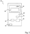
- the camera 40 is specifically suited to be incorporated in a mobile phone, since a mobile phone camera is particularly used for acquiring images in a quick and simple manner.
- the method may be implemented in any kind of digital camera.
- the camera 40 comprises a viewfinder 42 in which the view of the camera is imaged.
- the viewfinder 42 forms a part of a display 44 and shows a live image of the view of the camera.
- the display 44 is further arranged to guide the user in capturing combined images.
- the display 44 may show an animation of how the camera should be moved and the display 44 may also present a schematic representation of the previously recorded image to the present view of the camera.
- the camera 40 further comprises a vibrator 46, which may be activated and deactivated for guiding the user in movement of the camera.
- the camera 40 may also comprise a speaker 48 such that a sound signal may be emitted for guiding the user.
- the camera 40 also comprises a processor unit 50.
- the processor unit 50 compares the previously recorded image to the present view of the camera and decides whether the camera is directed towards an appropriate view for capturing a subsequent image.
- the processor unit 50 also processes all captured images in order to stitch the images to a large combined image.
- the captured images may temporarily be stored in a RAM memory 52 during the image-capturing process and while the images are stitched together.
- the combined image When the combined image has been created it may be stored in a permanent memory 54.
Description
- The present invention relates to a method for acquiring at least two digital images by means of a digital camera, wherein the digital images are to be stitched into a combined image.
- When using a digital camera to capture images of a landscape, an image with a wide field of view may often be desired. This may be artificially created by capturing a plurality of images which are then stitched together to create a large image of the landscape.
- A most effective result of the stitched image may be obtained by capturing images that are suitable for being stitched together. In this regard, the images should be captured with an appropriate overlap and a good alignment. An overlap is needed to enable the images to be seamlessly stitched together. Further, the final panoramic image is limited in the vertical direction by the top of the lowest image of the plurality of images forming the panorama, and the bottom of the highest image. Thus, a good alignment will enable the final panoramic image to be created with a maximum or near maximum vertical size.
- It is difficult to capture images optimally suited for creating a panoramic image even for an experienced photographer. In order to achieve adequate results, it may be required to use a tripod.
- Therefore, there is a need for aiding a user in taking images that are suited for forming a panoramic image. In
US 2005/0168594 , a method for guiding a user through the image-taking procedure for creating a panoramic photograph is disclosed. According to the method, an algorithm displays indicia that are overlaid and moved over a live image during the image-taking process to help align the subsequent image to be taken with the previously recorded image. - Thus, the display simultaneously shows to the user a part of the image that was previously recorded and a part of the image that will be recorded. This helps the user to correctly align and correlate the images to each other.
- Another method of helping users to acquire panoramic images is described in P. Baudisch, D. Tan, D. Steedly, E. Rudolph, M. Uyttendaele, C. Pal, and R. Szeliski, "Panoramic Viewfinder: Providing a Real-Time Preview to Help Users Avoid Flaws in Panoramic Pictures", Proceedings of OZCHI 2005. According to this method, a panoramic viewfinder is used, which simultaneously shows three different types of information to the user; (1) a preview shows the panorama in its current state of completion, (2) the viewfinder shows what the camera sees at the moment, and (3) the real-time cropping frame shows the extent the panorama will have after cropping if the user stopped shooting at this instant.
- However, panoramic images are often captured in a bright environment, which makes it hard to view an overlap of images and therefore the display is ineffective in helping the user in the image-taking process. Further, if a self-portrait is desired, the user is not able to see the viewfinder and is not helped at all.
- Therefore, an improved user interface for aiding a user in taking several images to be stitched together is desired.
-
US 2006/0050152 A1 relates to a method for stitching digital images together onboard a digital imaging device. A first image is captured and portions of said first image are retained in a viewfinder of the digital image device on the display with which a live image can be aligned by a user. -
EP 1 613 060 A1 relates to a method of capturing a sequence of images by an imaging device. After having captured and stored at least one image, a user is guided to move the imaging device so that an image that can be stitched to said at least one stored image can be captured. - It is an object of the invention to provide a method that aids a user in taking images to be stitched into a combined image. Therefore, a method according to claim 1 and an apparatus according to
claim 14 is provided. It is a specific object of the invention to provide such a method that is effective in bright environments and when a self-portrait is taken. - These and other objects of the invention, which may become apparent from the following description, are at least partly achieved by means of a method according to any of the independent claims. Specific embodiments are set out in the dependent claims.
- In the context of this application, the term "combined image" should be construed as an image that is formed from a combination of at least two captured images. The captured images may be formed into a panoramic image that is oblong and shows a wide angle of a scenery. However, the captured images may be related to each other in any way. For example, they may form a matrix of n times m images, where n and m are arbitrary numbers. Further, the combined image need not be rectangular. On the contrary, the captured images may be stitched together to form a combined image of an arbitrary shape.
- Thus, according to a first aspect, a method for acquiring at least two digital images by means of a digital camera, wherein the digital images are to be stitched into a combined image, comprises capturing a first digital image, wherein a first scenery is imaged; determining a relation between the first scenery and a second scenery being viewed by the digital camera, while said second scenery being viewed by the digital camera is changed; analysing the relation between the first scenery and the second scenery being viewed by the digital camera in order to identify an appropriate view to be captured by the digital camera in a second digital image for facilitating stitching of the first and second digital images; and indicating to the user that the camera is directed towards an appropriate view for capturing a second digital image, wherein said indicating comprises emitting a signal that is tactile for a user.
- By means of the method, the digital camera determines the relationship between the previously captured image and the image to be captured. Thus, the camera itself determines the view to be imaged in the image to be captured. The user is then guided by an indication from the digital camera that the camera is properly directed for capturing an image. Thus, guidance of a user for aiding in acquiring combined images may be accomplished in bright environments and even when a user is not able to see the viewfinder (such as when taking a self-portrait).
- The method deprives the user of the control of the capturing of the images since the second scenery to be imaged is determined by the camera. However, this enables the camera to guide the user in a more effective manner.
- The indication to the user that the camera is directed towards an appropriate view need not necessarily guide the user to an optimal view for capturing a second digital image. The indication may provide information to the user of how far away the present view is from an optimal view. The user may thus use this information to control capturing of a second digital image when the user finds it appropriate. Further, the indication may inform the user of a situation when the camera is being moved in a direction away from a suitable view of a second image. In this situation, an indication may be given that a second image is to be captured before the camera is moved so far away from the suitable view that the captured images are no longer suited to be stitched at all. Thus, the indication may force a second image to be captured, wherein the second image is not depicting a particularly suitable view for stitching, but the second image is depicting a view that is able to be stitched to the first image.
- The human body responds very quickly to the tactile sense. Therefore, by emitting any kind of message or signal that may be sensed by the user, the user may very quickly react to the signal.
- The tactile signal may be accomplished in different ways. It may be in form of a small electric impulse, a change in temperature or a sensed vibration.
- For example, the emitting may comprise activating a vibrator to inform a user of the relation between the first scenery and the second scenery. The vibrator may be activated during tracking when the digital camera is moved and be deactivated to indicate that the camera is directed towards an appropriate view for capturing an image. This implies that the user may be continuously guided in the movement of the camera. The guidance is not affected by a bright or noisy environment, since the user may sense the deactivation of the vibrator by means of his hand holding the camera. The user will then know that the camera has been properly directed.
- Of course, the vibrator may be used in other ways to communicate with the user. The vibrator may be used in the reverse manner, i.e. the vibrator being activated for a short period of time when the camera has been properly directed. The intensity of the vibrator may alternatively be varied in order to communicate to the user how far away the camera is from being directed towards an appropriate or an optimal view.
- According to a second aspect, a method for acquiring at least two digital images by means of a digital camera, wherein the digital images are to be stitched into a combined image, comprises capturing a first digital image, wherein a first scenery is imaged; determining a relation between the first scenery and a second scenery being viewed by the digital camera, while said second scenery being viewed by the digital camera is changed; analysing the relation between the first scenery and the second scenery being viewed by the digital camera in order to identify an appropriate view to be captured by the digital camera in a second digital image for facilitating stitching of the first and second digital images; and indicating to the user that the camera is directed towards an appropriate view for capturing a second digital image, wherein said indicating comprises emitting a sound signal.
- By means of the method, the digital camera determines the relationship between the previously captured image and the image to be captured. Thus, the camera itself determines the view to be imaged in the image to be captured. The user is then guided by an indication from the digital camera that the camera is properly directed for capturing an image. Thus, guidance of a user for aiding in acquiring combined images may be accomplished in bright environments and even when a user is not able to see the viewfinder (such as when taking a self-portrait).
- The method deprives the user of the control of the capturing of the images since the second scenery to be imaged is determined by the camera. However, this enables the camera to guide the user in a more effective manner.
- The indication to the user that the camera is directed towards an appropriate view need not necessarily guide the user to an optimal view for capturing a second digital image. The indication may provide information to the user of how far away the present view is from an optimal view. The user may thus use this information to control capturing of a second digital image when the user finds it appropriate. Further, the indication may inform the user of a situation when the camera is being moved in a direction away from a suitable view of a second image. In this situation, an indication may be given that a second image is to be captured before the camera is moved so far away from the suitable view that the captured images are no longer suited to be stitched at all. Thus, the indication may force a second image to be captured, wherein the second image is not depicting a particularly suitable view for stitching, but the second image is depicting a view that is able to be stitched to the first image.
- For example, the emitting of a sound signal may comprise emitting a sound signal to inform a user of the relation between the first scenery and the second scenery. The emitting of the sound signal may be activated during tracking when the digital camera is moved and be deactivated to indicate that the camera is directed towards an appropriate view for capturing an image. The user will then know that the camera has been properly directed. This implies that the user may be continuously guided in the movement of the camera and the guidance is not affected by a bright environment.
- Of course, the sound signal may be used in other ways to communicate with the user. The sound signal may e.g. be used in the reverse manner, i.e. the emitting of the sound signal is activated for a short period of time when the camera has been properly directed. The intensity of the sound signal may alternatively be varied in order to communicate to the user how far away the camera is from being directed towards an appropriate or an optimal view.
- The second scenery may change in different ways. The scenery may change by movements taking place in front of the camera. In such case, the camera may be held still, while the scenery in front of the camera is changing. Then, several images may be taken by a stationary camera. Movements in relation to a background may then be illustrated in the combined image. The combined image may thus be a combination of several images that are placed on top of each other.
- Alternatively, the second scenery may change by the camera being moved. The determining may comprise keeping track of a position of the first scenery in relation to the second scenery being viewed by the digital camera, while the digital camera is moved to change said second scenery being viewed by the digital camera. In this case, the camera is being moved and, thus, the scenery being viewed by the camera is changed. The relation between the first scenery and the changing second scenery is monitored in order to enable a second image to be captured that is suitable for stitching to the first image.
- According to one embodiment, keeping track of a position of the first scenery in relation to the second scenery comprises comparing images. This implies that movement of the camera is monitored by comparing views towards which the camera is being directed. This may be realized, for instance, by continuously comparing temporary small images being captured by the viewfinder. A comparison may be made to any of the previously captured temporary images in order to constantly update the relation between the second scenery and the first scenery.
- According to another embodiment, keeping track of a position of the first scenery in relation to the second scenery comprises sensing a change in direction of the digital camera. The sensing may be achieved e.g. by means of a gyroscope, that detects any rotation of the digital camera. Alternatively, the sensing may be achieved by means of a compass, whereby rotations in relation to the earth's magnetic field may be detected. With knowledge of a viewing angle of the digital camera, an allowed rotation of the digital camera may be set.
- The method may further comprise communicating information to the user related to the change of the second scenery. This implies that the camera may give the user information of the status of a movement of the camera and thereby guide the movement such that the camera may be directed towards an appropriate part of the scenery.
According to one embodiment, the communicating may comprise displaying a schematic representation of the relation between the first scenery and the second scenery being viewed by the digital camera. This enables a user to be guided in a bright environment when the details of the viewfinder are difficult to discern. - The method may further comprise capturing a second digital image when the camera is directed towards an appropriate view, said capturing being automatically performed by the digital camera.
- In this way, an automated method of acquiring a combined image is achieved. Thus, the user will not need to push the capture button during the acquiring of the second and subsequent images. This implies that the camera will not be moved out of position due to the capture button being pressed. Instead, the user may focus entirely on aiming the camera in a correct direction.
- Moreover, the communication of information related to the movement of the camera to the user may allow the user to temporarily stop moving the camera at various positions when it is indicated that an image is to be acquired. Thus, motion blur is prevented and high quality sharp images may be acquired.
- This method allows several images that are to form a combined image to be captured very quickly. The user simply pushes the capture button to start acquiring the images and then sweeps the camera over the scenery to be imaged. The user is continuously guided when to temporarily stop sweeping the camera to allow another image to be captured.
- This is a highly automated method that will help the user to acquire images for creation of a combined image. The user will not need to take any decisions regarding when to capture images. In fact, once the user has started the procedure to acquire a combined image, the user may merely follow instructions communicated by the camera. In particular, the user will not need to see the viewfinder of the camera and may thus acquire a self-portrait or a combined image in bright or dark environment.
- The indicating may comprise communicating information to the user that an image will be automatically captured in advance of the actual capture of the image. This implies that the user will be able to stop movement of the digital camera before the second digital image is captured. Thus, motion blur may effectively be eliminated.
- The automatic capture may be performed a predefined period of time after information is communicated to the user that a second image is about to be captured. Alternatively, the automatic capture may be performed in response to detection that the movement of the camera has been stopped.
- The analysing may use a predefined desired overlap between adjacent images for identifying an appropriate view. This overlap may be set to fit the optical set-up of the camera and, thus, optimal combined images may be obtained by using a programmed algorithm for acquiring images.
- According to an alternative, the analysing may comprise determining whether conditions prevail that are appropriate for capturing a second digital image. For example, the analysis may detect that the camera is hardly being moved. In such case, the conditions are such that a second image may appropriately be captured. Since the camera is only slightly moved, if moved at all, motion blur may be avoided. Thus, if the camera is aimed at a view that may be appropriate for stitching and these non-movement conditions of the camera prevail, a decision may be taken to capture a second digital image. As an alternative, the analysis may detect that the camera is directed towards a view being particularly suited for stitching to previously captured images. This may be detected as appropriate conditions for capturing a second digital image, even if the camera is being moved at the time. An indication may then be communicated to the user that an image will soon be captured allowing the user to stop the movement of the camera at the appropriate position. Thereafter, a second digital image is captured.
- The method may further comprise displaying an animation of desired movement of the digital camera, wherein the animation is synchronised with the actual movement of the digital camera. This animation gives the user an easy understanding of how to move the camera. For example, the animation may show to the user that the camera is merely to be rotated and that neither any linear movement of the camera nor any tilting movement of the camera is to be made if a panoramic image is to be captured.
- According to a third aspect, a method for acquiring at least two digital images by means of a digital camera, wherein the digital images are to be stitched into a combined image, comprises: capturing a first digital image, wherein a first scenery is imaged; allowing a user to move the digital camera to direct the camera towards a second scenery partly overlapping the first scenery; communicating to a user that a second digital image is about to be automatically captured; and automatically capturing a second digital image.
- The method aids the user in acquiring images for forming a combined image, wherein motion blur in the images is prevented. Since the user is informed that a digital image is to be captured before the image is actually captured, the user will be able to stop movement of the camera. The automatic capture of the second image implies that no motion blur may be formed due to the user pressing a capture button,
- Further, when several subsequent images are to be captured, the communication to the user may occur at regular intervals. This implies that the user may be aided in sweeping a scenery and capturing images appropriate for stitching. Since the user need not make any decisions regarding appropriate directions of the camera, the user may move the camera in a steady, uniform manner. This implies that the difference in viewing angle between adjacent images may be constant throughout sweeping of the scenery. Thereby, the user is aided by the camera to obtain images suitable for stitching into a combined image, even though no analysis is made regarding the relation between the imaged sceneries during capture of images.
- The communication to the user may be achieved in many different ways, as described above with reference to the first and second aspects.
- The automatic capture of the second digital image may be performed at a predetermined period of time after said communicating. The predetermined period of time may be any suitable time period allowing the user to stop movement of the camera before the second digital image is captured. This predetermined period of time may typically be less than a second.
- According to the invention, the method comprises detecting a stopped movement of the digital camera, wherein the automatic capturing of the second digital image is performed in response to detection of a stopped movement. This implies that it is positively ensured that the second digital image does not contain any motion blur.
- According to the invention, a method for acquiring at least two digital images by means of a digital camera, wherein the digital images are to be stitched into a combined image, comprises: capturing a first digital image, wherein a first scenery is imaged; allowing a user to move the digital camera to direct the camera towards a second scenery; detecting a stopped movement of the digital camera; and automatically capturing a second digital image in response to detection of a stopped movement.
- According to this aspect of the invention, the user controls the positioning of the camera when an image is captured. By stopping movement of the camera, the user will initiate capturing of an image. This implies that the images are captured without any motion blur. Further, since images are automatically captured in response to a detected stopped movement of the digital camera, the images may be very quickly captured. This allows the user to move the camera in a rapid manner and thereby the user may be able to move the camera in a steady, uniform manner. Also, the automatic capture of the second image implies that no motion blur may be formed due to the user pressing a capture button.
- The invention will now be described in further detail by way of example under reference to the accompanying drawings.
-
Fig. 1 is a flow chart of a method according to an embodiment of the invention. -
Fig. 2 is a schematic view of a digital camera to be used in the method. - Referring now to
Fig. 1 , a method of guiding a user in acquiring digital images to be stitched into a combined image will be described. - A user initiates the acquiring of the digital images by pressing a capture button in a combined image capturing mode of the digital camera,
step 10. The camera is thus activated to capture a first image of a first scenery viewed by the digital camera,step 12. Further, the camera is activated to guide the user in directing the camera towards appropriate views of further sceneries for forming the combined image. - The camera records temporary images of the scenery being viewed by the camera as the camera is moved,
step 14. These temporary images are displayed on the viewfinder. Further, the previously recorded image is compared to the temporary images and a position of the scenery being imaged in the previously recorded image is tracked,step 16. The camera analyses the relation between the scenery that has been imaged in the previously recorded digital image and the scenery being viewed,step 18. Based on this analysis, the camera decides whether the camera is directed towards an appropriate view for capturing a subsequent image. When the camera is directed towards an appropriate view, the camera automatically captures a digital image,step 20. - The temporary images being continuously captured may be compared to each other for continuously updating how the camera has been moved. This implies that only small images are being compared to each other keeping computation complexity of the tracking relatively low. The position of the scenery being imaged in the previously recorded image may be modelled by a first temporary image that is registered in the viewfinder immediately after capturing an image.
- A predefined overlap may be programmed in the camera. Thus, the camera analyses the overlap of the scenery that has been imaged with the scenery being viewed in order to determine the overlap. During movement of the camera, the overlap continuously decreases. When the overlap reaches the predefined level, the analysis decides that the camera is directed towards an appropriate view.
- The predefined overlap allows the camera to be appropriately programmed to suit the optical set-up of the camera. However, the user may be allowed to change the predefined overlap before capturing a combined image.
- The tracking may be performed in real time, since the tracking uses the image of the viewfinder, which is very small. Tracking may be performed in any suitable way to compare and match the previously recorded image to the temporary image in the viewfinder, as will be appreciated by those skilled in the art. For example, an optical flow algorithm or a two-dimensional correlation algorithm may be used for comparing the images to each other in order to determine whether the images correlate in such a way that it is appropriate to capture another image.
- As an alternative to using a predefined overlap, the analysis may comprise determining whether conditions prevail that are appropriate for capturing a second digital image. For example, the analysis may detect that the camera is hardly being moved. In such case, the conditions are such that a second image may appropriately be captured. Since the camera is only slightly moved, if moved at all, motion blur may be avoided. Thus, if the camera is aimed at a view that may be appropriate for stitching and these non-movement conditions of the camera prevail, a decision may be taken to capture a second digital image.
- As a further alternative, the analysis may detect that the camera is directed towards a view being particularly suited for stitching to previously captured images. This may be detected as appropriate conditions for capturing a second digital image, even if the camera is being moved at the time. An indication may then be communicated to the user that an image will soon be captured allowing the user to stop the movement of the camera at the appropriate position. Thereafter, a second digital image is captured.
- The camera is arranged to capture the subsequent image automatically when the analysis decides that the camera is directed towards an appropriate view. This implies that the user will not need to give any further input to the camera, such as pressing a capture button. Thus, the user may focus on directing the camera correctly and, in particular, no movement of the camera out of position will occur due to the user shaking when the button is pressed.
- However, according to an alternative example, the user may initiate the capturing of each image by pressing a button when the user has been guided by the camera to direct the camera towards the appropriate view.
- During the movement of the camera for capturing images of different parts of the scenery, the camera continuously guides the user in the movement. Thus, simultaneously with steps 14-20, the camera informs the user of how to move the camera. The camera displays an animation of how the user should move the camera,
step 22. Further, the camera indicates when the movement should be temporarily stopped for acquiring an image,step 24. - The camera may indicate when the movement should be temporarily stopped in many different ways. According to a first alternative, the camera activates a vibrator while the camera is moved. When the camera is properly directed for capturing an image, the vibrator is deactivated. According to a second alternative, the camera activates a vibrator when the camera is properly directed for capturing an image.
- Thus, a user will sense the vibrator being activated with his hand holding the camera. This implies that no visual or audible communication with the user is needed, which may be advantageous when capturing a combined image in a bright or dark environment or in a noisy environment. Further, the physical response to a tactile impulse is very quick and, therefore, the user may quickly react on the sensed communication. The vibrator may be used in many different ways to communicate with the user. For example, the intensity of the vibration may be increased as an appropriate view is approached or, alternatively, the intensity of the vibration may be decreased as an appropriate view is approached. Thus, the user may get feedback on how far away the camera is from being directed towards an appropriate view.
- According to a third alternative, the camera emits a sound signal when the camera is properly directed for capturing an image. According to a fourth alternative, the camera emits a sound signal while the camera is moved. When,the camera is properly directed for capturing an image, the sound signal is deactivated.
- Thus, a user will hear the sound signal being activated. This implies that no visual communication with the user is needed, which may be advantageous when capturing a combined image in a bright or dark environment.
- The sound signal may be used in many different ways to communicate with the user. For example, the volume of the sound signal may be increased as an appropriate view is approached or, alternatively, the volume of the sound signal may be decreased as an appropriate view is approached. Thus, the user may get feedback on how far away the camera is from being directed towards an appropriate view.
- The above mentioned alternatives are especially advantageous in conditions when the user has trouble seeing visual indications. For example, this facilitates capturing a panoramic self-portrait or other combined images when the viewfinder may not be watched.
- According to a further alternative, the camera displays a schematic view of the relation of the scenery imaged in the previously recorded image to the scenery being viewed. The previously recorded image may be represented by a first rectangle and the scenery being viewed may be represented by a second rectangle being moved relative the first rectangle. A third rectangle indicating the desired position of the subsequent image to be captured may also be displayed. Thus, the user may continuously see how the part of the scenery being viewed approaches the appropriate view for capturing the subsequent image. This gives the user continuous feedback of how close the camera view is to the subsequent desired view and may thus improve the ability of the user to aim the camera correctly.
- Two or more of the above alternatives may be used in conjunction with each other. In such manner, the guidance of the user may be further improved.
- When the entire scenery to be imaged in the combined image has been swept, the image-capturing process is stopped,
step 26. The user may stop the process by pushing a button or stopping the movement of the camera. Alternatively, the process may be stopped when a predetermined number of images to be stitched together have been captured. - When all needed images have been captured, the images are stitched together to form one large combined image,
step 28. The captured images may be processed in order to facilitate matching. For instance, a cylindrical projection and lens correction of the images may be performed. Then the captured and processed images are analysed in order to match them together appropriately. This may be performed using any suitable matching algorithm as will be appreciated by those skilled in the art. - According to an alternative example, indications may be given to the user at regular time intervals that an image is to be captured. This implies that no tracking of the position of the scenery being imaged in the previously recorded image is performed. Further, no analysis whether the camera is directed towards an appropriate view is performed. The user is merely aided to stop movement of the camera at regular time intervals for allowing the camera to capture images without motion blur. Thereafter, the captured images may be stitched together into a combined image. The stitching of these images may require more computations, since no control that an acceptable overlap of the images was present occurred during capturing of the images. However, the regular timing of the capturing of the images makes it likely that a good result of stitching may be achieved.
- According to the invention, the user will further control when images are to be captured. A processor is arranged to detect when a movement of the camera has been stopped. In response to this non-movement, an image will be captured. Thus, there will be no motion blur in the captured image. By stopping movement of the camera at appropriate positions, the user may force the camera to capture images at these positions. The capturing of images is performed automatically as detection of non-movement is made.
- The non-movement may be detected by means of comparing temporary images captured by the viewfinder to each other. When there is no or insignificant difference between two subsequent temporary images, this may be interpreted as the camera not being moved. In order to make the detection of non-movement more reliable, it may be required that no or merely insignificant difference should exist between three or more subsequent temporary images.
- Referring now to
Fig. 2 , a camera will be described that may be used in capturing a combined image according to the method described above. Thecamera 40 is specifically suited to be incorporated in a mobile phone, since a mobile phone camera is particularly used for acquiring images in a quick and simple manner. However, the method may be implemented in any kind of digital camera. Thecamera 40 comprises aviewfinder 42 in which the view of the camera is imaged. Theviewfinder 42 forms a part of adisplay 44 and shows a live image of the view of the camera. Thedisplay 44 is further arranged to guide the user in capturing combined images. Thedisplay 44 may show an animation of how the camera should be moved and thedisplay 44 may also present a schematic representation of the previously recorded image to the present view of the camera. - The
camera 40 further comprises avibrator 46, which may be activated and deactivated for guiding the user in movement of the camera. Thecamera 40 may also comprise aspeaker 48 such that a sound signal may be emitted for guiding the user. - The
camera 40 also comprises aprocessor unit 50. Theprocessor unit 50 compares the previously recorded image to the present view of the camera and decides whether the camera is directed towards an appropriate view for capturing a subsequent image. Theprocessor unit 50 also processes all captured images in order to stitch the images to a large combined image. The captured images may temporarily be stored in aRAM memory 52 during the image-capturing process and while the images are stitched together. When the combined image has been created it may be stored in apermanent memory 54. - It should be emphasized that the preferred embodiment described herein is in no way limiting and that many alternative embodiments are possible within the scope of protection defined by the appended claims.
Claims (14)
- A method comprising:after capturing (12) a first digital image by a digital camera (40), identifying an appropriate view to be captured by the digital camera as a second digital image for facilitating stitching of the first digital image and the second digital image into a combined image;indicating to a user how to move the digital camera so that the digital camera is directed towards an appropriate view for capturing the second digital image;indicating (24) to a user that movement of the digital camera should be stopped when the digital camera is directed towards the appropriate view for capturing the second digital image so that the digital camera can capture the second digital image of the appropriate view; andcapturing (20) the second digital image when the digital camera is directed towards the appropriate view, said capturing being automatically performed by the digital camera and wherein said capturing is performed in response to a detection of stopped movement or non-movement of the digital camera when the digital camera is directed towards the appropriate view.
- The method according to claim 1, wherein indicating to a user how to move the digital camera (40) so that the digital camera is directed towards an appropriate view for capturing the second digital image, comprises displaying to a user how to move the digital camera so that the digital camera is directed towards an appropriate view for capturing the second digital image.
- The method according to claim 1 or 2, wherein indicating to a user how to move the digital camera (40) so that the digital camera is directed towards an appropriate view for capturing the second digital image, comprises providing feedback on how far away the digital camera is from being directed towards the appropriate view.
- The method according to any preceding claim, wherein indicating to a user how to move the digital camera (40) so that the digital camera is directed towards an appropriate view for capturing the second digital image, comprises displaying information so that a user has feedback of how close the view to which the digital camera is directed towards is to the appropriate view.
- The method according to any preceding claim, wherein indicating to a user how to move the digital camera (40) so that the camera is directed towards an appropriate view for capturing the second digital image, comprises displaying a first marker positioned in dependence upon a view to which the digital camera is currently directed and displaying a second marker positioned in dependence upon the appropriate view, wherein the first marker approaching the second marker as the digital camera is moved indicates to a user that the view to which the digital camera is directed approaches the appropriate view.
- The method according to any preceding claim, wherein indicating to a user how to move the digital camera (40) so that the digital camera is directed towards an appropriate view for capturing the second digital image, comprises displaying information so that a user can continuously see how the view to which the digital camera is currently directed approaches the appropriate view.
- The method according to any preceding claim, comprising displaying an indication to a user when the digital camera (40) is being moved in a direction away from a suitable view.
- The method according to any preceding claim, comprising:indicating to a user that movement of the digital camera (40) should be stopped at various positions so that the digital camera can capture multiple digital images; andstitching (28) together the multiple second digital images to form a combined image.
- The method according to any preceding claim, further comprising:determining a relation between a first scenery of the captured first digital image and a second scenery being viewed by the digital camera (40); andwhile said second scenery being viewed by the digital camera is changed, analysing (18) the relation between the first scenery and the second scenery being viewed by the digital camera in order to identify an appropriate view to be automatically captured by the digital camera as the second digital image for facilitating stitching of the first and second digital images into a combined image.
- The method according to claim 9, wherein said analysing uses a predefined desired overlap between adjacent images for identifying an appropriate view.
- The method according to claim 9 or 10, wherein said determining comprises keeping track of a position of the first scenery in relation to the second scenery being viewed by the digital camera, while the digital camera (40) is moved to change said second scenery being viewed by the digital camera, wherein said keeping track of a position of the first scenery in relation to the second scenery comprises comparing images or sensing a change in direction of the digital camera.
- The method according to any preceding claim, further comprising communicating information to the user related to a change of a second scenery being viewed by the digital camera (40), wherein said communicating comprises displaying a schematic representation of the relation between the first scenery and the second scenery being viewed by the digital camera.
- The method according to any preceding claim, wherein indicating to a user that movement of the digital camera (40) should be stopped so that the digital camera can capture the second digital image of the appropriate view comprises communicating information to the user that an image will be automatically captured in advance of the actual capture of the image.
- An apparatus comprising:at least one processor (50); andat least one memory (52, 54),the at least one processor and memory being configured to cause the apparatus at least to performafter capturing a first digital image by a digital camera (40), identifying an appropriate view to be captured by the digital camera as a second digital image for facilitating stitching of the first digital image and the second digital image into a combined image;indicating to a user how to move the digital camera so that the digital camera is directed towards an appropriate view for capturing the second digital image;indicating (24) to a user that movement of the digital camera should be stopped when the digital camera is directed towards the appropriate view for capturing the second digital image so that the digital camera can capture the second digital image of the appropriate view; andcapturing (20) the second digital image when the digital camera is directed towards the appropriate view, said capturing being automatically performed by the digital camera and wherein said capturing is performed in response to a detection of stopped movement or non-movement of the digital camera when the digital camera is directed towards the appropriate view.
Applications Claiming Priority (3)
| Application Number | Priority Date | Filing Date | Title |
|---|---|---|---|
| SE0601577A SE532236C2 (en) | 2006-07-19 | 2006-07-19 | Method in connection with taking digital pictures |
| EP07748329.5A EP2041620B1 (en) | 2006-07-19 | 2007-07-11 | A method in relation to acquiring panoramic images |
| PCT/SE2007/000680 WO2008010762A1 (en) | 2006-07-19 | 2007-07-11 | A method in relation to acquiring digital images |
Related Parent Applications (2)
| Application Number | Title | Priority Date | Filing Date |
|---|---|---|---|
| EP07748329.5A Division EP2041620B1 (en) | 2006-07-19 | 2007-07-11 | A method in relation to acquiring panoramic images |
| EP07748329.5A Division-Into EP2041620B1 (en) | 2006-07-19 | 2007-07-11 | A method in relation to acquiring panoramic images |
Publications (2)
| Publication Number | Publication Date |
|---|---|
| EP3287844A1 EP3287844A1 (en) | 2018-02-28 |
| EP3287844B1 true EP3287844B1 (en) | 2021-06-23 |
Family
ID=38957023
Family Applications (2)
| Application Number | Title | Priority Date | Filing Date |
|---|---|---|---|
| EP17184995.3A Active EP3287844B1 (en) | 2006-07-19 | 2007-07-11 | A method in relation to acquiring digital images |
| EP07748329.5A Active EP2041620B1 (en) | 2006-07-19 | 2007-07-11 | A method in relation to acquiring panoramic images |
Family Applications After (1)
| Application Number | Title | Priority Date | Filing Date |
|---|---|---|---|
| EP07748329.5A Active EP2041620B1 (en) | 2006-07-19 | 2007-07-11 | A method in relation to acquiring panoramic images |
Country Status (7)
| Country | Link |
|---|---|
| US (2) | US7920161B2 (en) |
| EP (2) | EP3287844B1 (en) |
| JP (1) | JP2009544216A (en) |
| KR (1) | KR101237673B1 (en) |
| CN (2) | CN101490617A (en) |
| SE (1) | SE532236C2 (en) |
| WO (1) | WO2008010762A1 (en) |
Families Citing this family (29)
| Publication number | Priority date | Publication date | Assignee | Title |
|---|---|---|---|---|
| US7292261B1 (en) * | 1999-08-20 | 2007-11-06 | Patrick Teo | Virtual reality camera |
| WO2009093635A1 (en) * | 2008-01-22 | 2009-07-30 | Nikon Corporation | Lens tube, method of adjusting lens tube, method of manufacturing lens tube and imaging device |
| TW200937109A (en) * | 2008-02-22 | 2009-09-01 | Asia Optical Co Inc | Image pickup methods and image pickup systems |
| US8300117B2 (en) * | 2008-03-28 | 2012-10-30 | Fuji Xerox Co., Ltd. | System and method for exposing video-taking heuristics at point of capture |
| FR2942890A1 (en) * | 2009-03-05 | 2010-09-10 | Thomson Licensing | METHOD FOR CREATING AN ANIMATED SUITE OF PHOTOGRAPHS, AND APPARATUS FOR CARRYING OUT THE METHOD |
| SG166684A1 (en) * | 2009-05-11 | 2010-12-29 | Creative Tech Ltd | A multimodal camera and a method for selecting an operation mode of a camera |
| JP5383576B2 (en) * | 2010-03-31 | 2014-01-08 | 富士フイルム株式会社 | Imaging apparatus, imaging method, and program |
| CN101872113B (en) * | 2010-06-07 | 2014-03-19 | 中兴通讯股份有限公司 | Method and device for shooting panoramic photo |
| US8488040B2 (en) * | 2010-06-18 | 2013-07-16 | Microsoft Corporation | Mobile and server-side computational photography |
| JP5907660B2 (en) * | 2011-02-28 | 2016-04-26 | オリンパス株式会社 | Imaging device |
| KR101784176B1 (en) | 2011-05-25 | 2017-10-12 | 삼성전자주식회사 | Image photographing device and control method thereof |
| JP2013009106A (en) * | 2011-06-23 | 2013-01-10 | Nikon Corp | Imaging apparatus |
| EP2726937B1 (en) | 2011-06-30 | 2019-01-23 | Nokia Technologies Oy | Method, apparatus and computer program product for generating panorama images |
| US9690458B2 (en) | 2012-09-10 | 2017-06-27 | Mediatek Inc. | Image viewing method for displaying portion of selected image based on user interaction input and related image viewing system and machine readable medium |
| US8773502B2 (en) * | 2012-10-29 | 2014-07-08 | Google Inc. | Smart targets facilitating the capture of contiguous images |
| KR20140090318A (en) * | 2013-01-07 | 2014-07-17 | 삼성전자주식회사 | Supporting Method For Operating a Camera based on a Haptic function and Electronic Device supporting the same |
| JP5955348B2 (en) * | 2013-05-22 | 2016-07-20 | 株式会社テレパシーホールディングス | Wearable device having privacy protection function of captured image, control method thereof, and image sharing system |
| FR3007172B1 (en) * | 2013-06-12 | 2020-12-18 | Renault Sas | METHOD AND SYSTEM FOR IDENTIFYING A DAMAGE CAUSED TO A VEHICLE |
| US10474921B2 (en) | 2013-06-14 | 2019-11-12 | Qualcomm Incorporated | Tracker assisted image capture |
| EP3089101A1 (en) | 2013-12-03 | 2016-11-02 | Dacuda AG | User feedback for real-time checking and improving quality of scanned image |
| KR101946437B1 (en) | 2013-12-13 | 2019-02-11 | 후아웨이 디바이스 컴퍼니 리미티드 | Method and terminal for acquiring panoramic image |
| WO2015104236A1 (en) * | 2014-01-07 | 2015-07-16 | Dacuda Ag | Adaptive camera control for reducing motion blur during real-time image capture |
| CN105472232B (en) * | 2014-09-05 | 2018-10-19 | 宏达国际电子股份有限公司 | Image acquisition method and electronic device |
| US9986155B2 (en) | 2014-09-05 | 2018-05-29 | Htc Corporation | Image capturing method, panorama image generating method and electronic apparatus |
| WO2017042708A1 (en) * | 2015-09-09 | 2017-03-16 | Couponizer Ltd | Method and system for photographing long text subjects that extend beyond borders of a viewfinder |
| KR101905580B1 (en) * | 2016-02-17 | 2018-10-11 | 한국전자통신연구원 | Method and system for reproducing situation using mobile device having image shooting function |
| CN106851117B (en) | 2017-03-31 | 2020-01-31 | 联想(北京)有限公司 | method for obtaining panoramic photo and electronic equipment |
| US10194078B2 (en) * | 2017-06-09 | 2019-01-29 | Immersion Corporation | Haptic enabled device with multi-image capturing abilities |
| US11501465B2 (en) | 2018-05-07 | 2022-11-15 | Within Unlimited, Inc. | Time-lapse stereo macro photography systems and methods and stereo time-lapse video made with same |
Family Cites Families (24)
| Publication number | Priority date | Publication date | Assignee | Title |
|---|---|---|---|---|
| EP0878963A1 (en) * | 1992-10-09 | 1998-11-18 | Sony Corporation | Producing and recording images |
| JP3931393B2 (en) * | 1997-09-04 | 2007-06-13 | ソニー株式会社 | Camera-integrated video recorder and photographing method |
| US6466701B1 (en) * | 1997-09-10 | 2002-10-15 | Ricoh Company, Ltd. | System and method for displaying an image indicating a positional relation between partially overlapping images |
| US6552744B2 (en) * | 1997-09-26 | 2003-04-22 | Roxio, Inc. | Virtual reality camera |
| US6304284B1 (en) * | 1998-03-31 | 2001-10-16 | Intel Corporation | Method of and apparatus for creating panoramic or surround images using a motion sensor equipped camera |
| JP4208113B2 (en) * | 2000-04-19 | 2009-01-14 | 富士フイルム株式会社 | Album creating method and apparatus, and recording medium |
| US6930703B1 (en) * | 2000-04-29 | 2005-08-16 | Hewlett-Packard Development Company, L.P. | Method and apparatus for automatically capturing a plurality of images during a pan |
| AU2003246268A1 (en) * | 2002-08-09 | 2004-02-25 | Sharp Kabushiki Kaisha | Image combination device, image combination method, image combination program, and recording medium containing the image combination program |
| US20040174434A1 (en) * | 2002-12-18 | 2004-09-09 | Walker Jay S. | Systems and methods for suggesting meta-information to a camera user |
| US20040189849A1 (en) * | 2003-03-31 | 2004-09-30 | Hofer Gregory V. | Panoramic sequence guide |
| US20040239767A1 (en) * | 2003-05-29 | 2004-12-02 | Stavely Donald J. | Systems and methods for providing tactile feedback |
| JP2005117296A (en) * | 2003-10-07 | 2005-04-28 | Matsushita Electric Ind Co Ltd | Apparatus and method for assisting search |
| US7656429B2 (en) * | 2004-02-04 | 2010-02-02 | Hewlett-Packard Development Company, L.P. | Digital camera and method for in creating still panoramas and composite photographs |
| JP5055686B2 (en) * | 2004-05-13 | 2012-10-24 | ソニー株式会社 | Imaging system, imaging apparatus, and imaging method |
| BRPI0512824A (en) * | 2004-07-02 | 2008-04-22 | Sony Ericsson Mobile Comm Ab | method for capturing an image sequence by an imaging device and storing the images in a digital format; and, imaging device for capturing an image sequence |
| EP1613060A1 (en) * | 2004-07-02 | 2006-01-04 | Sony Ericsson Mobile Communications AB | Capturing a sequence of images |
| US7375745B2 (en) * | 2004-09-03 | 2008-05-20 | Seiko Epson Corporation | Method for digital image stitching and apparatus for performing the same |
| US7646400B2 (en) * | 2005-02-11 | 2010-01-12 | Creative Technology Ltd | Method and apparatus for forming a panoramic image |
| US7881968B2 (en) * | 2005-04-15 | 2011-02-01 | David Clifford R | Interactive image activation and distribution system and associated methods |
| US7424218B2 (en) * | 2005-07-28 | 2008-09-09 | Microsoft Corporation | Real-time preview for panoramic images |
| GB2428927A (en) * | 2005-08-05 | 2007-02-07 | Hewlett Packard Development Co | Accurate positioning of a time lapse camera |
| US20070081081A1 (en) * | 2005-10-07 | 2007-04-12 | Cheng Brett A | Automated multi-frame image capture for panorama stitching using motion sensor |
| CN1750593A (en) * | 2005-10-13 | 2006-03-22 | 上海交通大学 | Digital camera with image split function |
| US7715831B2 (en) * | 2006-03-24 | 2010-05-11 | Sony Ericssson Mobile Communications, Ab | Methods, systems, and devices for detecting and indicating loss of proximity between mobile devices |
-
2006
- 2006-07-19 SE SE0601577A patent/SE532236C2/en unknown
- 2006-12-06 US US11/634,264 patent/US7920161B2/en active Active
-
2007
- 2007-07-11 EP EP17184995.3A patent/EP3287844B1/en active Active
- 2007-07-11 JP JP2009520706A patent/JP2009544216A/en active Pending
- 2007-07-11 KR KR1020097000658A patent/KR101237673B1/en active IP Right Grant
- 2007-07-11 EP EP07748329.5A patent/EP2041620B1/en active Active
- 2007-07-11 CN CNA2007800270719A patent/CN101490617A/en active Pending
- 2007-07-11 WO PCT/SE2007/000680 patent/WO2008010762A1/en active Application Filing
- 2007-07-11 CN CN2013101326687A patent/CN103227903A/en active Pending
-
2010
- 2010-08-20 US US12/805,850 patent/US20110050960A1/en not_active Abandoned
Non-Patent Citations (1)
| Title |
|---|
| None * |
Also Published As
| Publication number | Publication date |
|---|---|
| EP3287844A1 (en) | 2018-02-28 |
| EP2041620A1 (en) | 2009-04-01 |
| JP2009544216A (en) | 2009-12-10 |
| EP2041620A4 (en) | 2011-04-27 |
| KR20090031725A (en) | 2009-03-27 |
| US7920161B2 (en) | 2011-04-05 |
| EP2041620B1 (en) | 2017-09-13 |
| SE532236C2 (en) | 2009-11-17 |
| WO2008010762A1 (en) | 2008-01-24 |
| CN101490617A (en) | 2009-07-22 |
| CN103227903A (en) | 2013-07-31 |
| KR101237673B1 (en) | 2013-02-26 |
| US20110050960A1 (en) | 2011-03-03 |
| SE0601577L (en) | 2008-01-20 |
| US20080018748A1 (en) | 2008-01-24 |
Similar Documents
| Publication | Publication Date | Title |
|---|---|---|
| EP3287844B1 (en) | A method in relation to acquiring digital images | |
| US20200236281A1 (en) | Imaging apparatus, imaging method, and program | |
| JP3989523B2 (en) | Automatic photographing method and apparatus | |
| US8265474B2 (en) | Autofocus system | |
| EP2563009B1 (en) | Method and electric device for taking panoramic photograph | |
| JP4218720B2 (en) | IMAGING DEVICE, IMAGING DEVICE CONTROL METHOD, AND COMPUTER PROGRAM | |
| JP5865388B2 (en) | Image generating apparatus and image generating method | |
| EP2993894B1 (en) | Image capturing method and electronic apparatus | |
| EP1613060A1 (en) | Capturing a sequence of images | |
| US20080080846A1 (en) | Selecting autofocus area in an image | |
| JP2010177741A (en) | Image capturing apparatus | |
| JP2007329784A (en) | Imaging apparatus, method for controlling the same, and computer program | |
| JPWO2013069050A1 (en) | Image generating apparatus and image generating method | |
| KR20090065914A (en) | Method for photographing panorama picture in automation | |
| KR20120038451A (en) | Control device, control method, program, and control system | |
| WO2006118563A1 (en) | Method and device for consistent region of interest | |
| JP2005184266A (en) | Imaging device | |
| JP6450879B2 (en) | Recording apparatus, recording method, and recording program | |
| JP6550506B2 (en) | Recording apparatus, recording method and recording program | |
| JP6362735B2 (en) | IMAGING DEVICE, IMAGING DEVICE CONTROL METHOD AND CONTROL PROGRAM | |
| JP6375114B2 (en) | Image reproducing apparatus and method for controlling image reproducing apparatus | |
| KR20200005440A (en) | Electronic device for capturing media using a bendable display and method thereof | |
| JP6169963B2 (en) | IMAGING DEVICE AND IMAGING DEVICE CONTROL METHOD | |
| JP2018133617A (en) | Photographing apparatus, control method executed by the same, program, and storage medium | |
| JP2001251548A (en) | Image input device |
Legal Events
| Date | Code | Title | Description |
|---|---|---|---|
| PUAI | Public reference made under article 153(3) epc to a published international application that has entered the european phase |
Free format text: ORIGINAL CODE: 0009012 |
|
| STAA | Information on the status of an ep patent application or granted ep patent |
Free format text: STATUS: THE APPLICATION HAS BEEN PUBLISHED |
|
| AC | Divisional application: reference to earlier application |
Ref document number: 2041620 Country of ref document: EP Kind code of ref document: P |
|
| AK | Designated contracting states |
Kind code of ref document: A1 Designated state(s): AT BE BG CH CY CZ DE DK EE ES FI FR GB GR HU IE IS IT LI LT LU LV MC MT NL PL PT RO SE SI SK TR |
|
| STAA | Information on the status of an ep patent application or granted ep patent |
Free format text: STATUS: REQUEST FOR EXAMINATION WAS MADE |
|
| 17P | Request for examination filed |
Effective date: 20180828 |
|
| RBV | Designated contracting states (corrected) |
Designated state(s): AT BE BG CH CY CZ DE DK EE ES FI FR GB GR HU IE IS IT LI LT LU LV MC MT NL PL PT RO SE SI SK TR |
|
| RAP1 | Party data changed (applicant data changed or rights of an application transferred) |
Owner name: NOKIA TECHNOLOGIES OY |
|
| STAA | Information on the status of an ep patent application or granted ep patent |
Free format text: STATUS: EXAMINATION IS IN PROGRESS |
|
| 17Q | First examination report despatched |
Effective date: 20190717 |
|
| RAP1 | Party data changed (applicant data changed or rights of an application transferred) |
Owner name: NOKIA TECHNOLOGIES OY |
|
| GRAP | Despatch of communication of intention to grant a patent |
Free format text: ORIGINAL CODE: EPIDOSNIGR1 |
|
| STAA | Information on the status of an ep patent application or granted ep patent |
Free format text: STATUS: GRANT OF PATENT IS INTENDED |
|
| GRAJ | Information related to disapproval of communication of intention to grant by the applicant or resumption of examination proceedings by the epo deleted |
Free format text: ORIGINAL CODE: EPIDOSDIGR1 |
|
| INTG | Intention to grant announced |
Effective date: 20201217 |
|
| GRAP | Despatch of communication of intention to grant a patent |
Free format text: ORIGINAL CODE: EPIDOSNIGR1 |
|
| STAA | Information on the status of an ep patent application or granted ep patent |
Free format text: STATUS: GRANT OF PATENT IS INTENDED |
|
| INTG | Intention to grant announced |
Effective date: 20201217 |
|
| INTG | Intention to grant announced |
Effective date: 20210115 |
|
| GRAS | Grant fee paid |
Free format text: ORIGINAL CODE: EPIDOSNIGR3 |
|
| GRAA | (expected) grant |
Free format text: ORIGINAL CODE: 0009210 |
|
| STAA | Information on the status of an ep patent application or granted ep patent |
Free format text: STATUS: THE PATENT HAS BEEN GRANTED |
|
| AC | Divisional application: reference to earlier application |
Ref document number: 2041620 Country of ref document: EP Kind code of ref document: P |
|
| AK | Designated contracting states |
Kind code of ref document: B1 Designated state(s): AT BE BG CH CY CZ DE DK EE ES FI FR GB GR HU IE IS IT LI LT LU LV MC MT NL PL PT RO SE SI SK TR |
|
| REG | Reference to a national code |
Ref country code: GB Ref legal event code: FG4D |
|
| REG | Reference to a national code |
Ref country code: CH Ref legal event code: EP |
|
| REG | Reference to a national code |
Ref country code: DE Ref legal event code: R096 Ref document number: 602007061197 Country of ref document: DE Ref country code: AT Ref legal event code: REF Ref document number: 1404804 Country of ref document: AT Kind code of ref document: T Effective date: 20210715 |
|
| REG | Reference to a national code |
Ref country code: IE Ref legal event code: FG4D |
|
| REG | Reference to a national code |
Ref country code: LT Ref legal event code: MG9D |
|
| PG25 | Lapsed in a contracting state [announced via postgrant information from national office to epo] |
Ref country code: BG Free format text: LAPSE BECAUSE OF FAILURE TO SUBMIT A TRANSLATION OF THE DESCRIPTION OR TO PAY THE FEE WITHIN THE PRESCRIBED TIME-LIMIT Effective date: 20210923 Ref country code: FI Free format text: LAPSE BECAUSE OF FAILURE TO SUBMIT A TRANSLATION OF THE DESCRIPTION OR TO PAY THE FEE WITHIN THE PRESCRIBED TIME-LIMIT Effective date: 20210623 Ref country code: LT Free format text: LAPSE BECAUSE OF FAILURE TO SUBMIT A TRANSLATION OF THE DESCRIPTION OR TO PAY THE FEE WITHIN THE PRESCRIBED TIME-LIMIT Effective date: 20210623 |
|
| REG | Reference to a national code |
Ref country code: AT Ref legal event code: MK05 Ref document number: 1404804 Country of ref document: AT Kind code of ref document: T Effective date: 20210623 |
|
| PG25 | Lapsed in a contracting state [announced via postgrant information from national office to epo] |
Ref country code: SE Free format text: LAPSE BECAUSE OF FAILURE TO SUBMIT A TRANSLATION OF THE DESCRIPTION OR TO PAY THE FEE WITHIN THE PRESCRIBED TIME-LIMIT Effective date: 20210623 Ref country code: LV Free format text: LAPSE BECAUSE OF FAILURE TO SUBMIT A TRANSLATION OF THE DESCRIPTION OR TO PAY THE FEE WITHIN THE PRESCRIBED TIME-LIMIT Effective date: 20210623 Ref country code: GR Free format text: LAPSE BECAUSE OF FAILURE TO SUBMIT A TRANSLATION OF THE DESCRIPTION OR TO PAY THE FEE WITHIN THE PRESCRIBED TIME-LIMIT Effective date: 20210924 |
|
| REG | Reference to a national code |
Ref country code: NL Ref legal event code: MP Effective date: 20210623 |
|
| PG25 | Lapsed in a contracting state [announced via postgrant information from national office to epo] |
Ref country code: SK Free format text: LAPSE BECAUSE OF FAILURE TO SUBMIT A TRANSLATION OF THE DESCRIPTION OR TO PAY THE FEE WITHIN THE PRESCRIBED TIME-LIMIT Effective date: 20210623 Ref country code: RO Free format text: LAPSE BECAUSE OF FAILURE TO SUBMIT A TRANSLATION OF THE DESCRIPTION OR TO PAY THE FEE WITHIN THE PRESCRIBED TIME-LIMIT Effective date: 20210623 Ref country code: PT Free format text: LAPSE BECAUSE OF FAILURE TO SUBMIT A TRANSLATION OF THE DESCRIPTION OR TO PAY THE FEE WITHIN THE PRESCRIBED TIME-LIMIT Effective date: 20211025 Ref country code: NL Free format text: LAPSE BECAUSE OF FAILURE TO SUBMIT A TRANSLATION OF THE DESCRIPTION OR TO PAY THE FEE WITHIN THE PRESCRIBED TIME-LIMIT Effective date: 20210623 Ref country code: ES Free format text: LAPSE BECAUSE OF FAILURE TO SUBMIT A TRANSLATION OF THE DESCRIPTION OR TO PAY THE FEE WITHIN THE PRESCRIBED TIME-LIMIT Effective date: 20210623 Ref country code: EE Free format text: LAPSE BECAUSE OF FAILURE TO SUBMIT A TRANSLATION OF THE DESCRIPTION OR TO PAY THE FEE WITHIN THE PRESCRIBED TIME-LIMIT Effective date: 20210623 Ref country code: CZ Free format text: LAPSE BECAUSE OF FAILURE TO SUBMIT A TRANSLATION OF THE DESCRIPTION OR TO PAY THE FEE WITHIN THE PRESCRIBED TIME-LIMIT Effective date: 20210623 Ref country code: AT Free format text: LAPSE BECAUSE OF FAILURE TO SUBMIT A TRANSLATION OF THE DESCRIPTION OR TO PAY THE FEE WITHIN THE PRESCRIBED TIME-LIMIT Effective date: 20210623 |
|
| PG25 | Lapsed in a contracting state [announced via postgrant information from national office to epo] |
Ref country code: PL Free format text: LAPSE BECAUSE OF FAILURE TO SUBMIT A TRANSLATION OF THE DESCRIPTION OR TO PAY THE FEE WITHIN THE PRESCRIBED TIME-LIMIT Effective date: 20210623 |
|
| REG | Reference to a national code |
Ref country code: CH Ref legal event code: PL |
|
| REG | Reference to a national code |
Ref country code: DE Ref legal event code: R097 Ref document number: 602007061197 Country of ref document: DE |
|
| PG25 | Lapsed in a contracting state [announced via postgrant information from national office to epo] |
Ref country code: MC Free format text: LAPSE BECAUSE OF FAILURE TO SUBMIT A TRANSLATION OF THE DESCRIPTION OR TO PAY THE FEE WITHIN THE PRESCRIBED TIME-LIMIT Effective date: 20210623 |
|
| REG | Reference to a national code |
Ref country code: BE Ref legal event code: MM Effective date: 20210731 |
|
| PG25 | Lapsed in a contracting state [announced via postgrant information from national office to epo] |
Ref country code: LI Free format text: LAPSE BECAUSE OF NON-PAYMENT OF DUE FEES Effective date: 20210731 Ref country code: DK Free format text: LAPSE BECAUSE OF FAILURE TO SUBMIT A TRANSLATION OF THE DESCRIPTION OR TO PAY THE FEE WITHIN THE PRESCRIBED TIME-LIMIT Effective date: 20210623 Ref country code: CH Free format text: LAPSE BECAUSE OF NON-PAYMENT OF DUE FEES Effective date: 20210731 |
|
| PLBE | No opposition filed within time limit |
Free format text: ORIGINAL CODE: 0009261 |
|
| STAA | Information on the status of an ep patent application or granted ep patent |
Free format text: STATUS: NO OPPOSITION FILED WITHIN TIME LIMIT |
|
| 26N | No opposition filed |
Effective date: 20220324 |
|
| PG25 | Lapsed in a contracting state [announced via postgrant information from national office to epo] |
Ref country code: LU Free format text: LAPSE BECAUSE OF NON-PAYMENT OF DUE FEES Effective date: 20210711 |
|
| PG25 | Lapsed in a contracting state [announced via postgrant information from national office to epo] |
Ref country code: IT Free format text: LAPSE BECAUSE OF FAILURE TO SUBMIT A TRANSLATION OF THE DESCRIPTION OR TO PAY THE FEE WITHIN THE PRESCRIBED TIME-LIMIT Effective date: 20210623 Ref country code: IE Free format text: LAPSE BECAUSE OF NON-PAYMENT OF DUE FEES Effective date: 20210711 Ref country code: FR Free format text: LAPSE BECAUSE OF NON-PAYMENT OF DUE FEES Effective date: 20210823 Ref country code: BE Free format text: LAPSE BECAUSE OF NON-PAYMENT OF DUE FEES Effective date: 20210731 |
|
| PG25 | Lapsed in a contracting state [announced via postgrant information from national office to epo] |
Ref country code: HU Free format text: LAPSE BECAUSE OF FAILURE TO SUBMIT A TRANSLATION OF THE DESCRIPTION OR TO PAY THE FEE WITHIN THE PRESCRIBED TIME-LIMIT; INVALID AB INITIO Effective date: 20070711 Ref country code: CY Free format text: LAPSE BECAUSE OF FAILURE TO SUBMIT A TRANSLATION OF THE DESCRIPTION OR TO PAY THE FEE WITHIN THE PRESCRIBED TIME-LIMIT Effective date: 20210623 |
|
| PGFP | Annual fee paid to national office [announced via postgrant information from national office to epo] |
Ref country code: GB Payment date: 20230601 Year of fee payment: 17 |
|
| PGFP | Annual fee paid to national office [announced via postgrant information from national office to epo] |
Ref country code: DE Payment date: 20230531 Year of fee payment: 17 |