EP3287716A1 - Magnetocaloric thermal apparatus - Google Patents
Magnetocaloric thermal apparatus Download PDFInfo
- Publication number
- EP3287716A1 EP3287716A1 EP17177465.6A EP17177465A EP3287716A1 EP 3287716 A1 EP3287716 A1 EP 3287716A1 EP 17177465 A EP17177465 A EP 17177465A EP 3287716 A1 EP3287716 A1 EP 3287716A1
- Authority
- EP
- European Patent Office
- Prior art keywords
- magnetic
- support
- gap
- compensation
- magnetocaloric
- Prior art date
- Legal status (The legal status is an assumption and is not a legal conclusion. Google has not performed a legal analysis and makes no representation as to the accuracy of the status listed.)
- Granted
Links
- 230000005291 magnetic effect Effects 0.000 claims abstract description 205
- 239000000696 magnetic material Substances 0.000 claims abstract description 14
- 239000003302 ferromagnetic material Substances 0.000 claims abstract description 8
- 230000035699 permeability Effects 0.000 claims description 26
- 239000000463 material Substances 0.000 claims description 25
- 230000005294 ferromagnetic effect Effects 0.000 claims description 24
- 230000020169 heat generation Effects 0.000 claims description 4
- 241000238876 Acari Species 0.000 claims 1
- 238000006073 displacement reaction Methods 0.000 description 11
- 230000000694 effects Effects 0.000 description 8
- 239000000243 solution Substances 0.000 description 5
- XEEYBQQBJWHFJM-UHFFFAOYSA-N Iron Chemical compound [Fe] XEEYBQQBJWHFJM-UHFFFAOYSA-N 0.000 description 4
- 230000008901 benefit Effects 0.000 description 4
- 238000010276 construction Methods 0.000 description 4
- 239000002826 coolant Substances 0.000 description 4
- 238000010586 diagram Methods 0.000 description 4
- 230000010355 oscillation Effects 0.000 description 4
- 229910045601 alloy Inorganic materials 0.000 description 3
- 239000000956 alloy Substances 0.000 description 3
- 230000005347 demagnetization Effects 0.000 description 3
- 239000012530 fluid Substances 0.000 description 3
- 239000013529 heat transfer fluid Substances 0.000 description 3
- 230000005415 magnetization Effects 0.000 description 3
- 238000005057 refrigeration Methods 0.000 description 3
- LYCAIKOWRPUZTN-UHFFFAOYSA-N Ethylene glycol Chemical compound OCCO LYCAIKOWRPUZTN-UHFFFAOYSA-N 0.000 description 2
- PXHVJJICTQNCMI-UHFFFAOYSA-N Nickel Chemical compound [Ni] PXHVJJICTQNCMI-UHFFFAOYSA-N 0.000 description 2
- 239000004696 Poly ether ether ketone Substances 0.000 description 2
- 229910017052 cobalt Inorganic materials 0.000 description 2
- 239000010941 cobalt Substances 0.000 description 2
- GUTLYIVDDKVIGB-UHFFFAOYSA-N cobalt atom Chemical compound [Co] GUTLYIVDDKVIGB-UHFFFAOYSA-N 0.000 description 2
- 230000036461 convulsion Effects 0.000 description 2
- 238000005265 energy consumption Methods 0.000 description 2
- 239000003822 epoxy resin Substances 0.000 description 2
- 239000003365 glass fiber Substances 0.000 description 2
- 229910052742 iron Inorganic materials 0.000 description 2
- 239000007788 liquid Substances 0.000 description 2
- 239000004033 plastic Substances 0.000 description 2
- 229920003023 plastic Polymers 0.000 description 2
- 229920000647 polyepoxide Polymers 0.000 description 2
- 229920002530 polyetherether ketone Polymers 0.000 description 2
- 239000010935 stainless steel Substances 0.000 description 2
- 229910001220 stainless steel Inorganic materials 0.000 description 2
- ZOXJGFHDIHLPTG-UHFFFAOYSA-N Boron Chemical compound [B] ZOXJGFHDIHLPTG-UHFFFAOYSA-N 0.000 description 1
- 229910052779 Neodymium Inorganic materials 0.000 description 1
- 239000004952 Polyamide Substances 0.000 description 1
- NPXOKRUENSOPAO-UHFFFAOYSA-N Raney nickel Chemical compound [Al].[Ni] NPXOKRUENSOPAO-UHFFFAOYSA-N 0.000 description 1
- 229910052772 Samarium Inorganic materials 0.000 description 1
- 229910000831 Steel Inorganic materials 0.000 description 1
- XAGFODPZIPBFFR-UHFFFAOYSA-N aluminium Chemical compound [Al] XAGFODPZIPBFFR-UHFFFAOYSA-N 0.000 description 1
- 229910052782 aluminium Inorganic materials 0.000 description 1
- 230000002528 anti-freeze Effects 0.000 description 1
- JUPQTSLXMOCDHR-UHFFFAOYSA-N benzene-1,4-diol;bis(4-fluorophenyl)methanone Chemical compound OC1=CC=C(O)C=C1.C1=CC(F)=CC=C1C(=O)C1=CC=C(F)C=C1 JUPQTSLXMOCDHR-UHFFFAOYSA-N 0.000 description 1
- 229910052796 boron Inorganic materials 0.000 description 1
- 239000012267 brine Substances 0.000 description 1
- 238000001816 cooling Methods 0.000 description 1
- 230000008878 coupling Effects 0.000 description 1
- 238000010168 coupling process Methods 0.000 description 1
- 238000005859 coupling reaction Methods 0.000 description 1
- 238000013461 design Methods 0.000 description 1
- 239000006185 dispersion Substances 0.000 description 1
- 230000001747 exhibiting effect Effects 0.000 description 1
- WGCNASOHLSPBMP-UHFFFAOYSA-N hydroxyacetaldehyde Natural products OCC=O WGCNASOHLSPBMP-UHFFFAOYSA-N 0.000 description 1
- 239000011810 insulating material Substances 0.000 description 1
- 238000004519 manufacturing process Methods 0.000 description 1
- 229910000734 martensite Inorganic materials 0.000 description 1
- 238000000034 method Methods 0.000 description 1
- 230000004048 modification Effects 0.000 description 1
- 238000012986 modification Methods 0.000 description 1
- QEFYFXOXNSNQGX-UHFFFAOYSA-N neodymium atom Chemical compound [Nd] QEFYFXOXNSNQGX-UHFFFAOYSA-N 0.000 description 1
- 229910001172 neodymium magnet Inorganic materials 0.000 description 1
- 229910052759 nickel Inorganic materials 0.000 description 1
- 238000005457 optimization Methods 0.000 description 1
- 229920002647 polyamide Polymers 0.000 description 1
- 239000011148 porous material Substances 0.000 description 1
- 230000001737 promoting effect Effects 0.000 description 1
- KZUNJOHGWZRPMI-UHFFFAOYSA-N samarium atom Chemical compound [Sm] KZUNJOHGWZRPMI-UHFFFAOYSA-N 0.000 description 1
- 229910000938 samarium–cobalt magnet Inorganic materials 0.000 description 1
- HPALAKNZSZLMCH-UHFFFAOYSA-M sodium;chloride;hydrate Chemical compound O.[Na+].[Cl-] HPALAKNZSZLMCH-UHFFFAOYSA-M 0.000 description 1
- 239000007787 solid Substances 0.000 description 1
- 239000010959 steel Substances 0.000 description 1
- 230000001360 synchronised effect Effects 0.000 description 1
- 229920002994 synthetic fiber Polymers 0.000 description 1
- 238000012549 training Methods 0.000 description 1
- 238000012546 transfer Methods 0.000 description 1
- 230000007704 transition Effects 0.000 description 1
- XLYOFNOQVPJJNP-UHFFFAOYSA-N water Substances O XLYOFNOQVPJJNP-UHFFFAOYSA-N 0.000 description 1
- 229910000859 α-Fe Inorganic materials 0.000 description 1
Images


Classifications
-
- F—MECHANICAL ENGINEERING; LIGHTING; HEATING; WEAPONS; BLASTING
- F25—REFRIGERATION OR COOLING; COMBINED HEATING AND REFRIGERATION SYSTEMS; HEAT PUMP SYSTEMS; MANUFACTURE OR STORAGE OF ICE; LIQUEFACTION SOLIDIFICATION OF GASES
- F25B—REFRIGERATION MACHINES, PLANTS OR SYSTEMS; COMBINED HEATING AND REFRIGERATION SYSTEMS; HEAT PUMP SYSTEMS
- F25B21/00—Machines, plants or systems, using electric or magnetic effects
-
- F—MECHANICAL ENGINEERING; LIGHTING; HEATING; WEAPONS; BLASTING
- F25—REFRIGERATION OR COOLING; COMBINED HEATING AND REFRIGERATION SYSTEMS; HEAT PUMP SYSTEMS; MANUFACTURE OR STORAGE OF ICE; LIQUEFACTION SOLIDIFICATION OF GASES
- F25B—REFRIGERATION MACHINES, PLANTS OR SYSTEMS; COMBINED HEATING AND REFRIGERATION SYSTEMS; HEAT PUMP SYSTEMS
- F25B2321/00—Details of machines, plants or systems, using electric or magnetic effects
- F25B2321/002—Details of machines, plants or systems, using electric or magnetic effects by using magneto-caloric effects
- F25B2321/0022—Details of machines, plants or systems, using electric or magnetic effects by using magneto-caloric effects with a rotating or otherwise moving magnet
-
- Y—GENERAL TAGGING OF NEW TECHNOLOGICAL DEVELOPMENTS; GENERAL TAGGING OF CROSS-SECTIONAL TECHNOLOGIES SPANNING OVER SEVERAL SECTIONS OF THE IPC; TECHNICAL SUBJECTS COVERED BY FORMER USPC CROSS-REFERENCE ART COLLECTIONS [XRACs] AND DIGESTS
- Y02—TECHNOLOGIES OR APPLICATIONS FOR MITIGATION OR ADAPTATION AGAINST CLIMATE CHANGE
- Y02B—CLIMATE CHANGE MITIGATION TECHNOLOGIES RELATED TO BUILDINGS, e.g. HOUSING, HOUSE APPLIANCES OR RELATED END-USER APPLICATIONS
- Y02B30/00—Energy efficient heating, ventilation or air conditioning [HVAC]
Definitions
- the present invention relates to a magnetocaloric thermal apparatus comprising a magnetic arrangement defining at least one air gap, called “thermal generation gap", in which a magnetic field circulates, at least one support placed in the median plane of said at least one thermal generation gap. and carrying magnetocaloric elements distributed in active zones separated by passive zones devoid of magnetocaloric elements, the active zones having a magnetic permeability greater than the passive zones, a driving device arranged to move said magnetic arrangement or said at least one support relatively to each other in order to enter and exit said magnetocaloric elements of said at least one heat generation gap so that they undergo successive magnetic cycles, said magnetic cycles generating within said drive device a oscillating drive unit due to an alternation of different magnetic permeabilities between the active zones and the passive zones of said support, the apparatus further comprising a magnetic compensation device arranged to create an oscillating magnetic compensation force out of phase with the force of oscillating drive of said driving device for generating an oscillating resultant force whose amplitude is smaller than the amplitude of the
- the present invention relates to the field of magnetic refrigeration, and more particularly that of thermal devices using the magnetocaloric effect of so-called magnetocaloric materials.
- the magnetocaloric effect (EMC) of magnetocaloric materials consists of a variation of their temperature when they are subjected to a variable magnetic field in intensity. It suffices to subject these materials to a succession of magnetic cycles comprising an alternation of magnetization and demagnetization phases and to carry out a heat exchange with a heat transfer fluid passing through said materials from one end to the other to obtain a widest temperature variation. possible between the ends of said materials.
- the magnetization and demagnetization of the magnetocaloric materials is by a relative displacement of a magnetic arrangement with respect to said magnetocaloric materials in a movement that may be arbitrary but is generally linear or rotational. This magnetic cycle is repeated up to frequencies of several Hertz. The efficiency of such a magnetic refrigeration cycle is about 50% greater than that of a typical refrigeration cycle.
- the magnetocaloric material heats up almost instantaneously when it is placed in a magnetic field and cools with the same thermal dynamics when it is removed from the magnetic field.
- the heat transfer fluid will either be heated in contact with the magnetocaloric material during a so-called magnetization phase, or be cooled in contact with the magnetocaloric material during a so-called demagnetization phase.
- the coolant is a liquid and circulates in straight channels or through pores existing in the magnetocaloric material.
- the coolant can be pure water or added antifreeze, a glycol product or a brine, for example.
- the magnetocaloric thermal devices with a rotating structure are preferred because the rotary configuration makes it possible to produce a compact thermal device, to allow a continuous relative displacement of the magnetic arrangement with respect to the magnetocaloric elements or vice versa, and to present a good ratio of magnetocaloric elements by volume used. Since the thermal power of the thermal device depends in particular on the amount of magnetocaloric materials used, such an arrangement is indeed very advantageous.
- the applicant has filed for this purpose the patent applications FR 2 987 433 and FR 2,994,018 for rotary magnetic arrangements. Nevertheless, the magnetocaloric thermal devices with a linear structure imposing an alternative relative displacement of the magnetic arrangement with respect to the magnetocaloric elements or vice versa remain solutions which may be of interest in certain applications and are not excluded from the scope of the invention. .
- the magnetocaloric materials are grouped together in the form of discrete active zones, commonly called “beds” or magnetocaloric "elements”, in each of which the magnetocaloric materials are in a state. substantially equivalent magnetic circuit for moving the coolant to contact them synchronously with their magnetic state.
- the magnetocaloric materials are therefore shaped or configured as active zones, discrete, non-contiguous, separated by passive zones, not containing magnetocaloric materials, typically housing walls, structural elements, air or the like.
- the relative displacement of the magnetocaloric elements with respect to the magnetic arrangement or conversely, the air gap causes alternation of different magnetic permeabilities, with a greater magnetic attraction or force when the magnetocaloric elements pass, and conversely a smaller magnetic attraction or force when passing through the zones separating two consecutive magnetocaloric elements.
- This variation of magnetic attractions or stresses disturbs the displacement or the angular velocity of the magnetic arrangement or the magnetocaloric elements. In fact, this displacement or this angular velocity is not naturally continuous, nor uniform and undergoes jolts.
- This situation is harmful because it disrupts the magnetic cycle by reducing the thermal power and increasing the energy consumption. It also causes an increase in the operating sound level of the device due to the vibrations generated and has a negative impact on its endurance and on its mechanical stability. It also imposes an oversizing of the motorization system of the magnetic arrangement or the magnetocaloric elements to accept peaks of effort or torque variations.
- the construction of current magnetocaloric thermal devices proposes to limit the impact of this phenomenon by compensating the output of the magnetic field of one of the magnetocaloric elements by the entry into the simultaneous magnetic field of another magnetocaloric element.
- This compensation of engine torque or engine effort is nevertheless not perfect for many reasons.
- the magnetic permeability of the magnetocaloric elements depends on the temperature instantaneous of said elements and their Curie temperature, and may therefore not be equal between a magnetocaloric element leaving the field and another magnetocaloric element entering the field.
- the transition profile of the magnetic field of the air gap to the magnetocaloric elements is not perfect and comprises dispersions or distortions, contributing to a random result.
- the configuration of the magnetocaloric thermal apparatus imposes geometric or technical constraints on the spatial arrangement of the magnetocaloric elements with each other, which can prevent the arrangement recommended above. This solution is therefore not satisfactory.
- the publication FR 3 028 927 A1 of the Applicant proposes a magnetic compensation solution easier to implement, also obtained by construction, in a thermal apparatus comprising at least two thermal stages, angularly shifting the magnetizing structures or the support of magnetocaloric elements of a first stage thermal compared to those of a second thermal stage.
- This solution requires having at least two thermal stages.
- it is not completely satisfactory since it allows only a partial magnetic compensation oscillations of engine torque or engine force.
- the fact of angularly shifting one thermal stage relative to the other has the effect of shifting the two oscillations of torque without ever being able to put them in phase opposition, because the two thermal stages are hydraulically connected to each other.
- the angular offset therefore introduces a magneto-fluidic desynchronization which must remain limited. We obtain schematically twice more peaks but with an amplitude divided by two easier to manage by the servo drive device.
- the present invention aims to solve these drawbacks by proposing a magnetocaloric thermal apparatus arranged to compensate more effectively, indeed totally the variations of magnetic permeability induced by the arrangement of the magnetocaloric elements, making it possible to limit or even to suppress jolts, in order to obtain a relative displacement of the magnetic arrangement with respect to the magnetocaloric elements as constant as possible, thus preserving the thermal power of the device, limit energy consumption, reduce the operating sound level of the device, preserve its endurance and mechanical stability, without the need to oversize the drive device.
- the invention relates to a magnetocaloric thermal apparatus of the type indicated in the preamble, characterized in that said magnetic compensation device is a specific device, at least partly added to said apparatus, and arranged to create an oscillating magnetic compensation force which is in phase opposition to the oscillating driving force of said driving device for tending towards a constant resultant force, and in that it comprises a first magnetic part and a second magnetic or ferromagnetic part, defining between them a gap called a compensating air gap in which a magnetic field circulates, one of the two parts being mechanically coupled to said drive device to be moved synchronously with said magnetic arrangement or said carrier relatively to the other part, at least one of the two parts having zones of permeabilities alternating high magnetic fields with weak magnetic permeability zones to create in said compensating air gap said oscillating magnetic compensation force.
- said magnetic compensation device is a specific device, at least partly added to said apparatus, and arranged to create an oscillating magnetic compensation force which is in phase opposition to the oscillating driving force of said driving device for tend
- the magnetic compensation device can be designed and defined specifically to fulfill its magnetic compensation function so that it is the most suitable and therefore the most efficient. It is thus possible to create an oscillating magnetic compensation force which is actually in phase opposition with respect to the oscillating driving force of the driving device, and this without introducing any magneto-fluidic desynchronization in said apparatus.
- the magnetocaloric heat device may comprise only one thermal stage, unlike the solution described in the publication FR 3 028 927 A1 since this magnetic compensation device is independent of the magnetocaloric elements.
- the magnetocaloric thermal apparatus has a structure rotatable about a longitudinal axis, said at least one support has a circular shape centered on said longitudinal axis, said magnetocaloric elements are distributed over said longitudinal axis. at least one support in said active areas separated from each other by a constant angular pitch, and said drive device is arranged to move said magnetic arrangement or said at least one support in relative rotation relative to each other around said longitudinal axis.
- the magnetic compensation device can be disposed outside the thermal generation gap, and said first magnetic member comprises at least one magnet disposed radially at a distance from said longitudinal axis, and said second magnetic or ferromagnetic piece comprises a ring, centered on the longitudinal axis, having opposite said at least one magnet alternating areas of high and low magnetic permeabilities in said compensation gap.
- the at least one magnet may be mounted on a fixed portion of said apparatus and said ring may be rotatably coupled with said driver. Conversely, said at least one magnet can be rotatably coupled with said driver and said crown can be mounted on a fixed portion of said apparatus.
- said at least one magnet and said ring are aligned radially, and said compensation gap extends. radially, or said at least one magnet and said ring are axially aligned, and said compensation gap extends axially.
- the ring may be crenellated and have an alternation of teeth and recesses, said teeth being separated by an angular pitch substantially equal to the angular pitch separating the active areas of said support.
- This ring may be made of ferromagnetic material, or comprise a crown support of non-magnetic material and ferromagnetic elements arranged in a ring on said crown support, forming teeth separated by an angular pitch substantially equal to the angular pitch separating the active zones of said support.
- This ring may also comprise magnets forming the alternating teeth with recesses, said magnets being mounted on a crown support of non-magnetic material, and oriented so that the faces of the magnets opposite in said compensation gap are of opposite polarities. It may also comprise a succession of magnets of inverted polarities and arranged alternately so that the faces of the magnets facing in said compensation gap are alternately opposite polarities and the same polarity.
- the magnetic compensation device may further include means for adjusting the deviation of said compensation gap to adjust the oscillating magnetic compensation force to the oscillating driving force of said driving device.
- said at least one magnet can be mounted on a carriage, and said adjustment means can comprise an actuator coupled to said carriage and controlled by a force sensor associated with said drive device.
- said device for magnetic compensation may also be arranged inside the thermal generation gap, said first magnetic part being merged with said at least two permanent magnets of said magnetic arrangement, and said second part having ferromagnetic elements added on said support, in the passive zones devoid of magnetocaloric elements, for creating said oscillating magnetic compensation force.
- said magnetic arrangement may be mounted on a fixed part of said apparatus and said support may be rotatably coupled to said driving device, or conversely, said magnetic arrangement may be rotatably coupled with said driving device and said bracket can be mounted on a fixed part of said apparatus.
- this example is not limiting and extends to a magnetocaloric thermal apparatus having a linear structure in which the magnetic arrangement or said at least one support is displaced in a relative linear motion of one relative to the other. other, this movement being necessarily alternative.
- the illustrated embodiment has the advantage of allowing continuous rotary drive and optimization of the density of magnetocaloric elements in a reduced volume.
- the magnetic arrangement 2 comprises two magnetizing structures SM 1 , SM 2 , identical, parallel, arranged head to tail opposite one another and mounted on a drive shaft 11. They each comprise a base 20 made of material ferromagnetic, on which are mounted permanent magnets 21 constituting at least one pair of magnetic poles P 11 , P 12 ; P 21 , P 22 diametrically opposed.
- the magnetic poles P 11 , P 21 and P 12 , P 22 which face each other in the axial direction define said thermal generation gaps E 1 , E 2 .
- this example is not limiting and the magnetic arrangement 2 could comprise more than two magnetizing structures, each of these structures may also include more than two magnetic poles.
- the magnetic arrangement 2 is movable relative to the magnetocaloric elements 4, the drive shaft 11 being rotatably coupled to a drive device 10 which can be a motor or any other equivalent drive means.
- a drive device 10 which can be a motor or any other equivalent drive means.
- this example is not limiting and the driving device could be coupled to the support 3 carrying said magnetocaloric elements 4 to move relatively relative to the arrangement 2.
- the illustrated embodiment has the advantage of simplifying the mechanical construction of said apparatus 1, as well as the fluid circuits.
- the apparatus 1 comprises a single support 3 carrying magnetocaloric elements 4.
- said apparatus 1 could comprise more than one support 3, in particular in the case of a magnetic arrangement 2 comprising more than two magnetizing structures.
- each support 3 would constitute a thermal stage of said apparatus 1, the number of thermal stages being determined as a function of the desired thermal power for said apparatus 1.
- the support 3 as illustrated comprises a disk 30, preferably made thermally insulating material, centered on the longitudinal axis A and integral with a casing 12 enveloping said apparatus 1. This form of disc is not limiting and extends to an annular shape or the like.
- the magnetocaloric elements 4 may each consist of one or more magnetocaloric materials assembled in the form of a discrete bed, forming an active zone ZA on said support 3.
- the magnetocaloric elements 4 are represented under the rectangular parallelepiped shape. They are arranged on the disk 30 radially by their length and in a ring centered on the longitudinal axis A.
- the ring has a radial dimension substantially equal to the radial dimension of the magnetic poles P 11 , P 21 and P 12 , P 22 so to that of thermal generation gaps E 1 , E 2 .
- the magnetocaloric elements 4 are separated by an angular pitch P 4 preferably constant.
- the magnetocaloric elements 4 are separated from each other by passive zones ZP devoid of magnetocaloric elements 4, of substantially triangular shape.
- the parallelepipedal shape of the magnetocaloric elements 4 and their radial arrangement are not limiting, other forms and arrangements may be envisaged.
- the elements magnetocaloric may be in the form of trapezoidal blocks to reduce the volume of ZP passive zones.
- the arrangement of the magnetocaloric elements 4 on the support 3 generates magnetic permeability variations between the active zones ZA comprising magnetocaloric elements 4 exhibiting good magnetic permeability and passive zones ZP devoid of magnetocaloric elements having a magnetic permeability lower than that of the active zones ZA.
- this phenomenon generates, within the thermal generation gaps E 1 , E 2, a greater attraction or magnetic force when the active zones ZA pass and, conversely, an attraction. or a weaker magnetic force at the passage of the passive zones ZP separating two consecutive active zones ZA.
- the magnetocaloric thermal device 1 differs from the state of the art in that it comprises a specifically dedicated magnetic compensation device 5-9, added to said apparatus, and mechanically coupled to the drive device 10 to create a magnetic compensating torque Cc oscillating so that it is advantageously in phase opposition to the driving torque This oscillation of the driving device, as represented by the diagram of the figure 9 in short broken line.
- the goal sought by the addition of such a magnetic compensation device 5-9 is to generate a resulting oscillating torque Cr whose amplitude is less than the amplitude of the driving torque Ce oscillating, tending towards a resulting torque Cr constant, as represented by the diagram of the figure 9 dotted.
- the magnetic compensation device 5-9 comprises at least two parts, including a first magnetic part and a second magnetic or at least ferromagnetic part, separated from each other and facing one another by at least one air gap, called compensating gap Ec.
- One of the parts is fixed with respect to the magnetic arrangement 2 and the other part is fixed relative to the support 3, so that one of the parts is driven by the drive device 10 to be moved relatively by report to the other room.
- one of the parts comprises zones of high alternating magnetic permeabilities with low magnetic permeability zones to create in said compensating air gap Ec said oscillating magnetic compensation force Cc.
- This magnetic compensation device 5-9 can be disposed outside the thermal generation gaps E 1 , E 2 as in the Figures 1 to 6 , or integrated inside said gaps to save space, as in the Figures 7 and 8 .
- These figures represent the apparatus 1 only partially to facilitate the understanding of the constructive characteristics of the magnetic compensation device 5-9.
- the magnetic compensation device 5-9 is advantageous because it generates only a small hysteresis or none, does not consume energy, and does not produce thermals, which is important when it is arranged on the cold side of the magnetocaloric heat device 1.
- FIGS. Figures 1 to 3 illustrate several alternative embodiments of a magnetic compensation device 5-8 external to said thermal generation gaps E 1 , E 2 .
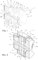
- a first variant embodiment of a magnetic compensation device 5 illustrated in FIGS. Figures 1 to 3 comprises two magnets 51, in the form of parallelepiped blocks, fixed on the housing 12 of the apparatus 1 by any suitable fastening means, and arranged diametrically opposite to form the first magnetic part.
- a single magnet 51 or more than two magnets 51 preferably distributed at regular intervals could also be suitable.
- the magnetic compensation device 5 also comprises a ring gear 52 fixed to the drive shaft 11 by any fastening means suitable for constituting the second magnetic or ferromagnetic part.
- This ring 52 may be annular or formed of a solid disk as shown.
- the magnets 51 and the ring 52 are, in this variant, aligned radially and separated from each other by an air gap, called "compensation gap Ec" which extends radially and in which a magnetic field generates a magnetic attraction or force.
- the magnets 51 are preferably independent north-south permanent magnets, whose magnetic field closes on themselves, the north-south faces being perpendicular to said compensation gap Ec.
- the ring 52 is for example crenellated to present facing magnets 51 an alternating profile of the recesses 53 and teeth 54 to generate an alternation of small and large differences in the compensation gap Ec.
- the ring 52 may be independently made of a ferromagnetic material or a magnetic material.
- the recesses 53 and the teeth 54 are cut into the mass of a wheel, as shown diagrammatically in FIGS. Figures 10 and 11 .
- the magnets 51 can be oriented independently to present in the compensation gap Ec as well as a south face than a North face.
- the teeth 54 may be formed by magnets 54a preferably carried by a crown support 55 of non-magnetic material, as shown schematically in FIG. figure 12 .
- the magnets 54a forming the teeth 54 are preferably independent north-south permanent magnets, like the magnets 51, and are oriented so that the faces of the magnets 51, 54a opposite in the compensation gap Ec are of inverse polarities.
- the teeth 54 and the equivalent of the recesses 53 may be formed by magnets 54a, 53a carried by a crown support 55 of non-magnetic material, such as independent permanent north-south magnets.
- the polarity of the magnets 53a replacing the recesses 53 is reversed relative to the polarity of the magnets 54a forming the teeth 54 so that the faces of the magnets 51, 54a and 51, 53a opposite in the compensation gap Ec are inverse polarity at the teeth 54 and the same polarity at the recesses 53.
- the recesses 53 or the equivalent of the recesses, and the teeth 54 may have a substantially trapezoidal section, although a square or rectangular section may also be suitable.
- the teeth 54 and the recesses 53 have opposite said magnets 51 a substantially identical surface, such as a square or rectangular surface.
- the teeth 54 of the ring 52 are preferably separated by an angular pitch Pc substantially equal to the angular pitch P 4 of the magnetocaloric elements 4 on their support 30.
- the two magnets 51 may be axially aligned on two diametrically opposed ZP passive zones of said support 3, as illustrated by transparency to the figure 3 , or on two active zones ZA or else on any other part of the support 3, the essential being that they generate with the ring 52 a magnetic compensation torque Cc which is in phase opposition with the driving torque Ce.
- FIG. figure 9 particularly illustrates an unstable equilibrium position of the magnetic arrangement 2 with respect to the support 3 in which each permanent magnet 21 of said magnetic arrangement 2 is in a balanced position, straddling an angular sector extending between two passive half-zones ZP.
- the magnetic compensation device 5 In this unstable equilibrium position, the magnetic compensation device 5 must either have no no influence on the drive device 10, or generate a force facilitating the output of the stable position.
- the magnetic compensation device 5 must generate a magnetic compensation torque Cc coming to oppose the natural effort of the magnetic arrangement 2 tending to return at its stable position. This is the reason why, in the unstable equilibrium position illustrated in figure 3 , the magnetic compensation device 5 is also in a position of equilibrium in that the magnets 51 are disposed facing recesses 53 of the ring 52 so as not to generate a magnetic compensation torque Cc.
- the figure 4 illustrates a second variant embodiment of a magnetic compensation device 6 which differs from the first embodiment according to the Figures 1 to 3 by the relative disposition of the ring gear 62 with respect to the magnets 61.
- the two magnets 61 are fixed on the housing 12 of the apparatus 1, arranged diametrically opposite and for example aligned axially on two passive zones ZP of the support 3.
- the ring gear 62 is fixed on the motor shaft 11 but offset axially with respect to the magnets 61 to delimit between them two compensation gaps Ec which are axially distributed.
- the ring 62 presents, facing magnets 61, an alternating profile of recesses 63 and teeth 64 which create an alternation of absences and presences of compensation gaps Ec having the same technical effect as before, namely to create an alternation of different magnetic permeabilities which is in opposition to the phase generated by the support 3 of magnetocaloric elements 4.
- the figure 5 illustrates a third embodiment of a magnetic compensation device 7 whose relative disposition of the ring 72 relative to the magnets 71 is similar to the first embodiment illustrated in FIGS. Figures 1 to 3 that they are aligned radially and separated by two compensating gaps Ec which extend radially.
- the difference lies in the design of the ring 72 which consists of a crown support 75 made in a non-magnetic material and a plurality of teeth 74 made of a ferromagnetic or magnetic material, attached to the periphery of the crown support 75, and oriented axially to create a compensation gap Ec with each of the magnets 71.
- the teeth 74 are distributed at regular intervals to respect an angular pitch Pc substantially equal to the angular pitch P 4 which separate the adjacent magnetocaloric elements 4, and define between them recesses 73.
- the alternation of the teeth 74 and recesses 73 creates an alternation of presences and absences of compensating gaps Ec having the same technical effect as before, namely to create an alternation of different magnetic permeabilities which is in opposition to the phase generated by the support 3 of magnetocaloric elements 4.
- the figure 6 illustrates a fourth variant embodiment of a magnetic compensation device 8 which differs from the third variant embodiment of the figure 5 by the relative disposition of the ring 82 relative to the magnets 81, namely that they are offset axially and separated by two compensation gaps Ec which extend axially.
- the ring 82 consists of a crown support 85 made of a non-magnetic material and a plurality of teeth 84 made of a ferromagnetic or magnetic material, attached to the periphery of said crown support 85, and oriented axially to create said Compensation gaps Ec with the magnets 81.
- the teeth 84 define hollows 73 between them and create an alternation of small and large gaps in the compensation gaps Ec having the same technical effect as in the previous examples, namely to create an alternation of different magnetic permeabilities which is in opposition to the phase generated by the support 3 of magnetocaloric elements 4.
- a magnetic compensation device 5-8 disposed outside the heat-generating gap E 1 , E 2 of said apparatus 1 illustrate some possible combinations between the first and second magnetic or magnetic / ferromagnetic parts. component said device magnetic compensation added to said apparatus.
- the fixed and moving parts which consist of the fixed magnets on the one hand and the ring driven in rotation by the drive device 10 on the other hand, can be reversed by providing the fixed ring and the magnets coupled to the device. 10 by any suitable coupling means.
- the number of magnets is not necessarily equal to two and may be equal to one or more than two, distributed at regular intervals to balance the magnetic forces at the level of the training device 10.
- the materials used on the one hand for the first magnetic part, namely the permanent magnets, and secondly for the second magnetic or ferromagnetic part, namely the ring, can be different or combined, the main thing being to generate a compensation magnetic force Cc in the Ec compensation gap that separates them, as explained above.
- the magnetic compensation device 5-8 as just described may further comprise means for adjusting the gap of the compensation gap Ec in order to adjust the magnetic compensation force oscillating with the oscillating driving force of the driving device 10.
- the magnets 51, 71 of the magnetic compensation devices 5 and 7, in which the compensation gaps Ec extend radially can be mounted on trolleys ( not shown) radially movable and coupled to an actuator driven by a control unit (not shown) as a function of the data of a force sensor (not shown) associated with the drive device 10 to adjust the deviation of the equilibrium gap Ec delimited between the magnets 51, 71 and the teeth 54, 74 of the ring 52, 72.
- This embodiment is not limiting and extends to any other deviation adjustment means ddi t ec compensating equilibrium gap.
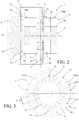
- the Figures 7 and 8 illustrate a fifth variant embodiment of a magnetic compensation device 9, in which it is totally integrated in the air gap of thermal generation E 1 , E 2 of said apparatus 1, thereby saving space.
- the first magnetic part of the compensation device 9 is in this case confounded with the permanent magnets 21 belonging to the magnetic arrangement 2, which are rotated by the drive device 10.
- the second ferromagnetic part of the compensation device 9 is in this case constituted by a plurality of ferromagnetic elements 90 added to the support 3, in the passive zones ZP devoid of magnetocaloric elements 4.
- These ferromagnetic elements 90 have a triangular section which fits in the free space between two 4 consecutive magnetocaloric elements.
- these ferromagnetic elements 90 in the passive zones ZP of the support 3 creates with the permanent magnets 21 of the magnetic arrangement 2 a magnetic compensation torque Cc oscillating which is in phase opposition with the driving torque Ce oscillating
- these added ferromagnetic elements 90 tend to create, with the magnetocaloric elements 4, a continuity of the magnetic permeability in said support 3, reducing or even eliminating jerks in the drive device.
- the magnetic compensation device 5-9 can be realized by any known manufacturing process.
- the magnetic, ferromagnetic and non-magnetic parts of the various magnetic compensation devices described can be made for example for the magnetic (hard) material: a ferrite, an NdFeB alloy composed of neodymium, iron and boron, an AlClO alloy composed mainly of aluminum nickel and cobalt, a SmCo alloy composed of samarium and cobalt, or the like; for the ferromagnetic material: iron, steel (except stainless steel, for example: ferritic or martensitic), nickel or the like; and for the non-magnetic material: typically aluminum, stainless steel, plastics (plastics), an epoxy resin with or without glass fibers.
- the magnetic (hard) material a ferrite, an NdFeB alloy composed of neodymium, iron and boron, an AlClO alloy composed mainly of aluminum nickel and cobalt, a SmCo alloy composed of samarium and co
- the magnetocaloric elements 4 and the ferromagnetic elements 90 of the apparatus illustrated in FIGS. Figures 7 and 8 can be integrated in the support 3 by any known assembly method according to whether the ferromagnetic elements require a simple mechanical connection or a sealed housing.
- the support 3 receiving these elements 4 and 90 may thus consist of a box with a sealed lid or not, screwed, welded, glued or the like.
- the ferromagnetic elements 90 may for example be glued, overmoulded, co-molded, clipped, or inserted into the housing in force.
- the support 3 is preferably made of insulating and non-magnetic material, such as a material synthetic material such as, for example, a polyamide in the case of an injected part, or a PEEK polyetheretherketone in the case of a machined part, an epoxy resin filled with glass fibers, or the like.
- a material synthetic material such as, for example, a polyamide in the case of an injected part, or a PEEK polyetheretherketone in the case of a machined part, an epoxy resin filled with glass fibers, or the like.
- the invention achieves, by a specifically dedicated magnetic compensation device 5-9 and designed for this function, this device being mechanically simple, economical, compact, easy to implement and easily adaptable, the goals set, namely an automatic and total magnetic compensation of the torque or the driving force in a magnetocaloric heat device 1, promoting a relative displacement of the magnetic arrangement 2 with respect to the magnetocaloric elements 4 as constant as possible , thus making it possible to limit the fatigue of the moving parts and to optimize the thermal efficiency of said apparatus 1.
Abstract
La présente invention concerne un appareil thermique magnétocalorique (1) ayant une structure rotative, pourvu d'un arrangement magnétique (2) définissant un entrefer de génération thermique (E 1 , E 2 ), dans lequel circule un champ magnétique, d'un support (3) placé dans ledit entrefer et portant des éléments magnétocaloriques (4) répartis dans des zones actives (ZA) séparées par des zones passives (ZA), et d'un dispositif d'entraînement (10) couplé en rotation avec ledit arrangement magnétique (2). Il comporte en outre un dispositif de compensation magnétique (5) ajouté, comportant deux aimants (51) diamétralement opposés, fixés sur le carter (12) dudit appareil, et une couronne (52) crénelée, en matériau magnétique ou ferromagnétique, couplée en rotation avec ledit dispositif d'entrainement (10), et définissant avec chacun desdits aimants (51) un entrefer de compensation (Ec) dans lequel circule une alternance de dents (54) et de creux (53) générant un couple de compensation magnétique (Cc) oscillant en opposition de phase avec le couple d'entraînement (Ce) oscillant dudit dispositif d'entrainement (10).The present invention relates to a magnetocaloric thermal apparatus (1) having a rotating structure, provided with a magnetic arrangement (2) defining a thermal generation gap (E 1, E 2), in which a magnetic field circulates, a support (3) placed in said gap and carrying magnetocaloric elements (4) distributed in active zones (ZA) separated by passive zones (ZA), and a driving device (10) coupled in rotation with said magnetic arrangement (2). It further comprises a magnetic compensation device (5) added, comprising two magnets (51) diametrically opposed, fixed on the housing (12) of said apparatus, and a ring (52) crenellated, of magnetic or ferromagnetic material, rotatably coupled with said drive device (10), and defining with each of said magnets (51) a compensation gap (Ec) in which an alternating sequence of teeth (54) and recesses (53) generating a magnetic compensation torque (Cc) ) oscillating in phase opposition with the oscillating driving torque (Ce) of said driving device (10).
Description
La présente invention concerne un appareil thermique magnétocalorique comportant un arrangement magnétique définissant au moins un entrefer, appelé « entrefer de génération thermique », dans lequel circule un champ magnétique, au moins un support placé dans le plan médian dudit au moins un entrefer de génération thermique et portant des éléments magnétocaloriques répartis dans des zones actives séparées par des zones passives dépourvues d'éléments magnétocaloriques, les zones actives ayant une perméabilité magnétique supérieure aux zones passives, un dispositif d'entraînement agencé pour déplacer ledit arrangement magnétique ou ledit au moins un support relativement l'un par rapport à l'autre afin de faire entrer et sortir lesdits éléments magnétocaloriques dudit au moins un entrefer de génération thermique pour qu'ils subissent des cycles magnétiques successifs, lesdits cycles magnétiques générant au sein dudit dispositif d'entraînement une force d'entrainement oscillante due à une alternance de perméabilités magnétiques différentes entre les zones actives et les zones passives dudit support, appareil comportant en outre un dispositif de compensation magnétique agencé pour créer une force de compensation magnétique oscillante déphasée par rapport à la force d'entraînement oscillante dudit dispositif d'entraînement pour générer une force résultante oscillante dont l'amplitude est inférieure à l'amplitude de la force d'entrainement oscillante.The present invention relates to a magnetocaloric thermal apparatus comprising a magnetic arrangement defining at least one air gap, called "thermal generation gap", in which a magnetic field circulates, at least one support placed in the median plane of said at least one thermal generation gap. and carrying magnetocaloric elements distributed in active zones separated by passive zones devoid of magnetocaloric elements, the active zones having a magnetic permeability greater than the passive zones, a driving device arranged to move said magnetic arrangement or said at least one support relatively to each other in order to enter and exit said magnetocaloric elements of said at least one heat generation gap so that they undergo successive magnetic cycles, said magnetic cycles generating within said drive device a oscillating drive unit due to an alternation of different magnetic permeabilities between the active zones and the passive zones of said support, the apparatus further comprising a magnetic compensation device arranged to create an oscillating magnetic compensation force out of phase with the force of oscillating drive of said driving device for generating an oscillating resultant force whose amplitude is smaller than the amplitude of the oscillating driving force.
La présente invention concerne le domaine du froid magnétique, et plus particulièrement celui des appareils thermiques utilisant l'effet magnétocalorique de matériaux dits magnétocaloriques.The present invention relates to the field of magnetic refrigeration, and more particularly that of thermal devices using the magnetocaloric effect of so-called magnetocaloric materials.
L'effet magnétocalorique (EMC) des matériaux magnétocaloriques consiste en une variation de leur température lorsqu'ils sont soumis à un champ magnétique variable en intensité. Il suffit ainsi de soumettre ces matériaux à une succession de cycles magnétiques comportant une alternance de phases de magnétisation et de démagnétisation et de réaliser un échange thermique avec un fluide caloporteur traversant lesdits matériaux de part en part pour parvenir à une variation de température la plus élargie possible entre les extrémités desdits matériaux. L'aimantation et la désaimantation des matériaux magnétocaloriques se fait par un déplacement relatif d'un arrangement magnétique par rapport auxdits matériaux magnétocaloriques suivant un mouvement qui peut être quelconque mais qui est généralement linéaire ou rotatif. Ce cycle magnétique est répété jusqu'à des fréquences de plusieurs Hertz. L'efficacité d'un tel cycle de réfrigération magnétique surpasse d'environ 50 % celle d'un cycle de réfrigération classique.The magnetocaloric effect (EMC) of magnetocaloric materials consists of a variation of their temperature when they are subjected to a variable magnetic field in intensity. It suffices to subject these materials to a succession of magnetic cycles comprising an alternation of magnetization and demagnetization phases and to carry out a heat exchange with a heat transfer fluid passing through said materials from one end to the other to obtain a widest temperature variation. possible between the ends of said materials. The magnetization and demagnetization of the magnetocaloric materials is by a relative displacement of a magnetic arrangement with respect to said magnetocaloric materials in a movement that may be arbitrary but is generally linear or rotational. This magnetic cycle is repeated up to frequencies of several Hertz. The efficiency of such a magnetic refrigeration cycle is about 50% greater than that of a typical refrigeration cycle.
Le matériau magnétocalorique s'échauffe de manière quasi-instantanée quand il est placé dans un champ magnétique et se refroidit suivant une même dynamique thermique quand il est retiré du champ magnétique. Pendant ces phases magnétiques, le fluide caloporteur va, soit se réchauffer au contact du matériau magnétocalorique lors d'une phase dite de magnétisation, soit se refroidir au contact du matériau magnétocalorique lors d'une phase dite de démagnétisation. De manière générale, dans les applications fonctionnant à température ambiante, le fluide caloporteur est un liquide et circule dans des canaux rectilignes ou des pores débouchants existants dans le matériau magnétocalorique. A cet effet, le liquide caloporteur peut être de l'eau pure ou additionnée d'antigel, un produit glycolé ou une saumure, par exemple.The magnetocaloric material heats up almost instantaneously when it is placed in a magnetic field and cools with the same thermal dynamics when it is removed from the magnetic field. During these magnetic phases, the heat transfer fluid will either be heated in contact with the magnetocaloric material during a so-called magnetization phase, or be cooled in contact with the magnetocaloric material during a so-called demagnetization phase. Generally, in applications operating at ambient temperature, the coolant is a liquid and circulates in straight channels or through pores existing in the magnetocaloric material. For this purpose, the coolant can be pure water or added antifreeze, a glycol product or a brine, for example.
Plus le champ magnétique est élevé dans l'entrefer, plus l'effet magnétocalorique induit dans le matériau magnétocalorique est important, ce qui a pour effet d'augmenter la puissance thermique aussi bien que son gradient de température entre ses deux extrémités d'entrée/sortie du fluide caloporteur, et donc le rendement global d'un tel appareil thermique magnétocalorique. De la même manière, quand la fréquence des cycles augmente, la puissance thermique (par exemple : le refroidissement) délivrée par l'appareil thermique augmente également. Pour que cette puissance augmente en proportion de l'augmentation de la fréquence, il est nécessaire d'avoir un arrangement magnétique susceptible de pouvoir générer un champ magnétique uniforme et intense dans au moins un entrefer et de pouvoir réaliser le déplacement relatif de cet arrangement magnétique par rapport aux éléments magnétocaloriques en consommant le moins d'énergie possible.The higher the magnetic field in the air gap, the greater the magnetocaloric effect induced in the magnetocaloric material, which has the effect of increasing the thermal power as well as its temperature gradient between its two input ends. heat transfer fluid outlet, and therefore the overall efficiency of such a magnetocaloric thermal device. In the same way, when the As the frequency of the cycles increases, the thermal power (for example: cooling) delivered by the thermal apparatus also increases. For this power to increase in proportion to the increase of the frequency, it is necessary to have a magnetic arrangement capable of generating a uniform and intense magnetic field in at least one gap and to be able to achieve the relative displacement of this magnetic arrangement. compared to the magnetocaloric elements by consuming the least energy possible.
A cet effet, les appareils thermiques magnétocaloriques à structure rotative sont privilégiés car la configuration rotative permet de réaliser un appareil thermique compact, d'autoriser un déplacement relatif continu de l'arrangement magnétique par rapport aux éléments magnétocaloriques ou inversement, et de présenter un bon ratio d'éléments magnétocaloriques par volume utilisé. Etant donné que la puissance thermique de l'appareil thermique dépend notamment de la quantité de matériaux magnétocaloriques utilisée, une telle disposition est effectivement très avantageuse. La demanderesse a déposé à cet effet les demandes de brevets
Le déplacement du fluide caloporteur devant être synchronisé avec le cycle magnétique, les matériaux magnétocaloriques sont regroupés sous la forme de zones actives, discrètes, appelées communément des « lits » ou des « éléments » magnétocaloriques, dans chacune desquelles les matériaux magnétocaloriques sont dans un état magnétique sensiblement équivalent permettant le déplacement du fluide caloporteur à leur contact de manière synchrone avec leur état magnétique. Pour des raisons pratiques et/ou géométriques, les matériaux magnétocaloriques sont donc mis en forme ou configurés en zones actives, discrètes, non contigües, séparées par des zones passives, ne contenant pas de matériaux magnétocaloriques, typiquement des parois de logement, des éléments de structure, de l'air ou similaire.Since the displacement of the coolant must be synchronized with the magnetic cycle, the magnetocaloric materials are grouped together in the form of discrete active zones, commonly called "beds" or magnetocaloric "elements", in each of which the magnetocaloric materials are in a state. substantially equivalent magnetic circuit for moving the coolant to contact them synchronously with their magnetic state. For practical and / or geometrical reasons, the magnetocaloric materials are therefore shaped or configured as active zones, discrete, non-contiguous, separated by passive zones, not containing magnetocaloric materials, typically housing walls, structural elements, air or the like.
Par ailleurs, étant donné que la perméabilité magnétique de l'air ou celle des zones passives ne comportant pas de matériaux magnétocaloriques est inférieure à celle des zones actives comportant des matériaux magnétocaloriques, le déplacement relatif des éléments magnétocaloriques par rapport à l'arrangement magnétique ou inversement entraîne dans l'entrefer une alternance de différentes perméabilités magnétiques, avec une attraction ou une force magnétique plus importante au passage des éléments magnétocaloriques et inversement une attraction ou une force magnétique plus faible au passage des zones séparant deux éléments magnétocaloriques consécutifs. Cette variation d'attractions ou d'efforts magnétiques perturbe le déplacement ou la vitesse angulaire de l'arrangement magnétique ou des éléments magnétocaloriques. De fait, ce déplacement ou cette vitesse angulaire n'est pas naturellement continu, ni uniforme et subit des à-coups. Cette situation est néfaste car elle perturbe le cycle magnétique en réduisant la puissance thermique et en augmentant la consommation d'énergie. Elle entraîne également une augmentation du niveau sonore de fonctionnement de l'appareil due aux vibrations engendrées et a une incidence négative sur son endurance et sur sa stabilité mécanique. Elle impose en outre un surdimensionnement du système de motorisation de l'arrangement magnétique ou des éléments magnétocaloriques pour accepter les pics d'efforts ou les variations de couples.On the other hand, since the magnetic permeability of the air or that of the passive zones not comprising magnetocaloric materials is less than that of the active zones comprising magnetocaloric materials, the relative displacement of the magnetocaloric elements with respect to the magnetic arrangement or conversely, the air gap causes alternation of different magnetic permeabilities, with a greater magnetic attraction or force when the magnetocaloric elements pass, and conversely a smaller magnetic attraction or force when passing through the zones separating two consecutive magnetocaloric elements. This variation of magnetic attractions or stresses disturbs the displacement or the angular velocity of the magnetic arrangement or the magnetocaloric elements. In fact, this displacement or this angular velocity is not naturally continuous, nor uniform and undergoes jolts. This situation is harmful because it disrupts the magnetic cycle by reducing the thermal power and increasing the energy consumption. It also causes an increase in the operating sound level of the device due to the vibrations generated and has a negative impact on its endurance and on its mechanical stability. It also imposes an oversizing of the motorization system of the magnetic arrangement or the magnetocaloric elements to accept peaks of effort or torque variations.
La construction des appareils thermiques magnétocaloriques actuels propose de limiter l'impact de ce phénomène en compensant la sortie du champ magnétique d'un des éléments magnétocaloriques par l'entrée dans le champ magnétique simultanée d'un autre élément magnétocalorique. Cette compensation du couple moteur ou de l'effort moteur n'est néanmoins pas parfaite pour de multiples raisons. La perméabilité magnétique des éléments magnétocaloriques dépend de la température instantanée desdits éléments et de leur température de Curie, et peut de ce fait ne pas être égale entre un élément magnétocalorique sortant du champ et un autre élément magnétocalorique entrant dans le champ. Le profil de transition du champ magnétique de l'entrefer aux éléments magnétocaloriques n'est pas parfait et comporte des dispersions ou distorsions, contribuant à un résultat aléatoire. La configuration de l'appareil thermique magnétocalorique impose des contraintes géométriques ou techniques quant à la disposition spatiale des éléments magnétocaloriques entre eux, qui peut empêcher la disposition préconisée ci-dessus. Cette solution n'est donc pas satisfaisante.The construction of current magnetocaloric thermal devices proposes to limit the impact of this phenomenon by compensating the output of the magnetic field of one of the magnetocaloric elements by the entry into the simultaneous magnetic field of another magnetocaloric element. This compensation of engine torque or engine effort is nevertheless not perfect for many reasons. The magnetic permeability of the magnetocaloric elements depends on the temperature instantaneous of said elements and their Curie temperature, and may therefore not be equal between a magnetocaloric element leaving the field and another magnetocaloric element entering the field. The transition profile of the magnetic field of the air gap to the magnetocaloric elements is not perfect and comprises dispersions or distortions, contributing to a random result. The configuration of the magnetocaloric thermal apparatus imposes geometric or technical constraints on the spatial arrangement of the magnetocaloric elements with each other, which can prevent the arrangement recommended above. This solution is therefore not satisfactory.
La publication
La présente invention vise à résoudre ces inconvénients en proposant un appareil thermique magnétocalorique agencé pour compenser plus efficacement, voire totalement les variations de perméabilité magnétique induites par l'agencement des éléments magnétocaloriques, permettant de limiter voire de supprimer les à-coups, dans le but d'obtenir un déplacement relatif de l'arrangement magnétique par rapport aux éléments magnétocaloriques le plus constant possible, permettant ainsi de préserver la puissance thermique de l'appareil, limiter la consommation d'énergie, réduire le niveau sonore de fonctionnement de l'appareil, préserver son endurance et sa stabilité mécanique, sans avoir besoin de surdimensionner le dispositif d'entraînement.The present invention aims to solve these drawbacks by proposing a magnetocaloric thermal apparatus arranged to compensate more effectively, indeed totally the variations of magnetic permeability induced by the arrangement of the magnetocaloric elements, making it possible to limit or even to suppress jolts, in order to obtain a relative displacement of the magnetic arrangement with respect to the magnetocaloric elements as constant as possible, thus preserving the thermal power of the device, limit energy consumption, reduce the operating sound level of the device, preserve its endurance and mechanical stability, without the need to oversize the drive device.
Dans ce but, l'invention concerne un appareil thermique magnétocalorique du genre indiqué en préambule, caractérisé en ce que ledit dispositif de compensation magnétique est un dispositif spécifique, au moins en partie ajouté audit appareil, et agencé pour créer une force de compensation magnétique oscillante qui est en opposition de phase à la force d'entraînement oscillante dudit dispositif d'entraînement pour tendre vers une force résultante constante, et en ce qu'il comporte une première pièce magnétique et une seconde pièce magnétique ou ferromagnétique, définissant entre elles un entrefer, appelé entrefer de compensation, dans lequel circule un champ magnétique, l'une des deux pièces étant couplée mécaniquement audit dispositif d'entraînement pour être déplacée de manière synchrone avec ledit arrangement magnétique ou ledit support relativement par rapport à l'autre pièce, l'une au moins des deux pièces comportant des zones de perméabilités magnétiques élevées alternées avec des zones perméabilités magnétiques faibles pour créer dans ledit entrefer de compensation ladite force de compensation magnétique oscillante.For this purpose, the invention relates to a magnetocaloric thermal apparatus of the type indicated in the preamble, characterized in that said magnetic compensation device is a specific device, at least partly added to said apparatus, and arranged to create an oscillating magnetic compensation force which is in phase opposition to the oscillating driving force of said driving device for tending towards a constant resultant force, and in that it comprises a first magnetic part and a second magnetic or ferromagnetic part, defining between them a gap called a compensating air gap in which a magnetic field circulates, one of the two parts being mechanically coupled to said drive device to be moved synchronously with said magnetic arrangement or said carrier relatively to the other part, at least one of the two parts having zones of permeabilities alternating high magnetic fields with weak magnetic permeability zones to create in said compensating air gap said oscillating magnetic compensation force.
Grâce à cette construction particulière, le dispositif de compensation magnétique peut être conçu et défini spécifiquement pour remplir sa fonction de compensation magnétique afin qu'elle soit la plus adaptée possible et donc la plus performante. Il est ainsi possible de créer une force de compensation magnétique oscillante qui est réellement en opposition de phase par rapport à la force d'entraînement oscillante du dispositif d'entraînement, et ceci sans introduire une quelconque désynchronisation magnéto-fluidique dans ledit appareil. Un autre avantage réside dans le fait que l'appareil thermique magnétocalorique peut ne comporter qu'un seul étage thermique, à l'inverse de la solution décrite dans la publication
Dans une forme de réalisation préférée de l'invention, l'appareil thermique magnétocalorique a une structure rotative autour d'un axe longitudinal, ledit au moins un support présente une forme circulaire centrée sur ledit axe longitudinal, lesdits éléments magnétocaloriques sont répartis sur ledit au moins un support dans lesdites zones actives séparées entre-elles d'un pas angulaire constant, et ledit dispositif d'entraînement est agencé pour déplacer ledit arrangement magnétique ou ledit au moins un support en rotation relative de l'un par rapport à l'autre autour dudit axe longitudinal. Dans ce cas, le dispositif de compensation magnétique peut être disposé à l'extérieur de l'entrefer de génération thermique, et ladite première pièce magnétique comporte au moins un aimant disposé radialement à distance dudit axe longitudinal, et ladite seconde pièce magnétique ou ferromagnétique comporte une couronne, centrée sur l'axe longitudinal, présentant en regard dudit au moins un aimant une alternance de zones de perméabilités magnétiques élevées et faibles dans ledit entrefer de compensation.In a preferred embodiment of the invention, the magnetocaloric thermal apparatus has a structure rotatable about a longitudinal axis, said at least one support has a circular shape centered on said longitudinal axis, said magnetocaloric elements are distributed over said longitudinal axis. at least one support in said active areas separated from each other by a constant angular pitch, and said drive device is arranged to move said magnetic arrangement or said at least one support in relative rotation relative to each other around said longitudinal axis. In this case, the magnetic compensation device can be disposed outside the thermal generation gap, and said first magnetic member comprises at least one magnet disposed radially at a distance from said longitudinal axis, and said second magnetic or ferromagnetic piece comprises a ring, centered on the longitudinal axis, having opposite said at least one magnet alternating areas of high and low magnetic permeabilities in said compensation gap.
Ledit au moins un aimant peut être monté sur une partie fixe dudit appareil et ladite couronne peut être couplée en rotation avec ledit dispositif d'entraînement. Inversement, ledit au moins un aimant peut être couplé en rotation avec ledit dispositif d'entraînement et ladite couronne peut être montée sur une partie fixe dudit appareil.The at least one magnet may be mounted on a fixed portion of said apparatus and said ring may be rotatably coupled with said driver. Conversely, said at least one magnet can be rotatably coupled with said driver and said crown can be mounted on a fixed portion of said apparatus.
Selon la variante de réalisation de l'invention, ledit au moins un aimant et ladite couronne sont alignés radialement, et ledit entrefer de compensation s'étend radialement, ou ledit au moins un aimant et ladite couronne sont alignés axialement, et ledit entrefer de compensation s'étend axialement.According to the variant embodiment of the invention, said at least one magnet and said ring are aligned radially, and said compensation gap extends. radially, or said at least one magnet and said ring are axially aligned, and said compensation gap extends axially.
La couronne peut être crénelée et comporter une alternance de dents et de creux, lesdites dents étant séparées d'un pas angulaire sensiblement égal au pas angulaire séparant les zones actives dudit support.The ring may be crenellated and have an alternation of teeth and recesses, said teeth being separated by an angular pitch substantially equal to the angular pitch separating the active areas of said support.
Cette couronne peut être réalisée en matériau ferromagnétique, ou comporter un support de couronne en matériau amagnétique et des éléments ferromagnétiques disposés en couronne sur ledit support de couronne, formant des dents séparées d'un pas angulaire sensiblement égal au pas angulaire séparant les zones actives dudit support.This ring may be made of ferromagnetic material, or comprise a crown support of non-magnetic material and ferromagnetic elements arranged in a ring on said crown support, forming teeth separated by an angular pitch substantially equal to the angular pitch separating the active zones of said support.
Cette couronne peut également comporter des aimants formant les dents alternées avec des creux, lesdits aimants étant montés sur un support de couronne en matériau amagnétique, et orientés pour que les faces des aimants en regard dans ledit entrefer de compensation soient de polarités opposées. Elle peut encore comporter une succession d'aimants de polarités inversées et disposés de manière alternée pour que les faces des aimants en regard dans ledit entrefer de compensation soient alternativement de polarités opposées et de même polarité.This ring may also comprise magnets forming the alternating teeth with recesses, said magnets being mounted on a crown support of non-magnetic material, and oriented so that the faces of the magnets opposite in said compensation gap are of opposite polarities. It may also comprise a succession of magnets of inverted polarities and arranged alternately so that the faces of the magnets facing in said compensation gap are alternately opposite polarities and the same polarity.
En option, le dispositif de compensation magnétique peut comporter en outre des moyens de réglage de l'écart dudit entrefer de compensation pour ajuster la force de compensation magnétique oscillante à la force d'entraînement oscillante dudit dispositif d'entraînement. Dans ce cas, ledit au moins un aimant peut être monté sur un chariot, et lesdits moyens de réglage peuvent comporter un actionneur couplé audit chariot et piloté par un capteur d'effort associé audit dispositif d'entraînement.Optionally, the magnetic compensation device may further include means for adjusting the deviation of said compensation gap to adjust the oscillating magnetic compensation force to the oscillating driving force of said driving device. In this case, said at least one magnet can be mounted on a carriage, and said adjustment means can comprise an actuator coupled to said carriage and controlled by a force sensor associated with said drive device.
Dans la forme préférée de l'appareil thermique magnétocalorique selon l'invention, ayant une structure rotative autour d'un axe longitudinal, ledit dispositif de compensation magnétique peut également être disposé à l'intérieur de l'entrefer de génération thermique, ladite première pièce magnétique étant confondue avec lesdits au moins deux aimants permanents dudit arrangement magnétique, et ladite seconde pièce comportant des éléments ferromagnétiques ajoutés sur ledit support, dans les zones passives dépourvues d'éléments magnétocaloriques, pour créer ladite force de compensation magnétique oscillante.In the preferred form of the magnetocaloric thermal apparatus according to the invention, having a structure rotatable about a longitudinal axis, said device for magnetic compensation may also be arranged inside the thermal generation gap, said first magnetic part being merged with said at least two permanent magnets of said magnetic arrangement, and said second part having ferromagnetic elements added on said support, in the passive zones devoid of magnetocaloric elements, for creating said oscillating magnetic compensation force.
Dans ce cas, ledit arrangement magnétique peut être monté sur une partie fixe dudit appareil et ledit support peut être couplé en rotation avec ledit dispositif d'entraînement, ou inversement, ledit arrangement magnétique peut être couplé en rotation avec ledit dispositif d'entraînement et ledit support peut être monté sur une partie fixe dudit appareil.In this case, said magnetic arrangement may be mounted on a fixed part of said apparatus and said support may be rotatably coupled to said driving device, or conversely, said magnetic arrangement may be rotatably coupled with said driving device and said bracket can be mounted on a fixed part of said apparatus.
La présente invention et ses avantages apparaîtront mieux dans la description suivante de plusieurs modes de réalisation donnés à titre d'exemples non limitatifs, en référence aux dessins annexés, dans lesquels:
- la
figure 1 est une vue en coupe axiale et en perspective d'une partie d'un appareil thermique magnétocalorique selon une première forme de réalisation de l'invention, - la
figure 2 est une vue en coupe axiale en plan de l'appareil de lafigure 1 , - la
figure 3 est une vue en bout en transparence de lafigure 1 , - la
figure 4 est une vue similaire à lafigure 1 d'un appareil thermique magnétocalorique selon une deuxième forme de réalisation de l'invention, - la
figure 5 est une vue similaire à lafigure 1 d'un appareil thermique magnétocalorique selon une troisième forme de réalisation de l'invention, - la
figure 6 est une vue similaire à lafigure 1 d'un appareil thermique magnétocalorique selon une quatrième forme de réalisation de l'invention, - la
figure 7 est une vue similaire à lafigure 1 d'un appareil thermique magnétocalorique selon une cinquième forme de réalisation de l'invention, - la
figure 8 est une vue en bout de lafigure 7 , - la
figure 9 est un diagramme illustrant l'intérêt du couple de compensation magnétique, et - les
figures 10 à 13 sont des représentations schématiques linéaires de différentes formes de réalisation du dispositif de compensation magnétique selon l'invention.
- the
figure 1 is a view in axial section and in perspective of a part of a magnetocaloric thermal apparatus according to a first embodiment of the invention, - the
figure 2 is an axial axial sectional view of the apparatus of thefigure 1 , - the
figure 3 is an end view in transparency of thefigure 1 , - the
figure 4 is a view similar to thefigure 1 a magnetocaloric thermal apparatus according to a second embodiment of the invention, - the
figure 5 is a view similar to thefigure 1 a magnetocaloric thermal apparatus according to a third embodiment of the invention, - the
figure 6 is a view similar to thefigure 1 a magnetocaloric thermal apparatus according to a fourth embodiment of the invention, - the
figure 7 is a view similar to thefigure 1 a magnetocaloric thermal apparatus according to a fifth embodiment of the invention, - the
figure 8 is an end view of thefigure 7 , - the
figure 9 is a diagram illustrating the interest of the magnetic compensation torque, and - the
Figures 10 to 13 are linear schematic representations of different embodiments of the magnetic compensation device according to the invention.
En référence aux figures, la présente invention concerne un appareil thermique magnétocalorique 1, appelé par la suite «appareil 1 », de structure rotative autour d'un axe longitudinal A qui comporte de manière connue :
- un arrangement magnétique 2 définissant au moins un entrefer et, dans les exemples représentés, deux entrefers diamétralement opposés, appelés « entrefer de génération thermique E1, E2 », dans lesquels circule un champ magnétique,
- au moins
un support 3 placé sensiblement dans le plan médian P desdits entrefers de génération thermique E1, E2, ce support portant des éléments magnétocaloriques 4 répartis dans des zones actives ZA séparées par des zones passives ZP dépourvues d'éléments magnétocaloriques, un dispositif d'entraînement 10 agencé pour déplacer ledit arrangement magnétique 2 ou ledit au moinsun support 3 selon un mouvement rotatif relatif de l'un par rapport à l'autre de sorte que les éléments magnétocaloriques 4 puissent entrer et sortir alternativement des entrefers de génération thermique E1, E2 et subissent ainsi des cycles magnétiques successifs créés par la présence d'un champ magnétique lorsqu'ils sont à l'intérieur desdits entrefer de génération thermique E1, E2, et par l'absence d'un champ magnétique lorsqu'ils sont à l'extérieur desdits entrefers de génération thermique E1, E2, et- un dispositif de mise en circulation (non représenté) d'au moins un fluide caloporteur au travers desdits éléments magnétocaloriques 4, et d'échangeurs de chaleur (non représentés) pour réaliser un échange thermique avec un environnement ou une application extérieure. Par application extérieure, on entend toute application aussi bien industrielle que domestique pour laquelle il est nécessaire de refroidir, climatiser, tempérer, chauffer, etc. un fluide gazeux ou liquide.
- a
magnetic arrangement 2 defining at least one gap and, in the examples shown, two diametrically opposed air gaps, called "thermal generation gap E 1 , E 2 ", in which circulates a magnetic field, - at least one
support 3 placed substantially in the median plane P of said thermal generation gaps E 1 , E 2 , this support carryingmagnetocaloric elements 4 distributed in active zones ZA separated by passive zones ZP devoid of magnetocaloric elements, - a driving
device 10 arranged to move saidmagnetic arrangement 2 or said at least onesupport 3 in a relative rotational movement relative to each other so that themagnetocaloric elements 4 can enter and exit alternately air gaps; thermal generation E 1 , E 2 and thus undergo successive magnetic cycles created by the presence of a magnetic field when they are inside said heat generation gap E 1 , E 2 , and by the absence of a magnetic field when they are outside said thermal generation gaps E 1 , E 2 , and - a device for circulating (not shown) at least one fluid heat transfer through said
magnetocaloric elements 4, and heat exchangers (not shown) to achieve a heat exchange with an environment or an external application. By external application is meant any industrial or domestic application for which it is necessary to cool, air condition, temper, heat, etc. a gaseous or liquid fluid.
Bien entendu, cet exemple n'est pas limitatif et s'étend à un appareil thermique magnétocalorique ayant une structure linéaire dans laquelle l'arrangement magnétique ou ledit au moins un support est déplacé selon un mouvement linéaire relatif de l'un par rapport à l'autre, ce mouvement étant nécessairement alternatif. Néanmoins, le mode de réalisation illustré a l'avantage de permettre un entraînement rotatif continu et une optimisation de la densité d'éléments magnétocaloriques dans un volume réduit.Of course, this example is not limiting and extends to a magnetocaloric thermal apparatus having a linear structure in which the magnetic arrangement or said at least one support is displaced in a relative linear motion of one relative to the other. other, this movement being necessarily alternative. Nevertheless, the illustrated embodiment has the advantage of allowing continuous rotary drive and optimization of the density of magnetocaloric elements in a reduced volume.
Dans les exemples illustrés dans les
Dans les exemples illustrés dans les
Dans les appareils thermiques magnétocaloriques 1 connus, et comme exposé précédemment dans l'état de l'art, la disposition des éléments magnétocaloriques 4 sur le support 3 génère des variations de perméabilité magnétique entre les zones actives ZA comportant des éléments magnétocaloriques 4 présentant une bonne perméabilité magnétique et les zones passives ZP dépourvues d'éléments magnétocaloriques présentant une perméabilité magnétique inférieure à celle des zones actives ZA. Lors du déplacement relatif de l'arrangement magnétique 2 par rapport aux éléments magnétocaloriques 4, ce phénomène génère au sein des entrefers de génération thermique E1, E2 une attraction ou une force magnétique plus importante au passage des zones actives ZA et inversement une attraction ou une force magnétique plus faible au passage des zones passives ZP séparant deux zones actives ZA consécutives. Ces variations d'effort magnétique impactent le fonctionnement du dispositif d'entraînement qui va fonctionner par à-coups générant un couple d'entrainement Ce oscillant, comme représenté par le diagramme de la
L'appareil thermique magnétocalorique 1 selon l'invention se différencie de l'état de l'art en ce qu'il comporte un dispositif de compensation magnétique 5-9 spécifiquement dédié, ajouté audit appareil, et couplé mécaniquement au dispositif d'entraînement 10 pour créer un couple de compensation magnétique Cc oscillant pour qu'il soit avantageusement en opposition de phase au couple d'entraînement Ce oscillant du dispositif d'entraînement, comme représenté par le diagramme de la
Ce dispositif de compensation magnétique 5-9 peut être disposé à l'extérieur des entrefers de génération thermique E1, E2 comme dans les
Les
De par la forme circulaire de la couronne 52, les creux 53 ou l'équivalent des creux, et les dents 54 peuvent présenter une section sensiblement trapézoïdale, bien qu'une section carrée ou rectangulaire puisse également convenir. De préférence, les dents 54 et les creux 53 présentent en regard desdits aimants 51 une surface sensiblement identique, telle qu'une surface carrée ou rectangulaire. Cette alternance de petits et de grands écarts dans l'entrefer de compensation Ec génère ainsi une alternance de perméabilités magnétiques différentes dans ledit entrefer de compensation Ec, créant une attraction ou une force magnétique plus importante au passage des dents 54 correspondant à une perméabilité magnétique élevée, et inversement une attraction ou une force magnétique plus faible au passage des creux 53 séparant deux dents 54 consécutives correspondant à une perméabilité magnétique faible. Les dents 54 de la couronne 52 sont de préférence séparées d'un pas angulaire Pc sensiblement égal au pas angulaire P4 des éléments magnétocaloriques 4 sur leur support 30. Les deux aimants 51 peuvent être alignés axialement sur deux zones passives ZP diamétralement opposées dudit support 3, comme illustré par transparence à la
La
La
La
Ces différentes variantes de réalisation d'un dispositif de compensation magnétique 5-8 disposé à l'extérieur de l'entrefer de génération thermique E1, E2 dudit appareil 1 illustrent quelques combinaisons possibles entre les première et seconde pièces magnétiques ou magnétique/ferromagnétique composant ledit dispositif de compensation magnétique ajouté audit appareil. Ces exemples ne sont pas limitatifs et s'étendent à toute autre variante de réalisation technique équivalente. Les pièces fixe et mobile, qui sont constituées par les aimants fixes d'une part et par la couronne entraînée en rotation par le dispositif d'entrainement 10 d'autre part, peuvent être inversées en prévoyant la couronne fixe et les aimants couplés au dispositif d'entraînement 10 par tout moyen de couplage approprié. Le nombre d'aimants n'est pas obligatoirement égal à deux et peut être égal à un ou à plus de deux, répartis à intervalles réguliers pour équilibrer les forces magnétiques au niveau du dispositif d'entrainement 10. Les matériaux utilisés d'une part pour la première pièce magnétique, à savoir les aimants permanents, et d'autre part pour la seconde pièce magnétique ou ferromagnétique, à savoir la couronne, peuvent être différents ou combinés, l'essentiel étant de générer une force magnétique de compensation Cc dans l'entrefer de compensation Ec qui les sépare, comme expliqué ci-dessus.These various embodiments of a magnetic compensation device 5-8 disposed outside the heat-generating gap E 1 , E 2 of said
En complément, le dispositif de compensation magnétique 5-8 tel qu'il vient d'être décrit peut comporter en outre des moyens de réglage de l'écart de l'entrefer de compensation Ec dans le but d'ajuster la force de compensation magnétique oscillante à la force d'entraînement oscillante du dispositif d'entraînement 10. Concrètement, les aimants 51, 71 des dispositifs de compensation magnétique 5 et 7, dans lesquels les entrefers de compensation Ec s'étendent radialement, peuvent être montés sur des chariots (non représentés) mobiles radialement et couplés à un actionneur piloté par une unité de commande (non représentée) en fonction des données d'un capteur d'effort (non représenté) associé au dispositif d'entraînement 10 pour ajuster l'écart de l'entrefer de compensation Ec délimité entre les aimants 51, 71 et les dents 54, 74 de la couronne 52, 72. Cet exemple de réalisation n'est pas limitatif et s'étend à tout autre moyen de réglage de l'écart dudit entrefer de compensation Ec techniquement équivalent.In addition, the magnetic compensation device 5-8 as just described may further comprise means for adjusting the gap of the compensation gap Ec in order to adjust the magnetic compensation force oscillating with the oscillating driving force of the driving
Les
Le dispositif de compensation magnétique 5-9 selon l'invention peut être réalisé par tout procédé de fabrication connu. Les pièces magnétiques, ferromagnétiques et amagnétiques des différents dispositifs de compensation magnétique décrits peuvent être réalisées par exemple, pour le matériau magnétique (dur) : une ferrite, un alliage NdFeB composé de néodyme, fer et bore, un alliage AINiCo composé principalement d'aluminium, nickel et cobalt, un alliage SmCo composé de samarium et cobalt, ou similaire ; pour le matériau ferromagnétique : du fer, de l'acier (hors inox, par exemple : ferritique ou martensitique), du nickel ou similaire ; et pour le matériau amagnétique : typiquement de l'aluminium, de l'inox, des matières synthétiques (plastiques), une résine époxy avec ou sans fibres de verre.The magnetic compensation device 5-9 according to the invention can be realized by any known manufacturing process. The magnetic, ferromagnetic and non-magnetic parts of the various magnetic compensation devices described can be made for example for the magnetic (hard) material: a ferrite, an NdFeB alloy composed of neodymium, iron and boron, an AlClO alloy composed mainly of aluminum nickel and cobalt, a SmCo alloy composed of samarium and cobalt, or the like; for the ferromagnetic material: iron, steel (except stainless steel, for example: ferritic or martensitic), nickel or the like; and for the non-magnetic material: typically aluminum, stainless steel, plastics (plastics), an epoxy resin with or without glass fibers.
Les éléments magnétocaloriques 4 et les éléments ferromagnétiques 90 de l'appareil illustré dans les
Par ailleurs et pour limiter les pertes thermiques vers l'extérieur de l'appareil et entre l'extrémité chaude et l'extrémité froide des éléments magnétocaloriques 4, le support 3 est de préférence réalisé en matière isolante et amagnétique, telle qu'une matière synthétique comme par exemple un polyamide dans le cas d'une pièce injectée, ou un polyétheréthercétone PEEK dans le cas d'une pièce usinée, une résine époxy chargée en fibres de verre, ou similaire.Moreover and to limit heat losses towards the outside of the apparatus and between the hot end and the cold end of the
Il ressort clairement de cette description que l'invention permet d'atteindre, par un dispositif de compensation magnétique 5-9 spécifiquement dédié et conçu pour cette fonction, ce dispositif étant mécaniquement simple, économique, peu encombrant, facile à mettre en oeuvre et facilement adaptable, les buts fixés, à savoir une compensation magnétique automatique et totale du couple ou de la force d'entraînement dans un appareil thermique magnétocalorique 1, favorisant un déplacement relatif de l'arrangement magnétique 2 par rapport aux éléments magnétocaloriques 4 le plus constant possible, permettant ainsi de limiter la fatigue des organes en mouvement et d'optimiser le rendement thermique dudit appareil 1.It is clear from this description that the invention achieves, by a specifically dedicated magnetic compensation device 5-9 and designed for this function, this device being mechanically simple, economical, compact, easy to implement and easily adaptable, the goals set, namely an automatic and total magnetic compensation of the torque or the driving force in a
La présente invention n'est pas limitée aux exemples de réalisation décrits mais s'étend à toute modification et variante évidentes pour un homme du métier.The present invention is not limited to the embodiments described but extends to any modification and variation obvious to a person skilled in the art.
Claims (16)
Applications Claiming Priority (1)
| Application Number | Priority Date | Filing Date | Title |
|---|---|---|---|
| FR1656183A FR3053448B1 (en) | 2016-06-30 | 2016-06-30 | MAGNETOCALORIC THERMAL APPARATUS |
Publications (2)
| Publication Number | Publication Date |
|---|---|
| EP3287716A1 true EP3287716A1 (en) | 2018-02-28 |
| EP3287716B1 EP3287716B1 (en) | 2022-08-03 |
Family
ID=57233589
Family Applications (1)
| Application Number | Title | Priority Date | Filing Date |
|---|---|---|---|
| EP17177465.6A Active EP3287716B1 (en) | 2016-06-30 | 2017-06-22 | Magnetocaloric thermal apparatus |
Country Status (2)
| Country | Link |
|---|---|
| EP (1) | EP3287716B1 (en) |
| FR (1) | FR3053448B1 (en) |
Families Citing this family (1)
| Publication number | Priority date | Publication date | Assignee | Title |
|---|---|---|---|---|
| FR3105726B1 (en) | 2019-12-31 | 2023-03-31 | Gramafam France | Device for keeping food hot and/or cold in a dish or the like |
Citations (4)
| Publication number | Priority date | Publication date | Assignee | Title |
|---|---|---|---|---|
| US20080223853A1 (en) * | 2004-03-30 | 2008-09-18 | Christian Muller | Heat Generator Comprising a Magneto-Caloric Material and Thermie Generating Method |
| FR2987433A1 (en) | 2012-02-28 | 2013-08-30 | Cooltech Applications | MAGNETIC FIELD GENERATOR FOR MAGNETOCALORIC THERMAL APPARATUS |
| FR2994018A1 (en) | 2012-07-27 | 2014-01-31 | Cooltech Applications | MAGNETIC FIELD GENERATOR FOR MAGNETOCALORIC THERMAL APPARATUS AND MAGNETOCALORIC THERMAL APPARATUS EQUIPPED WITH SUCH A GENERATOR |
| FR3028927A1 (en) | 2014-11-26 | 2016-05-27 | Cooltech Applications | MAGNETOCALORIC THERMAL APPARATUS |
-
2016
- 2016-06-30 FR FR1656183A patent/FR3053448B1/en active Active
-
2017
- 2017-06-22 EP EP17177465.6A patent/EP3287716B1/en active Active
Patent Citations (4)
| Publication number | Priority date | Publication date | Assignee | Title |
|---|---|---|---|---|
| US20080223853A1 (en) * | 2004-03-30 | 2008-09-18 | Christian Muller | Heat Generator Comprising a Magneto-Caloric Material and Thermie Generating Method |
| FR2987433A1 (en) | 2012-02-28 | 2013-08-30 | Cooltech Applications | MAGNETIC FIELD GENERATOR FOR MAGNETOCALORIC THERMAL APPARATUS |
| FR2994018A1 (en) | 2012-07-27 | 2014-01-31 | Cooltech Applications | MAGNETIC FIELD GENERATOR FOR MAGNETOCALORIC THERMAL APPARATUS AND MAGNETOCALORIC THERMAL APPARATUS EQUIPPED WITH SUCH A GENERATOR |
| FR3028927A1 (en) | 2014-11-26 | 2016-05-27 | Cooltech Applications | MAGNETOCALORIC THERMAL APPARATUS |
Also Published As
| Publication number | Publication date |
|---|---|
| FR3053448B1 (en) | 2019-07-26 |
| EP3287716B1 (en) | 2022-08-03 |
| FR3053448A1 (en) | 2018-01-05 |
Similar Documents
| Publication | Publication Date | Title |
|---|---|---|
| EP2283283B1 (en) | Thermal flux generating device with magnetocaloric material | |
| EP2878000B1 (en) | Magnetic field generator for a magnetocaloric thermal device, and magnetocaloric thermal device equipped with such a generator | |
| WO2016083440A1 (en) | Magnetocaloric thermal apparatus | |
| EP2129976B1 (en) | Method and device for increasing a temperature gradient in a magnetocaloric thermal generator | |
| EP2771628B1 (en) | Magnetocaloric heat generator | |
| EP2438453A2 (en) | Magnetic field generator and magnetocaloric device comprising said magnetic field generator | |
| EP2820361B1 (en) | Magnetic field generator for magnetocaloric thermal appliance | |
| EP3287716B1 (en) | Magnetocaloric thermal apparatus | |
| WO2017149434A1 (en) | Method for generating a magnetic field and magnetic field generator | |
| CA2687070A1 (en) | Electromagnetic actuator with variable reluctance | |
| EP2603747B1 (en) | Thermal generator containing magnetocaloric material | |
| EP3087329B1 (en) | Magnetocaloric thermal generator and method of cooling same | |
| EP2606495B1 (en) | Magnetic-field generator for a magnetocaloric thermal device | |
| EP4251934A1 (en) | Magnetocaloric machine | |
| FR2863787A1 (en) | Electromagnetic retarder`s annular rotor for terrestrial vehicle`s transmission, has undercut formed between lateral edge of axial end of fin and lateral side of induced disc for forming heat barrier | |
| FR2933537A1 (en) | Thermal flux generating device, has magnetocaloric element placed in air gap, where air gap is formed by space delimited between magnetic arrangement and armatures and space delimited between arrangement and external cylindrical casing | |
| EP2368279B1 (en) | Method for quickly establishing a temperature gradient in a magnetocaloric element, and magnetocaloric thermal generator implementing said method | |
| FR2930679A1 (en) | Thermal flow generating device, has electric coils supplied with electric current for generating variation of magnetic field to displace mobile assembly carrying magnetic arrangement, and thermal unit placed between coils and arrangement | |
| FR2963668A1 (en) | Heat generator for e.g. heating application, has isolation unit isolating magnetic assemblies from one another to form thermally isolated cells, where cells are filled with pressurized gas or low thermal conductivity gas mixture | |
| WO2012006752A2 (en) | Magnetic field generator, and magnetocaloric device comprising said magnetic field generator | |
| FR2919771A1 (en) | MAGNETIC MOTOR WITH PERMANENT MAGNETS | |
| FR2870402A1 (en) | Electric current generator for use as autonomous charger, has disk fixed on shaft opposite to bearing related to plate and windings, and including pairs of permanent magnets regularly distributed around its centre |
Legal Events
| Date | Code | Title | Description |
|---|---|---|---|
| PUAI | Public reference made under article 153(3) epc to a published international application that has entered the european phase |
Free format text: ORIGINAL CODE: 0009012 |
|
| STAA | Information on the status of an ep patent application or granted ep patent |
Free format text: STATUS: THE APPLICATION HAS BEEN PUBLISHED |
|
| AK | Designated contracting states |
Kind code of ref document: A1 Designated state(s): AL AT BE BG CH CY CZ DE DK EE ES FI FR GB GR HR HU IE IS IT LI LT LU LV MC MK MT NL NO PL PT RO RS SE SI SK SM TR |
|
| AX | Request for extension of the european patent |
Extension state: BA ME |
|
| STAA | Information on the status of an ep patent application or granted ep patent |
Free format text: STATUS: REQUEST FOR EXAMINATION WAS MADE |
|
| 17P | Request for examination filed |
Effective date: 20181211 |
|
| RBV | Designated contracting states (corrected) |
Designated state(s): AL AT BE BG CH CY CZ DE DK EE ES FI FR GB GR HR HU IE IS IT LI LT LU LV MC MK MT NL NO PL PT RO RS SE SI SK SM TR |
|
| STAA | Information on the status of an ep patent application or granted ep patent |
Free format text: STATUS: REQUEST FOR EXAMINATION WAS MADE |
|
| 19U | Interruption of proceedings before grant |
Effective date: 20180917 |
|
| 19W | Proceedings resumed before grant after interruption of proceedings |
Effective date: 20210601 |
|
| RAP1 | Party data changed (applicant data changed or rights of an application transferred) |
Owner name: FRANCE BREVETS |
|
| GRAP | Despatch of communication of intention to grant a patent |
Free format text: ORIGINAL CODE: EPIDOSNIGR1 |
|
| STAA | Information on the status of an ep patent application or granted ep patent |
Free format text: STATUS: GRANT OF PATENT IS INTENDED |
|
| INTG | Intention to grant announced |
Effective date: 20211209 |
|
| RAP1 | Party data changed (applicant data changed or rights of an application transferred) |
Owner name: UBIBLUE |
|
| GRAJ | Information related to disapproval of communication of intention to grant by the applicant or resumption of examination proceedings by the epo deleted |
Free format text: ORIGINAL CODE: EPIDOSDIGR1 |
|
| STAA | Information on the status of an ep patent application or granted ep patent |
Free format text: STATUS: REQUEST FOR EXAMINATION WAS MADE |
|
| INTC | Intention to grant announced (deleted) | ||
| GRAS | Grant fee paid |
Free format text: ORIGINAL CODE: EPIDOSNIGR3 |
|
| STAA | Information on the status of an ep patent application or granted ep patent |
Free format text: STATUS: GRANT OF PATENT IS INTENDED |
|
| GRAP | Despatch of communication of intention to grant a patent |
Free format text: ORIGINAL CODE: EPIDOSNIGR1 |
|
| GRAA | (expected) grant |
Free format text: ORIGINAL CODE: 0009210 |
|
| STAA | Information on the status of an ep patent application or granted ep patent |
Free format text: STATUS: THE PATENT HAS BEEN GRANTED |
|
| INTG | Intention to grant announced |
Effective date: 20220628 |
|
| AK | Designated contracting states |
Kind code of ref document: B1 Designated state(s): AL AT BE BG CH CY CZ DE DK EE ES FI FR GB GR HR HU IE IS IT LI LT LU LV MC MK MT NL NO PL PT RO RS SE SI SK SM TR |
|
| REG | Reference to a national code |
Ref country code: AT Ref legal event code: REF Ref document number: 1509043 Country of ref document: AT Kind code of ref document: T Effective date: 20220815 Ref country code: CH Ref legal event code: EP |
|
| REG | Reference to a national code |
Ref country code: DE Ref legal event code: R096 Ref document number: 602017060099 Country of ref document: DE |
|
| REG | Reference to a national code |
Ref country code: IE Ref legal event code: FG4D Free format text: LANGUAGE OF EP DOCUMENT: FRENCH |
|
| REG | Reference to a national code |
Ref country code: LT Ref legal event code: MG9D |
|
| REG | Reference to a national code |
Ref country code: NL Ref legal event code: MP Effective date: 20220803 |
|
| PG25 | Lapsed in a contracting state [announced via postgrant information from national office to epo] |
Ref country code: SE Free format text: LAPSE BECAUSE OF FAILURE TO SUBMIT A TRANSLATION OF THE DESCRIPTION OR TO PAY THE FEE WITHIN THE PRESCRIBED TIME-LIMIT Effective date: 20220803 Ref country code: RS Free format text: LAPSE BECAUSE OF FAILURE TO SUBMIT A TRANSLATION OF THE DESCRIPTION OR TO PAY THE FEE WITHIN THE PRESCRIBED TIME-LIMIT Effective date: 20220803 Ref country code: PT Free format text: LAPSE BECAUSE OF FAILURE TO SUBMIT A TRANSLATION OF THE DESCRIPTION OR TO PAY THE FEE WITHIN THE PRESCRIBED TIME-LIMIT Effective date: 20221205 Ref country code: NO Free format text: LAPSE BECAUSE OF FAILURE TO SUBMIT A TRANSLATION OF THE DESCRIPTION OR TO PAY THE FEE WITHIN THE PRESCRIBED TIME-LIMIT Effective date: 20221103 Ref country code: NL Free format text: LAPSE BECAUSE OF FAILURE TO SUBMIT A TRANSLATION OF THE DESCRIPTION OR TO PAY THE FEE WITHIN THE PRESCRIBED TIME-LIMIT Effective date: 20220803 Ref country code: LV Free format text: LAPSE BECAUSE OF FAILURE TO SUBMIT A TRANSLATION OF THE DESCRIPTION OR TO PAY THE FEE WITHIN THE PRESCRIBED TIME-LIMIT Effective date: 20220803 Ref country code: LT Free format text: LAPSE BECAUSE OF FAILURE TO SUBMIT A TRANSLATION OF THE DESCRIPTION OR TO PAY THE FEE WITHIN THE PRESCRIBED TIME-LIMIT Effective date: 20220803 Ref country code: FI Free format text: LAPSE BECAUSE OF FAILURE TO SUBMIT A TRANSLATION OF THE DESCRIPTION OR TO PAY THE FEE WITHIN THE PRESCRIBED TIME-LIMIT Effective date: 20220803 Ref country code: ES Free format text: LAPSE BECAUSE OF FAILURE TO SUBMIT A TRANSLATION OF THE DESCRIPTION OR TO PAY THE FEE WITHIN THE PRESCRIBED TIME-LIMIT Effective date: 20220803 |
|
| REG | Reference to a national code |
Ref country code: AT Ref legal event code: MK05 Ref document number: 1509043 Country of ref document: AT Kind code of ref document: T Effective date: 20220803 |
|
| PG25 | Lapsed in a contracting state [announced via postgrant information from national office to epo] |
Ref country code: PL Free format text: LAPSE BECAUSE OF FAILURE TO SUBMIT A TRANSLATION OF THE DESCRIPTION OR TO PAY THE FEE WITHIN THE PRESCRIBED TIME-LIMIT Effective date: 20220803 Ref country code: IS Free format text: LAPSE BECAUSE OF FAILURE TO SUBMIT A TRANSLATION OF THE DESCRIPTION OR TO PAY THE FEE WITHIN THE PRESCRIBED TIME-LIMIT Effective date: 20221203 Ref country code: HR Free format text: LAPSE BECAUSE OF FAILURE TO SUBMIT A TRANSLATION OF THE DESCRIPTION OR TO PAY THE FEE WITHIN THE PRESCRIBED TIME-LIMIT Effective date: 20220803 Ref country code: GR Free format text: LAPSE BECAUSE OF FAILURE TO SUBMIT A TRANSLATION OF THE DESCRIPTION OR TO PAY THE FEE WITHIN THE PRESCRIBED TIME-LIMIT Effective date: 20221104 |
|
| PG25 | Lapsed in a contracting state [announced via postgrant information from national office to epo] |
Ref country code: SM Free format text: LAPSE BECAUSE OF FAILURE TO SUBMIT A TRANSLATION OF THE DESCRIPTION OR TO PAY THE FEE WITHIN THE PRESCRIBED TIME-LIMIT Effective date: 20220803 Ref country code: RO Free format text: LAPSE BECAUSE OF FAILURE TO SUBMIT A TRANSLATION OF THE DESCRIPTION OR TO PAY THE FEE WITHIN THE PRESCRIBED TIME-LIMIT Effective date: 20220803 Ref country code: DK Free format text: LAPSE BECAUSE OF FAILURE TO SUBMIT A TRANSLATION OF THE DESCRIPTION OR TO PAY THE FEE WITHIN THE PRESCRIBED TIME-LIMIT Effective date: 20220803 Ref country code: CZ Free format text: LAPSE BECAUSE OF FAILURE TO SUBMIT A TRANSLATION OF THE DESCRIPTION OR TO PAY THE FEE WITHIN THE PRESCRIBED TIME-LIMIT Effective date: 20220803 Ref country code: AT Free format text: LAPSE BECAUSE OF FAILURE TO SUBMIT A TRANSLATION OF THE DESCRIPTION OR TO PAY THE FEE WITHIN THE PRESCRIBED TIME-LIMIT Effective date: 20220803 |
|
| REG | Reference to a national code |
Ref country code: DE Ref legal event code: R097 Ref document number: 602017060099 Country of ref document: DE |
|
| PG25 | Lapsed in a contracting state [announced via postgrant information from national office to epo] |
Ref country code: SK Free format text: LAPSE BECAUSE OF FAILURE TO SUBMIT A TRANSLATION OF THE DESCRIPTION OR TO PAY THE FEE WITHIN THE PRESCRIBED TIME-LIMIT Effective date: 20220803 Ref country code: EE Free format text: LAPSE BECAUSE OF FAILURE TO SUBMIT A TRANSLATION OF THE DESCRIPTION OR TO PAY THE FEE WITHIN THE PRESCRIBED TIME-LIMIT Effective date: 20220803 |
|
| PLBE | No opposition filed within time limit |
Free format text: ORIGINAL CODE: 0009261 |
|
| STAA | Information on the status of an ep patent application or granted ep patent |
Free format text: STATUS: NO OPPOSITION FILED WITHIN TIME LIMIT |
|
| PG25 | Lapsed in a contracting state [announced via postgrant information from national office to epo] |
Ref country code: AL Free format text: LAPSE BECAUSE OF FAILURE TO SUBMIT A TRANSLATION OF THE DESCRIPTION OR TO PAY THE FEE WITHIN THE PRESCRIBED TIME-LIMIT Effective date: 20220803 |
|
| 26N | No opposition filed |
Effective date: 20230504 |
|
| REG | Reference to a national code |
Ref country code: DE Ref legal event code: R081 Ref document number: 602017060099 Country of ref document: DE Owner name: MAGNORIC, FR Free format text: FORMER OWNER: UBIBLUE, STRASBOURG, FR |
|
| PGFP | Annual fee paid to national office [announced via postgrant information from national office to epo] |
Ref country code: FR Payment date: 20230626 Year of fee payment: 7 Ref country code: DE Payment date: 20230613 Year of fee payment: 7 |
|
| PG25 | Lapsed in a contracting state [announced via postgrant information from national office to epo] |
Ref country code: SI Free format text: LAPSE BECAUSE OF FAILURE TO SUBMIT A TRANSLATION OF THE DESCRIPTION OR TO PAY THE FEE WITHIN THE PRESCRIBED TIME-LIMIT Effective date: 20220803 |
|
| PGFP | Annual fee paid to national office [announced via postgrant information from national office to epo] |
Ref country code: GB Payment date: 20230620 Year of fee payment: 7 |
|
| PG25 | Lapsed in a contracting state [announced via postgrant information from national office to epo] |
Ref country code: MC Free format text: LAPSE BECAUSE OF FAILURE TO SUBMIT A TRANSLATION OF THE DESCRIPTION OR TO PAY THE FEE WITHIN THE PRESCRIBED TIME-LIMIT Effective date: 20220803 |
|
| PG25 | Lapsed in a contracting state [announced via postgrant information from national office to epo] |
Ref country code: MC Free format text: LAPSE BECAUSE OF FAILURE TO SUBMIT A TRANSLATION OF THE DESCRIPTION OR TO PAY THE FEE WITHIN THE PRESCRIBED TIME-LIMIT Effective date: 20220803 |
|
| REG | Reference to a national code |
Ref country code: CH Ref legal event code: PL |
|
| REG | Reference to a national code |
Ref country code: BE Ref legal event code: MM Effective date: 20230630 |
|
| PG25 | Lapsed in a contracting state [announced via postgrant information from national office to epo] |
Ref country code: LU Free format text: LAPSE BECAUSE OF NON-PAYMENT OF DUE FEES Effective date: 20230622 |
|
| REG | Reference to a national code |
Ref country code: IE Ref legal event code: MM4A |
|
| PG25 | Lapsed in a contracting state [announced via postgrant information from national office to epo] |
Ref country code: LU Free format text: LAPSE BECAUSE OF NON-PAYMENT OF DUE FEES Effective date: 20230622 |
|
| PG25 | Lapsed in a contracting state [announced via postgrant information from national office to epo] |
Ref country code: IE Free format text: LAPSE BECAUSE OF NON-PAYMENT OF DUE FEES Effective date: 20230622 |