EP3287666A1 - Two-motor vehicle drive device - Google Patents
Two-motor vehicle drive device Download PDFInfo
- Publication number
- EP3287666A1 EP3287666A1 EP16783121.3A EP16783121A EP3287666A1 EP 3287666 A1 EP3287666 A1 EP 3287666A1 EP 16783121 A EP16783121 A EP 16783121A EP 3287666 A1 EP3287666 A1 EP 3287666A1
- Authority
- EP
- European Patent Office
- Prior art keywords
- gear
- casing
- speed reducer
- gears
- driving
- Prior art date
- Legal status (The legal status is an assumption and is not a legal conclusion. Google has not performed a legal analysis and makes no representation as to the accuracy of the status listed.)
- Withdrawn
Links
Images


Classifications
-
- B—PERFORMING OPERATIONS; TRANSPORTING
- B60—VEHICLES IN GENERAL
- B60K—ARRANGEMENT OR MOUNTING OF PROPULSION UNITS OR OF TRANSMISSIONS IN VEHICLES; ARRANGEMENT OR MOUNTING OF PLURAL DIVERSE PRIME-MOVERS IN VEHICLES; AUXILIARY DRIVES FOR VEHICLES; INSTRUMENTATION OR DASHBOARDS FOR VEHICLES; ARRANGEMENTS IN CONNECTION WITH COOLING, AIR INTAKE, GAS EXHAUST OR FUEL SUPPLY OF PROPULSION UNITS IN VEHICLES
- B60K1/00—Arrangement or mounting of electrical propulsion units
- B60K1/02—Arrangement or mounting of electrical propulsion units comprising more than one electric motor
-
- B—PERFORMING OPERATIONS; TRANSPORTING
- B60—VEHICLES IN GENERAL
- B60K—ARRANGEMENT OR MOUNTING OF PROPULSION UNITS OR OF TRANSMISSIONS IN VEHICLES; ARRANGEMENT OR MOUNTING OF PLURAL DIVERSE PRIME-MOVERS IN VEHICLES; AUXILIARY DRIVES FOR VEHICLES; INSTRUMENTATION OR DASHBOARDS FOR VEHICLES; ARRANGEMENTS IN CONNECTION WITH COOLING, AIR INTAKE, GAS EXHAUST OR FUEL SUPPLY OF PROPULSION UNITS IN VEHICLES
- B60K17/00—Arrangement or mounting of transmissions in vehicles
- B60K17/04—Arrangement or mounting of transmissions in vehicles characterised by arrangement, location or kind of gearing
- B60K17/14—Arrangement or mounting of transmissions in vehicles characterised by arrangement, location or kind of gearing the motor of fluid or electric gearing being disposed in, or adjacent to, traction wheel
- B60K17/145—Arrangement or mounting of transmissions in vehicles characterised by arrangement, location or kind of gearing the motor of fluid or electric gearing being disposed in, or adjacent to, traction wheel the electric gearing being disposed in or adjacent to traction wheel
-
- B—PERFORMING OPERATIONS; TRANSPORTING
- B60—VEHICLES IN GENERAL
- B60K—ARRANGEMENT OR MOUNTING OF PROPULSION UNITS OR OF TRANSMISSIONS IN VEHICLES; ARRANGEMENT OR MOUNTING OF PLURAL DIVERSE PRIME-MOVERS IN VEHICLES; AUXILIARY DRIVES FOR VEHICLES; INSTRUMENTATION OR DASHBOARDS FOR VEHICLES; ARRANGEMENTS IN CONNECTION WITH COOLING, AIR INTAKE, GAS EXHAUST OR FUEL SUPPLY OF PROPULSION UNITS IN VEHICLES
- B60K7/00—Disposition of motor in, or adjacent to, traction wheel
- B60K7/0007—Disposition of motor in, or adjacent to, traction wheel the motor being electric
-
- B—PERFORMING OPERATIONS; TRANSPORTING
- B60—VEHICLES IN GENERAL
- B60L—PROPULSION OF ELECTRICALLY-PROPELLED VEHICLES; SUPPLYING ELECTRIC POWER FOR AUXILIARY EQUIPMENT OF ELECTRICALLY-PROPELLED VEHICLES; ELECTRODYNAMIC BRAKE SYSTEMS FOR VEHICLES IN GENERAL; MAGNETIC SUSPENSION OR LEVITATION FOR VEHICLES; MONITORING OPERATING VARIABLES OF ELECTRICALLY-PROPELLED VEHICLES; ELECTRIC SAFETY DEVICES FOR ELECTRICALLY-PROPELLED VEHICLES
- B60L15/00—Methods, circuits, or devices for controlling the traction-motor speed of electrically-propelled vehicles
- B60L15/20—Methods, circuits, or devices for controlling the traction-motor speed of electrically-propelled vehicles for control of the vehicle or its driving motor to achieve a desired performance, e.g. speed, torque, programmed variation of speed
-
- F—MECHANICAL ENGINEERING; LIGHTING; HEATING; WEAPONS; BLASTING
- F16—ENGINEERING ELEMENTS AND UNITS; GENERAL MEASURES FOR PRODUCING AND MAINTAINING EFFECTIVE FUNCTIONING OF MACHINES OR INSTALLATIONS; THERMAL INSULATION IN GENERAL
- F16H—GEARING
- F16H1/00—Toothed gearings for conveying rotary motion
- F16H1/02—Toothed gearings for conveying rotary motion without gears having orbital motion
- F16H1/04—Toothed gearings for conveying rotary motion without gears having orbital motion involving only two intermeshing members
- F16H1/06—Toothed gearings for conveying rotary motion without gears having orbital motion involving only two intermeshing members with parallel axes
- F16H1/08—Toothed gearings for conveying rotary motion without gears having orbital motion involving only two intermeshing members with parallel axes the members having helical, herringbone, or like teeth
-
- F—MECHANICAL ENGINEERING; LIGHTING; HEATING; WEAPONS; BLASTING
- F16—ENGINEERING ELEMENTS AND UNITS; GENERAL MEASURES FOR PRODUCING AND MAINTAINING EFFECTIVE FUNCTIONING OF MACHINES OR INSTALLATIONS; THERMAL INSULATION IN GENERAL
- F16H—GEARING
- F16H55/00—Elements with teeth or friction surfaces for conveying motion; Worms, pulleys or sheaves for gearing mechanisms
- F16H55/02—Toothed members; Worms
- F16H55/14—Construction providing resilience or vibration-damping
-
- F—MECHANICAL ENGINEERING; LIGHTING; HEATING; WEAPONS; BLASTING
- F16—ENGINEERING ELEMENTS AND UNITS; GENERAL MEASURES FOR PRODUCING AND MAINTAINING EFFECTIVE FUNCTIONING OF MACHINES OR INSTALLATIONS; THERMAL INSULATION IN GENERAL
- F16H—GEARING
- F16H57/00—General details of gearing
- F16H57/02—Gearboxes; Mounting gearing therein
- F16H57/02004—Gearboxes; Mounting gearing therein the gears being positioned relative to one another by rolling members or by specially adapted surfaces on the gears, e.g. by a rolling surface with the diameter of the pitch circle
-
- F—MECHANICAL ENGINEERING; LIGHTING; HEATING; WEAPONS; BLASTING
- F16—ENGINEERING ELEMENTS AND UNITS; GENERAL MEASURES FOR PRODUCING AND MAINTAINING EFFECTIVE FUNCTIONING OF MACHINES OR INSTALLATIONS; THERMAL INSULATION IN GENERAL
- F16H—GEARING
- F16H57/00—General details of gearing
- F16H57/02—Gearboxes; Mounting gearing therein
- F16H57/023—Mounting or installation of gears or shafts in the gearboxes, e.g. methods or means for assembly
-
- F—MECHANICAL ENGINEERING; LIGHTING; HEATING; WEAPONS; BLASTING
- F16—ENGINEERING ELEMENTS AND UNITS; GENERAL MEASURES FOR PRODUCING AND MAINTAINING EFFECTIVE FUNCTIONING OF MACHINES OR INSTALLATIONS; THERMAL INSULATION IN GENERAL
- F16H—GEARING
- F16H57/00—General details of gearing
- F16H57/02—Gearboxes; Mounting gearing therein
- F16H57/028—Gearboxes; Mounting gearing therein characterised by means for reducing vibration or noise
-
- H—ELECTRICITY
- H02—GENERATION; CONVERSION OR DISTRIBUTION OF ELECTRIC POWER
- H02K—DYNAMO-ELECTRIC MACHINES
- H02K7/00—Arrangements for handling mechanical energy structurally associated with dynamo-electric machines, e.g. structural association with mechanical driving motors or auxiliary dynamo-electric machines
- H02K7/10—Structural association with clutches, brakes, gears, pulleys or mechanical starters
- H02K7/116—Structural association with clutches, brakes, gears, pulleys or mechanical starters with gears
-
- B—PERFORMING OPERATIONS; TRANSPORTING
- B60—VEHICLES IN GENERAL
- B60K—ARRANGEMENT OR MOUNTING OF PROPULSION UNITS OR OF TRANSMISSIONS IN VEHICLES; ARRANGEMENT OR MOUNTING OF PLURAL DIVERSE PRIME-MOVERS IN VEHICLES; AUXILIARY DRIVES FOR VEHICLES; INSTRUMENTATION OR DASHBOARDS FOR VEHICLES; ARRANGEMENTS IN CONNECTION WITH COOLING, AIR INTAKE, GAS EXHAUST OR FUEL SUPPLY OF PROPULSION UNITS IN VEHICLES
- B60K7/00—Disposition of motor in, or adjacent to, traction wheel
- B60K2007/0038—Disposition of motor in, or adjacent to, traction wheel the motor moving together with the wheel axle
-
- B—PERFORMING OPERATIONS; TRANSPORTING
- B60—VEHICLES IN GENERAL
- B60K—ARRANGEMENT OR MOUNTING OF PROPULSION UNITS OR OF TRANSMISSIONS IN VEHICLES; ARRANGEMENT OR MOUNTING OF PLURAL DIVERSE PRIME-MOVERS IN VEHICLES; AUXILIARY DRIVES FOR VEHICLES; INSTRUMENTATION OR DASHBOARDS FOR VEHICLES; ARRANGEMENTS IN CONNECTION WITH COOLING, AIR INTAKE, GAS EXHAUST OR FUEL SUPPLY OF PROPULSION UNITS IN VEHICLES
- B60K7/00—Disposition of motor in, or adjacent to, traction wheel
- B60K2007/0046—Disposition of motor in, or adjacent to, traction wheel the motor moving together with the vehicle body, i.e. moving independently from the wheel axle
-
- B—PERFORMING OPERATIONS; TRANSPORTING
- B60—VEHICLES IN GENERAL
- B60K—ARRANGEMENT OR MOUNTING OF PROPULSION UNITS OR OF TRANSMISSIONS IN VEHICLES; ARRANGEMENT OR MOUNTING OF PLURAL DIVERSE PRIME-MOVERS IN VEHICLES; AUXILIARY DRIVES FOR VEHICLES; INSTRUMENTATION OR DASHBOARDS FOR VEHICLES; ARRANGEMENTS IN CONNECTION WITH COOLING, AIR INTAKE, GAS EXHAUST OR FUEL SUPPLY OF PROPULSION UNITS IN VEHICLES
- B60K7/00—Disposition of motor in, or adjacent to, traction wheel
- B60K2007/0061—Disposition of motor in, or adjacent to, traction wheel the motor axle being parallel to the wheel axle
-
- B—PERFORMING OPERATIONS; TRANSPORTING
- B60—VEHICLES IN GENERAL
- B60L—PROPULSION OF ELECTRICALLY-PROPELLED VEHICLES; SUPPLYING ELECTRIC POWER FOR AUXILIARY EQUIPMENT OF ELECTRICALLY-PROPELLED VEHICLES; ELECTRODYNAMIC BRAKE SYSTEMS FOR VEHICLES IN GENERAL; MAGNETIC SUSPENSION OR LEVITATION FOR VEHICLES; MONITORING OPERATING VARIABLES OF ELECTRICALLY-PROPELLED VEHICLES; ELECTRIC SAFETY DEVICES FOR ELECTRICALLY-PROPELLED VEHICLES
- B60L2220/00—Electrical machine types; Structures or applications thereof
- B60L2220/40—Electrical machine applications
- B60L2220/46—Wheel motors, i.e. motor connected to only one wheel
-
- H—ELECTRICITY
- H02—GENERATION; CONVERSION OR DISTRIBUTION OF ELECTRIC POWER
- H02K—DYNAMO-ELECTRIC MACHINES
- H02K5/00—Casings; Enclosures; Supports
- H02K5/04—Casings or enclosures characterised by the shape, form or construction thereof
- H02K5/16—Means for supporting bearings, e.g. insulating supports or means for fitting bearings in the bearing-shields
- H02K5/173—Means for supporting bearings, e.g. insulating supports or means for fitting bearings in the bearing-shields using bearings with rolling contact, e.g. ball bearings
- H02K5/1732—Means for supporting bearings, e.g. insulating supports or means for fitting bearings in the bearing-shields using bearings with rolling contact, e.g. ball bearings radially supporting the rotary shaft at both ends of the rotor
-
- Y—GENERAL TAGGING OF NEW TECHNOLOGICAL DEVELOPMENTS; GENERAL TAGGING OF CROSS-SECTIONAL TECHNOLOGIES SPANNING OVER SEVERAL SECTIONS OF THE IPC; TECHNICAL SUBJECTS COVERED BY FORMER USPC CROSS-REFERENCE ART COLLECTIONS [XRACs] AND DIGESTS
- Y02—TECHNOLOGIES OR APPLICATIONS FOR MITIGATION OR ADAPTATION AGAINST CLIMATE CHANGE
- Y02T—CLIMATE CHANGE MITIGATION TECHNOLOGIES RELATED TO TRANSPORTATION
- Y02T10/00—Road transport of goods or passengers
- Y02T10/60—Other road transportation technologies with climate change mitigation effect
- Y02T10/64—Electric machine technologies in electromobility
-
- Y—GENERAL TAGGING OF NEW TECHNOLOGICAL DEVELOPMENTS; GENERAL TAGGING OF CROSS-SECTIONAL TECHNOLOGIES SPANNING OVER SEVERAL SECTIONS OF THE IPC; TECHNICAL SUBJECTS COVERED BY FORMER USPC CROSS-REFERENCE ART COLLECTIONS [XRACs] AND DIGESTS
- Y02—TECHNOLOGIES OR APPLICATIONS FOR MITIGATION OR ADAPTATION AGAINST CLIMATE CHANGE
- Y02T—CLIMATE CHANGE MITIGATION TECHNOLOGIES RELATED TO TRANSPORTATION
- Y02T10/00—Road transport of goods or passengers
- Y02T10/60—Other road transportation technologies with climate change mitigation effect
- Y02T10/72—Electric energy management in electromobility
Definitions
- the present invention relates to a two-motor vehicle-driving apparatus which includes two electric motors each for driving one of a left and a right driving wheels independently from each other, and speed reducers.
- Patent Literature 1 and Patent Literature 2 disclose two-motor vehicle-driving apparatuses, each composed of: two electric motors each for driving one of a left and a right driving wheels independently from each other; and speed reducers.
- a two-motor vehicle-driving apparatus of this kind provides an advantage that unlike a one-motor vehicle-driving apparatus in which a single motor must drive both the left and the right driving wheels, it does not require differential gears and other components for dividing the driving power from a single electric motor to left and right.
- the two-motor vehicle driving apparatus has an electric motor for individually driving the left and the right driving wheels independently from each other, it is easy to drive the left and the right driving wheels with different amounts of power from each other, and therefore it is easy to improve traveling performance through improved turning capability for example, by supplying a greater amount of driving power to a radially outer driving wheel than to a radially inner driving wheel during a turn.
- a two-motor vehicle driving apparatus includes: a left and a right electric motors 101 for driving the left and right driving wheels independently from each other; and two speed reducers 102 for reducing rotation speed of the electric motors 101; the two speed reducers 102 are disposed in the middle between the left and right electric motors 101.
- each speed reducer 102 is provided by a parallel-gear speed reducer which includes: an input gear shaft 123 having an input gear 123a for receiving driving power from a motor shaft 112; an intermediate gear shaft 124 having a large-diameter gear 124a for engagement with the input gear 123a of the gear shaft 123, and a small-diameter gear 124b for engagement with an output gear 125a; and an output gear shaft 125 having the output gear, extended from a speed reducer casing 128 for transmitting the driving power to the driving wheel via a constant velocity joint 126 and an intermediate shaft 127.
- Each of the gears on the gear shafts 123, 124, 125 in the parallel-gear speed reducer in each of the two speed reducers 102 in the two-motor vehicle driving apparatus is provided by a helical gear, and each of the gear shafts 123, 124, 125 has its two end portions rotatably supported by the speed reducer casing 128 via rolling bearings.
- the speed reducer casing 128, which houses the two speed reducers 102 side by side with one on the left and the other on the right, may have a three-piece structure including a center casing 128a, and a left and a right side casings 128bL and 128bR which are fixed onto two side surfaces of the center casing 128a.
- the left and right side casings 128bL, 128bR are fixed onto two side openings in the center casing 128a, with a plurality of bolts 129.
- the gears in a gear train in the speed reducer 102 are provided by helical gears.
- gear teeth are skewed with respect to the gear shaft, and this causes a force to be generated in an axial direction (thrust direction) when driving power is transmitted.
- Patent Literature 2 arrows are used to show directions of these forces generated by the helical gears in thrust directions when the driving powers from the electric motors are working in forward travel (forward driving) ( Fig. 4 in Patent Literature 2).
- the intermediate gear shaft 124 has two gears, i.e., the large-diameter gear 124a which makes engagement with the input gear 123a of the input gear shaft 123, and the small-diameter gear 124b which makes engagement with the output gear 125a of the output gear shaft 125. If the two thrust forces generated on the two gears have the same direction, the two forces will be combined to increase; in order to avoid this, the gears are designed so that the thrust directional forces (f1, f2) generated in the forward drive which is the primary direction of drive will be generated in mutually opposite directions (f1 is outward, while f2 is inward), i.e., so that a sum f3 of the forces f1 and f2 will be small.
- the helical gears' helical directions are selected so that the directions of the two f3 forces will be symmetrical with each other; specifically, so that both of the left and the right f3 forces are inward.
- the thrust directional force f2 which is generated on the final stage, i.e., in the output gear 125a of the output gear shaft 125, in the forward drive is outward.
- the output gear 125a of the output gear shaft 125 is the final-stage gear in the drivetrain, therefore receives a large load torque, and accordingly generates a large thrust directional force in the outward direction during the forward drive.
- a large outward thrust directional force is generated in the output gear 125a of the output gear shaft 125.
- this gear is assembled in the speed reducer casing 128 shown in Fig. 7 which has a three-piece structure composed of the center casing 128a and the left and the right, side casings 128bL, 128bR fixed to the two side surfaces of the center casing 128a.
- both of the last-stage output gears 125a generate large outward thrust forces, which act on the left and the right, side casings 128bL, 128bR to move outward, i.e., to be separated from the center casing 128a.
- a sealing structure such as an O ring and liquid-form gasket is provided between contact surfaces of the center casing 128a and each of the left and right casing 128bL, 128bR.
- a larger bolt 129 requires larger female threads and increased seating surfaces around the bolting area, which increases the weight of the speed reducer casing 128.
- increased tightening increases a risk of damaging the female threads which are formed directly in the aluminum speed reducer casing 128.
- Use of insert screw thread as a solution to the damaged thread requires the same trade-off, i.e., increased seating surfaces around the female thread, or increased steps in manufacturing process.
- Increased number of bolts 129 increases cost of female thread formation and cost of parts.
- the present invention provides a two-motor vehicle driving apparatus which includes two electric motors for driving a left and a right driving wheels independently from each other and two speed reducers for individually reducing and then transmitting powers from the two electric motors to the left and the right driving wheels:
- the two speed reducers are housed side by side on left and right in a speed reducer casing disposed at a center, with two motor casings fixed respectively on left and right thereof each for housing an electric motor therein:
- Each of the two speed reducers is provided by a parallel-gear speed reducer including an input gear shaft having an input gear for receiving driving power from a motor shaft, an output gear shaft having an output gear for transmitting drive power to the drive wheel via a drive shaft, and an intermediate gear shaft having a large-diameter gear for engagement with the input gear and a small-diameter gear for engagement with the output gear are disposed in parallel with each other; each gear on each gear shaft is provided by a helical gear; the speed reducer
- directions of helix in the helical gears on each gear shaft are selected so that the helical gears which work as output gears of the output gear shafts generates inward thrust forces when the electric motors are driving the vehicle in a forward direction(forward driving).
- both of the large thrust forces on the final stage of the gear trains which serve as the left and the right drivetrains are generated inward; therefore, if these output gears on the output gear shafts, which generate inward thrust directional forces, are utilized in a speed reducer casing that has a three-piece structure composed of a center casing and a left and a right side casings fixed to two side surfaces of the center casing, the left and the right side casings do not receive forces in directions separating from the center casing.
- a two-motor vehicle-driving apparatus A utilizes a structure that a speed reducer casing 20, which houses two speed reducers 2L, 2R side by side on left and right, is disposed at a center; and motor casings 3L, 3R of two electric motors 1L, 1R are fixed to a left side and a right side respectively of the speed reducer casing 20.
- an electric vehicle B is a rear-wheel drive type, and includes a chassis 51; front wheels 52 as steering wheels; rear wheels 53 as driving wheels; and the two-motor vehicle-driving apparatus A which drives the left and the right rear wheels 53 independently from each other.
- the two-motor vehicle-driving apparatus A is mounted on the chassis 51, at a center position between the left and the right rear wheels 53. Driving power from the two-motor vehicle-driving apparatus A are transmitted to the rear wheels 53 via constant velocity joints 15 and intermediate shafts 16.
- an inverter 9 which supplies electric power to the two-motor vehicle driving apparatus A.
- the two-motor vehicle driving apparatus A is also applicable, in addition to rear wheel drive systems as shown in Fig. 5 , to front wheel drive systems and four-wheel drive systems.
- the left and the right electric motors 1L, 1R in the two-motor vehicle-driving apparatus A are housed in the motor casings 3L, 3R.
- the motor casings 3L, 3R of the two, left and right electric motors 1L, 1R have their outer surfaces at their outboard-side (laterally outer side of the vehicle) end portions mounted with terminal boxes 5, into which three-phase UVW power lines 4 are extended out of the left and right motor casings.
- the motor casings 3L, 3R respectively have cylindrical motor casing main bodies 3aL, 3aR; outboard walls 3bL, 3bR which close outboard side faces of the motor casing main bodies 3aL, 3aR; and inboard walls 3cL, 3cR which make separation from the speed reducers 2L, 2R in an inside surface of the motor casing main body 3aL, 3aR.
- the inboard walls 3cL, 3cR of the motor casing main bodies 3aL, 3aR are formed with openings for motor shafts 12a to extend therefrom.
- the electric motors 1L, 1R are provided by radial gap motors wherein each of the motor casing main bodies 3aL, 3aR has their inner circumferential surface provided with a stator 11, and the stator 11 has its inner circumference opposed by a rotor 12 at a distance. It should be noted here that the electric motors 1L, 1R may be provided by axial gap type motors.
- the rotor 12 has a motor shaft 12a through its center.
- the motor shaft 12a extends out of the openings formed in the inboard walls 3cL, 3cR of the motor casing main bodies 3aL, 3aR toward the speed reducers 2L, 2R respectively.
- Seal members 13 are placed between respective openings in the inboard walls 3cL, 3cR of the motor casing main bodies 3aL, 3aR and the motor shafts 12a.
- the motor shafts 12a are rotatably supported by the inboard walls 3cL, 3cR and outboard walls 3bL, 3bR of the motor casing main bodies 3aL, 3aR via rolling bearings 14a, 14b ( Fig. 1 ).
- the speed reducer casing 20 which houses the two speed reducers 2L, 2R provided side by side on left and right, has a three-piece structure, including a center casing 20a, and a left and a right side casings 20bL, 20bR which are fixed to respective sides of the center casing 20a.
- the left and right side casings 20bL, 20bR are fixed onto two side openings in the center casing 20a, with a plurality of bolts 26L, 26R.
- the two electric motors 1L, 1R are securely disposed on the left and the right sides of the speed reducer casing 20 ( Fig. 1 and Fig. 2 ) .
- the center casing 20a has a partition wall 21 at its center.
- the speed reducer casing 20 is divided into two, i.e., a left and a right portions, by the partition wall 21, to provide a left-hand side and a right-hand side storage chambers side by side to house the two speed reducers 2L, 2R independently from each other.
- the speed reducers 2L, 2R are disposed symmetrically with each other on left and right, and are provided by parallel-gear speed reducers including: input gear shafts 23L, 23R which have input gears 23a to receive driving power from the motor shafts 12a; intermediate gear shafts 24L, 24R which have large-diameter gears 24a for engagement with the input gears 23a, and small-diameter gears 24b for engagement with output gears 25a; and output gear shafts 25L, 25R which have output gears 25a, extend out of the speed reducer casing 20 and transmit driving power to the driving wheels via constant velocity joints 15 and intermediate shafts 16 ( Fig. 5 ).
- the left and right input gear shafts 23L, 23R, intermediate gear shafts 24L, 24R, and output gear shafts 25L, 25R are coaxial with each other.
- each of the gears 23a, 24a, 24b, 25a on all of the gear shafts 23L, 23R, 24L, 24R, 25L, 25R constituting the two speed reducers 2L, 2R are provided by a helical gear.
- Each of the gear shafts 23L, 23R, 24L, 24R, 25L, 25R has its two end portions supported rotatably by the speed reducer casing 20 via rolling bearings.
- gear teeth are skewed with respect to the gear shaft, and this causes a force generated in an axial direction (thrust direction) when driving power is transmitted.
- Fig. 3 shows an end view taken from a direction of a line III-III in Fig. 1 , with an arrow indicating a rotating direction of the output gear shaft 25L.
- the vehicle's forward direction is an upward direction in Fig. 3 .
- the output gear shaft 25L rotates clockwise.
- a direction of a gear teeth helix is selected so that the helical gears which constitute the output gears 25a of the output gear shafts 25L, 25R generate inward thrust forces (f2) during forward drive.
- Fig. 4 shows the helical gears' helix directions for the gear train in the left-hand side speed reducer 2L of the two speed reducers 2L, 2R:
- the input gear 23a of the input gear shaft 23L has a right-hand helix;
- the large-diameter gear 24a of the intermediate gear shaft 24L has a left-hand helix;
- the small-diameter gear 24b of the intermediate gear shaft 24L has a left-hand helix;
- the output gear 25a of the output gear shaft 25L has a right-hand helix.
- Both of the large-diameter gear 24a and the small-diameter gear 24b of the intermediate gear shaft 24L have a left-hand helix.
- Fig. 1 shows directions of the thrust directional forces (f1, f2, f3) generated by the helical gears 23a, 24a, 24b, 25a in the two-motor vehicle driving apparatus A according to the present invention during forward driving.
- the intermediate gear shafts 24L, 24R have two gears, i.e., the large-diameter gear 24a which makes engagement with the input gears 23a of the input gear shafts 23L, 23R, and the small-diameter gears 24b which makes engagement with the output gears 25a of the output gear shafts 25L, 25R, if the two thrust forces generated on the two gears have the same direction, the two forces will be combined to increase:
- the gears are designed so that the forces in the thrust direction (f1, f2) generated in the forward drive which is the primary direction of drive have mutually opposite directions (f1 is outward, while f2 is inward), i.e., so that the forces f1 and f2 will have a small sum of f3.
- the helical gear's helical direction is selected so that the directions of the two f3 forces will be symmetrical with each other; specifically, so that both of the left and the right f3 forces are outward.
- the output gears 25a are selected to generate inward forces in the thrust direction f2 in forward driving.
- the output gears 25a of the output gear shafts 25L, 25R are the final-stage gear in the drivetrains, therefore receive a large load torque, and accordingly generates large forces in the thrust direction in the inward direction during the forward drive.
- inward forces in the thrust direction is generated in the output gears 25a of the output gear shafts 25L, 25R.
- these gears are assembled in the speed reducer casing 20 which has a three-piece structure including the center casing 20a and the left and the right, side casings 20bL, 20bR fixed to the two side surfaces of the center casing 20a.
- both of the last-stage output gears 25a generate large inward thrust forces and therefore, none of the left and the right, side casings 20bL, 20bR receives a force in the direction separating from the center casing 20a.
- a sealing structure such as an O ring and liquid-form gasket is provided between contact surfaces of the center casing 20a and each of the left and right side casings 20bL, 20bR.
- the center casing 20a and the left and right side casings 20bL, 20bR are fixed to each other by fastening with bolts 26L, 26R ( Fig. 2 ).
- forward coasting is less frequent than forward driving, and is usually accompanied with disc braking or other means of mechanical braking. Therefore, absolute torque value is smaller than in forward driving in which driving power is supplied by the electric motors and consequently, outward thrust forces generated in the helical gears are also small enough, being unlikely to pose problems.
- the thrust forces during the forward drive are outward.
- torques on the first-stage input gear shafts 23L, 23R are before speed reduction and therefore small, so their thrust forces are also small.
- the second-stage i.e., on the intermediate gear shafts 24L, 24R, the two gears, namely the large-diameter gears 24a and the small-diameter gear 24b generate thrust forces (f1, f2) in mutually opposing directions to partially canceling the forces, so resulting thrust forces are small.
- outward thrust forces (f2) are generated by the output gears 25a of the output gear shafts 25L, 25R on the third-stage, forces acting in the directions to separate the speed reducer casings 20 are smaller.
- the input gear shaft 23L, 23R are rotatably supported, at their respective two ends, by bearing fitting holes 27a formed in two surfaces, i.e., a left and a right surfaces, of the partition wall 21 of the center casing 20a and by bearing fitting holes 27b formed in each of the side casings 20bL, 20bR, via rolling bearings 28a, 28b.
- the input gear shafts 23L, 23R have their respective ends on the outboard side extended from openings 27c formed in the side casings 20bL, 20bR.
- An oil seal 31 is provided between each pair of the opening 27c and outboard end of the input gear shafts 23L, 23R to prevent lubrication oil from leaking from inside the speed reducers 2L, 2R and to prevent muddy water from making entry from outside.
- the input gear shaft 23L, 23R are hollow, and the motor shafts 12a are inserted through these hollow input gear shafts 23L, 23R.
- the input gear shafts 23L, 23R and the motor shafts 12a are connected with each other by means of spline connection (including serration connection).
- the intermediate gear shafts 24L, 24R are provided by stepped gear shafts each having, on their outer circumferential surface: the large-diameter gear 24a for engagement with the input gear 23a; and the small-diameter gear 24b for engagement with the output gear 25a.
- the helical gears provided by the large-diameter gears 24a which make engagement with the input gears 23a, and the small-diameter gears 24b which make engagement with the output gears 25a have the same helix direction as shown in Fig, 4 .
- the intermediate gear shaft 24L, 24R are supported, at their respective two ends, by bearing fitting holes 32a formed in two surfaces of the partition wall 21 of the center casing 20a and by bearing fitting holes 32b formed in each of the side casings 20bL, 20bR, via rolling bearings 34a, 34b.
- the output gear shaft 25L, 25R, each having a large-diameter output gear 25a, are supported by bearing fitting holes 35a formed in two surfaces of the partition wall 21 of the center casing 20a and by bearing fitting holes 35b formed in each of the side casings 20bL, 20bR, via rolling bearings 37a, 37b.
- the output gear shafts 25L, 25R have their respective outboard end portions extended from openings 35c formed in the side casings 20bL, 20bR, out of the speed reducer casing 20.
- Outer joint members 15a of a constant velocity joint 15 are connected by means of spline connection (including serration connection) to outer circumferential surfaces of the outboard ends of the extended output gear shaft 25L, 25R.
- the constant velocity joints 15 connected with the output gear shafts 25L, 25R are connected with the drive wheels via respective intermediate shafts 16 ( Fig. 5 ).
- Oil seals 39 are provided between each pair of outboard end of the output gear shaft 25L, 25R and the opening 35c which are formed in the side casings 20bL, 20bR, to prevent lubrication oil from leaking from inside the speed reducers 2L, 2R and to preventing muddy water from making entry from outside.
- the input gear shafts 23L, 23R, the intermediate gear shafts 24L, 24R, and the output gear shafts 25L, 25R of the two, left and right speed reducers 2L, 2R are respectively coaxial with each other.
Landscapes
- Engineering & Computer Science (AREA)
- General Engineering & Computer Science (AREA)
- Mechanical Engineering (AREA)
- Transportation (AREA)
- Chemical & Material Sciences (AREA)
- Combustion & Propulsion (AREA)
- Power Engineering (AREA)
- General Details Of Gearings (AREA)
- Gear Transmission (AREA)
- Arrangement Or Mounting Of Propulsion Units For Vehicles (AREA)
- Connection Of Motors, Electrical Generators, Mechanical Devices, And The Like (AREA)
Abstract
Description
- The present invention relates to a two-motor vehicle-driving apparatus which includes two electric motors each for driving one of a left and a right driving wheels independently from each other, and speed reducers.
- Patent Literature 1 and Patent Literature 2 disclose two-motor vehicle-driving apparatuses, each composed of: two electric motors each for driving one of a left and a right driving wheels independently from each other; and speed reducers.
- A two-motor vehicle-driving apparatus of this kind provides an advantage that unlike a one-motor vehicle-driving apparatus in which a single motor must drive both the left and the right driving wheels, it does not require differential gears and other components for dividing the driving power from a single electric motor to left and right.
- Also, since the two-motor vehicle driving apparatus has an electric motor for individually driving the left and the right driving wheels independently from each other, it is easy to drive the left and the right driving wheels with different amounts of power from each other, and therefore it is easy to improve traveling performance through improved turning capability for example, by supplying a greater amount of driving power to a radially outer driving wheel than to a radially inner driving wheel during a turn.
- As shown in
Fig. 6 orFig. 7 , a two-motor vehicle driving apparatus includes: a left and a rightelectric motors 101 for driving the left and right driving wheels independently from each other; and twospeed reducers 102 for reducing rotation speed of theelectric motors 101; the twospeed reducers 102 are disposed in the middle between the left and rightelectric motors 101. - As shown in
Fig. 6 orFig. 7 , eachspeed reducer 102 is provided by a parallel-gear speed reducer which includes: aninput gear shaft 123 having aninput gear 123a for receiving driving power from amotor shaft 112; anintermediate gear shaft 124 having a large-diameter gear 124a for engagement with theinput gear 123a of thegear shaft 123, and a small-diameter gear 124b for engagement with anoutput gear 125a; and anoutput gear shaft 125 having the output gear, extended from aspeed reducer casing 128 for transmitting the driving power to the driving wheel via aconstant velocity joint 126 and anintermediate shaft 127. -
- Patent Literature 1:
JP-A H 11-243664 - Patent Literature 2:
JP-A 2010-48379 - Each of the gears on the
gear shafts speed reducers 102 in the two-motor vehicle driving apparatus is provided by a helical gear, and each of thegear shafts speed reducer casing 128 via rolling bearings. - As shown in
Fig. 7 andFig. 8 , thespeed reducer casing 128, which houses the twospeed reducers 102 side by side with one on the left and the other on the right, may have a three-piece structure including acenter casing 128a, and a left and a right side casings 128bL and 128bR which are fixed onto two side surfaces of thecenter casing 128a. - As shown in
Fig. 8 , the left and right side casings 128bL, 128bR are fixed onto two side openings in thecenter casing 128a, with a plurality ofbolts 129. - As mentioned, the gears in a gear train in the
speed reducer 102 are provided by helical gears. - In a helical gear, gear teeth are skewed with respect to the gear shaft, and this causes a force to be generated in an axial direction (thrust direction) when driving power is transmitted.
- In Patent Literature 2, arrows are used to show directions of these forces generated by the helical gears in thrust directions when the driving powers from the electric motors are working in forward travel (forward driving) (
Fig. 4 in Patent Literature 2). - Now, these thrust directional forces generated by the helical gears in forward driving shown in Patent Literature 2 appear in directions (f1, f2, f3) in a two-motor vehicle driving apparatus which has a structure as shown in
Fig. 7 . - The
intermediate gear shaft 124 has two gears, i.e., the large-diameter gear 124a which makes engagement with theinput gear 123a of theinput gear shaft 123, and the small-diameter gear 124b which makes engagement with theoutput gear 125a of theoutput gear shaft 125. If the two thrust forces generated on the two gears have the same direction, the two forces will be combined to increase; in order to avoid this, the gears are designed so that the thrust directional forces (f1, f2) generated in the forward drive which is the primary direction of drive will be generated in mutually opposite directions (f1 is outward, while f2 is inward), i.e., so that a sum f3 of the forces f1 and f2 will be small. - Further, in the two, left and
right speed reducers 102, i.e., in the right-hand side drivetrain and the left-hand side drivetrain, the helical gears' helical directions are selected so that the directions of the two f3 forces will be symmetrical with each other; specifically, so that both of the left and the right f3 forces are inward. - In addition, in the two, left and right speed reducers, i.e., in the right-hand side drivetrain and the left-hand side drivetrain, the thrust directional force f2 which is generated on the final stage, i.e., in the
output gear 125a of theoutput gear shaft 125, in the forward drive is outward. - The
output gear 125a of theoutput gear shaft 125 is the final-stage gear in the drivetrain, therefore receives a large load torque, and accordingly generates a large thrust directional force in the outward direction during the forward drive. - As described, a large outward thrust directional force is generated in the
output gear 125a of theoutput gear shaft 125. Assume then, for example, that this gear is assembled in thespeed reducer casing 128 shown inFig. 7 which has a three-piece structure composed of thecenter casing 128a and the left and the right, side casings 128bL, 128bR fixed to the two side surfaces of thecenter casing 128a. In the left and the right gear trains, both of the last-stage output gears 125a generate large outward thrust forces, which act on the left and the right, side casings 128bL, 128bR to move outward, i.e., to be separated from thecenter casing 128a. - In the
center casing 128a and each of the left and right side casings 128bL, 128bR, for a purpose of preventing lubrication oil from leaking from inside thespeed reducer casing 128 or preventing muddy water from making entry from outside into thespeed reducer casing 128, a sealing structure such as an O ring and liquid-form gasket is provided between contact surfaces of thecenter casing 128a and each of the left and right casing 128bL, 128bR. However, if there are forces acting to move the left and right side casings 128bL, 128bR away from thecenter casing 128a, the lubricant oil could leak from between the contact surfaces of thecenter casing 128a and the left and right side casings 128bL, 128bR. - Because the helix directions in the helical gears utilized in the conventional left and right gear trains generate forces in directions in which the left and right side casings 128bL, 128bR move away from the
center casing 128a, it is necessary, for example, to increase the size ofbolts 129 that fix thecenter casing 128a and the left and right side casings 128bL, 128bR to each other, or increase a tightening force of the bolts to increase a tightening torque of eachbolt 129, or increase the number of bolts to increase a total torque, in order to prevent lubrication oil leakage from between the contact surfaces of thecenter casing 128a and the left and right side casings 128bL, 128bR. - A
larger bolt 129 requires larger female threads and increased seating surfaces around the bolting area, which increases the weight of thespeed reducer casing 128. On the other hand, increased tightening increases a risk of damaging the female threads which are formed directly in the aluminumspeed reducer casing 128. Use of insert screw thread as a solution to the damaged thread requires the same trade-off, i.e., increased seating surfaces around the female thread, or increased steps in manufacturing process. Increased number ofbolts 129 increases cost of female thread formation and cost of parts. - It is therefore an object of the present invention to decrease the number of bolts used for connecting the axially divided speed reducer casings, to reduce cost increase in screw hole formation and parts, making possible to decrease weight and size through improvement on the direction of the thrust directional force which is generated in the final-stage output gear of the output gear shaft when driving forward, in the right-hand side drivetrain and the left-hand side drivetrain of the two-low, left-and-right speed reducer.
- In order to solve the above-described problem, the present invention provides a two-motor vehicle driving apparatus which includes two electric motors for driving a left and a right driving wheels independently from each other and two speed reducers for individually reducing and then transmitting powers from the two electric motors to the left and the right driving wheels: The two speed reducers are housed side by side on left and right in a speed reducer casing disposed at a center, with two motor casings fixed respectively on left and right thereof each for housing an electric motor therein: Each of the two speed reducers is provided by a parallel-gear speed reducer including an input gear shaft having an input gear for receiving driving power from a motor shaft, an output gear shaft having an output gear for transmitting drive power to the drive wheel via a drive shaft, and an intermediate gear shaft having a large-diameter gear for engagement with the input gear and a small-diameter gear for engagement with the output gear are disposed in parallel with each other; each gear on each gear shaft is provided by a helical gear; the speed reducer casing which houses the two speed reducers side by side on left and right has a three-piece structure consisting of a center casing and a left and a right side casings fixed onto two side surfaces of the center casing. With the above-described arrangement, directions of helix in the helical gears on each gear shaft are selected so that the helical gears which work as output gears of the output gear shafts generates inward thrust forces when the electric motors are driving the vehicle in a forward direction(forward driving).
- As described, according to the present invention, both of the large thrust forces on the final stage of the gear trains which serve as the left and the right drivetrains are generated inward; therefore, if these output gears on the output gear shafts, which generate inward thrust directional forces, are utilized in a speed reducer casing that has a three-piece structure composed of a center casing and a left and a right side casings fixed to two side surfaces of the center casing, the left and the right side casings do not receive forces in directions separating from the center casing.
- Hence, it is possible to effectively prevent leakage of lubrication oil from between contact surfaces of the center casing and the left and the right side casings, and to prevent entry of muddy water from outside.
- Also, it becomes possible to decrease the number of bolts necessary to fix the center casing and the left and right side casings; to reduce increase in screw hole machining cost and parts cost; and to decrease weight and size.
-
-
Fig. 1 is a cross-sectional plan view which shows an embodiment of a two-motor vehicle-driving apparatus according to the present invention. -
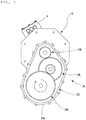
Fig. 2 is a plan view of the embodiment inFig. 1 . -
Fig. 3 is an end view of a gear train in the embodiment inFig. 1 when viewed from a direction of a line III-III inFig. 1 . -
Fig. 4 is a partial sectional view which shows helical directions of helical gears in a left-hand side gear train inFig. 1 . -
Fig. 5 is a schematic plan view which shows an electric vehicle utilizing the two-motor vehicle-driving apparatus according to the present invention. -
Fig. 6 is a cross-sectional plan view which shows an example of conventional two-motor vehicle-driving apparatus. -
Fig. 7 is a cross-sectional plan view which shows a two-motor vehicle driving apparatus having a three-piece-structure speed reducer casing which utilizes the conventional combination of helix directions in their helical gears. -
Fig. 8 is a plan view of the apparatus inFig. 7 . - Hereinafter, embodiments of the present invention will be described based on the attached drawings.
- As shown in
Fig. 1 andFig. 2 , a two-motor vehicle-driving apparatus A according to the present invention utilizes a structure that aspeed reducer casing 20, which houses twospeed reducers motor casings electric motors speed reducer casing 20. - As shown in
Fig. 5 , an electric vehicle B is a rear-wheel drive type, and includes achassis 51;front wheels 52 as steering wheels;rear wheels 53 as driving wheels; and the two-motor vehicle-driving apparatus A which drives the left and the rightrear wheels 53 independently from each other. The two-motor vehicle-driving apparatus A is mounted on thechassis 51, at a center position between the left and the rightrear wheels 53. Driving power from the two-motor vehicle-driving apparatus A are transmitted to therear wheels 53 viaconstant velocity joints 15 andintermediate shafts 16. At a center of thechassis 51, there is placed aninverter 9 which supplies electric power to the two-motor vehicle driving apparatus A. - It should be noted here that the two-motor vehicle driving apparatus A is also applicable, in addition to rear wheel drive systems as shown in
Fig. 5 , to front wheel drive systems and four-wheel drive systems. - As shown in
Fig. 1 andFig. 2 , the left and the rightelectric motors motor casings - As shown in
Fig. 2 , themotor casings electric motors terminal boxes 5, into which three-phaseUVW power lines 4 are extended out of the left and right motor casings. - The
motor casings speed reducers motor shafts 12a to extend therefrom. - As shown in
Fig. 1 , theelectric motors stator 11, and thestator 11 has its inner circumference opposed by arotor 12 at a distance. It should be noted here that theelectric motors - The
rotor 12 has amotor shaft 12a through its center. Themotor shaft 12a extends out of the openings formed in the inboard walls 3cL, 3cR of the motor casing main bodies 3aL, 3aR toward thespeed reducers Seal members 13 are placed between respective openings in the inboard walls 3cL, 3cR of the motor casing main bodies 3aL, 3aR and themotor shafts 12a. - The
motor shafts 12a are rotatably supported by the inboard walls 3cL, 3cR and outboard walls 3bL, 3bR of the motor casing main bodies 3aL, 3aR via rollingbearings Fig. 1 ). - As shown in
Fig. 1 andFig. 2 , thespeed reducer casing 20, which houses the twospeed reducers center casing 20a, and a left and a right side casings 20bL, 20bR which are fixed to respective sides of thecenter casing 20a. As shown inFig. 2 , the left and right side casings 20bL, 20bR are fixed onto two side openings in thecenter casing 20a, with a plurality ofbolts - By utilizing a plurality of
bolts 29 to fix outboard side surfaces of the side casings 20bL, 20bR of thespeed reducer casing 20 and the inboard walls 3cL, 3cR of the motor casing main bodies 3aL, 3aR of theelectric motor electric motors Fig. 1 andFig. 2 ) . - As shown in
Fig. 1 , thecenter casing 20a has apartition wall 21 at its center. Thespeed reducer casing 20 is divided into two, i.e., a left and a right portions, by thepartition wall 21, to provide a left-hand side and a right-hand side storage chambers side by side to house the twospeed reducers - As shown in
Fig. 1 , thespeed reducers input gear shafts motor shafts 12a;intermediate gear shafts diameter gears 24a for engagement with the input gears 23a, and small-diameter gears 24b for engagement withoutput gears 25a; andoutput gear shafts output gears 25a, extend out of thespeed reducer casing 20 and transmit driving power to the driving wheels via constant velocity joints 15 and intermediate shafts 16 (Fig. 5 ). The left and rightinput gear shafts intermediate gear shafts output gear shafts - In the two-motor vehicle driving apparatus A, each of the
gears gear shafts speed reducers gear shafts speed reducer casing 20 via rolling bearings. - In the helical gear, gear teeth are skewed with respect to the gear shaft, and this causes a force generated in an axial direction (thrust direction) when driving power is transmitted.
- Directions of the forces in the thrust direction generated by the helical gears in the two-motor vehicle driving apparatus A according to the present invention during forward driving are shown in
Fig. 1 using arrows. -
Fig. 3 shows an end view taken from a direction of a line III-III inFig. 1 , with an arrow indicating a rotating direction of theoutput gear shaft 25L. The vehicle's forward direction is an upward direction inFig. 3 . Theoutput gear shaft 25L rotates clockwise. - As shown in
Fig. 1 , in the two-motor vehicle driving apparatus A according to the present invention, in each of thehelical gears gear shafts speed reducer output gear shafts -
Fig. 4 shows the helical gears' helix directions for the gear train in the left-handside speed reducer 2L of the twospeed reducers input gear 23a of theinput gear shaft 23L has a right-hand helix; the large-diameter gear 24a of theintermediate gear shaft 24L has a left-hand helix; the small-diameter gear 24b of theintermediate gear shaft 24L has a left-hand helix; and theoutput gear 25a of theoutput gear shaft 25L has a right-hand helix. Both of the large-diameter gear 24a and the small-diameter gear 24b of theintermediate gear shaft 24L have a left-hand helix. -
Fig. 1 shows directions of the thrust directional forces (f1, f2, f3) generated by thehelical gears - Since the
intermediate gear shafts diameter gear 24a which makes engagement with the input gears 23a of theinput gear shafts output gear shafts - In the two, left and right speed reducers 2, i.e., in the right-hand side drivetrain and the left-hand side drivetrain, the helical gear's helical direction is selected so that the directions of the two f3 forces will be symmetrical with each other; specifically, so that both of the left and the right f3 forces are outward.
- In addition, in the two, left and
right speed reducers output gear shafts - The output gears 25a of the
output gear shafts
the final-stage gear in the drivetrains, therefore receive a large load torque, and accordingly generates large forces in the thrust direction in the inward direction during the forward drive. - As described, inward forces in the thrust direction is generated in the output gears 25a of the
output gear shafts speed reducer casing 20 which has a three-piece structure including thecenter casing 20a and the left and the right, side casings 20bL, 20bR fixed to the two side surfaces of thecenter casing 20a. In the left and the right gear trains, both of the last-stage output gears 25a generate large inward thrust forces and therefore, none of the left and the right, side casings 20bL, 20bR receives a force in the direction separating from thecenter casing 20a. - In the
center casing 20a and each of the left and right side casings 20bL, 20bR, for a purpose of preventing lubrication oil from leaking from inside thespeed reducer casing 20 or preventing muddy water from making entry from outside into thespeed reducer casing 20, a sealing structure such as an O ring and liquid-form gasket is provided between contact surfaces of thecenter casing 20a and each of the left and right side casings 20bL, 20bR. Thecenter casing 20a and the left and right side casings 20bL, 20bR are fixed to each other by fastening withbolts Fig. 2 ). - In the case where the helix direction in each of the
helical gears - It should be noted here that when the electric motors are utilized as electric generators in reverse travel (rearward coasting), thrust forces will be generated in the inward direction like in the forward driving in which driving power is supplied by the electric motors, due to helix directions of the output gears 25a and direction of circumferential forces exerted onto tooth flank.
- On the first stage, i.e., the
input gear shafts intermediate gear shafts input gear shafts intermediate gear shafts diameter gears 24a and the small-diameter gear 24b generate thrust forces (f1, f2) in mutually opposing directions to partially canceling the forces, so resulting thrust forces are small. Hence, in comparison with the conventional gear configuration in which outward thrust forces (f2) are generated by the output gears 25a of theoutput gear shafts speed reducer casings 20 are smaller. - Therefore, it is possible to decrease the number of
bolts center casing 20a and the left and right side casings 20bL, 20bR; to reduce increase in screw hole machining cost and parts cost; and to decrease weight and size. - The
input gear shaft fitting holes 27a formed in two surfaces, i.e., a left and a right surfaces, of thepartition wall 21 of thecenter casing 20a and by bearingfitting holes 27b formed in each of the side casings 20bL, 20bR, via rollingbearings - The
input gear shafts openings 27c formed in the side casings 20bL, 20bR. Anoil seal 31 is provided between each pair of theopening 27c and outboard end of theinput gear shafts speed reducers - The
input gear shaft motor shafts 12a are inserted through these hollowinput gear shafts input gear shafts motor shafts 12a are connected with each other by means of spline connection (including serration connection). - The
intermediate gear shafts diameter gear 24a for engagement with theinput gear 23a; and the small-diameter gear 24b for engagement with theoutput gear 25a. In theseintermediate gear shafts diameter gears 24a which make engagement with the input gears 23a, and the small-diameter gears 24b which make engagement with the output gears 25a, have the same helix direction as shown inFig, 4 . - The
intermediate gear shaft fitting holes 32a formed in two surfaces of thepartition wall 21 of thecenter casing 20a and by bearingfitting holes 32b formed in each of the side casings 20bL, 20bR, via rollingbearings - The
output gear shaft diameter output gear 25a, are supported by bearingfitting holes 35a formed in two surfaces of thepartition wall 21 of thecenter casing 20a and by bearingfitting holes 35b formed in each of the side casings 20bL, 20bR, via rollingbearings - The
output gear shafts openings 35c formed in the side casings 20bL, 20bR, out of thespeed reducer casing 20. Outerjoint members 15a of a constant velocity joint 15 are connected by means of spline connection (including serration connection) to outer circumferential surfaces of the outboard ends of the extendedoutput gear shaft - The constant velocity joints 15 connected with the
output gear shafts Fig. 5 ). - Oil seals 39 are provided between each pair of outboard end of the
output gear shaft opening 35c which are formed in the side casings 20bL, 20bR, to prevent lubrication oil from leaking from inside thespeed reducers - The
input gear shafts intermediate gear shafts output gear shafts right speed reducers - The present invention is in no way limited by the embodiments described above, and is needless to say possible to implement in various other ways within the scope of the present invention. The scope of the present invention is described by CLAIMS and includes all variation within equivalent meaning and scope of the CLAIMS.
-
- 1L, 1R : Electric Motors
- 2L, 2R : Speed Reducers
- 3L, 3R : Motor Casing
- 3aL, 3aR : Motor Casing Main Bodies
- 3bL, 3bR : Outward Walls
- 3cL, 3cR : Inboard walls
- 4 : Power Line
- 5 : Terminal box
- 9 : Inverter
- 11 : Stator
- 12 : Rotor
- 12a : Motor Shaft
- 13 :Seal Member
- 14a, 14b : Rolling Bearings
- 15 : Constant Velocity Joint
- 15a : Outer Joint Member
- 16 : Intermediate Shaft
- 20 : Speed Reducer Casing
- 20a : Center Casing
- 20bL, 20bR : Side Casings
- 21 : Partition Wall
- 23L, 23R : Input Gear Shafts
- 23a : Input Gear
- 24L, 24R : Intermediate Gear Shafts
- 24a : Large-Diameter Gear
- 24b : Small-Diameter Gear
- 25L, 25R : Output Gear Shafts
- 25a : Output Gear
- 26L, 26R : Bolts
- 27a, 27b : bearing Fitting Holes
- 27c : Opening
- 28a, 28b : Rolling Bearings
- 29 : Bolt
- 31 : Oil Seals
- 32a, 32b : Bearing Fitting Holes
- 34a, 34b : Rolling Bearings
- 35a, 35b : Bearing Fitting Holes
- 35c : Opening
- 37a, 37b : Rolling Bearings
- 39 :Oil Seal
- 51 : Chassis
- 52 : Front Wheel
- 53 :Rear Wheel
- A : Two-Motor Vehicle Driving Apparatus
- B : Electric Vehicle
- f1, f2, f3 : Force Directions
Claims (4)
- A two-motor vehicle driving apparatus comprising: two electric motors for driving a left and a right driving wheels independently from each other; and two speed reducers for individually reducing and then transmitting powers from the two electric motors to the left and the right driving wheels; the two speed reducers are housed side by side on left and right in a speed reducer casing disposed at a center, with two motor casings fixed respectively on left and right thereof each for housing an electric motor therein; each of the two speed reducers is provided by a parallel-gear speed reducer including an input gear shaft having an input gear for receiving driving power from a motor shaft, an output gear shaft having an output gear for transmitting drive power to the drive wheel via a drive shaft, and an intermediate gear shaft having a large-diameter gear for engagement with the input gear and a small-diameter gear for engagement with the output gear are disposed in parallel with each other; each gear on each gear shaft is provided by a helical gear; the speed reducer casing which houses the two speed reducers side by side on left and right has a three-piece structure consisting of a center casing and a left and a right side casings fixed onto two side surfaces of the center casing; wherein directions of helix in the helical gears on each gear shaft are selected so that the helical gears which work as the output gears of the output gear shafts generates inward thrust forces when the electric motors are driving the vehicle in a forward direction.
- The two-motor vehicle driving apparatus according to Claim 1, wherein the helical gears on the intermediate gear shaft, i.e. one serving as the large-diameter gear for engagement with the input gear and the other serving as the small-diameter gear for engagement with the output gear, have a same helix direction.
- The two-motor vehicle driving apparatus according to Claim 1 or 2, wherein the center casing which serves as the speed reducer casing for housing the two speed reducers side by side on left and right, and the left and the right side casings which are fixed onto two side surfaces of the center casing are bolted with each other.
- The two-motor vehicle driving apparatus according to one of Claims 1 through 3, wherein the center casing which serves as the speed reducer casing for housing the two speed reducers side by side on left and right, and the left and the right side casings which are fixed onto two side surfaces of the center casing have their mutually contacting surfaces provided with a seal structure such as an O ring and liquid gasket.
Applications Claiming Priority (2)
| Application Number | Priority Date | Filing Date | Title |
|---|---|---|---|
| JP2015085955A JP6453700B2 (en) | 2015-04-20 | 2015-04-20 | Two-motor vehicle drive device |
| PCT/JP2016/062238 WO2016171100A1 (en) | 2015-04-20 | 2016-04-18 | Two-motor vehicle drive device |
Publications (2)
| Publication Number | Publication Date |
|---|---|
| EP3287666A1 true EP3287666A1 (en) | 2018-02-28 |
| EP3287666A4 EP3287666A4 (en) | 2019-01-16 |
Family
ID=57144630
Family Applications (1)
| Application Number | Title | Priority Date | Filing Date |
|---|---|---|---|
| EP16783121.3A Withdrawn EP3287666A4 (en) | 2015-04-20 | 2016-04-18 | Two-motor vehicle drive device |
Country Status (5)
| Country | Link |
|---|---|
| US (1) | US10207572B2 (en) |
| EP (1) | EP3287666A4 (en) |
| JP (1) | JP6453700B2 (en) |
| CN (1) | CN107636357A (en) |
| WO (1) | WO2016171100A1 (en) |
Cited By (5)
| Publication number | Priority date | Publication date | Assignee | Title |
|---|---|---|---|---|
| EP3663118A1 (en) * | 2018-12-04 | 2020-06-10 | AVL MTC Motortestcenter AB | Transmission arrangement for a drive system of a vehicle |
| US20220048375A1 (en) * | 2019-03-06 | 2022-02-17 | Mitsubishi Jidosha Kogyo Kabushiki Kaisha | Left-right wheel driving device |
| DE102020128930A1 (en) | 2020-11-03 | 2022-05-05 | Dr. Ing. H.C. F. Porsche Aktiengesellschaft | Drive unit for an electric vehicle |
| FR3145959A1 (en) | 2023-02-22 | 2024-08-23 | Nidec Psa Emotors | Reduction unit for motor vehicle |
| FR3157847A1 (en) | 2023-12-29 | 2025-07-04 | Ampere Sas | Method for improving target selection for adaptive speed control |
Families Citing this family (23)
| Publication number | Priority date | Publication date | Assignee | Title |
|---|---|---|---|---|
| JP6453700B2 (en) * | 2015-04-20 | 2019-01-16 | Ntn株式会社 | Two-motor vehicle drive device |
| DE102016006536B4 (en) * | 2016-05-27 | 2018-03-15 | Audi Ag | Electric drive unit for a wheel of a motor vehicle and wheel suspension for the wheels of an axle of a motor vehicle |
| CN107763143B (en) * | 2017-11-24 | 2024-06-14 | 厦门市福工动力技术有限公司 | Speed reducer for electric automobile |
| JP6954114B2 (en) * | 2017-12-28 | 2021-10-27 | 株式会社アイシン | Vehicle drive |
| JP7053405B2 (en) * | 2018-08-17 | 2022-04-12 | Ntn株式会社 | Vehicle drive |
| KR102111472B1 (en) * | 2018-11-08 | 2020-05-15 | 김만식 | Reduction gear for electric vehicle |
| US12007008B2 (en) | 2019-03-28 | 2024-06-11 | Mitsubishi Jidosha Kogyo Kabushiki Kaisha | Left-right wheel driving device |
| EP3973210A1 (en) * | 2019-07-09 | 2022-03-30 | hofer powertrain innovation GmbH | Double gearbox |
| DE102020118194A1 (en) * | 2019-07-09 | 2021-01-14 | Hofer Powertrain Innovation Gmbh | Twin gearbox with a double input shaft |
| DE202019103781U1 (en) * | 2019-07-09 | 2020-10-12 | Hofer Powertrain Innovation Gmbh | Twin gearbox with a double input shaft |
| JP7437406B2 (en) * | 2019-08-29 | 2024-02-22 | 株式会社アイシン | Vehicle drive system |
| US11635130B2 (en) | 2020-06-04 | 2023-04-25 | Rivian Ip Holdings, Llc | Electric vehicle powertrain assembly having nested shafts |
| US11628713B2 (en) * | 2020-06-04 | 2023-04-18 | Rivian Ip Holdings, Llc | Electric vehicle powertrain assembly having nested shafts |
| DE102021200280A1 (en) | 2021-01-14 | 2022-07-14 | Zf Friedrichshafen Ag | Driving device for an electrically driven vehicle |
| JP7477717B2 (en) * | 2021-03-30 | 2024-05-01 | 株式会社アイシン | Vehicle drive device |
| CN113124129A (en) * | 2021-04-13 | 2021-07-16 | 泰兴市康森爱特传动设备科技有限公司 | New forms of energy double round stand alone type driven gearbox for driving more |
| JP7447920B2 (en) | 2022-01-12 | 2024-03-12 | トヨタ自動車株式会社 | Vehicle drive system |
| JP2023144733A (en) * | 2022-03-28 | 2023-10-11 | 住友電装株式会社 | vehicle structure |
| JP7819608B2 (en) * | 2022-11-10 | 2026-02-25 | トヨタ自動車株式会社 | Drive force transmission device |
| DE102023101506A1 (en) | 2023-01-23 | 2024-07-25 | Bayerische Motoren Werke Aktiengesellschaft | Gearbox for a coaxial two-machine electric drive of a motor vehicle |
| US20240336121A1 (en) * | 2023-04-04 | 2024-10-10 | Toyota Motor Engineering & Manufacturing North America, Inc. | Dual Electric Motor Assembly Systems and Methods |
| KR102597706B1 (en) | 2023-08-01 | 2023-11-02 | 주식회사 엔탑엔지니어링 | High efficiency driving system for vehicle |
| US12594829B2 (en) * | 2023-10-30 | 2026-04-07 | Kubota Corporation | Electric work vehicle |
Family Cites Families (22)
| Publication number | Priority date | Publication date | Assignee | Title |
|---|---|---|---|---|
| JPH0527395U (en) * | 1991-09-20 | 1993-04-09 | 三菱重工業株式会社 | Two-stage reduction gear device using helical gears |
| CN2165286Y (en) * | 1992-09-15 | 1994-05-18 | 武汉煤炭设计研究院 | Double-motor two-speed reducer |
| US6155364A (en) * | 1996-02-21 | 2000-12-05 | Toyota Jidosha Kabushiki Kaisha | Hybrid drive system wherein planetary gear mechanism is disposed radially inwardly of stator coil of motor/generator |
| JPH11243664A (en) * | 1998-02-24 | 1999-09-07 | Honda Motor Co Ltd | Electric drive system for vehicles |
| JP4056614B2 (en) * | 1998-03-20 | 2008-03-05 | 住友重機械工業株式会社 | Parallel shaft gear reducer |
| WO2000032433A1 (en) * | 1998-12-01 | 2000-06-08 | Hitachi, Ltd. | Drive device and vehicle |
| US6117036A (en) * | 1999-07-29 | 2000-09-12 | New Venture Gear, Inc. | Split helical planetary gear assembly |
| JP3859052B2 (en) * | 2000-06-13 | 2006-12-20 | アイシン・エィ・ダブリュ株式会社 | Drive device |
| JP3856085B2 (en) * | 2000-08-01 | 2006-12-13 | 日産自動車株式会社 | Power transmission device for vehicle |
| JP4346059B2 (en) * | 2000-09-08 | 2009-10-14 | 本田技研工業株式会社 | Vehicle transmission |
| CN1194873C (en) * | 2002-08-16 | 2005-03-30 | 于耀庆 | Structure mode of electro-mobile power and driving device |
| JP4060693B2 (en) * | 2002-11-28 | 2008-03-12 | 本田技研工業株式会社 | Motor drive device |
| US6952061B2 (en) * | 2002-11-28 | 2005-10-04 | Honda Motor Co., Ltd | Motor drive unit |
| CN1291855C (en) * | 2002-12-08 | 2006-12-27 | 中国第一汽车集团公司 | Dual-motor hybrid vehicle powertrain |
| JP5117960B2 (en) * | 2008-08-22 | 2013-01-16 | アイシン・エィ・ダブリュ株式会社 | Vehicle drive device |
| EP2416033B1 (en) * | 2009-03-31 | 2018-09-19 | Honda Motor Co., Ltd. | Drive device and vehicle with same |
| JP5290217B2 (en) * | 2010-02-25 | 2013-09-18 | トヨタ自動車株式会社 | Power transmission device for vehicle |
| JP5016076B2 (en) * | 2010-02-25 | 2012-09-05 | トヨタ自動車株式会社 | Power transmission device for vehicle |
| DE102011104279A1 (en) * | 2011-06-10 | 2012-12-13 | Getrag Getriebe- Und Zahnradfabrik Hermann Hagenmeyer Gmbh & Cie Kg | Automotive powertrain |
| JP5579882B2 (en) * | 2013-01-08 | 2014-08-27 | 株式会社マキタ | Reduction mechanism for power tools |
| WO2015183159A1 (en) * | 2014-05-27 | 2015-12-03 | Scania Cv Ab | Gearbox for vehicles and vehicles comprising such a gearbox |
| JP6453700B2 (en) * | 2015-04-20 | 2019-01-16 | Ntn株式会社 | Two-motor vehicle drive device |
-
2015
- 2015-04-20 JP JP2015085955A patent/JP6453700B2/en active Active
-
2016
- 2016-04-18 CN CN201680029416.3A patent/CN107636357A/en active Pending
- 2016-04-18 US US15/568,021 patent/US10207572B2/en not_active Expired - Fee Related
- 2016-04-18 EP EP16783121.3A patent/EP3287666A4/en not_active Withdrawn
- 2016-04-18 WO PCT/JP2016/062238 patent/WO2016171100A1/en not_active Ceased
Cited By (7)
| Publication number | Priority date | Publication date | Assignee | Title |
|---|---|---|---|---|
| EP3663118A1 (en) * | 2018-12-04 | 2020-06-10 | AVL MTC Motortestcenter AB | Transmission arrangement for a drive system of a vehicle |
| US20220048375A1 (en) * | 2019-03-06 | 2022-02-17 | Mitsubishi Jidosha Kogyo Kabushiki Kaisha | Left-right wheel driving device |
| US12240305B2 (en) * | 2019-03-06 | 2025-03-04 | Mitsubishi Jidosha Kogyo Kabushiki Kaisha | Left-right wheel driving device |
| DE102020128930A1 (en) | 2020-11-03 | 2022-05-05 | Dr. Ing. H.C. F. Porsche Aktiengesellschaft | Drive unit for an electric vehicle |
| FR3145959A1 (en) | 2023-02-22 | 2024-08-23 | Nidec Psa Emotors | Reduction unit for motor vehicle |
| WO2024175838A1 (en) | 2023-02-22 | 2024-08-29 | Nidec Psa Emotors | Reduction gear assembly for a motor vehicle |
| FR3157847A1 (en) | 2023-12-29 | 2025-07-04 | Ampere Sas | Method for improving target selection for adaptive speed control |
Also Published As
| Publication number | Publication date |
|---|---|
| JP6453700B2 (en) | 2019-01-16 |
| US10207572B2 (en) | 2019-02-19 |
| CN107636357A (en) | 2018-01-26 |
| WO2016171100A1 (en) | 2016-10-27 |
| EP3287666A4 (en) | 2019-01-16 |
| US20180141423A1 (en) | 2018-05-24 |
| JP2016205488A (en) | 2016-12-08 |
Similar Documents
| Publication | Publication Date | Title |
|---|---|---|
| US10207572B2 (en) | Two-motor vehicle drive device | |
| EP3260736B1 (en) | Two-motor vehicle drive device | |
| US11155161B2 (en) | Motor drive device for automobile and equipped with speed reducer | |
| JP6560009B2 (en) | Two-motor vehicle drive device | |
| EP3456568A1 (en) | Modular electric drive axle | |
| EP3345778A1 (en) | Electric vehicle | |
| JP6670118B2 (en) | Vehicle drive | |
| JP6518106B2 (en) | Motor drive with reduction gear for automobile | |
| EP3418607A1 (en) | Vehicle-driving apparatus | |
| JP2017158377A (en) | Vehicle driving device with two motor | |
| US9950609B2 (en) | Power generation device | |
| WO2017051746A1 (en) | Vehicle drive device | |
| US20070213166A1 (en) | Double Differential Assembly | |
| JP2018039396A (en) | Two motor vehicle drive device | |
| JP2017061959A (en) | Vehicle drive unit | |
| JP2016180424A (en) | Vehicle driving device | |
| US9914357B1 (en) | Differential carrier with integrated drive gear and method of making the same | |
| JP6222074B2 (en) | Vehicle drive device | |
| JP6217660B2 (en) | Vehicle drive device | |
| JP2008164123A (en) | Power transmission device | |
| JP2016188651A (en) | Two-motor vehicle drive device | |
| JP2018048686A (en) | Vehicle driving device | |
| JP2018048670A (en) | Vehicle drive device | |
| JP6202011B2 (en) | Vehicle drive device | |
| JP6647935B2 (en) | Planetary gear device and vehicle drive device using the same |
Legal Events
| Date | Code | Title | Description |
|---|---|---|---|
| PUAI | Public reference made under article 153(3) epc to a published international application that has entered the european phase |
Free format text: ORIGINAL CODE: 0009012 |
|
| 17P | Request for examination filed |
Effective date: 20171116 |
|
| AK | Designated contracting states |
Kind code of ref document: A1 Designated state(s): AL AT BE BG CH CY CZ DE DK EE ES FI FR GB GR HR HU IE IS IT LI LT LU LV MC MK MT NL NO PL PT RO RS SE SI SK SM TR |
|
| AX | Request for extension of the european patent |
Extension state: BA ME |
|
| DAV | Request for validation of the european patent (deleted) | ||
| DAX | Request for extension of the european patent (deleted) | ||
| A4 | Supplementary search report drawn up and despatched |
Effective date: 20181219 |
|
| RIC1 | Information provided on ipc code assigned before grant |
Ipc: F16H 1/08 20060101ALI20181213BHEP Ipc: B60K 17/14 20060101ALI20181213BHEP Ipc: F16H 57/023 20120101AFI20181213BHEP Ipc: B60K 1/02 20060101ALI20181213BHEP Ipc: H02K 7/116 20060101ALI20181213BHEP Ipc: B60K 7/00 20060101ALI20181213BHEP |
|
| STAA | Information on the status of an ep patent application or granted ep patent |
Free format text: STATUS: THE APPLICATION HAS BEEN WITHDRAWN |
|
| 18W | Application withdrawn |
Effective date: 20200225 |