EP3287630A1 - Gas turbine engine with cold turbine and multiple core flowpaths - Google Patents
Gas turbine engine with cold turbine and multiple core flowpaths Download PDFInfo
- Publication number
- EP3287630A1 EP3287630A1 EP17187812.7A EP17187812A EP3287630A1 EP 3287630 A1 EP3287630 A1 EP 3287630A1 EP 17187812 A EP17187812 A EP 17187812A EP 3287630 A1 EP3287630 A1 EP 3287630A1
- Authority
- EP
- European Patent Office
- Prior art keywords
- rotor
- airflow
- flowpath
- turbine
- cold
- Prior art date
- Legal status (The legal status is an assumption and is not a legal conclusion. Google has not performed a legal analysis and makes no representation as to the accuracy of the status listed.)
- Granted
Links
- 239000000654 additive Substances 0.000 claims description 2
- 230000000996 additive effect Effects 0.000 claims description 2
- 238000011144 upstream manufacturing Methods 0.000 description 9
- 238000002485 combustion reaction Methods 0.000 description 3
- 239000000203 mixture Substances 0.000 description 2
- RZVHIXYEVGDQDX-UHFFFAOYSA-N 9,10-anthraquinone Chemical compound C1=CC=C2C(=O)C3=CC=CC=C3C(=O)C2=C1 RZVHIXYEVGDQDX-UHFFFAOYSA-N 0.000 description 1
- 230000000712 assembly Effects 0.000 description 1
- 238000000429 assembly Methods 0.000 description 1
- 230000006835 compression Effects 0.000 description 1
- 238000007906 compression Methods 0.000 description 1
- 239000000446 fuel Substances 0.000 description 1
- 238000002955 isolation Methods 0.000 description 1
- 238000000034 method Methods 0.000 description 1
- 230000037361 pathway Effects 0.000 description 1
- 238000005096 rolling process Methods 0.000 description 1
- 230000001953 sensory effect Effects 0.000 description 1
Images


Classifications
-
- F—MECHANICAL ENGINEERING; LIGHTING; HEATING; WEAPONS; BLASTING
- F02—COMBUSTION ENGINES; HOT-GAS OR COMBUSTION-PRODUCT ENGINE PLANTS
- F02K—JET-PROPULSION PLANTS
- F02K3/00—Plants including a gas turbine driving a compressor or a ducted fan
- F02K3/02—Plants including a gas turbine driving a compressor or a ducted fan in which part of the working fluid by-passes the turbine and combustion chamber
- F02K3/04—Plants including a gas turbine driving a compressor or a ducted fan in which part of the working fluid by-passes the turbine and combustion chamber the plant including ducted fans, i.e. fans with high volume, low pressure outputs, for augmenting the jet thrust, e.g. of double-flow type
- F02K3/06—Plants including a gas turbine driving a compressor or a ducted fan in which part of the working fluid by-passes the turbine and combustion chamber the plant including ducted fans, i.e. fans with high volume, low pressure outputs, for augmenting the jet thrust, e.g. of double-flow type with front fan
-
- F—MECHANICAL ENGINEERING; LIGHTING; HEATING; WEAPONS; BLASTING
- F02—COMBUSTION ENGINES; HOT-GAS OR COMBUSTION-PRODUCT ENGINE PLANTS
- F02C—GAS-TURBINE PLANTS; AIR INTAKES FOR JET-PROPULSION PLANTS; CONTROLLING FUEL SUPPLY IN AIR-BREATHING JET-PROPULSION PLANTS
- F02C3/00—Gas-turbine plants characterised by the use of combustion products as the working fluid
- F02C3/04—Gas-turbine plants characterised by the use of combustion products as the working fluid having a turbine driving a compressor
- F02C3/10—Gas-turbine plants characterised by the use of combustion products as the working fluid having a turbine driving a compressor with another turbine driving an output shaft but not driving the compressor
-
- F—MECHANICAL ENGINEERING; LIGHTING; HEATING; WEAPONS; BLASTING
- F02—COMBUSTION ENGINES; HOT-GAS OR COMBUSTION-PRODUCT ENGINE PLANTS
- F02K—JET-PROPULSION PLANTS
- F02K3/00—Plants including a gas turbine driving a compressor or a ducted fan
- F02K3/02—Plants including a gas turbine driving a compressor or a ducted fan in which part of the working fluid by-passes the turbine and combustion chamber
- F02K3/04—Plants including a gas turbine driving a compressor or a ducted fan in which part of the working fluid by-passes the turbine and combustion chamber the plant including ducted fans, i.e. fans with high volume, low pressure outputs, for augmenting the jet thrust, e.g. of double-flow type
- F02K3/075—Plants including a gas turbine driving a compressor or a ducted fan in which part of the working fluid by-passes the turbine and combustion chamber the plant including ducted fans, i.e. fans with high volume, low pressure outputs, for augmenting the jet thrust, e.g. of double-flow type controlling flow ratio between flows
-
- F—MECHANICAL ENGINEERING; LIGHTING; HEATING; WEAPONS; BLASTING
- F02—COMBUSTION ENGINES; HOT-GAS OR COMBUSTION-PRODUCT ENGINE PLANTS
- F02K—JET-PROPULSION PLANTS
- F02K3/00—Plants including a gas turbine driving a compressor or a ducted fan
- F02K3/02—Plants including a gas turbine driving a compressor or a ducted fan in which part of the working fluid by-passes the turbine and combustion chamber
- F02K3/04—Plants including a gas turbine driving a compressor or a ducted fan in which part of the working fluid by-passes the turbine and combustion chamber the plant including ducted fans, i.e. fans with high volume, low pressure outputs, for augmenting the jet thrust, e.g. of double-flow type
- F02K3/077—Plants including a gas turbine driving a compressor or a ducted fan in which part of the working fluid by-passes the turbine and combustion chamber the plant including ducted fans, i.e. fans with high volume, low pressure outputs, for augmenting the jet thrust, e.g. of double-flow type the plant being of the multiple flow type, i.e. having three or more flows
Definitions
- This disclosure relates generally to a gas turbine engine and, more particularly, to a gas turbine engine with multiple core flowpaths.
- a gas turbine engine includes a spool and a cold turbine inlet passage.
- the spool is configured to rotate about an axial centerline.
- the spool includes a fan rotor and a cold turbine rotor.
- the fan rotor is rotatably driven by the cold turbine rotor.
- the cold turbine inlet passage is configured to direct an airflow along a radial inward trajectory to the cold turbine rotor.
- another gas turbine engine includes a fan section, a first turbine section, a compressor section, a second turbine section and a combustor.
- the fan section includes a fan rotor.
- the first turbine section includes a first turbine rotor configured to drive the fan rotor.
- the compressor section includes a compressor rotor.
- the second turbine section includes a second turbine rotor configured to drive the compressor rotor.
- the gas turbine engine is configured with a first flowpath and a second flowpath.
- the first flowpath is downstream of the compressor section and extends through the first turbine section.
- the second flowpath is downstream of the compressor section and extends respectively through the combustor and the second turbine section.
- the gas turbine engine may include a cold turbine outlet passage.
- the cold turbine rotor may be configured to: (a) receive the airflow from the cold turbine inlet passage along the radial inward trajectory; and (b) direct the airflow into the cold turbine outlet passage along an axial trajectory.
- the gas turbine engine may include an airflow regulator configured to regulate the airflow through the cold turbine rotor.
- the airflow regulator may be configured downstream of the cold turbine rotor.
- the airflow regulator may include a door.
- the gas turbine engine may include a second spool and a combustor.
- the second spool may include a compressor rotor and a hot turbine rotor.
- the combustor may be fluidly between the compressor rotor and the hot turbine rotor.
- the gas turbine engine may include a first flowpath, a second flowpath and a manifold.
- the first flowpath may extend through the cold turbine rotor.
- the second flowpath may extend through the combustor and the hot turbine rotor.
- the manifold may be configured to receive a compressed airflow from the compressor rotor, to direct a portion of the compressed airflow into the first flowpath as the airflow, and to direct another portion of the compressed airflow into the second flowpath as a second airflow.
- the manifold may include the cold turbine inlet passage.
- the manifold may include an annular array of ports, which includes a plurality of first ports and a plurality of second ports. Each of the first ports may be located between an adjacent pair of the second ports. The first ports may be fluidly coupled with the first flowpath. The second ports may be fluidly coupled with the second flowpath.
- the manifold may be formed as a monolithic body.
- the manifold may be additive manufactured.
- the combustor may be configured as or otherwise include a reverse flow combustor.
- the hot turbine rotor may be configured to receive a second airflow along a radial inward trajectory, and to output the second airflow along an axial trajectory.
- the spool may substantially only include the fan rotor, the cold turbine rotor and a shaft connecting the fan rotor and the cold turbine rotor.
- the gas turbine engine may include a first spool comprising the fan rotor and the first turbine rotor.
- the gas turbine engine may also include a second spool comprising the compressor rotor and the second turbine rotor.
- the gas turbine engine may be configured with a third flowpath that extends through the fan section and bypasses the compressor section, the first turbine section and the second turbine section.
- An outlet of the first flowpath may be fluidly coupled with the third flowpath.
- the cold turbine rotor may be configured to receive an airflow along a radial inward trajectory, and to output the airflow along an axial trajectory.
- the gas turbine engine may include a manifold configured to receive a compressed airflow from the compressor rotor, to direct a portion of the compressed airflow into the first flowpath as a first airflow, and to direct another portion of the compressed airflow into the second flowpath as a second airflow.
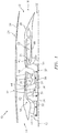
- FIG. 1 is a partial side sectional schematic illustration of a multi-stream mixed turbofan gas turbine engine 10 for an aircraft propulsion system.
- This turbine engine 10 extends along an axial centerline 12 from a forward and upstream airflow inlet 14 to an aft and downstream airflow exhaust 16.
- the turbine engine 10 includes a compressor section 18, a fan section 19, a cold turbine section 20, a hot turbine section 21 and a combustor section 22.
- an airflow is directed through the compressor section 18 to an airflow manifold 44.
- the manifold 44 splits the compressed airflow and directs a portion of the split airflow through the cold turbine section 20, which thereby powers the fan section 19.
- the manifold 44 also directs another portion of the split airflow through the combustor section 22 and then the hot turbine section 21, which thereby powers the compressor section 18.
- the engine sections 18-22 may be arranged sequentially along the centerline 12, and are arranged within an engine housing 24.
- This engine housing 24 includes an inner housing structure 26 and an outer housing structure 28.
- the inner housing structure 26 of FIG. 1 houses the compressor section 18, the cold turbine section 20, the combustor section 22 and the hot turbine section 21.
- the outer housing structure 28 of FIG. 1 houses the fan section 19 and circumscribes the inner housing structure 26.
- the compressor section 18, the fan section 19, the cold turbine section 20 and the hot turbine section 21 each include a respective rotor 30-33.
- Each of these rotors 30-33 includes a plurality of rotor blades arranged circumferentially around and connected to one or more respective rotor disks.
- the rotor blades may be formed integral with or mechanically fastened, welded, brazed, adhered and/or otherwise attached to the respective rotor disk(s).
- the compressor rotor 30 and/or the fan rotor 31 may each be configured as an axial flow rotor.
- the term "axial flow rotor” may describe a rotor configured to (i) receive an incoming airflow along a substantially axial (e.g., more axial than radial) trajectory and (ii) provide an outgoing (e.g., compressed) airflow along the same or a similar substantially axial trajectory. An airflow therefore may travel axially through an axial flow rotor such that an axial trajectory of the airflow is generally unaltered.
- the cold turbine rotor 32 and/or the hot turbine rotor 33 may each be configured as a radial-to-axial flow rotor.
- the term "radial-to-axial flow rotor” may describe a rotor configured to (i) receive an incoming airflow along a substantially radial (e.g., more radial than axial) trajectory and (ii) provide an outgoing airflow along a substantially axial (e.g., more axial than radial) trajectory.
- a course of an airflow therefore may be diverted from a radial inward trajectory to an axial trajectory (e.g., downstream) as that airflow travels through a radial-to-axial flow rotor.
- each of the turbine rotors 32 and 33 of FIG. 1 may be thought of as having an inverse centrifugal rotor / impeller configuration.
- the compressor rotor 30 is connected to and rotatably driven by the hot turbine rotor 33 through an engine shaft 36; e.g., a high speed shaft.
- the turbine engine components 30, 33 and 36 are included in and form an engine spool 37; e.g., a high speed spool.
- the fan rotor 31 is connected to and rotatably driven (e.g., only) by the cold turbine rotor 32 through another engine shaft 38; e.g., a low speed shaft.
- the turbine engine components 31, 32 and 38 are included in and form another engine spool 39; e.g., a low speed spool.
- This engine spool 39 circumscribes and may be substantially coaxial with the engine spool 37.
- the engine shafts 36 and 38 and, thus, the engine spools 37 and 39 are rotatably supported by a plurality of bearings (not shown); e.g., rolling element and/or thrust bearings.
- bearings e.g., rolling element and/or thrust bearings.
- Each of these bearings is connected to the engine housing 24 by at least one stationary structure such as, for example, an annular support strut.
- the turbine engine 10 is configured with a plurality of airflow flowpaths 40-43 and the airflow manifold 44. These flowpaths include a bypass flowpath 40, an upstream core flowpath 41 and a plurality of downstream core flowpaths 42 and 43.
- the bypass flowpath 40 is formed in an annulus radially between the inner housing structure 26 and the outer housing structure 28 and, thereby, bypasses a core portion of the turbine engine 10.
- the bypass flowpath 40 extends from the airflow inlet 14, through the fan section 19, to a nozzle 46 at (e.g., on, adjacent or proximate) the airflow exhaust 16.
- the upstream core flowpath 41 is configured within the inner housing structure 26.
- the upstream core flowpath 41 extends from the airflow inlet 14, through the compressor section 18, to the manifold 44.
- the manifold 44 is fluidly coupled with and between the upstream core flowpath 41 and the downstream core flowpaths 42 and 43.
- the first downstream core flowpath 42 is configured within the inner housing structure 26.
- the first downstream core flowpath 42 extends from the manifold 44, through the cold turbine section 20, to an outlet 48.
- This outlet 48 may be configured in the inner housing structure 26, and fluidly coupled with the bypass flowpath 40 between the fan section 19 and the airflow exhaust 16.
- the second downstream core flowpath 43 is also configured within the inner housing structure 26.
- the second downstream core flowpath 43 extends from the manifold 44, sequentially through the combustor section 22 and the hot turbine section 21, to a nozzle 50 at (e.g., on, adjacent or proximate) the airflow exhaust 16.
- the manifold 44 is fluidly coupled with and between the upstream core flowpath 41 and the downstream core flowpaths 42 and 43.
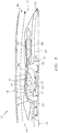
- the manifold 44 is configured to receive a compressed airflow from the upstream core flowpath 41 and split that received compressed airflow into at least a first airflow 52 (see FIG. 2 ) and a second airflow 54 (see FIG. 3 ).
- the manifold 44 is further configured to direct the first airflow 52 into the first downstream core flowpath 42 and direct the second airflow 54 into the second downstream core flowpath 43.
- the first airflow 52 may account for a first portion of the received compressed airflow.
- the second airflow 54 may account for a second portion of the received compressed airflow.
- the second portion may be greater than, less than or substantially equal the first portion depending upon the specific configuration and design requirements of the turbine engine 10.
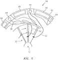
- the manifold 44 includes an inlet passage 56 and a plurality of outlet passages 58 and 60.
- the inlet passage 56 extends from the upstream core flowpath 41 to a manifold structure 62; e.g., an airflow splitter.
- the manifold structure 62 of FIG. 5 is configured with an annular array of ports, which include one or more first ports 64 and one or more second ports 66. Each of the first ports 64 is located circumferentially between an adjacent pair of the second ports 66. Each of the second ports 66 is located circumferentially between an adjacent pair of the first ports 64.
- the first outlet passage 58 which may include one or more conduits / ducts, fluidly couples the first ports 64 with the first downstream core flowpath 42.
- the second outlet passage 60 which may include one or more conduits / ducts, fluidly couples the second ports 66 with the second downstream core flowpath 43.
- the first outlet passage 58 is also configured as a cold turbine inlet passage.
- the first outlet passage 58 for example, is configured to direct the first airflow 52 to the cold turbine rotor 32.
- the first outlet passage 58 is configured to direct the first airflow 52 to and into the cold turbine rotor 32 along a substantially radial inward trajectory.
- the second outlet passage 60 of FIGS. 3 and 4 in contrast, is configured to direct the second airflow 54 towards the combustor section 22 along a substantially axial (and aft) trajectory.
- the manifold 44 may be formed as a monolithic body.
- monolithic may describe a component which is formed as a single unitary body.
- the manifold 44 and each of its components e.g., 56, 58, 60 and 62), for example, may be additively manufactured, cast, machined and/or otherwise formed as a unitary body.
- This monolithic manifold 44 may have a full hoop body, which is formed without any mechanically interconnected axial and/or circumferential segments.
- the present disclosure is not limited to the foregoing exemplary monolithic manifold configuration.
- bypass air a portion of this air is directed into the bypass flowpath 40 and to the fan section 19, which portion of air may be referred to as "bypass air”.
- core air Another portion of the air is directed into the upstream core flowpath 41 and to the compressor section 18, which portion of air may be referred to as "core air”.
- the core air is compressed by the compressor rotor 30 and directed to the manifold 44.
- the manifold 44 directs a first portion of the received compressed core air to the first downstream core flowpath 42 as the first airflow 52.
- This first airflow 52 is directed to and flows through the cold turbine rotor 32, which causes the cold turbine rotor 32 to rotate.
- the rotation of the cold turbine rotor 32 drives rotation of the fan rotor 31, which propels the bypass air through and out of the bypass flowpath 40.
- the first airflow 52 may be combined with the propelled bypass air to increase bypass air thrust.
- the combined bypass airflow and first airflow 52 may be exhausted from the turbine engine 10 through the nozzle 46 at the airflow exhaust 16.
- the manifold 44 also directs a second portion of the received compressed core air to the second downstream core flowpath 43 as the second airflow 54.
- This second airflow 54 is directed into a combustion chamber of a combustor 68 (e.g., a reverse flow combustor) in the combustor section 22.
- Fuel is injected into the combustion chamber and mixed with the second airflow 54 to provide a fuel-air mixture.
- This fuel-air mixture is ignited and combustion products thereof flow through and cause the hot turbine rotor 33 to rotate.
- the rotation of the hot turbine rotor 33 drives rotation of the compressor rotor 30 and, thus, compression of the core airflow.
- the second airflow 54 may be exhausted from the turbine engine 10 through the nozzle 50 at the airflow exhaust 16.
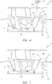
- the turbine engine 10 may include an airflow regulator 70 configured to regulate the first airflow 52 through the first downstream core flowpath 42.
- This regulator 70 may be configured downstream of the cold turbine rotor 32, for example, at (on, adjacent or proximate) the outlet 48.
- the regulator 70 includes one or more doors 72 and is configured as a valve. Each of the doors 72 is configured to move (e.g., pivot or translate) from an open position (see FIG. 7 ) to a partially or completely closed position (see FIG. 6 ), which partially or completely closes the outlet 48.
- the regulator 70 can control operation of the engine spool 39 (see FIG. 1 ).
- the regulator 70 may move one or more of the doors 72 towards or to the open position (see FIG. 7 ).
- the regulator 70 may move one or more of the doors 72 towards or to the closed position (see FIG. 6 ).
- an airflow control system 76 of the engine 10 may facilitate the control of air flow through the first downstream core flowpath 42, and through the bypass flowpath 40, or any combination thereof.
- the control system 76 may include a controller 78 and one or more of the doors 72.
- the controller 78 may receive sensory input and/or operator input, processes the input(s), and output an electronic control signal 80 that operates the doors 72.
- the doors 72 may be any variety of valve-like structures including single-bodied units capable of both pathway isolation and variable flow control.
- the term 'valve' may include a plurality of blocker doors and/or aerodynamically shaped flaps that may be circumferentially distributed and operated by a common sync-ring as one, non-limiting, example.
- the controller 78 may be, for example, part of a flight control computer, a portion of a Full Authority Digital Engine Control (FADEC), a stand-alone unit and/or other system.
- the control module may include a processor, a memory and an interface.
- the processor may be any type of microprocessor having desired performance characteristics.
- the memory may be any computer readable medium that stores data and control algorithms such as logic as described herein. More particularly, the memory is configured to store software (e.g., program instructions) for execution by the processor, which software execution may control and/or facilitate performance of one or more operations such as those described herein.
- the memory may be a non-transitory computer readable medium.
- the interface facilitates communication with other components such as a door actuator.
- the systems and assemblies described above may be included in various aircraft and industrial turbine engines other than the one described above.
- the turbine engine 10, for example, may be configured as a geared or non-geared turbine engine.
- the turbine engine 10 may be configured with more than two spools.
- the turbine engine 10 may include an additional compressor rotor driven by the cold turbine rotor 32. The present disclosure therefore is not limited to the exemplary turbine engine described above.
Landscapes
- Engineering & Computer Science (AREA)
- Chemical & Material Sciences (AREA)
- Combustion & Propulsion (AREA)
- Mechanical Engineering (AREA)
- General Engineering & Computer Science (AREA)
- Structures Of Non-Positive Displacement Pumps (AREA)
Abstract
Description
- This disclosure relates generally to a gas turbine engine and, more particularly, to a gas turbine engine with multiple core flowpaths.
- Various types and configurations of gas turbine engines are known in the art. While these known gas turbine engines have various benefits, there is still room in the art for improvement.
- According to an aspect of the present disclosure, a gas turbine engine is provided that includes a spool and a cold turbine inlet passage. The spool is configured to rotate about an axial centerline. The spool includes a fan rotor and a cold turbine rotor. The fan rotor is rotatably driven by the cold turbine rotor. The cold turbine inlet passage is configured to direct an airflow along a radial inward trajectory to the cold turbine rotor.
- According to another aspect of the present disclosure, another gas turbine engine is provided that includes a fan section, a first turbine section, a compressor section, a second turbine section and a combustor. The fan section includes a fan rotor. The first turbine section includes a first turbine rotor configured to drive the fan rotor. The compressor section includes a compressor rotor. The second turbine section includes a second turbine rotor configured to drive the compressor rotor. The gas turbine engine is configured with a first flowpath and a second flowpath. The first flowpath is downstream of the compressor section and extends through the first turbine section. The second flowpath is downstream of the compressor section and extends respectively through the combustor and the second turbine section.
- The gas turbine engine may include a cold turbine outlet passage. The cold turbine rotor may be configured to: (a) receive the airflow from the cold turbine inlet passage along the radial inward trajectory; and (b) direct the airflow into the cold turbine outlet passage along an axial trajectory.
- The gas turbine engine may include an airflow regulator configured to regulate the airflow through the cold turbine rotor.
- The airflow regulator may be configured downstream of the cold turbine rotor.
- The airflow regulator may include a door.
- The gas turbine engine may include a second spool and a combustor. The second spool may include a compressor rotor and a hot turbine rotor. The combustor may be fluidly between the compressor rotor and the hot turbine rotor.
- The gas turbine engine may include a first flowpath, a second flowpath and a manifold. The first flowpath may extend through the cold turbine rotor. The second flowpath may extend through the combustor and the hot turbine rotor. The manifold may be configured to receive a compressed airflow from the compressor rotor, to direct a portion of the compressed airflow into the first flowpath as the airflow, and to direct another portion of the compressed airflow into the second flowpath as a second airflow.
- The manifold may include the cold turbine inlet passage.
- The manifold may include an annular array of ports, which includes a plurality of first ports and a plurality of second ports. Each of the first ports may be located between an adjacent pair of the second ports. The first ports may be fluidly coupled with the first flowpath. The second ports may be fluidly coupled with the second flowpath.
- The manifold may be formed as a monolithic body.
- The manifold may be additive manufactured.
- The combustor may be configured as or otherwise include a reverse flow combustor.
- The hot turbine rotor may be configured to receive a second airflow along a radial inward trajectory, and to output the second airflow along an axial trajectory.
- The spool may substantially only include the fan rotor, the cold turbine rotor and a shaft connecting the fan rotor and the cold turbine rotor.
- The gas turbine engine may include a first spool comprising the fan rotor and the first turbine rotor. The gas turbine engine may also include a second spool comprising the compressor rotor and the second turbine rotor.
- The gas turbine engine may be configured with a third flowpath that extends through the fan section and bypasses the compressor section, the first turbine section and the second turbine section.
- An outlet of the first flowpath may be fluidly coupled with the third flowpath.
- The cold turbine rotor may be configured to receive an airflow along a radial inward trajectory, and to output the airflow along an axial trajectory.
- The gas turbine engine may include a manifold configured to receive a compressed airflow from the compressor rotor, to direct a portion of the compressed airflow into the first flowpath as a first airflow, and to direct another portion of the compressed airflow into the second flowpath as a second airflow.
- The foregoing features and the operation of the invention will become more apparent in light of the following description and the accompanying drawings.
-
-
FIG. 1 is a partial side sectional schematic illustration of a multi-stream mixed turbofan gas turbine engine. -
FIG. 2 is another partial side sectional schematic illustration of the gas turbine engine at a first circumferential position during operation. -
FIG. 3 is another partial side sectional schematic illustration of the gas turbine engine at a second circumferential position during operation. -
FIG. 4 is a partial side sectional schematic illustration of a mid-portion of the gas turbine engine. -
FIG. 5 is a partial cross-sectional schematic illustration of a mid-portion of the gas turbine engine. -
FIGS. 6 and 7 are partial side sectional schematic illustrations of a mid-portion of another multi-stream mixed turbofan gas turbine engine at different circumferential positions. -
FIG. 1 is a partial side sectional schematic illustration of a multi-stream mixed turbofangas turbine engine 10 for an aircraft propulsion system. Thisturbine engine 10 extends along anaxial centerline 12 from a forward andupstream airflow inlet 14 to an aft anddownstream airflow exhaust 16. Theturbine engine 10 includes acompressor section 18, afan section 19, acold turbine section 20, ahot turbine section 21 and acombustor section 22. - During operation, as described below in further detail with reference to
FIGS. 2 and3 , an airflow is directed through thecompressor section 18 to anairflow manifold 44. Themanifold 44 splits the compressed airflow and directs a portion of the split airflow through thecold turbine section 20, which thereby powers thefan section 19. Themanifold 44 also directs another portion of the split airflow through thecombustor section 22 and then thehot turbine section 21, which thereby powers thecompressor section 18. - The engine sections 18-22 may be arranged sequentially along the
centerline 12, and are arranged within anengine housing 24. Thisengine housing 24 includes aninner housing structure 26 and anouter housing structure 28. Theinner housing structure 26 ofFIG. 1 houses thecompressor section 18, thecold turbine section 20, thecombustor section 22 and thehot turbine section 21. Theouter housing structure 28 ofFIG. 1 houses thefan section 19 and circumscribes theinner housing structure 26. - The
compressor section 18, thefan section 19, thecold turbine section 20 and thehot turbine section 21 each include a respective rotor 30-33. Each of these rotors 30-33 includes a plurality of rotor blades arranged circumferentially around and connected to one or more respective rotor disks. The rotor blades, for example, may be formed integral with or mechanically fastened, welded, brazed, adhered and/or otherwise attached to the respective rotor disk(s). - The
compressor rotor 30 and/or thefan rotor 31 may each be configured as an axial flow rotor. Herein, the term "axial flow rotor" may describe a rotor configured to (i) receive an incoming airflow along a substantially axial (e.g., more axial than radial) trajectory and (ii) provide an outgoing (e.g., compressed) airflow along the same or a similar substantially axial trajectory. An airflow therefore may travel axially through an axial flow rotor such that an axial trajectory of the airflow is generally unaltered. - The
cold turbine rotor 32 and/or thehot turbine rotor 33 may each be configured as a radial-to-axial flow rotor. Herein, the term "radial-to-axial flow rotor" may describe a rotor configured to (i) receive an incoming airflow along a substantially radial (e.g., more radial than axial) trajectory and (ii) provide an outgoing airflow along a substantially axial (e.g., more axial than radial) trajectory. A course of an airflow therefore may be diverted from a radial inward trajectory to an axial trajectory (e.g., downstream) as that airflow travels through a radial-to-axial flow rotor. With such a configuration, each of theturbine rotors FIG. 1 may be thought of as having an inverse centrifugal rotor / impeller configuration. - The
compressor rotor 30 is connected to and rotatably driven by thehot turbine rotor 33 through anengine shaft 36; e.g., a high speed shaft. With this configuration, theturbine engine components engine spool 37; e.g., a high speed spool. Thefan rotor 31 is connected to and rotatably driven (e.g., only) by thecold turbine rotor 32 through anotherengine shaft 38; e.g., a low speed shaft. With this configuration, theturbine engine components engine spool 39; e.g., a low speed spool. Thisengine spool 39 circumscribes and may be substantially coaxial with theengine spool 37. - The
engine shafts engine housing 24 by at least one stationary structure such as, for example, an annular support strut. - The
turbine engine 10 is configured with a plurality of airflow flowpaths 40-43 and theairflow manifold 44. These flowpaths include abypass flowpath 40, anupstream core flowpath 41 and a plurality ofdownstream core flowpaths - The
bypass flowpath 40 is formed in an annulus radially between theinner housing structure 26 and theouter housing structure 28 and, thereby, bypasses a core portion of theturbine engine 10. Thebypass flowpath 40 extends from theairflow inlet 14, through thefan section 19, to anozzle 46 at (e.g., on, adjacent or proximate) theairflow exhaust 16. - The
upstream core flowpath 41 is configured within theinner housing structure 26. Theupstream core flowpath 41 extends from theairflow inlet 14, through thecompressor section 18, to themanifold 44. The manifold 44 is fluidly coupled with and between theupstream core flowpath 41 and thedownstream core flowpaths - Referring to
FIG. 2 , the firstdownstream core flowpath 42 is configured within theinner housing structure 26. The firstdownstream core flowpath 42 extends from the manifold 44, through thecold turbine section 20, to anoutlet 48. Thisoutlet 48 may be configured in theinner housing structure 26, and fluidly coupled with thebypass flowpath 40 between thefan section 19 and theairflow exhaust 16. - Referring to
FIG. 3 , the seconddownstream core flowpath 43 is also configured within theinner housing structure 26. The seconddownstream core flowpath 43 extends from the manifold 44, sequentially through thecombustor section 22 and thehot turbine section 21, to anozzle 50 at (e.g., on, adjacent or proximate) theairflow exhaust 16. - Referring to
FIGS. 2 and3 , as set forth above, the manifold 44 is fluidly coupled with and between theupstream core flowpath 41 and thedownstream core flowpaths upstream core flowpath 41 and split that received compressed airflow into at least a first airflow 52 (seeFIG. 2 ) and a second airflow 54 (seeFIG. 3 ). The manifold 44 is further configured to direct thefirst airflow 52 into the firstdownstream core flowpath 42 and direct thesecond airflow 54 into the seconddownstream core flowpath 43. Thefirst airflow 52 may account for a first portion of the received compressed airflow. Thesecond airflow 54 may account for a second portion of the received compressed airflow. The second portion may be greater than, less than or substantially equal the first portion depending upon the specific configuration and design requirements of theturbine engine 10. - Referring to
FIG. 4 , the manifold 44 includes aninlet passage 56 and a plurality ofoutlet passages inlet passage 56 extends from theupstream core flowpath 41 to amanifold structure 62; e.g., an airflow splitter. Themanifold structure 62 ofFIG. 5 is configured with an annular array of ports, which include one or morefirst ports 64 and one or moresecond ports 66. Each of thefirst ports 64 is located circumferentially between an adjacent pair of thesecond ports 66. Each of thesecond ports 66 is located circumferentially between an adjacent pair of thefirst ports 64. Referring again toFIG. 4 , thefirst outlet passage 58, which may include one or more conduits / ducts, fluidly couples thefirst ports 64 with the firstdownstream core flowpath 42. Thesecond outlet passage 60, which may include one or more conduits / ducts, fluidly couples thesecond ports 66 with the seconddownstream core flowpath 43. - The
first outlet passage 58 is also configured as a cold turbine inlet passage. Thefirst outlet passage 58, for example, is configured to direct thefirst airflow 52 to thecold turbine rotor 32. In the specific embodiment ofFIGS. 2 and4 , thefirst outlet passage 58 is configured to direct thefirst airflow 52 to and into thecold turbine rotor 32 along a substantially radial inward trajectory. Thesecond outlet passage 60 ofFIGS. 3 and4 , in contrast, is configured to direct thesecond airflow 54 towards thecombustor section 22 along a substantially axial (and aft) trajectory. - The manifold 44 may be formed as a monolithic body. Herein, the term "monolithic" may describe a component which is formed as a single unitary body. The manifold 44 and each of its components (e.g., 56, 58, 60 and 62), for example, may be additively manufactured, cast, machined and/or otherwise formed as a unitary body. This
monolithic manifold 44 may have a full hoop body, which is formed without any mechanically interconnected axial and/or circumferential segments. The present disclosure, of course, is not limited to the foregoing exemplary monolithic manifold configuration. - Referring to
FIGS. 2 and3 , during operation air enters theturbine engine 10 through theairflow inlet 14. A portion of this air is directed into thebypass flowpath 40 and to thefan section 19, which portion of air may be referred to as "bypass air". Another portion of the air is directed into theupstream core flowpath 41 and to thecompressor section 18, which portion of air may be referred to as "core air". - The core air is compressed by the
compressor rotor 30 and directed to themanifold 44. The manifold 44 directs a first portion of the received compressed core air to the firstdownstream core flowpath 42 as thefirst airflow 52. Thisfirst airflow 52 is directed to and flows through thecold turbine rotor 32, which causes thecold turbine rotor 32 to rotate. The rotation of thecold turbine rotor 32 drives rotation of thefan rotor 31, which propels the bypass air through and out of thebypass flowpath 40. After flowing through thecold turbine rotor 32, thefirst airflow 52 may be combined with the propelled bypass air to increase bypass air thrust. The combined bypass airflow andfirst airflow 52 may be exhausted from theturbine engine 10 through thenozzle 46 at theairflow exhaust 16. - The manifold 44 also directs a second portion of the received compressed core air to the second
downstream core flowpath 43 as thesecond airflow 54. Thissecond airflow 54 is directed into a combustion chamber of a combustor 68 (e.g., a reverse flow combustor) in thecombustor section 22. Fuel is injected into the combustion chamber and mixed with thesecond airflow 54 to provide a fuel-air mixture. This fuel-air mixture is ignited and combustion products thereof flow through and cause thehot turbine rotor 33 to rotate. The rotation of thehot turbine rotor 33 drives rotation of thecompressor rotor 30 and, thus, compression of the core airflow. After flowing through thehot turbine rotor 33, thesecond airflow 54 may be exhausted from theturbine engine 10 through thenozzle 50 at theairflow exhaust 16. - Referring to
FIG. 6 and 7 , in some embodiments, theturbine engine 10 may include anairflow regulator 70 configured to regulate thefirst airflow 52 through the firstdownstream core flowpath 42. Thisregulator 70 may be configured downstream of thecold turbine rotor 32, for example, at (on, adjacent or proximate) theoutlet 48. In the embodiment ofFIGS. 6 and 7 , theregulator 70 includes one ormore doors 72 and is configured as a valve. Each of thedoors 72 is configured to move (e.g., pivot or translate) from an open position (seeFIG. 7 ) to a partially or completely closed position (seeFIG. 6 ), which partially or completely closes theoutlet 48. With such a configuration, theregulator 70 can control operation of the engine spool 39 (seeFIG. 1 ). For example, to increase thrust produced by thefan section 19, theregulator 70 may move one or more of thedoors 72 towards or to the open position (seeFIG. 7 ). In contrast, to decrease thrust or substantially disablefan section 19 operation, theregulator 70 may move one or more of thedoors 72 towards or to the closed position (seeFIG. 6 ). - Referring again to
FIG. 6 , anairflow control system 76 of theengine 10 may facilitate the control of air flow through the firstdownstream core flowpath 42, and through thebypass flowpath 40, or any combination thereof. Thecontrol system 76 may include acontroller 78 and one or more of thedoors 72. Thecontroller 78 may receive sensory input and/or operator input, processes the input(s), and output anelectronic control signal 80 that operates thedoors 72. It is contemplated and understood that thedoors 72 may be any variety of valve-like structures including single-bodied units capable of both pathway isolation and variable flow control. It is further understood that the term 'valve' may include a plurality of blocker doors and/or aerodynamically shaped flaps that may be circumferentially distributed and operated by a common sync-ring as one, non-limiting, example. - The
controller 78 may be, for example, part of a flight control computer, a portion of a Full Authority Digital Engine Control (FADEC), a stand-alone unit and/or other system. The control module may include a processor, a memory and an interface. The processor may be any type of microprocessor having desired performance characteristics. The memory may be any computer readable medium that stores data and control algorithms such as logic as described herein. More particularly, the memory is configured to store software (e.g., program instructions) for execution by the processor, which software execution may control and/or facilitate performance of one or more operations such as those described herein. The memory may be a non-transitory computer readable medium. The interface facilitates communication with other components such as a door actuator. - The systems and assemblies described above may be included in various aircraft and industrial turbine engines other than the one described above. The
turbine engine 10, for example, may be configured as a geared or non-geared turbine engine. In another example, theturbine engine 10 may be configured with more than two spools. In still another example, theturbine engine 10 may include an additional compressor rotor driven by thecold turbine rotor 32. The present disclosure therefore is not limited to the exemplary turbine engine described above. - While various embodiments of the present invention have been disclosed, it will be apparent to those of ordinary skill in the art that many more embodiments and implementations are possible within the scope of the invention. For example, the present invention as described herein includes several aspects and embodiments that include particular features. Although these features may be described individually, it is within the scope of the present invention that some or all of these features may be combined with any one of the aspects and remain within the scope of the invention. Accordingly, the present invention is not to be restricted except in light of the attached claims and their equivalents.
Claims (15)
- A gas turbine engine (10), comprising:a spool (39) configured to rotate about an axial centerline (12), the spool (39) comprising a fan rotor (31) and a cold turbine rotor (32), and the fan rotor (31) rotatably driven by the cold turbine rotor (32); anda cold turbine inlet passage (58) configured to direct an airflow (52) along a radial inward trajectory to the cold turbine rotor (32).
- The gas turbine engine (10) of claim 1, further comprising a cold turbine outlet passage, wherein the cold turbine rotor (32) is configured to:receive the airflow (52) from the cold turbine inlet passage (58) along the radial inward trajectory; anddirect the airflow (52) into the cold turbine outlet passage along an axial trajectory.
- The gas turbine engine (10) of claim 1 or 2, further comprising an airflow regulator (70) configured to regulate the airflow (52) through the cold turbine rotor (32).
- The gas turbine engine (10) of claim 3, wherein:the airflow regulator (70) is configured downstream of the cold turbine rotor (32); and/orthe airflow regulator (70) comprises a door (72).
- The gas turbine engine of any preceding claim, further comprising:a second spool (37) comprising a compressor rotor (30) and a hot turbine rotor (33); anda combustor (68) fluidly between the compressor rotor (30) and the hot turbine rotor (33).
- The gas turbine engine (10) of claim 5, further comprising:a first flowpath (42) extending through the cold turbine rotor (32);a second flowpath (43) extending through the combustor (68) and the hot turbine rotor (33); anda manifold (44) configured to receive a compressed airflow from the compressor rotor (30), to direct a portion of the compressed airflow into the first flowpath (42) as the airflow (52), and to direct another portion of the compressed airflow into the second flowpath (43) as a second airflow (54).
- The gas turbine engine (10) of claim 6, wherein the manifold (44) comprises:the cold turbine inlet passage (58); and/oran annular array of ports (64, 66) including a plurality of first ports (64) and a plurality of second ports (66), each of the first ports (64) is located between an adjacent pair of the second ports (66), the first ports (64) are fluidly coupled with the first flowpath (42), and the second ports (66) are fluidly coupled with the second flowpath (43).
- The gas turbine engine (10) of claim 6 or 7, wherein the manifold (44) is formed as a monolithic body and/or is additive manufactured.
- The gas turbine engine (10) of any of claims 5 to 8, wherein the combustor (68) comprises a reverse flow combustor.
- The gas turbine engine (10) of claims 5 to 9, wherein the hot turbine rotor (33) is configured to receive a or the second airflow (54) along a radial inward trajectory, and to output the second airflow (54) along an axial trajectory.
- The gas turbine engine (10) of any preceding claim, wherein the spool (39) consists essentially of the fan rotor (31), the cold turbine rotor (32) and a shaft (38) connecting the fan rotor (31) and the cold turbine rotor (32).
- A gas turbine engine (10), comprising:a fan section (19) comprising a fan rotor (31);a first turbine section (20) comprising a first turbine rotor (32) configured to drive the fan rotor (31);a compressor section (18) comprising a compressor rotor (30);a second turbine section (21) comprising a second turbine rotor (33) configured to drive the compressor rotor (30); anda combustor (68), wherein the gas turbine engine (10) is configured with a first flowpath (42) and a second flowpath (43), the first flowpath (42) is downstream of the compressor section (18) and extends through the first turbine section (20), and the second flowpath (43) is downstream of the compressor section (18) and extends respectively through the combustor (68) and the second turbine section (21).
- The gas turbine engine (10) of claim 12, further comprising:a first spool (39) comprising the fan rotor (31) and the first turbine rotor (32), and a second spool (37) comprising the compressor rotor (30) and the second turbine rotor (33); and/ora manifold (44) configured to receive a compressed airflow from the compressor rotor (30), to direct a portion of the compressed airflow into the first flowpath (42) as a first airflow (52), and to direct another portion of the compressed airflow into the second flowpath (43) as a second airflow (54).
- The gas turbine engine (10) of claim 12 or 13, wherein the gas turbine engine (10) is configured with a third flowpath (40) that extends through the fan section (19) and bypasses the compressor section (18), the first turbine section (20) and the second turbine section (21), wherein, optionally, an outlet (48) of the first flowpath (42) is fluidly coupled with the third flowpath (40).
- The gas turbine engine (10) of claim 12, 13 or 14, wherein the cold turbine rotor (32) is configured to receive an airflow (52) along a radial inward trajectory, and to output the airflow (52) along an axial trajectory.
Applications Claiming Priority (1)
| Application Number | Priority Date | Filing Date | Title |
|---|---|---|---|
| US15/246,689 US10393067B2 (en) | 2016-08-25 | 2016-08-25 | Gas turbine engine with cold turbine and multiple core flowpaths |
Publications (2)
| Publication Number | Publication Date |
|---|---|
| EP3287630A1 true EP3287630A1 (en) | 2018-02-28 |
| EP3287630B1 EP3287630B1 (en) | 2019-04-03 |
Family
ID=59699624
Family Applications (1)
| Application Number | Title | Priority Date | Filing Date |
|---|---|---|---|
| EP17187812.7A Active EP3287630B1 (en) | 2016-08-25 | 2017-08-24 | Gas turbine engine with cold turbine and multiple core flowpaths |
Country Status (2)
| Country | Link |
|---|---|
| US (1) | US10393067B2 (en) |
| EP (1) | EP3287630B1 (en) |
Citations (2)
| Publication number | Priority date | Publication date | Assignee | Title |
|---|---|---|---|---|
| US5305600A (en) * | 1992-03-04 | 1994-04-26 | Societe Nationale D'etude Et De Construction De Motors D'aviation "Snecma" | Propulsion engine |
| US20130255224A1 (en) * | 2012-03-27 | 2013-10-03 | Daniel Bernard Kupratis | Reverse core gear turbofan |
Family Cites Families (19)
| Publication number | Priority date | Publication date | Assignee | Title |
|---|---|---|---|---|
| US8176725B2 (en) * | 2009-09-09 | 2012-05-15 | United Technologies Corporation | Reversed-flow core for a turbofan with a fan drive gear system |
| NL2004166C2 (en) * | 2010-01-28 | 2011-07-29 | P & R Systems | Maintenance of an offshore wind farm making use of an assembly of a floating harbour ship and a plurality of shuttle vessels. |
| US9239002B2 (en) | 2010-08-03 | 2016-01-19 | Heinz-Gustav Reisser | Orbiting planetary gearing system and internal combustion engine employing the same |
| US8516789B2 (en) * | 2011-07-26 | 2013-08-27 | United Technologies Corporation | Gas turbine engine with aft core driven fan section |
| US9140188B2 (en) | 2011-10-25 | 2015-09-22 | United Technologies Corporation | Gas turbine engine with intercooling turbine section |
| US8935923B2 (en) | 2011-10-25 | 2015-01-20 | United Technologies Corporation | Gas turbine engine with intercooling turbine section and intercooling turbine section bypass |
| US9279388B2 (en) * | 2011-11-01 | 2016-03-08 | United Technologies Corporation | Gas turbine engine with two-spool fan and variable vane turbine |
| US9057328B2 (en) | 2011-11-01 | 2015-06-16 | United Technologies Corporation | Gas turbine engine with intercooling turbine section |
| US9003808B2 (en) * | 2011-11-02 | 2015-04-14 | United Technologies Corporation | Turbofan with gear-driven compressor and fan-driven core |
| US8935912B2 (en) * | 2011-12-09 | 2015-01-20 | United Technologies Corporation | Gas turbine engine with variable overall pressure ratio |
| US9157366B2 (en) | 2012-05-30 | 2015-10-13 | United Technologies Corporation | Adaptive fan with cold turbine |
| US9140212B2 (en) * | 2012-06-25 | 2015-09-22 | United Technologies Corporation | Gas turbine engine with reverse-flow core having a bypass flow splitter |
| WO2014120115A1 (en) * | 2013-01-29 | 2014-08-07 | United Technologies Corporation | Reverse-flow core gas turbine engine with a pulse detonation system |
| US9488101B2 (en) * | 2013-03-14 | 2016-11-08 | United Technologies Corporation | Adaptive fan reverse core geared turbofan engine with separate cold turbine |
| US9523329B2 (en) * | 2013-03-15 | 2016-12-20 | United Technologies Corporation | Gas turbine engine with stream diverter |
| US9341121B2 (en) * | 2013-12-13 | 2016-05-17 | United Technologies Corporation | Gas turbine engine with intercooling turbine section and intercooling turbine section bypass |
| US10041408B2 (en) * | 2015-02-13 | 2018-08-07 | United Technologies Corporation | Turbine engine with a turbo-compressor |
| US10883424B2 (en) * | 2016-07-19 | 2021-01-05 | Pratt & Whitney Canada Corp. | Multi-spool gas turbine engine architecture |
| US10364041B2 (en) * | 2016-07-25 | 2019-07-30 | United Technologies Corporation | Twin centrifugal single spool engine |
-
2016
- 2016-08-25 US US15/246,689 patent/US10393067B2/en active Active
-
2017
- 2017-08-24 EP EP17187812.7A patent/EP3287630B1/en active Active
Patent Citations (2)
| Publication number | Priority date | Publication date | Assignee | Title |
|---|---|---|---|---|
| US5305600A (en) * | 1992-03-04 | 1994-04-26 | Societe Nationale D'etude Et De Construction De Motors D'aviation "Snecma" | Propulsion engine |
| US20130255224A1 (en) * | 2012-03-27 | 2013-10-03 | Daniel Bernard Kupratis | Reverse core gear turbofan |
Also Published As
| Publication number | Publication date |
|---|---|
| US10393067B2 (en) | 2019-08-27 |
| EP3287630B1 (en) | 2019-04-03 |
| US20180058376A1 (en) | 2018-03-01 |
Similar Documents
| Publication | Publication Date | Title |
|---|---|---|
| US10934934B2 (en) | Reverse core gear turbofan | |
| US10578028B2 (en) | Compressor bleed auxiliary turbine | |
| US8863529B2 (en) | Variable pressure ratio compressor | |
| EP3018288B1 (en) | High pressure compressor rotor thermal conditioning using discharge pressure air and a corresponding method | |
| EP3058176B1 (en) | Gas turbine engine with compressor disk deflectors | |
| US20110171007A1 (en) | Convertible fan system | |
| US20170051680A1 (en) | Airflow injection nozzle for a gas turbine engine | |
| US20110167792A1 (en) | Adaptive engine | |
| US10119477B2 (en) | Gas turbine engine with a multi-spool driven fan | |
| US10711702B2 (en) | Mixed flow turbocore | |
| US11492971B2 (en) | Turbine engine system with heat exchanger in bypassable secondary duct | |
| EP3067541B1 (en) | Geared turbine engine | |
| EP3217001B1 (en) | Firewall mount hub | |
| EP3287630B1 (en) | Gas turbine engine with cold turbine and multiple core flowpaths | |
| EP4365426A1 (en) | Powerplant with multiple integrated gas turbine engines | |
| US20240052790A1 (en) | Aircraft propulsion system with multi-direction bleed valve | |
| US11846249B1 (en) | Gas turbine engine with integral bypass duct | |
| US20240026829A1 (en) | Multi-duct exhaust system for gas turbine engine | |
| US11905841B1 (en) | Buffer air method and system for a bearing compartment | |
| US20240133307A1 (en) | Bleed passage arrangement for a gas turbine engine shroud | |
| EP4357619A2 (en) | Bleed passage arrangement for a gas turbine engine shroud |
Legal Events
| Date | Code | Title | Description |
|---|---|---|---|
| PUAI | Public reference made under article 153(3) epc to a published international application that has entered the european phase |
Free format text: ORIGINAL CODE: 0009012 |
|
| STAA | Information on the status of an ep patent application or granted ep patent |
Free format text: STATUS: THE APPLICATION HAS BEEN PUBLISHED |
|
| AK | Designated contracting states |
Kind code of ref document: A1 Designated state(s): AL AT BE BG CH CY CZ DE DK EE ES FI FR GB GR HR HU IE IS IT LI LT LU LV MC MK MT NL NO PL PT RO RS SE SI SK SM TR |
|
| AX | Request for extension of the european patent |
Extension state: BA ME |
|
| STAA | Information on the status of an ep patent application or granted ep patent |
Free format text: STATUS: REQUEST FOR EXAMINATION WAS MADE |
|
| 17P | Request for examination filed |
Effective date: 20180828 |
|
| RBV | Designated contracting states (corrected) |
Designated state(s): AL AT BE BG CH CY CZ DE DK EE ES FI FR GB GR HR HU IE IS IT LI LT LU LV MC MK MT NL NO PL PT RO RS SE SI SK SM TR |
|
| GRAP | Despatch of communication of intention to grant a patent |
Free format text: ORIGINAL CODE: EPIDOSNIGR1 |
|
| STAA | Information on the status of an ep patent application or granted ep patent |
Free format text: STATUS: GRANT OF PATENT IS INTENDED |
|
| INTG | Intention to grant announced |
Effective date: 20181012 |
|
| GRAS | Grant fee paid |
Free format text: ORIGINAL CODE: EPIDOSNIGR3 |
|
| GRAA | (expected) grant |
Free format text: ORIGINAL CODE: 0009210 |
|
| STAA | Information on the status of an ep patent application or granted ep patent |
Free format text: STATUS: THE PATENT HAS BEEN GRANTED |
|
| AK | Designated contracting states |
Kind code of ref document: B1 Designated state(s): AL AT BE BG CH CY CZ DE DK EE ES FI FR GB GR HR HU IE IS IT LI LT LU LV MC MK MT NL NO PL PT RO RS SE SI SK SM TR |
|
| REG | Reference to a national code |
Ref country code: GB Ref legal event code: FG4D |
|
| REG | Reference to a national code |
Ref country code: CH Ref legal event code: EP Ref country code: AT Ref legal event code: REF Ref document number: 1116051 Country of ref document: AT Kind code of ref document: T Effective date: 20190415 |
|
| REG | Reference to a national code |
Ref country code: DE Ref legal event code: R096 Ref document number: 602017003058 Country of ref document: DE |
|
| REG | Reference to a national code |
Ref country code: IE Ref legal event code: FG4D |
|
| REG | Reference to a national code |
Ref country code: NL Ref legal event code: MP Effective date: 20190403 |
|
| REG | Reference to a national code |
Ref country code: LT Ref legal event code: MG4D |
|
| REG | Reference to a national code |
Ref country code: AT Ref legal event code: MK05 Ref document number: 1116051 Country of ref document: AT Kind code of ref document: T Effective date: 20190403 |
|
| PG25 | Lapsed in a contracting state [announced via postgrant information from national office to epo] |
Ref country code: NL Free format text: LAPSE BECAUSE OF FAILURE TO SUBMIT A TRANSLATION OF THE DESCRIPTION OR TO PAY THE FEE WITHIN THE PRESCRIBED TIME-LIMIT Effective date: 20190403 |
|
| PG25 | Lapsed in a contracting state [announced via postgrant information from national office to epo] |
Ref country code: CZ Free format text: LAPSE BECAUSE OF FAILURE TO SUBMIT A TRANSLATION OF THE DESCRIPTION OR TO PAY THE FEE WITHIN THE PRESCRIBED TIME-LIMIT Effective date: 20190403 Ref country code: PT Free format text: LAPSE BECAUSE OF FAILURE TO SUBMIT A TRANSLATION OF THE DESCRIPTION OR TO PAY THE FEE WITHIN THE PRESCRIBED TIME-LIMIT Effective date: 20190803 Ref country code: AL Free format text: LAPSE BECAUSE OF FAILURE TO SUBMIT A TRANSLATION OF THE DESCRIPTION OR TO PAY THE FEE WITHIN THE PRESCRIBED TIME-LIMIT Effective date: 20190403 Ref country code: FI Free format text: LAPSE BECAUSE OF FAILURE TO SUBMIT A TRANSLATION OF THE DESCRIPTION OR TO PAY THE FEE WITHIN THE PRESCRIBED TIME-LIMIT Effective date: 20190403 Ref country code: HR Free format text: LAPSE BECAUSE OF FAILURE TO SUBMIT A TRANSLATION OF THE DESCRIPTION OR TO PAY THE FEE WITHIN THE PRESCRIBED TIME-LIMIT Effective date: 20190403 Ref country code: LT Free format text: LAPSE BECAUSE OF FAILURE TO SUBMIT A TRANSLATION OF THE DESCRIPTION OR TO PAY THE FEE WITHIN THE PRESCRIBED TIME-LIMIT Effective date: 20190403 Ref country code: SE Free format text: LAPSE BECAUSE OF FAILURE TO SUBMIT A TRANSLATION OF THE DESCRIPTION OR TO PAY THE FEE WITHIN THE PRESCRIBED TIME-LIMIT Effective date: 20190403 Ref country code: NO Free format text: LAPSE BECAUSE OF FAILURE TO SUBMIT A TRANSLATION OF THE DESCRIPTION OR TO PAY THE FEE WITHIN THE PRESCRIBED TIME-LIMIT Effective date: 20190703 Ref country code: ES Free format text: LAPSE BECAUSE OF FAILURE TO SUBMIT A TRANSLATION OF THE DESCRIPTION OR TO PAY THE FEE WITHIN THE PRESCRIBED TIME-LIMIT Effective date: 20190403 |
|
| PG25 | Lapsed in a contracting state [announced via postgrant information from national office to epo] |
Ref country code: LV Free format text: LAPSE BECAUSE OF FAILURE TO SUBMIT A TRANSLATION OF THE DESCRIPTION OR TO PAY THE FEE WITHIN THE PRESCRIBED TIME-LIMIT Effective date: 20190403 Ref country code: PL Free format text: LAPSE BECAUSE OF FAILURE TO SUBMIT A TRANSLATION OF THE DESCRIPTION OR TO PAY THE FEE WITHIN THE PRESCRIBED TIME-LIMIT Effective date: 20190403 Ref country code: BG Free format text: LAPSE BECAUSE OF FAILURE TO SUBMIT A TRANSLATION OF THE DESCRIPTION OR TO PAY THE FEE WITHIN THE PRESCRIBED TIME-LIMIT Effective date: 20190703 Ref country code: GR Free format text: LAPSE BECAUSE OF FAILURE TO SUBMIT A TRANSLATION OF THE DESCRIPTION OR TO PAY THE FEE WITHIN THE PRESCRIBED TIME-LIMIT Effective date: 20190704 Ref country code: RS Free format text: LAPSE BECAUSE OF FAILURE TO SUBMIT A TRANSLATION OF THE DESCRIPTION OR TO PAY THE FEE WITHIN THE PRESCRIBED TIME-LIMIT Effective date: 20190403 |
|
| PG25 | Lapsed in a contracting state [announced via postgrant information from national office to epo] |
Ref country code: IS Free format text: LAPSE BECAUSE OF FAILURE TO SUBMIT A TRANSLATION OF THE DESCRIPTION OR TO PAY THE FEE WITHIN THE PRESCRIBED TIME-LIMIT Effective date: 20190803 Ref country code: AT Free format text: LAPSE BECAUSE OF FAILURE TO SUBMIT A TRANSLATION OF THE DESCRIPTION OR TO PAY THE FEE WITHIN THE PRESCRIBED TIME-LIMIT Effective date: 20190403 |
|
| REG | Reference to a national code |
Ref country code: DE Ref legal event code: R097 Ref document number: 602017003058 Country of ref document: DE |
|
| PG25 | Lapsed in a contracting state [announced via postgrant information from national office to epo] |
Ref country code: RO Free format text: LAPSE BECAUSE OF FAILURE TO SUBMIT A TRANSLATION OF THE DESCRIPTION OR TO PAY THE FEE WITHIN THE PRESCRIBED TIME-LIMIT Effective date: 20190403 Ref country code: EE Free format text: LAPSE BECAUSE OF FAILURE TO SUBMIT A TRANSLATION OF THE DESCRIPTION OR TO PAY THE FEE WITHIN THE PRESCRIBED TIME-LIMIT Effective date: 20190403 Ref country code: DK Free format text: LAPSE BECAUSE OF FAILURE TO SUBMIT A TRANSLATION OF THE DESCRIPTION OR TO PAY THE FEE WITHIN THE PRESCRIBED TIME-LIMIT Effective date: 20190403 Ref country code: SK Free format text: LAPSE BECAUSE OF FAILURE TO SUBMIT A TRANSLATION OF THE DESCRIPTION OR TO PAY THE FEE WITHIN THE PRESCRIBED TIME-LIMIT Effective date: 20190403 |
|
| PLBE | No opposition filed within time limit |
Free format text: ORIGINAL CODE: 0009261 |
|
| STAA | Information on the status of an ep patent application or granted ep patent |
Free format text: STATUS: NO OPPOSITION FILED WITHIN TIME LIMIT |
|
| PG25 | Lapsed in a contracting state [announced via postgrant information from national office to epo] |
Ref country code: SM Free format text: LAPSE BECAUSE OF FAILURE TO SUBMIT A TRANSLATION OF THE DESCRIPTION OR TO PAY THE FEE WITHIN THE PRESCRIBED TIME-LIMIT Effective date: 20190403 Ref country code: IT Free format text: LAPSE BECAUSE OF FAILURE TO SUBMIT A TRANSLATION OF THE DESCRIPTION OR TO PAY THE FEE WITHIN THE PRESCRIBED TIME-LIMIT Effective date: 20190403 |
|
| 26N | No opposition filed |
Effective date: 20200106 |
|
| PG25 | Lapsed in a contracting state [announced via postgrant information from national office to epo] |
Ref country code: TR Free format text: LAPSE BECAUSE OF FAILURE TO SUBMIT A TRANSLATION OF THE DESCRIPTION OR TO PAY THE FEE WITHIN THE PRESCRIBED TIME-LIMIT Effective date: 20190403 |
|
| PG25 | Lapsed in a contracting state [announced via postgrant information from national office to epo] |
Ref country code: SI Free format text: LAPSE BECAUSE OF FAILURE TO SUBMIT A TRANSLATION OF THE DESCRIPTION OR TO PAY THE FEE WITHIN THE PRESCRIBED TIME-LIMIT Effective date: 20190403 Ref country code: MC Free format text: LAPSE BECAUSE OF FAILURE TO SUBMIT A TRANSLATION OF THE DESCRIPTION OR TO PAY THE FEE WITHIN THE PRESCRIBED TIME-LIMIT Effective date: 20190403 Ref country code: LU Free format text: LAPSE BECAUSE OF NON-PAYMENT OF DUE FEES Effective date: 20190824 |
|
| REG | Reference to a national code |
Ref country code: BE Ref legal event code: MM Effective date: 20190831 |
|
| PG25 | Lapsed in a contracting state [announced via postgrant information from national office to epo] |
Ref country code: IE Free format text: LAPSE BECAUSE OF NON-PAYMENT OF DUE FEES Effective date: 20190824 |
|
| PG25 | Lapsed in a contracting state [announced via postgrant information from national office to epo] |
Ref country code: BE Free format text: LAPSE BECAUSE OF NON-PAYMENT OF DUE FEES Effective date: 20190831 |
|
| REG | Reference to a national code |
Ref country code: CH Ref legal event code: PL |
|
| PG25 | Lapsed in a contracting state [announced via postgrant information from national office to epo] |
Ref country code: CH Free format text: LAPSE BECAUSE OF NON-PAYMENT OF DUE FEES Effective date: 20200831 Ref country code: LI Free format text: LAPSE BECAUSE OF NON-PAYMENT OF DUE FEES Effective date: 20200831 |
|
| PG25 | Lapsed in a contracting state [announced via postgrant information from national office to epo] |
Ref country code: CY Free format text: LAPSE BECAUSE OF FAILURE TO SUBMIT A TRANSLATION OF THE DESCRIPTION OR TO PAY THE FEE WITHIN THE PRESCRIBED TIME-LIMIT Effective date: 20190403 |
|
| PG25 | Lapsed in a contracting state [announced via postgrant information from national office to epo] |
Ref country code: MT Free format text: LAPSE BECAUSE OF FAILURE TO SUBMIT A TRANSLATION OF THE DESCRIPTION OR TO PAY THE FEE WITHIN THE PRESCRIBED TIME-LIMIT Effective date: 20190403 Ref country code: HU Free format text: LAPSE BECAUSE OF FAILURE TO SUBMIT A TRANSLATION OF THE DESCRIPTION OR TO PAY THE FEE WITHIN THE PRESCRIBED TIME-LIMIT; INVALID AB INITIO Effective date: 20170824 |
|
| PG25 | Lapsed in a contracting state [announced via postgrant information from national office to epo] |
Ref country code: MK Free format text: LAPSE BECAUSE OF FAILURE TO SUBMIT A TRANSLATION OF THE DESCRIPTION OR TO PAY THE FEE WITHIN THE PRESCRIBED TIME-LIMIT Effective date: 20190403 |
|
| REG | Reference to a national code |
Ref country code: DE Ref legal event code: R081 Ref document number: 602017003058 Country of ref document: DE Owner name: RAYTHEON TECHNOLOGIES CORPORATION (N.D.GES.D.S, US Free format text: FORMER OWNER: UNITED TECHNOLOGIES CORP., FARMINGTON, CONN., US |
|
| P01 | Opt-out of the competence of the unified patent court (upc) registered |
Effective date: 20230520 |
|
| PGFP | Annual fee paid to national office [announced via postgrant information from national office to epo] |
Ref country code: GB Payment date: 20230720 Year of fee payment: 7 |
|
| PGFP | Annual fee paid to national office [announced via postgrant information from national office to epo] |
Ref country code: FR Payment date: 20230720 Year of fee payment: 7 Ref country code: DE Payment date: 20230720 Year of fee payment: 7 |