EP3287617A1 - Power apparatus including reducing agent supply control system and reducing agent supply control method - Google Patents
Power apparatus including reducing agent supply control system and reducing agent supply control method Download PDFInfo
- Publication number
- EP3287617A1 EP3287617A1 EP16783414.2A EP16783414A EP3287617A1 EP 3287617 A1 EP3287617 A1 EP 3287617A1 EP 16783414 A EP16783414 A EP 16783414A EP 3287617 A1 EP3287617 A1 EP 3287617A1
- Authority
- EP
- European Patent Office
- Prior art keywords
- air
- engine
- reducing agent
- mass
- nitrogen oxide
- Prior art date
- Legal status (The legal status is an assumption and is not a legal conclusion. Google has not performed a legal analysis and makes no representation as to the accuracy of the status listed.)
- Granted
Links
Images


Classifications
-
- F—MECHANICAL ENGINEERING; LIGHTING; HEATING; WEAPONS; BLASTING
- F01—MACHINES OR ENGINES IN GENERAL; ENGINE PLANTS IN GENERAL; STEAM ENGINES
- F01N—GAS-FLOW SILENCERS OR EXHAUST APPARATUS FOR MACHINES OR ENGINES IN GENERAL; GAS-FLOW SILENCERS OR EXHAUST APPARATUS FOR INTERNAL-COMBUSTION ENGINES
- F01N3/00—Exhaust or silencing apparatus having means for purifying, rendering innocuous, or otherwise treating exhaust
- F01N3/08—Exhaust or silencing apparatus having means for purifying, rendering innocuous, or otherwise treating exhaust for rendering innocuous
- F01N3/10—Exhaust or silencing apparatus having means for purifying, rendering innocuous, or otherwise treating exhaust for rendering innocuous by thermal or catalytic conversion of noxious components of exhaust
- F01N3/18—Exhaust or silencing apparatus having means for purifying, rendering innocuous, or otherwise treating exhaust for rendering innocuous by thermal or catalytic conversion of noxious components of exhaust characterised by methods of operation; Control
- F01N3/20—Exhaust or silencing apparatus having means for purifying, rendering innocuous, or otherwise treating exhaust for rendering innocuous by thermal or catalytic conversion of noxious components of exhaust characterised by methods of operation; Control specially adapted for catalytic conversion
- F01N3/206—Adding periodically or continuously substances to exhaust gases for promoting purification, e.g. catalytic material in liquid form, NOx reducing agents
- F01N3/208—Control of selective catalytic reduction [SCR], e.g. by adjusting the dosing of reducing agent
-
- B—PERFORMING OPERATIONS; TRANSPORTING
- B01—PHYSICAL OR CHEMICAL PROCESSES OR APPARATUS IN GENERAL
- B01D—SEPARATION
- B01D53/00—Separation of gases or vapours; Recovering vapours of volatile solvents from gases; Chemical or biological purification of waste gases, e.g. engine exhaust gases, smoke, fumes, flue gases, aerosols
- B01D53/34—Chemical or biological purification of waste gases
- B01D53/92—Chemical or biological purification of waste gases of engine exhaust gases
- B01D53/94—Chemical or biological purification of waste gases of engine exhaust gases by catalytic processes
- B01D53/9495—Controlling the catalytic process
-
- F—MECHANICAL ENGINEERING; LIGHTING; HEATING; WEAPONS; BLASTING
- F01—MACHINES OR ENGINES IN GENERAL; ENGINE PLANTS IN GENERAL; STEAM ENGINES
- F01N—GAS-FLOW SILENCERS OR EXHAUST APPARATUS FOR MACHINES OR ENGINES IN GENERAL; GAS-FLOW SILENCERS OR EXHAUST APPARATUS FOR INTERNAL-COMBUSTION ENGINES
- F01N11/00—Monitoring or diagnostic devices for exhaust-gas treatment apparatus
-
- F—MECHANICAL ENGINEERING; LIGHTING; HEATING; WEAPONS; BLASTING
- F01—MACHINES OR ENGINES IN GENERAL; ENGINE PLANTS IN GENERAL; STEAM ENGINES
- F01N—GAS-FLOW SILENCERS OR EXHAUST APPARATUS FOR MACHINES OR ENGINES IN GENERAL; GAS-FLOW SILENCERS OR EXHAUST APPARATUS FOR INTERNAL-COMBUSTION ENGINES
- F01N3/00—Exhaust or silencing apparatus having means for purifying, rendering innocuous, or otherwise treating exhaust
- F01N3/08—Exhaust or silencing apparatus having means for purifying, rendering innocuous, or otherwise treating exhaust for rendering innocuous
- F01N3/10—Exhaust or silencing apparatus having means for purifying, rendering innocuous, or otherwise treating exhaust for rendering innocuous by thermal or catalytic conversion of noxious components of exhaust
- F01N3/18—Exhaust or silencing apparatus having means for purifying, rendering innocuous, or otherwise treating exhaust for rendering innocuous by thermal or catalytic conversion of noxious components of exhaust characterised by methods of operation; Control
- F01N3/20—Exhaust or silencing apparatus having means for purifying, rendering innocuous, or otherwise treating exhaust for rendering innocuous by thermal or catalytic conversion of noxious components of exhaust characterised by methods of operation; Control specially adapted for catalytic conversion
- F01N3/206—Adding periodically or continuously substances to exhaust gases for promoting purification, e.g. catalytic material in liquid form, NOx reducing agents
- F01N3/2066—Selective catalytic reduction [SCR]
-
- F—MECHANICAL ENGINEERING; LIGHTING; HEATING; WEAPONS; BLASTING
- F01—MACHINES OR ENGINES IN GENERAL; ENGINE PLANTS IN GENERAL; STEAM ENGINES
- F01N—GAS-FLOW SILENCERS OR EXHAUST APPARATUS FOR MACHINES OR ENGINES IN GENERAL; GAS-FLOW SILENCERS OR EXHAUST APPARATUS FOR INTERNAL-COMBUSTION ENGINES
- F01N9/00—Electrical control of exhaust gas treating apparatus
-
- F—MECHANICAL ENGINEERING; LIGHTING; HEATING; WEAPONS; BLASTING
- F02—COMBUSTION ENGINES; HOT-GAS OR COMBUSTION-PRODUCT ENGINE PLANTS
- F02B—INTERNAL-COMBUSTION PISTON ENGINES; COMBUSTION ENGINES IN GENERAL
- F02B37/00—Engines characterised by provision of pumps driven at least for part of the time by exhaust
-
- F—MECHANICAL ENGINEERING; LIGHTING; HEATING; WEAPONS; BLASTING
- F01—MACHINES OR ENGINES IN GENERAL; ENGINE PLANTS IN GENERAL; STEAM ENGINES
- F01N—GAS-FLOW SILENCERS OR EXHAUST APPARATUS FOR MACHINES OR ENGINES IN GENERAL; GAS-FLOW SILENCERS OR EXHAUST APPARATUS FOR INTERNAL-COMBUSTION ENGINES
- F01N2560/00—Exhaust systems with means for detecting or measuring exhaust gas components or characteristics
- F01N2560/02—Exhaust systems with means for detecting or measuring exhaust gas components or characteristics the means being an exhaust gas sensor
- F01N2560/026—Exhaust systems with means for detecting or measuring exhaust gas components or characteristics the means being an exhaust gas sensor for measuring or detecting NOx
-
- F—MECHANICAL ENGINEERING; LIGHTING; HEATING; WEAPONS; BLASTING
- F01—MACHINES OR ENGINES IN GENERAL; ENGINE PLANTS IN GENERAL; STEAM ENGINES
- F01N—GAS-FLOW SILENCERS OR EXHAUST APPARATUS FOR MACHINES OR ENGINES IN GENERAL; GAS-FLOW SILENCERS OR EXHAUST APPARATUS FOR INTERNAL-COMBUSTION ENGINES
- F01N2560/00—Exhaust systems with means for detecting or measuring exhaust gas components or characteristics
- F01N2560/06—Exhaust systems with means for detecting or measuring exhaust gas components or characteristics the means being a temperature sensor
-
- F—MECHANICAL ENGINEERING; LIGHTING; HEATING; WEAPONS; BLASTING
- F01—MACHINES OR ENGINES IN GENERAL; ENGINE PLANTS IN GENERAL; STEAM ENGINES
- F01N—GAS-FLOW SILENCERS OR EXHAUST APPARATUS FOR MACHINES OR ENGINES IN GENERAL; GAS-FLOW SILENCERS OR EXHAUST APPARATUS FOR INTERNAL-COMBUSTION ENGINES
- F01N2560/00—Exhaust systems with means for detecting or measuring exhaust gas components or characteristics
- F01N2560/07—Exhaust systems with means for detecting or measuring exhaust gas components or characteristics the means being an exhaust gas flow rate or velocity meter or sensor, intake flow meters only when exclusively used to determine exhaust gas parameters
-
- F—MECHANICAL ENGINEERING; LIGHTING; HEATING; WEAPONS; BLASTING
- F01—MACHINES OR ENGINES IN GENERAL; ENGINE PLANTS IN GENERAL; STEAM ENGINES
- F01N—GAS-FLOW SILENCERS OR EXHAUST APPARATUS FOR MACHINES OR ENGINES IN GENERAL; GAS-FLOW SILENCERS OR EXHAUST APPARATUS FOR INTERNAL-COMBUSTION ENGINES
- F01N2560/00—Exhaust systems with means for detecting or measuring exhaust gas components or characteristics
- F01N2560/08—Exhaust systems with means for detecting or measuring exhaust gas components or characteristics the means being a pressure sensor
-
- F—MECHANICAL ENGINEERING; LIGHTING; HEATING; WEAPONS; BLASTING
- F01—MACHINES OR ENGINES IN GENERAL; ENGINE PLANTS IN GENERAL; STEAM ENGINES
- F01N—GAS-FLOW SILENCERS OR EXHAUST APPARATUS FOR MACHINES OR ENGINES IN GENERAL; GAS-FLOW SILENCERS OR EXHAUST APPARATUS FOR INTERNAL-COMBUSTION ENGINES
- F01N2610/00—Adding substances to exhaust gases
- F01N2610/02—Adding substances to exhaust gases the substance being ammonia or urea
-
- F—MECHANICAL ENGINEERING; LIGHTING; HEATING; WEAPONS; BLASTING
- F01—MACHINES OR ENGINES IN GENERAL; ENGINE PLANTS IN GENERAL; STEAM ENGINES
- F01N—GAS-FLOW SILENCERS OR EXHAUST APPARATUS FOR MACHINES OR ENGINES IN GENERAL; GAS-FLOW SILENCERS OR EXHAUST APPARATUS FOR INTERNAL-COMBUSTION ENGINES
- F01N2900/00—Details of electrical control or of the monitoring of the exhaust gas treating apparatus
- F01N2900/04—Methods of control or diagnosing
- F01N2900/0416—Methods of control or diagnosing using the state of a sensor, e.g. of an exhaust gas sensor
-
- F—MECHANICAL ENGINEERING; LIGHTING; HEATING; WEAPONS; BLASTING
- F01—MACHINES OR ENGINES IN GENERAL; ENGINE PLANTS IN GENERAL; STEAM ENGINES
- F01N—GAS-FLOW SILENCERS OR EXHAUST APPARATUS FOR MACHINES OR ENGINES IN GENERAL; GAS-FLOW SILENCERS OR EXHAUST APPARATUS FOR INTERNAL-COMBUSTION ENGINES
- F01N2900/00—Details of electrical control or of the monitoring of the exhaust gas treating apparatus
- F01N2900/06—Parameters used for exhaust control or diagnosing
- F01N2900/08—Parameters used for exhaust control or diagnosing said parameters being related to the engine
-
- F—MECHANICAL ENGINEERING; LIGHTING; HEATING; WEAPONS; BLASTING
- F01—MACHINES OR ENGINES IN GENERAL; ENGINE PLANTS IN GENERAL; STEAM ENGINES
- F01N—GAS-FLOW SILENCERS OR EXHAUST APPARATUS FOR MACHINES OR ENGINES IN GENERAL; GAS-FLOW SILENCERS OR EXHAUST APPARATUS FOR INTERNAL-COMBUSTION ENGINES
- F01N2900/00—Details of electrical control or of the monitoring of the exhaust gas treating apparatus
- F01N2900/06—Parameters used for exhaust control or diagnosing
- F01N2900/14—Parameters used for exhaust control or diagnosing said parameters being related to the exhaust gas
- F01N2900/1402—Exhaust gas composition
-
- F—MECHANICAL ENGINEERING; LIGHTING; HEATING; WEAPONS; BLASTING
- F01—MACHINES OR ENGINES IN GENERAL; ENGINE PLANTS IN GENERAL; STEAM ENGINES
- F01N—GAS-FLOW SILENCERS OR EXHAUST APPARATUS FOR MACHINES OR ENGINES IN GENERAL; GAS-FLOW SILENCERS OR EXHAUST APPARATUS FOR INTERNAL-COMBUSTION ENGINES
- F01N2900/00—Details of electrical control or of the monitoring of the exhaust gas treating apparatus
- F01N2900/06—Parameters used for exhaust control or diagnosing
- F01N2900/14—Parameters used for exhaust control or diagnosing said parameters being related to the exhaust gas
- F01N2900/1404—Exhaust gas temperature
-
- F—MECHANICAL ENGINEERING; LIGHTING; HEATING; WEAPONS; BLASTING
- F01—MACHINES OR ENGINES IN GENERAL; ENGINE PLANTS IN GENERAL; STEAM ENGINES
- F01N—GAS-FLOW SILENCERS OR EXHAUST APPARATUS FOR MACHINES OR ENGINES IN GENERAL; GAS-FLOW SILENCERS OR EXHAUST APPARATUS FOR INTERNAL-COMBUSTION ENGINES
- F01N2900/00—Details of electrical control or of the monitoring of the exhaust gas treating apparatus
- F01N2900/06—Parameters used for exhaust control or diagnosing
- F01N2900/14—Parameters used for exhaust control or diagnosing said parameters being related to the exhaust gas
- F01N2900/1406—Exhaust gas pressure
-
- F—MECHANICAL ENGINEERING; LIGHTING; HEATING; WEAPONS; BLASTING
- F01—MACHINES OR ENGINES IN GENERAL; ENGINE PLANTS IN GENERAL; STEAM ENGINES
- F01N—GAS-FLOW SILENCERS OR EXHAUST APPARATUS FOR MACHINES OR ENGINES IN GENERAL; GAS-FLOW SILENCERS OR EXHAUST APPARATUS FOR INTERNAL-COMBUSTION ENGINES
- F01N2900/00—Details of electrical control or of the monitoring of the exhaust gas treating apparatus
- F01N2900/06—Parameters used for exhaust control or diagnosing
- F01N2900/18—Parameters used for exhaust control or diagnosing said parameters being related to the system for adding a substance into the exhaust
- F01N2900/1806—Properties of reducing agent or dosing system
- F01N2900/1821—Injector parameters
-
- Y—GENERAL TAGGING OF NEW TECHNOLOGICAL DEVELOPMENTS; GENERAL TAGGING OF CROSS-SECTIONAL TECHNOLOGIES SPANNING OVER SEVERAL SECTIONS OF THE IPC; TECHNICAL SUBJECTS COVERED BY FORMER USPC CROSS-REFERENCE ART COLLECTIONS [XRACs] AND DIGESTS
- Y02—TECHNOLOGIES OR APPLICATIONS FOR MITIGATION OR ADAPTATION AGAINST CLIMATE CHANGE
- Y02T—CLIMATE CHANGE MITIGATION TECHNOLOGIES RELATED TO TRANSPORTATION
- Y02T10/00—Road transport of goods or passengers
- Y02T10/10—Internal combustion engine [ICE] based vehicles
- Y02T10/12—Improving ICE efficiencies
-
- Y—GENERAL TAGGING OF NEW TECHNOLOGICAL DEVELOPMENTS; GENERAL TAGGING OF CROSS-SECTIONAL TECHNOLOGIES SPANNING OVER SEVERAL SECTIONS OF THE IPC; TECHNICAL SUBJECTS COVERED BY FORMER USPC CROSS-REFERENCE ART COLLECTIONS [XRACs] AND DIGESTS
- Y02—TECHNOLOGIES OR APPLICATIONS FOR MITIGATION OR ADAPTATION AGAINST CLIMATE CHANGE
- Y02T—CLIMATE CHANGE MITIGATION TECHNOLOGIES RELATED TO TRANSPORTATION
- Y02T10/00—Road transport of goods or passengers
- Y02T10/10—Internal combustion engine [ICE] based vehicles
- Y02T10/40—Engine management systems
Definitions
- Embodiments of the present invention relate to a power apparatus including a reducing agent supply control system and a reducing agent supply control method, and more specifically to a power apparatus including a reducing agent supply control system and a reducing agent supply control method, which control the amount of supply of reducing agent adapted to reduce nitrogen oxide contained in exhaust gas.
- a selective catalytic reduction (SCR) system is a system which reduces nitrogen oxide by purifying exhaust gas which is generated in a diesel engine, a boiler, an incinerator, or the like.
- a selective catalytic reduction system reduces nitrogen oxide into nitrogen and water vapor by reacting nitrogen oxide contained in exhaust gas with a reducing agent while passing the exhaust gas and the reducing agent through a reactor in which a catalyst is installed.
- a selective catalytic reduction system uses urea directly injected or ammonia NH 3 generated by hydrolyzing urea and then injected, as a reducing agent adapted to reduce nitrogen oxide.
- a sensor is installed in front of a reactor for selective catalytic reduction in which a catalyst is installed, a nitrogen oxide concentration is actually measured, and an appropriate amount of reducing agent required to reduce nitrogen oxide contained in the exhaust gas is injected.
- reaction efficiency varies depending on various factors, such as the degree of activation of a catalyst, whether a catalyst has been poisoned or not, the temperature of exhaust gas, etc.
- concentration of nitrogen oxide is actually measured before a selective catalytic reduction reaction, the amount of reducing agent is quantitatively determined, and then a corresponding amount of reducing agent is injected, various factors and errors occurring in an actual reaction are not taken into account, and thus a problem arises in that it is difficult to precisely control a reduction in nitrogen oxide contained in exhaust gas.
- such a selective catalytic reduction system is required to have performance and operation in which the amount of nitrogen oxide (NOx) emitted from a diesel engine for a ship meets the International Maritime Organization (IMO) Tier-III requirements.
- NOx nitrogen oxide
- IMO International Maritime Organization
- ammonia slip is a phenomenon in which unreacted ammonia which did not participate in a reaction is emitted to the outside along with exhaust gas when an amount of ammonia larger than the amount of ammonia which can quantitatively react with nitrogen oxide is injected.
- ammonia slip When ammonia slip occurs, unreacted ammonia may reduce the life span of a catalyst or may cause the corrosion of the catalyst. When unreacted ammonia is emitted to the outside along with exhaust gas, an air pollution problem attributable to ammonia may occur additionally.
- the amount of nitrogen oxide to be removed is calculated using the total amount of exhaust gas, calculated by using the amount of intake air measured using an MAF (mass air flow) sensor and the amount of fuel of an engine calculated using an electronic control unit (ECU), and a nitrogen oxide concentration measured in exhaust gas, and then the amount of reducing agent to be supplied is controlled based on the calculated amount of nitrogen oxide to be removed.
- MAF mass air flow
- ECU electronice control unit
- Embodiments of the present invention provide a power apparatus including a reducing agent supply control system and a reducing agent supply method, which can effectively control the supply of a reducing agent which is used in a reduction reaction of nitrogen oxide.
- a power apparatus including a reducing agent supply control system, the power apparatus including: an engine configured to emit exhaust gas containing nitrogen oxide by burning air and fuel at a preset air-fuel ratio; an exhaust passage configured such that the exhaust gas emitted by the engine moves therethrough; a pressure sensor configured to actually measure the pressure of air which is supplied to the engine; a nitrogen oxide concentration sensor installed on the exhaust passage, and configured to measure the nitrogen oxide (NOx) concentration of the exhaust gas; a reducing agent supply unit configured to supply a reducing agent to the exhaust gas which moves along the exhaust passage; and a control unit configured to determine the amount of reducing agent to be supplied based on information received from the pressure sensor and the nitrogen oxide concentration sensor, and to control the reducing agent supply unit.
- an engine configured to emit exhaust gas containing nitrogen oxide by burning air and fuel at a preset air-fuel ratio
- an exhaust passage configured such that the exhaust gas emitted by the engine moves therethrough
- a pressure sensor configured to actually measure the pressure of air which is supplied to the engine
- the control unit may calculate the mass of air for each stroke of one or more cylinders of the engine from the pressure of air, actually measured by the pressure sensor, by using preset correlation data between the pressure and mass of air to be supplied to the engine; may calculate the mass of air per hour by using the rotation speed of the engine, the total number of cylinders of the engine, and the calculated mass of air for each stroke; may calculate the mass of fuel per hour by dividing the mass of air per hour by an air-fuel ratio; and may calculate the total amount of nitrogen oxide emitted from the engine by using the nitrogen oxide (NOx) concentration measured by the nitrogen oxide concentration sensor, the mass of air per hour, and the mass of fuel per hour, and may determine the amount of reducing agent to be supplied, which reduces the total amount of nitrogen oxide.
- NOx nitrogen oxide
- the correlation data may be set by acquiring correlations between the masses of air for each stroke of the cylinders of the engine and the pressures of air to be supplied to the engine through experiments.
- the power apparatus including a reducing agent supply control system may further include: a turbocharger including a turbine configured to be rotated by a pressure which the exhaust gas has and a compressor configured to receive power from the turbine and to compress the air to be supplied to the engine, and installed on the exhaust passage; and an intercooler installed on a path between the compressor of the turbocharger and the engine.
- the pressure sensor may be installed downstream of the intercooler, and may measure the pressure of air which is compressed by the turbocharger and is then supplied to the engine.
- the control unit may correct the calculated amount of reducing agent to be injected by considering the rotation speed and load of the engine and the reduction rate of the reducing agent.
- the power apparatus including a reducing agent supply control system may further include: a selective catalytic reduction reactor installed on the exhaust passage, and including a catalyst configured to accelerate a reaction between nitrogen oxide contained in the exhaust gas and the reducing agent supplied by the reducing agent supply unit; and a temperature sensor configured to measure the internal temperature of the selective catalytic reduction reactor. Furthermore, the control unit may correct the calculated amount of reducing agent to be supplied according to the temperature of the catalyst.
- a reducing agent supply control method for reducing nitrogen oxide (NOx) contained in exhaust gas emitted by an engine after the engine has received air and has burned the air, together with fuel, at a preset air-fuel ratio including: actually measuring the pressure of air to be supplied to the engine, and calculating the mass of air for each stroke of one or more cylinders of the engine by using preset correlation data; calculating the mass of air per hour by using the mass of air for each stroke which is estimated by considering the rotation speed of the engine and the number of cylinders of the engine; calculating the mass of fuel per hour by dividing the mass of air per hour by an air-fuel ratio; measuring the nitrogen oxide (NOx) concentration of the exhaust gas emitted from the engine; calculating the total amount of nitrogen oxide emitted from the engine by using the mass of air per hour, the mass of fuel per hour, and the nitrogen oxide concentration; and calculating the amount of reducing agent to be supplied, which reduces the total amount of
- the correlation data may be related to correlations between the masses of air for each stroke of the cylinders of the engine and the pressures of air to be supplied to the engine, which are acquired through experiments.
- the reducing agent supply control method may further include correcting the calculated amount of reducing agent to be supplied by considering the rotation speed and load of the engine and the reduction rate of the reducing agent.
- the reducing agent supply control method may further include: accelerating a reduction reaction adapted to convert nitrogen oxide by using a catalyst; and correcting the calculated amount of reducing agent to be supplied according to the temperature of the catalyst.
- the power apparatus including a reducing agent supply control system and the reducing agent supply method can effectively control the supply of a reducing agent which is used in a reduction reaction of nitrogen oxide.
- a power apparatus 101 including a reducing agent supply control system according to an embodiment of the present invention will be described below with reference to FIG. 1 .
- the power apparatus 101 including a reducing agent supply control system includes an engine 200, an exhaust passage 610, a turbocharger 300, a pressure sensor 710, a nitrogen oxide concentration sensor 720, a reducing agent supply unit 400, and a control unit 700.
- the power apparatus 101 including a reducing agent supply control system may further include an intercooler 280, a selective catalytic reduction reactor 500, and a temperature sensor 760.
- the engine 200 includes one or more cylinders in which explosion strokes occur.
- the engine 200 generates power by burning air and fuel at a preset air-fuel ratio.
- the air-fuel ratio may be preset by a manufacturer for each rotation speed and each load according to the type of engine 200.
- the engine 200 emits exhaust gas containing a material under environmental regulations, such as nitrogen oxide NOx, or the like.
- the engine 200 may be a diesel engine, and may be used as a main power source for a ship. Furthermore, the engine 200 may be a four-stroke engine or two-stroke engine.
- the exhaust passage 610 emits the exhaust gas of the engine 200. In other words, the exhaust gas emitted by the engine 200 moves along the exhaust passage 610.
- the turbocharger 300 is connected to the cylinders of the engine 200, and pushes combustion air into the cylinders of the engine 200.
- the turbocharger 300 is installed on the exhaust passage 610, and includes a turbine 310 configured to be rotated by pressure which the exhaust gas has and a compressor 320 configured to push air into the engine 200 by means of the rotating power of the turbine 310.
- the turbocharger 300 compresses new external air and supplies the compressed air to the engine body 200 by rotating the turbine 310 by means of pressure which the exhaust gas emitted by the engine body 200 has, thereby improving the output of the engine body 200.
- the intercooler 280 cools the intake air of the engine 200.
- the intercooler 280 is disposed between the turbocharger 300 and the engine 200, and cools the air compressed by the turbocharger 300.
- the density of air compressed by the turbocharger 300 with effort becomes low due to heat which is generated when the turbocharger 300 compresses air. For this reason, charging efficiency is degraded in summer or the like when temperature is high.
- the intercooler 280 increases the density of air, compressed by the turbocharger 300, by cooling the air.
- the pressure sensor 710 actually measures the pressure of air which is supplied to the engine 200 by the turbocharger 300.
- the pressure sensor 710 may be installed adjacent to the back end of the intercooler 280.
- the pressure sensor 710 may measure the pressure of air which is compressed in the turbocharger 300 and which is then cooled while passing through the intercooler 280.
- the nitrogen oxide (NOx) concentration sensor 720 may be installed on the exhaust passage 610, and may measure the concentration of the nitrogen oxide NOx of the exhaust gas emitted from the engine 200.
- the selective catalytic reduction reactor 500 is installed on the exhaust passage 610.
- the selective catalytic reduction reactor 500 includes a catalyst adapted to reduce nitrogen oxide NOx contained in the exhaust gas emitted from the engine 200.
- the catalyst nitrogen reduces oxide NOx, contained in the exhaust gas, into nitrogen and water vapor by accelerating a reaction between nitrogen oxide NOx and a reducing agent.
- urea may be used as the reducing agent, and urea is decomposed into ammonia NH 3 and reacts with nitrogen oxide NOx.
- the catalyst may be made of various materials, such as zeolite, vanadium, platinum, etc., which are well known to persons who participate in the corresponding technology field.
- the catalyst may have an activation temperature within the range from 250 to 450°C.
- the activation temperature refers to a temperature which enables nitrogen oxide to be stably reduced without poisoning the catalyst.
- the catalyst reacts outside the activation temperature range, the catalyst is poisoned, and thus efficiency is degraded.
- a poisoning material which poisons the catalyst may include one or more of ammonium sulfate (NH 4 ) 2 SO 4 and ammonium bisulfate NH 4 HSO 4 .
- a catalyst poisoning material is absorbed into the catalyst, and reduces the activity of the catalyst.
- Such a catalyst poisoning material is decomposed at a high temperature, and thus the poisoned catalyst may be recycled by heating the catalyst.
- the temperature sensor 760 measures the internal temperature of the selective catalytic reduction reactor 500. More specifically, the temperature sensor 760 is used to measure the temperature of the catalyst installed inside the selective catalytic reduction reactor 500.
- the reducing agent supply unit 400 supplies the reducing agent to the exhaust gas which moves along the exhaust passage 610. Furthermore, the reducing agent supply unit 400 may include a reducing agent storage unit 450 and a reducing agent injection unit 410.
- the reducing agent storage unit 450 stores a urea solution in which urea and water are mixed together, and supplies the urea solution into the reducing agent injection unit 410.
- the reducing agent injection unit 410 may inject the urea solution in which urea and water are mixed together.
- the reducing agent injection unit 410 injects the reducing agent into the exhaust passage 610 between the engine body 200 and the reactor 500. Accordingly, the exhaust gas is mixed with the reducing agent, and the mixture flows into the reactor 500.
- urea solution When the urea solution is injected from the reducing agent injection unit 410, urea of the urea solution is decomposed due to thermal energy which the exhaust gas has, and thus ammonia NH 3 and isocyanic acid HNCO are generated and isocyanic acid HNCO, in turn, is decomposed into ammonia NH 3 and carbon dioxide CO 2 .
- the urea solution is finally decomposed into ammonia, and reacts with nitrogen oxide contained in the exhaust gas.
- the control unit 700 determines the amount of reducing agent to be supplied based on information received from the pressure sensor 710 and the nitrogen oxide concentration sensor 720, and performs control so that the reducing agent supply unit 400 supplies the corresponding amount of reducing agent.
- the control unit 700 may be the electronic control unit (ECU) of the engine 200, or may be a separate control device.
- control unit 700 estimates the mass of air for each stroke by substituting the pressure of the air, actually measured by the pressure sensor 710, into correlation data between the masses and pressures of air which is supplied from the engine 200, as shown in FIG. 2 .
- the mass of air may be the mass of air for each stroke of the cylinders of the engine 200, and the pressure of air may be the pressure of air to be supplied to the engine 200.
- the pressure of air compressed by the turbocharger 300 may be measured by measuring pressure downstream of the turbocharger 300.
- the correlations between the masses and pressures of air may be acquired through experiments, and may be stored in the control unit 700.
- the "downstream" refers to backward based on a direction in which a fluid flows.
- the correlation data between the masses of air for each stroke of the cylinders of the engine 200 and the pressures of air to be supplied to the engine 200 by the turbocharger 300 may be acquired through experiments using a dynamometer.
- control unit 700 calculates the mass of air per hour by using the mass of air for each stroke which is estimated by considering the rotation speed of the engine 200 and the total number of cylinders of the engine 200.
- control unit 700 calculates the mass of fuel per hour by dividing the mass of air per hour by air-fuel ratio.
- the air-fuel ratio is preset by a manufacturer according to the type of engine 200.
- the control unit 700 may calculate the total amount of nitrogen oxide, emitted from the engine 200, by using nitrogen oxide (NOx) concentration measured by the nitrogen oxide concentration sensor 720, the mass of air per hour, and the mass of fuel per hour. When the total amount of nitrogen oxide is calculated, the control unit 700 determines the amount of reducing agent to be supplied, which can reduce nitrogen oxide, and controls the reducing agent supply unit 400 so that the corresponding amount of reducing agent is supplied.
- NOx nitrogen oxide
- control unit 700 may correct the calculated amount of reducing agent to be injected by considering the rotation speed and load of the engine 200 and the reduction rate of the reducing agent.
- efficiency may be reduced due to the degree of degradation of the catalyst, the reaction activation temperature of the catalyst, or the like.
- a table may be constructed and used by determining the efficiency of the selective catalytic reduction reaction in the catalyst for each rotation speed and load of the engine 200 through experiments and mapping a reducing agent injection amount correction value for each rotation speed and load of the engine 200 in order to control the actual appropriate amount of reducing agent to be injected for each theoretical value.
- the ammonia-to-NOx ratio may be set to a higher value in a load interval of the engine 200 in which it is desired to increase selective catalytic reduction reaction efficiency, and then mapping may be performed.
- the ammonia-to-NOx ratio may be set to a lower value, and then mapping may be performed, thereby minimizing the amount of ammonia slip.
- control unit 700 may correct the calculated amount of reducing agent to be supplied according to the temperature of the catalyst.
- the catalyst which is used in the selective catalytic reduction reaction has a low-efficiency temperature interval and a high-efficiency temperature interval depending on the type and components thereof.
- the amount of reducing agent to be supplied may be corrected such that the amount of reducing agent to be supplied is reduced or restricted.
- nitrogen oxide removal efficiency may be maximized by increasing the amount of reducing agent to be supplied.
- the activation temperature of the catalyst varies depending on the type and components of the catalyst.
- the catalyst may exhibit significantly low efficiency at a temperature below 200°C, and may exhibit significantly high efficiency in the range from 350 to 450°C.
- the power apparatus 101 including a reducing agent supply control system can effectively control the supply of the reducing agent which is used in a reduction reaction of nitrogen oxide.
- a reducing agent supply control method according to an embodiment of the present invention will be described with reference to FIG. 3 .
- the reducing agent supply control method is a method for supplying a reducing agent required to reduce nitrogen oxide NOx contained in exhaust gas which is emitted from the engine 200 after the engine 200 has received air compressed by the turbocharger 300 and has burned the air, together with fuel, at the preset air-fuel ratio.
- the pressure of air to be supplied to the engine 200 is actually measured.
- the actually measured pressure of air may be the pressure of air which is compressed by the turbocharger 300 and then supplied to the engine 200.
- the mass of air is estimated by comparing the pressure of air actually measured as described above with previously stored correlation data between the masses and pressures of air.
- the mass of air may be the mass of air for each stroke of the cylinders of the engine 200. This correlation data may be acquired through previously conducted experiments, and may be stored in the control unit 700.
- the correlation data between the masses of air for each stroke of the cylinders of the engine 200 and the pressures of air to be supplied to the engine 200 by the turbocharger 300 may be acquired through experiments using a dynamometer, and the correlation data may be prepared in the form of a graph.
- the mass of air per hour is calculated using the mass of air for each stroke which is estimated by considering the rotation speed of the engine 200 and the total number of cylinders of the engine 200.
- the mass of fuel per hour is calculated by dividing the mass of air per hour by air-fuel ratio.
- a value preset by a manufacturer according to the type of engine 200 is provided as the air-fuel ratio.
- the nitrogen oxide (NOx) concentration of the exhaust gas emitted from the engine 200 is measured. Furthermore, the total amount of nitrogen oxide emitted from the engine 200 is calculated using the mass of air per hour, the mass of fuel per hour, and the nitrogen oxide concentration.
- the amount of reducing agent to be supplied which can reduce nitrogen oxide, is calculated.
- the amount of reducing agent to be supplied which is calculated by considering the rotation speed and load of the engine 200 and the reduction rate of the reducing agent, may be corrected.
- efficiency may be reduced due to the degree of degradation of the catalyst, the reaction activation temperature of the catalyst, etc., and thus it is necessary to supply an amount of reducing agent larger than the above-described theoretically calculated amount of reducing agent to be supplied.
- a table may be constructed and used by determining the efficiency of the selective catalytic reduction reaction in the catalyst for each rotation speed and load of the engine 200 through experiments and mapping a reducing agent injection amount correction value for each rotation speed and load of the engine 200 in order to control the actual appropriate amount of reducing agent to be injected for each theoretical value.
- a reduction reaction adapted to convert nitrogen oxide may be accelerated using a catalyst. Furthermore, the calculated amount of reducing agent to be supplied may be corrected according to the temperature of the catalyst.
- the catalyst which is used in the selective catalytic reduction reaction has a low-efficiency temperature interval and a high-temperature interval depending on the type and components thereof.
- the reducing agent may be prevented from being unnecessarily wasted, and also an ammonia slip phenomenon may be prevented from occurring.
- the reducing agent supply control method according to the embodiment of the present invention can effectively control the supply of the reducing agent which is used in a reduction reaction of nitrogen oxide.
- the power apparatus including a reducing agent supply control system and the reducing agent supply method according to the embodiments of the present invention may be used to effectively control the supply of a reducing agent which is used in a reduction reaction of nitrogen oxide.
Landscapes
- Engineering & Computer Science (AREA)
- Chemical & Material Sciences (AREA)
- Chemical Kinetics & Catalysis (AREA)
- Combustion & Propulsion (AREA)
- General Engineering & Computer Science (AREA)
- Mechanical Engineering (AREA)
- Health & Medical Sciences (AREA)
- Toxicology (AREA)
- Biomedical Technology (AREA)
- Environmental & Geological Engineering (AREA)
- Analytical Chemistry (AREA)
- General Chemical & Material Sciences (AREA)
- Oil, Petroleum & Natural Gas (AREA)
- Exhaust Gas After Treatment (AREA)
- Exhaust Gas Treatment By Means Of Catalyst (AREA)
Abstract
Description
- Embodiments of the present invention relate to a power apparatus including a reducing agent supply control system and a reducing agent supply control method, and more specifically to a power apparatus including a reducing agent supply control system and a reducing agent supply control method, which control the amount of supply of reducing agent adapted to reduce nitrogen oxide contained in exhaust gas.
- Generally, a selective catalytic reduction (SCR) system is a system which reduces nitrogen oxide by purifying exhaust gas which is generated in a diesel engine, a boiler, an incinerator, or the like.
- A selective catalytic reduction system reduces nitrogen oxide into nitrogen and water vapor by reacting nitrogen oxide contained in exhaust gas with a reducing agent while passing the exhaust gas and the reducing agent through a reactor in which a catalyst is installed.
- A selective catalytic reduction system uses urea directly injected or ammonia NH3 generated by hydrolyzing urea and then injected, as a reducing agent adapted to reduce nitrogen oxide.
- Generally, a sensor is installed in front of a reactor for selective catalytic reduction in which a catalyst is installed, a nitrogen oxide concentration is actually measured, and an appropriate amount of reducing agent required to reduce nitrogen oxide contained in the exhaust gas is injected.
- However, reaction efficiency varies depending on various factors, such as the degree of activation of a catalyst, whether a catalyst has been poisoned or not, the temperature of exhaust gas, etc. When the concentration of nitrogen oxide is actually measured before a selective catalytic reduction reaction, the amount of reducing agent is quantitatively determined, and then a corresponding amount of reducing agent is injected, various factors and errors occurring in an actual reaction are not taken into account, and thus a problem arises in that it is difficult to precisely control a reduction in nitrogen oxide contained in exhaust gas.
- Furthermore, in the future, such a selective catalytic reduction system is required to have performance and operation in which the amount of nitrogen oxide (NOx) emitted from a diesel engine for a ship meets the International Maritime Organization (IMO) Tier-III requirements.
- Meanwhile, when ammonia which is used as a reducing agent is excessively injected in order to sufficiently meet the International Maritime Organization (IMO) Tier-III requirements, ammonia slip occurs. Ammonia slip is a phenomenon in which unreacted ammonia which did not participate in a reaction is emitted to the outside along with exhaust gas when an amount of ammonia larger than the amount of ammonia which can quantitatively react with nitrogen oxide is injected.
- When ammonia slip occurs, unreacted ammonia may reduce the life span of a catalyst or may cause the corrosion of the catalyst. When unreacted ammonia is emitted to the outside along with exhaust gas, an air pollution problem attributable to ammonia may occur additionally.
- In contrast, when the amount of ammonia which is used as a reducing agent is insufficient, nitrogen oxide contained in exhaust gas cannot be sufficiently reduced, and thus the IMO Tier-III requirements are not met.
- Accordingly, there is required the operation of a selective catalytic reduction system which can meet the IMO Tier-III requirements not only in the initial stage of the operation of a diesel engine but also in the case of a variation in load and which can also minimize the occurrence of ammonia slip.
- Accordingly, in order to control the amount of reducing agent to be supplied so that an appropriate amount of reducing agent can be used, conventionally, the amount of nitrogen oxide to be removed is calculated using the total amount of exhaust gas, calculated by using the amount of intake air measured using an MAF (mass air flow) sensor and the amount of fuel of an engine calculated using an electronic control unit (ECU), and a nitrogen oxide concentration measured in exhaust gas, and then the amount of reducing agent to be supplied is controlled based on the calculated amount of nitrogen oxide to be removed.
- However, in the case of an engine used for a ship, a problem occurs in that it is difficult to ensure the durability of an MAF (mass air flow) sensor due to salt, moisture, or the like.
- As a result, for environmental or economic reasons, there is a need for a method capable of controlling the amount of reducing agent to be supplied without requiring an MAF (mass air flow) sensor.
- Embodiments of the present invention provide a power apparatus including a reducing agent supply control system and a reducing agent supply method, which can effectively control the supply of a reducing agent which is used in a reduction reaction of nitrogen oxide.
- According to an embodiment of the present invention, there is provided a power apparatus including a reducing agent supply control system, the power apparatus including: an engine configured to emit exhaust gas containing nitrogen oxide by burning air and fuel at a preset air-fuel ratio; an exhaust passage configured such that the exhaust gas emitted by the engine moves therethrough; a pressure sensor configured to actually measure the pressure of air which is supplied to the engine; a nitrogen oxide concentration sensor installed on the exhaust passage, and configured to measure the nitrogen oxide (NOx) concentration of the exhaust gas; a reducing agent supply unit configured to supply a reducing agent to the exhaust gas which moves along the exhaust passage; and a control unit configured to determine the amount of reducing agent to be supplied based on information received from the pressure sensor and the nitrogen oxide concentration sensor, and to control the reducing agent supply unit.
- The control unit: may calculate the mass of air for each stroke of one or more cylinders of the engine from the pressure of air, actually measured by the pressure sensor, by using preset correlation data between the pressure and mass of air to be supplied to the engine; may calculate the mass of air per hour by using the rotation speed of the engine, the total number of cylinders of the engine, and the calculated mass of air for each stroke; may calculate the mass of fuel per hour by dividing the mass of air per hour by an air-fuel ratio; and may calculate the total amount of nitrogen oxide emitted from the engine by using the nitrogen oxide (NOx) concentration measured by the nitrogen oxide concentration sensor, the mass of air per hour, and the mass of fuel per hour, and may determine the amount of reducing agent to be supplied, which reduces the total amount of nitrogen oxide.
- The correlation data may be set by acquiring correlations between the masses of air for each stroke of the cylinders of the engine and the pressures of air to be supplied to the engine through experiments.
- The control unit may calculate the mass of air per hour by using the following equation:

- The power apparatus including a reducing agent supply control system may further include: a turbocharger including a turbine configured to be rotated by a pressure which the exhaust gas has and a compressor configured to receive power from the turbine and to compress the air to be supplied to the engine, and installed on the exhaust passage; and an intercooler installed on a path between the compressor of the turbocharger and the engine. Furthermore, the pressure sensor may be installed downstream of the intercooler, and may measure the pressure of air which is compressed by the turbocharger and is then supplied to the engine.
- The control unit may correct the calculated amount of reducing agent to be injected by considering the rotation speed and load of the engine and the reduction rate of the reducing agent.
- Furthermore, the power apparatus including a reducing agent supply control system may further include: a selective catalytic reduction reactor installed on the exhaust passage, and including a catalyst configured to accelerate a reaction between nitrogen oxide contained in the exhaust gas and the reducing agent supplied by the reducing agent supply unit; and a temperature sensor configured to measure the internal temperature of the selective catalytic reduction reactor. Furthermore, the control unit may correct the calculated amount of reducing agent to be supplied according to the temperature of the catalyst.
- Furthermore, according to an embodiment of the present invention, there is provided a reducing agent supply control method for reducing nitrogen oxide (NOx) contained in exhaust gas emitted by an engine after the engine has received air and has burned the air, together with fuel, at a preset air-fuel ratio, the reducing agent supply control method including: actually measuring the pressure of air to be supplied to the engine, and calculating the mass of air for each stroke of one or more cylinders of the engine by using preset correlation data; calculating the mass of air per hour by using the mass of air for each stroke which is estimated by considering the rotation speed of the engine and the number of cylinders of the engine; calculating the mass of fuel per hour by dividing the mass of air per hour by an air-fuel ratio; measuring the nitrogen oxide (NOx) concentration of the exhaust gas emitted from the engine; calculating the total amount of nitrogen oxide emitted from the engine by using the mass of air per hour, the mass of fuel per hour, and the nitrogen oxide concentration; and calculating the amount of reducing agent to be supplied, which reduces the total amount of nitrogen oxide.
- The correlation data may be related to correlations between the masses of air for each stroke of the cylinders of the engine and the pressures of air to be supplied to the engine, which are acquired through experiments.
- The mass of air per hour may be calculated using the following equation:

- Furthermore, the reducing agent supply control method may further include correcting the calculated amount of reducing agent to be supplied by considering the rotation speed and load of the engine and the reduction rate of the reducing agent.
- Furthermore, the reducing agent supply control method may further include: accelerating a reduction reaction adapted to convert nitrogen oxide by using a catalyst; and correcting the calculated amount of reducing agent to be supplied according to the temperature of the catalyst.
- According to the embodiments of the present invention, the power apparatus including a reducing agent supply control system and the reducing agent supply method can effectively control the supply of a reducing agent which is used in a reduction reaction of nitrogen oxide.
-
-
FIG. 1 is a view showing the configuration of a power apparatus including a reducing agent supply control system according to an embodiment of the present invention; -
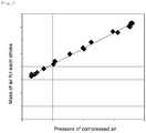
FIG. 2 shows correlation data between the mass of air for each stroke of the cylinders of the engine and the pressure of air to be supplied to an engine by a turbocharger, which is acquired through experiments; and -
FIG. 3 is a flowchart showing a reducing agent supply control method according to an embodiment of the present invention. - Embodiments of the present invention will be described in detail below with reference to the accompanying drawings so that those having ordinary knowledge in the art to which the present invention pertains can easily practice the present invention. The present invention may be implemented in various different forms, and is not limited to the embodiments described herein.
- It is noted that the drawings are schematic, and are not necessarily drawn to scale. The relative dimensions and ratios of the components in the drawings may be exaggerated or diminished in size for the sake of clarity and convenience, and such arbitrary dimensions are merely illustrative and are not limitative. Furthermore, the same reference symbol is used for the same structure, element or part shown in two or more drawings in order to represent similar features.
- The embodiments of the present invention specifically illustrate ideal embodiments of the present invention. As a result, various modifications of illustrations are expected. Accordingly, the embodiments are not limited to the specific forms of illustrated regions, and include, for example, the modifications of shapes resulting from manufacture.
- A
power apparatus 101 including a reducing agent supply control system according to an embodiment of the present invention will be described below with reference toFIG. 1 . - As shown in
FIG. 1 , thepower apparatus 101 including a reducing agent supply control system according to the embodiment of the present invention includes anengine 200, anexhaust passage 610, aturbocharger 300, apressure sensor 710, a nitrogenoxide concentration sensor 720, a reducingagent supply unit 400, and acontrol unit 700. - Furthermore, the
power apparatus 101 including a reducing agent supply control system according to the embodiment of the present invention may further include anintercooler 280, a selectivecatalytic reduction reactor 500, and atemperature sensor 760. - The
engine 200 includes one or more cylinders in which explosion strokes occur. Theengine 200 generates power by burning air and fuel at a preset air-fuel ratio. In this case, the air-fuel ratio may be preset by a manufacturer for each rotation speed and each load according to the type ofengine 200. - Furthermore, in an embodiment of the present invention, the
engine 200 emits exhaust gas containing a material under environmental regulations, such as nitrogen oxide NOx, or the like. - As an example, the
engine 200 may be a diesel engine, and may be used as a main power source for a ship. Furthermore, theengine 200 may be a four-stroke engine or two-stroke engine. - The
exhaust passage 610 emits the exhaust gas of theengine 200. In other words, the exhaust gas emitted by theengine 200 moves along theexhaust passage 610. - The
turbocharger 300 is connected to the cylinders of theengine 200, and pushes combustion air into the cylinders of theengine 200. - More specifically, the
turbocharger 300 is installed on theexhaust passage 610, and includes aturbine 310 configured to be rotated by pressure which the exhaust gas has and acompressor 320 configured to push air into theengine 200 by means of the rotating power of theturbine 310. - As described above, the
turbocharger 300 compresses new external air and supplies the compressed air to theengine body 200 by rotating theturbine 310 by means of pressure which the exhaust gas emitted by theengine body 200 has, thereby improving the output of theengine body 200. - The
intercooler 280 cools the intake air of theengine 200. - More specifically, the
intercooler 280 is disposed between theturbocharger 300 and theengine 200, and cools the air compressed by theturbocharger 300. The density of air compressed by theturbocharger 300 with effort becomes low due to heat which is generated when theturbocharger 300 compresses air. For this reason, charging efficiency is degraded in summer or the like when temperature is high. Theintercooler 280 increases the density of air, compressed by theturbocharger 300, by cooling the air. - The
pressure sensor 710 actually measures the pressure of air which is supplied to theengine 200 by theturbocharger 300. - In an embodiment of the present invention, the
pressure sensor 710 may be installed adjacent to the back end of theintercooler 280. In other words, thepressure sensor 710 may measure the pressure of air which is compressed in theturbocharger 300 and which is then cooled while passing through theintercooler 280. - The nitrogen oxide (NOx)
concentration sensor 720 may be installed on theexhaust passage 610, and may measure the concentration of the nitrogen oxide NOx of the exhaust gas emitted from theengine 200. - The selective
catalytic reduction reactor 500 is installed on theexhaust passage 610. The selectivecatalytic reduction reactor 500 includes a catalyst adapted to reduce nitrogen oxide NOx contained in the exhaust gas emitted from theengine 200. - The catalyst nitrogen reduces oxide NOx, contained in the exhaust gas, into nitrogen and water vapor by accelerating a reaction between nitrogen oxide NOx and a reducing agent. In this case, urea may be used as the reducing agent, and urea is decomposed into ammonia NH3 and reacts with nitrogen oxide NOx.
- The catalyst may be made of various materials, such as zeolite, vanadium, platinum, etc., which are well known to persons who participate in the corresponding technology field. As an example, the catalyst may have an activation temperature within the range from 250 to 450°C. In this case, the activation temperature refers to a temperature which enables nitrogen oxide to be stably reduced without poisoning the catalyst. When the catalyst reacts outside the activation temperature range, the catalyst is poisoned, and thus efficiency is degraded.
- More specifically, a poisoning material which poisons the catalyst may include one or more of ammonium sulfate (NH4)2SO4 and ammonium bisulfate NH4HSO4. Such a catalyst poisoning material is absorbed into the catalyst, and reduces the activity of the catalyst. Such a catalyst poisoning material is decomposed at a high temperature, and thus the poisoned catalyst may be recycled by heating the catalyst.
- The
temperature sensor 760 measures the internal temperature of the selectivecatalytic reduction reactor 500. More specifically, thetemperature sensor 760 is used to measure the temperature of the catalyst installed inside the selectivecatalytic reduction reactor 500. - The reducing
agent supply unit 400 supplies the reducing agent to the exhaust gas which moves along theexhaust passage 610. Furthermore, the reducingagent supply unit 400 may include a reducingagent storage unit 450 and a reducingagent injection unit 410. - The reducing
agent storage unit 450 stores a urea solution in which urea and water are mixed together, and supplies the urea solution into the reducingagent injection unit 410. In other words, the reducingagent injection unit 410 may inject the urea solution in which urea and water are mixed together. - Furthermore, the reducing
agent injection unit 410 injects the reducing agent into theexhaust passage 610 between theengine body 200 and thereactor 500. Accordingly, the exhaust gas is mixed with the reducing agent, and the mixture flows into thereactor 500. - When the urea solution is injected from the reducing
agent injection unit 410, urea of the urea solution is decomposed due to thermal energy which the exhaust gas has, and thus ammonia NH3 and isocyanic acid HNCO are generated and isocyanic acid HNCO, in turn, is decomposed into ammonia NH3 and carbon dioxide CO2. - In other words, the urea solution is finally decomposed into ammonia, and reacts with nitrogen oxide contained in the exhaust gas.
- The
control unit 700 determines the amount of reducing agent to be supplied based on information received from thepressure sensor 710 and the nitrogenoxide concentration sensor 720, and performs control so that the reducingagent supply unit 400 supplies the corresponding amount of reducing agent. In this case, thecontrol unit 700 may be the electronic control unit (ECU) of theengine 200, or may be a separate control device. - In an embodiment of the present invention, the
control unit 700 estimates the mass of air for each stroke by substituting the pressure of the air, actually measured by thepressure sensor 710, into correlation data between the masses and pressures of air which is supplied from theengine 200, as shown inFIG. 2 . - In this case, the mass of air may be the mass of air for each stroke of the cylinders of the
engine 200, and the pressure of air may be the pressure of air to be supplied to theengine 200. In an engine to which theturbocharger 300 is applied, the pressure of air compressed by theturbocharger 300 may be measured by measuring pressure downstream of theturbocharger 300. The correlations between the masses and pressures of air may be acquired through experiments, and may be stored in thecontrol unit 700. Furthermore, in the present specification, the "downstream" refers to backward based on a direction in which a fluid flows. - As an example, the correlation data between the masses of air for each stroke of the cylinders of the
engine 200 and the pressures of air to be supplied to theengine 200 by theturbocharger 300 may be acquired through experiments using a dynamometer. - In this case, in the case of the
diesel engine 200 equipped with theturbocharger 300, a result in which the masses of air for each cylinder stroke and boost pressures in back of thestroke compressor 320 of theturbocharger 300 exhibit the linear relationship of a linear expression can be acquired through a great deal of effort and investment. - Furthermore, the
control unit 700 calculates the mass of air per hour by using the mass of air for each stroke which is estimated by considering the rotation speed of theengine 200 and the total number of cylinders of theengine 200. - In this case, the
control unit 700 may calculate the mass of air per hour by using the following equation:
- Thereafter, the
control unit 700 calculates the mass of fuel per hour by dividing the mass of air per hour by air-fuel ratio. In this case, the air-fuel ratio is preset by a manufacturer according to the type ofengine 200. - The
control unit 700 may calculate the total amount of nitrogen oxide, emitted from theengine 200, by using nitrogen oxide (NOx) concentration measured by the nitrogenoxide concentration sensor 720, the mass of air per hour, and the mass of fuel per hour. When the total amount of nitrogen oxide is calculated, thecontrol unit 700 determines the amount of reducing agent to be supplied, which can reduce nitrogen oxide, and controls the reducingagent supply unit 400 so that the corresponding amount of reducing agent is supplied. - Furthermore, in an embodiment of the present invention, the
control unit 700 may correct the calculated amount of reducing agent to be injected by considering the rotation speed and load of theengine 200 and the reduction rate of the reducing agent. - The amount of reducing agent to be supplied at the above-described step is a value which is calculated when an ammonia-to-NOx ratio is in a theoretical state (where ANR [Ammonia to NOx Ratio]=1).
- However, in the selective catalytic reduction reaction adapted to reduce nitrogen oxide, efficiency may be reduced due to the degree of degradation of the catalyst, the reaction activation temperature of the catalyst, or the like.
- Accordingly, it is necessary to supply an amount of reducing agent larger than the above-described theoretically calculated amount of reducing agent to be supplied.
- Accordingly, in an embodiment of the present invention, a table may be constructed and used by determining the efficiency of the selective catalytic reduction reaction in the catalyst for each rotation speed and load of the
engine 200 through experiments and mapping a reducing agent injection amount correction value for each rotation speed and load of theengine 200 in order to control the actual appropriate amount of reducing agent to be injected for each theoretical value. - By correcting the amount of reducing agent to be supplied by means of the above-described table, the ammonia-to-NOx ratio (ANR) may be set to a higher value in a load interval of the
engine 200 in which it is desired to increase selective catalytic reduction reaction efficiency, and then mapping may be performed. - In contrast, in an interval in which a large amount of ammonia slip occurs, the ammonia-to-NOx ratio (ANR) may be set to a lower value, and then mapping may be performed, thereby minimizing the amount of ammonia slip.
- Furthermore, in an embodiment of the present invention, the
control unit 700 may correct the calculated amount of reducing agent to be supplied according to the temperature of the catalyst. - The catalyst which is used in the selective catalytic reduction reaction has a low-efficiency temperature interval and a high-efficiency temperature interval depending on the type and components thereof.
- When the temperature of the catalyst falls within the low-efficiency temperature interval, only urea is consumed without a nitrogen oxide (NOx) reduction effect. Furthermore, a urea crystallization phenomenon may occur when urea is injected.
- Accordingly, when the temperature of the catalyst falls within the low-efficiency temperature interval, the amount of reducing agent to be supplied may be corrected such that the amount of reducing agent to be supplied is reduced or restricted.
- Furthermore, when the temperature of the catalyst falls within the high-efficiency temperature interval, nitrogen oxide removal efficiency may be maximized by increasing the amount of reducing agent to be supplied.
- The activation temperature of the catalyst varies depending on the type and components of the catalyst. As an example, the catalyst may exhibit significantly low efficiency at a temperature below 200°C, and may exhibit significantly high efficiency in the range from 350 to 450°C.
- By using the above-described configuration, the
power apparatus 101 including a reducing agent supply control system according to the embodiment of the present invention can effectively control the supply of the reducing agent which is used in a reduction reaction of nitrogen oxide. - A reducing agent supply control method according to an embodiment of the present invention will be described with reference to
FIG. 3 . - The reducing agent supply control method according to the embodiment of the present invention is a method for supplying a reducing agent required to reduce nitrogen oxide NOx contained in exhaust gas which is emitted from the
engine 200 after theengine 200 has received air compressed by theturbocharger 300 and has burned the air, together with fuel, at the preset air-fuel ratio. - First, the pressure of air to be supplied to the
engine 200 is actually measured. When theturbocharger 300 is applied, the actually measured pressure of air may be the pressure of air which is compressed by theturbocharger 300 and then supplied to theengine 200. - The mass of air is estimated by comparing the pressure of air actually measured as described above with previously stored correlation data between the masses and pressures of air. The mass of air may be the mass of air for each stroke of the cylinders of the
engine 200. This correlation data may be acquired through previously conducted experiments, and may be stored in thecontrol unit 700. - As an example, the correlation data between the masses of air for each stroke of the cylinders of the
engine 200 and the pressures of air to be supplied to theengine 200 by theturbocharger 300 may be acquired through experiments using a dynamometer, and the correlation data may be prepared in the form of a graph. - Thereafter, the mass of air per hour is calculated using the mass of air for each stroke which is estimated by considering the rotation speed of the
engine 200 and the total number of cylinders of theengine 200. - In this case, the mass of air per hour may be calculated using the following equation:

- Thereafter, the mass of fuel per hour is calculated by dividing the mass of air per hour by air-fuel ratio. A value preset by a manufacturer according to the type of
engine 200 is provided as the air-fuel ratio. - Thereafter, the nitrogen oxide (NOx) concentration of the exhaust gas emitted from the
engine 200 is measured. Furthermore, the total amount of nitrogen oxide emitted from theengine 200 is calculated using the mass of air per hour, the mass of fuel per hour, and the nitrogen oxide concentration. - When the total amount of nitrogen oxide is calculated, the amount of reducing agent to be supplied, which can reduce nitrogen oxide, is calculated.
- Thereafter, the reducing agent is supplied according to the calculated value.
- Furthermore, in the reducing agent supply control method according to the embodiment of the present invention, the amount of reducing agent to be supplied, which is calculated by considering the rotation speed and load of the
engine 200 and the reduction rate of the reducing agent, may be corrected. - In the selective catalytic reduction reaction adapted to reduce nitrogen oxide, efficiency may be reduced due to the degree of degradation of the catalyst, the reaction activation temperature of the catalyst, etc., and thus it is necessary to supply an amount of reducing agent larger than the above-described theoretically calculated amount of reducing agent to be supplied.
- Accordingly, in an embodiment of the present invention, a table may be constructed and used by determining the efficiency of the selective catalytic reduction reaction in the catalyst for each rotation speed and load of the
engine 200 through experiments and mapping a reducing agent injection amount correction value for each rotation speed and load of theengine 200 in order to control the actual appropriate amount of reducing agent to be injected for each theoretical value. - Furthermore, in the reducing agent supply control method according to the embodiment of the present invention, a reduction reaction adapted to convert nitrogen oxide may be accelerated using a catalyst. Furthermore, the calculated amount of reducing agent to be supplied may be corrected according to the temperature of the catalyst.
- The catalyst which is used in the selective catalytic reduction reaction has a low-efficiency temperature interval and a high-temperature interval depending on the type and components thereof.
- Accordingly, by correcting the amount of reducing agent to be supplied according to the temperature of the catalyst, the reducing agent may be prevented from being unnecessarily wasted, and also an ammonia slip phenomenon may be prevented from occurring.
- As described above, the reducing agent supply control method according to the embodiment of the present invention can effectively control the supply of the reducing agent which is used in a reduction reaction of nitrogen oxide.
- Although the embodiments of the present invention have been described with reference to the accompanying drawings, it will be understood by those skilled in the art to which the present invention pertains that the present invention may be practiced in other specific forms without a change to the technical spirit and essential features thereof.
- Therefore, it should be understood that the above-described embodiments are illustrative but are not limitative in all aspects, the scope of the present invention is defined by the following claims rather than the detailed description, and all modifications and variations derived from the meanings and ranges of the claims and concepts equivalent to the claims should be construed as falling within the scope of the present invention.
- The power apparatus including a reducing agent supply control system and the reducing agent supply method according to the embodiments of the present invention may be used to effectively control the supply of a reducing agent which is used in a reduction reaction of nitrogen oxide.
Claims (12)
- A power apparatus including a reducing agent supply control system, the power apparatus comprising:an engine configured to emit exhaust gas containing nitrogen oxide by burning air and fuel at a preset air-fuel ratio;an exhaust passage configured such that the exhaust gas emitted by the engine moves therethrough;a pressure sensor configured to actually measure a pressure of air which is supplied to the engine;a nitrogen oxide concentration sensor installed on the exhaust passage, and configured to measure a nitrogen oxide (NOx) concentration of the exhaust gas;a reducing agent supply unit configured to supply a reducing agent to the exhaust gas which moves along the exhaust passage; anda control unit configured to determine an amount of reducing agent to be supplied based on information received from the pressure sensor and the nitrogen oxide concentration sensor, and to control the reducing agent supply unit.
- The power apparatus of claim 1, wherein the control unit:calculates a mass of air for each stroke of one or more cylinders of the engine from the pressure of air, actually measured by the pressure sensor, by using preset correlation data between a pressure and mass of air to be supplied to the engine;calculates a mass of air per hour by using a rotation speed of the engine, a total number of cylinders of the engine, and the calculated mass of air for each stroke;calculates a mass of fuel per hour by dividing the mass of air per hour by an air-fuel ratio; andcalculates a total amount of nitrogen oxide emitted from the engine by using the nitrogen oxide (NOx) concentration measured by the nitrogen oxide concentration sensor, the mass of air per hour, and the mass of fuel per hour, and determines an amount of reducing agent to be supplied, which reduces the total amount of nitrogen oxide.
- The power apparatus of claim 2, wherein the correlation data is set by acquiring correlations between masses of air for each stroke of the cylinders of the engine and pressures of air to be supplied to the engine through experiments.
- The power apparatus of claim 2, wherein the control unit calculates the mass of air per hour by using the following equation:

- The power apparatus of claim 1, further comprising:a turbocharger including a turbine configured to be rotated by a pressure which the exhaust gas has and a compressor configured to receive power from the turbine and to compress the air to be supplied to the engine, and installed on the exhaust passage; andan intercooler installed on a path between the compressor of the turbocharger and the engine;wherein the pressure sensor is installed downstream of the intercooler, and measures the pressure of air which is compressed by the turbocharger and is then supplied to the engine.
- The power apparatus of claim 2, wherein the control unit corrects the calculated amount of reducing agent to be injected by considering a rotation speed and load of the engine and a reduction rate of the reducing agent.
- The power apparatus of claim 2, further comprising:a selective catalytic reduction reactor installed on the exhaust passage, and including a catalyst configured to accelerate a reaction between nitrogen oxide contained in the exhaust gas and the reducing agent supplied by the reducing agent supply unit; anda temperature sensor configured to measure an internal temperature of the selective catalytic reduction reactor;wherein the control unit corrects the calculated amount of reducing agent to be supplied according to a temperature of the catalyst.
- A reducing agent supply control method for reducing nitrogen oxide (NOx) contained in exhaust gas emitted by an engine after the engine has received air and has burned the air, together with fuel, at a preset air-fuel ratio, the reducing agent supply control method comprising:actually measuring a pressure of air to be supplied to the engine, and calculating a mass of air for each stroke of one or more cylinders of the engine by using preset correlation data;calculating a mass of air per hour by using the mass of air for each stroke which is estimated by considering a rotation speed of the engine and a number of cylinders of the engine;calculating a mass of fuel per hour by dividing the mass of air per hour by an air-fuel ratio;measuring a nitrogen oxide (NOx) concentration of the exhaust gas emitted from the engine;calculating a total amount of nitrogen oxide emitted from the engine by using the mass of air per hour, the mass of fuel per hour, and the nitrogen oxide concentration; andcalculating an amount of reducing agent to be supplied, which reduces the total amount of nitrogen oxide.
- The reducing agent supply control method of claim 8,
wherein the correlation data is related to correlations between masses of air for each stroke of the cylinders of the engine and pressures of air to be supplied to the engine, which are acquired through experiments. - The reducing agent supply control method of claim 8,
wherein the mass of air per hour is calculated using the following equation:
- The reducing agent supply control method of claim 8, further comprising correcting the calculated amount of reducing agent to be supplied by considering a rotation speed and load of the engine and a reduction rate of the reducing agent.
- The reducing agent supply control method of claim 8, further comprising:accelerating a reduction reaction adapted to convert nitrogen oxide by using a catalyst; andcorrecting the calculated amount of reducing agent to be supplied according to a temperature of the catalyst.
Applications Claiming Priority (2)
| Application Number | Priority Date | Filing Date | Title |
|---|---|---|---|
| KR1020150056125A KR102301917B1 (en) | 2015-04-21 | 2015-04-21 | Power plant with reductant supply control system and method for control reductant supply |
| PCT/KR2016/004142 WO2016171481A1 (en) | 2015-04-21 | 2016-04-21 | Power apparatus including reducing agent supply control system and reducing agent supply control method |
Publications (3)
| Publication Number | Publication Date |
|---|---|
| EP3287617A1 true EP3287617A1 (en) | 2018-02-28 |
| EP3287617A4 EP3287617A4 (en) | 2018-10-03 |
| EP3287617B1 EP3287617B1 (en) | 2020-08-12 |
Family
ID=57144050
Family Applications (1)
| Application Number | Title | Priority Date | Filing Date |
|---|---|---|---|
| EP16783414.2A Not-in-force EP3287617B1 (en) | 2015-04-21 | 2016-04-21 | Power apparatus including reducing agent supply control system and reducing agent supply control method |
Country Status (5)
| Country | Link |
|---|---|
| US (1) | US10408107B2 (en) |
| EP (1) | EP3287617B1 (en) |
| KR (1) | KR102301917B1 (en) |
| CN (1) | CN107532493B (en) |
| WO (1) | WO2016171481A1 (en) |
Families Citing this family (5)
| Publication number | Priority date | Publication date | Assignee | Title |
|---|---|---|---|---|
| CN109580876B (en) * | 2018-10-24 | 2021-03-19 | 中交疏浚技术装备国家工程研究中心有限公司 | System and method for measuring mixing amount of pipeline slurry curing agent |
| CN111219235A (en) * | 2018-11-23 | 2020-06-02 | 宝沃汽车(中国)有限公司 | Vehicle exhaust gas treatment method, device, storage medium and vehicle |
| KR102483964B1 (en) * | 2021-03-09 | 2023-01-04 | 정진도 | NOx REDUCTION FACILITY CONTROL METHOD OF GAS TURBINE COMBINED CYCLE POWER PLANT USING NATURAL GAS |
| KR102431125B1 (en) * | 2021-10-14 | 2022-08-11 | 박정봉 | NOx reduction system and control method thereof |
| DK182158B1 (en) * | 2024-03-13 | 2025-09-24 | Everllence Filial Af Everllence Se Tyskland | A LARGE TWO-STROKE UNIFLOW SCAVENGED TURBOCHARGED INTERNAL COMBUSTION ENGINE WITH AN SCR REACTOR FOR REDUCING NOx EMISSIONS AND METHOD FOR CONTROLLING NOx REDUCTION IN SUCH ENGINE |
Family Cites Families (11)
| Publication number | Priority date | Publication date | Assignee | Title |
|---|---|---|---|---|
| DE4315278A1 (en) * | 1993-05-07 | 1994-11-10 | Siemens Ag | Method and device for metering a reducing agent into a nitrogen-containing exhaust gas |
| DE19903439A1 (en) * | 1999-01-29 | 2000-08-03 | Bosch Gmbh Robert | Method and device for controlling an exhaust gas aftertreatment system |
| KR100441481B1 (en) * | 2000-07-24 | 2004-07-23 | 도요타지도샤가부시키가이샤 | Exhaust gas purification device for internal combustion engine |
| DE10100419A1 (en) | 2001-01-08 | 2002-07-11 | Bosch Gmbh Robert | Method and device for controlling an exhaust gas aftertreatment system |
| DE602005001922T2 (en) * | 2004-12-18 | 2007-12-06 | Haldor Topsoe A/S | Method for controlling the addition of a reducing agent in the exhaust gas of an internal combustion engine |
| US9068489B2 (en) * | 2011-03-28 | 2015-06-30 | Haldor Topsoe A/S | Process for the reduction of nitrogen oxides and sulphur oxides in the exhaust gas from internal combustion engine |
| JP5269174B2 (en) | 2011-11-28 | 2013-08-21 | 株式会社豊田自動織機 | Exhaust gas purification device in internal combustion engine |
| JP5908814B2 (en) * | 2012-09-13 | 2016-04-26 | 株式会社小松製作所 | Exhaust gas treatment device, diesel engine and exhaust gas treatment method |
| KR101497833B1 (en) * | 2013-10-11 | 2015-03-02 | 두산엔진주식회사 | Selective catalytic reduction system |
| KR101513804B1 (en) * | 2013-10-18 | 2015-04-20 | 두산엔진주식회사 | Power plant with selective catalytic reuction system and control method of selective catalytic reduction system |
| US20150308321A1 (en) * | 2014-04-25 | 2015-10-29 | Caterpillar Inc. | Exhaust emission prediction system and method |
-
2015
- 2015-04-21 KR KR1020150056125A patent/KR102301917B1/en active Active
-
2016
- 2016-04-21 CN CN201680022597.7A patent/CN107532493B/en not_active Expired - Fee Related
- 2016-04-21 US US15/568,606 patent/US10408107B2/en not_active Expired - Fee Related
- 2016-04-21 WO PCT/KR2016/004142 patent/WO2016171481A1/en not_active Ceased
- 2016-04-21 EP EP16783414.2A patent/EP3287617B1/en not_active Not-in-force
Also Published As
| Publication number | Publication date |
|---|---|
| US20180149057A1 (en) | 2018-05-31 |
| EP3287617B1 (en) | 2020-08-12 |
| WO2016171481A1 (en) | 2016-10-27 |
| US10408107B2 (en) | 2019-09-10 |
| CN107532493A (en) | 2018-01-02 |
| EP3287617A4 (en) | 2018-10-03 |
| KR102301917B1 (en) | 2021-09-14 |
| CN107532493B (en) | 2020-01-17 |
| KR20160125223A (en) | 2016-10-31 |
Similar Documents
| Publication | Publication Date | Title |
|---|---|---|
| US7892508B2 (en) | Internal combustion engine exhaust gas purification apparatus and method for controlling same | |
| US8041498B2 (en) | Lean nitrogen oxide emission control system and method | |
| AU2014271742B2 (en) | Abnormality diagnosis apparatus of exhaust gas purification apparatus | |
| US9133749B2 (en) | Ammonia storage set-point control for selective catalytic reduction applications | |
| US7707824B2 (en) | Excess NH3 storage control for SCR catalysts | |
| CN101578434B (en) | Catalyst Deterioration Determination Device | |
| US10408107B2 (en) | Power apparatus including reducing agent supply control system and reducing agent supply control method | |
| US8943804B2 (en) | Compression-ignition engine with exhaust system | |
| US8621854B2 (en) | System and method for determining an age of and controlling a selective catalytic reduction catalyst | |
| US8745973B2 (en) | System and method for controlling reducing agent injection in a selective catalytic reduction system | |
| US20080250774A1 (en) | Reductant injection control strategy | |
| US8652410B2 (en) | Control method and arrangement for selective catalytic reduction | |
| US20040098968A1 (en) | Exhaust gas aftertreatment systems | |
| CN102713180B (en) | For the method controlled the reducing agent buffer level in exhaust gas post-treatment device | |
| AU2014271738B2 (en) | Abnormality diagnosis apparatus of exhaust gas purification apparatus | |
| EP2295753B1 (en) | Method for urea injection control | |
| EP2940280B1 (en) | Fuel-cetane-number estimation method and apparatus | |
| CN103069121B (en) | Control equipment and the method for the reduction dosage introduced in I. C. engine exhaust pipeline | |
| CN113607398B (en) | Method for accurately measuring SCR ammonia injection ratio | |
| US20130160521A1 (en) | System and method of generating selective catalyst reduction dosing estimate for a diesel engine |
Legal Events
| Date | Code | Title | Description |
|---|---|---|---|
| STAA | Information on the status of an ep patent application or granted ep patent |
Free format text: STATUS: THE INTERNATIONAL PUBLICATION HAS BEEN MADE |
|
| PUAI | Public reference made under article 153(3) epc to a published international application that has entered the european phase |
Free format text: ORIGINAL CODE: 0009012 |
|
| STAA | Information on the status of an ep patent application or granted ep patent |
Free format text: STATUS: REQUEST FOR EXAMINATION WAS MADE |
|
| 17P | Request for examination filed |
Effective date: 20171113 |
|
| AK | Designated contracting states |
Kind code of ref document: A1 Designated state(s): AL AT BE BG CH CY CZ DE DK EE ES FI FR GB GR HR HU IE IS IT LI LT LU LV MC MK MT NL NO PL PT RO RS SE SI SK SM TR |
|
| AX | Request for extension of the european patent |
Extension state: BA ME |
|
| DAV | Request for validation of the european patent (deleted) | ||
| DAX | Request for extension of the european patent (deleted) | ||
| A4 | Supplementary search report drawn up and despatched |
Effective date: 20180830 |
|
| RIC1 | Information provided on ipc code assigned before grant |
Ipc: F01N 11/00 20060101ALI20180824BHEP Ipc: F01N 9/00 20060101ALI20180824BHEP Ipc: F01N 3/20 20060101AFI20180824BHEP Ipc: F02B 37/00 20060101ALI20180824BHEP |
|
| GRAP | Despatch of communication of intention to grant a patent |
Free format text: ORIGINAL CODE: EPIDOSNIGR1 |
|
| STAA | Information on the status of an ep patent application or granted ep patent |
Free format text: STATUS: GRANT OF PATENT IS INTENDED |
|
| INTG | Intention to grant announced |
Effective date: 20200317 |
|
| GRAS | Grant fee paid |
Free format text: ORIGINAL CODE: EPIDOSNIGR3 |
|
| GRAA | (expected) grant |
Free format text: ORIGINAL CODE: 0009210 |
|
| STAA | Information on the status of an ep patent application or granted ep patent |
Free format text: STATUS: THE PATENT HAS BEEN GRANTED |
|
| AK | Designated contracting states |
Kind code of ref document: B1 Designated state(s): AL AT BE BG CH CY CZ DE DK EE ES FI FR GB GR HR HU IE IS IT LI LT LU LV MC MK MT NL NO PL PT RO RS SE SI SK SM TR |
|
| REG | Reference to a national code |
Ref country code: CH Ref legal event code: EP |
|
| REG | Reference to a national code |
Ref country code: IE Ref legal event code: FG4D |
|
| REG | Reference to a national code |
Ref country code: DE Ref legal event code: R096 Ref document number: 602016041924 Country of ref document: DE |
|
| REG | Reference to a national code |
Ref country code: AT Ref legal event code: REF Ref document number: 1301765 Country of ref document: AT Kind code of ref document: T Effective date: 20200915 |
|
| REG | Reference to a national code |
Ref country code: LT Ref legal event code: MG4D |
|
| REG | Reference to a national code |
Ref country code: NL Ref legal event code: MP Effective date: 20200812 |
|
| PG25 | Lapsed in a contracting state [announced via postgrant information from national office to epo] |
Ref country code: SE Free format text: LAPSE BECAUSE OF FAILURE TO SUBMIT A TRANSLATION OF THE DESCRIPTION OR TO PAY THE FEE WITHIN THE PRESCRIBED TIME-LIMIT Effective date: 20200812 Ref country code: NO Free format text: LAPSE BECAUSE OF FAILURE TO SUBMIT A TRANSLATION OF THE DESCRIPTION OR TO PAY THE FEE WITHIN THE PRESCRIBED TIME-LIMIT Effective date: 20201112 Ref country code: GR Free format text: LAPSE BECAUSE OF FAILURE TO SUBMIT A TRANSLATION OF THE DESCRIPTION OR TO PAY THE FEE WITHIN THE PRESCRIBED TIME-LIMIT Effective date: 20201113 Ref country code: FI Free format text: LAPSE BECAUSE OF FAILURE TO SUBMIT A TRANSLATION OF THE DESCRIPTION OR TO PAY THE FEE WITHIN THE PRESCRIBED TIME-LIMIT Effective date: 20200812 Ref country code: BG Free format text: LAPSE BECAUSE OF FAILURE TO SUBMIT A TRANSLATION OF THE DESCRIPTION OR TO PAY THE FEE WITHIN THE PRESCRIBED TIME-LIMIT Effective date: 20201112 Ref country code: HR Free format text: LAPSE BECAUSE OF FAILURE TO SUBMIT A TRANSLATION OF THE DESCRIPTION OR TO PAY THE FEE WITHIN THE PRESCRIBED TIME-LIMIT Effective date: 20200812 Ref country code: LT Free format text: LAPSE BECAUSE OF FAILURE TO SUBMIT A TRANSLATION OF THE DESCRIPTION OR TO PAY THE FEE WITHIN THE PRESCRIBED TIME-LIMIT Effective date: 20200812 |
|
| REG | Reference to a national code |
Ref country code: AT Ref legal event code: MK05 Ref document number: 1301765 Country of ref document: AT Kind code of ref document: T Effective date: 20200812 |
|
| PG25 | Lapsed in a contracting state [announced via postgrant information from national office to epo] |
Ref country code: NL Free format text: LAPSE BECAUSE OF FAILURE TO SUBMIT A TRANSLATION OF THE DESCRIPTION OR TO PAY THE FEE WITHIN THE PRESCRIBED TIME-LIMIT Effective date: 20200812 Ref country code: LV Free format text: LAPSE BECAUSE OF FAILURE TO SUBMIT A TRANSLATION OF THE DESCRIPTION OR TO PAY THE FEE WITHIN THE PRESCRIBED TIME-LIMIT Effective date: 20200812 Ref country code: PL Free format text: LAPSE BECAUSE OF FAILURE TO SUBMIT A TRANSLATION OF THE DESCRIPTION OR TO PAY THE FEE WITHIN THE PRESCRIBED TIME-LIMIT Effective date: 20200812 Ref country code: RS Free format text: LAPSE BECAUSE OF FAILURE TO SUBMIT A TRANSLATION OF THE DESCRIPTION OR TO PAY THE FEE WITHIN THE PRESCRIBED TIME-LIMIT Effective date: 20200812 Ref country code: IS Free format text: LAPSE BECAUSE OF FAILURE TO SUBMIT A TRANSLATION OF THE DESCRIPTION OR TO PAY THE FEE WITHIN THE PRESCRIBED TIME-LIMIT Effective date: 20201212 |
|
| PG25 | Lapsed in a contracting state [announced via postgrant information from national office to epo] |
Ref country code: SM Free format text: LAPSE BECAUSE OF FAILURE TO SUBMIT A TRANSLATION OF THE DESCRIPTION OR TO PAY THE FEE WITHIN THE PRESCRIBED TIME-LIMIT Effective date: 20200812 Ref country code: EE Free format text: LAPSE BECAUSE OF FAILURE TO SUBMIT A TRANSLATION OF THE DESCRIPTION OR TO PAY THE FEE WITHIN THE PRESCRIBED TIME-LIMIT Effective date: 20200812 Ref country code: DK Free format text: LAPSE BECAUSE OF FAILURE TO SUBMIT A TRANSLATION OF THE DESCRIPTION OR TO PAY THE FEE WITHIN THE PRESCRIBED TIME-LIMIT Effective date: 20200812 Ref country code: CZ Free format text: LAPSE BECAUSE OF FAILURE TO SUBMIT A TRANSLATION OF THE DESCRIPTION OR TO PAY THE FEE WITHIN THE PRESCRIBED TIME-LIMIT Effective date: 20200812 Ref country code: RO Free format text: LAPSE BECAUSE OF FAILURE TO SUBMIT A TRANSLATION OF THE DESCRIPTION OR TO PAY THE FEE WITHIN THE PRESCRIBED TIME-LIMIT Effective date: 20200812 |
|
| REG | Reference to a national code |
Ref country code: DE Ref legal event code: R097 Ref document number: 602016041924 Country of ref document: DE |
|
| PG25 | Lapsed in a contracting state [announced via postgrant information from national office to epo] |
Ref country code: ES Free format text: LAPSE BECAUSE OF FAILURE TO SUBMIT A TRANSLATION OF THE DESCRIPTION OR TO PAY THE FEE WITHIN THE PRESCRIBED TIME-LIMIT Effective date: 20200812 Ref country code: AT Free format text: LAPSE BECAUSE OF FAILURE TO SUBMIT A TRANSLATION OF THE DESCRIPTION OR TO PAY THE FEE WITHIN THE PRESCRIBED TIME-LIMIT Effective date: 20200812 Ref country code: AL Free format text: LAPSE BECAUSE OF FAILURE TO SUBMIT A TRANSLATION OF THE DESCRIPTION OR TO PAY THE FEE WITHIN THE PRESCRIBED TIME-LIMIT Effective date: 20200812 |
|
| PLBE | No opposition filed within time limit |
Free format text: ORIGINAL CODE: 0009261 |
|
| STAA | Information on the status of an ep patent application or granted ep patent |
Free format text: STATUS: NO OPPOSITION FILED WITHIN TIME LIMIT |
|
| PG25 | Lapsed in a contracting state [announced via postgrant information from national office to epo] |
Ref country code: SK Free format text: LAPSE BECAUSE OF FAILURE TO SUBMIT A TRANSLATION OF THE DESCRIPTION OR TO PAY THE FEE WITHIN THE PRESCRIBED TIME-LIMIT Effective date: 20200812 |
|
| 26N | No opposition filed |
Effective date: 20210514 |
|
| PG25 | Lapsed in a contracting state [announced via postgrant information from national office to epo] |
Ref country code: IT Free format text: LAPSE BECAUSE OF FAILURE TO SUBMIT A TRANSLATION OF THE DESCRIPTION OR TO PAY THE FEE WITHIN THE PRESCRIBED TIME-LIMIT Effective date: 20200812 |
|
| PG25 | Lapsed in a contracting state [announced via postgrant information from national office to epo] |
Ref country code: SI Free format text: LAPSE BECAUSE OF FAILURE TO SUBMIT A TRANSLATION OF THE DESCRIPTION OR TO PAY THE FEE WITHIN THE PRESCRIBED TIME-LIMIT Effective date: 20200812 |
|
| REG | Reference to a national code |
Ref country code: DE Ref legal event code: R081 Ref document number: 602016041924 Country of ref document: DE Owner name: HYUNDAI DOOSAN INFRACORE CO., LTD., KR Free format text: FORMER OWNER: DOOSAN INFRACORE CO., LTD., INCHEON, KR |
|
| PG25 | Lapsed in a contracting state [announced via postgrant information from national office to epo] |
Ref country code: MC Free format text: LAPSE BECAUSE OF FAILURE TO SUBMIT A TRANSLATION OF THE DESCRIPTION OR TO PAY THE FEE WITHIN THE PRESCRIBED TIME-LIMIT Effective date: 20200812 |
|
| GBPC | Gb: european patent ceased through non-payment of renewal fee |
Effective date: 20210421 |
|
| PG25 | Lapsed in a contracting state [announced via postgrant information from national office to epo] |
Ref country code: LU Free format text: LAPSE BECAUSE OF NON-PAYMENT OF DUE FEES Effective date: 20210421 |
|
| REG | Reference to a national code |
Ref country code: BE Ref legal event code: MM Effective date: 20210430 |
|
| PG25 | Lapsed in a contracting state [announced via postgrant information from national office to epo] |
Ref country code: FR Free format text: LAPSE BECAUSE OF NON-PAYMENT OF DUE FEES Effective date: 20210430 Ref country code: GB Free format text: LAPSE BECAUSE OF NON-PAYMENT OF DUE FEES Effective date: 20210421 Ref country code: LI Free format text: LAPSE BECAUSE OF NON-PAYMENT OF DUE FEES Effective date: 20210430 Ref country code: CH Free format text: LAPSE BECAUSE OF NON-PAYMENT OF DUE FEES Effective date: 20210430 |
|
| PG25 | Lapsed in a contracting state [announced via postgrant information from national office to epo] |
Ref country code: IE Free format text: LAPSE BECAUSE OF NON-PAYMENT OF DUE FEES Effective date: 20210421 |
|
| PG25 | Lapsed in a contracting state [announced via postgrant information from national office to epo] |
Ref country code: IS Free format text: LAPSE BECAUSE OF FAILURE TO SUBMIT A TRANSLATION OF THE DESCRIPTION OR TO PAY THE FEE WITHIN THE PRESCRIBED TIME-LIMIT Effective date: 20201212 |
|
| PG25 | Lapsed in a contracting state [announced via postgrant information from national office to epo] |
Ref country code: BE Free format text: LAPSE BECAUSE OF NON-PAYMENT OF DUE FEES Effective date: 20210430 |
|
| PGFP | Annual fee paid to national office [announced via postgrant information from national office to epo] |
Ref country code: DE Payment date: 20220223 Year of fee payment: 7 |
|
| PG25 | Lapsed in a contracting state [announced via postgrant information from national office to epo] |
Ref country code: PT Free format text: LAPSE BECAUSE OF FAILURE TO SUBMIT A TRANSLATION OF THE DESCRIPTION OR TO PAY THE FEE WITHIN THE PRESCRIBED TIME-LIMIT Effective date: 20201214 |
|
| PG25 | Lapsed in a contracting state [announced via postgrant information from national office to epo] |
Ref country code: HU Free format text: LAPSE BECAUSE OF FAILURE TO SUBMIT A TRANSLATION OF THE DESCRIPTION OR TO PAY THE FEE WITHIN THE PRESCRIBED TIME-LIMIT; INVALID AB INITIO Effective date: 20160421 |
|
| PG25 | Lapsed in a contracting state [announced via postgrant information from national office to epo] |
Ref country code: CY Free format text: LAPSE BECAUSE OF FAILURE TO SUBMIT A TRANSLATION OF THE DESCRIPTION OR TO PAY THE FEE WITHIN THE PRESCRIBED TIME-LIMIT Effective date: 20200812 |
|
| REG | Reference to a national code |
Ref country code: DE Ref legal event code: R119 Ref document number: 602016041924 Country of ref document: DE |
|
| PG25 | Lapsed in a contracting state [announced via postgrant information from national office to epo] |
Ref country code: DE Free format text: LAPSE BECAUSE OF NON-PAYMENT OF DUE FEES Effective date: 20231103 |
|
| PG25 | Lapsed in a contracting state [announced via postgrant information from national office to epo] |
Ref country code: MK Free format text: LAPSE BECAUSE OF FAILURE TO SUBMIT A TRANSLATION OF THE DESCRIPTION OR TO PAY THE FEE WITHIN THE PRESCRIBED TIME-LIMIT Effective date: 20200812 |
|
| PG25 | Lapsed in a contracting state [announced via postgrant information from national office to epo] |
Ref country code: MT Free format text: LAPSE BECAUSE OF FAILURE TO SUBMIT A TRANSLATION OF THE DESCRIPTION OR TO PAY THE FEE WITHIN THE PRESCRIBED TIME-LIMIT Effective date: 20200812 |
|
| PG25 | Lapsed in a contracting state [announced via postgrant information from national office to epo] |
Ref country code: TR Free format text: LAPSE BECAUSE OF FAILURE TO SUBMIT A TRANSLATION OF THE DESCRIPTION OR TO PAY THE FEE WITHIN THE PRESCRIBED TIME-LIMIT Effective date: 20200812 |