EP3287607A1 - Vane actuator and method of making and using the same - Google Patents
Vane actuator and method of making and using the same Download PDFInfo
- Publication number
- EP3287607A1 EP3287607A1 EP17173799.2A EP17173799A EP3287607A1 EP 3287607 A1 EP3287607 A1 EP 3287607A1 EP 17173799 A EP17173799 A EP 17173799A EP 3287607 A1 EP3287607 A1 EP 3287607A1
- Authority
- EP
- European Patent Office
- Prior art keywords
- vane
- variations
- ring
- actuator
- vanes
- Prior art date
- Legal status (The legal status is an assumption and is not a legal conclusion. Google has not performed a legal analysis and makes no representation as to the accuracy of the status listed.)
- Granted
Links
- 238000004519 manufacturing process Methods 0.000 title description 2
- 230000008878 coupling Effects 0.000 claims abstract description 9
- 238000010168 coupling process Methods 0.000 claims abstract description 9
- 238000005859 coupling reaction Methods 0.000 claims abstract description 9
- 238000000034 method Methods 0.000 claims description 23
- 239000012530 fluid Substances 0.000 description 4
- 125000006850 spacer group Chemical group 0.000 description 3
- 238000005461 lubrication Methods 0.000 description 2
- 229920000049 Carbon (fiber) Polymers 0.000 description 1
- 229910001018 Cast iron Inorganic materials 0.000 description 1
- 229910052782 aluminium Inorganic materials 0.000 description 1
- XAGFODPZIPBFFR-UHFFFAOYSA-N aluminium Chemical compound [Al] XAGFODPZIPBFFR-UHFFFAOYSA-N 0.000 description 1
- 239000004917 carbon fiber Substances 0.000 description 1
- 238000005266 casting Methods 0.000 description 1
- 150000001875 compounds Chemical class 0.000 description 1
- 239000002826 coolant Substances 0.000 description 1
- 230000009977 dual effect Effects 0.000 description 1
- 238000003754 machining Methods 0.000 description 1
- 239000000463 material Substances 0.000 description 1
- 229910052751 metal Inorganic materials 0.000 description 1
- 239000002184 metal Substances 0.000 description 1
- VNWKTOKETHGBQD-UHFFFAOYSA-N methane Chemical compound C VNWKTOKETHGBQD-UHFFFAOYSA-N 0.000 description 1
- 239000002991 molded plastic Substances 0.000 description 1
Images



Classifications
-
- F—MECHANICAL ENGINEERING; LIGHTING; HEATING; WEAPONS; BLASTING
- F02—COMBUSTION ENGINES; HOT-GAS OR COMBUSTION-PRODUCT ENGINE PLANTS
- F02B—INTERNAL-COMBUSTION PISTON ENGINES; COMBUSTION ENGINES IN GENERAL
- F02B37/00—Engines characterised by provision of pumps driven at least for part of the time by exhaust
- F02B37/12—Control of the pumps
- F02B37/24—Control of the pumps by using pumps or turbines with adjustable guide vanes
-
- F—MECHANICAL ENGINEERING; LIGHTING; HEATING; WEAPONS; BLASTING
- F01—MACHINES OR ENGINES IN GENERAL; ENGINE PLANTS IN GENERAL; STEAM ENGINES
- F01D—NON-POSITIVE DISPLACEMENT MACHINES OR ENGINES, e.g. STEAM TURBINES
- F01D9/00—Stators
- F01D9/02—Nozzles; Nozzle boxes; Stator blades; Guide conduits, e.g. individual nozzles
- F01D9/04—Nozzles; Nozzle boxes; Stator blades; Guide conduits, e.g. individual nozzles forming ring or sector
- F01D9/041—Nozzles; Nozzle boxes; Stator blades; Guide conduits, e.g. individual nozzles forming ring or sector using blades
-
- F—MECHANICAL ENGINEERING; LIGHTING; HEATING; WEAPONS; BLASTING
- F01—MACHINES OR ENGINES IN GENERAL; ENGINE PLANTS IN GENERAL; STEAM ENGINES
- F01D—NON-POSITIVE DISPLACEMENT MACHINES OR ENGINES, e.g. STEAM TURBINES
- F01D17/00—Regulating or controlling by varying flow
- F01D17/10—Final actuators
- F01D17/12—Final actuators arranged in stator parts
- F01D17/14—Final actuators arranged in stator parts varying effective cross-sectional area of nozzles or guide conduits
- F01D17/16—Final actuators arranged in stator parts varying effective cross-sectional area of nozzles or guide conduits by means of nozzle vanes
- F01D17/165—Final actuators arranged in stator parts varying effective cross-sectional area of nozzles or guide conduits by means of nozzle vanes for radial flow, i.e. the vanes turning around axes which are essentially parallel to the rotor centre line
-
- F—MECHANICAL ENGINEERING; LIGHTING; HEATING; WEAPONS; BLASTING
- F01—MACHINES OR ENGINES IN GENERAL; ENGINE PLANTS IN GENERAL; STEAM ENGINES
- F01D—NON-POSITIVE DISPLACEMENT MACHINES OR ENGINES, e.g. STEAM TURBINES
- F01D17/00—Regulating or controlling by varying flow
-
- F—MECHANICAL ENGINEERING; LIGHTING; HEATING; WEAPONS; BLASTING
- F01—MACHINES OR ENGINES IN GENERAL; ENGINE PLANTS IN GENERAL; STEAM ENGINES
- F01D—NON-POSITIVE DISPLACEMENT MACHINES OR ENGINES, e.g. STEAM TURBINES
- F01D17/00—Regulating or controlling by varying flow
- F01D17/10—Final actuators
- F01D17/12—Final actuators arranged in stator parts
- F01D17/14—Final actuators arranged in stator parts varying effective cross-sectional area of nozzles or guide conduits
- F01D17/141—Final actuators arranged in stator parts varying effective cross-sectional area of nozzles or guide conduits by means of shiftable members or valves obturating part of the flow path
-
- F—MECHANICAL ENGINEERING; LIGHTING; HEATING; WEAPONS; BLASTING
- F01—MACHINES OR ENGINES IN GENERAL; ENGINE PLANTS IN GENERAL; STEAM ENGINES
- F01D—NON-POSITIVE DISPLACEMENT MACHINES OR ENGINES, e.g. STEAM TURBINES
- F01D17/00—Regulating or controlling by varying flow
- F01D17/10—Final actuators
- F01D17/12—Final actuators arranged in stator parts
- F01D17/14—Final actuators arranged in stator parts varying effective cross-sectional area of nozzles or guide conduits
- F01D17/148—Final actuators arranged in stator parts varying effective cross-sectional area of nozzles or guide conduits by means of rotatable members, e.g. butterfly valves
-
- F—MECHANICAL ENGINEERING; LIGHTING; HEATING; WEAPONS; BLASTING
- F01—MACHINES OR ENGINES IN GENERAL; ENGINE PLANTS IN GENERAL; STEAM ENGINES
- F01D—NON-POSITIVE DISPLACEMENT MACHINES OR ENGINES, e.g. STEAM TURBINES
- F01D17/00—Regulating or controlling by varying flow
- F01D17/10—Final actuators
- F01D17/12—Final actuators arranged in stator parts
- F01D17/14—Final actuators arranged in stator parts varying effective cross-sectional area of nozzles or guide conduits
- F01D17/16—Final actuators arranged in stator parts varying effective cross-sectional area of nozzles or guide conduits by means of nozzle vanes
-
- F—MECHANICAL ENGINEERING; LIGHTING; HEATING; WEAPONS; BLASTING
- F01—MACHINES OR ENGINES IN GENERAL; ENGINE PLANTS IN GENERAL; STEAM ENGINES
- F01D—NON-POSITIVE DISPLACEMENT MACHINES OR ENGINES, e.g. STEAM TURBINES
- F01D17/00—Regulating or controlling by varying flow
- F01D17/20—Devices dealing with sensing elements or final actuators or transmitting means between them, e.g. power-assisted
- F01D17/22—Devices dealing with sensing elements or final actuators or transmitting means between them, e.g. power-assisted the operation or power assistance being predominantly non-mechanical
- F01D17/24—Devices dealing with sensing elements or final actuators or transmitting means between them, e.g. power-assisted the operation or power assistance being predominantly non-mechanical electrical
-
- F—MECHANICAL ENGINEERING; LIGHTING; HEATING; WEAPONS; BLASTING
- F01—MACHINES OR ENGINES IN GENERAL; ENGINE PLANTS IN GENERAL; STEAM ENGINES
- F01D—NON-POSITIVE DISPLACEMENT MACHINES OR ENGINES, e.g. STEAM TURBINES
- F01D25/00—Component parts, details, or accessories, not provided for in, or of interest apart from, other groups
- F01D25/24—Casings; Casing parts, e.g. diaphragms, casing fastenings
-
- F—MECHANICAL ENGINEERING; LIGHTING; HEATING; WEAPONS; BLASTING
- F05—INDEXING SCHEMES RELATING TO ENGINES OR PUMPS IN VARIOUS SUBCLASSES OF CLASSES F01-F04
- F05D—INDEXING SCHEME FOR ASPECTS RELATING TO NON-POSITIVE-DISPLACEMENT MACHINES OR ENGINES, GAS-TURBINES OR JET-PROPULSION PLANTS
- F05D2220/00—Application
- F05D2220/40—Application in turbochargers
-
- Y—GENERAL TAGGING OF NEW TECHNOLOGICAL DEVELOPMENTS; GENERAL TAGGING OF CROSS-SECTIONAL TECHNOLOGIES SPANNING OVER SEVERAL SECTIONS OF THE IPC; TECHNICAL SUBJECTS COVERED BY FORMER USPC CROSS-REFERENCE ART COLLECTIONS [XRACs] AND DIGESTS
- Y02—TECHNOLOGIES OR APPLICATIONS FOR MITIGATION OR ADAPTATION AGAINST CLIMATE CHANGE
- Y02T—CLIMATE CHANGE MITIGATION TECHNOLOGIES RELATED TO TRANSPORTATION
- Y02T10/00—Road transport of goods or passengers
- Y02T10/10—Internal combustion engine [ICE] based vehicles
- Y02T10/12—Improving ICE efficiencies
Definitions
- the field to which the disclosure generally relates to includes vane actuators.
- a turbocharger may include a turbine comprising a plurality of vanes.
- a number of variations may include a product comprising: a turbine comprising a lower ring, a upper ring, a plurality of vanes, wherein each of the vanes comprises a vane post mechanically coupling the lower ring and the upper ring to the vane, and a vane actuator comprising an actuator ring constructed and arranged to operate the vanes uniformly based on movement of the actuator ring.
- a number of variations may include a method comprising: providing a turbine comprising a lower ring, a upper ring, a plurality of vanes, wherein each of the vanes comprises a vane post mechanically coupling the lower ring and the upper ring to the vane, and a vane actuator comprising an actuator ring constructed and arranged to operate the vanes uniformly based on movement of the actuator ring; and actuating the vanes into an open position or a closed position uniformly through movement of the actuator ring.
- the product 10 may include a turbomachinery device 10.
- the turbomachinery device may be a device that includes a high speed machine that includes a rotor and a fluid and transfers energy from a fluid to a rotor or vice versa.
- the turbomachinery device 10 may include at least one of a turbocharger, an electrified turbocharger, a compressor, a turbine, an expansion device, an organic rankine cycle (ORC) device, a motor used in turbomachinery, a booster, an electrified booster, an electrified turbo compound component, or may be another device.
- ORC organic rankine cycle
- the product 10 may include a turbocharger 1.
- the product 10 or turbocharger 1 may include at least one of a turbine 68 and/or at least one compressor 70, a variation of which is illustrated in FIG. 1 .
- the product 10 or turbocharger 1 or turbine 68 may comprise a turbine wheel or rotor 4.
- the turbocharger 4 or turbine 68 may have variable turbine geometry (VTG).
- the product 10 or turbocharger 1 or compressor 70 may comprise a compressor wheel or rotor 17.
- the turbine wheel or rotor 4 may be operatively connected to a compressor wheel or rotor 17 through a shaft 36.
- the turbine wheel 4 may receive thermodynamic power from exhaust gas from the system and may drive the shaft 36 which may then drive the compressor wheel 17.
- the shaft 36 may be supported for rotation by at least one bearing 38, 40.
- the product 10 or turbocharger 1 may include a first bearing 38 and a second bearing 40.
- the product 10 or turbocharger 1 may include a turbine housing 2 and a compressor housing 3 which may be connected to it via a bearing housing 19.
- the product 10 may include a bearing lubrication system 72.
- a fluid 74 may be provided to the first and second bearings 38, 40 through the bearing lubrication system 72 in order to ensure proper rotation of the shaft 36.
- the fluid 74 may include oil, coolant, or may be another type.
- the housings 2, 3 and 19 may be arranged along a rotational axis R.
- the turbine housing 2 is shown partially in section in order to illustrate the arrangement of a lower ring 6 as part of a radially outer vane cascade 18 which may have a plurality of vanes 7, with pivots or vane posts 8, which may be distributed over the circumference.
- a vane 7 may include an individual vane post 8 which may actuate the vane 7 into an "open" or "closed” position.
- the vane post 8 may have a first end 8A and a second end 8B.
- nozzle cross sections may be formed which, depending upon the position of the vanes 7, may be larger or smaller and may expose the turbine rotor 4, which may be mounted in the middle on the rotational axis R, to a greater or lesser extent to the action of the exhaust gas of an engine.
- an "open" position may be defined as allowing gas through the vane cascade 18 via an opening created by actuation of the vane 7.
- a "closed” position may be defined as allowing no gas through the vane cascade 18 via an opening created by actuation of the vane 7.
- the exhaust gas of an engine may be fed via a feed passage 9 and may be discharged via a central duct 10 in order to drive a compressor rotor 17, which may be seated upon the same shaft 36, via the turbine rotor 4.
- the product 10 or turbocharger 1 may include an operating device 11 which may include a vane actuator 98.
- the operating device 11 may include and ECU 150 which may operate the movement or position of the vanes 7 based on conditions within the product 10 or its surroundings or applications of the product 10.
- the operating device 11 may include a control housing 12 which may control movement of a ram component 14 which may be fastened to it, in order to convert its movement onto a vane upper ring 5, which may be located behind the vane lower ring 6.
- the vane cascade 18 or vanes 7 may be located between the upper ring 5 and the lower ring 6.
- the vane cascade 18 or at least one vane 7 may be mechanically coupled to at least one of the upper ring 5 or the lower ring 6. In a number of variations, the vane cascade 18 or at least one vane 7 may be mechanically coupled to the upper ring 5 and the lower ring 6. In a number of variations, the vane cascade 18 or at least one vane 7 may be mechanically coupled to at least one of the upper ring 5 or the lower ring 6 through the vane post 8. In a number of variations, the vane cascade 18 or at least one vane 7 may be mechanically coupled to the upper ring 5 and the lower ring 6 through the vane post 8.
- the vane cascade 18 or at least one vane 7 may be mechanically coupled to the upper ring 5 and the lower ring 6 through the vane post 8 where the vane post first end 8A mechanically couples the upper ring 5 and the vane post second end 8B mechanically couples the lower ring 6.
- the vane actuator 98 may include an actuator ring 100. In a number of variations, the vane actuator 98 may move or rotate the actuator ring 100. In a number of variations, the vane actuator 98 may include a plurality of actuator rings 100. In a number of variations, the vane actuator 98 may include the vane cascade 18 and plurality of vanes 7.
- the actuator ring 100 may be between the vane cascade 18 and the upper ring 5. In a number of variations, the actuator ring 100 may be between the vane cascade 18 and the lower ring 6. In a number of variations, the actuator ring 100 may be on the outside of the upper ring 5. In a number of variations, the actuator ring 100 may be on the outside of the lower ring 6. In a number of variations, the vane cascade 18 or at least one vane 7 may be mechanically coupled the actuator ring 100 through the vane post 8 on the first end 8A, second end 8B or at another point.
- control housing 12 may control the movement of a ram component 14 which may be fastened to it, in order to convert its movement onto the actuator ring 100 and subsequently into an actuation of the vane cascade 19 or at least one vane 7 to an "open" or “closed” position, based on free movement of the actuator ring 100.
- a free space 13 for the vanes 7 may be formed between the vane bearing ring 6 and an annular section 25 of the turbine housing 2. In order to be able to safeguard this free space 13, the lower ring 6 may have spacers 16 which may be formed in one piece.
- three spacers 26 may be arranged on the circumference of the vane bearing ring 6 with an angular spacing of 120° in each case. In principle, however, it may be possible to provide such spacers 26 in a greater or lesser number.
- the vane may be between the lower ring 6 and the upper ring 5.
- the actuator ring 100 may be between at least one vane 7 and the upper ring 5.
- the vane post 8 may have a first end 8A and a second end 8B.
- the vane post first end 8A may mechanically couple to the upper ring 5 and the lower post 8B may mechanically couple to the lower ring 6.
- FIGs. 2A-2D the vane post first end 8A may mechanically couple to the upper ring 5 and the lower post 8B may mechanically couple to the lower ring 6.
- the upper ring 5 may include an upper ring bore 15.
- the first end 8A of the vane post 8 may fit into and mechanically couple to the upper ring bore 15 of the upper ring 5.
- the lower ring 6 may include a lower ring bore 16. In a number of variations, as shown in FIGs.
- the second end 8B of the vane post 8 may fit into and mechanically couple to the lower ring bore 16 of the lower ring 6.
- the vane post 8 may include at least one groove 104.
- the vane post 8 may include a groove 104 along a longitudinal side of the first end 8A.
- the vane post 8 may include a groove 104 along a longitudinal side of the second end 8B.
- the actuator ring 100 may include at least one spline 102. In a number of variations, as shown in Fig.
- the actuator ring 8 may include at least one spline 102 along a radial edge 103 of the actuator ring 8.
- the spline 102 of the actuator ring 100 may mechanically couple to the groove 104 of the vane post 8. In a number of variations, this may mechanically couple the actuator ring 100 to the vane 7.
- movement or rotation of the actuator ring 100 may move or rotate the at least one spline 102 which may in turn move or rotate the groove 104 of the vane post 8 which may move or rotate the vane 7 from an "open" position to a "closed” position and vice versa.
- the actuator ring 100 may include a plurality of splines 102 mechanically coupled to a plurality of grooves 104 on individual vane posts 8 such that the actuator ring 100 may be mechanically coupled to a plurality of vanes 7.
- each of the grooves 104 in the vane posts 8 may be mechanically coupled to at least one spline 102 of the actuator ring 100.
- the actuator ring 100 may be constructed and arranged to operate a plurality of vanes uniformly based on movement of the actuator ring 100.
- the movement of the actuator ring 100 that actuates the vanes 7 may be rotational in a clockwise or counterclockwise direction where one direction "opens" the vanes and the other direction "closes” the vanes.
- the spline 102 may be in the shape of a dogbone.
- the groove 104 may have a wider length L G to accommodate the dogbone shape.
- a dogbone shape may reduce friction and stress between the vanes 7 and the actuator ring 100 during operation.
- the vane 7 may include a buffer region 120 between the vane post 8 and the vane 7.
- the buffer region 120 may abut an axial surface of the upper ring 5 up to the vane post first end 8A as it accepted in the upper ring bore 15.
- the buffer region 120A may be accepted at least partially into the upper ring bore 15.
- the buffer region 120A may abut an axial surface of the lower ring 6 up to the vane post second end 8B as it accepted in the lower ring bore 16.
- the buffer region 120B may be accepted at least partially into the lower ring bore 16.
- the vane 7 may have dual buffer regions 120A, 120B, which may be accepted at least partially into the upper ring bore 15 and lower ring bore 16 respectively.
- the vane post first end 8A may project out through the upper ring bore 15.
- FIG. 4A, 4D, and 4E the vane post first end 8A may project out through the upper ring bore 15.
- the vane post first end 8A may include a vane post bore 140.
- the actuator ring 100 may include at least one axial face spline (not shown) projecting outward from an axial surface 101 of the actuator ring 100.
- the axial face spline of the actuator ring 100 may mechanically couple to the vane post bore 140 of the vane post 8. In a number of variations, this may mechanically couple the actuator ring 100 to the vane 7.
- movement or rotation of the actuator ring 100 may move or rotate the at least one axial face spline which may in turn move or rotate the vane post bore 140 of the vane post 8 which may move or rotate the vane 7 from an "open" position to a "closed” position and vice versa.
- the actuator ring 100 may include a plurality of axial face splines mechanically coupled to a plurality of vane post bores 140 on individual vane posts 8 such that the actuator ring 100 may be mechanically coupled to a plurality of vanes 7.
- the axial face spline may include a key.
- the vane post bore 140 may include a grooved interior to accept the key on the axial face spline.
- the axial face spline may include a groove.
- the vane post bore 140 may include an interior key to accept the groove on the axial face spline.
- each of the vane post bores 140 in the vane posts 8 may be mechanically coupled to at least one radial face spline of the actuator ring 100.
- the actuator ring 100 may be constructed and arranged to operate a plurality of vanes uniformly based on movement of the actuator ring 100.
- the movement of the actuator ring 100 that actuates the vanes 7 may be rotational in a clockwise or counterclockwise direction where one direction "opens" the vanes and the other direction "closes” the vanes.
- the actuator ring 100 may include a groove 114 that may be formed between a plurality of actuator splines 102.
- the vane post 8 may include a spline 112 along a longitudinal side of the first end 8A.
- the vane post 8 may include a spline 112 along a longitudinal side of the second end 8B.
- the vane post 8 may include a spline 112 that may mechanically couple to at least one of the grooves 114 formed in the actuator ring 100. In a number of variations, this may mechanically couple the actuator ring 100 to the vane 7.
- movement or rotation of the actuator ring 100 may move or rotate the at least one groove 114 which may in turn move or rotate the spline 112 of the vane post 8 which may move or rotate the vane 7 from an "open" position to a "closed” position and vice versa.
- the actuator ring 100 may include a plurality of grooves 114 mechanically coupled to a plurality of splines 112 on individual vane posts 8 such that the actuator ring 100 may be mechanically coupled to a plurality of vanes 7.
- each of the splines 112 in the vane posts 8 may be mechanically coupled to at least one groove 114 of the actuator ring 100.
- the actuator ring 100 may be constructed and arranged to operate a plurality of vanes uniformly based on movement of the actuator ring 100.
- the movement of the actuator ring 100 that actuates the vanes 7 may be rotational.
- the first end 8A of the vane post 8 may be an insert which locks into the vane 7 through a key mechanism 130.
- any mechanical coupling of the actuator ring 100 and the vane post 8 may be undertaken without departing from the scope of the invention including a vane actuator 98 involving a nut, bolt, fastener, buckle, button, cable tie, clamp, clip, clutch, flange, frog, grommet, latch, nail, peg, pin, hook and loop fastener, rivet, screw anchor, snap fastener, staple, stitch, strap, threaded fastener, tie, toggle bolt, zipper, wedge anchor or may be another type.
- the product 10 including any of its components may be made of aluminum, cast iron, molded plastic, carbon fiber, other die cast metal, or other suitable material.
- the components of the product 10 may be secured in the orientations illustrated by staking, casting it in position, machining, assembly, or other suitable means.
- a method 800 is shown.
- the method 800 may include in block 802 providing a turbine comprising a lower ring, a upper ring, a plurality of vanes, wherein each of the vanes comprises a vane post mechanically coupling the lower ring and the upper ring to the vane, and a vane actuator comprising an actuator ring constructed and arranged to operate the vanes uniformly based on movement of the actuator ring.
- the method 800 may further include, in block 804, actuating the vanes into an open position or a closed position uniformly through movement of the actuator ring.
- product 10 or vane actuator 98 may actuator all of the vanes 8 of the vane cascade 18 uniformly, eliminating the need for individual vane levers for each vane, which may reduce cost of manufacture, assembly, and componentry, as well as reduce complexity of the product 10 or actuation of the vane cascade 18.
- the product 10 or vane actuator 98 may lessen or eliminate vane sticking, vane non-actuation, or non-uniform vane cascade 18 actuation in undesirable conditions such as high or non-uniform temperature environments.
- Variation 1 may include a product comprising: a turbine comprising a lower ring, a upper ring, a plurality of vanes, wherein each of the vanes comprises a vane post mechanically coupling the lower ring and the upper ring to the vane, and a vane actuator comprising an actuator ring constructed and arranged to operate the vanes uniformly based on movement of the actuator ring.
- Variation 2 may include a product as set forth in Variation 1 wherein the actuator ring comprises a plurality of splines.
- Variation 3 may include a product as set forth in Variation 2 wherein each of the vane posts comprises a groove that mechanically couples with at least one spline of the actuator ring.
- Variation 4 may include a product as set forth in any of Variations 1-3 wherein the actuator ring comprises a plurality of grooves.
- Variation 5 may include a product as set forth in Variation 4 wherein each of the vane posts comprises a spline that mechanically couples with at least one groove of the actuator ring.
- Variation 6 may include a product as set forth in any of Variations 2-5 wherein at least one of the splines has a dogbone shape.
- Variation 7 may include a product as set forth in any of Variations 1-6 wherein at least one of the lower ring or the upper ring comprises a bore that mechanically couples to the vane through the vane post.
- Variation 8 may include a product as set forth in any of Variations 2-7 wherein the vane post comprises a bore that mechanically couples with at least one spline of the actuator ring.
- Variation 9 may include a product as set forth in any of Variations 1-8 wherein product comprises a turbocharger.
- Variation 10 may include a product as set forth in any of Variations 1-9 wherein turbine has variable turbine geometry.
- Variation 11 may include a method comprising: providing a turbine comprising a lower ring, a upper ring, a plurality of vanes, wherein each of the vanes comprises a vane post mechanically coupling the lower ring and the upper ring to the vane, and a vane actuator comprising an actuator ring constructed and arranged to operate the vanes uniformly based on movement of the actuator ring; and actuating the vanes into an open position or a closed position uniformly through movement of the actuator ring.
- Variation 12 may include a method as set forth in Variation 11 wherein the actuator ring comprises a plurality of splines.
- Variation 13 may include a method as set forth in Variation 12 wherein each of the vane posts comprises a groove that mechanically couples with at least one spline of the actuator ring.
- Variation 14 may include a method as set forth in any of Variations 11-13 wherein the actuator ring comprises a plurality of grooves.
- Variation 15 may include a method as set forth in Variation 14 wherein each of the vane posts comprises a spline that mechanically couples with at least one groove of the actuator ring.
- Variation 16 may include a method as set forth in any of Variations 12-15 wherein at least one of the splines has a dogbone shape.
- Variation 17 may include a method as set forth in any of Variations 11-16 wherein at least one of the lower ring or the upper ring comprises a bore that mechanically couples to the vane through the vane post.
- Variation 18 may include a method as set forth in any of Variations 12-17 wherein the vane post comprises a bore that mechanically couples with at least one spline of the actuator ring.
- Variation 19 may include a method as set forth in any of Variations 11-18 wherein product comprises a turbocharger.
- Variation 20 may include a method as set forth in any of Variations 11-19 wherein turbine has variable turbine geometry.
Landscapes
- Engineering & Computer Science (AREA)
- Mechanical Engineering (AREA)
- General Engineering & Computer Science (AREA)
- Chemical & Material Sciences (AREA)
- Combustion & Propulsion (AREA)
- Supercharger (AREA)
- Structures Of Non-Positive Displacement Pumps (AREA)
- Control Of Turbines (AREA)
Abstract
Description
- The field to which the disclosure generally relates to includes vane actuators.
- In a number of variations, a turbocharger may include a turbine comprising a plurality of vanes.
- A number of variations may include a product comprising: a turbine comprising a lower ring, a upper ring, a plurality of vanes, wherein each of the vanes comprises a vane post mechanically coupling the lower ring and the upper ring to the vane, and a vane actuator comprising an actuator ring constructed and arranged to operate the vanes uniformly based on movement of the actuator ring.
- A number of variations may include a method comprising: providing a turbine comprising a lower ring, a upper ring, a plurality of vanes, wherein each of the vanes comprises a vane post mechanically coupling the lower ring and the upper ring to the vane, and a vane actuator comprising an actuator ring constructed and arranged to operate the vanes uniformly based on movement of the actuator ring; and actuating the vanes into an open position or a closed position uniformly through movement of the actuator ring.
- Other illustrative variations within the scope of the invention will become apparent from the detailed description provided hereinafter. It should be understood that the detailed description and specific examples, while disclosing variations within the scope of the invention, are intended for purposes of illustration only and are not intended to limit the scope of the invention.
- Select examples of variations within the scope of the invention will become more fully understood from the detailed description and the accompanying drawings, wherein:
-
FIG. 1 illustrates a sectional perspective view of a product according to a number of variations. -
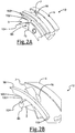
FIG. 2A illustrates a sectional perspective view of a product according to a number of variations. -
FIG. 2B illustrates a sectional perspective view of a product according to a number of variations. -
FIG. 2C illustrates a radial perspective cross-sectional view of a product according to a number of variations. -
FIG. 2D illustrates a sectional perspective view of a product according to a number of variations. -
FIG. 3A illustrates an axial cross-sectional view of a product according to a number of variations. -
FIG. 3B illustrates a sectional perspective view of a product according to a number of variations. -
FIG. 3C illustrates a sectional perspective view of a product according to a number of variations. -
FIG. 4A illustrates a sectional perspective view of a product according to a number of variations. -
FIG. 4B illustrates an axial cross-sectional view of a product according to a number of variations. -
FIG. 4C illustrates an axial cross-sectional view of a product according to a number of variations. -
FIG.4D illustrates a radial cross-sectional view of a product according to a number of variations. -
FIG. 4E illustrates a sectional perspective view of a product according to a number of variations. -
FIG. 4F illustrates a sectional perspective view of a product according to a number of variations. - The following description of the variations is merely illustrative in nature and is in no way intended to limit the scope of the invention, its application, or uses.
- Referring to
FIG. 1 , in a number of variations, aproduct 10 is shown. In a number of variations, theproduct 10 may include aturbomachinery device 10. In a number of variations, the turbomachinery device may be a device that includes a high speed machine that includes a rotor and a fluid and transfers energy from a fluid to a rotor or vice versa. In a number of variations, theturbomachinery device 10 may include at least one of a turbocharger, an electrified turbocharger, a compressor, a turbine, an expansion device, an organic rankine cycle (ORC) device, a motor used in turbomachinery, a booster, an electrified booster, an electrified turbo compound component, or may be another device. In a number of non-limiting variations, as shown inFIG. 1 , theproduct 10 may include a turbocharger 1. In a number of variations, theproduct 10 or turbocharger 1 may include at least one of aturbine 68 and/or at least onecompressor 70, a variation of which is illustrated inFIG. 1 . In a number of variations, theproduct 10 or turbocharger 1 orturbine 68 may comprise a turbine wheel orrotor 4. In a number of variations, theturbocharger 4 orturbine 68 may have variable turbine geometry (VTG). In a number of variations, theproduct 10 or turbocharger 1 orcompressor 70 may comprise a compressor wheel orrotor 17. In a number of variations, the turbine wheel orrotor 4 may be operatively connected to a compressor wheel orrotor 17 through ashaft 36. In a number of variations, theturbine wheel 4 may receive thermodynamic power from exhaust gas from the system and may drive theshaft 36 which may then drive thecompressor wheel 17. In a number of variations, theshaft 36 may be supported for rotation by at least one bearing 38, 40. In a number of variations, theproduct 10 or turbocharger 1 may include a first bearing 38 and a second bearing 40. In a number of variations, theproduct 10 or turbocharger 1 may include aturbine housing 2 and a compressor housing 3 which may be connected to it via abearing housing 19. In a number of variations, theproduct 10 may include abearing lubrication system 72. In a number of variations, afluid 74 may be provided to the first andsecond bearings bearing lubrication system 72 in order to ensure proper rotation of theshaft 36. In a number of variations, thefluid 74 may include oil, coolant, or may be another type. - Still referring to
FIG. 1 , in a number of variations, thehousings FIG. 1 , theturbine housing 2 is shown partially in section in order to illustrate the arrangement of alower ring 6 as part of a radiallyouter vane cascade 18 which may have a plurality ofvanes 7, with pivots orvane posts 8, which may be distributed over the circumference. In a number of variations, avane 7 may include anindividual vane post 8 which may actuate thevane 7 into an "open" or "closed" position. In a number of variations, as shown inFIG. 2D , thevane post 8 may have afirst end 8A and asecond end 8B. As a result of this, in a number of variations, nozzle cross sections may be formed which, depending upon the position of thevanes 7, may be larger or smaller and may expose theturbine rotor 4, which may be mounted in the middle on the rotational axis R, to a greater or lesser extent to the action of the exhaust gas of an engine. In a number of variations, an "open" position may be defined as allowing gas through thevane cascade 18 via an opening created by actuation of thevane 7. In a number of variations, a "closed" position may be defined as allowing no gas through thevane cascade 18 via an opening created by actuation of thevane 7. In a number of variations, the exhaust gas of an engine may be fed via afeed passage 9 and may be discharged via acentral duct 10 in order to drive acompressor rotor 17, which may be seated upon thesame shaft 36, via theturbine rotor 4. - In a number of variations, in order to control the movement or the position of the
vanes 7, theproduct 10 or turbocharger 1 may include anoperating device 11 which may include avane actuator 98. In a number of variations, the operatingdevice 11 may include andECU 150 which may operate the movement or position of thevanes 7 based on conditions within theproduct 10 or its surroundings or applications of theproduct 10. In a number of variations, the operatingdevice 11 may include acontrol housing 12 which may control movement of aram component 14 which may be fastened to it, in order to convert its movement onto a vaneupper ring 5, which may be located behind the vanelower ring 6. In a number of variations, thevane cascade 18 orvanes 7 may be located between theupper ring 5 and thelower ring 6. In a number of variations, thevane cascade 18 or at least onevane 7 may be mechanically coupled to at least one of theupper ring 5 or thelower ring 6. In a number of variations, thevane cascade 18 or at least onevane 7 may be mechanically coupled to theupper ring 5 and thelower ring 6. In a number of variations, thevane cascade 18 or at least onevane 7 may be mechanically coupled to at least one of theupper ring 5 or thelower ring 6 through thevane post 8. In a number of variations, thevane cascade 18 or at least onevane 7 may be mechanically coupled to theupper ring 5 and thelower ring 6 through thevane post 8. In a number of variations, thevane cascade 18 or at least onevane 7 may be mechanically coupled to theupper ring 5 and thelower ring 6 through thevane post 8 where the vane postfirst end 8A mechanically couples theupper ring 5 and the vane postsecond end 8B mechanically couples thelower ring 6. In a number of variations, thevane actuator 98 may include anactuator ring 100. In a number of variations, thevane actuator 98 may move or rotate theactuator ring 100. In a number of variations, thevane actuator 98 may include a plurality of actuator rings 100. In a number of variations, thevane actuator 98 may include thevane cascade 18 and plurality ofvanes 7. In a number of variations, theactuator ring 100 may be between thevane cascade 18 and theupper ring 5. In a number of variations, theactuator ring 100 may be between thevane cascade 18 and thelower ring 6. In a number of variations, theactuator ring 100 may be on the outside of theupper ring 5. In a number of variations, theactuator ring 100 may be on the outside of thelower ring 6. In a number of variations, thevane cascade 18 or at least onevane 7 may be mechanically coupled theactuator ring 100 through thevane post 8 on thefirst end 8A,second end 8B or at another point. In a number of variations, thecontrol housing 12 may control the movement of aram component 14 which may be fastened to it, in order to convert its movement onto theactuator ring 100 and subsequently into an actuation of thevane cascade 19 or at least onevane 7 to an "open" or "closed" position, based on free movement of theactuator ring 100. In a number of variations, afree space 13 for thevanes 7 may be formed between thevane bearing ring 6 and an annular section 25 of theturbine housing 2. In order to be able to safeguard thisfree space 13, thelower ring 6 may have spacers 16 which may be formed in one piece. In a non-limiting exemplary case, three spacers 26 may be arranged on the circumference of thevane bearing ring 6 with an angular spacing of 120° in each case. In principle, however, it may be possible to provide such spacers 26 in a greater or lesser number. - In a number of variations, as shown in
FIGs. 2A-2D , the vane may be between thelower ring 6 and theupper ring 5. In a number of variations, as shown inFig. 2A , theactuator ring 100 may be between at least onevane 7 and theupper ring 5. In a number of variations, as shown inFIG. 2D , thevane post 8 may have afirst end 8A and asecond end 8B. As illustrated inFIGs. 2A and2C , in a number of variations, the vane postfirst end 8A may mechanically couple to theupper ring 5 and thelower post 8B may mechanically couple to thelower ring 6. In a number of variations, as shown inFIGs. 2A ,3A ,4A, 4D, and 4F , theupper ring 5 may include an upper ring bore 15. In a number of variations, as shown inFIGs. 2A ,3A ,4A, 4D, and 4F , thefirst end 8A of thevane post 8 may fit into and mechanically couple to the upper ring bore 15 of theupper ring 5. In a number of variations, as shown inFIGs. 2A, 2B ,2C ,3B ,3C ,4D , thelower ring 6 may include a lower ring bore 16. In a number of variations, as shown inFIGs. 2A, 2B ,3B ,3C , and4D , thesecond end 8B of thevane post 8 may fit into and mechanically couple to the lower ring bore 16 of thelower ring 6. In a number of variations, as shown inFIGS. 2A-2D , thevane post 8 may include at least onegroove 104. In a number of variations, thevane post 8 may include agroove 104 along a longitudinal side of thefirst end 8A. In a number of variations, thevane post 8 may include agroove 104 along a longitudinal side of thesecond end 8B. In a number of variations, theactuator ring 100 may include at least onespline 102. In a number of variations, as shown inFig. 2A, 2B ,4B, and 4C , theactuator ring 8 may include at least onespline 102 along aradial edge 103 of theactuator ring 8. In a number of variations, as shown inFIGS. 2A-2B , thespline 102 of theactuator ring 100 may mechanically couple to thegroove 104 of thevane post 8. In a number of variations, this may mechanically couple theactuator ring 100 to thevane 7. In a number of variations, movement or rotation of theactuator ring 100 may move or rotate the at least onespline 102 which may in turn move or rotate thegroove 104 of thevane post 8 which may move or rotate thevane 7 from an "open" position to a "closed" position and vice versa. In a number of variations, theactuator ring 100 may include a plurality ofsplines 102 mechanically coupled to a plurality ofgrooves 104 onindividual vane posts 8 such that theactuator ring 100 may be mechanically coupled to a plurality ofvanes 7. In a number of variations, each of thegrooves 104 in the vane posts 8 may be mechanically coupled to at least onespline 102 of theactuator ring 100. In a number of variations, theactuator ring 100 may be constructed and arranged to operate a plurality of vanes uniformly based on movement of theactuator ring 100. In a number of variations, the movement of theactuator ring 100 that actuates thevanes 7 may be rotational in a clockwise or counterclockwise direction where one direction "opens" the vanes and the other direction "closes" the vanes. In a number of variations, as shown inFig. 4B-4C , thespline 102 may be in the shape of a dogbone. In a number of variations, thegroove 104 may have a wider length LG to accommodate the dogbone shape. In a number of variations, a dogbone shape may reduce friction and stress between thevanes 7 and theactuator ring 100 during operation. - In a number of variations, as illustrated in
Fig. 4A, 4D, 4E, and 4F , thevane 7 may include abuffer region 120 between thevane post 8 and thevane 7. In a number of variations, as shown inFIG. 4A, 4D, and 4F , thebuffer region 120 may abut an axial surface of theupper ring 5 up to the vane postfirst end 8A as it accepted in the upper ring bore 15. In a number of variations, as shown inFIG. 4A , thebuffer region 120A may be accepted at least partially into the upper ring bore 15. In a number of variations, as shown inFIG. 4D , thebuffer region 120A may abut an axial surface of thelower ring 6 up to the vane postsecond end 8B as it accepted in the lower ring bore 16. In a number of variations, as shown inFIG. 4D , thebuffer region 120B may be accepted at least partially into the lower ring bore 16. In a number of variations, as shown inFIG. 4D , thevane 7 may havedual buffer regions FIG. 4A, 4D, and 4E , the vane postfirst end 8A may project out through the upper ring bore 15. In a number of variations, as shown inFIG. 4E , the vane postfirst end 8A may include a vane post bore 140. In a number of variations, theactuator ring 100 may include at least one axial face spline (not shown) projecting outward from anaxial surface 101 of theactuator ring 100. In a number of variations, the axial face spline of theactuator ring 100 may mechanically couple to the vane post bore 140 of thevane post 8. In a number of variations, this may mechanically couple theactuator ring 100 to thevane 7. In a number of variations, movement or rotation of theactuator ring 100 may move or rotate the at least one axial face spline which may in turn move or rotate the vane post bore 140 of thevane post 8 which may move or rotate thevane 7 from an "open" position to a "closed" position and vice versa. In a number of variations, theactuator ring 100 may include a plurality of axial face splines mechanically coupled to a plurality of vane post bores 140 onindividual vane posts 8 such that theactuator ring 100 may be mechanically coupled to a plurality ofvanes 7. In a number of variations, the axial face spline may include a key. In a number of variations, the vane post bore 140 may include a grooved interior to accept the key on the axial face spline. In a number of variations, the axial face spline may include a groove. In a number of variations, the vane post bore 140 may include an interior key to accept the groove on the axial face spline. In a number of variations, each of the vane post bores 140 in the vane posts 8 may be mechanically coupled to at least one radial face spline of theactuator ring 100. In a number of variations, theactuator ring 100 may be constructed and arranged to operate a plurality of vanes uniformly based on movement of theactuator ring 100. In a number of variations, the movement of theactuator ring 100 that actuates thevanes 7 may be rotational in a clockwise or counterclockwise direction where one direction "opens" the vanes and the other direction "closes" the vanes. - In a number of variations, as shown in
FIGs. 3A-3C , theactuator ring 100 may include agroove 114 that may be formed between a plurality of actuator splines 102. In a number of variations, thevane post 8 may include aspline 112 along a longitudinal side of thefirst end 8A. In a number of variations, thevane post 8 may include aspline 112 along a longitudinal side of thesecond end 8B. In a number of variations, thevane post 8 may include aspline 112 that may mechanically couple to at least one of thegrooves 114 formed in theactuator ring 100. In a number of variations, this may mechanically couple theactuator ring 100 to thevane 7. In a number of variations, movement or rotation of theactuator ring 100 may move or rotate the at least onegroove 114 which may in turn move or rotate thespline 112 of thevane post 8 which may move or rotate thevane 7 from an "open" position to a "closed" position and vice versa. In a number of variations, theactuator ring 100 may include a plurality ofgrooves 114 mechanically coupled to a plurality ofsplines 112 onindividual vane posts 8 such that theactuator ring 100 may be mechanically coupled to a plurality ofvanes 7. In a number of variations, each of thesplines 112 in the vane posts 8 may be mechanically coupled to at least onegroove 114 of theactuator ring 100. In a number of variations, theactuator ring 100 may be constructed and arranged to operate a plurality of vanes uniformly based on movement of theactuator ring 100. In a number of variations, the movement of theactuator ring 100 that actuates thevanes 7 may be rotational. In a number of variations, as shown inFig. 3C , thefirst end 8A of thevane post 8 may be an insert which locks into thevane 7 through akey mechanism 130. - It is also noted that any mechanical coupling of the
actuator ring 100 and thevane post 8 may be undertaken without departing from the scope of the invention including avane actuator 98 involving a nut, bolt, fastener, buckle, button, cable tie, clamp, clip, clutch, flange, frog, grommet, latch, nail, peg, pin, hook and loop fastener, rivet, screw anchor, snap fastener, staple, stitch, strap, threaded fastener, tie, toggle bolt, zipper, wedge anchor or may be another type. In a number of variations, theproduct 10 including any of its components (including thevane actuator 98,vane 7,vane post 8,actuator ring 100,upper ring 5,lower ring 6, or may be another component) may be made of aluminum, cast iron, molded plastic, carbon fiber, other die cast metal, or other suitable material. In a number of variations, the components of the product 10 (including thevane actuator 98,vane 7,vane post 8,actuator ring 100,upper ring 5,lower ring 6, or may be another component) may be secured in the orientations illustrated by staking, casting it in position, machining, assembly, or other suitable means. - In a number of variations, a method 800 is shown. In a number of variations, the method 800 may include in block 802 providing a turbine comprising a lower ring, a upper ring, a plurality of vanes, wherein each of the vanes comprises a vane post mechanically coupling the lower ring and the upper ring to the vane, and a vane actuator comprising an actuator ring constructed and arranged to operate the vanes uniformly based on movement of the actuator ring. In a number of variations, the method 800 may further include, in block 804, actuating the vanes into an open position or a closed position uniformly through movement of the actuator ring.
- In a number of variations,
product 10 orvane actuator 98 may actuator all of thevanes 8 of thevane cascade 18 uniformly, eliminating the need for individual vane levers for each vane, which may reduce cost of manufacture, assembly, and componentry, as well as reduce complexity of theproduct 10 or actuation of thevane cascade 18. In a number of variations, theproduct 10 orvane actuator 98 may lessen or eliminate vane sticking, vane non-actuation, ornon-uniform vane cascade 18 actuation in undesirable conditions such as high or non-uniform temperature environments. - The following description of variants is only illustrative of components, elements, acts, products and methods considered to be within the scope of the invention and are not in any way intended to limit such scope by what is specifically disclosed or not expressly set forth. The components, elements, acts, products and methods as described herein may be combined and rearranged other than as expressly described herein and still are considered to be within the scope of the invention.
- Variation 1 may include a product comprising: a turbine comprising a lower ring, a upper ring, a plurality of vanes, wherein each of the vanes comprises a vane post mechanically coupling the lower ring and the upper ring to the vane, and a vane actuator comprising an actuator ring constructed and arranged to operate the vanes uniformly based on movement of the actuator ring.
-
Variation 2 may include a product as set forth in Variation 1 wherein the actuator ring comprises a plurality of splines. - Variation 3 may include a product as set forth in
Variation 2 wherein each of the vane posts comprises a groove that mechanically couples with at least one spline of the actuator ring. -
Variation 4 may include a product as set forth in any of Variations 1-3 wherein the actuator ring comprises a plurality of grooves. -
Variation 5 may include a product as set forth inVariation 4 wherein each of the vane posts comprises a spline that mechanically couples with at least one groove of the actuator ring. -
Variation 6 may include a product as set forth in any of Variations 2-5 wherein at least one of the splines has a dogbone shape. -
Variation 7 may include a product as set forth in any of Variations 1-6 wherein at least one of the lower ring or the upper ring comprises a bore that mechanically couples to the vane through the vane post. -
Variation 8 may include a product as set forth in any of Variations 2-7 wherein the vane post comprises a bore that mechanically couples with at least one spline of the actuator ring. -
Variation 9 may include a product as set forth in any of Variations 1-8 wherein product comprises a turbocharger. -
Variation 10 may include a product as set forth in any of Variations 1-9 wherein turbine has variable turbine geometry. -
Variation 11 may include a method comprising: providing a turbine comprising a lower ring, a upper ring, a plurality of vanes, wherein each of the vanes comprises a vane post mechanically coupling the lower ring and the upper ring to the vane, and a vane actuator comprising an actuator ring constructed and arranged to operate the vanes uniformly based on movement of the actuator ring; and actuating the vanes into an open position or a closed position uniformly through movement of the actuator ring. -
Variation 12 may include a method as set forth inVariation 11 wherein the actuator ring comprises a plurality of splines. -
Variation 13 may include a method as set forth inVariation 12 wherein each of the vane posts comprises a groove that mechanically couples with at least one spline of the actuator ring. -
Variation 14 may include a method as set forth in any of Variations 11-13 wherein the actuator ring comprises a plurality of grooves. -
Variation 15 may include a method as set forth inVariation 14 wherein each of the vane posts comprises a spline that mechanically couples with at least one groove of the actuator ring. -
Variation 16 may include a method as set forth in any of Variations 12-15 wherein at least one of the splines has a dogbone shape. -
Variation 17 may include a method as set forth in any of Variations 11-16 wherein at least one of the lower ring or the upper ring comprises a bore that mechanically couples to the vane through the vane post. -
Variation 18 may include a method as set forth in any of Variations 12-17 wherein the vane post comprises a bore that mechanically couples with at least one spline of the actuator ring. -
Variation 19 may include a method as set forth in any of Variations 11-18 wherein product comprises a turbocharger. - Variation 20 may include a method as set forth in any of Variations 11-19 wherein turbine has variable turbine geometry.
- The above description of select variations within the scope of the invention is merely illustrative in nature and, thus, variations or variants thereof are not to be regarded as a departure from the spirit and scope of the invention.
Claims (15)
- A product comprising:a turbine comprising a lower ring, a upper ring, a plurality of vanes, wherein each of the vanes comprises a vane post mechanically coupling the lower ring and the upper ring to the vane, and a vane actuator comprising an actuator ring constructed and arranged to operate the vanes uniformly based on movement of the actuator ring.
- The product of claim 1 wherein the actuator ring comprises a plurality of splines.
- The product of claim 2 wherein each of the vane posts comprises a groove that mechanically couples with at least one spline of the actuator ring.
- The product of claim 1 or claim 2 wherein the actuator ring comprises a plurality of grooves.
- The product of claim 4 wherein each of the vane posts comprises a spline that mechanically couples with at least one groove of the actuator ring.
- The product of any one of the preceding claims wherein at least one of the lower ring or the upper ring comprises a bore that mechanically couples to the vane through the vane post.
- The product of claim 2 wherein the vane post comprises a bore that mechanically couples with at least one spline of the actuator ring.
- The product of any one of the preceding claims wherein product comprises a turbocharger, in particular wherein the turbine has variable turbine geometry.
- A method comprising:providing a turbine comprising a lower ring, a upper ring, a plurality of vanes, wherein each of the vanes comprises a vane post mechanically coupling the lower ring and the upper ring to the vane, and a vane actuator comprising an actuator ring constructed and arranged to operate the vanes uniformly based on movement of the actuator ring; andactuating the vanes into an open position or a closed position uniformly through movement of the actuator ring.
- The method of claim 9 wherein the actuator ring comprises a plurality of splines.
- The method of claim 10 wherein each of the vane posts comprises a groove that mechanically couples with at least one spline of the actuator ring.
- The method of claim 9 or claim 10 wherein the actuator ring comprises a plurality of grooves.
- The method of claim 12 wherein each of the vane posts comprises a spline that mechanically couples with at least one groove of the actuator ring.
- The method of any one of claims 9 to 13 wherein at least one of the lower ring or the upper ring comprises a bore that mechanically couples to the vane through the vane post.
- The method of any one of claims 9 to 14 wherein product comprises a turbocharger, in particular wherein turbine has variable turbine geometry.
Applications Claiming Priority (1)
| Application Number | Priority Date | Filing Date | Title |
|---|---|---|---|
| US15/244,469 US20180058247A1 (en) | 2016-08-23 | 2016-08-23 | Vane actuator and method of making and using the same |
Publications (2)
| Publication Number | Publication Date |
|---|---|
| EP3287607A1 true EP3287607A1 (en) | 2018-02-28 |
| EP3287607B1 EP3287607B1 (en) | 2019-06-19 |
Family
ID=59034451
Family Applications (1)
| Application Number | Title | Priority Date | Filing Date |
|---|---|---|---|
| EP17173799.2A Active EP3287607B1 (en) | 2016-08-23 | 2017-05-31 | Vane actuator and method of making and using the same |
Country Status (5)
| Country | Link |
|---|---|
| US (1) | US20180058247A1 (en) |
| EP (1) | EP3287607B1 (en) |
| JP (1) | JP2018031372A (en) |
| KR (1) | KR20180022561A (en) |
| CN (1) | CN107762567A (en) |
Families Citing this family (2)
| Publication number | Priority date | Publication date | Assignee | Title |
|---|---|---|---|---|
| US10927702B1 (en) | 2019-03-30 | 2021-02-23 | Savant Holdings LLC | Turbocharger or turbocharger component |
| US12209599B1 (en) | 2023-03-22 | 2025-01-28 | Savant Holdings LLC | Multi-stage actuator for a turbocharger |
Citations (4)
| Publication number | Priority date | Publication date | Assignee | Title |
|---|---|---|---|---|
| EP2573363A2 (en) * | 2011-09-26 | 2013-03-27 | Honeywell International Inc. | Turbocharger variable-nozzle assembly with vane sealing arrangement |
| WO2013116136A1 (en) * | 2012-02-02 | 2013-08-08 | Borgwarner Inc. | Mixed-flow turbocharger with variable turbine geometry |
| WO2014107270A1 (en) * | 2013-01-04 | 2014-07-10 | Borgwarner Inc. | Variable pivot center vtg vanes and vane pack assembly |
| WO2015080920A1 (en) * | 2013-11-26 | 2015-06-04 | Borgwarner Inc. | Vtg turbocharger with wastegate controlled by a common actuator |
Family Cites Families (37)
| Publication number | Priority date | Publication date | Assignee | Title |
|---|---|---|---|---|
| US3033519A (en) * | 1958-09-12 | 1962-05-08 | United Aircraft Corp | Turbine nozzle vane construction |
| US3101926A (en) * | 1960-09-01 | 1963-08-27 | Garrett Corp | Variable area nozzle device |
| US3318574A (en) * | 1964-11-30 | 1967-05-09 | Canadian Patents Dev | Gas turbine |
| US4378960A (en) * | 1980-05-13 | 1983-04-05 | Teledyne Industries, Inc. | Variable geometry turbine inlet nozzle |
| JPS597708A (en) * | 1982-07-07 | 1984-01-14 | Hitachi Ltd | Mounting angle variable device of stationary blade in axial flow machine |
| US4659295A (en) * | 1984-04-20 | 1987-04-21 | The Garrett Corporation | Gas seal vanes of variable nozzle turbine |
| DE3513823C1 (en) * | 1985-04-17 | 1986-10-02 | Mtu Motoren- Und Turbinen-Union Friedrichshafen Gmbh, 7990 Friedrichshafen | Flow machine |
| US4695220A (en) * | 1985-09-13 | 1987-09-22 | General Electric Company | Actuator for variable vanes |
| US4726744A (en) * | 1985-10-24 | 1988-02-23 | Household Manufacturing, Inc. | Tubocharger with variable vane |
| US4804316A (en) * | 1985-12-11 | 1989-02-14 | Allied-Signal Inc. | Suspension for the pivoting vane actuation mechanism of a variable nozzle turbocharger |
| US4741666A (en) * | 1985-12-23 | 1988-05-03 | Ishikawajima-Harima Jukogyo Kabushiki Kaisha | Variable displacement turbocharger |
| US4668165A (en) * | 1986-03-27 | 1987-05-26 | The United States Of America As Represented By The Secretary Of The Air Force | Super gripper variable vane arm |
| GB8722714D0 (en) * | 1987-09-26 | 1987-11-04 | Rolls Royce Plc | Variable guide vane arrangement for compressor |
| US5214920A (en) * | 1990-11-27 | 1993-06-01 | Leavesley Malcolm G | Turbocharger apparatus |
| DE19752534C1 (en) * | 1997-11-27 | 1998-10-08 | Daimler Benz Ag | Radial flow turbocharger turbine for internal combustion engine |
| JP3686300B2 (en) * | 2000-02-03 | 2005-08-24 | 三菱重工業株式会社 | Centrifugal compressor |
| JP2001329851A (en) * | 2000-05-19 | 2001-11-30 | Mitsubishi Heavy Ind Ltd | Variable nozzle mechanism for variable displacement turbine |
| DE10104176A1 (en) * | 2001-01-24 | 2002-07-25 | Mahle Gmbh | Guide blade adjusting device for turbocharger ha adjusting ring with projecting noses for axial guidance of ring on blade carrier plate |
| JP3764653B2 (en) * | 2001-02-27 | 2006-04-12 | 三菱重工業株式会社 | NOZZLE OPENING REGULATION DEVICE FOR VARIABLE NOZZLE MECHANISM AND ITS MANUFACTURING METHOD |
| JP3735262B2 (en) * | 2001-02-27 | 2006-01-18 | 三菱重工業株式会社 | Variable nozzle mechanism for variable capacity turbine and manufacturing method thereof |
| EP1396621B1 (en) * | 2001-05-10 | 2015-09-09 | Akita Fine Blanking Co., Ltd. | Surface-reformed exhaust gas guide assembly of vgs type turbo charger, and method of surface-reforming component member thereof |
| CN1192172C (en) * | 2001-07-27 | 2005-03-09 | 三菱重工业株式会社 | Centrifugal compressor |
| US6527508B2 (en) * | 2001-08-03 | 2003-03-04 | Mark Groskreutz | Actuator crank arm design for variable nozzle turbocharger |
| JP3933455B2 (en) * | 2001-11-30 | 2007-06-20 | 株式会社小松製作所 | Variable turbocharger |
| US6619916B1 (en) * | 2002-02-28 | 2003-09-16 | General Electric Company | Methods and apparatus for varying gas turbine engine inlet air flow |
| EP1549826B1 (en) * | 2002-09-18 | 2008-09-17 | Honeywell International Inc. | Variable nozzle device for a turbocharger and method for operating the same |
| DE102004057864A1 (en) * | 2004-11-30 | 2006-06-01 | Borgwarner Inc.(N.D.Ges.D.Staates Delaware), Auburn Hills | Exhaust gas turbocharger, distributor for an exhaust gas turbocharger and blade lever for a distributor |
| EP1669548A1 (en) * | 2004-12-08 | 2006-06-14 | ABB Turbo Systems AG | Guide vane apparatus for a gas turbine engine |
| EP1811135A1 (en) * | 2006-01-23 | 2007-07-25 | ABB Turbo Systems AG | Variable guiding device |
| EP1811134A1 (en) * | 2006-01-23 | 2007-07-25 | ABB Turbo Systems AG | Variable guiding device |
| EP1816317B1 (en) * | 2006-02-02 | 2013-06-12 | IHI Corporation | Turbocharger with variable nozzle |
| US7571607B2 (en) * | 2006-03-06 | 2009-08-11 | Honeywell International Inc. | Two-shaft turbocharger |
| EP1840386A1 (en) * | 2006-03-31 | 2007-10-03 | ABB Turbo Systems AG | Pre-swirl device |
| FR2904668B1 (en) * | 2006-08-02 | 2008-10-31 | Snecma Sa | VANE CONTROL DEVICE WITH VARIABLE ROTATION ANGLE OF TURBOMACHINE WITH CYLINDRICAL ROD |
| US8764402B2 (en) * | 2011-06-09 | 2014-07-01 | General Electric Company | Turbomachine blade locking system |
| US9074489B2 (en) * | 2012-03-26 | 2015-07-07 | Pratt & Whitney Canada Corp. | Connector assembly for variable inlet guide vanes and method |
| JP5836317B2 (en) * | 2013-05-16 | 2015-12-24 | 株式会社豊田自動織機 | Variable nozzle turbocharger |
-
2016
- 2016-08-23 US US15/244,469 patent/US20180058247A1/en not_active Abandoned
-
2017
- 2017-05-31 EP EP17173799.2A patent/EP3287607B1/en active Active
- 2017-07-31 KR KR1020170096649A patent/KR20180022561A/en not_active Withdrawn
- 2017-08-03 CN CN201710656281.XA patent/CN107762567A/en active Pending
- 2017-08-04 JP JP2017151276A patent/JP2018031372A/en active Pending
Patent Citations (4)
| Publication number | Priority date | Publication date | Assignee | Title |
|---|---|---|---|---|
| EP2573363A2 (en) * | 2011-09-26 | 2013-03-27 | Honeywell International Inc. | Turbocharger variable-nozzle assembly with vane sealing arrangement |
| WO2013116136A1 (en) * | 2012-02-02 | 2013-08-08 | Borgwarner Inc. | Mixed-flow turbocharger with variable turbine geometry |
| WO2014107270A1 (en) * | 2013-01-04 | 2014-07-10 | Borgwarner Inc. | Variable pivot center vtg vanes and vane pack assembly |
| WO2015080920A1 (en) * | 2013-11-26 | 2015-06-04 | Borgwarner Inc. | Vtg turbocharger with wastegate controlled by a common actuator |
Also Published As
| Publication number | Publication date |
|---|---|
| KR20180022561A (en) | 2018-03-06 |
| EP3287607B1 (en) | 2019-06-19 |
| US20180058247A1 (en) | 2018-03-01 |
| CN107762567A (en) | 2018-03-06 |
| JP2018031372A (en) | 2018-03-01 |
Similar Documents
| Publication | Publication Date | Title |
|---|---|---|
| US7901178B2 (en) | Inner diameter vane shroud system having enclosed synchronizing mechanism | |
| EP1757776B1 (en) | Lightweight cast inner diameter vane shroud for variable stator vanes | |
| US9729035B2 (en) | Electric motor rotor | |
| KR101864241B1 (en) | Exhaust-gas turbocharger | |
| US10669882B2 (en) | Variable stator blade operating device | |
| EP2794182A1 (en) | Support structure for a gas turbine engine | |
| EP2861831B1 (en) | Rotor assembly with interlocking tabs | |
| US20180087531A1 (en) | Turbocharger | |
| KR20140050679A (en) | Exhaust-gas turbocharger | |
| EP3287607B1 (en) | Vane actuator and method of making and using the same | |
| US9689274B2 (en) | Variable geometry turbine | |
| CN101680356B (en) | Variable geometry turbocharger with isolated components | |
| US20130239569A1 (en) | Gas expander system | |
| US8511971B2 (en) | One-piece compressor and turbine containment system | |
| WO2012051997A2 (en) | Turbine wheel arrangement for a gas turbine | |
| US7578655B1 (en) | Composite gas turbine fan blade | |
| US10519808B2 (en) | Turbocharger | |
| US20110158814A1 (en) | Turbine engine rotor blades and rotor wheels | |
| EP2877727B1 (en) | Top hat bearing retainer for variable vane actuator | |
| WO2018208609A1 (en) | Backplate and method of making and using the same | |
| KR101998630B1 (en) | Exhaust-gas turbocharger | |
| JP5703923B2 (en) | Scroll housing positioning structure and supercharger | |
| EP3597930B1 (en) | Cam isolation system for gas turbine engine compressor section | |
| GB2544033A (en) | Mounting a component to a shaft | |
| US20180245482A1 (en) | Turbocharger |
Legal Events
| Date | Code | Title | Description |
|---|---|---|---|
| PUAI | Public reference made under article 153(3) epc to a published international application that has entered the european phase |
Free format text: ORIGINAL CODE: 0009012 |
|
| STAA | Information on the status of an ep patent application or granted ep patent |
Free format text: STATUS: REQUEST FOR EXAMINATION WAS MADE |
|
| 17P | Request for examination filed |
Effective date: 20170531 |
|
| AK | Designated contracting states |
Kind code of ref document: A1 Designated state(s): AL AT BE BG CH CY CZ DE DK EE ES FI FR GB GR HR HU IE IS IT LI LT LU LV MC MK MT NL NO PL PT RO RS SE SI SK SM TR |
|
| AX | Request for extension of the european patent |
Extension state: BA ME |
|
| RIC1 | Information provided on ipc code assigned before grant |
Ipc: F01D 17/16 20060101ALI20181129BHEP Ipc: F01D 17/00 20060101AFI20181129BHEP |
|
| GRAP | Despatch of communication of intention to grant a patent |
Free format text: ORIGINAL CODE: EPIDOSNIGR1 |
|
| STAA | Information on the status of an ep patent application or granted ep patent |
Free format text: STATUS: GRANT OF PATENT IS INTENDED |
|
| INTG | Intention to grant announced |
Effective date: 20190108 |
|
| RIN1 | Information on inventor provided before grant (corrected) |
Inventor name: ROTH, ROLAND Inventor name: KARAMAVRUC, ALIIHSAN Inventor name: KIEFER, CLEMENT |
|
| GRAS | Grant fee paid |
Free format text: ORIGINAL CODE: EPIDOSNIGR3 |
|
| GRAA | (expected) grant |
Free format text: ORIGINAL CODE: 0009210 |
|
| STAA | Information on the status of an ep patent application or granted ep patent |
Free format text: STATUS: THE PATENT HAS BEEN GRANTED |
|
| AK | Designated contracting states |
Kind code of ref document: B1 Designated state(s): AL AT BE BG CH CY CZ DE DK EE ES FI FR GB GR HR HU IE IS IT LI LT LU LV MC MK MT NL NO PL PT RO RS SE SI SK SM TR |
|
| REG | Reference to a national code |
Ref country code: GB Ref legal event code: FG4D |
|
| REG | Reference to a national code |
Ref country code: CH Ref legal event code: EP |
|
| REG | Reference to a national code |
Ref country code: IE Ref legal event code: FG4D |
|
| REG | Reference to a national code |
Ref country code: AT Ref legal event code: REF Ref document number: 1145776 Country of ref document: AT Kind code of ref document: T Effective date: 20190715 |
|
| REG | Reference to a national code |
Ref country code: DE Ref legal event code: R096 Ref document number: 602017004579 Country of ref document: DE |
|
| REG | Reference to a national code |
Ref country code: NL Ref legal event code: FP |
|
| PG25 | Lapsed in a contracting state [announced via postgrant information from national office to epo] |
Ref country code: AL Free format text: LAPSE BECAUSE OF FAILURE TO SUBMIT A TRANSLATION OF THE DESCRIPTION OR TO PAY THE FEE WITHIN THE PRESCRIBED TIME-LIMIT Effective date: 20190619 Ref country code: HR Free format text: LAPSE BECAUSE OF FAILURE TO SUBMIT A TRANSLATION OF THE DESCRIPTION OR TO PAY THE FEE WITHIN THE PRESCRIBED TIME-LIMIT Effective date: 20190619 Ref country code: SE Free format text: LAPSE BECAUSE OF FAILURE TO SUBMIT A TRANSLATION OF THE DESCRIPTION OR TO PAY THE FEE WITHIN THE PRESCRIBED TIME-LIMIT Effective date: 20190619 Ref country code: NO Free format text: LAPSE BECAUSE OF FAILURE TO SUBMIT A TRANSLATION OF THE DESCRIPTION OR TO PAY THE FEE WITHIN THE PRESCRIBED TIME-LIMIT Effective date: 20190919 Ref country code: FI Free format text: LAPSE BECAUSE OF FAILURE TO SUBMIT A TRANSLATION OF THE DESCRIPTION OR TO PAY THE FEE WITHIN THE PRESCRIBED TIME-LIMIT Effective date: 20190619 Ref country code: LT Free format text: LAPSE BECAUSE OF FAILURE TO SUBMIT A TRANSLATION OF THE DESCRIPTION OR TO PAY THE FEE WITHIN THE PRESCRIBED TIME-LIMIT Effective date: 20190619 |
|
| REG | Reference to a national code |
Ref country code: LT Ref legal event code: MG4D |
|
| PG25 | Lapsed in a contracting state [announced via postgrant information from national office to epo] |
Ref country code: RS Free format text: LAPSE BECAUSE OF FAILURE TO SUBMIT A TRANSLATION OF THE DESCRIPTION OR TO PAY THE FEE WITHIN THE PRESCRIBED TIME-LIMIT Effective date: 20190619 Ref country code: LV Free format text: LAPSE BECAUSE OF FAILURE TO SUBMIT A TRANSLATION OF THE DESCRIPTION OR TO PAY THE FEE WITHIN THE PRESCRIBED TIME-LIMIT Effective date: 20190619 Ref country code: BG Free format text: LAPSE BECAUSE OF FAILURE TO SUBMIT A TRANSLATION OF THE DESCRIPTION OR TO PAY THE FEE WITHIN THE PRESCRIBED TIME-LIMIT Effective date: 20190919 Ref country code: GR Free format text: LAPSE BECAUSE OF FAILURE TO SUBMIT A TRANSLATION OF THE DESCRIPTION OR TO PAY THE FEE WITHIN THE PRESCRIBED TIME-LIMIT Effective date: 20190920 |
|
| REG | Reference to a national code |
Ref country code: AT Ref legal event code: MK05 Ref document number: 1145776 Country of ref document: AT Kind code of ref document: T Effective date: 20190619 |
|
| PG25 | Lapsed in a contracting state [announced via postgrant information from national office to epo] |
Ref country code: AT Free format text: LAPSE BECAUSE OF FAILURE TO SUBMIT A TRANSLATION OF THE DESCRIPTION OR TO PAY THE FEE WITHIN THE PRESCRIBED TIME-LIMIT Effective date: 20190619 Ref country code: EE Free format text: LAPSE BECAUSE OF FAILURE TO SUBMIT A TRANSLATION OF THE DESCRIPTION OR TO PAY THE FEE WITHIN THE PRESCRIBED TIME-LIMIT Effective date: 20190619 Ref country code: PT Free format text: LAPSE BECAUSE OF FAILURE TO SUBMIT A TRANSLATION OF THE DESCRIPTION OR TO PAY THE FEE WITHIN THE PRESCRIBED TIME-LIMIT Effective date: 20191021 Ref country code: SK Free format text: LAPSE BECAUSE OF FAILURE TO SUBMIT A TRANSLATION OF THE DESCRIPTION OR TO PAY THE FEE WITHIN THE PRESCRIBED TIME-LIMIT Effective date: 20190619 Ref country code: RO Free format text: LAPSE BECAUSE OF FAILURE TO SUBMIT A TRANSLATION OF THE DESCRIPTION OR TO PAY THE FEE WITHIN THE PRESCRIBED TIME-LIMIT Effective date: 20190619 Ref country code: CZ Free format text: LAPSE BECAUSE OF FAILURE TO SUBMIT A TRANSLATION OF THE DESCRIPTION OR TO PAY THE FEE WITHIN THE PRESCRIBED TIME-LIMIT Effective date: 20190619 |
|
| PG25 | Lapsed in a contracting state [announced via postgrant information from national office to epo] |
Ref country code: ES Free format text: LAPSE BECAUSE OF FAILURE TO SUBMIT A TRANSLATION OF THE DESCRIPTION OR TO PAY THE FEE WITHIN THE PRESCRIBED TIME-LIMIT Effective date: 20190619 Ref country code: SM Free format text: LAPSE BECAUSE OF FAILURE TO SUBMIT A TRANSLATION OF THE DESCRIPTION OR TO PAY THE FEE WITHIN THE PRESCRIBED TIME-LIMIT Effective date: 20190619 Ref country code: IS Free format text: LAPSE BECAUSE OF FAILURE TO SUBMIT A TRANSLATION OF THE DESCRIPTION OR TO PAY THE FEE WITHIN THE PRESCRIBED TIME-LIMIT Effective date: 20191019 |
|
| PG25 | Lapsed in a contracting state [announced via postgrant information from national office to epo] |
Ref country code: TR Free format text: LAPSE BECAUSE OF FAILURE TO SUBMIT A TRANSLATION OF THE DESCRIPTION OR TO PAY THE FEE WITHIN THE PRESCRIBED TIME-LIMIT Effective date: 20190619 |
|
| PG25 | Lapsed in a contracting state [announced via postgrant information from national office to epo] |
Ref country code: PL Free format text: LAPSE BECAUSE OF FAILURE TO SUBMIT A TRANSLATION OF THE DESCRIPTION OR TO PAY THE FEE WITHIN THE PRESCRIBED TIME-LIMIT Effective date: 20190619 Ref country code: DK Free format text: LAPSE BECAUSE OF FAILURE TO SUBMIT A TRANSLATION OF THE DESCRIPTION OR TO PAY THE FEE WITHIN THE PRESCRIBED TIME-LIMIT Effective date: 20190619 |
|
| PG25 | Lapsed in a contracting state [announced via postgrant information from national office to epo] |
Ref country code: IS Free format text: LAPSE BECAUSE OF FAILURE TO SUBMIT A TRANSLATION OF THE DESCRIPTION OR TO PAY THE FEE WITHIN THE PRESCRIBED TIME-LIMIT Effective date: 20200224 |
|
| REG | Reference to a national code |
Ref country code: DE Ref legal event code: R097 Ref document number: 602017004579 Country of ref document: DE |
|
| PLBE | No opposition filed within time limit |
Free format text: ORIGINAL CODE: 0009261 |
|
| STAA | Information on the status of an ep patent application or granted ep patent |
Free format text: STATUS: NO OPPOSITION FILED WITHIN TIME LIMIT |
|
| PG2D | Information on lapse in contracting state deleted |
Ref country code: IS |
|
| 26N | No opposition filed |
Effective date: 20200603 |
|
| PG25 | Lapsed in a contracting state [announced via postgrant information from national office to epo] |
Ref country code: SI Free format text: LAPSE BECAUSE OF FAILURE TO SUBMIT A TRANSLATION OF THE DESCRIPTION OR TO PAY THE FEE WITHIN THE PRESCRIBED TIME-LIMIT Effective date: 20190619 |
|
| PG25 | Lapsed in a contracting state [announced via postgrant information from national office to epo] |
Ref country code: CH Free format text: LAPSE BECAUSE OF NON-PAYMENT OF DUE FEES Effective date: 20200531 Ref country code: MC Free format text: LAPSE BECAUSE OF FAILURE TO SUBMIT A TRANSLATION OF THE DESCRIPTION OR TO PAY THE FEE WITHIN THE PRESCRIBED TIME-LIMIT Effective date: 20190619 Ref country code: LI Free format text: LAPSE BECAUSE OF NON-PAYMENT OF DUE FEES Effective date: 20200531 |
|
| REG | Reference to a national code |
Ref country code: BE Ref legal event code: MM Effective date: 20200531 |
|
| PG25 | Lapsed in a contracting state [announced via postgrant information from national office to epo] |
Ref country code: LU Free format text: LAPSE BECAUSE OF NON-PAYMENT OF DUE FEES Effective date: 20200531 |
|
| PG25 | Lapsed in a contracting state [announced via postgrant information from national office to epo] |
Ref country code: IE Free format text: LAPSE BECAUSE OF NON-PAYMENT OF DUE FEES Effective date: 20200531 |
|
| PG25 | Lapsed in a contracting state [announced via postgrant information from national office to epo] |
Ref country code: BE Free format text: LAPSE BECAUSE OF NON-PAYMENT OF DUE FEES Effective date: 20200531 |
|
| PGFP | Annual fee paid to national office [announced via postgrant information from national office to epo] |
Ref country code: FR Payment date: 20210420 Year of fee payment: 5 Ref country code: IT Payment date: 20210513 Year of fee payment: 5 Ref country code: DE Payment date: 20210413 Year of fee payment: 5 |
|
| PGFP | Annual fee paid to national office [announced via postgrant information from national office to epo] |
Ref country code: GB Payment date: 20210428 Year of fee payment: 5 |
|
| PGFP | Annual fee paid to national office [announced via postgrant information from national office to epo] |
Ref country code: NL Payment date: 20210415 Year of fee payment: 5 |
|
| PG25 | Lapsed in a contracting state [announced via postgrant information from national office to epo] |
Ref country code: MT Free format text: LAPSE BECAUSE OF FAILURE TO SUBMIT A TRANSLATION OF THE DESCRIPTION OR TO PAY THE FEE WITHIN THE PRESCRIBED TIME-LIMIT Effective date: 20190619 Ref country code: CY Free format text: LAPSE BECAUSE OF FAILURE TO SUBMIT A TRANSLATION OF THE DESCRIPTION OR TO PAY THE FEE WITHIN THE PRESCRIBED TIME-LIMIT Effective date: 20190619 |
|
| PG25 | Lapsed in a contracting state [announced via postgrant information from national office to epo] |
Ref country code: MK Free format text: LAPSE BECAUSE OF FAILURE TO SUBMIT A TRANSLATION OF THE DESCRIPTION OR TO PAY THE FEE WITHIN THE PRESCRIBED TIME-LIMIT Effective date: 20190619 |
|
| REG | Reference to a national code |
Ref country code: DE Ref legal event code: R119 Ref document number: 602017004579 Country of ref document: DE |
|
| REG | Reference to a national code |
Ref country code: NL Ref legal event code: MM Effective date: 20220601 |
|
| GBPC | Gb: european patent ceased through non-payment of renewal fee |
Effective date: 20220531 |
|
| PG25 | Lapsed in a contracting state [announced via postgrant information from national office to epo] |
Ref country code: FR Free format text: LAPSE BECAUSE OF NON-PAYMENT OF DUE FEES Effective date: 20220531 |
|
| PG25 | Lapsed in a contracting state [announced via postgrant information from national office to epo] |
Ref country code: GB Free format text: LAPSE BECAUSE OF NON-PAYMENT OF DUE FEES Effective date: 20220531 Ref country code: DE Free format text: LAPSE BECAUSE OF NON-PAYMENT OF DUE FEES Effective date: 20221201 |
|
| PG25 | Lapsed in a contracting state [announced via postgrant information from national office to epo] |
Ref country code: NL Free format text: LAPSE BECAUSE OF NON-PAYMENT OF DUE FEES Effective date: 20220601 |
|
| PG25 | Lapsed in a contracting state [announced via postgrant information from national office to epo] |
Ref country code: IT Free format text: LAPSE BECAUSE OF NON-PAYMENT OF DUE FEES Effective date: 20220531 |