EP3287097A1 - Verfahren zur kephalometrischen bestimmung einer kenngrösse eines individuums - Google Patents
Verfahren zur kephalometrischen bestimmung einer kenngrösse eines individuums Download PDFInfo
- Publication number
- EP3287097A1 EP3287097A1 EP17186204.8A EP17186204A EP3287097A1 EP 3287097 A1 EP3287097 A1 EP 3287097A1 EP 17186204 A EP17186204 A EP 17186204A EP 3287097 A1 EP3287097 A1 EP 3287097A1
- Authority
- EP
- European Patent Office
- Prior art keywords
- reference point
- cej2
- determining
- incisor
- cej
- Prior art date
- Legal status (The legal status is an assumption and is not a legal conclusion. Google has not performed a legal analysis and makes no representation as to the accuracy of the status listed.)
- Granted
Links
Images


Classifications
-
- A—HUMAN NECESSITIES
- A61—MEDICAL OR VETERINARY SCIENCE; HYGIENE
- A61C—DENTISTRY; APPARATUS OR METHODS FOR ORAL OR DENTAL HYGIENE
- A61C19/00—Dental auxiliary appliances
- A61C19/04—Measuring instruments specially adapted for dentistry
-
- A—HUMAN NECESSITIES
- A61—MEDICAL OR VETERINARY SCIENCE; HYGIENE
- A61C—DENTISTRY; APPARATUS OR METHODS FOR ORAL OR DENTAL HYGIENE
- A61C9/00—Impression cups, i.e. impression trays; Impression methods
- A61C9/004—Means or methods for taking digitized impressions
- A61C9/0046—Data acquisition means or methods
Definitions
- the invention relates to a method for the cephalometric determination of a characteristic of an individual. It also relates to the use of a risk value to assess the risk of gum and / or bone wasting on an incisor of a patient. It also relates to a method for assessing the risk of gum and / or bone wasting on an incisor of a patient.
- the methods according to the invention and the use according to the invention can be used in particular before orthodontic and / or periodontal therapy.
- orthodontics are the most commonly used lateral cephalograms [4a, 4b].
- the most computer-aided measurement is performed using commercial programs such as Dolphin Imaging & Management Solutions (CA, USA) and FRWin (Computerlinger AG, Germany). Since recessions occur most often in the lower anterior region, especially after orthodontic therapy, but also due to age, the determination of the "ideal mandibular anterior position" is of particular interest.
- Another method is to diagnose using photos or to incorporate photos in combination with cephalograms [9a, 9b]. It has been found that a reduced lower anterior face height [10, 11, 12, 13, 14] and a high lip line [11, 13, 15, 16, 17] are likely to be those parameters which are most frequently mentioned in connection with tooth position. In addition, many studies have found relatively large inter-subject variability or conflicting results with respect to most of the evaluated cephalometric parameters. Thus, all procedures that do not judge a direct tooth position or bone thickness are very imprecise.
- auxiliary devices have also been developed which should allow diagnosis of the incisor position directly from the dental crown. These can be done on tooth models or directly in the mouth. But even an application of auxiliary equipment allows no correlation between the axial position of the teeth and the existing bone supply. The method of measuring the tooth crown has no relation to the bone or the gingiva [18, 19, 20].
- Computed tomography or digital volume tomography (DVT) allows a three-dimensional representation of the tooth and bone.
- CT computed tomography
- DVD digital volume tomography
- a targeted measurement of the bone thickness as well as a determination of the bone loss after the treatment is possible.
- current methods do not allow correlation to the tooth position [21, 12, 23, 24]. Alone by the static determination of tooth position and bone thickness, a prognosis for a tooth movement is not possible.
- the object of the invention is to eliminate the disadvantages of the prior art.
- a method for the cephalometric determination of a characteristic of an individual should be specified, which enables a reliable assessment of the risk of gum and / or bone wasting on an incisor of a patient. It is also intended to specify the use of a risk score to assess the risk of gum and / or bone wasting on an incisor of a patient.
- a method for assessing the risk of gum and / or bone wasting on an incisor of a patient should be provided.
- the invention makes it possible to determine the anterior alveolar bone supply by measuring lateral cephalograms or other two-dimensional or three-dimensional images. Such a finding can be used, for example, for a prognosis of the anterior end position to be expected after orthodontic or periodontal therapy, with the probability, in all likelihood, of the expected periodontal recession.
- the individual may be a patient. However, it is not absolutely necessary for the individual whose admission is used to carry out the method according to the invention to be subjected to a dental, in particular orthodontic or periodontal therapy, even if the method according to the invention can preferably be used to prepare such a therapy. In this case, the method according to the invention allows a therapy prognosis with regard to avoiding the emergence of a recession.
- the method according to the invention makes it possible to establish the correlation of directly affected dental and skeletal reference points.
- the first reference point aL1 and the third reference point CEJ are dental reference points
- the second reference point B is a skeletal reference point
- the fourth reference point CEJ2 is a reference point derived from the third reference point.
- cementoenamel junction is meant the tooth-formed boundary between tooth enamel coating the crown of a tooth and tooth tissue covering the roots of a tooth.
- the third reference point CEJ lies on the enamel border of an incisor tooth. It can be provided that the third reference point CEJ is the lowest point and / or the most anterior point of the enamel border in the image used.
- the average height of dehiscence in healthy subjects was 1.8 ⁇ 0.5 mm. It is therefore appropriate to have a distance value between the third reference point CEJ and the fourth reference point CEJ2, which is in a range of 1.3 to 2.3 mm. Preferably, the distance value between the third reference point CEJ and the fourth reference point CEJ2 is 2 mm. Alternatively, however, it may be provided that the distance value is determined as a function of the depth of the sulcus surrounding the incisor.
- the two-dimensional or three-dimensional image used according to the invention is preferably prepared by means of an X-ray method.
- the two-dimensional image may be a cephalometric side image.
- the three-dimensional image can be made using computed tomography ("CT"), magnetic resonance imaging, dental volume tomography ("DVT”) or other three-dimensional imaging techniques.
- CT computed tomography
- DVD dental volume tomography
- the two-dimensional or three-dimensional image is preferably a cephalometric lateral image, a three-dimensional CT image or a three-dimensional CBCT image.
- the cephalometric side image preferably shows a laterolateral image of the head of an individual or part of the head comprising the jaw.
- the invention enables an assessment of the anterior bone supply in the lower alveolar process area and the lower anterior tooth position with the aid of the first, second, third and fourth reference point.
- Table 1 reference point definition
- aL1 First Point of Reference Apex of the Mandibular Incisor: The apical point of the root of the most anterior mid mandibular central incisor B Second point of reference: B point: lowest point of the anterior contour of the lower jaw alveolar process in the median sagittal plane; Dorsal point on the curvature of the mandibular symphysis
- CEJ Third point of reference lies on the enamel border of an incisor tooth on the lower jaw of the individual, for which the bone supply is calculated.
- CEJ2 Fourth Reference Point Lying on a vertical line passing through the third reference point CEJ, and spaced toward the lower jaw base by a distance from the third reference point CEJ. It is used for the calculation of the angle.
- the first, second, third and fourth reference points preferably lie in a plane of the two- or three-dimensional recording.
- the combination of the two properties "anterior bone supply in the lower alveolar process area” and “lower anterior tooth position” enable a prognosis of the tooth movement. Above all, such a prognosis is useful for assessing the likelihood of a development of periodontal recessions.
- the method according to the invention enables an evaluation of the bones on the labial side of the lower jaw.
- the use of the angle aL1-CEJ2-B for assessing the risk of gum and / or bone wasting on an incisor of a patient is further provided.
- the risk of gum and / or bone wasting exists when the angle aL1-CEJ2-B has a value that is below a risk value.
- the inventors have found that a risk value of 16 ° is advantageous for assessing the risk.
- the angle aL1-CEJ2-B can be determined by means of the method according to the invention.
- the risk value is determined on the basis of the cephalometric measurement of a two-dimensional or three-dimensional image using the first, second, third and fourth reference points.
- the risk value is the so-called critical value of the width of the bone in the anterior region of the lower jaw.
- the inventors have found that it is advantageous to use a critical value of 16 ° to assess the risk. Below this critical level, the risk of gum and / or bone loss increases significantly.
- This ancestor can be performed in particular before an orthodontic or periodontal therapy. Further details of this method have been previously explained in connection with the method according to the invention for the cephalometric determination of a characteristic of an individual and the inventive use of the angle aL1-CEJ2-B for assessing the risk of gum and / or bone wasting on an incisor of a patient.
- first, second, third and fourth reference points which are both on a two-dimensional cephalometric X-ray image as well as on a three-dimensional CT or DVT recording to locate clearly and on Based on dental and skeletal reference points, a prognosis for the individually optimal lower anterior tooth position can be made with the help of the generated angle aL1-CEJ2-B. This can avoid the emergence of recessions.
- the invention illustrates the relationship between the dental and skeletal reference points.
- the pivot point In the retrusion of incisors, the pivot point is near the root of the tooth root. The maximum load is at the lingual transition point between the bone margin and the tooth. This causes bone resorption to occur relatively quickly and at low stress. In pure protrusion of the incisors, the pivot point is near the neck of the cervix. A maximum load is then expected in the fourth reference point CEJ2. Thus, there would be fewer recessions with the same load as with the retrusion. Protrusion with elongation of incisors increases the risk of recession and reduces intrusion.
- the invention offers numerous advantages. It can increase planning reliability in orthodontic therapy. It can reduce the risk of recession. It can be used in periodontal therapy. It allows the prediction of the applicable biomechanics, d. H. Force, direction and size, a dental rotation performed by a tooth.
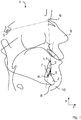
- the illustration shown is derived from a cephalometric side image. However, such a representation can also be derived from a CT or DVT recording.
- the illustration shown is a two-dimensional schematic representation of the anterior part of a laterolateral image of the head 1, showing in particular the patient's jaw, including lower jawbone 2 and an incisor 3.
- the incisor 3 has a tooth crown 4, which is coated with enamel, and a tooth root 5 (see Fig. 2 ). Between the tooth crown 4 and the tooth root 5, the enamel border 6 is formed.
- the lower jaw bone 2 has the alveolar process 7, which carries the incisor 4, and the lower jaw base 8, which faces away from the incisor 3.
- the nose 9 and the chin 10 of the patient can be seen.
- Fig. 1 are known from the prior art, conventional reference points and the reference points used in the invention are shown.
- the conventional lines known from the prior art between conventional reference points are in Fig. 1 marked by dash-dot lines.
- the two straight lines of the inventively provided angle aL1-CEJ2-B are in the FIGS. 1 and 2 shown as solid lines.
- Table 2 reference point definition S Sella - center of the bony crypts of the Sella turcica: It represents a constructed point, which lies in the median Sagittal level.
- N Nasion - Nasion is the anteriostic point of the naso-frontal suture. If the suture moves forward into an open V-shape, the posterior point of the V is used. The point lies in the median-sagittal plane.
- aL1 Lower jaw incisor apex The most apical point of the root of the most anterior mid mandibular central incisor B B point: the lowest point of the anterior contour of the mandibular alveolar process in the median-sagittal plane; Dorsal point on the curvature of the mandibular symphysis i L1 Point of the lower jaw incisor
- the angle SNB is an angle whose base is the reference point N, whose first leg is a straight line connecting the reference point N to the reference point S, and whose second leg connects the reference point N to the reference point B.
- the standard value of the angle SNB is 80.5 degrees [25].
- a straight line connects the reference point iL1 with the reference point aL1.
- the reference points used in the invention for determining the angle aL1-CEJ2-B are particularly in Fig. 2 to recognize.
- the fourth reference point CBJ2 is spaced on a vertical straight line v in the direction of the lower jaw base from the third reference point CBJ (see in particular FIG Fig. 3 ).
- the vertical straight line v is parallel to the vertical direction y of the recording.
- the third reference point CBJ with respect to the height direction y, the lowest point of the Enamel border 6 is.
- the third reference point is at the same time the closest point to the face.
- the angle aL1-CEJ2-B is fixed, the vertex of which is the fourth reference point CEJ2, whose first leg is a straight line connecting the fourth reference point CEJ2 to the first reference point aL1, and whose second leg is a It is even that connects the fourth reference point CEJ2 to the second reference point B (see also FIG Fig. 4 ).
- the angle aL1-CEJ2-B allows, in particular, a prognosis of the ideal lower anterior tooth incision.
- FIGS. 1 to 3 The illustrations shown are based on an image as derived from cephalograms, CT scans or CBCT scans. Although the depicted lower jaw form is anatomically variable for each individual subject, the reference points can be transferred or localized to all lower jaw forms.
Landscapes
- Health & Medical Sciences (AREA)
- Life Sciences & Earth Sciences (AREA)
- General Health & Medical Sciences (AREA)
- Oral & Maxillofacial Surgery (AREA)
- Dentistry (AREA)
- Epidemiology (AREA)
- Animal Behavior & Ethology (AREA)
- Public Health (AREA)
- Veterinary Medicine (AREA)
- Biomedical Technology (AREA)
- Biophysics (AREA)
- Engineering & Computer Science (AREA)
- Dental Tools And Instruments Or Auxiliary Dental Instruments (AREA)
Abstract
Description
- Die Erfindung betrifft ein Verfahren zur kephalometrischen Bestimmung einer Kenngröße eines Individuums. Sie betrifft auch die Verwendung eines Risikowertes zur Beurteilung des Risikos eines Zahnfleisch- und/oder Knochenschwundes an einem Schneidezahn eines Patienten. Sie betrifft außerdem ein Verfahren zur Beurteilung des Risikos eines Zahnfleisch- und/oder Knochenschwundes an einem Schneidezahn eines Patienten. Die erfindungsgemäßen Verfahren und die erfindungsgemäße Verwendung können insbesondere vor einer kieferorthopädischen und/oder parodontalen Therapie angewendet werden.
- Gingiva- und Knochenrezessionen sind inzwischen Probleme, die nicht nur bei erwachsenen Patienten, sondern auch immer häufiger bei Kindern zu sehen sind. Veränderungen im orofazialen Bereich sowie die Anpassung des Organismus an Pathomechanismen sind noch nicht vollständig bekannt. Wieso Rezessionen entstehen, hängt unter anderem vom Typ der Gingiva (dünn oder dick), aber auch in großem Umfang von der Zahnposition ab. Eine epidemiologische Langzeitstudie konnte zeigen, dass Gingivarezessionen in einer westeuropäischen Population mit regelmäßiger zahnärztlicher Kontrolle und zufriedenstellender Mundhygiene bei mehr als 60 % der jüngeren (bis zum 20. Lebensjahr) und bei mehr als 90 % der älteren ( > 50 Jahre) Personen vorlagen [1].
- Einen möglichen ätiologischen Faktor für die Entstehung von Rezessionen stellt unter anderem die kieferorthopädische Zahnbewegung dar. Besonders die Bewegung von Zähnen in Positionen außerhalb der labialen oder lingualen Oberfläche des Alveolarknochens könnte zur Entstehung von Dehiszenzen führen [2]. Es bestehen bis jetzt keine Verfahren zur Bestimmung der Schneidezahnposition und der gleichzeitigen Bestimmung des Knochenangebotes. Es ist allerdings umstritten, ob kieferorthopädische Zahnbewegungen tatsächlich Gingivarezessionen verursachen können oder ob sich Gingiva und Knochen an die neue Position der Zähne anpassen, wenn keine weiteren traumatisierenden Faktoren, wie etwa heftiges Putzen der Zähne, dazukommen. In der Literatur finden sich dazu widersprüchliche Aussagen [3].
- Zusammenfassend lässt sich sagen, dass bis jetzt keine Methode, um Rezessionen zu vermeiden oder vorzubeugen, gefunden wurde, die eine Vermessung des Knochenangebotes in Abhängigkeit von einem morphologischen Parameter, wie der Frontzahnposition, vorschlägt.
- Im Rahmen der Diagnostik des labiolingualen Knochenangebotes und der Knochenlamellen im Frontzahnbereich werden in der Kieferorthopädie am häufigsten Fernröntgenseitenbilder eingesetzt [4a, 4b]. Die meist computerunterstützte Messung erfolgt unter Verwendung von kommerziellen Programmen wie Dolphin Imaging & Management Solutions (CA, USA) und FRWin (Computer konkret AG, Deutschland). Da im unteren Frontzahnbereich am häufigsten Rezessionen, insbesondere nach einer kieferorthopädischen Therapie, aber auch altersbedingt auftreten, ist die Bestimmung der "idealen Unterkieferfrontzahnposition" von besonderem Interesse.
- Es sind bereits viele Vermessungsmethoden zur Bestimmung der unteren Frontzahnposition oder Bestimmung des anterioren Knochenangebotes in diesem Bereich bekannt. Sie basieren auf einer zweidimensionalen Vermessung eines Winkels zwischen der sogenannten NB-Linie und der unteren Frontzahnachse [5, 6, 7]. Die gesamte Diagnostik und die spätere kieferorthopädische Therapie (mit Hilfe der Multiband-Behandlung zur Verbesserung der Schneidezahnposition) beziehen sich dann auf die Senkrechte zur Okklusionsebene [8]. Die Varianz in den Abweichungen durch Wahl dieser Bezugslinie (Okkusionsebene) führt dann meist zu klinischen Problemen in Form von Rezessionen.
- Ein weiteres Verfahren stellt die Diagnostik anhand von Fotos oder die Einbindung von Fotos in Kombination mit Fernröntgenseitenbildern [9a, 9b] dar. Hierbei wurde festgestellt, dass eine reduzierte untere vordere Gesichtshöhe [10, 11, 12, 13, 14] sowie eine hohe Lippenschlusslinie [11, 13, 15, 16, 17] wahrscheinlich diejenigen Parameter sind, welche im Zusammenhang mit der Zahnposition am häufigsten erwähnt werden. Abgesehen davon ergaben viele Studien eine relativ große interindividuelle Variabilität bzw. widersprüchliche Ergebnisse in Bezug auf die meisten evaluierten kephalometrischen Parameter. Somit sind alle Verfahren, die keine direkte Zahnposition oder Knochendicke beurteilen, sehr unpräzise.
- Es wurden auch Hilfsapparaturen entwickelt, die eine Diagnostik der Schneidezahnposition direkt von der Zahnkrone ermöglichen sollten. Diese können an Zahnmodellen oder direkt im Mund erfolgen. Aber auch eine Anwendung von Hilfsapparaturen ermöglicht keine Korrelation zwischen Achsenstellung der Zähne und dem vorhandenen Knochenangebot. Die Vermessungsmethode der Zahnkrone hat keinen Bezug zum Knochen oder zur Gingiva [18, 19, 20].
- Die Computertomographie (CT) oder die digitale Volumentomographie (DVT) erlauben eine dreidimensionale Darstellung von Zahn und Knochen. Anhand der Darstellung der Strukturen ist eine gezielte Messung der Knochendicke sowie eine Bestimmung des Knochenverlustes nach der Behandlung möglich. Jetzige Verfahren ermöglichen allerdings keine Korrelation zur Zahnposition [21, 12, 23, 24]. Alleine durch die statische Bestimmung von Zahnposition und Knochendicke ist eine Prognose für eine Zahnbewegung nicht möglich.
- Obwohl das Endergebnis der Zahnposition große Auswirkungen auf den Alveolarknochen hat und eine Reihe von Krankheitssymptomen verursacht, war es nicht möglich, so eine Diagnostikmethode zu finden. Es gibt eine ganze Reihe von Verfahren, die sich allerdings entweder auf die Messung des vorhandenen Knochenangebotes oder die Zahnposition beziehen. Die heutigen Messmethoden und die Beziehung zwischen den Schneidezähnen und den knöchernen Strukturen oder anderen dentofazialen Parametern werden in der Literatur kontrovers diskutiert. Es gibt nur vage Aussagen zur Auswertungsmöglichkeit der Veränderung der Zahnposition. Dabei kann keiner der kommerziellen Computerprogramme eine Vermessung der Relation Zahn- zum Alveolarkochen vornehmen und somit keine Aussage zu der Wahrscheinlichkeit des Auftretens von Rezession bei Veränderung der Frontzahninklination im Rahmen der Behandlung liefern.
- Auch bei der Anwendung unterschiedlicher klinischer Verfahren zur Messung der Schneidezähne besteht kein Bezug zum Kieferknochen. Bei der Behandlung von Zahnschiefstand mittels MBT und Straight-Wire-Technik wird die Position der Schneidezähne auch nur zur Okklusionsebene festgelegt. Daher ist die Einstellung der gewünschten Schneidezahnposition während der Therapie häufig nur zufällig. Das aus
DE 199 157 428 A1 bekannte Verfahren benötigt sehr viele Messverfahren für eine OP-Planung und auch zur Bestimmung der Schneidezahnposition, aber es wird auch hier kein Bezug zu Knochen hergestellt. - Aufgabe der Erfindung ist es, die Nachteile nach dem Stand der Technik zu beseitigen. Es soll insbesondere ein Verfahren zur kephalometrischen Bestimmung einer Kenngröße eines Individuums angegeben werden, das eine zuverlässige Beurteilung des Risikos eines Zahnfleisch- und/oder Knochenschwundes an einem Schneidezahn eines Patienten ermöglicht. Es soll ferner die Verwendung eines Risikowertes zur Beurteilung des Risikos eines Zahnfleisch- und/oder Knochenschwundes an einem Schneidezahn eines Patienten angegeben werden. Außerdem soll ein Verfahren zur Beurteilung des Risikos eines Zahnfleisch- und/oder Knochenschwundes an einem Schneidezahn eines Patienten angegeben werden.
- Warmuz, J., et al., Oral health and dental management, 13 (3) 2014, 772-778, Dominiak, M., Gedrange, T., Advances in clinical and experimental medicine: official organ Wroclaw Medical University, 23 (6) 2014, 857-863, und Warmuz, J., et al., Annals of anatomy, Vol. 206, 64-72, offenbaren die Berechnung eines Winkels API-CEJ2-B, wobei der Bezugspunktes CEJ2 allerdings nicht auf einer vertikalen Geraden um einen Abstandswert versetzt angeordnet ist.
- Diese Aufgabe wird durch die Merkmale der Ansprüche 1, 7 und 11 gelöst. Zweckmäßige Ausgestaltungen der Erfindungen ergeben sich aus den Merkmalen der Unteransprüche.
- Nach Maßgabe der Erfindung ist ein Verfahren zur kephalometrischen Bestimmung einer Kenngröße eines Individuums vorgesehen, das das Bestimmen von Bezugspunkten in einer zwei- oder dreidimensionalen Aufnahme und das Bestimmen der Kenngröße aus den Bezugspunkten umfasst, wobei das Verfahren das
- Bestimmen eines ersten Bezugspunktes aL1, wobei der erste Bezugspunkt der Apex eines Schneidezahnes am Unterkiefer ist;
- Bestimmen eines zweiten Bezugspunktes B, wobei der zweite Bezugspunkt der B-Punkt ist;
- Bestimmen eines dritten Bezugspunktes CEJ, wobei der dritte Bezugspunkt auf der Zahnschmelzgrenze eines Schneidezahnes am Unterkiefer des Individuums liegt; und
- Bestimmen eines vierten Bezugspunktes CEJ2, der auf einer vertikalen Geraden, die durch den dritten Bezugspunkt CEJ verläuft, in Richtung der Unterkieferbasis um einen Abstandswert von dem dritten Bezugspunkt CEJ beabstandet ist, wobei der Abstandswert in einem Bereich von 1,3 mm bis 2,3 mm liegt;
- Die Erfindung ermöglicht durch eine Vermessung von Fernröntgenseitenbildern oder anderen zwei- oder dreidimensionalen Aufnahmen insbesondere eine Feststellung des anterioren Alveolarknochenangebotes. Eine solche Feststellung kann beispielsweise für eine Prognose der nach einer kieferorthopädischen oder parodontalen Therapie zu erwartenden Frontzahnendposition mit der in aller Wahrscheinlichkeit zur erwartenden parodontalen Rezession genutzt werden. Bei dem Individuum kann sich um einen Patienten handeln. Es ist allerdings nicht zwingend erforderlich, dass das Individuum, dessen Aufnahme zur Durchführung des erfindungsgemäßen Verfahrens eingesetzt wird, einer zahnärztlichen, insbesondere einer kieferorthopädischen oder parodontalen Therapie unterzogen wird, auch wenn das erfindungsgemäße Verfahren vorzugsweise zur Vorbereitung einer solchen Therapie eingesetzt werden kann. In diesem Fall erlaubt das erfindungsgemäße Verfahren eine Therapieprognose im Hinblick auf die Vermeidung der Entstehung einer Rezession.
- Das erfindungsgemäße Verfahren ermöglicht die Erstellung der Korrelation von direkt betroffenen dentalen und skelettalen Bezugspunkten. Dabei sind der erste Bezugspunkt aL1 und der dritte Bezugspunkt CEJ dentale Bezugspunkten, während der zweite Bezugspunkt B ein skelettaler Bezugspunkt ist. Der vierte Bezugspunkt CEJ2 ist ein von dem dritten Bezugspunkt abgeleiteter Bezugspunkt.
- Unter der Zahnschmelzgrenze (engl. cementoenamel junction) wird die am Zahn ausgebildete Grenze zwischen Zahnschmelz, der die Krone eines Zahns überzieht, und Zahngewebe, das die Wurzeln eines Zahns überzieht, verstanden. Erfindungsgemäß ist vorgesehen, dass der dritte Bezugspunkt CEJ auf der Zahnschmelzgrenze eines Schneidezahnes liegt. Dabei kann vorgesehen sein, dass der dritte Bezugspunkt CEJ der am tiefsten liegende Punkt und/oder der anteriorste Punkt der Zahnschmelzgrenze in der verwendeten Abbildung ist.
- Von den Erfindern durchgeführte, vertikale Messungen zur Festlegung des Punktes CEJ2 haben ergeben, dass die durchschnittliche Höhe einer Dehiszenz bei gesunden Probanden 1,8 ± 0,5 mm betrug. Es ist daher zweckmäßig, einen Abstandswert zwischen dem dritten Bezugspunkt CEJ und dem vierten Bezugspunkt CEJ2 vorzusehen, der in einem Bereich von 1,3 bis 2,3 mm liegt. Vorzugsweise beträgt der Abstandswert zwischen dem dritten Bezugspunkt CEJ und dem vierten Bezugspunkt CEJ2 2 mm. Alternativ kann jedoch vorgesehen sein, dass der Abstandswert in Abhängigkeit von der Tiefe des Sulkus, der den Schneidezahn umgibt, bestimmt wird.
- Die erfindungsgemäß eingesetzte zwei- oder dreidimensionale Aufnahme wird vorzugsweise mittels eines Röntgenverfahrens angefertigt. Beispielsweise kann es sich bei der zweidimensionalen Aufnahme um ein Fernröntgenseitenbild handeln. Die dreidimensionale Aufnahme kann mittels Computertomographie ("CT"), Magnetresonanztomographie, dentaler Volumentomographie ("DVT") oder anderer dreidimensionaler Aufnahmetechniken angefertigt werden. Vorzugsweise handelt es sich bei der zwei- oder dreidimensionalen Aufnahme um ein Fernröntgenseitenbild, eine dreidimensionale CT-Aufnahme oder eine dreidimensionale DVT-Aufnahme. Das Fernröntgenseitenbild zeigt vorzugsweise eine laterolaterale Aufnahme des Kopfes eines Individuums oder eines Teils des Kopfes, der den Kiefer umfasst.
- Die Erfindung ermöglicht eine Beurteilung des anterioren Knochenangebotes im unteren Alveolarfortsatzbereich und der unteren Frontzahnposition unter zu Hilfenahme des ersten, zweiten, dritten und vierten Bezugspunktes. Diese Bezugspunkte sind in der nachstehenden Tabelle 1 näher erläutert:
Tabelle 1 Bezugspunkt Definition aL1 Erster Bezugspunkt: Apex des Unterkiefer-Schneidezahnes: Der apikalste Punkt der Wurzel des am weitesten anterior stehenden mittleren Unterkiefer-Schneidezahnes B Zweiter Bezugspunkt: B-Punkt: tiefster Punkt der anterioren Kontur des Unterkiefer-Alvoelarfortsatzes in der Median-Sagittal-Ebene; dorsalster Punkt an der Kurvatur der Unterkiefersymphyse CEJ Dritter Bezugspunkt: Liegt auf der Zahnschmelzgrenze eines Schneidezahnes am Unterkiefer des Individuums, für den das Knochenangebot berechnet wird. CEJ2 Vierter Bezugspunkt: Liegt auf einer vertikalen Geraden, die durch den dritten Bezugspunkt CEJ verläuft, und ist in Richtung der Unterkieferbasis um einen Abstandswert von dem dritten Bezugspunkt CEJ beabstandet. Er dient für die Berechnung des Winkels. - Mittels der Bezugspunkte aL1, B, CEJ und CEJ2 kann ein Winkel aL1-CEJ2-B bestimmt werden, dessen Scheitelpunkt der vierte Bezugspunkt CEJ2 ist, dessen erster Schenkel eine Gerade ist, die den vierten Bezugspunkt CEJ2 mit dem ersten Bezugspunkt aL1 verbindet, und dessen zweiter Schenkel eine Gerade ist, die den vierten Bezugspunkt CEJ2 mit dem zweiten Bezugspunkt B verbindet. Der erste, zweite, dritte und vierte Bezugspunkt liegen vorzugsweise in einer Ebene der zwei- oder dreidimensionalen Aufnahme.
- Die Verknüpfung der beiden Eigenschaften "anteriores Knochenangebot im unteren Alveolarfortsatzbereich" und "untere Frontzahnposition" ermöglichen eine Prognose der Zahnbewegung. Eine solche Prognose ist vor allem nützlich, um die Wahrscheinlichkeit einer Entwicklung von parodontalen Rezessionen zu bewerten. Das erfindungsgemäße Verfahren ermöglicht eine Auswertung der Knochen auf der labialen Seite des Unterkiefers.
- Nach Maßgabe der Erfindung ist ferner die Verwendung des Winkels aL1-CEJ2-B zur Beurteilung des Risikos eines Zahnfleisch- und/oder Knochenschwundes an einem Schneidezahn eines Patienten vorgesehen. Das Risiko eines Zahnfleisch- und/oder Knochenschwundes besteht, wenn der Winkel aL1-CEJ2-B einen Wert besitzt, der unterhalb eines Risikowertes liegt. Die Erfinder haben festgestellt, dass ein Risikowert von 16° für die Beurteilung des Risikos vorteilhaft ist.
- Der Winkel aL1-CEJ2-B kann dabei mittels des erfindungsgemäßen Verfahrens bestimmt werden. Das heißt mit anderen Worten, dass der Risikowert auf Grundlage der kephalometrischen Vermessung einer zwei- oder dreidimensionalen Aufnahme unter Verwendung des ersten, zweiten, dritten und vierten Bezugspunktes bestimmt wird. Der Risikowert ist der sogenannte kritische Wert der Breite des Knochens im vorderen Bereich des Unterkiefers. Die Erfinder haben festgestellt, dass es vorteilhaft ist, einen kritischen Wert von 16° zur Beurteilung des Risikos zu verwenden. Unterhalb dieses kritischen Wertes erhöht sich das Risiko von Zahnfleisch- und/oder Knochenschwund deutlich.
- Nach Maßgabe der Erfindung ist außerdem ein Verfahren zur Beurteilung des Risikos eines Zahnfleisch- und/oder Knochenschwundes an einem Schneidezahn eines Patienten vorgesehen, dass die Schritte umfasst:
- (a) Bereitstellen einer zwei- oder dreidimensionalen Aufnahme des Kopfes des Patienten oder eines Teils des Kopfes, der den Kiefer des Patienten umfasst;
- (b) Bestimmen von Bezugspunkten in der zwei- oder dreidimensionalen Aufnahme, umfassend das
- Bestimmen eines ersten Bezugspunktes aL1, wobei der erste Bezugspunkt der Apex des Schneidezahnes am Unterkiefer ist;
- Bestimmen eines zweiten Bezugspunktes B, wobei der zweite Bezugspunkt der B-Punkt ist;
- Bestimmen eines dritten Bezugspunktes CEJ, wobei der dritte Bezugspunkt auf der Zahnschmelzgrenze des Schneidezahnes am Unterkiefer des Patienten liegt; und
- Bestimmen eines vierten Bezugspunktes CEJ2, der auf einer vertikalen Geraden, die durch den dritten Bezugspunkt CEJ verläuft, in Richtung der Unterkieferbasis um einen Abstandswert von dem dritten Bezugspunkt CEJ beabstandet ist, wobei der Abstandswert in einem Bereich von 1,3 mm bis 2,3 mm liegt;
- (c) Bestimmen aus dem ersten Bezugspunkt aL1, dem zweiten Bezugspunkt B und dem vierten Bezugspunkt CEJ2 eines Winkels in der zwei- oder dreidimensionalen Aufnahme, dessen Scheitelpunkt der vierte Bezugspunkt CEJ2 ist, dessen erster Schenkel eine Gerade ist, die den vierten Bezugspunkt CEJ2 mit dem ersten Bezugspunkt aL1 verbindet, und dessen zweiter Schenkel eine Gerade ist, die den vierten Bezugspunkt CEJ2 mit dem zweiten Bezugspunkt B verbindet; und
- (d) Beurteilung des Risikos eines Zahnfleisch- und/oder Knochenschwundes an dem Schneidezahn des Patienten unter Verwendung des Winkels aL1-CEJ2-B als Risikowert, wobei das Risiko eines Zahnfleisch- und/oder Knochenschwundes besteht, wenn der Winkel aL1-CEJ2-B einen Wert besitzt, der unterhalb eines Risikowertes liegt.
- Dieses Vorfahren kann insbesondere vor einer kieferorthopädischen oder parodontalen Therapie durchgeführt werden. Weitere Einzelheiten dieses Verfahrens sind vorstehend im Zusammenhang mit dem erfindungsgemäßen Verfahren zur kephalometrischen Bestimmung einer Kenngröße eines Individuums und der erfindungsgemäßen Verwendung des Winkels aL1-CEJ2-B zur Beurteilung des Risikos eines Zahnfleisch- und/oder Knochenschwundes an einem Schneidezahn eines Patienten bereits erläutert worden.
- Durch die Verwendung des ersten, zweiten, dritten und vierten Bezugspunktes, die sowohl auf einem zweidimensionalen Fernröntgenseitenbild als auch auf einer dreidimensionalen CT- oder DVT-Aufnahme eindeutig zu lokalisieren sind und sich an dentalen und skelettalen Bezugspunkten orientieren, kann mit Hilfe des daraus generierten Winkels aL1-CEJ2-B eine Prognose über die individuell optimale untere Frontzahnposition getroffen werden. Damit kann die Entstehung von Rezessionen vermieden werden. Die Erfindung veranschaulicht, die Beziehung zwischen den dentalen und skelettalen Bezugspunkten.
- Bei der Retrusion von Schneidezähnen befindet sich der Drehpunkt in der Nähe der Zahnwurzelspitze. Die maximale Belastung befindet sich am lingualen Übergangspunkt zwischen Knochenrand und Zahn. Dies bewirkt, dass die Knochenresorption relativ rasch und bei geringer Belastung entsteht. Bei der reinen Protrusion der Schneidezähne befindet sich der Drehpunkt in der Nähe des Zahnhalses. Eine maximale Belastung ist dann im vierten Bezugspunkt CEJ2 zu erwarten. Somit träten hier bei gleicher Belastung wie bei der Retrusion seltener Rezessionen auf. Eine Protrusion mit Elongation von Schneidezähnen erhöht das Risiko von Rezessionen und eine Intrusion verringert sich.
- Die Erfindung bietet zahlreiche Vorteile. Sie kann die Planungssicherheit bei einer kieferorthopädischen Therapie erhöhen. Sie kann das Risiko der Entstehung von Rezessionen reduzieren. Sie kann in der Parodontaltherapie eingesetzt werden. Sie erlaubt die Vorhersage der anzuwendenden Biomechanik, d. h. Kraft, Richtung und Größe, einer zahnärztlich durchgeführten Drehung eines Zahnes.
- Die Erfindung wird nachstehend anhand von Ausführungsbeispielen, die die Erfindung nicht einschränken sollen, unter Bezugnahme auf die Zeichnungen näher erläutert. Dabei zeigen
- Fig. 1
- eine schematische Darstellung einer zweidimensionalen Aufnahme eines Teils des Kopfes eines Patienten;
- Fig. 2
- einen vergrößerten Ausschnitt von
Fig. 1 , der den Unterkiefer mit einem Schneidezahn zeigt; - Fig. 3
- einen vergrößerten Ausschnitt von
Fig. 2 , der einen Teil des Schneidezahnes mit der Zahnschmelzgrenze zeigt; und - Fig. 4
- eine Darstellung nur des Winkels aL1-CEJ2-B mit den in den
Figuren 2 und3 gezeigten Bezugspunkten. - Die in
Fig. 1 gezeigte Darstellung ist von einem Fernröntgenseitenbild abgeleitet. Eine derartige Darstellung kann aber auch von einer CT- oder DVT-Aufnahme abgeleitet werden. Die gezeigte Darstellung ist eine zweidimensionale schematische Wiedergabe des vorderen Teils einer laterolateralen Aufnahme des Kopfes 1, die insbesondere den Kiefer des Patienten, einschließlich Unterkieferknochen 2 und einen Schneidezahn 3, zeigt. Der Schneidezahn 3 weist eine Zahnkrone 4, die mit Zahnschmelz, überzogen ist, und eine Zahnwurzel 5 auf (sieheFig. 2 ). Zwischen der Zahnkrone 4 und der Zahnwurzel 5 ist die Zahnschmelzgrenze 6 ausgebildet. Der Unterkieferknochen 2 weist den Alveolarfortsatz 7, der den Schneidezahn 4 trägt, und die Unterkieferbasis 8 auf, die dem Schneidezahn 3 abgewandt ist. InFig. 1 sind ferner die Nase 9 und das Kinn 10 des Patienten zu erkennen. - In
Fig. 1 sind aus dem Stand der Technik bekannte, konventionelle Bezugspunkte sowie die erfindungsgemäß verwendeten Bezugspunkte eingezeichnet. Die aus dem Stand der Technik bekannten, konventionellen Linien zwischen konventionellen Bezugspunkten sind inFig. 1 durch Strich-Punkt-Linien gekennzeichnet. Die beiden Geraden des erfindungsgemäß vorgesehenen Winkels aL1-CEJ2-B sind in denFiguren 1 und2 als Volllinien gezeigt. - In
Fig. 1 sind die in Tabelle 2 erläuterten Bezugspunkte eingezeichnet:Tabelle 2 Bezugspunkt Definition S Sella - Zentrum der knöchernen Krypte der Sella turcica: Er stellt einen konstruierten Punkt dar, der in der Median-Sagittal-Ebene liegt. N Nasion - Das Nasion ist der anterioste Punkt der Sutura naso-frontalis. Geht die Sutur nach vorn in eine offene V-Form über, so wird der posterieste Punkt des V verwendet. Der Punkt liegt in der Median-Sagittal-Ebene. aL1 Apex des Unterkiefer-Schneidezahnes: Der apikalste Punkt der Wurzel des am weitesten anterior stehenden mittleren Unterkiefer-Schneidezahnes B B-Punkt: der tiefste Punkt der anterioren Kontur des Unterkiefer-Alvoelarfortsatzes in der Median-Sagittal-Ebene; dorsalster Punkt an der Kurvatur der Unterkiefersymphyse iL1 Spitze des Unterkiefer-Schneidezahnes - Der Winkel SNB ist ein Winkel, dessen Basis der Bezugspunkt N ist, dessen erster Schenkel eine Gerade ist, die den Bezugspunkt N mit dem Bezugspunkt S verbindet, und dessen zweiter Schenkel den Bezugspunkt N mit dem Bezugspunkt B verbindet. Der Normwert des Winkels SNB beträgt 80,5 Grad [25]. Eine Gerade verbindet den Bezugspunkt iL1 mit dem Bezugspunkt aL1.
- Die in der Erfindung genutzten Bezugspunkte zur Bestimmung des Winkels aL1-CEJ2-B sind insbesondere in
Fig. 2 zu erkennen. Dort sind der erste Bezugspunkt aL1, der zweite Bezugspunkt B, der dritte Bezugspunkt CBJ und der vierte Bezugspunkt CBJ2 eingezeichnet. Der vierte Bezugspunkt CBJ2 ist auf einer vertikalen Geraden v in Richtung der Unterkieferbasis von dem dritten Bezugspunkt CBJ beabstandet (siehe insbesondereFig. 3 ). Die vertikale Gerade v liegt parallel zur Höhenrichtung y der Aufnahme. Es ist ferner inFig. 3 zu erkennen, dass der dritte Bezugspunkt CBJ der, in Bezug auf die Höhenrichtung y, am tiefsten liegende Punkt der Zahnschmelzgrenze 6 ist. InFig. 3 ist der dritte Bezugspunkt gleichzeitig der dem Gesicht nächstliegende Punkt. - Mittels der Bezugspunkte aL1, CEJ2 und B ist der Winkel aL1-CEJ2-B festgelegt, dessen Scheitelpunkt der vierte Bezugspunkt CEJ2 ist, dessen erster Schenkel eine Gerade ist, die den vierten Bezugspunkt CEJ2 mit dem ersten Bezugspunkt aL1 verbindet, und dessen zweiter Schenkel eine Gerade ist, die den vierten Bezugspunkt CEJ2 mit dem zweiten Bezugspunkt B verbindet (siehe auch
Fig. 4 ). Der Winkel aL1-CEJ2-B ermöglicht insbesondere eine Prognose der idealen unteren Frontzahninklination. - Die in den
Figuren 1 bis 3 gezeigten Darstellungen beruhen auf einer Abbildung, wie sie sich von Fernröntgenseitenbildern, CT-Aufhahmen oder DVT-Aufnahmen ableiten lässt. Die abgebildete Unterkieferform ist zwar interindividuell anatomisch variabel, die Bezugspunkte lassen sich jedoch auf alle Unterkieferformen übertragen bzw. lokalisieren. -
- 1. Löe H, Anerud A, Boysen H. The natural history of periodontal disease in man: prevalence, severity, and extent of gingival recession. J Periodontol 1992; 63 (8): 489 -495.
- 2. Wennström J L, Lindhe J, Sinclair F et al. Some periodontal tissue reactions to orthodontic tooth movement in monkeys. J Clin Periodontol 1987; 14 (3): 121 - 129.
- 3. Joss-Vassalli I, Grabenstein C., Topouzelis N., Sculean A., Katsaros C. Kieferorthopädische Therapie und Gingivarezessionen: Inf Orthod Kieferorthop 2011; 43: 263-273.
- 4a.
US 5,318,441 A : Method Of Cephalometric Evaluation Of Dental Radiographs. - 4b.
US 8,805,048 B2 : Method system orthodontic diagnosis. - 5. Hasund A, Ulstein G. The position of the incisors in relation to the lines NA and NB in different facial types. Am J Orthod 1970; 57: 1-14.
- 6. Shudy FF. Cant of the occlusal plane and axial inclinations of teeth. Angle Orthod. 1963; 33: 69-82.
- 7. Steiner CC. The use of cephalometrics as an aid to planning and assessing orthodontic treatment. Am J Orthod 1960; 46: 721-35.
- 8. Andrews LF. Six keys to normal occlusion. Am J Orthod 1972; 62: 296-309.
- 9a.
US 6,200,278 B1 ; Gender Specific Soft Tissue Cephalometric Analysis For Diagnosis And Cephalometric Treatment Planning Of Facial Imbalance. - 9b.
US 5,951,498 A ; Soft tissue cephalometric analysis for diagnosis and cephalometric treatment planning of facial imbalance. - 10. Brezniak N, Arad A, Heller M, et al. Pathognomonic cephalometric characteristics of Angle Class II Division 2 malocclusion. Angle Orthod 2002; 72: 251-7.
- 11. Karlsen AT. Craniofacial characteristics in children with Angle Class II div. 2 malocclusion combined with extreme deep bite. Angle Orthod 1994; 64: 123-30.
- 12. Lux CJ, Raeth O, Burden D, et al. Sagittal and vertical growth of the jaws in Class II, Division 1 and Class II, Division 2 malocclusions during prepubertal and pubertal development. J Orofac Orthop 2004; 65: 290-311.
- 13. Mills JR. The problem of overbite in Class II, division 2 malocclusion. Br J Orthod 1973; 1: 34-48.
- 14. Pancherz H, Zieber K. Dentoskeletal morphology in children with Deckbiss. J Orofac Orthop 1998; 59: 274-85.
- 15. Devreese HO, Dermaut LR, De Pauw GAM. Upper incisor inclination and lip line: an orthodontic relationship? Eur J Orthod 2006; 28: e10-e11.
- 16. Fletcher GG. The retroclined upper incisor. Br J Orthod 1975; 2: 207-16.
- 17. Luffingham JK. The lower lip and the maxillary central incisor. Eur J Orthod 1982; 4: 263-8.
- 18.
US 6,945,779 B2 : Tooth Inclination Assessment. - 19. Knösel M, Attin R, Kubein-Meesenburg D, Sadat-Khonsari R. Cephalometric assessment of the axial inclination of upper and lower incisors in relation to the thirdorder angle. J Orofac Orthop. 2007 May; 68 (3): 199-209.
- 20. Miethke RR, Behm-Menthel A. Correlations between lower incisor crowding and lower incisor position and lateral craniofacial morphology. Am J Orthod Dentofacial Orthop. 1988 Sep; 94 (3): 231-9.
- 21. Nahm KY, Kang JH, Moon SC, Choi YS, Kook YA, Kim SH, Huang J. Alveolar bone loss around incisors in Class I bidentoalveolar protrusion patients: a retrospective three-dimensional cone beam CT study. Dentomaxillofac Radiol. 2012 Sep; 41 (6): 481-8.
- 22. Tian YL, Liu F, Sun HJ, Lv P, Cao YM, Yu M, Yue Y. Alveolar bone thickness around maxillary central incisors of different inclination assessed with cone-beam computed tomography. Korean J Orthod. 2015 Sep; 45 (5): 245-52.
- 23. Lee KM1, Kim YI, Park SB, Son WS. Alveolar bone loss around lower incisors during surgical orthodontic treatment in mandibular prognathism. Angle Orthod. 2012 Jul; 82 (4): 637-44.
- 24. Fuhrmann R. Three-dimensional interpretation of labiolingual bone width of the lower incisors. Part II. 1996 Jun; 57 (3): 168-85.
- 25. Segner D., Hasund A.: Individualisierte Kephalometrie. 2. Auflage. Dietmar Segner Verlag, Hamburg 1994.
-
- 1
- Kopf
- 2
- Unterkieferknochen
- 3
- Schneidezahn
- 4
- Zahnkrone
- 5
- Zahnwurzel
- 6
- Zahnschmelzgrenze
- 7
- Alveolarfortsatz
- 8
- Unterkieferbasis
- 9
- Nase
- 10
- Kinn
Claims (15)
- Verfahren zur kephalometrischen Bestimmung einer Kenngröße eines Individuums, umfassend das Bestimmen von Bezugspunkten in einer zwei- oder dreidimensionalen Aufnahme und das Bestimmen der Kenngröße aus den Bezugspunkten, wobei das Verfahren das- Bestimmen eines ersten Bezugspunktes aL1, wobei der erste Bezugspunkt der Apex eines Schneidezahnes (3) am Unterkiefer ist;- Bestimmen eines zweiten Bezugspunktes B, wobei der zweite Bezugspunkt der B-Punkt ist;- Bestimmen eines dritten Bezugspunktes CEJ, wobei der dritte Bezugspunkt auf der Zahnschmelzgrenze (6) des Schneidezahnes (3) am Unterkiefer des Individuums liegt; und- Bestimmen eines vierten Bezugspunktes CEJ2, der auf einer vertikalen Geraden (v), die durch den dritten Bezugspunkt CEJ verläuft, in Richtung der Unterkieferbasis (8) um einen Abstandswert (a) von dem dritten Bezugspunkt CEJ beabstandet ist, wobei der Abstandswert (a) in einem Bereich von 1,3 mm bis 2,3 mm liegt;umfasst und aus dem ersten Bezugspunkt aL1, dem zweiten Bezugspunkt B und dem vierten Bezugspunkt CEJ2 ein als individuelle Kenngröße dienender Winkel aL1-CEJ2-B bestimmt wird, dessen Scheitelpunkt der vierte Bezugspunkt CEJ2 ist, dessen erster Schenkel eine Gerade ist, die den vierten Bezugspunkt CEJ2 mit dem ersten Bezugspunkt aL1 verbindet, und dessen zweiter Schenkel eine Gerade ist, die den vierten Bezugspunkt CEJ2 mit dem zweiten Bezugspunkt B verbindet.
- Verfahren nach Anspruch 1, dadurch gekennzeichnet, dass der Abstandswert (a) 2 mm beträgt.
- Verfahren nach Anspruch 1 oder Anspruch 2, dadurch gekennzeichnet, dass der Abstandswert (a) in Abhängigkeit von der Tiefe des Sulkus, der den Schneidezahn (3) umgibt, bestimmt wird.
- Verfahren nach einem der vorstehenden Ansprüche, dadurch gekennzeichnet, dass die zwei- oder dreidimensionale Aufnahme mittels eines Röntgenverfahrens angefertigt wird.
- Verfahren nach einem der vorstehenden Ansprüche, dadurch gekennzeichnet, dass die zwei- oder dreidimensionale Aufnahme ein Fernröntgenseitenbild ist.
- Verfahren nach einem der vorstehenden Ansprüche, dadurch gekennzeichnet, dass die zwei- oder dreidimensionale Aufnahme mittels Computertomographie, Magnetresonanztomographie, dentaler Volumentomographie oder anderer 3D-Aufnahmetechniken angefertigt wird.
- Verwendung eines Winkels aL1-CEJ2-B zur Beurteilung des Risikos eines Zahnfleisch- und/oder Knochenschwundes an einem Schneidezahn (3) eines Patienten, wobei das Risiko besteht, wenn der Winkel aL1-CEJ2-B einen Wert besitzt, der unterhalb eines Risikowertes liegt, aL1, B und CEJ2 Bezugspunkte in einer zwei- oder dreidimensionalen Aufnahme sind und- aL1 ein erster Bezugspunkt ist, der der Apex des Schneidezahnes (3) am Unterkiefer ist;- B ein zweiter Bezugspunkt ist, der der B-Punkt ist; und- CEJ2 ein vierter Bezugspunkt ist, der auf einer vertikalen Geraden, die durch einen dritten Bezugspunkt CEJ in der zwei- oder dreidimensionalen Aufnahme verläuft, in Richtung der Unterkieferbasis (8) um einen Abstandswert von dem dritten Bezugspunkt CEJ beabstandet ist, wobei der dritte Bezugspunkt CEJ auf der die Zahnschmelzgrenze (6) des Schneidezahnes (3) am Unterkiefer des Patienten liegt und wobei der Abstandswert in einem Bereich von 1,3 mm bis 2,3 mm liegt;wobei der Scheitelpunkt des Winkels aL1-CEJ2-B der vierte Bezugspunkt CEJ2 ist, der erster Schenkel des Winkels aL1-CEJ2-B eine Gerade ist, die den vierten Bezugspunkt CEJ2 mit dem ersten Bezugspunkt aL1 verbindet, und der zweite Schenkel eine Gerade ist, die den vierten Bezugspunkt CEJ2 mit dem zweiten Bezugspunkt B verbindet.
- Verwendung nach Anspruch 7, dadurch gekennzeichnet, dass der Abstandswert (a) 2 mm beträgt.
- Verwendung nach Anspruch 7 oder Anspruch 8, dadurch gekennzeichnet, dass der Abstandswert (a) in Abhängigkeit von der Tiefe des Sulkus, der den Schneidezahn (3) umgibt, bestimmt ist.
- Verwendung nach einem der Ansprüche 7 bis 9, dadurch gekennzeichnet, dass der Risikowert 16° ist.
- Verfahren zur Beurteilung des Risikos eines Zahnfleisch- und/oder Knochenschwundes an einem Schneidezahn (3) eines Patienten, dadurch gekennzeichnet, dass es die Schritte umfasst:(a) Bereitstellen einer zwei- oder dreidimensionalen Aufnahme des Kopfes (1) des Patienten oder eines Teils des Kopfes (1), der den Kiefer des Patienten umfasst;(b) Bestimmen von Bezugspunkten in der zwei- oder dreidimensionalen Aufnahme, umfassend das- Bestimmen eines ersten Bezugspunktes aL1, wobei der erste Bezugspunkt der Apex des Schneidezahnes (3) am Unterkiefer ist;- Bestimmen eines zweiten Bezugspunktes B, wobei der zweite Bezugspunkt der B-Punkt ist;- Bestimmen eines dritten Bezugspunktes CEJ, wobei der dritte Bezugspunkt auf der Zahnschmelzgrenze (6) des Schneidezahnes am Unterkiefer des Patienten liegt; und- Bestimmen eines viertes Bezugspunktes CEJ2, der auf einer vertikalen Geraden, die durch den dritten Bezugspunkt CEJ verläuft, in Richtung der Unterkieferbasis (8) um einen Abstandswert (a) von dem dritten Bezugspunkt CEJ beabstandet ist, wobei der Abstandswert in einem Bereich von 1,3 mm bis 2,3 mm liegt;(c) Bestimmen aus dem ersten Bezugspunkt aL1, dem zweiten Bezugspunkt B und dem vierten Bezugspunkt CEJ2 eines Winkels in der zwei- oder dreidimensionalen Aufnahme, dessen Scheitelpunkt der vierte Bezugspunkt CEJ2 ist, dessen erster Schenkel eine Gerade ist, die den vierten Bezugspunkt CEJ2 mit dem ersten Bezugspunkt aL1 verbindet, und dessen zweiter Schenkel eine Gerade ist, die den vierten Bezugspunkt CEJ2 mit dem zweiten Bezugspunkt B verbindet; und(d) Beurteilung des Risikos eines Zahnfleisch- und/oder Knochenschwundes an dem Schneidezahn (3) des Patienten unter Verwendung des Winkels aL1-CEJ2-B als Risikowert, wobei das Risiko eines Zahnfleisch- und/oder Knochenschwundes besteht, wenn der Winkel aL1-CEJ2-B einen Wert besitzt, der unterhalb eines Risikowertes liegt.
- Verfahren nach Anspruch 11, dadurch gekennzeichnet, dass der Abstandswert (a) 2 mm beträgt.
- Verfahren nach Anspruch 11 oder Anspruch 12, dadurch gekennzeichnet, dass der Abstandswert (a) in Abhängigkeit von der Tiefe des Sulkus, der den Schneidezahn umgibt, bestimmt ist.
- Verfahren nach einem der Ansprüche 11 bis 13, dadurch gekennzeichnet, dass der Risikowert 16° ist.
- Verfahren nach einem der Ansprüche 11 bis 14, dadurch gekennzeichnet, dass es vor einer kieferorthopädischen oder parodontalen Therapie durchgeführt wird.
Applications Claiming Priority (1)
| Application Number | Priority Date | Filing Date | Title |
|---|---|---|---|
| DE102016115092.4A DE102016115092B4 (de) | 2016-08-15 | 2016-08-15 | Verwendung einer Kenngröße eines Individuums zur Beurteilung des Risikos eines Zahnfleisch- und/oder Knochenschwundes an einem Schneidezahn |
Publications (2)
| Publication Number | Publication Date |
|---|---|
| EP3287097A1 true EP3287097A1 (de) | 2018-02-28 |
| EP3287097B1 EP3287097B1 (de) | 2019-04-10 |
Family
ID=59626527
Family Applications (1)
| Application Number | Title | Priority Date | Filing Date |
|---|---|---|---|
| EP17186204.8A Active EP3287097B1 (de) | 2016-08-15 | 2017-08-14 | Verfahren zur kephalometrischen bestimmung einer kenngrösse eines individuums |
Country Status (2)
| Country | Link |
|---|---|
| EP (1) | EP3287097B1 (de) |
| DE (1) | DE102016115092B4 (de) |
Cited By (1)
| Publication number | Priority date | Publication date | Assignee | Title |
|---|---|---|---|---|
| CN119856943A (zh) * | 2024-12-25 | 2025-04-22 | 四川大学 | 基于三维重建的根尖点到牙槽突颊腭侧骨板距离测量方法 |
Family Cites Families (6)
| Publication number | Priority date | Publication date | Assignee | Title |
|---|---|---|---|---|
| US5318441A (en) | 1992-09-17 | 1994-06-07 | Keller Duane C | Method of cephalometric evaluation of dental radiographs |
| US5951498A (en) | 1997-10-16 | 1999-09-14 | Arnett Facial Reconstruction Courses, Inc. | Soft tissue cephalometric analysis for diagnosis and cephalometric treatment planning of facial imbalance |
| US6200278B1 (en) | 1997-10-16 | 2001-03-13 | Arnett Facial Reconstruction Courses, Inc. | Gender specific soft tissue cephalometric analysis for diagnosis and cephalometric treatment planning of facial imbalance |
| DE19957428A1 (de) | 1999-11-30 | 2001-05-31 | Dirk Vollmer | Orthognather Chirurgieplaner |
| GB0005053D0 (en) | 2000-03-03 | 2000-04-26 | Univ Wales Medicine | Tooth inclination assessment |
| US8805048B2 (en) | 2010-04-01 | 2014-08-12 | Mark Batesole | Method and system for orthodontic diagnosis |
-
2016
- 2016-08-15 DE DE102016115092.4A patent/DE102016115092B4/de active Active
-
2017
- 2017-08-14 EP EP17186204.8A patent/EP3287097B1/de active Active
Non-Patent Citations (3)
| Title |
|---|
| JUSTYNA WARMUZ ET AL: "Practical Application of a Method for Assessing the Progression of Gingival Recessions in Orthodontically Treated Patients - A Pilot Study", OHDM - VOL. 13 - NO. 3, September 2014 (2014-09-01), XP055437179, Retrieved from the Internet <URL:https://www.researchgate.net/profile/Marzena_Dominiak/publication/266626885_Practical_application_of_a_method_for_assessing_the_progression_of_gingival_recessions_in_orthodontically_treated_patients--a_pilot_study/links/578e958508aecbca4caad3c0.pdf> [retrieved on 20171221] * |
| MARZENA DOMINIAK ET AL: "New Perspectives in the Diagnostic of Gingival Recession", ADVANCES IN CLINICAL AND EXPERIMENTAL MEDICINE, vol. 23, no. 6, January 2014 (2014-01-01), PL, pages 857 - 863, XP055437167, ISSN: 1899-5276, DOI: 10.17219/acem/27907 * |
| WARMUZ JUSTYNA ET AL: "Influence of morphological parameters on the development of gingival recession in class III malocclusion", ANNALS OF ANATOMY, JENA, DE, vol. 206, 7 June 2015 (2015-06-07), pages 64 - 72, XP029581973, ISSN: 0940-9602, DOI: 10.1016/J.AANAT.2015.04.008 * |
Cited By (1)
| Publication number | Priority date | Publication date | Assignee | Title |
|---|---|---|---|---|
| CN119856943A (zh) * | 2024-12-25 | 2025-04-22 | 四川大学 | 基于三维重建的根尖点到牙槽突颊腭侧骨板距离测量方法 |
Also Published As
| Publication number | Publication date |
|---|---|
| EP3287097B1 (de) | 2019-04-10 |
| DE102016115092B4 (de) | 2018-03-01 |
| DE102016115092A1 (de) | 2018-02-15 |
Similar Documents
| Publication | Publication Date | Title |
|---|---|---|
| Jivraj et al. | Treatment planning of implants in the aesthetic zone | |
| Ngeow et al. | The location of the mental foramen in a selected Malay population | |
| DE60308701T2 (de) | Verfahren zur bestimmung der grossen achse eines objekts | |
| Raber et al. | Three-dimensional evaluation of labial alveolar bone overlying the maxillary and mandibular incisors in different skeletal classifications of malocclusion | |
| Bueno et al. | Root canal shape of human permanent teeth determined by new cone-beam computed tomographic software | |
| Veli et al. | Buccal cortical bone thickness at miniscrew placement sites in patients with different vertical skeletal patterns | |
| Chen et al. | CAD-CAM titanium preparation template for the socket-shield technique | |
| El-Dawlatly et al. | Zygomatic mini-implant for Class II correction in growing patients | |
| Reukers et al. | Radiographic evaluation of apical root resorption with 2 different types of edgewise appliances: results of a randomized clinical trial | |
| Tamimi et al. | Cone beam computed tomography in the assessment of dental impactions | |
| Chang et al. | Factors affecting external apical root resorption of maxillary incisors associated with microimplant-assisted rapid palatal expansion | |
| EP3287097B1 (de) | Verfahren zur kephalometrischen bestimmung einer kenngrösse eines individuums | |
| DE112005001198B4 (de) | Dentalmessinstrumente | |
| Präger et al. | Investigation of bone conditions for orthodontic anchorage plates in the anterior mandible | |
| Freisfeld et al. | Assessment of the space for the lower wisdom teeth: Panoramic radiography in comparison with computed tomography | |
| Präger et al. | Assessing bone volume for orthodontic miniplate fixation below the maxillary frontal process | |
| Linjawi | Comparison between characteristics of maxillary right and left central incisors: A cone-beam computed tomography study | |
| Kabak et al. | Imaging of accessory buccal foramina using cone-beam computed tomography | |
| Hermanson et al. | Utilization of cone beam computed tomography in analyzing the relationship between the mandibular fourth premolar tooth roots, the mandibular canal, and ventral mandibular cortex in 81 small breed dogs | |
| Shahi et al. | A rare case of three single rooted permanent second molars: A diagnosis with cone beam computed tomography (CBCT) | |
| Rodrigues et al. | Iatrogenics in dentistry: importance of radiographic examinations in identifying dental treatment failures, study by use trough the analysis of panoramic radiographs | |
| Ahmed et al. | Assessment of anterior maxillary alveolar bone dimensions and morphology for immediate implant planning: A retrospective study using Planmeca Promax CBCT unit | |
| Boteva et al. | Frequency of iatrogenic changes caused from overhang restorations | |
| Ermel et al. | Long-term stability of treatment results after upper jaw segmented osteotomy according to Schuchardt for correction of anterior open bite | |
| Goncalves et al. | Evaluation of dental implants using computed tomography |
Legal Events
| Date | Code | Title | Description |
|---|---|---|---|
| PUAI | Public reference made under article 153(3) epc to a published international application that has entered the european phase |
Free format text: ORIGINAL CODE: 0009012 |
|
| STAA | Information on the status of an ep patent application or granted ep patent |
Free format text: STATUS: THE APPLICATION HAS BEEN PUBLISHED |
|
| AK | Designated contracting states |
Kind code of ref document: A1 Designated state(s): AL AT BE BG CH CY CZ DE DK EE ES FI FR GB GR HR HU IE IS IT LI LT LU LV MC MK MT NL NO PL PT RO RS SE SI SK SM TR |
|
| AX | Request for extension of the european patent |
Extension state: BA ME |
|
| STAA | Information on the status of an ep patent application or granted ep patent |
Free format text: STATUS: REQUEST FOR EXAMINATION WAS MADE |
|
| 17P | Request for examination filed |
Effective date: 20180827 |
|
| RBV | Designated contracting states (corrected) |
Designated state(s): AL AT BE BG CH CY CZ DE DK EE ES FI FR GB GR HR HU IE IS IT LI LT LU LV MC MK MT NL NO PL PT RO RS SE SI SK SM TR |
|
| GRAP | Despatch of communication of intention to grant a patent |
Free format text: ORIGINAL CODE: EPIDOSNIGR1 |
|
| STAA | Information on the status of an ep patent application or granted ep patent |
Free format text: STATUS: GRANT OF PATENT IS INTENDED |
|
| INTG | Intention to grant announced |
Effective date: 20181030 |
|
| GRAS | Grant fee paid |
Free format text: ORIGINAL CODE: EPIDOSNIGR3 |
|
| GRAA | (expected) grant |
Free format text: ORIGINAL CODE: 0009210 |
|
| STAA | Information on the status of an ep patent application or granted ep patent |
Free format text: STATUS: THE PATENT HAS BEEN GRANTED |
|
| AK | Designated contracting states |
Kind code of ref document: B1 Designated state(s): AL AT BE BG CH CY CZ DE DK EE ES FI FR GB GR HR HU IE IS IT LI LT LU LV MC MK MT NL NO PL PT RO RS SE SI SK SM TR |
|
| REG | Reference to a national code |
Ref country code: GB Ref legal event code: FG4D Free format text: NOT ENGLISH |
|
| REG | Reference to a national code |
Ref country code: AT Ref legal event code: REF Ref document number: 1117660 Country of ref document: AT Kind code of ref document: T Effective date: 20190415 Ref country code: CH Ref legal event code: EP |
|
| REG | Reference to a national code |
Ref country code: IE Ref legal event code: FG4D Free format text: LANGUAGE OF EP DOCUMENT: GERMAN |
|
| REG | Reference to a national code |
Ref country code: DE Ref legal event code: R096 Ref document number: 502017001088 Country of ref document: DE |
|
| REG | Reference to a national code |
Ref country code: NL Ref legal event code: FP |
|
| REG | Reference to a national code |
Ref country code: SE Ref legal event code: TRGR |
|
| REG | Reference to a national code |
Ref country code: LT Ref legal event code: MG4D |
|
| PG25 | Lapsed in a contracting state [announced via postgrant information from national office to epo] |
Ref country code: HR Free format text: LAPSE BECAUSE OF FAILURE TO SUBMIT A TRANSLATION OF THE DESCRIPTION OR TO PAY THE FEE WITHIN THE PRESCRIBED TIME-LIMIT Effective date: 20190410 Ref country code: NO Free format text: LAPSE BECAUSE OF FAILURE TO SUBMIT A TRANSLATION OF THE DESCRIPTION OR TO PAY THE FEE WITHIN THE PRESCRIBED TIME-LIMIT Effective date: 20190710 Ref country code: PT Free format text: LAPSE BECAUSE OF FAILURE TO SUBMIT A TRANSLATION OF THE DESCRIPTION OR TO PAY THE FEE WITHIN THE PRESCRIBED TIME-LIMIT Effective date: 20190910 Ref country code: ES Free format text: LAPSE BECAUSE OF FAILURE TO SUBMIT A TRANSLATION OF THE DESCRIPTION OR TO PAY THE FEE WITHIN THE PRESCRIBED TIME-LIMIT Effective date: 20190410 Ref country code: AL Free format text: LAPSE BECAUSE OF FAILURE TO SUBMIT A TRANSLATION OF THE DESCRIPTION OR TO PAY THE FEE WITHIN THE PRESCRIBED TIME-LIMIT Effective date: 20190410 Ref country code: FI Free format text: LAPSE BECAUSE OF FAILURE TO SUBMIT A TRANSLATION OF THE DESCRIPTION OR TO PAY THE FEE WITHIN THE PRESCRIBED TIME-LIMIT Effective date: 20190410 Ref country code: LT Free format text: LAPSE BECAUSE OF FAILURE TO SUBMIT A TRANSLATION OF THE DESCRIPTION OR TO PAY THE FEE WITHIN THE PRESCRIBED TIME-LIMIT Effective date: 20190410 |
|
| PG25 | Lapsed in a contracting state [announced via postgrant information from national office to epo] |
Ref country code: RS Free format text: LAPSE BECAUSE OF FAILURE TO SUBMIT A TRANSLATION OF THE DESCRIPTION OR TO PAY THE FEE WITHIN THE PRESCRIBED TIME-LIMIT Effective date: 20190410 Ref country code: LV Free format text: LAPSE BECAUSE OF FAILURE TO SUBMIT A TRANSLATION OF THE DESCRIPTION OR TO PAY THE FEE WITHIN THE PRESCRIBED TIME-LIMIT Effective date: 20190410 Ref country code: PL Free format text: LAPSE BECAUSE OF FAILURE TO SUBMIT A TRANSLATION OF THE DESCRIPTION OR TO PAY THE FEE WITHIN THE PRESCRIBED TIME-LIMIT Effective date: 20190410 Ref country code: BG Free format text: LAPSE BECAUSE OF FAILURE TO SUBMIT A TRANSLATION OF THE DESCRIPTION OR TO PAY THE FEE WITHIN THE PRESCRIBED TIME-LIMIT Effective date: 20190710 Ref country code: GR Free format text: LAPSE BECAUSE OF FAILURE TO SUBMIT A TRANSLATION OF THE DESCRIPTION OR TO PAY THE FEE WITHIN THE PRESCRIBED TIME-LIMIT Effective date: 20190711 |
|
| PG25 | Lapsed in a contracting state [announced via postgrant information from national office to epo] |
Ref country code: IS Free format text: LAPSE BECAUSE OF FAILURE TO SUBMIT A TRANSLATION OF THE DESCRIPTION OR TO PAY THE FEE WITHIN THE PRESCRIBED TIME-LIMIT Effective date: 20190810 |
|
| REG | Reference to a national code |
Ref country code: DE Ref legal event code: R097 Ref document number: 502017001088 Country of ref document: DE |
|
| PG25 | Lapsed in a contracting state [announced via postgrant information from national office to epo] |
Ref country code: SK Free format text: LAPSE BECAUSE OF FAILURE TO SUBMIT A TRANSLATION OF THE DESCRIPTION OR TO PAY THE FEE WITHIN THE PRESCRIBED TIME-LIMIT Effective date: 20190410 Ref country code: CZ Free format text: LAPSE BECAUSE OF FAILURE TO SUBMIT A TRANSLATION OF THE DESCRIPTION OR TO PAY THE FEE WITHIN THE PRESCRIBED TIME-LIMIT Effective date: 20190410 Ref country code: RO Free format text: LAPSE BECAUSE OF FAILURE TO SUBMIT A TRANSLATION OF THE DESCRIPTION OR TO PAY THE FEE WITHIN THE PRESCRIBED TIME-LIMIT Effective date: 20190410 Ref country code: DK Free format text: LAPSE BECAUSE OF FAILURE TO SUBMIT A TRANSLATION OF THE DESCRIPTION OR TO PAY THE FEE WITHIN THE PRESCRIBED TIME-LIMIT Effective date: 20190410 Ref country code: EE Free format text: LAPSE BECAUSE OF FAILURE TO SUBMIT A TRANSLATION OF THE DESCRIPTION OR TO PAY THE FEE WITHIN THE PRESCRIBED TIME-LIMIT Effective date: 20190410 |
|
| PLBE | No opposition filed within time limit |
Free format text: ORIGINAL CODE: 0009261 |
|
| STAA | Information on the status of an ep patent application or granted ep patent |
Free format text: STATUS: NO OPPOSITION FILED WITHIN TIME LIMIT |
|
| PG25 | Lapsed in a contracting state [announced via postgrant information from national office to epo] |
Ref country code: SM Free format text: LAPSE BECAUSE OF FAILURE TO SUBMIT A TRANSLATION OF THE DESCRIPTION OR TO PAY THE FEE WITHIN THE PRESCRIBED TIME-LIMIT Effective date: 20190410 Ref country code: IT Free format text: LAPSE BECAUSE OF FAILURE TO SUBMIT A TRANSLATION OF THE DESCRIPTION OR TO PAY THE FEE WITHIN THE PRESCRIBED TIME-LIMIT Effective date: 20190410 |
|
| 26N | No opposition filed |
Effective date: 20200113 |
|
| PG25 | Lapsed in a contracting state [announced via postgrant information from national office to epo] |
Ref country code: TR Free format text: LAPSE BECAUSE OF FAILURE TO SUBMIT A TRANSLATION OF THE DESCRIPTION OR TO PAY THE FEE WITHIN THE PRESCRIBED TIME-LIMIT Effective date: 20190410 |
|
| PG25 | Lapsed in a contracting state [announced via postgrant information from national office to epo] |
Ref country code: SI Free format text: LAPSE BECAUSE OF FAILURE TO SUBMIT A TRANSLATION OF THE DESCRIPTION OR TO PAY THE FEE WITHIN THE PRESCRIBED TIME-LIMIT Effective date: 20190410 Ref country code: MC Free format text: LAPSE BECAUSE OF FAILURE TO SUBMIT A TRANSLATION OF THE DESCRIPTION OR TO PAY THE FEE WITHIN THE PRESCRIBED TIME-LIMIT Effective date: 20190410 Ref country code: LU Free format text: LAPSE BECAUSE OF NON-PAYMENT OF DUE FEES Effective date: 20190814 |
|
| PG25 | Lapsed in a contracting state [announced via postgrant information from national office to epo] |
Ref country code: IE Free format text: LAPSE BECAUSE OF NON-PAYMENT OF DUE FEES Effective date: 20190814 |
|
| PG25 | Lapsed in a contracting state [announced via postgrant information from national office to epo] |
Ref country code: CY Free format text: LAPSE BECAUSE OF FAILURE TO SUBMIT A TRANSLATION OF THE DESCRIPTION OR TO PAY THE FEE WITHIN THE PRESCRIBED TIME-LIMIT Effective date: 20190410 |
|
| PG25 | Lapsed in a contracting state [announced via postgrant information from national office to epo] |
Ref country code: MT Free format text: LAPSE BECAUSE OF FAILURE TO SUBMIT A TRANSLATION OF THE DESCRIPTION OR TO PAY THE FEE WITHIN THE PRESCRIBED TIME-LIMIT Effective date: 20190410 Ref country code: HU Free format text: LAPSE BECAUSE OF FAILURE TO SUBMIT A TRANSLATION OF THE DESCRIPTION OR TO PAY THE FEE WITHIN THE PRESCRIBED TIME-LIMIT; INVALID AB INITIO Effective date: 20170814 |
|
| PG25 | Lapsed in a contracting state [announced via postgrant information from national office to epo] |
Ref country code: MK Free format text: LAPSE BECAUSE OF FAILURE TO SUBMIT A TRANSLATION OF THE DESCRIPTION OR TO PAY THE FEE WITHIN THE PRESCRIBED TIME-LIMIT Effective date: 20190410 |
|
| P01 | Opt-out of the competence of the unified patent court (upc) registered |
Effective date: 20230524 |
|
| REG | Reference to a national code |
Ref country code: AT Ref legal event code: MM01 Ref document number: 1117660 Country of ref document: AT Kind code of ref document: T Effective date: 20220814 |
|
| PG25 | Lapsed in a contracting state [announced via postgrant information from national office to epo] |
Ref country code: AT Free format text: LAPSE BECAUSE OF NON-PAYMENT OF DUE FEES Effective date: 20220814 |
|
| PGFP | Annual fee paid to national office [announced via postgrant information from national office to epo] |
Ref country code: NL Payment date: 20250821 Year of fee payment: 9 |
|
| PGFP | Annual fee paid to national office [announced via postgrant information from national office to epo] |
Ref country code: DE Payment date: 20250813 Year of fee payment: 9 |
|
| PGFP | Annual fee paid to national office [announced via postgrant information from national office to epo] |
Ref country code: BE Payment date: 20250820 Year of fee payment: 9 Ref country code: GB Payment date: 20250822 Year of fee payment: 9 |
|
| PGFP | Annual fee paid to national office [announced via postgrant information from national office to epo] |
Ref country code: FR Payment date: 20250827 Year of fee payment: 9 |
|
| PGFP | Annual fee paid to national office [announced via postgrant information from national office to epo] |
Ref country code: CH Payment date: 20250901 Year of fee payment: 9 Ref country code: SE Payment date: 20250821 Year of fee payment: 9 |