EP3287084A1 - Energy treatment tool - Google Patents
Energy treatment tool Download PDFInfo
- Publication number
- EP3287084A1 EP3287084A1 EP16783046.2A EP16783046A EP3287084A1 EP 3287084 A1 EP3287084 A1 EP 3287084A1 EP 16783046 A EP16783046 A EP 16783046A EP 3287084 A1 EP3287084 A1 EP 3287084A1
- Authority
- EP
- European Patent Office
- Prior art keywords
- electric
- coil
- energy
- supplier
- longitudinal axis
- Prior art date
- Legal status (The legal status is an assumption and is not a legal conclusion. Google has not performed a legal analysis and makes no representation as to the accuracy of the status listed.)
- Withdrawn
Links
Images





Classifications
-
- A—HUMAN NECESSITIES
- A61—MEDICAL OR VETERINARY SCIENCE; HYGIENE
- A61B—DIAGNOSIS; SURGERY; IDENTIFICATION
- A61B18/00—Surgical instruments, devices or methods for transferring non-mechanical forms of energy to or from the body
- A61B18/04—Surgical instruments, devices or methods for transferring non-mechanical forms of energy to or from the body by heating
- A61B18/12—Surgical instruments, devices or methods for transferring non-mechanical forms of energy to or from the body by heating by passing a current through the tissue to be heated, e.g. high-frequency current
- A61B18/14—Probes or electrodes therefor
- A61B18/1482—Probes or electrodes therefor having a long rigid shaft for accessing the inner body transcutaneously in minimal invasive surgery, e.g. laparoscopy
-
- A—HUMAN NECESSITIES
- A61—MEDICAL OR VETERINARY SCIENCE; HYGIENE
- A61B—DIAGNOSIS; SURGERY; IDENTIFICATION
- A61B17/00—Surgical instruments, devices or methods
- A61B17/32—Surgical cutting instruments
- A61B17/320068—Surgical cutting instruments using mechanical vibrations, e.g. ultrasonic
-
- A—HUMAN NECESSITIES
- A61—MEDICAL OR VETERINARY SCIENCE; HYGIENE
- A61B—DIAGNOSIS; SURGERY; IDENTIFICATION
- A61B17/00—Surgical instruments, devices or methods
- A61B17/32—Surgical cutting instruments
- A61B17/320068—Surgical cutting instruments using mechanical vibrations, e.g. ultrasonic
- A61B17/320092—Surgical cutting instruments using mechanical vibrations, e.g. ultrasonic with additional movable means for clamping or cutting tissue, e.g. with a pivoting jaw
-
- A—HUMAN NECESSITIES
- A61—MEDICAL OR VETERINARY SCIENCE; HYGIENE
- A61B—DIAGNOSIS; SURGERY; IDENTIFICATION
- A61B18/00—Surgical instruments, devices or methods for transferring non-mechanical forms of energy to or from the body
- A61B18/04—Surgical instruments, devices or methods for transferring non-mechanical forms of energy to or from the body by heating
- A61B18/12—Surgical instruments, devices or methods for transferring non-mechanical forms of energy to or from the body by heating by passing a current through the tissue to be heated, e.g. high-frequency current
- A61B18/1206—Generators therefor
-
- A—HUMAN NECESSITIES
- A61—MEDICAL OR VETERINARY SCIENCE; HYGIENE
- A61B—DIAGNOSIS; SURGERY; IDENTIFICATION
- A61B18/00—Surgical instruments, devices or methods for transferring non-mechanical forms of energy to or from the body
- A61B18/04—Surgical instruments, devices or methods for transferring non-mechanical forms of energy to or from the body by heating
- A61B18/12—Surgical instruments, devices or methods for transferring non-mechanical forms of energy to or from the body by heating by passing a current through the tissue to be heated, e.g. high-frequency current
- A61B18/14—Probes or electrodes therefor
- A61B18/1442—Probes having pivoting end effectors, e.g. forceps
- A61B18/1445—Probes having pivoting end effectors, e.g. forceps at the distal end of a shaft, e.g. forceps or scissors at the end of a rigid rod
-
- A—HUMAN NECESSITIES
- A61—MEDICAL OR VETERINARY SCIENCE; HYGIENE
- A61B—DIAGNOSIS; SURGERY; IDENTIFICATION
- A61B17/00—Surgical instruments, devices or methods
- A61B2017/00367—Details of actuation of instruments, e.g. relations between pushing buttons, or the like, and activation of the tool, working tip, or the like
- A61B2017/00411—Details of actuation of instruments, e.g. relations between pushing buttons, or the like, and activation of the tool, working tip, or the like actuated by application of energy from an energy source outside the body
-
- A—HUMAN NECESSITIES
- A61—MEDICAL OR VETERINARY SCIENCE; HYGIENE
- A61B—DIAGNOSIS; SURGERY; IDENTIFICATION
- A61B17/00—Surgical instruments, devices or methods
- A61B17/32—Surgical cutting instruments
- A61B17/320068—Surgical cutting instruments using mechanical vibrations, e.g. ultrasonic
- A61B2017/320069—Surgical cutting instruments using mechanical vibrations, e.g. ultrasonic for ablating tissue
-
- A—HUMAN NECESSITIES
- A61—MEDICAL OR VETERINARY SCIENCE; HYGIENE
- A61B—DIAGNOSIS; SURGERY; IDENTIFICATION
- A61B17/00—Surgical instruments, devices or methods
- A61B17/32—Surgical cutting instruments
- A61B17/320068—Surgical cutting instruments using mechanical vibrations, e.g. ultrasonic
- A61B17/320092—Surgical cutting instruments using mechanical vibrations, e.g. ultrasonic with additional movable means for clamping or cutting tissue, e.g. with a pivoting jaw
- A61B2017/320094—Surgical cutting instruments using mechanical vibrations, e.g. ultrasonic with additional movable means for clamping or cutting tissue, e.g. with a pivoting jaw additional movable means performing clamping operation
-
- A—HUMAN NECESSITIES
- A61—MEDICAL OR VETERINARY SCIENCE; HYGIENE
- A61B—DIAGNOSIS; SURGERY; IDENTIFICATION
- A61B17/00—Surgical instruments, devices or methods
- A61B17/32—Surgical cutting instruments
- A61B17/320068—Surgical cutting instruments using mechanical vibrations, e.g. ultrasonic
- A61B17/320092—Surgical cutting instruments using mechanical vibrations, e.g. ultrasonic with additional movable means for clamping or cutting tissue, e.g. with a pivoting jaw
- A61B2017/320095—Surgical cutting instruments using mechanical vibrations, e.g. ultrasonic with additional movable means for clamping or cutting tissue, e.g. with a pivoting jaw with sealing or cauterizing means
-
- A—HUMAN NECESSITIES
- A61—MEDICAL OR VETERINARY SCIENCE; HYGIENE
- A61B—DIAGNOSIS; SURGERY; IDENTIFICATION
- A61B18/00—Surgical instruments, devices or methods for transferring non-mechanical forms of energy to or from the body
- A61B2018/00994—Surgical instruments, devices or methods for transferring non-mechanical forms of energy to or from the body combining two or more different kinds of non-mechanical energy or combining one or more non-mechanical energies with ultrasound
-
- A—HUMAN NECESSITIES
- A61—MEDICAL OR VETERINARY SCIENCE; HYGIENE
- A61B—DIAGNOSIS; SURGERY; IDENTIFICATION
- A61B18/00—Surgical instruments, devices or methods for transferring non-mechanical forms of energy to or from the body
- A61B18/04—Surgical instruments, devices or methods for transferring non-mechanical forms of energy to or from the body by heating
- A61B18/12—Surgical instruments, devices or methods for transferring non-mechanical forms of energy to or from the body by heating by passing a current through the tissue to be heated, e.g. high-frequency current
- A61B18/1206—Generators therefor
- A61B2018/1226—Generators therefor powered by a battery
-
- A—HUMAN NECESSITIES
- A61—MEDICAL OR VETERINARY SCIENCE; HYGIENE
- A61B—DIAGNOSIS; SURGERY; IDENTIFICATION
- A61B18/00—Surgical instruments, devices or methods for transferring non-mechanical forms of energy to or from the body
- A61B18/04—Surgical instruments, devices or methods for transferring non-mechanical forms of energy to or from the body by heating
- A61B18/12—Surgical instruments, devices or methods for transferring non-mechanical forms of energy to or from the body by heating by passing a current through the tissue to be heated, e.g. high-frequency current
- A61B18/1206—Generators therefor
- A61B2018/1246—Generators therefor characterised by the output polarity
- A61B2018/126—Generators therefor characterised by the output polarity bipolar
-
- A—HUMAN NECESSITIES
- A61—MEDICAL OR VETERINARY SCIENCE; HYGIENE
- A61B—DIAGNOSIS; SURGERY; IDENTIFICATION
- A61B18/00—Surgical instruments, devices or methods for transferring non-mechanical forms of energy to or from the body
- A61B18/04—Surgical instruments, devices or methods for transferring non-mechanical forms of energy to or from the body by heating
- A61B18/12—Surgical instruments, devices or methods for transferring non-mechanical forms of energy to or from the body by heating by passing a current through the tissue to be heated, e.g. high-frequency current
- A61B18/1206—Generators therefor
- A61B2018/1286—Generators therefor having a specific transformer
-
- A—HUMAN NECESSITIES
- A61—MEDICAL OR VETERINARY SCIENCE; HYGIENE
- A61B—DIAGNOSIS; SURGERY; IDENTIFICATION
- A61B18/00—Surgical instruments, devices or methods for transferring non-mechanical forms of energy to or from the body
- A61B18/04—Surgical instruments, devices or methods for transferring non-mechanical forms of energy to or from the body by heating
- A61B18/12—Surgical instruments, devices or methods for transferring non-mechanical forms of energy to or from the body by heating by passing a current through the tissue to be heated, e.g. high-frequency current
- A61B18/14—Probes or electrodes therefor
- A61B18/1442—Probes having pivoting end effectors, e.g. forceps
- A61B2018/145—Probes having pivoting end effectors, e.g. forceps wherein the effectors remain parallel during closing and opening
Definitions
- the present invention relates to an energy treatment instrument which generates energy by being supplied with electric power, and performs a treatment by using the generated energy.
- Jpn. Pat. Appln. KOKAI Publication No. 2014-68987 discloses an energy treatment instrument which performs a treatment by using high-frequency energy (high-frequency electric power) as energy.
- high-frequency electric power is supplied to a pair of treatment electrodes, and a treated target, which is grasped between the treatment electrodes, is subjected to a bipolar treatment.
- an electric receiver coil extends helically about a longitudinal axis between an inner cylinder portion and an outer cylinder portion, and an electric-receiver-side resonator is formed by the electric receiver coil and a capacitor.
- a trocar through which the energy treatment instrument is inserted, is provided with an electric-supplier-side resonator which includes an electric supplier coil.
- the electric-supplier-side resonator being supplied with electric power, and the electric-supplier-side resonator electrically resonating, the electric-receiver-side resonator electrically resonates at the same resonance frequency as the electric-supplier-side resonator.
- electric power is supplied from the electric supplier coil to the electric receiver coil.
- the electric power, which is supplied to the electric receiver coil is converted to high-frequency electric power by a converter circuit, and the high-frequency electric power is supplied to the treatment electrodes.
- the treatment electrodes are located at a position, through which a longitudinal axis that agrees with the center of winding of the electric receiver coil passes, and in the vicinity of this position.
- the treatment electrode is formed of a metal having electrical conductivity, and is formed of a magnetic material.
- the present invention has been made in consideration of the above problem, and the object of the invention is to provide an energy treatment instrument in which electric power is properly supplied without lowering the supply efficiency of electric power, by wireless transmission, from an electric supplier coil to an electric receiver coil.
- an energy treatment instrument including: a held unit which has a longitudinal axis, and which is capable of being held; a magnetic member including a magnetic material; an electric-receiver-side resonator including an electric receiver coil which is wound around a coil axis that is located distant from the magnetic member, the electric-receiver-side resonator being configured to resonate at the resonance frequency as an electric-supplier-side resonator including an electric supplier coil, thereby electric power being supplied from the electric supplier coil to the electric receiver coil; and an energy generator configured to generate energy for use in a treatment, by using the electric power supplied to the electric receiver coil.
- FIG. 1 is a view illustrating an energy treatment system 1.
- the energy treatment system 1 includes an energy treatment instrument (handpiece) 2.
- the energy treatment instrument 2 is a cordless treatment instrument which does not include a cable cord.
- the energy treatment instrument 2 includes a held unit (housing) 3 which can be held by a surgeon.
- the held unit 3 has a longitudinal axis C.
- one side of a direction along the longitudinal axis C is a distal side (an arrow C1 side in FIG. 1 ), and a side opposite to the distal side is a proximal side (an arrow C2 side in FIG. 1 ).
- the energy treatment system 1 includes an electric power source 5, and an electric supplier unit (electric supplier device) 6 which is electrically connected to the electric power source 5.
- the electric supplier unit 6 includes a magnetic force emission surface 6A which can emit a magnetic force.
- the electric power source 5 and electric supplier unit 6 are provided as a peripheral device of the energy treatment instrument 2, and is disposed on, for example, a trolley.
- the held unit 3 of the energy treatment instrument 2 includes a case main body 11 which extends along the longitudinal axis C, with the axial center thereof substantially agreeing with the longitudinal axis C; a stationary handle (grip) 12 which extends from the case main body 11 in a direction crossing the longitudinal axis C; and a movable handle (handle) 13 which is openable and closable relative to the stationary handle 12.
- the held unit 3 includes a rotary operation knob (rotary operation portion) 15 which is coupled to the distal side of the case main body 11. The rotary operation knob 15 is rotatable relative to the case main body 11 around the longitudinal axis C.
- an energy operation input button (energy operation input portion) 16 is attached to that surface of the stationary handle 12, which faces the distal side.
- the case main body 11, stationary handle 12, movable handle 13, rotary operation knob 15 and energy operation input button 16 are formed of a non-magnetic material such as a resin.
- the opening and closing directions of the movable handle 13 are substantially parallel to the longitudinal axis C.
- the energy treatment instrument 2 includes a sheath 7 which extends along the longitudinal axis C, with the axial center thereof substantially agreeing with the longitudinal axis C.
- the sheath 7 is coupled to the distal side of the held unit 3, in the state in which the sheath 7 is inserted, from the distal side, into the inside of the rotary operation knob 15 and the inside of the case main body 11.
- the sheath 7 is a magnetic member including a magnetic material such as stainless steel.
- a vibration transmitter 8 extends from the inside of the case main body 11 toward the distal side through the inside of the sheath 7.
- the vibration transmitter 8 extends along the longitudinal axis C, with the axial center thereof substantially agreeing with the longitudinal axis C.
- the vibration transmitter 8 is formed of a material with high vibration transmissivity, such as Ti-6Al-4V or duralumin, and is formed of a non-magnetic material.
- a treatment portion 17 is provided in a distal portion of the vibration transmitter 8, and the treatment portion 17 projects toward the distal side from a distal end of the sheath 7.
- a jaw 18 is rotatably attached to a distal portion of the sheath 7.
- the jaw 18 opens or closes relative to the treatment portion 17 of the vibration transmitter 8.
- the jaw 18 is a magnetic member including a magnetic material.
- the magnetic material includes iron, nickel, cobalt, cadmium, and alloys thereof.
- the non-magnetic material includes copper, aluminum, and a resin.
- the distal portion of the sheath 7, treatment portion 17 and jaw 18 are inserted into a body cavity, such as a peritoneal cavity, through a hole of a trocar which is fixed to a body wall of the human body. Then, by closing the jaw 18 relative to the treatment portion 17, a treated target is grasped between the treatment portion 17 and jaw 18.
- a body cavity such as a peritoneal cavity
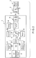
- FIG. 2 is a view illustrating a configuration which generates energy for use in a treatment in the energy treatment system 1.
- the energy for use in the treatment includes high-frequency current, ultrasonic vibration, etc. which are directly applied to the treated target in the treatment, and also includes energy (e.g. vibration generating electric power for generating ultrasonic vibration) for generating energy that is applied to the treated target.
- the electric supplier unit 6 includes an electric-supplier-side resonator 21.
- the electric-supplier-side resonator 21 is a resonance circuit in which an electric supplier coil 22 and an electric-supplier-side capacitor 23 are electrically connected in parallel relative to each other.
- the electric power source 5 supplies DC electric power from a battery (not shown), which is provided in the electric power source 5, to the electric-supplier-side resonator 21.
- electric power from a plug socket is converted to DC electric power by a converter circuit (not shown) which is provided in the electric power source 5, and the DC electric power is supplied to the electric-supplier-side resonator 21.
- the inductance of the electric supplier coil 22 and the capacitance of the electric-supplier-side capacitor 23 are set in such a state that the electric-supplier-side resonator 21 electrically resonates at a resonance frequency f0.
- the electric-supplier-side resonator (electric-supplier-side resonance circuit) 21 electrically resonates (naturally vibrates) at the resonance frequency (natural frequency) f0.
- the DC electric power which is supplied to the electric-supplier-side resonator 21, is converted to AC electric power (AC current) of the resonance frequency f0.
- the energy treatment instrument 2 includes an electric-receiver-side resonator 25.
- the electric-receiver-side resonator 25 is a resonance circuit in which an electric receiver coil 26 and an electric-receiver-side capacitor 27 are electrically connected in parallel relative to each other.
- a magnetic field occurs.
- a magnetic force is being emitted from the magnetic force emission surface 6A of the electric supplier unit 6.
- the inductance of the electric receiver coil 26 and the capacitance of the electric-receiver-side capacitor 27 are set in such a state that the electric-receiver-side resonator 25 electrically resonates at the same resonance frequency f0 as the electric-supplier-side resonator 21.
- the electric-receiver-side resonator (electric-receiver-side resonance circuit) 25 electrically resonates at the same resonance frequency (natural frequency) f0 as the electric-supplier-side resonator 21.
- the electric-supplier-side resonator 21 and the electric-receiver-side resonator 25 resonate at the same resonance frequency f0.
- the AC electric power (AC current) of the resonance frequency f0 is supplied from the electric supplier coil 22 to the electric receiver coil 26.
- the resonance frequency at a time when the electric-supplier-side resonator 21 and electric-receiver-side resonator 25 resonate is, for example, 13.56 MHz.
- a contactless electric power transmission method in which electric power is supplied from the electric supplier coil 22 to the electric receiver coil in the state in which the electric-supplier-side resonator 21 (electric supplier coil 22) and the electric-receiver-side resonator 25 (electric receiver coil 26) are not electrically connected (i.e. by wireless transmission) by utilizing, as described above, the resonance phenomenon in which the electric-supplier-side resonator 21 and electric-receiver-side resonator 25 resonate at the same resonance frequency f0, is called "electromagnetic field resonance method".
- an electromagnetic induction method in which electric power is supplied from the electric supplier coil 22 to the electric receiver coil 26 by utilizing electromagnetic induction between the electric supplier coil 22 and the electric receiver coil 26.
- the electromagnetic field resonance method compared to the electromagnetic induction method, even if the distance between the electric supplier coil 22 and the electric receiver coil 26 is large, electric power is supplied from the electric supplier coil 22 to electric receiver coil 26 at high efficiency. For example, if the distance from the energy treatment instrument 2 to the electric supplier unit 6 including the electric-supplier-side resonator 21 is several meters or less, electric power is supplied from the electric supplier coil 22 to electric receiver coil 26 at high efficiency.
- the position and attitude of the energy treatment instrument 2 are adjusted in the state in which a coil axis L of the electric receiver coil 26 passes through the electric supplier unit 6 (electric-supplier-side resonator 21).
- the sensitivity to the magnetic field in the electric receiver coil 26 is enhanced, and the magnetic field, which is generated by the resonance of the electric-supplier-side resonator 21, and the electric receiver coil 26 are coupled more easily.
- the position and attitude of the energy treatment instrument 2 in the state in which the coil axis L of the electric receiver coil 26 passes through the electric supplier unit 6 (electric-supplier-side resonator 21), the supply efficiency of electric power from the electric supplier coil 22 to the electric receiver coil 26 is enhanced.
- the sensitivity to the magnetic field in the electric receiver coil 26 becomes maximum, and the magnetic field, which is generated by the resonance of the electric-supplier-side resonator 21, and the electric receiver coil 26 are coupled still more easily.
- the energy treatment instrument 2 includes a converter circuit 31 which is electrically connected to the electric-receiver-side resonator 25.
- the converter circuit 31 includes a diode and a DC/DC converter, and rectifies AC electric power which has been supplied to the electric receiver coil 26. Thereby, the AC electric power (AC current) of the resonance frequency f0 is converted to DC electric power (DC current).
- the energy treatment instrument 2 includes a relay circuit 32 which is electrically connected to the converter circuit 31, a battery 33 which is an accumulator, a controller 35 which is electrically connected to the battery 33, and a storage such as a memory.
- the battery 33 is a magnetic member including a magnetic material.
- the controller 35 includes a processor, which includes a CPU (Central Processing Unit) or an ASIC (application specific integrated circuit); a clock signal generating circuit; and a protection circuit.
- the storage 36 stores, for example, a control program which is executed by the controller 35. Electric power is supplied from the battery 33 to the controller 35, and thereby a clock signal is generated by the clock signal generating circuit, and the controller 35 is activated. In addition, by being activated, the controller 35 executes control by the protection circuit in such a state that overcharge, over-discharge and overcurrent of the battery 33 are prevented.
- the relay circuit 32 is electrically connected to the battery 33 and controller 35, and the controller 35 controls the relay circuit 32.
- the energy treatment instrument 2 includes an operation switch 37 which is electrically connected to the controller 35, and a driving circuit 38 which is an energy generator that is electrically connected to the relay circuit 32 and controller 35.
- the operation switch 37 is provided in the inside of the held unit 3, and the open state and closed state of the operation switch 37 are changed over based on an operation input in the energy operation input button 16.
- the controller 35 detects the input of the energy operation in the energy operation input button 16.
- the controller 35 controls the relay circuit 32 and driving circuit 38.
- the relay circuit 32 includes a change-over switch 41.
- the change-over switch 41 includes electrical contact points X1 to X3.
- the controller 35 controls the change-over switch 41, thereby electrically connecting the electrical contact point X1 and electrical contact point X2.
- the electric power which has been received by the electric receiver coil 26 and has been converted to DC electric power by the converter circuit 31, is supplied to the battery 33, and the electric power is accumulated in the battery (accumulator) 33.
- the controller 35 controls the change-over switch 41, thereby electrically connecting the electrical contact point X1 and electrical contact point X3.
- DC electric power is supplied from the battery 33 to the driving circuit 38, and the driving circuit 38 is driven.
- the driving circuit 38 includes a converter circuit which converts the DC electric power to vibration generating electric power (AC electric power) for generating ultrasonic vibration, and a converter circuit which converts the DC electric power to high-frequency electric power.
- the controller 35 controls the driving circuit 38, thereby converting the DC electric power, which is supplied from the battery 33, to vibration generating electric power and high-frequency electric power, and outputting the vibration generating electric power and high-frequency electric power from the driving circuit 38. Accordingly, by using the electric power which is supplied from the electric supplier coil 22 to the electric receiver coil 26, the driving circuit (energy generator) 38 generates energy (vibration generating electric power and high-frequency electric power) which is used in a treatment.
- the driving circuit 38 is electrically connected via electrical paths 42A and 42B to an ultrasonic transducer 43 which is a vibration generator that is disposed in the inside of the held unit 3.
- an ultrasonic transducer 43 which is a vibration generator that is disposed in the inside of the held unit 3.
- the driving circuit 38 is electrically connected to the treatment portion 17 of the vibration transmitter 8 via an electrical path 45A, and is electrically connected to the jaw 18 via an electrical path 45B.
- the treatment portion 17 and jaw 18 function as electrodes of high-frequency electric powers with mutually different electric potentials.
- FIG. 3 is a view which schematically illustrates an internal configuration of the held unit 3.
- FIG. 3 illustrates a cross section perpendicular to the width direction of the held unit 3.
- the ultrasonic transducer 43 is coupled to a proximal portion of the vibration transmitter 8 in the inside of the case main body 11, and extends along the longitudinal axis C, with the axial center thereof substantially agreeing with the longitudinal axis C.
- the ultrasonic vibration which is generated in the ultrasonic transducer 43, is transmitted to the treatment portion 17 from the proximal side toward the distal side in the vibration transmitter 8.
- the ultrasonic transducer 43 includes piezoelectric elements 46A to 46D which convert AC current (vibration generating current) to vibration; electrode members 47A and 47B which apply a voltage to the piezoelectric elements 46A to 46D; and a back-mass 48 which holds the piezoelectric elements 46A to 46D between the back-mass 48 and the vibration transmitter 8 in a direction along the longitudinal axis C.
- the electrode members 47A and 47B are formed of a magnetic material such as stainless steel.
- the back-mass 48 may be formed of a non-magnetic material such as duralumin, titanium or copper, or may be formed of a magnetic material such as stainless steel. Accordingly, the ultrasonic transducer 43 is a magnetic member including a magnetic material.
- a circuit unit 50 is disposed in the inside of the case main body 11.
- the circuit unit 50 is composed of the above-described converter circuit 31, relay circuit 32, controller 35 and driving circuit 38.
- the circuit unit 50 is located on a side opposite to the stationary handle 12 and movable handle 13 with respect to the longitudinal axis C.
- fixing screws which fix the above-described circuits to a board, and a voltage transformer such as a DC/DC converter included in the above-described circuits, are formed of a magnetic material. Accordingly, the circuit unit 50 is a magnetic member including a magnetic material.
- the sheath 7 includes a movable cylindrical portion 51 which extends from the inside of the case main body 11 toward the distal side along the longitudinal axis C.
- a cylindrical slider member 52 is provided on an outer peripheral surface of the movable cylindrical portion 51, and the movable handle 13 is coupled to the slider member 52 in the inside of the case main body 11.
- a cylindrical elastic member 53 is provided on the outer peripheral surface of the movable cylindrical portion 51, the elastic member 53 extending along the longitudinal axis C, with the axial center thereof substantially agreeing with the longitudinal axis C.
- One end (proximal end) of the elastic member 53 is connected to the slider member 52, and the other end (distal end) of the elastic member 53 is connected to the movable cylindrical portion 51.
- the slider member 52 and elastic member 53 are located on the distal side with respect to the ultrasonic transducer 43 and circuit unit 50.
- the elastic member 53 contracts.
- the elastic member 53 is a magnetic member including a magnetic material.
- the above-described battery 33 is disposed, and the above-described operation switch 37 is disposed at such a position that the operation switch 37 can be pushed by the energy operation input button 16.
- the battery 33 is located more distant from the case main body 11 (longitudinal axis C).
- an urging member 55 is attached to the stationary handle 12, and the energy operation input button 16 is urged by the urging member 55 to a position where the operation switch 37 is not pushed (i.e. a position where the operation switch 37 is set in the open state). Since the urging member 55 includes, for example, iron, the urging member 55 is a magnetic member which is formed of a magnetic material.
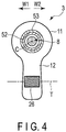
- FIG. 4 is a view illustrating the internal configuration of the held unit 3 by a cross section perpendicular to the longitudinal axis C which passes through the electric receiver coil 26.
- the electric receiver coil 26 is disposed in the inside of the stationary handle 12.
- the battery 33 is located more distant from the case main body 11 (longitudinal axis C).
- the electric receiver coil 26 is located between the battery 33 and the operation switch 37.
- the electric receiver coil 26 is helically wound around a coil axis T.
- the coil axis T of the electric receiver coil 26 extends substantially parallel to the width direction of the held unit 3 (directions of an arrow W1 and an arrow W2 in FIG. 4 ).
- the coil axis T of the electric receiver coil 26 extends substantially perpendicular to a cross section which is perpendicular to the width direction of the held unit 3 shown in FIG. 3 .
- the coil axis T is an imaginary axis which extends also in a region where the coil 26 is not wound (e.g. an outside of the energy treatment instrument 2).
- the coil axis T of the electric receiver coil 26 passes through a position which is distant from each of the above-described magnetic members (sheath 7, jaw 18, battery 33, ultrasonic transducer 43, elastic member 53 and urging member 55 etc.).
- the coil axis T of the electric receiver coil 26 passes through a position which is distant from the above-described magnetic members (7, 18, 33, 43, 50, 53, 55).
- the coil axis T of the electric receiver coil 26 passes through a position which is apart from the above-described magnetic members (7, 18, 33, 43, 50, 53, 55).
- the electric receiver coil 26 is located in the inside of the stationary handle 12, and the coil axis T of the electric receiver coil 26 is substantially parallel to the width direction of the held unit 3.
- the coil axis T of the electric receiver coil 26 passes through a position which is more distant from the longitudinal axis C than an outer peripheral surface of the elastic member 53.
- the coil axis T of the electric receiver coil 26 passes through a position which is more apart from the longitudinal axis C than the outer peripheral surface of the elastic member 53 which is a magnetic member that extends along the longitudinal axis C, with the axial center thereof substantially agreeing with the longitudinal axis C.
- the coil axis T of the electric receiver coil 26 passes through a position which is more distant from the longitudinal axis C than the outer peripheral surface of the elastic member 53.
- the coil axis T of the electric receiver coil 26 passes through a position which is more distant from the longitudinal axis C than the outer peripheral surface of each of the sheath 7 and ultrasonic transducer 43 which are other magnetic members that extend along the longitudinal axis C, with the axial centers thereof substantially agreeing with the longitudinal axis C.
- the coil axis T of the electric receiver coil 26 passes through a position which is distant from the above-described magnetic members (7, 18, 33, 43, 50, 53, 55).
- the coil axis T of the electric receiver coil 26 passes through a position which is distant from the above-described magnetic members (7, 18, 33, 43, 50, 53, 55). Accordingly, in all cross sections perpendicular to the longitudinal axis C, the coil axis T of the electric receiver coil 26 passes through a position which is distant from the above-described magnetic members (7, 18, 33, 43, 50, 53, 55).
- the coil axis T of the electric receiver coil 26 passes through a position which is distant from the above-described magnetic members (7, 18, 33, 43, 50, 53, 55), and each of the magnetic members (7, 18, 33, 43, 50, 53, 55) is located distant from the coil axis T of the electric receiver coil 26.
- the coil axis T of the electric receiver coil 26 extends in the state in which the coil axis T passes through none of the magnetic members (7, 18, 33, 43, 50, 53, 55).
- AC electric power (AC current) of the resonance frequency f0 is supplied from the electric supplier coil 22 to the electric receiver coil 26.
- the electric receiver coil 26 receives electric power from the electric supplier coil 22.
- the electrical contact point X1 and electrical contact point X2 in the change-over switch 41 of the relay circuit 32 are electrically connected by the control of the controller 35.
- the electric power, which has been received by the electric receiver coil 26 is converted to DC electric power by the converter circuit 31, and the DC electric power is accumulated in the battery 33.
- the sheath 7, the treatment portion 17 of the vibration transmitter 8, and the jaw 18 are inserted into a body cavity through the hole of the trocar which is fixed to the body wall. Then, a treatment target, such as a biological tissue, is disposed between the treatment portion 17 and the jaw 18, and the movable handle 13 is closed relative to the stationary handle 12. Thereby, the jaw 18 is closed relative to the treatment portion 17, and the treated target is grasped between the treatment portion 17 and the jaw 18. At this time, the elastic member 53 contracts, and the grasping force between treatment portion 17 and jaw 18 increases.
- a treatment target such as a biological tissue
- an energy operation is input by the energy operation input button 16.
- the controller 35 has detected the input of the energy operation, the electrical contact point X1 and electrical contact point X3 in the change-over switch 41 of the relay circuit 32 are electrically connected by the control of the controller 35.
- DC electric power is supplied from the battery 33 to the driving circuit 38, and energy for use in the treatment is generated in the driving circuit (energy generator) 38.
- the driving circuit 38 generates vibration generating electric power and high-frequency electric power by using the electric power which is supplied to the electric receiver coil 26.
- the vibration generating electric power being supplied from the driving circuit 38 to the ultrasonic transducer 43
- ultrasonic vibration is generated by the ultrasonic transducer 43.
- the generated ultrasonic vibration is transmitted to the treatment portion 17 from the proximal side toward the distal side in the vibration transmitter 8.
- the treatment portion 17 vibrates by ultrasonic vibration.
- the treated target is cut and open and, at the same time, coagulated by frictional heat between the treatment portion 17 and the treated target.
- the high-frequency energy high-frequency electric power
- the coil axis T of the electric receiver coil 26 passes through a position which is distant from the above-described magnetic members (sheath 7, jaw 18, battery 33, ultrasonic transducer 43, elastic member 53 and urging member 55 etc.), and each of the magnetic members (7, 18, 33, 43, 50, 53, 55) is located distant from the coil axis T of the electric receiver coil 26.
- the magnetic field which is generated by the resonance of the electric-supplier-side resonator 21, is effectively prevented from being shielded by the magnetic members (7, 18, 33, 43, 50, 53, 55) before the magnetic field is coupled to the electric receiver coil 26.
- the electric receiver coil 26 is properly coupled to the magnetic field generated by the resonance of the electric-supplier-side resonator 21.
- the electric-supplier-side resonator 21 electrically resonating, the electric-supplier-side resonator 21 and the electric-receiver-side resonator 25 properly resonate at the same resonance frequency f0.
- electric power is properly supplied from the electric supplier coil 22 to the electric receiver coil 26 by the electromagnetic field resonance method (by wireless transmission), and the transmission efficiency of electric power from the electric supplier coil 22 to electric receiver coil 26 can be secured. Since the transmission efficiency of electric power from the electric supplier coil 22 to electric receiver coil 26 is secured, the supply efficiency of energy for use in the treatment, which is supplied from the driving circuit 38, can also be secured.
- the principal component of the bone of the hand is calcium phosphate, and is a non-magnetic material.
- the magnetic permeability of the bone is about 1.256627 ⁇ 10 -6 [H/m], and is substantially equal to the magnetic permeability (1.256637 ⁇ 10 -6 [H/m]) of air.
- each electric receiver coil 26A to 26C is wound around the corresponding coil axis (corresponding one of T1 to T3).
- the extending direction of the coil axis (corresponding one of T1 to T3) of each of the electric receiver coils 26A to 26C is different from the extending directions of the coil axes (corresponding two of T1 to T3) of the other electric receiver coils (corresponding two of 26A to 26C).
- the extending direction of the coil axis T1 of the electric receiver coil 26A is different from the extending directions of the coil axes T2 and T3 of the other electric receiver coils 26B and 26C.
- a bar antenna 57 is formed by the three electric receiver coils 26A to 26C.
- each of the coil axes T1 to T3 is an imaginary axis which extends also in a region where the corresponding electric receiver coil (corresponding one of 26A to 26C) is not wound.
- each of the coil axes T1 to T3 of the electric receiver coils 26A to 26C passes through a position which is distant from the magnetic members (sheath 7, jaw 18, battery 33, ultrasonic transducer 43, elastic member 53 and urging member 55 etc.).
- each of the coil axes T1 to T3 of the electric receiver coils 26A to 26C passes through a position which is distant from the above-described magnetic members (7, 18, 33, 43, 50, 53, 55).
- each of the coil axes T1 to T3 of the electric receiver coils 26A to 26C passes through a position which is more distant from the longitudinal axis C than the outer peripheral surface of the elastic member 53. Accordingly, in a projection from each of one side and the other side (distal side and proximal side) of the direction along the longitudinal axis C, each of the coil axes T1 to T3 of the electric receiver coils 26A to 26C passes through a position which is more distant from the longitudinal axis C than the outer peripheral surface of the elastic member 53.
- each of the coil axes T1 to T3 of the electric receiver coils 26A to 26C passes through a position which is more distant from the longitudinal axis C than the outer peripheral surface of each of the sheath 7 and ultrasonic transducer 43 which are other magnetic members that extend along the longitudinal axis C, with the axial centers thereof substantially agreeing with the longitudinal axis C.
- each of the coil axes T1 to T3 of the electric receiver coils 26A to 26C passes through a position which is distant from the above-described magnetic members (7, 18, 33, 43, 50, 53, 55).
- each of the coil axes T1 to T3 of the electric receiver coils 26A to 26C passes through a position which is apart from the magnetic members (7, 18, 33, 43, 50, 53, 55).
- each of the coil axes T1 to T3 of the electric receiver coils 26A to 26C passes through a position which is distant from the above-described magnetic members (7, 18, 33, 43, 50, 53, 55), and each of the magnetic members (7, 18, 33, 43, 50, 53, 55) is located distant from the coil axes T1 to T3 of the electric receiver coils 26A to 26C.
- each of the coil axes T1 to T3 of the electric receiver coils 26A to 26C extends in the state in which each of the coil axes T1 to T3 passes through none of the magnetic members (7, 18, 33, 43, 50, 53, 55).
- the magnetic field which is generated by the resonance of the electric-supplier-side resonator 21, is effectively prevented from being shielded by the magnetic members (7, 18, 33, 43, 50, 53, 55) before the magnetic field is coupled to each of the electric receiver coils 26A to 26C.
- the magnetic members (7, 18, 33, 43, 50, 53, 55) are not located on the coil axis (corresponding one of T1 to T3) of each of the electric receiver coils 26A to 26C and in the vicinity thereof, each of the electric receiver coils 26A to 26C is properly coupled to the magnetic field generated by the resonance of the electric-supplier-side resonator 21.
- electric power is properly supplied from the electric supplier coil 22 to each of the electric receiver coils 26A to 26C by the electromagnetic field resonance method (by wireless transmission), and the transmission efficiency of electric power from the electric supplier coil 22 to each of the electric receiver coils 26A to 26C can be secured.
- the electric receiver coil (e.g. 26B) of the electric receiver coils 26A to 26C passes through the electric supplier unit 6, and the sensitivity to the magnetic field in the electric receiver coil (26B), the coil axis (T2) of which passes through the electric supplier unit 6, increases.
- the electric receiver coil (e.g. 26B) in which the sensitivity to the magnetic field increases, is properly coupled to the magnetic field generated by the resonance of the electric-supplier-side resonator 21.
- the supply efficiency of electric power from the electric supplier coil 22 to at least one (e.g. 26B) of the electric receiver coils 26A to 26C is secured. Thereby, even when the position and attitude of the energy treatment instrument have changed, electric power is stably supplied from the electric supplier coil 22 to any one of the electric receiver coils 26A to 26C.
- the extending direction of the coil axis (e.g. corresponding one of T1 to T3) of each of the electric receiver coils (e.g. 26A to 26C) is different from the extending direction of the coil axis (e.g. at least one of T1 to T3) of at least one of the other electric receiver coils (e.g. corresponding two of 26A to 26C).
- the plural electric receiver coils (26A to 26C) may be disposed in one electric-receiver-side resonator (electric-receiver-side resonance circuit) 25.
- a plurality of electric-receiver-side resonators (electric-receiver-side resonance circuits) 25 may be provided, and each of the plural electric receiver coils (26A to 26C) may be disposed in the corresponding electric-receiver-side resonator 25.
- each of the plural electric-receiver-side resonators 25 is electrically connected to the converter circuit 31, and the converter circuit 31 converts AC electric power, which has been received by each of the electric-receiver-side resonators 25, to DC electric power which can be accumulated in the battery 33.
- a loop antenna 58 is formed by a plurality (three in this modification) of electric receiver coils 26A to 26C.
- the loop antenna 58 has a greater cross-sectional area perpendicular to the coil axis (corresponding one of T1 to T3) of each of the electric receiver coils 26A to 26C.
- the sensitivity to the magnetic field in each of the electric receiver coils 26A to 26C increases. Accordingly, the supply efficiency of electric power from the electric supplier coil 22 to each of the electric receiver coils 26A to 26C is enhanced.
- the electric power, which has been received by the electric receiver coil 26 and has been converted to DC electric power by the converter circuit 31, is directly supplied to the driving circuit 38.
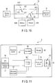
- the controller 35 controls the change-over switch 41A, thereby electrically connecting the electrical contact point X1 and electrical contact point X3 in the switch 41A.
- the controller 35 controls the change-over switch 41B, thereby setting the change-over switch 41B in the closed state and electrically connecting the electrical contact point Y1 and electrical contact point Y2.
- the electric power, which has been received by the electric receiver coil 26 and has been converted to DC electric power by the converter circuit 31 is directly supplied to the driving circuit 38, and also the electric power accumulated in the battery 33 is supplied to the driving circuit 38.
- the electrical contact point X1 and electrical contact point X2 are electrically connected in the switch 41C, and the change-over switch 41D is controlled and set in the open state.
- the electric power which has been received by the electric receiver coil 26 and has been converted to DC electric power by the converter circuit 31, is accumulated in the battery (accumulator) 33A which is less in residual charge amount.
- the controller 35 controls the change-over switches 41C and 41D, thereby supplying electric power from the converter circuit 31 to one of the batteries 33A and 33B, which is less in residual charge amount, and also supplying electric power from the battery 33A, 33B, which is greater in residual charge amount, to the driving circuit 38.
- the electrical contact point X1 and electrical contact point X3 are electrically connected in the switch 41C, and the change-over switch 41D is controlled and, thereby, the electrical, contact point X'1 and electrical contact point X'2 are electrically connected.
- the electric power which has been received by the electric receiver coil 26 and has been converted to DC electric power by the converter circuit 31, is accumulated in the battery (accumulator) 33B which is less in residual charge amount.
- energy is supplied from the battery 33A, which is greater in residual charge amount, to the driving circuit 38, and the energy for use in the treatment is generated by the driving circuit 38.
- the electric power, which the electric receiver coil 26 has received may not be converted to DC electric power in the converter circuit 31, and AC electric power may be supplied to the driving circuit 38.
- an AC/AC converter or the like is provided in the driving circuit 38, and the energy (vibration generating electric power and high-frequency electric power) for use in the treatment is generated in the driving circuit 38 by using the supplied AC electric power.
- the first embodiment relates to the energy treatment instrument 2 which grasps the treated target between the treatment portion 17 and jaw 18 that are inserted in the body cavity
- the above-described configuration can be applied to an energy treatment instrument which is different in kind from the energy treatment instrument 2.
- the jaw 18 is not provided, and the stationary handle 12, movable handle 13 and rotary operation knob 15 are not provided in the held unit (housing) 3.
- the slider member 52 and elastic member 53 are not provided in the energy treatment instrument 70.
- FIG. 12 illustrates the inside of the held unit 3 by a cross section perpendicular to the width direction of the held unit 3.
- vibration generating electric power is supplied from the driving circuit 38 to the ultrasonic transducer 43, and ultrasonic vibration is generated by the ultrasonic transducer 43.
- the generated ultrasonic vibration is transmitted to the treatment portion 17 through the vibration transmitter 8.
- a treated target is abraded by the ultrasonic vibration being transmitted to the treatment portion 17 in the state in which the treatment portion 17 is put in contact with the treated target.
- the driving circuit 38 high-frequency electric power is generated, and the high-frequency electric power is supplied to the treatment portion 17 at the same time as the transmission of the ultrasonic vibration.
- the circuit unit 50 which includes the converter circuit 31, controller 35 and driving circuit 38, is disposed in the inside of the case main body 11.
- the circuit unit 50 is a magnetic member including a magnetic material.
- the energy operation input button 16 is attached to the case main body 11, and the operation switch 37, the open state and closed state of which are changed over based on the input of the energy operation in the energy operation input button 16, is provided in the inside of the case main body 11.
- the energy operation input button 16 is urged by the urging member 55 to a position where the operation switch 37 is not pushed (i.e. a position where the operation switch 37 is set in the open state).
- the urging member 55 is a magnetic member which is formed of a magnetic material.
- the energy operation input button 16, operation switch 37 and urging member 55 are located on the side opposite to the circuit unit 50 with respect to the longitudinal axis C.
- the electric receiver coil 26 is provided in the inside of the case main body 11.
- the electric receiver coil 26 is located on the proximal side with respect to the circuit unit 50 and urging member 55 (energy operation input button 16), and is located on the side opposite to the circuit unit 50 with respect to the longitudinal axis C.
- the coil axis T which is the center of the electric receiver coil 26, extends substantially parallel to the width direction of the held unit 3.
- the coil axis T of the electric receiver coil 26 passes through a position which is distant from the above-described magnetic members (7, 43, 50, 55), and each of the magnetic members (7, 43, 50, 55) is located distant from the coil axis T of the electric receiver coil 26. Accordingly, in this modification, too, the magnetic field, which is generated by the resonance of the electric-supplier-side resonator 21, is effectively prevented from being shielded by the magnetic members (7, 43, 50, 55) before the magnetic field is coupled to the electric receiver coil 26, and the electric power is properly supplied from the electric supplier coil 22 to the electric receiver coil 26 by the electromagnetic field resonance method (by wireless transmission).
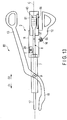
- FIG. 13 illustrates the opening and closing directions of the movable handle 13 in an energy treatment instrument (handpiece) 80 of a seventh modification illustrated in FIG. 13 .
- the jaw 18 and movable handle 13 are rotatable as one piece.
- the jaw 18 and movable handle 13 are rotatable about a rotational axis P which passes through a coupling position to the sheath 7.
- the slider member 52 and elastic member 53 are not provided in the energy treatment instrument 80.
- the energy treatment instrument 80 of this modification is used for ventrotomy or the like.
- FIG. 13 illustrates the inside of the held unit 3 by a cross section perpendicular to the width direction of the held unit 3.
- a transducer case 81 is coupled to the case main body 11 of the held unit 3 from the proximal side, and the ultrasonic transducer 43 is disposed in the inside of the transducer case 81.
- the ultrasonic transducer 43 is coupled to the proximal portion of the vibration transmitter 8.
- the sheath 7, vibration transmitter 8, case main body 11 and ultrasonic transducer 43 extend along the longitudinal axis C, with the centers thereof substantially agreeing with the longitudinal axis C.
- the ultrasonic transducer 43, sheath 7 and jaw 18 are magnetic members including a magnetic material.
- the stationary handle 12 extends from the case body 11 in a direction crossing the longitudinal axis C.
- the stationary handle 12 is located on the side opposite to the movable handle 13 with respect to the longitudinal axis C.
- vibration generating electric power is supplied from the driving circuit 38 to the ultrasonic transducer 43, and ultrasonic vibration is generated by the ultrasonic transducer 43.
- the generated ultrasonic vibration is transmitted to the treatment portion 17 through the vibration transmitter 8.
- high-frequency electric power is supplied from the driving circuit 38 to the treatment portion 17 and jaw 18.
- a ventrotomy treatment is performed by using the ultrasonic vibration and high-frequency electric power.
- the circuit unit 50 which includes the converter circuit 31, controller 35 and driving circuit 38, is disposed in the inside of the transducer case 81.
- the circuit unit 50 is a magnetic member including a magnetic material.
- the energy operation input button 16 is attached to the stationary handle 12, and the operation switch 37, the open state and closed state of which are changed over based on the input of the energy operation in the energy operation input button 16, is provided in the inside of the stationary handle 12.
- the energy operation input button 16 is urged by the urging member 55 to a position where the operation switch 37 is not pushed (i.e. a position where the operation switch 37 is set in the open state).
- the electric receiver coil 26 is provided in the inside of the case main body 11.
- the electric receiver coil 26 is located on the distal side with respect to the circuit unit 50 and urging member 55 (energy operation input button 16), and is located on the side opposite to the circuit unit 50 and urging member 55 with respect to the longitudinal axis C.
- the coil axis T which is the center of the electric receiver coil 26, extends substantially parallel to the width direction of the held unit 3.
- the driving circuit 38 generates vibration generating electric power and high-frequency electric power as energy for use in a treatment, but the restriction to this is unnecessary.
- the above-described configuration may be applied to an energy treatment instrument in which a treated target is grasped between two jaws provided in a distal portion, and a heating element is provided in at least one of the jaws.
- the driving circuit 38 by the electric power received by the electric receiver coil (26; 26A to 26C), the driving circuit 38 generates heat generating electric power (DC electric power or AC electric power) as energy for use in a treatment, and supplies the heat generating electric power to the heating element.
- heat is generated by the heating element, and the heat is applied to the grasped treated target to treat the treated target.
- the above-described configuration is applied to an energy treatment instrument which is provided with a movable portion and which treats a treated target by moving the movable portion.
- an electric motor which generates a driving force for moving the movable portion, is provided, and the driving circuit 38 generates, by the electric power received by the electric receiver coil (26; 26A to 26C), driving electric power for driving the electric motor as energy for use in the treatment.
- the driving circuit 38 when the above-described configuration is applied to an energy treatment instrument having a distal portion provided with a stapler, the driving circuit 38 generates the driving electric power by the electric power received by the electric receiver coil (26; 26A to 26C), and a movable portion provided in the stapler moves by the electric motor being driven by the driving electric power.
- a staple which is accommodated in the inside of the stapler, is pushed by the movable portion, and the staple is pierced through the treated target.
Landscapes
- Health & Medical Sciences (AREA)
- Surgery (AREA)
- Engineering & Computer Science (AREA)
- Life Sciences & Earth Sciences (AREA)
- Molecular Biology (AREA)
- Animal Behavior & Ethology (AREA)
- Veterinary Medicine (AREA)
- Biomedical Technology (AREA)
- Heart & Thoracic Surgery (AREA)
- Medical Informatics (AREA)
- Public Health (AREA)
- Nuclear Medicine, Radiotherapy & Molecular Imaging (AREA)
- General Health & Medical Sciences (AREA)
- Physics & Mathematics (AREA)
- Plasma & Fusion (AREA)
- Otolaryngology (AREA)
- Dentistry (AREA)
- Mechanical Engineering (AREA)
- Surgical Instruments (AREA)
- Charge And Discharge Circuits For Batteries Or The Like (AREA)
Abstract
Description
- The present invention relates to an energy treatment instrument which generates energy by being supplied with electric power, and performs a treatment by using the generated energy.
- Jpn. Pat. Appln. KOKAI Publication No.
2014-68987 - In Jpn. Pat. Appln. KOKAI Publication No.
2014-68987 - The present invention has been made in consideration of the above problem, and the object of the invention is to provide an energy treatment instrument in which electric power is properly supplied without lowering the supply efficiency of electric power, by wireless transmission, from an electric supplier coil to an electric receiver coil.
- To solve the above mentioned problems, according to one aspect of the invention, an energy treatment instrument including: a held unit which has a longitudinal axis, and which is capable of being held; a magnetic member including a magnetic material; an electric-receiver-side resonator including an electric receiver coil which is wound around a coil axis that is located distant from the magnetic member, the electric-receiver-side resonator being configured to resonate at the resonance frequency as an electric-supplier-side resonator including an electric supplier coil, thereby electric power being supplied from the electric supplier coil to the electric receiver coil; and an energy generator configured to generate energy for use in a treatment, by using the electric power supplied to the electric receiver coil.
-
-
FIG. 1 is a schematic view illustrating an energy treatment system according to a first embodiment, -
FIG. 2 is a schematic view illustrating a configuration which generates energy for use in a treatment in the energy treatment system according to the first embodiment, -
FIG. 3 is a schematic view illustrating an internal configuration of a held unit according to the first embodiment, by a cross section perpendicular to a width direction of the held unit, -
FIG. 4 is a schematic view illustrating the internal configuration of the held unit according to the first embodiment, by a cross section perpendicular to a longitudinal axis which passes through an electric receiver coil, -
FIG. 5 is a schematic view illustrating an internal configuration of a held unit according to a first modification, by a cross section perpendicular to the width direction of the held unit, -
FIG. 6 is a schematic view illustrating the internal configuration of the held unit according to the first modification, by a cross section perpendicular to a longitudinal axis which passes through an electric receiver coil, -
FIG. 7 is a perspective view which schematically illustrates a bar antenna which is formed by the electric receiver coil according to the first modification, -
FIG. 8 is a perspective view which schematically illustrates a loop antenna which is formed by an electric receiver coil according to a second modification, -
FIG. 9 is a schematic view illustrating a configuration of a relay circuit according to a third modification, -
FIG. 10 is a schematic view illustrating a configuration of a relay circuit according to a fourth modification, -
FIG. 11 is a schematic view illustrating a configuration which generates energy for use in a treatment in an energy treatment system according to a fifth modification, -
FIG. 12 is a schematic view illustrating an energy treatment instrument according to a sixth modification, and -
FIG. 13 is a schematic view illustrating an energy treatment instrument according to a seventh modification. Description of Embodiments - A first embodiment of the present invention will be described with reference to
FIG. 1 to FIG. 4 .FIG. 1 is a view illustrating anenergy treatment system 1. As illustrated inFIG. 1 , theenergy treatment system 1 includes an energy treatment instrument (handpiece) 2. Theenergy treatment instrument 2 is a cordless treatment instrument which does not include a cable cord. Theenergy treatment instrument 2 includes a held unit (housing) 3 which can be held by a surgeon. The heldunit 3 has a longitudinal axis C. Here, in theenergy treatment instrument 2, one side of a direction along the longitudinal axis C is a distal side (an arrow C1 side inFIG. 1 ), and a side opposite to the distal side is a proximal side (an arrow C2 side inFIG. 1 ). In addition, theenergy treatment system 1 includes anelectric power source 5, and an electric supplier unit (electric supplier device) 6 which is electrically connected to theelectric power source 5. Theelectric supplier unit 6 includes a magneticforce emission surface 6A which can emit a magnetic force. In the present embodiment, theelectric power source 5 andelectric supplier unit 6 are provided as a peripheral device of theenergy treatment instrument 2, and is disposed on, for example, a trolley. - The held
unit 3 of theenergy treatment instrument 2 includes a casemain body 11 which extends along the longitudinal axis C, with the axial center thereof substantially agreeing with the longitudinal axis C; a stationary handle (grip) 12 which extends from the casemain body 11 in a direction crossing the longitudinal axis C; and a movable handle (handle) 13 which is openable and closable relative to thestationary handle 12. In addition, the heldunit 3 includes a rotary operation knob (rotary operation portion) 15 which is coupled to the distal side of the casemain body 11. Therotary operation knob 15 is rotatable relative to the casemain body 11 around the longitudinal axis C. In the heldunit 3, an energy operation input button (energy operation input portion) 16 is attached to that surface of thestationary handle 12, which faces the distal side. In the meantime, the casemain body 11,stationary handle 12,movable handle 13,rotary operation knob 15 and energyoperation input button 16 are formed of a non-magnetic material such as a resin. In addition, the opening and closing directions of themovable handle 13 are substantially parallel to the longitudinal axis C. - The
energy treatment instrument 2 includes asheath 7 which extends along the longitudinal axis C, with the axial center thereof substantially agreeing with the longitudinal axis C. Thesheath 7 is coupled to the distal side of the heldunit 3, in the state in which thesheath 7 is inserted, from the distal side, into the inside of therotary operation knob 15 and the inside of the casemain body 11. Thesheath 7 is a magnetic member including a magnetic material such as stainless steel. In addition, in theenergy treatment instrument 2, avibration transmitter 8 extends from the inside of the casemain body 11 toward the distal side through the inside of thesheath 7. Thevibration transmitter 8 extends along the longitudinal axis C, with the axial center thereof substantially agreeing with the longitudinal axis C. Thevibration transmitter 8 is formed of a material with high vibration transmissivity, such as Ti-6Al-4V or duralumin, and is formed of a non-magnetic material. In addition, atreatment portion 17 is provided in a distal portion of thevibration transmitter 8, and thetreatment portion 17 projects toward the distal side from a distal end of thesheath 7. - In the
energy treatment instrument 2, ajaw 18 is rotatably attached to a distal portion of thesheath 7. By opening or closing themovable handle 13 relative to thestationary handle 12, thejaw 18 opens or closes relative to thetreatment portion 17 of thevibration transmitter 8. Thejaw 18 is a magnetic member including a magnetic material. Here, the magnetic material includes iron, nickel, cobalt, cadmium, and alloys thereof. The non-magnetic material includes copper, aluminum, and a resin. By therotary operation knob 15 rotating around the longitudinal axis C, thesheath 7,vibration transmitter 8 andjaw 18 rotate, together with therotary operation knob 15, about the longitudinal axis C relative to the casemain body 11. In addition, in a treatment, the distal portion of thesheath 7,treatment portion 17 andjaw 18 are inserted into a body cavity, such as a peritoneal cavity, through a hole of a trocar which is fixed to a body wall of the human body. Then, by closing thejaw 18 relative to thetreatment portion 17, a treated target is grasped between thetreatment portion 17 andjaw 18. -
FIG. 2 is a view illustrating a configuration which generates energy for use in a treatment in theenergy treatment system 1. Incidentally, the energy for use in the treatment includes high-frequency current, ultrasonic vibration, etc. which are directly applied to the treated target in the treatment, and also includes energy (e.g. vibration generating electric power for generating ultrasonic vibration) for generating energy that is applied to the treated target. As illustrated inFIG. 2 , theelectric supplier unit 6 includes an electric-supplier-side resonator 21. In the present embodiment, the electric-supplier-side resonator 21 is a resonance circuit in which anelectric supplier coil 22 and an electric-supplier-side capacitor 23 are electrically connected in parallel relative to each other. In one example, theelectric power source 5 supplies DC electric power from a battery (not shown), which is provided in theelectric power source 5, to the electric-supplier-side resonator 21. In another example, electric power from a plug socket is converted to DC electric power by a converter circuit (not shown) which is provided in theelectric power source 5, and the DC electric power is supplied to the electric-supplier-side resonator 21. In the electric-supplier-side resonator 21, the inductance of theelectric supplier coil 22 and the capacitance of the electric-supplier-side capacitor 23 are set in such a state that the electric-supplier-side resonator 21 electrically resonates at a resonance frequency f0. Thus, by DC electric power being supplied to the electric-supplier-side resonator 21, the electric-supplier-side resonator (electric-supplier-side resonance circuit) 21 electrically resonates (naturally vibrates) at the resonance frequency (natural frequency) f0. Thereby, the DC electric power, which is supplied to the electric-supplier-side resonator 21, is converted to AC electric power (AC current) of the resonance frequency f0. - The
energy treatment instrument 2 includes an electric-receiver-side resonator 25. In the present embodiment, the electric-receiver-side resonator 25 is a resonance circuit in which anelectric receiver coil 26 and an electric-receiver-side capacitor 27 are electrically connected in parallel relative to each other. By the electric-supplier-side resonator 21 resonating, a magnetic field occurs. At this time, a magnetic force is being emitted from the magneticforce emission surface 6A of theelectric supplier unit 6. In the electric-receiver-side resonator 25, the inductance of theelectric receiver coil 26 and the capacitance of the electric-receiver-side capacitor 27 are set in such a state that the electric-receiver-side resonator 25 electrically resonates at the same resonance frequency f0 as the electric-supplier-side resonator 21. Thus, by the magnetic field generated by the resonance of the electric-supplier-side resonator 21 being coupled to theelectric receiver coil 26 of the electric-receiver-side resonator 25, the electric-receiver-side resonator (electric-receiver-side resonance circuit) 25 electrically resonates at the same resonance frequency (natural frequency) f0 as the electric-supplier-side resonator 21. Specifically, by the coupling between the magnetic field, which is generated by the resonance of the electric-supplier-side resonator 21, and theelectric receiver coil 26, the electric-supplier-side resonator 21 and the electric-receiver-side resonator 25 resonate at the same resonance frequency f0. By the electric-supplier-side resonator 21 and the electric-receiver-side resonator 25 resonating at the same resonance frequency f0, the AC electric power (AC current) of the resonance frequency f0 is supplied from theelectric supplier coil 22 to theelectric receiver coil 26. The resonance frequency at a time when the electric-supplier-side resonator 21 and electric-receiver-side resonator 25 resonate is, for example, 13.56 MHz. - A contactless electric power transmission method, in which electric power is supplied from the
electric supplier coil 22 to the electric receiver coil in the state in which the electric-supplier-side resonator 21 (electric supplier coil 22) and the electric-receiver-side resonator 25 (electric receiver coil 26) are not electrically connected (i.e. by wireless transmission) by utilizing, as described above, the resonance phenomenon in which the electric-supplier-side resonator 21 and electric-receiver-side resonator 25 resonate at the same resonance frequency f0, is called "electromagnetic field resonance method". As the contactless electric power transmission method in which electric power is supplied from theelectric supplier coil 22 to the electric receiver coil in the state in which theelectric supplier coil 22 and theelectric receiver coil 26 are not electrically connected, there is known, aside from the electromagnetic field resonance method, an electromagnetic induction method in which electric power is supplied from theelectric supplier coil 22 to theelectric receiver coil 26 by utilizing electromagnetic induction between theelectric supplier coil 22 and theelectric receiver coil 26. In the electromagnetic field resonance method, compared to the electromagnetic induction method, even if the distance between theelectric supplier coil 22 and theelectric receiver coil 26 is large, electric power is supplied from theelectric supplier coil 22 toelectric receiver coil 26 at high efficiency. For example, if the distance from theenergy treatment instrument 2 to theelectric supplier unit 6 including the electric-supplier-side resonator 21 is several meters or less, electric power is supplied from theelectric supplier coil 22 toelectric receiver coil 26 at high efficiency. - In addition, in the electromagnetic field resonance method, the position and attitude of the
energy treatment instrument 2 are adjusted in the state in which a coil axis L of theelectric receiver coil 26 passes through the electric supplier unit 6 (electric-supplier-side resonator 21). Thereby, the sensitivity to the magnetic field in theelectric receiver coil 26 is enhanced, and the magnetic field, which is generated by the resonance of the electric-supplier-side resonator 21, and theelectric receiver coil 26 are coupled more easily. Thus, by adjusting the position and attitude of theenergy treatment instrument 2 in the state in which the coil axis L of theelectric receiver coil 26 passes through the electric supplier unit 6 (electric-supplier-side resonator 21), the supply efficiency of electric power from theelectric supplier coil 22 to theelectric receiver coil 26 is enhanced. In particular, by adjusting the position and attitude of theenergy treatment instrument 2 in the state in which the coil axis L of theelectric receiver coil 26 is perpendicularly cross to the magneticforce emission surface 6A of theelectric supplier unit 6, the sensitivity to the magnetic field in theelectric receiver coil 26 becomes maximum, and the magnetic field, which is generated by the resonance of the electric-supplier-side resonator 21, and theelectric receiver coil 26 are coupled still more easily. - The
energy treatment instrument 2 includes aconverter circuit 31 which is electrically connected to the electric-receiver-side resonator 25. Theconverter circuit 31 includes a diode and a DC/DC converter, and rectifies AC electric power which has been supplied to theelectric receiver coil 26. Thereby, the AC electric power (AC current) of the resonance frequency f0 is converted to DC electric power (DC current). In addition, theenergy treatment instrument 2 includes arelay circuit 32 which is electrically connected to theconverter circuit 31, abattery 33 which is an accumulator, acontroller 35 which is electrically connected to thebattery 33, and a storage such as a memory. Thebattery 33 is a magnetic member including a magnetic material. Thecontroller 35 includes a processor, which includes a CPU (Central Processing Unit) or an ASIC (application specific integrated circuit); a clock signal generating circuit; and a protection circuit. In addition, thestorage 36 stores, for example, a control program which is executed by thecontroller 35. Electric power is supplied from thebattery 33 to thecontroller 35, and thereby a clock signal is generated by the clock signal generating circuit, and thecontroller 35 is activated. In addition, by being activated, thecontroller 35 executes control by the protection circuit in such a state that overcharge, over-discharge and overcurrent of thebattery 33 are prevented. Therelay circuit 32 is electrically connected to thebattery 33 andcontroller 35, and thecontroller 35 controls therelay circuit 32. - The
energy treatment instrument 2 includes anoperation switch 37 which is electrically connected to thecontroller 35, and a drivingcircuit 38 which is an energy generator that is electrically connected to therelay circuit 32 andcontroller 35. Theoperation switch 37 is provided in the inside of the heldunit 3, and the open state and closed state of theoperation switch 37 are changed over based on an operation input in the energyoperation input button 16. By detecting the open state or closed state of theoperation switch 37, thecontroller 35 detects the input of the energy operation in the energyoperation input button 16. In addition, based on the detection result of the input of the energy operation, thecontroller 35 controls therelay circuit 32 and drivingcircuit 38. - The
relay circuit 32 includes a change-over switch 41. The change-over switch 41 includes electrical contact points X1 to X3. In the state in which the energy operation is not input by the energyoperation input button 16, thecontroller 35 controls the change-over switch 41, thereby electrically connecting the electrical contact point X1 and electrical contact point X2. Thereby, the electric power, which has been received by theelectric receiver coil 26 and has been converted to DC electric power by theconverter circuit 31, is supplied to thebattery 33, and the electric power is accumulated in the battery (accumulator) 33. On the other hand, in the state in which the energy operation is being input by the energyoperation input button 16, thecontroller 35 controls the change-over switch 41, thereby electrically connecting the electrical contact point X1 and electrical contact point X3. Thereby, DC electric power is supplied from thebattery 33 to the drivingcircuit 38, and the drivingcircuit 38 is driven. - The driving
circuit 38 includes a converter circuit which converts the DC electric power to vibration generating electric power (AC electric power) for generating ultrasonic vibration, and a converter circuit which converts the DC electric power to high-frequency electric power. In the state in which the energy operation is being input, thecontroller 35 controls the drivingcircuit 38, thereby converting the DC electric power, which is supplied from thebattery 33, to vibration generating electric power and high-frequency electric power, and outputting the vibration generating electric power and high-frequency electric power from the drivingcircuit 38. Accordingly, by using the electric power which is supplied from theelectric supplier coil 22 to theelectric receiver coil 26, the driving circuit (energy generator) 38 generates energy (vibration generating electric power and high-frequency electric power) which is used in a treatment. - The driving
circuit 38 is electrically connected viaelectrical paths ultrasonic transducer 43 which is a vibration generator that is disposed in the inside of the heldunit 3. By the vibration generating electric power being supplied from the drivingcircuit 36 to theultrasonic transducer 43, ultrasonic vibration occurs in theultrasonic transducer 43. In addition, the drivingcircuit 38 is electrically connected to thetreatment portion 17 of thevibration transmitter 8 via anelectrical path 45A, and is electrically connected to thejaw 18 via anelectrical path 45B. By the high-frequency electric power being supplied from the drivingcircuit 38 to thetreatment portion 17 andjaw 18, thetreatment portion 17 andjaw 18 function as electrodes of high-frequency electric powers with mutually different electric potentials. -
FIG. 3 is a view which schematically illustrates an internal configuration of the heldunit 3.FIG. 3 illustrates a cross section perpendicular to the width direction of the heldunit 3. As illustrated inFIG. 3 , theultrasonic transducer 43 is coupled to a proximal portion of thevibration transmitter 8 in the inside of the casemain body 11, and extends along the longitudinal axis C, with the axial center thereof substantially agreeing with the longitudinal axis C. The ultrasonic vibration, which is generated in theultrasonic transducer 43, is transmitted to thetreatment portion 17 from the proximal side toward the distal side in thevibration transmitter 8. Theultrasonic transducer 43 includespiezoelectric elements 46A to 46D which convert AC current (vibration generating current) to vibration;electrode members piezoelectric elements 46A to 46D; and a back-mass 48 which holds thepiezoelectric elements 46A to 46D between the back-mass 48 and thevibration transmitter 8 in a direction along the longitudinal axis C. Theelectrode members mass 48 may be formed of a non-magnetic material such as duralumin, titanium or copper, or may be formed of a magnetic material such as stainless steel. Accordingly, theultrasonic transducer 43 is a magnetic member including a magnetic material. - Besides, a
circuit unit 50 is disposed in the inside of the casemain body 11. Thecircuit unit 50 is composed of the above-describedconverter circuit 31,relay circuit 32,controller 35 and drivingcircuit 38. In the present embodiment, thecircuit unit 50 is located on a side opposite to thestationary handle 12 andmovable handle 13 with respect to the longitudinal axis C. In thecircuit unit 50, fixing screws which fix the above-described circuits to a board, and a voltage transformer such as a DC/DC converter included in the above-described circuits, are formed of a magnetic material. Accordingly, thecircuit unit 50 is a magnetic member including a magnetic material. - In addition, the
sheath 7 includes a movablecylindrical portion 51 which extends from the inside of the casemain body 11 toward the distal side along the longitudinal axis C. Acylindrical slider member 52 is provided on an outer peripheral surface of the movablecylindrical portion 51, and themovable handle 13 is coupled to theslider member 52 in the inside of the casemain body 11. In addition, a cylindricalelastic member 53 is provided on the outer peripheral surface of the movablecylindrical portion 51, theelastic member 53 extending along the longitudinal axis C, with the axial center thereof substantially agreeing with the longitudinal axis C. One end (proximal end) of theelastic member 53 is connected to theslider member 52, and the other end (distal end) of theelastic member 53 is connected to the movablecylindrical portion 51. In the present embodiment, in the inside of the casemain body 11, theslider member 52 andelastic member 53 are located on the distal side with respect to theultrasonic transducer 43 andcircuit unit 50. - By closing the
movable handle 13 relative to thestationary handle 12, theslider member 52, theelastic member 53, and the movablecylindrical portion 52 of thesheath 7 move toward the distal side, and thejaw 18 closes relative to thetreatment portion 17. In addition, by thejaw 18 abutting on the grasped treated target and by the treated target being compressed to some degree, theslider member 52 moves toward the distal side relative to the movablecylindrical portion 51, and theelastic member 53 contracts. Specifically, by closing themovable handle 13 relative to thestationary handle 12, theelastic member 53 contracts. By theelastic member 53 contracting, the grasping force between thetreatment portion 17 andjaw 18 increases. Theelastic member 53 is a magnetic member including a magnetic material. - In addition, in the inside of the
stationary handle 12, the above-describedbattery 33 is disposed, and the above-describedoperation switch 37 is disposed at such a position that theoperation switch 37 can be pushed by the energyoperation input button 16. In the present embodiment, compared to theoperation switch 37, thebattery 33 is located more distant from the case main body 11 (longitudinal axis C). Furthermore, an urgingmember 55 is attached to thestationary handle 12, and the energyoperation input button 16 is urged by the urgingmember 55 to a position where theoperation switch 37 is not pushed (i.e. a position where theoperation switch 37 is set in the open state). Since the urgingmember 55 includes, for example, iron, the urgingmember 55 is a magnetic member which is formed of a magnetic material. -
FIG. 4 is a view illustrating the internal configuration of the heldunit 3 by a cross section perpendicular to the longitudinal axis C which passes through theelectric receiver coil 26. As illustrated inFIG. 3 andFIG. 4 , theelectric receiver coil 26 is disposed in the inside of thestationary handle 12. In the present embodiment, compared to theelectric receiver coil 26, thebattery 33 is located more distant from the case main body 11 (longitudinal axis C). In the inside of thestationary handle 12, theelectric receiver coil 26 is located between thebattery 33 and theoperation switch 37. Theelectric receiver coil 26 is helically wound around a coil axis T. In this embodiment, the coil axis T of theelectric receiver coil 26 extends substantially parallel to the width direction of the held unit 3 (directions of an arrow W1 and an arrow W2 inFIG. 4 ). Thus, the coil axis T of theelectric receiver coil 26 extends substantially perpendicular to a cross section which is perpendicular to the width direction of the heldunit 3 shown inFIG. 3 . Incidentally, the coil axis T is an imaginary axis which extends also in a region where thecoil 26 is not wound (e.g. an outside of the energy treatment instrument 2). - In the cross section shown in
FIG. 3 , the coil axis T of theelectric receiver coil 26 passes through a position which is distant from each of the above-described magnetic members (sheath 7,jaw 18,battery 33,ultrasonic transducer 43,elastic member 53 and urgingmember 55 etc.). Thus, in a projection from each of one side (an arrow W1 side inFIG. 4 ) and the other side (an arrow W2 side inFIG. 4 ) of the width direction of the heldunit 3, the coil axis T of theelectric receiver coil 26 passes through a position which is distant from the above-described magnetic members (7, 18, 33, 43, 50, 53, 55). Accordingly, in all cross sections perpendicular to the width direction of the heldunit 3, the coil axis T of theelectric receiver coil 26 passes through a position which is apart from the above-described magnetic members (7, 18, 33, 43, 50, 53, 55). - In addition, the
electric receiver coil 26 is located in the inside of thestationary handle 12, and the coil axis T of theelectric receiver coil 26 is substantially parallel to the width direction of the heldunit 3. Thus, in the cross section perpendicular to the longitudinal axis C shown inFIG. 4 , the coil axis T of theelectric receiver coil 26 passes through a position which is more distant from the longitudinal axis C than an outer peripheral surface of theelastic member 53. Specifically, in the cross section shown inFIG. 4 , the coil axis T of theelectric receiver coil 26 passes through a position which is more apart from the longitudinal axis C than the outer peripheral surface of theelastic member 53 which is a magnetic member that extends along the longitudinal axis C, with the axial center thereof substantially agreeing with the longitudinal axis C. Accordingly, in a projection from each of one side and the other side (distal side and proximal side) of the direction along the longitudinal axis C, the coil axis T of theelectric receiver coil 26 passes through a position which is more distant from the longitudinal axis C than the outer peripheral surface of theelastic member 53. Similarly, in a projection from each of one side and the other side of the direction along (parallel to) the longitudinal axis C, the coil axis T of theelectric receiver coil 26 passes through a position which is more distant from the longitudinal axis C than the outer peripheral surface of each of thesheath 7 andultrasonic transducer 43 which are other magnetic members that extend along the longitudinal axis C, with the axial centers thereof substantially agreeing with the longitudinal axis C. - In addition, in the cross section shown in
FIG. 4 , which is perpendicular to the longitudinal axis C, the coil axis T of theelectric receiver coil 26 passes through a position which is distant from the above-described magnetic members (7, 18, 33, 43, 50, 53, 55). Besides, in a projection from each of one side and the other side of the direction along the longitudinal axis C, the coil axis T of theelectric receiver coil 26 passes through a position which is distant from the above-described magnetic members (7, 18, 33, 43, 50, 53, 55). Accordingly, in all cross sections perpendicular to the longitudinal axis C, the coil axis T of theelectric receiver coil 26 passes through a position which is distant from the above-described magnetic members (7, 18, 33, 43, 50, 53, 55). - Because of the above-described configuration, in the
energy treatment instrument 2, the coil axis T of theelectric receiver coil 26 passes through a position which is distant from the above-described magnetic members (7, 18, 33, 43, 50, 53, 55), and each of the magnetic members (7, 18, 33, 43, 50, 53, 55) is located distant from the coil axis T of theelectric receiver coil 26. Specifically, the coil axis T of theelectric receiver coil 26 extends in the state in which the coil axis T passes through none of the magnetic members (7, 18, 33, 43, 50, 53, 55). - Next, the functions and advantageous effects of the
energy treatment instrument 2 andenergy treatment system 1 of the present invention will be described. When a treatment is performed by using theenergy treatment system 1, DC electric power is supplied from theelectric power source 5 to the electric-supplier-side resonator 21 of theelectric supplier unit 6, and the electric-supplier-side resonator 21 is caused to electrically resonate. Then, the magnetic field, which is generated by the resonance of the electric-supplier-side resonator 21, and theelectric receiver coil 26 are coupled, and the electric-receiver-side resonator 25 resonates at the same resonance frequency f0 as the electric-supplier-side resonator 21. By the electric-supplier-side resonator 21 and the electric-receiver-side resonator 25 resonating at the same resonance frequency f0, AC electric power (AC current) of the resonance frequency f0 is supplied from theelectric supplier coil 22 to theelectric receiver coil 26. At this time, without the electric-supplier-side resonator 21 and the electric-receiver-side resonator 25 being electrically connected (i.e. by wireless transmission), theelectric receiver coil 26 receives electric power from theelectric supplier coil 22. In the state in which the energy operation is not input by the energyoperation input button 16, the electrical contact point X1 and electrical contact point X2 in the change-over switch 41 of therelay circuit 32 are electrically connected by the control of thecontroller 35. Thus, the electric power, which has been received by theelectric receiver coil 26, is converted to DC electric power by theconverter circuit 31, and the DC electric power is accumulated in thebattery 33. - In the treatment, the
sheath 7, thetreatment portion 17 of thevibration transmitter 8, and thejaw 18 are inserted into a body cavity through the hole of the trocar which is fixed to the body wall. Then, a treatment target, such as a biological tissue, is disposed between thetreatment portion 17 and thejaw 18, and themovable handle 13 is closed relative to thestationary handle 12. Thereby, thejaw 18 is closed relative to thetreatment portion 17, and the treated target is grasped between thetreatment portion 17 and thejaw 18. At this time, theelastic member 53 contracts, and the grasping force betweentreatment portion 17 andjaw 18 increases. - In the state in which the treated target is grasped between the
treatment portion 17 andjaw 18, an energy operation is input by the energyoperation input button 16. When thecontroller 35 has detected the input of the energy operation, the electrical contact point X1 and electrical contact point X3 in the change-over switch 41 of therelay circuit 32 are electrically connected by the control of thecontroller 35. Thereby, DC electric power is supplied from thebattery 33 to the drivingcircuit 38, and energy for use in the treatment is generated in the driving circuit (energy generator) 38. Specifically, the drivingcircuit 38 generates vibration generating electric power and high-frequency electric power by using the electric power which is supplied to theelectric receiver coil 26. - By the vibration generating electric power being supplied from the driving
circuit 38 to theultrasonic transducer 43, ultrasonic vibration is generated by theultrasonic transducer 43. Then, the generated ultrasonic vibration is transmitted to thetreatment portion 17 from the proximal side toward the distal side in thevibration transmitter 8. In the state in which the treated target is grasped between thetreatment portion 17 andjaw 18, thetreatment portion 17 vibrates by ultrasonic vibration. Thereby, the treated target is cut and open and, at the same time, coagulated by frictional heat between thetreatment portion 17 and the treated target. In addition, by the high-frequency energy (high-frequency electric power) being supplied from the drivingcircuit 38 to thetreatment portion 17 andjaw 18, thetreatment portion 17 andjaw 18 function as high-frequency electrodes. In the state in which the treated target is grasped between thetreatment portion 17 andjaw 18, a bipolar treatment is performed with thetreatment portion 17 andjaw 18 functioning as the electrodes. Thereby, a high-frequency current flows through the treated target between thetreatment portion 17 andjaw 18. By the high-frequency current flowing through the treated target, the coagulation of the treated target is promoted. - In the present embodiment, the coil axis T of the
electric receiver coil 26 passes through a position which is distant from the above-described magnetic members (sheath 7,jaw 18,battery 33,ultrasonic transducer 43,elastic member 53 and urgingmember 55 etc.), and each of the magnetic members (7, 18, 33, 43, 50, 53, 55) is located distant from the coil axis T of theelectric receiver coil 26. Thus, the magnetic field, which is generated by the resonance of the electric-supplier-side resonator 21, is effectively prevented from being shielded by the magnetic members (7, 18, 33, 43, 50, 53, 55) before the magnetic field is coupled to theelectric receiver coil 26. Since the magnetic members (7, 18, 33, 43, 50, 53, 55) are not located on the coil axis T of theelectric receiver coil 26 and in the vicinity thereof, theelectric receiver coil 26 is properly coupled to the magnetic field generated by the resonance of the electric-supplier-side resonator 21. Thereby, by the electric-supplier-side resonator 21 electrically resonating, the electric-supplier-side resonator 21 and the electric-receiver-side resonator 25 properly resonate at the same resonance frequency f0. Accordingly, electric power is properly supplied from theelectric supplier coil 22 to theelectric receiver coil 26 by the electromagnetic field resonance method (by wireless transmission), and the transmission efficiency of electric power from theelectric supplier coil 22 toelectric receiver coil 26 can be secured. Since the transmission efficiency of electric power from theelectric supplier coil 22 toelectric receiver coil 26 is secured, the supply efficiency of energy for use in the treatment, which is supplied from the drivingcircuit 38, can also be secured. - Besides, in the treatment, although the held
unit 3 is held by the hand of the surgeon, the principal component of the bone of the hand is calcium phosphate, and is a non-magnetic material. In fact, the magnetic permeability of the bone is about 1.256627 × 10⁻⁶ [H/m], and is substantially equal to the magnetic permeability (1.256637 × 10⁻⁶ [H/m]) of air. Thus, even if the heldunit 3 is held by the hand of the surgeon, the magnetic field, which is generated by the resonance of the electric-supplier-side resonator 21, is not shielded by the hand, and theelectric receiver coil 26 is properly coupled to the magnetic field. Therefore, even in the state in which the heldunit 3 is held by the hand of the surgeon, the transmission efficiency of electric power from theelectric supplier coil 22 toelectric receiver coil 26 can be secured. - In the meantime, in the first embodiment, only one
electric receiver coil 26 is provided, but the restriction to this is unnecessary. For example, as illustrated inFIG. 5 to FIG. 7 as a first modification, a plurality (three in this modification) ofelectric receiver coils 26A to 26C may be provided. Each of theelectric receiver coils 26A to 26C is wound around the corresponding coil axis (corresponding one of T1 to T3). The extending direction of the coil axis (corresponding one of T1 to T3) of each of theelectric receiver coils 26A to 26C is different from the extending directions of the coil axes (corresponding two of T1 to T3) of the other electric receiver coils (corresponding two of 26A to 26C). For example, the extending direction of the coil axis T1 of theelectric receiver coil 26A is different from the extending directions of the coil axes T2 and T3 of the other electric receiver coils 26B and 26C. As illustrated inFIG. 7 , in the present modification, abar antenna 57 is formed by the threeelectric receiver coils 26A to 26C. Incidentally, each of the coil axes T1 to T3 is an imaginary axis which extends also in a region where the corresponding electric receiver coil (corresponding one of 26A to 26C) is not wound. - In the present modification, in a cross section (e.g. a cross section shown in
FIG. 5 ) which is perpendicular to the width direction of the held unit 3 (directions of an arrow W1 and an arrow W2 inFIG. 6 ), each of the coil axes T1 to T3 of theelectric receiver coils 26A to 26C passes through a position which is distant from the magnetic members (sheath 7,jaw 18,battery 33,ultrasonic transducer 43,elastic member 53 and urgingmember 55 etc.). Thus, in a projection from each of one side and the other side of the width direction of the heldunit 3, each of the coil axes T1 to T3 of theelectric receiver coils 26A to 26C passes through a position which is distant from the above-described magnetic members (7, 18, 33, 43, 50, 53, 55). - In addition, in the present modification, in the cross section perpendicular to the longitudinal axis C shown in
FIG. 6 , each of the coil axes T1 to T3 of theelectric receiver coils 26A to 26C passes through a position which is more distant from the longitudinal axis C than the outer peripheral surface of theelastic member 53. Accordingly, in a projection from each of one side and the other side (distal side and proximal side) of the direction along the longitudinal axis C, each of the coil axes T1 to T3 of theelectric receiver coils 26A to 26C passes through a position which is more distant from the longitudinal axis C than the outer peripheral surface of theelastic member 53. Similarly, in a projection from each of one side and the other side of the direction along (parallel to) the longitudinal axis C, each of the coil axes T1 to T3 of theelectric receiver coils 26A to 26C passes through a position which is more distant from the longitudinal axis C than the outer peripheral surface of each of thesheath 7 andultrasonic transducer 43 which are other magnetic members that extend along the longitudinal axis C, with the axial centers thereof substantially agreeing with the longitudinal axis C. - In addition, in the cross section shown in
FIG. 6 , which is perpendicular to the longitudinal axis C, each of the coil axes T1 to T3 of theelectric receiver coils 26A to 26C passes through a position which is distant from the above-described magnetic members (7, 18, 33, 43, 50, 53, 55). Besides, in a projection from each of one side and the other side of the direction along the longitudinal axis C, each of the coil axes T1 to T3 of theelectric receiver coils 26A to 26C passes through a position which is apart from the magnetic members (7, 18, 33, 43, 50, 53, 55). - Because of the above-described configuration, in the present modification, in the
energy treatment instrument 2, each of the coil axes T1 to T3 of theelectric receiver coils 26A to 26C passes through a position which is distant from the above-described magnetic members (7, 18, 33, 43, 50, 53, 55), and each of the magnetic members (7, 18, 33, 43, 50, 53, 55) is located distant from the coil axes T1 to T3 of theelectric receiver coils 26A to 26C. Specifically, each of the coil axes T1 to T3 of theelectric receiver coils 26A to 26C extends in the state in which each of the coil axes T1 to T3 passes through none of the magnetic members (7, 18, 33, 43, 50, 53, 55). - Accordingly, also in the present modification, the magnetic field, which is generated by the resonance of the electric-supplier-
side resonator 21, is effectively prevented from being shielded by the magnetic members (7, 18, 33, 43, 50, 53, 55) before the magnetic field is coupled to each of theelectric receiver coils 26A to 26C. Specifically, since the magnetic members (7, 18, 33, 43, 50, 53, 55) are not located on the coil axis (corresponding one of T1 to T3) of each of theelectric receiver coils 26A to 26C and in the vicinity thereof, each of theelectric receiver coils 26A to 26C is properly coupled to the magnetic field generated by the resonance of the electric-supplier-side resonator 21. Accordingly, electric power is properly supplied from theelectric supplier coil 22 to each of theelectric receiver coils 26A to 26C by the electromagnetic field resonance method (by wireless transmission), and the transmission efficiency of electric power from theelectric supplier coil 22 to each of theelectric receiver coils 26A to 26C can be secured. - In addition, in the present modification, the extending direction of the coil axis (corresponding one of T1 to T3) of each of the
electric receiver coils 26A to 26C is different from the extending directions of the coil axes (corresponding two of T1 to T3) of the other electric receiver coils (corresponding two of 26A to 26C). Thus, even when the coil axis (T1) of one electric receiver coil (e.g. 26A) does not pass through theelectric supplier unit 6, theenergy treatment instrument 2 may be adjusted in such a position and attitude that the coil axis (T2) of at least one (e.g. 26B) of the other electric receiver coils (26B, 26C) passes through theelectric supplier unit 6, and thereby the sensitivity to the magnetic field in the electric receiver coil (26B), the coil axis (T2) of which passes through theelectric supplier unit 6, increases. Specifically, although the sensitivity to the magnetic field in the electric receiver coil (26A), the coil axis (T1) of which does not pass through theelectric supplier unit 6, decreases, the sensitivity to the magnetic field in the electric receiver coil (26B), the coil axis (T2) of which passes through theelectric supplier unit 6, increases, thus complementing the sensitivity to the magnetic field. Accordingly, in each of various positions and attitudes in which theenergy treatment instrument 2 is used, the coil axis (T2) of at least one (e.g. 26B) of theelectric receiver coils 26A to 26C passes through theelectric supplier unit 6, and the sensitivity to the magnetic field in the electric receiver coil (26B), the coil axis (T2) of which passes through theelectric supplier unit 6, increases. Thus, in each of various positions and attitudes in which theenergy treatment instrument 2 is used, the electric receiver coil (e.g. 26B), in which the sensitivity to the magnetic field increases, is properly coupled to the magnetic field generated by the resonance of the electric-supplier-side resonator 21. Accordingly, in each of various positions and attitudes in which theenergy treatment instrument 2 is used, the supply efficiency of electric power from theelectric supplier coil 22 to at least one (e.g. 26B) of theelectric receiver coils 26A to 26C is secured. Thereby, even when the position and attitude of the energy treatment instrument have changed, electric power is stably supplied from theelectric supplier coil 22 to any one of theelectric receiver coils 26A to 26C. - In the meantime, when a plurality of electric receiver coils (e.g. 26A to 26C) are provided, it should suffice if such a configuration is adopted that the extending direction of the coil axis (e.g. corresponding one of T1 to T3) of each of the electric receiver coils (e.g. 26A to 26C) is different from the extending direction of the coil axis (e.g. at least one of T1 to T3) of at least one of the other electric receiver coils (e.g. corresponding two of 26A to 26C). Thereby, compared to the case in which the number of electric receiver coils (26) is one, the magnetic field, which is generated by the resonance of the electric-supplier-
side resonator 21, and any of the electric receiver coils (e.g. 26A to 26C), are coupled more easily. - Besides, when a plurality of electric receiver coils (26A to 26C) are provided, the plural electric receiver coils (26A to 26C) may be disposed in one electric-receiver-side resonator (electric-receiver-side resonance circuit) 25. In addition, a plurality of electric-receiver-side resonators (electric-receiver-side resonance circuits) 25 may be provided, and each of the plural electric receiver coils (26A to 26C) may be disposed in the corresponding electric-receiver-
side resonator 25. When a plurality of electric-receiver-side resonators 25 are provided, each of the plural electric-receiver-side resonators 25 is electrically connected to theconverter circuit 31, and theconverter circuit 31 converts AC electric power, which has been received by each of the electric-receiver-side resonators 25, to DC electric power which can be accumulated in thebattery 33. - Additionally, in a second modification illustrated in
FIG. 8 , aloop antenna 58 is formed by a plurality (three in this modification) ofelectric receiver coils 26A to 26C. Compared to the bar antenna (57), theloop antenna 58 has a greater cross-sectional area perpendicular to the coil axis (corresponding one of T1 to T3) of each of theelectric receiver coils 26A to 26C. Thus, in theloop antenna 58, the sensitivity to the magnetic field in each of theelectric receiver coils 26A to 26C increases. Accordingly, the supply efficiency of electric power from theelectric supplier coil 22 to each of theelectric receiver coils 26A to 26C is enhanced. - Additionally, the
relay circuit 32 is not restricted to the configuration of the first embodiment. For example, in a third modification illustrated inFIG. 9 , therelay circuit 32 is provided with two change-overswitches diodes switch 41A includes electrical contact points X1 to X3, and the change-over switch 41B includes electrical contact points Y1 and Y2. In the state in which the energy operation is not input by the energyoperation input button 16, thecontroller 35 controls the change-overswitch 41A, thereby electrically connecting the electrical contact point X1 and electrical contact point X2. In addition, thecontroller 35 controls the change-over switch 41B, thereby setting the change-over switch 41B in the open state. Thereby, the electric power, which has been received by theelectric receiver coil 26 and has been converted to DC electric power by theconverter circuit 31, is accumulated in the battery (accumulator) 33. - In the state in which the energy operation is being input by the energy
operation input button 16, thecontroller 35 controls the change-overswitches circuit 38. When the electric power, which is necessary for generating energy by the drivingcircuit 38, is not greater than the electric power supplied from theconverter circuit 31, thecontroller 35 controls the change-overswitch 41A, thereby setting the change-overswitch 41A in the open state. In addition, thecontroller 35 controls the change-over switch 41B, thereby setting the change-over switch 41B in the closed state and electrically connecting the electrical contact point Y1 and electrical contact point Y2. Thereby, the electric power, which has been received by theelectric receiver coil 26 and has been converted to DC electric power by theconverter circuit 31, is directly supplied to the drivingcircuit 38. On the other hand, when the electric power, which is necessary for generating energy by the drivingcircuit 38, is greater than the electric power supplied from theconverter circuit 31, thecontroller 35 controls the change-overswitch 41A, thereby electrically connecting the electrical contact point X1 and electrical contact point X3 in theswitch 41A. In addition, thecontroller 35 controls the change-over switch 41B, thereby setting the change-over switch 41B in the closed state and electrically connecting the electrical contact point Y1 and electrical contact point Y2. Thereby, the electric power, which has been received by theelectric receiver coil 26 and has been converted to DC electric power by theconverter circuit 31, is directly supplied to the drivingcircuit 38, and also the electric power accumulated in thebattery 33 is supplied to the drivingcircuit 38. - As described above, in the present modification, even in the treatment in which the electric power, which is necessary for generating energy by the driving
circuit 38, becomes greater than the electric power supplied from the converter circuit (the electric power received by the electric receiver coil 26), the electric power of the required magnitude can be supplied to the drivingcircuit 38. In the meantime, in the state in which electric power is supplied from both the converter circuit 31 (electric receiver coil 26) and thebattery 33, a reverse flow of electric current is prevented by thediodes converter circuit 31 and the voltage of electric power from thebattery 33 are different. - Additionally, in a fourth modification illustrated in
FIG. 10 , therelay circuit 32 is provided with two change-overswitches energy treatment instrument 2 includes twobatteries switch 41C includes electrical contact points X1 to X3, and the change-over switch 14D includes electrical contact points X'1 to X'3. In the present modification, based on the residual charge amounts of thebatteries controller 35 controls the change-overswitches operation input button 16, thecontroller 35 controls the change-overswitches converter circuit 31 to that one of thebatteries operation input button 16, when the residual charge amount of thebattery 33A is less than the residual charge amount of thebattery 33B, the electrical contact point X1 and electrical contact point X2 are electrically connected in theswitch 41C, and the change-over switch 41D is controlled and set in the open state. Thereby, the electric power, which has been received by theelectric receiver coil 26 and has been converted to DC electric power by theconverter circuit 31, is accumulated in the battery (accumulator) 33A which is less in residual charge amount. - Besides, in the state in which the energy operation is being input by the energy
operation input button 16, thecontroller 35 controls the change-overswitches converter circuit 31 to one of thebatteries battery circuit 38. For example, in the state in which the energy operation is being input by the energyoperation input button 16, when the residual charge amount of thebattery 33B is less than the residual charge amount of thebattery 33A, the electrical contact point X1 and electrical contact point X3 are electrically connected in theswitch 41C, and the change-over switch 41D is controlled and, thereby, the electrical, contact point X'1 and electrical contact point X'2 are electrically connected. Thereby, the electric power, which has been received by theelectric receiver coil 26 and has been converted to DC electric power by theconverter circuit 31, is accumulated in the battery (accumulator) 33B which is less in residual charge amount. In addition, energy is supplied from thebattery 33A, which is greater in residual charge amount, to the drivingcircuit 38, and the energy for use in the treatment is generated by the drivingcircuit 38. - As described above, in the present modification, even when the energy for use in the treatment is generated by the driving
circuit 38 and the treatment is being performed, one of thebatteries circuit 38, is charged. - Additionally, in a fifth modification illustrated in
FIG. 11 , therelay circuit 32 andbattery 33 are not provided in theenergy treatment instrument 2. In the present modification, theconverter circuit 31 is electrically connected to the drivingcircuit 38 without intervention of the relay circuit (32), and is electrically connected to thecontroller 35. In this modification, theconverter circuit 31 converts the electric power, which theelectric receiver coil 26 has received, to electric power for generating a clock signal, and supplies the converted electric power to thecontroller 35. Thereby, the clock signal is generated by the clock signal generating circuit, and thecontroller 35 is activated. In addition, in the present modification, the electric power, which theelectric receiver coil 26 has received, is converted to DC electric power by theconverter circuit 31, and the DC electric power is supplied to the drivingcircuit 38. Thereby, energy (vibration generating electric power and high-frequency electric power) for use in the treatment is generated in the drivingcircuit 38. - In the meantime, the electric power, which the
electric receiver coil 26 has received, may not be converted to DC electric power in theconverter circuit 31, and AC electric power may be supplied to the drivingcircuit 38. In this case, an AC/AC converter or the like is provided in the drivingcircuit 38, and the energy (vibration generating electric power and high-frequency electric power) for use in the treatment is generated in the drivingcircuit 38 by using the supplied AC electric power. - Additionally, although the first embodiment relates to the
energy treatment instrument 2 which grasps the treated target between thetreatment portion 17 andjaw 18 that are inserted in the body cavity, the above-described configuration can be applied to an energy treatment instrument which is different in kind from theenergy treatment instrument 2. For example, in an energy treatment instrument (handpiece) 70 of a sixth modification illustrated inFIG. 12 , thejaw 18 is not provided, and thestationary handle 12,movable handle 13 androtary operation knob 15 are not provided in the held unit (housing) 3. In addition, theslider member 52 andelastic member 53 are not provided in theenergy treatment instrument 70.FIG. 12 illustrates the inside of the heldunit 3 by a cross section perpendicular to the width direction of the heldunit 3. In the present modification, atransducer case 71 is coupled to the casemain body 11 of the heldunit 3 from the proximal side, and theultrasonic transducer 43 is disposed in the inside of thetransducer case 71. By thetransducer case 71 being coupled to the casemain body 11, theultrasonic transducer 43 is coupled to the proximal portion of thevibration transmitter 8. Also in this modification, thesheath 7,vibration transmitter 8, casemain body 11 andultrasonic transducer 43 extend along the longitudinal axis C, with the axial centers thereof substantially agreeing with the longitudinal axis C. Furthermore, also in this modification, theultrasonic transducer 43 andsheath 7 are magnetic members including a magnetic material such as iron. - Also in the present modification, vibration generating electric power is supplied from the driving
circuit 38 to theultrasonic transducer 43, and ultrasonic vibration is generated by theultrasonic transducer 43. In addition, the generated ultrasonic vibration is transmitted to thetreatment portion 17 through thevibration transmitter 8. A treated target is abraded by the ultrasonic vibration being transmitted to thetreatment portion 17 in the state in which thetreatment portion 17 is put in contact with the treated target. At this time, in the drivingcircuit 38, high-frequency electric power is generated, and the high-frequency electric power is supplied to thetreatment portion 17 at the same time as the transmission of the ultrasonic vibration. - Also in this modification, the
circuit unit 50, which includes theconverter circuit 31,controller 35 and drivingcircuit 38, is disposed in the inside of the casemain body 11. Like the first embodiment, thecircuit unit 50 is a magnetic member including a magnetic material. In addition, in the present modification, the energyoperation input button 16 is attached to the casemain body 11, and theoperation switch 37, the open state and closed state of which are changed over based on the input of the energy operation in the energyoperation input button 16, is provided in the inside of the casemain body 11. Besides, the energyoperation input button 16 is urged by the urgingmember 55 to a position where theoperation switch 37 is not pushed (i.e. a position where theoperation switch 37 is set in the open state). Also in this modification, the urgingmember 55 is a magnetic member which is formed of a magnetic material. In this modification, the energyoperation input button 16,operation switch 37 and urgingmember 55 are located on the side opposite to thecircuit unit 50 with respect to the longitudinal axis C. - In the present modification, the
electric receiver coil 26 is provided in the inside of the casemain body 11. Theelectric receiver coil 26 is located on the proximal side with respect to thecircuit unit 50 and urging member 55 (energy operation input button 16), and is located on the side opposite to thecircuit unit 50 with respect to the longitudinal axis C. In this modification, the coil axis T, which is the center of theelectric receiver coil 26, extends substantially parallel to the width direction of the heldunit 3. - In addition, also in this modification, the coil axis T of the
electric receiver coil 26 passes through a position which is distant from the above-described magnetic members (7, 43, 50, 55), and each of the magnetic members (7, 43, 50, 55) is located distant from the coil axis T of theelectric receiver coil 26. Accordingly, in this modification, too, the magnetic field, which is generated by the resonance of the electric-supplier-side resonator 21, is effectively prevented from being shielded by the magnetic members (7, 43, 50, 55) before the magnetic field is coupled to theelectric receiver coil 26, and the electric power is properly supplied from theelectric supplier coil 22 to theelectric receiver coil 26 by the electromagnetic field resonance method (by wireless transmission). - Additionally, in an energy treatment instrument (handpiece) 80 of a seventh modification illustrated in
FIG. 13 , the opening and closing directions of themovable handle 13 are substantially perpendicular to (cross) the longitudinal axis, and are substantially perpendicular to (cross) the width direction of the held unit (housing) 3. In this modification, thejaw 18 andmovable handle 13 are rotatable as one piece. Thejaw 18 andmovable handle 13 are rotatable about a rotational axis P which passes through a coupling position to thesheath 7. In the present modification, theslider member 52 andelastic member 53 are not provided in theenergy treatment instrument 80. Incidentally, theenergy treatment instrument 80 of this modification is used for ventrotomy or the like. In addition,FIG. 13 illustrates the inside of the heldunit 3 by a cross section perpendicular to the width direction of the heldunit 3. - In the present modification, a
transducer case 81 is coupled to the casemain body 11 of the heldunit 3 from the proximal side, and theultrasonic transducer 43 is disposed in the inside of thetransducer case 81. By thetransducer case 81 being coupled to the casemain body 11, theultrasonic transducer 43 is coupled to the proximal portion of thevibration transmitter 8. Also in this modification, thesheath 7,vibration transmitter 8, casemain body 11 andultrasonic transducer 43 extend along the longitudinal axis C, with the centers thereof substantially agreeing with the longitudinal axis C. Furthermore, also in this modification, theultrasonic transducer 43,sheath 7 andjaw 18 are magnetic members including a magnetic material. - In the present modification, the
stationary handle 12 extends from thecase body 11 in a direction crossing the longitudinal axis C. In this modification, thestationary handle 12 is located on the side opposite to themovable handle 13 with respect to the longitudinal axis C. Also in this modification, vibration generating electric power is supplied from the drivingcircuit 38 to theultrasonic transducer 43, and ultrasonic vibration is generated by theultrasonic transducer 43. In addition, the generated ultrasonic vibration is transmitted to thetreatment portion 17 through thevibration transmitter 8. Furthermore, high-frequency electric power is supplied from the drivingcircuit 38 to thetreatment portion 17 andjaw 18. In this modification, in the state in which a treated target (skin) is grasped between thetreatment portion 17 andjaw 18, a ventrotomy treatment is performed by using the ultrasonic vibration and high-frequency electric power. - In the present embodiment, the
circuit unit 50, which includes theconverter circuit 31,controller 35 and drivingcircuit 38, is disposed in the inside of thetransducer case 81. Like the first embodiment, thecircuit unit 50 is a magnetic member including a magnetic material. In addition, in the present modification, the energyoperation input button 16 is attached to thestationary handle 12, and theoperation switch 37, the open state and closed state of which are changed over based on the input of the energy operation in the energyoperation input button 16, is provided in the inside of thestationary handle 12. Besides, the energyoperation input button 16 is urged by the urgingmember 55 to a position where theoperation switch 37 is not pushed (i.e. a position where theoperation switch 37 is set in the open state). Also in this modification, the urgingmember 55 is a magnetic member which is formed of a magnetic material. In this modification, thecircuit unit 50, energyoperation input button 16,operation switch 37 and urgingmember 55 are located on the side opposite to themovable handle 13 with respect to the longitudinal axis C. - In the present modification, the
electric receiver coil 26 is provided in the inside of the casemain body 11. Theelectric receiver coil 26 is located on the distal side with respect to thecircuit unit 50 and urging member 55 (energy operation input button 16), and is located on the side opposite to thecircuit unit 50 and urgingmember 55 with respect to the longitudinal axis C. In this modification, the coil axis T, which is the center of theelectric receiver coil 26, extends substantially parallel to the width direction of the heldunit 3. - In addition, also in this modification, the coil axis T of the
electric receiver coil 26 passes through a position which is distant from the above-described magnetic members (7, 18, 43, 50, 55), and each of the magnetic members (7, 18, 43, 50, 55) is located apart from the coil axis T of theelectric receiver coil 26. Accordingly, in this modification, too, the magnetic field, which is generated by the resonance of the electric-supplier-side resonator 21, is effectively prevented from being shielded by the magnetic members (7, 18, 43, 50, 55) before the magnetic field is coupled to theelectric receiver coil 26, and the electric power is properly supplied from theelectric supplier coil 22 to theelectric receiver coil 26 by the electromagnetic field resonance method (by wireless transmission). - In the above-described embodiment, etc., the driving
circuit 38 generates vibration generating electric power and high-frequency electric power as energy for use in a treatment, but the restriction to this is unnecessary. For example, in one modification, the above-described configuration may be applied to an energy treatment instrument in which a treated target is grasped between two jaws provided in a distal portion, and a heating element is provided in at least one of the jaws. In this case, by the electric power received by the electric receiver coil (26; 26A to 26C), the drivingcircuit 38 generates heat generating electric power (DC electric power or AC electric power) as energy for use in a treatment, and supplies the heat generating electric power to the heating element. Thereby, heat is generated by the heating element, and the heat is applied to the grasped treated target to treat the treated target. - Additionally, in another modification, the above-described configuration is applied to an energy treatment instrument which is provided with a movable portion and which treats a treated target by moving the movable portion. In this case, an electric motor, which generates a driving force for moving the movable portion, is provided, and the driving
circuit 38 generates, by the electric power received by the electric receiver coil (26; 26A to 26C), driving electric power for driving the electric motor as energy for use in the treatment. For example, when the above-described configuration is applied to an energy treatment instrument having a distal portion provided with a stapler, the drivingcircuit 38 generates the driving electric power by the electric power received by the electric receiver coil (26; 26A to 26C), and a movable portion provided in the stapler moves by the electric motor being driven by the driving electric power. By the movable portion moving, a staple, which is accommodated in the inside of the stapler, is pushed by the movable portion, and the staple is pierced through the treated target. - Besides, the electric motor, which generates the driving force for moving the movable portion, is a magnetic member including a magnetic material. Thus, in the energy treatment instrument that is provided with the electric motor, the coil axis (T; T1 to T3) of the electric receiver coil (26; 26A to 26C) passes through a position which is distant from the electric motor.
- Additionally, in the above-described embodiment, etc., the
electric supplier unit 6 is disposed on the trolley as a peripheral device, but the restriction to this is unnecessary. For example, in the case of the energy treatment instrument (2) which performs a treatment by thetreatment portion 17 being inserted in a body cavity, the electric supplier unit (6) may be provided in a trocar which is pierced in the body wall. - Additionally, if such a configuration is adopted that the coil axis (T; T1 to T3) of the coil (26; 26A to 26C) passes through a position which is distant from the magnetic members (7, 18, 33, 43, 50, 53, 55), the disposition of the coil (26; 26A to 26C) and the disposition of the magnetic members (7, 18, 33, 43, 50, 53, 55) in the energy treatment instrument (2; 70; 80) are not restricted to the above-described embodiment, etc., and can be modified as needed.
- In the above-described embodiment, etc., the energy treatment instrument (2; 70; 80) includes the held unit (3) which has the longitudinal axis (C) and is capable of being held, and the electric-receiver-side resonator (25) including the electric receiver coil (26; 26A to 26C) which is wound around the coil axis (T; T1 to T3), the electric-receiver-side resonator being configured to resonate at the same resonance frequency (f0) as the electric-supplier-side resonator (21) including the electric supplier coil (22), thereby electric power being supplied from the electric supplier coil (22) to the electric receiver coil (26; 26A to 26C). The energy treatment instrument (2; 70; 80) includes the energy generator (38) configured to be driven by the electric power supplied from the electric supplier coil (22) to the electric receiver coil (26; 26A to 26C), and configured to generate energy for use in a treatment, and the magnetic member (7, 18, 33, 43, 50, 53, 55) which includes a magnetic material and is located distant from the coil axis (T; T1 to T3) of the electric receiver coil (26; 26A to 26C).
- Although the embodiments, etc. of the present invention have been described above, the present invention is not limited to the above-described embodiments, etc., and, needless to say, various modifications can be made without departing from the spirit of the invention.
Claims (11)
- An energy treatment instrument comprising:a held unit which has a longitudinal axis, and which is capable of being held;a magnetic member including a magnetic material;an electric-receiver-side resonator including an electric receiver coil which is wound around a coil axis that is located distant from the magnetic member, the electric-receiver-side resonator being configured to resonate at the same resonance frequency as an electric-supplier-side resonator including an electric supplier coil, thereby electric power being supplied from the electric supplier coil to the electric receiver coil; andan energy generator configured to generate energy for use in a treatment, by using the electric power supplied to the electric receiver coil.
- The energy treatment instrument of Claim 1, wherein, in a projection from each of one side and the other side of a direction along the longitudinal axis, the coil axis of the electric receiver coil passes through a position which is distant from the magnetic member.
- The energy treatment instrument of Claim 2,
wherein the magnetic member extends along the longitudinal axis of the held unit, and
the coil axis of the electric receiver coil passes through a position which is more distant from the longitudinal axis than an outer peripheral surface of the magnetic member, in the projection from each of the one side and the other side of the direction along the longitudinal axis. - The energy treatment instrument of Claim 1,
wherein, in a projection from each of one side and the other side of a width direction of the held unit, the coil axis of the electric receiver coil passes through a position which is distant from the magnetic member. - The energy treatment instrument of Claim 1,
wherein the magnetic member includes a sheath which is coupled to a distal side of the held unit, and which extends along the longitudinal axis, the sheath being located distant from the coil axis of the electric receiver coil. - The energy treatment instrument of Claim 1,
wherein the held unit includes a case main body which extends along the longitudinal axis, a stationary handle which extends from the case main body in a direction crossing the longitudinal axis, and a movable handle which is openable and closable relative to the stationary handle, and
the magnetic member includes an elastic member which extends along the longitudinal axis in an inside of the case main body, and which is configured to contract by closing the movable handle relative to the stationary handle, is the elastic member being located distant from the coil axis of the electric receiver coil. - The energy treatment instrument of Claim 1,
wherein the magnetic member includes an accumulator which is configured to accumulate the electric power supplied from the electric supplier coil to the electric receiver coil, the accumulator being located distant from the coil axis of the electric receiver coil. - The energy treatment instrument of Claim 1,
further comprising a vibration transmitter which extends along the longitudinal axis, and which is configured to transmit ultrasonic vibration for use in the treatment from a proximal side toward a distal side, and
the magnetic member includes a vibration generator which is coupled to a proximal portion of the vibration transmitter, and which is configured to generate the ultrasonic vibration, which is transmitted to the vibration transmitter, by being supplied with the energy from the energy generator, the vibration generator being located distant from the coil axis of the electric receiver coil. - The energy treatment instrument of Claim 1,
wherein the electric-receiver-side resonator includes a plurality of the electric receiver coils,
each of the electric receiver coils is wound around the coil axis which corresponds thereto, and
the magnetic member is located distant from the coil axis of each of the electric receiver coils. - The energy treatment instrument of Claim 9,
wherein an extending direction of the coil axis of each of the electric receiver coils is different from an extending direction of the coil axis of at least one of the other electric receiver coil/coils. - The energy treatment instrument of Claim 1,
wherein the held unit includes a case main body which extends along the longitudinal axis, and a stationary handle which extends from the case main body in a direction crossing the longitudinal axis, and in which the electric receiver coil is disposed.
Applications Claiming Priority (2)
| Application Number | Priority Date | Filing Date | Title |
|---|---|---|---|
| JP2015086779 | 2015-04-21 | ||
| PCT/JP2016/061721 WO2016171025A1 (en) | 2015-04-21 | 2016-04-11 | Energy treatment tool |
Publications (2)
| Publication Number | Publication Date |
|---|---|
| EP3287084A1 true EP3287084A1 (en) | 2018-02-28 |
| EP3287084A4 EP3287084A4 (en) | 2018-12-19 |
Family
ID=57143904
Family Applications (1)
| Application Number | Title | Priority Date | Filing Date |
|---|---|---|---|
| EP16783046.2A Withdrawn EP3287084A4 (en) | 2015-04-21 | 2016-04-11 | Energy treatment tool |
Country Status (5)
| Country | Link |
|---|---|
| US (1) | US10441309B2 (en) |
| EP (1) | EP3287084A4 (en) |
| JP (1) | JP6109448B2 (en) |
| CN (1) | CN106999206B (en) |
| WO (1) | WO2016171025A1 (en) |
Families Citing this family (134)
| Publication number | Priority date | Publication date | Assignee | Title |
|---|---|---|---|---|
| US9060770B2 (en) | 2003-05-20 | 2015-06-23 | Ethicon Endo-Surgery, Inc. | Robotically-driven surgical instrument with E-beam driver |
| US20070084897A1 (en) | 2003-05-20 | 2007-04-19 | Shelton Frederick E Iv | Articulating surgical stapling instrument incorporating a two-piece e-beam firing mechanism |
| US11998198B2 (en) | 2004-07-28 | 2024-06-04 | Cilag Gmbh International | Surgical stapling instrument incorporating a two-piece E-beam firing mechanism |
| US9072535B2 (en) | 2011-05-27 | 2015-07-07 | Ethicon Endo-Surgery, Inc. | Surgical stapling instruments with rotatable staple deployment arrangements |
| US11890012B2 (en) | 2004-07-28 | 2024-02-06 | Cilag Gmbh International | Staple cartridge comprising cartridge body and attached support |
| US11246590B2 (en) | 2005-08-31 | 2022-02-15 | Cilag Gmbh International | Staple cartridge including staple drivers having different unfired heights |
| US7669746B2 (en) | 2005-08-31 | 2010-03-02 | Ethicon Endo-Surgery, Inc. | Staple cartridges for forming staples having differing formed staple heights |
| US10159482B2 (en) | 2005-08-31 | 2018-12-25 | Ethicon Llc | Fastener cartridge assembly comprising a fixed anvil and different staple heights |
| US8708213B2 (en) | 2006-01-31 | 2014-04-29 | Ethicon Endo-Surgery, Inc. | Surgical instrument having a feedback system |
| US20120292367A1 (en) | 2006-01-31 | 2012-11-22 | Ethicon Endo-Surgery, Inc. | Robotically-controlled end effector |
| US11793518B2 (en) | 2006-01-31 | 2023-10-24 | Cilag Gmbh International | Powered surgical instruments with firing system lockout arrangements |
| US7845537B2 (en) | 2006-01-31 | 2010-12-07 | Ethicon Endo-Surgery, Inc. | Surgical instrument having recording capabilities |
| US8186555B2 (en) | 2006-01-31 | 2012-05-29 | Ethicon Endo-Surgery, Inc. | Motor-driven surgical cutting and fastening instrument with mechanical closure system |
| US8992422B2 (en) | 2006-03-23 | 2015-03-31 | Ethicon Endo-Surgery, Inc. | Robotically-controlled endoscopic accessory channel |
| US11980366B2 (en) | 2006-10-03 | 2024-05-14 | Cilag Gmbh International | Surgical instrument |
| US8632535B2 (en) | 2007-01-10 | 2014-01-21 | Ethicon Endo-Surgery, Inc. | Interlock and surgical instrument including same |
| US8684253B2 (en) | 2007-01-10 | 2014-04-01 | Ethicon Endo-Surgery, Inc. | Surgical instrument with wireless communication between a control unit of a robotic system and remote sensor |
| US20080169332A1 (en) | 2007-01-11 | 2008-07-17 | Shelton Frederick E | Surgical stapling device with a curved cutting member |
| US11857181B2 (en) | 2007-06-04 | 2024-01-02 | Cilag Gmbh International | Robotically-controlled shaft based rotary drive systems for surgical instruments |
| US8931682B2 (en) | 2007-06-04 | 2015-01-13 | Ethicon Endo-Surgery, Inc. | Robotically-controlled shaft based rotary drive systems for surgical instruments |
| US11849941B2 (en) | 2007-06-29 | 2023-12-26 | Cilag Gmbh International | Staple cartridge having staple cavities extending at a transverse angle relative to a longitudinal cartridge axis |
| US8573465B2 (en) | 2008-02-14 | 2013-11-05 | Ethicon Endo-Surgery, Inc. | Robotically-controlled surgical end effector system with rotary actuated closure systems |
| RU2493788C2 (en) | 2008-02-14 | 2013-09-27 | Этикон Эндо-Серджери, Инк. | Surgical cutting and fixing instrument, which has radio-frequency electrodes |
| US8636736B2 (en) | 2008-02-14 | 2014-01-28 | Ethicon Endo-Surgery, Inc. | Motorized surgical cutting and fastening instrument |
| US11986183B2 (en) | 2008-02-14 | 2024-05-21 | Cilag Gmbh International | Surgical cutting and fastening instrument comprising a plurality of sensors to measure an electrical parameter |
| US20130153641A1 (en) | 2008-02-15 | 2013-06-20 | Ethicon Endo-Surgery, Inc. | Releasable layer of material and surgical end effector having the same |
| US8210411B2 (en) | 2008-09-23 | 2012-07-03 | Ethicon Endo-Surgery, Inc. | Motor-driven surgical cutting instrument |
| US9005230B2 (en) | 2008-09-23 | 2015-04-14 | Ethicon Endo-Surgery, Inc. | Motorized surgical instrument |
| US9386983B2 (en) | 2008-09-23 | 2016-07-12 | Ethicon Endo-Surgery, Llc | Robotically-controlled motorized surgical instrument |
| US8608045B2 (en) | 2008-10-10 | 2013-12-17 | Ethicon Endo-Sugery, Inc. | Powered surgical cutting and stapling apparatus with manually retractable firing system |
| US11812965B2 (en) | 2010-09-30 | 2023-11-14 | Cilag Gmbh International | Layer of material for a surgical end effector |
| US12213666B2 (en) | 2010-09-30 | 2025-02-04 | Cilag Gmbh International | Tissue thickness compensator comprising layers |
| US11925354B2 (en) | 2010-09-30 | 2024-03-12 | Cilag Gmbh International | Staple cartridge comprising staples positioned within a compressible portion thereof |
| US10945731B2 (en) | 2010-09-30 | 2021-03-16 | Ethicon Llc | Tissue thickness compensator comprising controlled release and expansion |
| US10405854B2 (en) | 2010-09-30 | 2019-09-10 | Ethicon Llc | Surgical stapling cartridge with layer retention features |
| US9629814B2 (en) | 2010-09-30 | 2017-04-25 | Ethicon Endo-Surgery, Llc | Tissue thickness compensator configured to redistribute compressive forces |
| US9320523B2 (en) | 2012-03-28 | 2016-04-26 | Ethicon Endo-Surgery, Llc | Tissue thickness compensator comprising tissue ingrowth features |
| BR112013027794B1 (en) | 2011-04-29 | 2020-12-15 | Ethicon Endo-Surgery, Inc | CLAMP CARTRIDGE SET |
| US11207064B2 (en) | 2011-05-27 | 2021-12-28 | Cilag Gmbh International | Automated end effector component reloading system for use with a robotic system |
| MX358135B (en) | 2012-03-28 | 2018-08-06 | Ethicon Endo Surgery Inc | Tissue thickness compensator comprising a plurality of layers. |
| MX350846B (en) | 2012-03-28 | 2017-09-22 | Ethicon Endo Surgery Inc | Tissue thickness compensator comprising capsules defining a low pressure environment. |
| US20140001231A1 (en) | 2012-06-28 | 2014-01-02 | Ethicon Endo-Surgery, Inc. | Firing system lockout arrangements for surgical instruments |
| US12383267B2 (en) | 2012-06-28 | 2025-08-12 | Cilag Gmbh International | Robotically powered surgical device with manually-actuatable reversing system |
| US9289256B2 (en) | 2012-06-28 | 2016-03-22 | Ethicon Endo-Surgery, Llc | Surgical end effectors having angled tissue-contacting surfaces |
| MX368026B (en) | 2013-03-01 | 2019-09-12 | Ethicon Endo Surgery Inc | Articulatable surgical instruments with conductive pathways for signal communication. |
| US9629629B2 (en) | 2013-03-14 | 2017-04-25 | Ethicon Endo-Surgey, LLC | Control systems for surgical instruments |
| BR112015026109B1 (en) | 2013-04-16 | 2022-02-22 | Ethicon Endo-Surgery, Inc | surgical instrument |
| US20150053737A1 (en) | 2013-08-23 | 2015-02-26 | Ethicon Endo-Surgery, Inc. | End effector detection systems for surgical instruments |
| US10013049B2 (en) | 2014-03-26 | 2018-07-03 | Ethicon Llc | Power management through sleep options of segmented circuit and wake up control |
| US12232723B2 (en) | 2014-03-26 | 2025-02-25 | Cilag Gmbh International | Systems and methods for controlling a segmented circuit |
| CN106456158B (en) | 2014-04-16 | 2019-02-05 | 伊西康内外科有限责任公司 | Fastener magazines including non-conforming fasteners |
| US20150297223A1 (en) | 2014-04-16 | 2015-10-22 | Ethicon Endo-Surgery, Inc. | Fastener cartridges including extensions having different configurations |
| CN106456176B (en) | 2014-04-16 | 2019-06-28 | 伊西康内外科有限责任公司 | Fastener Cartridge Including Extensions With Different Configurations |
| US10327764B2 (en) | 2014-09-26 | 2019-06-25 | Ethicon Llc | Method for creating a flexible staple line |
| JP6532889B2 (en) | 2014-04-16 | 2019-06-19 | エシコン エルエルシーEthicon LLC | Fastener cartridge assembly and staple holder cover arrangement |
| BR112017004361B1 (en) | 2014-09-05 | 2023-04-11 | Ethicon Llc | ELECTRONIC SYSTEM FOR A SURGICAL INSTRUMENT |
| US11311294B2 (en) | 2014-09-05 | 2022-04-26 | Cilag Gmbh International | Powered medical device including measurement of closure state of jaws |
| US10105142B2 (en) | 2014-09-18 | 2018-10-23 | Ethicon Llc | Surgical stapler with plurality of cutting elements |
| US9924944B2 (en) | 2014-10-16 | 2018-03-27 | Ethicon Llc | Staple cartridge comprising an adjunct material |
| US9987000B2 (en) | 2014-12-18 | 2018-06-05 | Ethicon Llc | Surgical instrument assembly comprising a flexible articulation system |
| US11154301B2 (en) | 2015-02-27 | 2021-10-26 | Cilag Gmbh International | Modular stapling assembly |
| JP6362762B2 (en) * | 2015-02-27 | 2018-07-25 | オリンパス株式会社 | Medical power supply system |
| US9808246B2 (en) | 2015-03-06 | 2017-11-07 | Ethicon Endo-Surgery, Llc | Method of operating a powered surgical instrument |
| US10441279B2 (en) | 2015-03-06 | 2019-10-15 | Ethicon Llc | Multiple level thresholds to modify operation of powered surgical instruments |
| US10390825B2 (en) | 2015-03-31 | 2019-08-27 | Ethicon Llc | Surgical instrument with progressive rotary drive systems |
| US10105139B2 (en) | 2015-09-23 | 2018-10-23 | Ethicon Llc | Surgical stapler having downstream current-based motor control |
| US10299878B2 (en) | 2015-09-25 | 2019-05-28 | Ethicon Llc | Implantable adjunct systems for determining adjunct skew |
| US11890015B2 (en) | 2015-09-30 | 2024-02-06 | Cilag Gmbh International | Compressible adjunct with crossing spacer fibers |
| US10172620B2 (en) | 2015-09-30 | 2019-01-08 | Ethicon Llc | Compressible adjuncts with bonding nodes |
| US10292704B2 (en) | 2015-12-30 | 2019-05-21 | Ethicon Llc | Mechanisms for compensating for battery pack failure in powered surgical instruments |
| US10265068B2 (en) | 2015-12-30 | 2019-04-23 | Ethicon Llc | Surgical instruments with separable motors and motor control circuits |
| US11213293B2 (en) | 2016-02-09 | 2022-01-04 | Cilag Gmbh International | Articulatable surgical instruments with single articulation link arrangements |
| US10448948B2 (en) | 2016-02-12 | 2019-10-22 | Ethicon Llc | Mechanisms for compensating for drivetrain failure in powered surgical instruments |
| US10357247B2 (en) | 2016-04-15 | 2019-07-23 | Ethicon Llc | Surgical instrument with multiple program responses during a firing motion |
| US10828028B2 (en) | 2016-04-15 | 2020-11-10 | Ethicon Llc | Surgical instrument with multiple program responses during a firing motion |
| US20170296173A1 (en) | 2016-04-18 | 2017-10-19 | Ethicon Endo-Surgery, Llc | Method for operating a surgical instrument |
| US10500000B2 (en) | 2016-08-16 | 2019-12-10 | Ethicon Llc | Surgical tool with manual control of end effector jaws |
| US10758230B2 (en) | 2016-12-21 | 2020-09-01 | Ethicon Llc | Surgical instrument with primary and safety processors |
| JP7010957B2 (en) | 2016-12-21 | 2022-01-26 | エシコン エルエルシー | Shaft assembly with lockout |
| US10639035B2 (en) | 2016-12-21 | 2020-05-05 | Ethicon Llc | Surgical stapling instruments and replaceable tool assemblies thereof |
| JP7010956B2 (en) | 2016-12-21 | 2022-01-26 | エシコン エルエルシー | How to staple tissue |
| US10568626B2 (en) | 2016-12-21 | 2020-02-25 | Ethicon Llc | Surgical instruments with jaw opening features for increasing a jaw opening distance |
| US10779820B2 (en) | 2017-06-20 | 2020-09-22 | Ethicon Llc | Systems and methods for controlling motor speed according to user input for a surgical instrument |
| US10307170B2 (en) | 2017-06-20 | 2019-06-04 | Ethicon Llc | Method for closed loop control of motor velocity of a surgical stapling and cutting instrument |
| USD906355S1 (en) | 2017-06-28 | 2020-12-29 | Ethicon Llc | Display screen or portion thereof with a graphical user interface for a surgical instrument |
| EP4070740B1 (en) | 2017-06-28 | 2025-03-26 | Cilag GmbH International | Surgical instrument comprising selectively actuatable rotatable couplers |
| US10765427B2 (en) | 2017-06-28 | 2020-09-08 | Ethicon Llc | Method for articulating a surgical instrument |
| US10932772B2 (en) | 2017-06-29 | 2021-03-02 | Ethicon Llc | Methods for closed loop velocity control for robotic surgical instrument |
| US10869713B2 (en) | 2017-07-21 | 2020-12-22 | Biosense Webster (Israel) Ltd. | Ablation power supply |
| US11974742B2 (en) | 2017-08-03 | 2024-05-07 | Cilag Gmbh International | Surgical system comprising an articulation bailout |
| US11134944B2 (en) | 2017-10-30 | 2021-10-05 | Cilag Gmbh International | Surgical stapler knife motion controls |
| US10842490B2 (en) | 2017-10-31 | 2020-11-24 | Ethicon Llc | Cartridge body design with force reduction based on firing completion |
| US10779826B2 (en) | 2017-12-15 | 2020-09-22 | Ethicon Llc | Methods of operating surgical end effectors |
| US10835330B2 (en) | 2017-12-19 | 2020-11-17 | Ethicon Llc | Method for determining the position of a rotatable jaw of a surgical instrument attachment assembly |
| US11751867B2 (en) | 2017-12-21 | 2023-09-12 | Cilag Gmbh International | Surgical instrument comprising sequenced systems |
| US12336705B2 (en) | 2017-12-21 | 2025-06-24 | Cilag Gmbh International | Continuous use self-propelled stapling instrument |
| US20200054321A1 (en) | 2018-08-20 | 2020-02-20 | Ethicon Llc | Surgical instruments with progressive jaw closure arrangements |
| US11291440B2 (en) | 2018-08-20 | 2022-04-05 | Cilag Gmbh International | Method for operating a powered articulatable surgical instrument |
| US11207065B2 (en) | 2018-08-20 | 2021-12-28 | Cilag Gmbh International | Method for fabricating surgical stapler anvils |
| US11413058B2 (en) | 2019-02-22 | 2022-08-16 | Covidien Lp | Ultrasonic surgical instrument incorporating contactless transfer of drive and data signals |
| US11903581B2 (en) | 2019-04-30 | 2024-02-20 | Cilag Gmbh International | Methods for stapling tissue using a surgical instrument |
| US20200345359A1 (en) | 2019-04-30 | 2020-11-05 | Ethicon Llc | Tissue stop for a surgical instrument |
| US11241235B2 (en) | 2019-06-28 | 2022-02-08 | Cilag Gmbh International | Method of using multiple RFID chips with a surgical assembly |
| US11684434B2 (en) | 2019-06-28 | 2023-06-27 | Cilag Gmbh International | Surgical RFID assemblies for instrument operational setting control |
| US12035913B2 (en) | 2019-12-19 | 2024-07-16 | Cilag Gmbh International | Staple cartridge comprising a deployable knife |
| KR102128489B1 (en) | 2019-12-21 | 2020-06-30 | 주식회사 메타바이오메드 | Wireless Ultrasonic Surgical Instrument with Energy Harvesting |
| USD1013170S1 (en) | 2020-10-29 | 2024-01-30 | Cilag Gmbh International | Surgical instrument assembly |
| US11779330B2 (en) | 2020-10-29 | 2023-10-10 | Cilag Gmbh International | Surgical instrument comprising a jaw alignment system |
| US11931025B2 (en) | 2020-10-29 | 2024-03-19 | Cilag Gmbh International | Surgical instrument comprising a releasable closure drive lock |
| CN112472278A (en) * | 2020-11-26 | 2021-03-12 | 华中科技大学同济医学院附属协和医院 | Wireless surgical electrotome |
| US11849943B2 (en) | 2020-12-02 | 2023-12-26 | Cilag Gmbh International | Surgical instrument with cartridge release mechanisms |
| US12471982B2 (en) | 2020-12-02 | 2025-11-18 | Cilag Gmbh International | Method for tissue treatment by surgical instrument |
| US11944296B2 (en) | 2020-12-02 | 2024-04-02 | Cilag Gmbh International | Powered surgical instruments with external connectors |
| US11737751B2 (en) | 2020-12-02 | 2023-08-29 | Cilag Gmbh International | Devices and methods of managing energy dissipated within sterile barriers of surgical instrument housings |
| US11749877B2 (en) | 2021-02-26 | 2023-09-05 | Cilag Gmbh International | Stapling instrument comprising a signal antenna |
| US11744583B2 (en) | 2021-02-26 | 2023-09-05 | Cilag Gmbh International | Distal communication array to tune frequency of RF systems |
| US11812964B2 (en) | 2021-02-26 | 2023-11-14 | Cilag Gmbh International | Staple cartridge comprising a power management circuit |
| US12108951B2 (en) | 2021-02-26 | 2024-10-08 | Cilag Gmbh International | Staple cartridge comprising a sensing array and a temperature control system |
| US11751869B2 (en) | 2021-02-26 | 2023-09-12 | Cilag Gmbh International | Monitoring of multiple sensors over time to detect moving characteristics of tissue |
| US11925349B2 (en) * | 2021-02-26 | 2024-03-12 | Cilag Gmbh International | Adjustment to transfer parameters to improve available power |
| US11806011B2 (en) | 2021-03-22 | 2023-11-07 | Cilag Gmbh International | Stapling instrument comprising tissue compression systems |
| US11737749B2 (en) | 2021-03-22 | 2023-08-29 | Cilag Gmbh International | Surgical stapling instrument comprising a retraction system |
| US11826042B2 (en) | 2021-03-22 | 2023-11-28 | Cilag Gmbh International | Surgical instrument comprising a firing drive including a selectable leverage mechanism |
| US11826012B2 (en) | 2021-03-22 | 2023-11-28 | Cilag Gmbh International | Stapling instrument comprising a pulsed motor-driven firing rack |
| US11723658B2 (en) | 2021-03-22 | 2023-08-15 | Cilag Gmbh International | Staple cartridge comprising a firing lockout |
| US11896219B2 (en) | 2021-03-24 | 2024-02-13 | Cilag Gmbh International | Mating features between drivers and underside of a cartridge deck |
| US11744603B2 (en) | 2021-03-24 | 2023-09-05 | Cilag Gmbh International | Multi-axis pivot joints for surgical instruments and methods for manufacturing same |
| US11849945B2 (en) | 2021-03-24 | 2023-12-26 | Cilag Gmbh International | Rotary-driven surgical stapling assembly comprising eccentrically driven firing member |
| US20220378425A1 (en) | 2021-05-28 | 2022-12-01 | Cilag Gmbh International | Stapling instrument comprising a control system that controls a firing stroke length |
| US11980363B2 (en) | 2021-10-18 | 2024-05-14 | Cilag Gmbh International | Row-to-row staple array variations |
| US12089841B2 (en) | 2021-10-28 | 2024-09-17 | Cilag CmbH International | Staple cartridge identification systems |
| US11937816B2 (en) | 2021-10-28 | 2024-03-26 | Cilag Gmbh International | Electrical lead arrangements for surgical instruments |
| US12432790B2 (en) | 2021-10-28 | 2025-09-30 | Cilag Gmbh International | Method and device for transmitting UART communications over a security short range wireless communication |
| CN115581506A (en) * | 2022-10-09 | 2023-01-10 | 剑虎医疗科技(苏州)有限公司 | Ultrasonic and high-frequency energy integrated dual-mode system and using method |
Family Cites Families (15)
| Publication number | Priority date | Publication date | Assignee | Title |
|---|---|---|---|---|
| AU2001217746A1 (en) * | 1998-05-14 | 2002-05-27 | Calypso Medical, Inc. | Systems and methods for locating and defining a target location within a human body |
| JP3746628B2 (en) * | 1999-03-05 | 2006-02-15 | オリンパス株式会社 | Surgical device |
| US6666875B1 (en) * | 1999-03-05 | 2003-12-23 | Olympus Optical Co., Ltd. | Surgical apparatus permitting recharge of battery-driven surgical instrument in noncontact state |
| JP3811912B2 (en) * | 1999-06-11 | 2006-08-23 | 株式会社日立プラントテクノロジー | Non-contact power supply equipment |
| US10041822B2 (en) * | 2007-10-05 | 2018-08-07 | Covidien Lp | Methods to shorten calibration times for powered devices |
| US20090090763A1 (en) * | 2007-10-05 | 2009-04-09 | Tyco Healthcare Group Lp | Powered surgical stapling device |
| US20110115891A1 (en) * | 2009-11-13 | 2011-05-19 | Ethicon Endo-Surgery, Inc. | Energy delivery apparatus, system, and method for deployable medical electronic devices |
| JP5920363B2 (en) | 2012-01-27 | 2016-05-18 | 富士通株式会社 | Power receiving apparatus, power transmission system, and power transmission method |
| US9820768B2 (en) * | 2012-06-29 | 2017-11-21 | Ethicon Llc | Ultrasonic surgical instruments with control mechanisms |
| JP2014068987A (en) * | 2012-10-01 | 2014-04-21 | Olympus Corp | Medical wireless power supply system |
| JP2014136017A (en) * | 2013-01-16 | 2014-07-28 | Olympus Corp | Surgical treatment instrument, and operation system |
| JP6095532B2 (en) * | 2013-09-10 | 2017-03-15 | オリンパス株式会社 | Treatment instrument and surgical system |
| JP2015066079A (en) * | 2013-09-27 | 2015-04-13 | オリンパス株式会社 | Ultrasonic treatment instrument and surgical operation system |
| CN104283333A (en) * | 2014-09-28 | 2015-01-14 | 海龙核材科技(江苏)有限公司 | Self-adaption wireless energy supply adjusting system for percutaneous energy transmitting system |
| US9837862B2 (en) * | 2014-10-16 | 2017-12-05 | DePuy Synthes Products, Inc. | Inductively-powered surgical instrument system |
-
2016
- 2016-04-11 EP EP16783046.2A patent/EP3287084A4/en not_active Withdrawn
- 2016-04-11 WO PCT/JP2016/061721 patent/WO2016171025A1/en not_active Ceased
- 2016-04-11 CN CN201680004173.8A patent/CN106999206B/en active Active
- 2016-04-11 JP JP2016563219A patent/JP6109448B2/en not_active Expired - Fee Related
-
2017
- 2017-05-16 US US15/596,234 patent/US10441309B2/en active Active
Also Published As
| Publication number | Publication date |
|---|---|
| JPWO2016171025A1 (en) | 2017-05-18 |
| WO2016171025A1 (en) | 2016-10-27 |
| US20170245880A1 (en) | 2017-08-31 |
| EP3287084A4 (en) | 2018-12-19 |
| CN106999206B (en) | 2020-04-24 |
| JP6109448B2 (en) | 2017-04-05 |
| US10441309B2 (en) | 2019-10-15 |
| CN106999206A (en) | 2017-08-01 |
Similar Documents
| Publication | Publication Date | Title |
|---|---|---|
| EP3287084A1 (en) | Energy treatment tool | |
| US9084625B2 (en) | Battery assembly for battery-powered surgical instruments | |
| US8439939B2 (en) | Method of powering a surgical instrument | |
| JP6329422B2 (en) | Medical instruments, insertion aids, and medical systems | |
| US9861382B2 (en) | Cordless hand-held ultrasonic cautery cutting device | |
| US20100004668A1 (en) | Cordless Hand-Held Ultrasonic Cautery Cutting Device and Method | |
| CN107019533A (en) | The radio detection of surgical fastener component and operation load units | |
| JP2019503782A (en) | Modular battery powered hand held surgical instrument with multiple magnetic position sensors | |
| US9833124B2 (en) | Treatment tool and endoscope system with inductance elements to power treatment device of treatment tool | |
| WO2014002831A1 (en) | Medical wireless power supply system | |
| WO2015045447A1 (en) | Ultrasonic treatment tool and surgical system | |
| WO2016135951A1 (en) | Medical power supply system | |
| KR101763882B1 (en) | Wireless Charging Device | |
| WO2015037253A1 (en) | Treatment tool and surgical system | |
| AU2016200426B2 (en) | Cordless hand-held ultrasonic cautery cutting device | |
| WO2015098593A1 (en) | Wireless transmitter and biological information-acquiring system |
Legal Events
| Date | Code | Title | Description |
|---|---|---|---|
| STAA | Information on the status of an ep patent application or granted ep patent |
Free format text: STATUS: THE INTERNATIONAL PUBLICATION HAS BEEN MADE |
|
| PUAI | Public reference made under article 153(3) epc to a published international application that has entered the european phase |
Free format text: ORIGINAL CODE: 0009012 |
|
| STAA | Information on the status of an ep patent application or granted ep patent |
Free format text: STATUS: REQUEST FOR EXAMINATION WAS MADE |
|
| 17P | Request for examination filed |
Effective date: 20171103 |
|
| AK | Designated contracting states |
Kind code of ref document: A1 Designated state(s): AL AT BE BG CH CY CZ DE DK EE ES FI FR GB GR HR HU IE IS IT LI LT LU LV MC MK MT NL NO PL PT RO RS SE SI SK SM TR |
|
| AX | Request for extension of the european patent |
Extension state: BA ME |
|
| DAV | Request for validation of the european patent (deleted) | ||
| DAX | Request for extension of the european patent (deleted) | ||
| A4 | Supplementary search report drawn up and despatched |
Effective date: 20181119 |
|
| RIC1 | Information provided on ipc code assigned before grant |
Ipc: A61B 17/32 20060101AFI20181112BHEP Ipc: A61B 18/12 20060101ALI20181112BHEP Ipc: A61B 18/14 20060101ALI20181112BHEP |
|
| STAA | Information on the status of an ep patent application or granted ep patent |
Free format text: STATUS: THE APPLICATION IS DEEMED TO BE WITHDRAWN |
|
| 18D | Application deemed to be withdrawn |
Effective date: 20190618 |