EP3286516B1 - Apparatus and method for collection disposal of cleaning waste-water and debris from air conditioners - Google Patents
Apparatus and method for collection disposal of cleaning waste-water and debris from air conditioners Download PDFInfo
- Publication number
- EP3286516B1 EP3286516B1 EP16783642.8A EP16783642A EP3286516B1 EP 3286516 B1 EP3286516 B1 EP 3286516B1 EP 16783642 A EP16783642 A EP 16783642A EP 3286516 B1 EP3286516 B1 EP 3286516B1
- Authority
- EP
- European Patent Office
- Prior art keywords
- rib
- bib
- air handler
- handler assembly
- debris
- Prior art date
- Legal status (The legal status is an assumption and is not a legal conclusion. Google has not performed a legal analysis and makes no representation as to the accuracy of the status listed.)
- Active
Links
Images



Classifications
-
- F—MECHANICAL ENGINEERING; LIGHTING; HEATING; WEAPONS; BLASTING
- F28—HEAT EXCHANGE IN GENERAL
- F28G—CLEANING OF INTERNAL OR EXTERNAL SURFACES OF HEAT-EXCHANGE OR HEAT-TRANSFER CONDUITS, e.g. WATER TUBES OR BOILERS
- F28G15/00—Details
-
- B—PERFORMING OPERATIONS; TRANSPORTING
- B08—CLEANING
- B08B—CLEANING IN GENERAL; PREVENTION OF FOULING IN GENERAL
- B08B17/00—Methods preventing fouling
- B08B17/02—Preventing deposition of fouling or of dust
- B08B17/025—Prevention of fouling with liquids by means of devices for containing or collecting said liquids
-
- F—MECHANICAL ENGINEERING; LIGHTING; HEATING; WEAPONS; BLASTING
- F24—HEATING; RANGES; VENTILATING
- F24F—AIR-CONDITIONING; AIR-HUMIDIFICATION; VENTILATION; USE OF AIR CURRENTS FOR SCREENING
- F24F1/00—Room units for air-conditioning, e.g. separate or self-contained units or units receiving primary air from a central station
- F24F1/0007—Indoor units, e.g. fan coil units
- F24F1/008—Indoor units, e.g. fan coil units with perfuming or deodorising means
-
- F—MECHANICAL ENGINEERING; LIGHTING; HEATING; WEAPONS; BLASTING
- F28—HEAT EXCHANGE IN GENERAL
- F28G—CLEANING OF INTERNAL OR EXTERNAL SURFACES OF HEAT-EXCHANGE OR HEAT-TRANSFER CONDUITS, e.g. WATER TUBES OR BOILERS
- F28G9/00—Cleaning by flushing or washing, e.g. with chemical solvents
-
- F—MECHANICAL ENGINEERING; LIGHTING; HEATING; WEAPONS; BLASTING
- F24—HEATING; RANGES; VENTILATING
- F24F—AIR-CONDITIONING; AIR-HUMIDIFICATION; VENTILATION; USE OF AIR CURRENTS FOR SCREENING
- F24F2221/00—Details or features not otherwise provided for
- F24F2221/22—Cleaning ducts or apparatus
- F24F2221/225—Cleaning ducts or apparatus using a liquid
-
- F—MECHANICAL ENGINEERING; LIGHTING; HEATING; WEAPONS; BLASTING
- F24—HEATING; RANGES; VENTILATING
- F24F—AIR-CONDITIONING; AIR-HUMIDIFICATION; VENTILATION; USE OF AIR CURRENTS FOR SCREENING
- F24F8/00—Treatment, e.g. purification, of air supplied to human living or working spaces otherwise than by heating, cooling, humidifying or drying
- F24F8/90—Cleaning of purification apparatus
-
- F—MECHANICAL ENGINEERING; LIGHTING; HEATING; WEAPONS; BLASTING
- F28—HEAT EXCHANGE IN GENERAL
- F28G—CLEANING OF INTERNAL OR EXTERNAL SURFACES OF HEAT-EXCHANGE OR HEAT-TRANSFER CONDUITS, e.g. WATER TUBES OR BOILERS
- F28G15/00—Details
- F28G2015/006—Arrangements for processing a cleaning fluid after use, e.g. filtering and recycling
-
- Y—GENERAL TAGGING OF NEW TECHNOLOGICAL DEVELOPMENTS; GENERAL TAGGING OF CROSS-SECTIONAL TECHNOLOGIES SPANNING OVER SEVERAL SECTIONS OF THE IPC; TECHNICAL SUBJECTS COVERED BY FORMER USPC CROSS-REFERENCE ART COLLECTIONS [XRACs] AND DIGESTS
- Y02—TECHNOLOGIES OR APPLICATIONS FOR MITIGATION OR ADAPTATION AGAINST CLIMATE CHANGE
- Y02B—CLIMATE CHANGE MITIGATION TECHNOLOGIES RELATED TO BUILDINGS, e.g. HOUSING, HOUSE APPLIANCES OR RELATED END-USER APPLICATIONS
- Y02B30/00—Energy efficient heating, ventilation or air conditioning [HVAC]
- Y02B30/52—Heat recovery pumps, i.e. heat pump based systems or units able to transfer the thermal energy from one area of the premises or part of the facilities to a different one, improving the overall efficiency
-
- Y—GENERAL TAGGING OF NEW TECHNOLOGICAL DEVELOPMENTS; GENERAL TAGGING OF CROSS-SECTIONAL TECHNOLOGIES SPANNING OVER SEVERAL SECTIONS OF THE IPC; TECHNICAL SUBJECTS COVERED BY FORMER USPC CROSS-REFERENCE ART COLLECTIONS [XRACs] AND DIGESTS
- Y02—TECHNOLOGIES OR APPLICATIONS FOR MITIGATION OR ADAPTATION AGAINST CLIMATE CHANGE
- Y02B—CLIMATE CHANGE MITIGATION TECHNOLOGIES RELATED TO BUILDINGS, e.g. HOUSING, HOUSE APPLIANCES OR RELATED END-USER APPLICATIONS
- Y02B30/00—Energy efficient heating, ventilation or air conditioning [HVAC]
- Y02B30/56—Heat recovery units
Definitions
- the present invention is directed to the art of cleaning the indoor heat exchangers of air conditioning units, and in particular to disposal of water and cleaner fluids used in the course of cleaning the units.
- Air conditioning units with which the invention is used known generally in the art as "mini-split" systems, typically provide heated or cooled air for a specific and limited interior living space such as a single room.
- Mini-split air conditioners typically produce 9,000 to 36,000 Btu (9,500-38,000 kJ) per hour of cooling.
- An air conditioner system operates on the principle of adiabatic compression and rarefaction of a coolant medium, the principles of which were recognized and patented by Dr. John Gorrie in US Patent No. 8080 , issued May 6, 1851.
- a pump compresses (and typically liquefies) an appropriate refrigerant adiabatically, which is then cooled to ambient temperature by being passed through a first heat exchanger and first fan disposed in a heat dump such as the outdoors.
- the ambient-tempered refrigerant is then adiabatically cooled (and typically evaporated) in a so-called "cold side” of the system disposed in the indoor space to be cooled by being passed through an expansion valve or orifice.
- the cooled refrigerant is passed through a second heat exchanger and fan, thereby cooling the indoor air.
- the refrigerant is thus warmed and is passed back to the compressor on the hot side, completing the cycle.
- heat exchanger should be taken to mean all the air-handling and refrigerant-conducting components of a heat exchanger system, including but not limited to tubing, coils, fins, fan blades, ducting, and the like.
- the hot and cold sides typically are close-coupled, requiring a large opening for passage of air through the side of the building.
- a split-system air conditioner is so named because the hot side is "split" and remote from the cold side of the system.
- the cold side is typically disposed in an air handler assembly mounted on a wall in the space to be cooled.
- the hot side is mounted conventionally outside the building and is connected to the air handler assembly through insulated tubing for transmission of compressed and decompressed refrigerant as well as condensate from the cold side, requiring only minimal openings through the building wall.
- a mini-split system may also be provided with appropriate controls and valving and may be operated in a reverse mode wherein the outside compressor unit functions as a heat pump to abstract heat from the environment and transfer hot refrigerant to the inside air handler for heating room air being recirculated over the indoor heat exchanger.
- Room air conditioning units of concern here typically are situated in, by way of example only, motels, hotels, residences, and offices, and may be in close proximity to residents, office workers, and valuable office furniture, computers, paperwork, and files, as well as finished flooring and walls; so extreme care and finesse are required in cleaning heat exchangers in these settings.
- the present invention is directed to apparatus and method for easily and safely collecting spent cleaning fluids and debris from cleaned cold-side air handler assemblies in mini-split air conditioning units; for preventing damage to and contamination of nearby objects, walls, floors and persons during such cleaning operations; and for directing such fluids to a floor drain, sewer, or collection container for later disposal.
- SDLM Pty Ltd discloses the Aqua QB system for cleaning mini-split air handler assemblies.
- the system comprises a plastic bag suspended by two sets of straps that cooperate to secure the bag to the air handler assembly.
- the bag includes a drain port.
- HydroKleen Australia Pty Ltd discloses a cleaning system similar to the Aqua QB system for cleaning mini-split air handler assemblies.
- the system comprises a plastic bag suspended by two sets of straps that cooperate to secure the bag to the air handler assembly.
- the shortcomings of this system are the same as those for the Aqua QB system described above.
- US Patent No. 6,863,116 B, issued March 8, 2005 to Kane et al. discloses an apparatus for collection and disposal of waste-water and debris in an operation for cleaning heat exchanger tubes.
- the inventions of the '116 Patent comprise a bib in the general shape of a funnel with large open end for receiving waste-water and debris from the air handler assembly, with conical body converging to a small end terminating in an elongate duct for leading the waste water and debris to a drain; a support frame for receiving and maintaining the large end of the bib in open position, the support frame having a plate for positioning the bib; and mounting arms projecting from the plate for insertion into the air handler assembly, permitting placement of the bib as desired to collect effluent during a cleaning operation.
- the present invention provides a structurally superior solution for the safe and effective collection and disposal of waste-water and debris in an operation for cleaning the air handler heat exchanger in a mini-split air conditioning unit.
- the bib subassembly provides improved integrity, protection against accidental spillage and support of the assembly once mounted, as well as simplified assembly and use.
- the present invention introduces a subassembly including an adjustable cord cooperating with brackets disposable behind the sides of the air handler assembly to be cleaned, thus eliminating the need for manipulating a plurality of tubular cleaning brushes or straps.
- the present invention's brackets provide the added benefits of, in addition to easier assembly, disassembly, use, and stability, protection of the supporting wall upon which the unit is mounted against damage caused by peripheral deflection or splashing of fluids and debris.
- water and cleaning fluid from a wall-mounted air handling assembly are collected in a large flexible plastic bib which is conical or funnel shaped, having its large open end positioned adjacent and below the assembly and its small open end positioned to direct water and fluid toward a floor drain or to collection in a container such as a five-gallon bucket or the like.
- the bib is held open by an arcuate rib removably attached to side brackets inserted behind the A/C unit.
- a supporting cord is fitted with cord clamps to maintain the wide open bib in front of and under the A/C unit to catch and dispose of cleaning water and fluid draining from the heat exchanger in a cleaning operation.
- the side brackets slide into the space between an air handler assembly casing and the wall supporting the unit.
- the open collection bib is positioned centrally of the heat exchanger being cleaned and the bib is cinched up and under the casing along the joint between casing and wall so as to place the bib under the entire air handler assembly.
- the collection bib When so positioned, the collection bib catches water and cleaning fluid exiting from the air handler assembly and drains the water and fluid to a floor drain adjacent the air handler assembly or to a portable bucket.
- the installed apparatus is stable and requires no supportive or other assistance from a user.
- the air handler assembly is cleaned and the cleaning water fluid is disposed of in an efficient and tidy manner without soiling or damaging nearby room objects, and without the need to move the air handler assembly or objects from their usual places.
- the apparatus and method of the invention have particular application to cleaning of a mini-split air handler assembly 10 mounted on a wall W in a residence or an office leaving a space S between air handler assembly 10 and wall W along opposite rear side edges 10a-b of the air handler assembly.
- Mini-split air handler assemblies have a determinable range of width, height, and depth as can be judged from the installed unit shown in FIG. 1 of the drawing.
- the apparatus of the invention is adjustable in its design and construction to accommodate mini-split units sized in such determinable range.
- a device 12 for collection and disposal of waste cleaning fluid and debris from an air handler assembly 10 comprises generally apparatus including a collection bag or bib 14, an arcuate rib 16 for holding the bib open and mounting it in operating position, a pair of mounting brackets 18a-b held in the space S between air handler assembly 10 and supporting wall W and receivable of the ends of rib 16, a deflector plate D insertable along line L between air handler assembly 10 and wall W on the bottom side of the air handler assembly, and a supporting and retaining cord 20 with cord clamps 22 for holding bib and rib in position while the heat exchanger (not shown) of air handler assembly 10 is cleaned.
- the collection means comprises a large flexible impermeable plastic bib 14 in the general shape of a funnel with large entry opening 14a with marginal hem 14b to define a rib 16 receiving passage 14c, and a conical body 14d converging into an elongate duct 14e leading waste fluid and debris to a drain line or collection container such as a five gallon bucket or the like.
- the bib opening is hemmed 14b over a front arcuate portion of the opening to define a rib receiving passage 14c open at each end 14c', 14c".
- a rib 16 inserted into passage 14c projects through each open end to expose rib end hooks 16a-b, and cord apertures 16c-d, seen best in FIG. 5 .
- the bib opening 14a includes a back margin 14f extending between hem openings 14c', 14c", the back margin being defined by a flap 14g of bib 14 folded at the margin to define an elongate inside recess 14h within back bib face 14i and back flap 14g.
- the elongate recess accommodates a length of supporting cord 20 extending between rib end apertures 16c-d for the purpose of positioning and holding the bib back margin 14f up and under an A/C unit along a line L ( FIG. 3 ) where the unit underside 10c meets supporting wall W.
- the rib 16 is a slat preferably made of plastic that may be preformed, or may be flexible to form an opening mouth of bib opening 14a to accommodate different mini-split air handler assemblies having different widths.
- Arcuate rib 16 is an elongated strip having ends terminating in a hook 16a-b and having a cord aperture 16c-d.
- the rib passes through bib hem 14b for spreading the open end of the bib beneath the coils of an air handler assembly. It is understood that bib 14 and rib 16 be removably or permanently coupled using multiple known means including, but not limited to, snaps, buttons, Velcro, hooks, glue or fusion of the materials.
- the rib and hem have a pair of aligned central apertures 16e, 14j respectively, midway between the hooked ends with each aperture for receiving an end of supporting cord 20.
- each end of rib 16 has an opening 16c-d for passing the supporting cord and an end hook 16a-b defined by tab 16f and adjacent slot 16g in rib end edge 16h-i.
- Tab 16f fits through a slit 18c in a side bracket 18a-b and the rib end is moved so that rib slot 16g firmly engages slit 18c in side bracket wall.
- the rib passes through the bib hem in desired arc across the front of the A/C unit holding the bib in wide open position.
- a side mounting bracket 18a-b comprises an elongate plate 18d having an axis x-x', side edges 18e-f, first and second ends 18g-h spaced from each other along the axis, at least a single integral flange 18i extending from a side edge at one end of the plate, and a crown 18j joined to flange and plate at the one end of the plate.
- Bracket plate 18d has at least one and preferably a plurality of rib hook receiving slits 18c.
- Bracket crown 18j has at least one and preferably two openings 18j' for passing supporting cord 20.
- a side mount bracket 28 comprises an elongate plate 28d having an axis x-x', side edges 28e-f, first and second ends 28g-h spaced from each other along the axis, an integral flange 28i and crown 28j at both ends extending in opposed directions from the axis, and a Z-shaped ridge 28k including central ridge 28k' along the axis and right angle ridges 28k" at both ends separating flange and crown.
- Two rows of slits 28c extend axially of the plate on either side of central ridge, and the crown dual cord passing apertures 28j'.
- the Z-shape ridge serves as a stop for limiting movement of the bracket into space S between air handler assembly 10 and supporting wall W so that the bracket exposes slits and openings and provides a necessary base for securing supporting cord 20.
- brackets 18a-b also may extend laterally along the wall in any desired shape or size to provide additional protection for the supporting wall against deflection, splashing, and damage by fluids and debris.
- Supporting and retaining cord 20 as shown in FIGS. 3 and 7 passes through one rib center aperture 16e, through one or both apertures in first mounting bracket 18a, through first rib end aperture 16c, through the recess 14h formed by back flap 14g of the bib, through second rib end aperture 16d, through one or both apertures in second mounting bracket 18b, and through the other rib center aperture 16e.
- Supporting cord is drawn taut, with inside flap margin of the bib fetched up under deflector plate D in disposed in the air handler assembly joint with the supporting wall W, the rib end hooks 16f engaged in bracket slits 18c, the rib brought to a generally horizontal position, and cord clamps 22 applied on cord 20 at each rib end opening and each rib central opening to hold device 12 firmly to A/C unit for heat exchanger cleaning.
- supporting cord 20 as it passes through rib end apertures 16c and 16d acts as a hem retainer wherein the rib end hooks 16f are normally exposed and ready for insertion into side bracket slits 18c.
- the flexible rib and bib are foldable to fit within a conventional storage and shipping container, e.g., a standard 5-gallon pail with lid.
- a conventional storage and shipping container e.g., a standard 5-gallon pail with lid.
- the brackets, deflector plate, and supporting cord are also sized to fit within such a container.
- a 5-gallon pail is doubly useful as a receptacle for waste water and debris captured by the bib.
- the elongated duct 14e of bib 14, leading waste fluid and debris to a drain line or collection container, cooperates with a tube or hose to provide a means for removing the waste fluids and debris to a more distant receptacle. It is envisioned that the elongated duct 14e will rely upon known receptacles for linking to a hose or tube such as friction or male/female clamping or threaded fittings.
- the elongated duct 14e preferably includes means for arresting the flow of fluids and debris, such as a clamp, spigot, or valve in the event of a receptacle's over-flow or clogging or the user's need to empty the storage and shipping container.
- means for arresting the flow of fluids and debris such as a clamp, spigot, or valve in the event of a receptacle's over-flow or clogging or the user's need to empty the storage and shipping container.
- the device is prepared by assembling the rib in the bib hem, threading the supporting cord through one rib central aperture, one bracket crown aperture, one rib end aperture, the bib inner flap recess, through the other rib end aperture, the other bracket crown aperture, and the other rib central aperture, the rib ends being hooked onto the bracket slits, the cord being drawn tight to secure the bib in place with its horizontal opening level with the bottom of the air handler assembly, and the cord clamps cinched up to the rib to hold the device stationary while heat exchanger cleaning proceeds.
- a suitable supporting cord 20 is an elastic cord popularly known as a bungee cord.
- Cord clamps 22 are also well-known and slide along the cord to a desired position where they are released.
- a preferred method in accordance with the present invention comprises the steps of a) placing an impermeable protective cover 30 on an air handler assembly operating control panel 32; b) inserting left and right side brackets 28 between the air handler assembly side edges and the supporting wall W; c) inserting the deflector plate D between the bottom of the air handler assembly and the supporting wall W; d) opening a funnel shape collection bib 14 with an arcuate rib 16; deploying the open bib by connecting the rib to each side bracket; f) passing the supporting cord through the front of the rib and bib, one side bracket, one end of the rib, through the bib underneath the air handler assembly, through the other rib end, through the other side bracket, and through the front of the rib and bib; h) sliding the bib recess H containing cord 20 upward along line L between wall W and deflector plate D; i) drawing the cord tight to support the bib in position below the air handler assembly; and j) clamping the cord 20 to the rib
Landscapes
- Engineering & Computer Science (AREA)
- Chemical & Material Sciences (AREA)
- Combustion & Propulsion (AREA)
- Mechanical Engineering (AREA)
- General Engineering & Computer Science (AREA)
- Cleaning In General (AREA)
- Cleaning By Liquid Or Steam (AREA)
- Heat-Exchange Devices With Radiators And Conduit Assemblies (AREA)
Description
- The present invention is directed to the art of cleaning the indoor heat exchangers of air conditioning units, and in particular to disposal of water and cleaner fluids used in the course of cleaning the units. Air conditioning units with which the invention is used, known generally in the art as "mini-split" systems, typically provide heated or cooled air for a specific and limited interior living space such as a single room. Mini-split air conditioners typically produce 9,000 to 36,000 Btu (9,500-38,000 kJ) per hour of cooling.
- An air conditioner system operates on the principle of adiabatic compression and rarefaction of a coolant medium, the principles of which were recognized and patented by Dr. John Gorrie in
US Patent No. 8080 , issued May 6, 1851. In a so-called "hot side" of the system, a pump compresses (and typically liquefies) an appropriate refrigerant adiabatically, which is then cooled to ambient temperature by being passed through a first heat exchanger and first fan disposed in a heat dump such as the outdoors. The ambient-tempered refrigerant is then adiabatically cooled (and typically evaporated) in a so-called "cold side" of the system disposed in the indoor space to be cooled by being passed through an expansion valve or orifice. The cooled refrigerant is passed through a second heat exchanger and fan, thereby cooling the indoor air. The refrigerant is thus warmed and is passed back to the compressor on the hot side, completing the cycle. - As used herein, the term "heat exchanger" should be taken to mean all the air-handling and refrigerant-conducting components of a heat exchanger system, including but not limited to tubing, coils, fins, fan blades, ducting, and the like.
- In wall- or window-mounted air conditioners, the hot and cold sides typically are close-coupled, requiring a large opening for passage of air through the side of the building. A split-system air conditioner is so named because the hot side is "split" and remote from the cold side of the system. In a mini-split system, the cold side is typically disposed in an air handler assembly mounted on a wall in the space to be cooled. The hot side is mounted conventionally outside the building and is connected to the air handler assembly through insulated tubing for transmission of compressed and decompressed refrigerant as well as condensate from the cold side, requiring only minimal openings through the building wall.
- As is known in the art, a mini-split system may also be provided with appropriate controls and valving and may be operated in a reverse mode wherein the outside compressor unit functions as a heat pump to abstract heat from the environment and transfer hot refrigerant to the inside air handler for heating room air being recirculated over the indoor heat exchanger.
- To maintain thermodynamic heat-exchange efficiency in air conditioning units, it is necessary periodically to clean accumulated dust and debris from the heat exchanger in the cold side air handler assembly. Room air conditioning units of concern here typically are situated in, by way of example only, motels, hotels, residences, and offices, and may be in close proximity to residents, office workers, and valuable office furniture, computers, paperwork, and files, as well as finished flooring and walls; so extreme care and finesse are required in cleaning heat exchangers in these settings.
- The present invention is directed to apparatus and method for easily and safely collecting spent cleaning fluids and debris from cleaned cold-side air handler assemblies in mini-split air conditioning units; for preventing damage to and contamination of nearby objects, walls, floors and persons during such cleaning operations; and for directing such fluids to a floor drain, sewer, or collection container for later disposal.
- In the prior art, MacGyver Lab Pty Ltd, Melbourne, Australia, discloses the AIRCONcare™ Kit Wash Bag designed to attach to an air conditioning unit with a strong elastic band. A significant shortcoming of this system is the lack of any component to assist in keeping the mouth of the wash bag open to assure easy and complete reception of all fluids during cleaning of the heat exchanger. Further, the bag has no outlet so all fluids must be captured and the volume of fluids is limited by the volume of the bag. Further, the weight of the captive fluids must be borne by the air conditioning unit. Further, cleaning of air conditioning units mounted relatively high on a wall is impractical and cumbersome, not mention dangerous for risk of spillage of the collected fluids and debris upon removal and emptying of the bag.
- Further in the prior art, SDLM Pty Ltd, Australia, discloses the Aqua QB system for cleaning mini-split air handler assemblies. The system comprises a plastic bag suspended by two sets of straps that cooperate to secure the bag to the air handler assembly. The bag includes a drain port.
- Significant shortcomings of this system are that it relies on cooperating straps that are cumbersome and may require more than one technician to install and maintain the system on an air handler assembly. Because the straps are not fixed to the air handler assembly or the supporting wall in any manner, the cooperating straps require the users to monitor and adjust the straps to rebalance the apparatus to prevent slippage and failure of the apparatus during the cleaning process. Further, the system is disposed solely below the bottom of an air handler assembly and thus affords limited or no protection of the floor, wall, or furnishings against lateral splashing or spray from fluids and debris exiting the air handler assembly. Still further, the system has no wall brackets or other shielding to protect the supporting wall against fluids and debris deflected peripherally.
- Further in the prior art, HydroKleen Australia Pty Ltd discloses a cleaning system similar to the Aqua QB system for cleaning mini-split air handler assemblies. The system comprises a plastic bag suspended by two sets of straps that cooperate to secure the bag to the air handler assembly. The shortcomings of this system are the same as those for the Aqua QB system described above.
-
US Patent No. 6,863,116 B, issued March 8, 2005 to Kane et al. ("the '116 Patent") discloses an apparatus for collection and disposal of waste-water and debris in an operation for cleaning heat exchanger tubes. The inventions of the '116 Patent comprise a bib in the general shape of a funnel with large open end for receiving waste-water and debris from the air handler assembly, with conical body converging to a small end terminating in an elongate duct for leading the waste water and debris to a drain; a support frame for receiving and maintaining the large end of the bib in open position, the support frame having a plate for positioning the bib; and mounting arms projecting from the plate for insertion into the air handler assembly, permitting placement of the bib as desired to collect effluent during a cleaning operation. - The prior art video "SpeedClean Mini SPlit Bib Kit" accessed at https://youtu.be/AFEAiRMGrHA, discloses an apparatus for collecting waste with the features in the preamble of claim 1.
- The present invention provides a structurally superior solution for the safe and effective collection and disposal of waste-water and debris in an operation for cleaning the air handler heat exchanger in a mini-split air conditioning unit. By way of example only, the bib subassembly provides improved integrity, protection against accidental spillage and support of the assembly once mounted, as well as simplified assembly and use. The present invention introduces a subassembly including an adjustable cord cooperating with brackets disposable behind the sides of the air handler assembly to be cleaned, thus eliminating the need for manipulating a plurality of tubular cleaning brushes or straps. Further, the present invention's brackets provide the added benefits of, in addition to easier assembly, disassembly, use, and stability, protection of the supporting wall upon which the unit is mounted against damage caused by peripheral deflection or splashing of fluids and debris.
- In accordance with the apparatus and method of the present invention, water and cleaning fluid from a wall-mounted air handling assembly are collected in a large flexible plastic bib which is conical or funnel shaped, having its large open end positioned adjacent and below the assembly and its small open end positioned to direct water and fluid toward a floor drain or to collection in a container such as a five-gallon bucket or the like.
- In a currently preferred arrangement of the invention, the bib is held open by an arcuate rib removably attached to side brackets inserted behind the A/C unit. A supporting cord is fitted with cord clamps to maintain the wide open bib in front of and under the A/C unit to catch and dispose of cleaning water and fluid draining from the heat exchanger in a cleaning operation. The side brackets slide into the space between an air handler assembly casing and the wall supporting the unit. The open collection bib is positioned centrally of the heat exchanger being cleaned and the bib is cinched up and under the casing along the joint between casing and wall so as to place the bib under the entire air handler assembly. When so positioned, the collection bib catches water and cleaning fluid exiting from the air handler assembly and drains the water and fluid to a floor drain adjacent the air handler assembly or to a portable bucket. The installed apparatus is stable and requires no supportive or other assistance from a user.
- In this way the air handler assembly is cleaned and the cleaning water fluid is disposed of in an efficient and tidy manner without soiling or damaging nearby room objects, and without the need to move the air handler assembly or objects from their usual places.
- Specific examples are included in the following description for purposes of clarity, but those of ordinary skill in the art may find that various details may be changed within the scope of the present invention.
- A preferred embodiment of the invention has been chosen for detailed description to enable those having ordinary skill in the art to which the invention pertains to readily understand how to construct and use the invention as shown in the accompanying drawings wherein:
-
FIG. 1 is a front corner elevation view showing a device of the present invention including a funnel shape open-end collecting bib with a wide opening and a supporting rib positioned through a hem formed around the opening, side mount brackets, and an adjustable cord for supporting the device on a mini-split air handler assembly; -
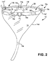
FIG. 2 is a perspective view of a collection bib and supporting rib ready to be placed in position on an air handler assembly for collecting cleaning fluid and debris during heat exchanger cleaning; -
FIG. 3 is a front elevation of the device ofFIG. 1 being moved into position on an air handler assembly, and the cord for holding the device in preliminary position; -
FIG. 4 is a front corner elevation of an air handler assembly showing a side mount bracket being moved into position between the air handler assembly and its supporting wall; -
FIG. 5 is a back corner elevation of an air handler assembly showing a bib supporting rib end being moved into position in a receptor slit in the lower portion of side mount bracket; -
FIG. 6 is a back corner elevation of an air handler assembly showing mounting bracket in position and threaded with supporting cord; -
FIG. 7 is an assembly view of apparatus of the invention including bib, rib, side brackets, and supporting cord with cord locks; and -
FIG. 8 is a modified embodiment of mounting bracket according to the invention. - Referring now to
FIGS. 1 through 8 , the apparatus and method of the invention have particular application to cleaning of a mini-splitair handler assembly 10 mounted on a wall W in a residence or an office leaving a space S betweenair handler assembly 10 and wall W along opposite rear side edges 10a-b of the air handler assembly. Mini-split air handler assemblies have a determinable range of width, height, and depth as can be judged from the installed unit shown inFIG. 1 of the drawing. The apparatus of the invention is adjustable in its design and construction to accommodate mini-split units sized in such determinable range. - Referring to
FIGS. 1-4 , adevice 12 for collection and disposal of waste cleaning fluid and debris from anair handler assembly 10 comprises generally apparatus including a collection bag orbib 14, anarcuate rib 16 for holding the bib open and mounting it in operating position, a pair of mountingbrackets 18a-b held in the space S betweenair handler assembly 10 and supporting wall W and receivable of the ends ofrib 16, a deflector plate D insertable along line L betweenair handler assembly 10 and wall W on the bottom side of the air handler assembly, and a supporting and retainingcord 20 with cord clamps 22 for holding bib and rib in position while the heat exchanger (not shown) ofair handler assembly 10 is cleaned. - The collection means comprises a large flexible impermeable
plastic bib 14 in the general shape of a funnel withlarge entry opening 14a withmarginal hem 14b to define arib 16 receivingpassage 14c, and aconical body 14d converging into an elongate duct 14e leading waste fluid and debris to a drain line or collection container such as a five gallon bucket or the like. The bib opening is hemmed 14b over a front arcuate portion of the opening to define arib receiving passage 14c open at eachend 14c', 14c". Arib 16 inserted intopassage 14c projects through each open end to expose rib end hooks 16a-b, andcord apertures 16c-d, seen best inFIG. 5 . - The
bib opening 14a includes aback margin 14f extending betweenhem openings 14c', 14c", the back margin being defined by aflap 14g ofbib 14 folded at the margin to define an elongateinside recess 14h within back bib face 14i and backflap 14g. The elongate recess accommodates a length of supportingcord 20 extending betweenrib end apertures 16c-d for the purpose of positioning and holding the bib backmargin 14f up and under an A/C unit along a line L (FIG. 3 ) where theunit underside 10c meets supporting wall W. - The
rib 16 is a slat preferably made of plastic that may be preformed, or may be flexible to form an opening mouth ofbib opening 14a to accommodate different mini-split air handler assemblies having different widths.Arcuate rib 16 is an elongated strip having ends terminating in ahook 16a-b and having acord aperture 16c-d. In one preferred embodiment, the rib passes throughbib hem 14b for spreading the open end of the bib beneath the coils of an air handler assembly. It is understood thatbib 14 andrib 16 be removably or permanently coupled using multiple known means including, but not limited to, snaps, buttons, Velcro, hooks, glue or fusion of the materials. The rib and hem have a pair of alignedcentral apertures cord 20. - As seen best in
FIG. 5 , each end ofrib 16 has anopening 16c-d for passing the supporting cord and anend hook 16a-b defined bytab 16f andadjacent slot 16g inrib end edge 16h-i.Tab 16f fits through aslit 18c in aside bracket 18a-b and the rib end is moved so thatrib slot 16g firmly engages slit 18c in side bracket wall. When each rib end hook is secured in a side bracket slit, the rib passes through the bib hem in desired arc across the front of the A/C unit holding the bib in wide open position. -
Side mount brackets 18a-b shown inFIGS. 4-6 are slipped into position in an existing space S between anair handler assembly 10 and the unit's supporting wall W. In a currently preferred embodiment, aside mounting bracket 18a-b comprises anelongate plate 18d having an axis x-x', side edges 18e-f, first and second ends 18g-h spaced from each other along the axis, at least a single integral flange 18i extending from a side edge at one end of the plate, and acrown 18j joined to flange and plate at the one end of the plate.Bracket plate 18d has at least one and preferably a plurality of ribhook receiving slits 18c.Bracket crown 18j has at least one and preferably twoopenings 18j' for passing supportingcord 20. - In another preferred embodiment shown in
FIG. 8 , aside mount bracket 28 comprises anelongate plate 28d having an axis x-x', side edges 28e-f, first and second ends 28g-h spaced from each other along the axis, anintegral flange 28i andcrown 28j at both ends extending in opposed directions from the axis, and a Z-shapedridge 28k includingcentral ridge 28k' along the axis andright angle ridges 28k" at both ends separating flange and crown. Two rows ofslits 28c extend axially of the plate on either side of central ridge, and the crown dualcord passing apertures 28j'. The preferred embodiment ofFIG. 8 comprises a single side bracket configuration that can be used on both the left and right sides 10a-b of an air handler assembly. The Z-shape ridge serves as a stop for limiting movement of the bracket into space S betweenair handler assembly 10 and supporting wall W so that the bracket exposes slits and openings and provides a necessary base for securing supportingcord 20. - In addition to providing anchorage for supporting
cord 20, in oneembodiment brackets 18a-b also may extend laterally along the wall in any desired shape or size to provide additional protection for the supporting wall against deflection, splashing, and damage by fluids and debris. - Supporting and retaining
cord 20 as shown inFIGS. 3 and7 passes through onerib center aperture 16e, through one or both apertures in first mountingbracket 18a, through firstrib end aperture 16c, through therecess 14h formed byback flap 14g of the bib, through secondrib end aperture 16d, through one or both apertures insecond mounting bracket 18b, and through the otherrib center aperture 16e. Supporting cord is drawn taut, with inside flap margin of the bib fetched up under deflector plate D in disposed in the air handler assembly joint with the supporting wall W, the rib end hooks 16f engaged inbracket slits 18c, the rib brought to a generally horizontal position, and cord clamps 22 applied oncord 20 at each rib end opening and each rib central opening to holddevice 12 firmly to A/C unit for heat exchanger cleaning. - It will be observed that supporting
cord 20 as it passes throughrib end apertures - In a further preferred embodiment, the flexible rib and bib are foldable to fit within a conventional storage and shipping container, e.g., a standard 5-gallon pail with lid. Preferably, the brackets, deflector plate, and supporting cord are also sized to fit within such a container. A 5-gallon pail is doubly useful as a receptacle for waste water and debris captured by the bib.
- In still a further preferred embodiment, the elongated duct 14e, of
bib 14, leading waste fluid and debris to a drain line or collection container, cooperates with a tube or hose to provide a means for removing the waste fluids and debris to a more distant receptacle. It is envisioned that the elongated duct 14e will rely upon known receptacles for linking to a hose or tube such as friction or male/female clamping or threaded fittings. In addition to such fittings and cooperating means, the elongated duct 14e preferably includes means for arresting the flow of fluids and debris, such as a clamp, spigot, or valve in the event of a receptacle's over-flow or clogging or the user's need to empty the storage and shipping container. - In practice, the device is prepared by assembling the rib in the bib hem, threading the supporting cord through one rib central aperture, one bracket crown aperture, one rib end aperture, the bib inner flap recess, through the other rib end aperture, the other bracket crown aperture, and the other rib central aperture, the rib ends being hooked onto the bracket slits, the cord being drawn tight to secure the bib in place with its horizontal opening level with the bottom of the air handler assembly, and the cord clamps cinched up to the rib to hold the device stationary while heat exchanger cleaning proceeds.
- A suitable supporting
cord 20 is an elastic cord popularly known as a bungee cord. Cord clamps 22 are also well-known and slide along the cord to a desired position where they are released. - A preferred method in accordance with the present invention comprises the steps of a) placing an impermeable
protective cover 30 on an air handler assemblyoperating control panel 32; b) inserting left andright side brackets 28 between the air handler assembly side edges and the supporting wall W; c) inserting the deflector plate D between the bottom of the air handler assembly and the supporting wall W; d) opening a funnelshape collection bib 14 with anarcuate rib 16; deploying the open bib by connecting the rib to each side bracket; f) passing the supporting cord through the front of the rib and bib, one side bracket, one end of the rib, through the bib underneath the air handler assembly, through the other rib end, through the other side bracket, and through the front of the rib and bib; h) sliding the bib recessH containing cord 20 upward along line L between wall W and deflector plate D; i) drawing the cord tight to support the bib in position below the air handler assembly; and j) clamping thecord 20 to the rib center and rib ends to hold the cord tight. - Various changes may be made to the structure embodying the principles of the invention. The foregoing embodiments are set forth in an illustrative and not in a limiting sense. The scope of the invention is defined by the claims appended hereto.
Claims (14)
- An apparatus 12 for collecting waste fluid and debris resulting from cleaning of an air conditioning air handler assembly 10 mounted on a supporting wall W, comprising:a) a collection bib 14 having an open first end 14a positionable adjacent said air handler assembly 10 for collecting said waste fluid and debris;b) a rib 16 cooperating with said collection bib 14 at said first end 14a to shape said first end for said collecting;c) at least one bracket 18 disposable between said air handler assembly 10 and said wall W;d) at least one deflector plate D disposable between said air handler assembly 10 and said wall W; ande) at least one support element 20 disposed between said rib 16 and said at least one bracket 18 to position said bib and said rib for said collecting;and wherein said collection bib 14 further comprises an open second end 14e for discharging said collected waste fluid and debris and characterised in that said open second end 14e comprises means for stopping flow of liquid through said open second end.
- An apparatus in accordance with Claim 1 wherein said discharged and collected waste fluid and debris are directed by said second end of said bib 14e to means for the safe collection and removal of fluid and debris from the work site selected from the group consisting of receptacle connected or cooperating with existing drain, reusable bucket, and disposable container.
- An apparatus in accordance with Claim 1 wherein said second end of said bib 14e for discharging said collected waste fluid and debris cooperates with a means for arresting the flow of fluids and debris or a tube or hose for the safe removal of fluid and debris from the work site.
- An apparatus in accordance with Claim 2 wherein said reusable bucket is sized for the easy storage and transportation of each of the claimed components of the apparatus by a single user to and from the work site.
- An apparatus in accordance with Claim 1 wherein said rib 16 is flexible, optionally compressible for easy storage and transportation to and from the worksite.
- An apparatus in accordance with Claim 1 wherein said rib 16 is fixedly or removably attached to said collection bib 14.
- An apparatus in accordance with Claim 1 wherein said rib 16 is disposed in a hem 14b formed along said open first end 14a.
- An apparatus in accordance with Claim 1 comprising a first and at least a second of said brackets 18,28, which optionally may be sized and shaped for easy storage and transportation to and from the worksite.
- An apparatus in accordance with Claim 8 wherein said first and second brackets 18,28 are disposable along opposing sides 10a,10b of said air handler assembly.
- An apparatus in accordance with Claim 8 wherein said brackets 18,28 are sized and shaped to provide added peripheral protection to said supporting wall W from fluids and debris.
- An apparatus in accordance with Claim 1 wherein said support element 20 is a flexible, elastic cord.
- An apparatus in accordance with Claim 1 further comprising at least one cord clamp 22 disposed on said support element 20 for limiting the operating length thereof.
- An apparatus 12 for collecting waste fluid and debris from the cleaning of an air conditioning air handler assembly 10 mounted on a supporting wall W, comprising:a) a collection bib 14 having an open first end 14a positionable adjacent and below said air conditioning air handler assembly 10 for collecting said waste fluid and debris therefrom, and having an open second end 14e for discharging said collected waste fluid and debris and comprising means for stopping flow of liquid through said open second end, and having a hem 14b extending partially around said open end, and having a back flap 14g forming a recess 14h in the non-hemmed portion of said open end 14e;b) a flexible rib 16 having first and second ends disposed through said hem 14b to shape said first end 14a for said collecting, said rib having first and second center apertures 16e and first and second end apertures 16c,16d and first and second hooks 16f formed at said first and second ends;c) a first side bracket 18,28 disposable between said air handler assembly 10 and said wall W along a first side 10a of said air handler assembly 10 and extending vertically thereby above and below, and having at least one aperture 18j', 28j', and having at least one slit 18c formed therein for receiving said first rib end hook 16f;d) a second side bracket 18,28 disposable between said air handler assembly 10 and said wall W along a second side 10b of said air handler assembly and extending vertically thereby above and below, and having at least one aperture 18j',28j', and having at least one slit 18c formed therein for receiving said second rib end hook 16f;e) at least one deflector plate D disposable between said air handler assembly 10 and said wall W along the bottom of said air handler assembly;f) a flexible cord 20 passing through one of said rib center apertures 16e, through said at least one aperture 18j',28j' in said first side bracket, through said first rib end aperture 16c, through said recess 14h, through said second rib end aperture 16d, through said at least one aperture in said second side bracket, and through the other of said rib center apertures 16e; andg) at least one cord clamp 22 disposed on said flexible cord 20 adjacent said first and second rib center apertures 16e.
- A method for collecting waste fluid and debris from the cleaning of an air conditioning air handler assembly 10 mounted on a supporting wall W, comprising the steps of:a) placing an impermeable protective cover 30 on an operating control panel 32 of said air handler assembly;b) inserting first and second side brackets 18,28 between said air handler assembly side edges 10a,10b and said supporting wall W;c) inserting a deflector plate D between the bottom of said air handler assembly and said supporting wall;d) opening a funnel shape collection bib 14 with an arcuate rib 16, wherein said collection bib 14 comprises an open second end 14e for discharging said collected waste fluid and debris and wherein said open second end 14e comprises means for stopping flow of liquid through said open second end;e) deploying said open bib 14 by connecting said rib 16 to each of said first and second side brackets 28;f) passing a supporting cord 20 through the front of said rib 16 and bib 14, a one of said first and second side brackets 28, one end of said rib 16, through said bib recess H underneath said air handler assembly, through the other end of said rib 16, through the other of said first and second side brackets 28, and through the front of said rib and said bib;g) sliding said bib recess H containing said cord 20 upward along line L between said wall W and said deflector plate D;h) drawing said supporting cord 20 tight to support said bib (14) in position below said air handler assembly 10; andi) clamping said supporting cord 20 at said rib center and said rib ends to hold said supporting cord tight.
Applications Claiming Priority (2)
| Application Number | Priority Date | Filing Date | Title |
|---|---|---|---|
| US14/690,414 US9259769B1 (en) | 2015-04-18 | 2015-04-18 | Apparatus and method for collection and disposal of cleaning waste-water and debris from air conditioners |
| PCT/US2016/028068 WO2016172028A1 (en) | 2015-04-18 | 2016-04-18 | Apparatus and method for collection disposal of cleaning waste-water and debris from air conditioners |
Publications (3)
| Publication Number | Publication Date |
|---|---|
| EP3286516A1 EP3286516A1 (en) | 2018-02-28 |
| EP3286516A4 EP3286516A4 (en) | 2018-11-21 |
| EP3286516B1 true EP3286516B1 (en) | 2021-09-08 |
Family
ID=55275278
Family Applications (1)
| Application Number | Title | Priority Date | Filing Date |
|---|---|---|---|
| EP16783642.8A Active EP3286516B1 (en) | 2015-04-18 | 2016-04-18 | Apparatus and method for collection disposal of cleaning waste-water and debris from air conditioners |
Country Status (8)
| Country | Link |
|---|---|
| US (1) | US9259769B1 (en) |
| EP (1) | EP3286516B1 (en) |
| CN (1) | CN107636414A (en) |
| AU (2) | AU2016252122B2 (en) |
| CA (1) | CA2983369C (en) |
| DK (1) | DK3286516T3 (en) |
| MX (1) | MX395313B (en) |
| WO (1) | WO2016172028A1 (en) |
Families Citing this family (12)
| Publication number | Priority date | Publication date | Assignee | Title |
|---|---|---|---|---|
| US10144628B1 (en) * | 2013-02-27 | 2018-12-04 | Crossford International, Llc | Apparatus and method for collection and disposal of waste-water and debris from air conditioners and other sources |
| JP6680087B2 (en) * | 2016-06-03 | 2020-04-15 | 三菱電機ビルテクノサービス株式会社 | Cleaning work auxiliary device |
| US10378780B2 (en) | 2017-01-24 | 2019-08-13 | The Air Center LLC | Apparatus and method for cleaning split system air conditioners |
| EP3425138B1 (en) * | 2017-07-06 | 2020-08-05 | Hermes Fassadenreinigung GmbH | Catching device for facade cleaning liquid |
| US10982915B2 (en) | 2018-07-17 | 2021-04-20 | Clean Coil Products Llc | Apparatus and method to facilitate collecting fluid from wall-mounted appliances |
| US11098907B1 (en) * | 2019-05-17 | 2021-08-24 | Grease Catcher Systems, LLC | Apparatus and method for containing and recovering residue from a kitchen ventilation system |
| CN110926260B (en) * | 2019-12-11 | 2025-01-10 | 北京燕山中海建筑安装有限公司 | High-pressure water cleaning waste recovery system |
| US20210293437A1 (en) * | 2020-02-27 | 2021-09-23 | Samson Assets Corporation | Air Conditioner System Switch Device |
| US10890354B1 (en) | 2020-10-09 | 2021-01-12 | Crossford International, Llc | System for facilitating the cleaning of a mini-split air handling unit |
| US11420221B2 (en) | 2020-10-30 | 2022-08-23 | Diversitech Corporation | Portable chemical sprayer system |
| US12535173B1 (en) * | 2023-03-18 | 2026-01-27 | Brendan J. Rabbett | Water containment apparatus |
| CN117515674B (en) * | 2023-12-04 | 2024-06-11 | 无锡雪鸥移动空调有限公司 | Non-drainage aircraft process guarantee mobile air conditioner |
Family Cites Families (3)
| Publication number | Priority date | Publication date | Assignee | Title |
|---|---|---|---|---|
| JPH09119797A (en) * | 1995-10-26 | 1997-05-06 | P C G Tekunika:Kk | Cleaning method for indoor unit of air conditioner and capturing instrument for cleaning emission matter |
| US6863116B1 (en) | 2004-04-01 | 2005-03-08 | Goodway Technologies Corporation | Apparatus and method for collection and disposal of waste-water and debris from heat exchanger tubes and other sources |
| WO2012100282A1 (en) * | 2011-01-28 | 2012-08-02 | Pizzey Robert John | Cleaning indoor wall hung fan/coil units |
-
2015
- 2015-04-18 US US14/690,414 patent/US9259769B1/en active Active
-
2016
- 2016-04-18 CN CN201680034040.5A patent/CN107636414A/en active Pending
- 2016-04-18 EP EP16783642.8A patent/EP3286516B1/en active Active
- 2016-04-18 DK DK16783642.8T patent/DK3286516T3/en active
- 2016-04-18 MX MX2017013269A patent/MX395313B/en unknown
- 2016-04-18 WO PCT/US2016/028068 patent/WO2016172028A1/en not_active Ceased
- 2016-04-18 AU AU2016252122A patent/AU2016252122B2/en active Active
- 2016-04-18 CA CA2983369A patent/CA2983369C/en active Active
-
2021
- 2021-04-27 AU AU2021202606A patent/AU2021202606B2/en active Active
Also Published As
| Publication number | Publication date |
|---|---|
| EP3286516A4 (en) | 2018-11-21 |
| US9259769B1 (en) | 2016-02-16 |
| DK3286516T3 (en) | 2021-11-08 |
| CN107636414A (en) | 2018-01-26 |
| AU2021202606A1 (en) | 2021-05-27 |
| CA2983369C (en) | 2019-01-08 |
| MX2017013269A (en) | 2018-08-15 |
| AU2016252122B2 (en) | 2021-01-28 |
| AU2021202606B2 (en) | 2023-07-20 |
| AU2016252122A1 (en) | 2017-11-02 |
| WO2016172028A1 (en) | 2016-10-27 |
| CA2983369A1 (en) | 2016-10-27 |
| MX395313B (en) | 2025-03-19 |
| EP3286516A1 (en) | 2018-02-28 |
Similar Documents
| Publication | Publication Date | Title |
|---|---|---|
| AU2021202606B2 (en) | Apparatus and method for collection disposal of cleaning waste-water and debris from air conditioners | |
| US10144628B1 (en) | Apparatus and method for collection and disposal of waste-water and debris from air conditioners and other sources | |
| US3125869A (en) | Ventilating apparatus | |
| EP1876396B1 (en) | Air conditioner | |
| US6195910B1 (en) | Device for coupling an exhaust tube to an exhaust port | |
| US20230126498A1 (en) | Adjustable top cover for split-system hvac units | |
| CN100561059C (en) | air conditioner | |
| US5152154A (en) | Fan coil unit | |
| CN107543298A (en) | Air conditioner | |
| KR20190095201A (en) | Shielding membrane for high pressure cleaning | |
| US10890354B1 (en) | System for facilitating the cleaning of a mini-split air handling unit | |
| US20230130691A1 (en) | Baffle strainer system and method | |
| EP1876397A2 (en) | Air conditioner with condensate collection via drain pans and evaporative cooling of heat exchanger | |
| CN206176696U (en) | Filter screen device and air conditioning equipment | |
| US10982915B2 (en) | Apparatus and method to facilitate collecting fluid from wall-mounted appliances | |
| CN208804868U (en) | The heat-exchanging component and air conditioner of air conditioner | |
| CN111765532A (en) | an air conditioner | |
| KR102269763B1 (en) | stand type air conditioning cleaning device | |
| CN214536555U (en) | Air conditioner | |
| US20170144098A1 (en) | Air Handler Cleaning Receptacle | |
| KR102267418B1 (en) | cleaning adapter for ventilation diffuser | |
| KR101515949B1 (en) | Outdoor unit of air conditioner | |
| CN112781114B (en) | Air Conditioner | |
| JPH11223380A (en) | Indoor unit of air conditioner and method of handling heat exchanger in indoor unit | |
| CN107208925A (en) | A kind of recycling system of air conditioning condensed water |
Legal Events
| Date | Code | Title | Description |
|---|---|---|---|
| STAA | Information on the status of an ep patent application or granted ep patent |
Free format text: STATUS: THE INTERNATIONAL PUBLICATION HAS BEEN MADE |
|
| PUAI | Public reference made under article 153(3) epc to a published international application that has entered the european phase |
Free format text: ORIGINAL CODE: 0009012 |
|
| STAA | Information on the status of an ep patent application or granted ep patent |
Free format text: STATUS: REQUEST FOR EXAMINATION WAS MADE |
|
| 17P | Request for examination filed |
Effective date: 20171017 |
|
| AK | Designated contracting states |
Kind code of ref document: A1 Designated state(s): AL AT BE BG CH CY CZ DE DK EE ES FI FR GB GR HR HU IE IS IT LI LT LU LV MC MK MT NL NO PL PT RO RS SE SI SK SM TR |
|
| AX | Request for extension of the european patent |
Extension state: BA ME |
|
| DAV | Request for validation of the european patent (deleted) | ||
| DAX | Request for extension of the european patent (deleted) | ||
| A4 | Supplementary search report drawn up and despatched |
Effective date: 20181018 |
|
| RIC1 | Information provided on ipc code assigned before grant |
Ipc: F28G 15/02 20060101AFI20181012BHEP |
|
| GRAP | Despatch of communication of intention to grant a patent |
Free format text: ORIGINAL CODE: EPIDOSNIGR1 |
|
| STAA | Information on the status of an ep patent application or granted ep patent |
Free format text: STATUS: GRANT OF PATENT IS INTENDED |
|
| INTG | Intention to grant announced |
Effective date: 20200707 |
|
| GRAJ | Information related to disapproval of communication of intention to grant by the applicant or resumption of examination proceedings by the epo deleted |
Free format text: ORIGINAL CODE: EPIDOSDIGR1 |
|
| STAA | Information on the status of an ep patent application or granted ep patent |
Free format text: STATUS: REQUEST FOR EXAMINATION WAS MADE |
|
| GRAP | Despatch of communication of intention to grant a patent |
Free format text: ORIGINAL CODE: EPIDOSNIGR1 |
|
| STAA | Information on the status of an ep patent application or granted ep patent |
Free format text: STATUS: GRANT OF PATENT IS INTENDED |
|
| INTC | Intention to grant announced (deleted) | ||
| INTG | Intention to grant announced |
Effective date: 20201221 |
|
| GRAS | Grant fee paid |
Free format text: ORIGINAL CODE: EPIDOSNIGR3 |
|
| GRAF | Information related to payment of grant fee modified |
Free format text: ORIGINAL CODE: EPIDOSCIGR3 |
|
| GRAA | (expected) grant |
Free format text: ORIGINAL CODE: 0009210 |
|
| STAA | Information on the status of an ep patent application or granted ep patent |
Free format text: STATUS: THE PATENT HAS BEEN GRANTED |
|
| AK | Designated contracting states |
Kind code of ref document: B1 Designated state(s): AL AT BE BG CH CY CZ DE DK EE ES FI FR GB GR HR HU IE IS IT LI LT LU LV MC MK MT NL NO PL PT RO RS SE SI SK SM TR |
|
| RAP1 | Party data changed (applicant data changed or rights of an application transferred) |
Owner name: DIVERSITECH CORPORATION |
|
| REG | Reference to a national code |
Ref country code: GB Ref legal event code: FG4D |
|
| RIN1 | Information on inventor provided before grant (corrected) |
Inventor name: CACKOWSKI, SCOTT C. Inventor name: HARDY, MICHAEL Inventor name: KANE, TIMOTHY |
|
| REG | Reference to a national code |
Ref country code: CH Ref legal event code: EP Ref country code: AT Ref legal event code: REF Ref document number: 1428948 Country of ref document: AT Kind code of ref document: T Effective date: 20210915 |
|
| REG | Reference to a national code |
Ref country code: DE Ref legal event code: R096 Ref document number: 602016063473 Country of ref document: DE |
|
| REG | Reference to a national code |
Ref country code: IE Ref legal event code: FG4D |
|
| REG | Reference to a national code |
Ref country code: DK Ref legal event code: T3 Effective date: 20211104 |
|
| REG | Reference to a national code |
Ref country code: SE Ref legal event code: TRGR |
|
| REG | Reference to a national code |
Ref country code: NL Ref legal event code: FP |
|
| REG | Reference to a national code |
Ref country code: LT Ref legal event code: MG9D |
|
| PG25 | Lapsed in a contracting state [announced via postgrant information from national office to epo] |
Ref country code: RS Free format text: LAPSE BECAUSE OF FAILURE TO SUBMIT A TRANSLATION OF THE DESCRIPTION OR TO PAY THE FEE WITHIN THE PRESCRIBED TIME-LIMIT Effective date: 20210908 Ref country code: NO Free format text: LAPSE BECAUSE OF FAILURE TO SUBMIT A TRANSLATION OF THE DESCRIPTION OR TO PAY THE FEE WITHIN THE PRESCRIBED TIME-LIMIT Effective date: 20211208 Ref country code: ES Free format text: LAPSE BECAUSE OF FAILURE TO SUBMIT A TRANSLATION OF THE DESCRIPTION OR TO PAY THE FEE WITHIN THE PRESCRIBED TIME-LIMIT Effective date: 20210908 Ref country code: FI Free format text: LAPSE BECAUSE OF FAILURE TO SUBMIT A TRANSLATION OF THE DESCRIPTION OR TO PAY THE FEE WITHIN THE PRESCRIBED TIME-LIMIT Effective date: 20210908 Ref country code: HR Free format text: LAPSE BECAUSE OF FAILURE TO SUBMIT A TRANSLATION OF THE DESCRIPTION OR TO PAY THE FEE WITHIN THE PRESCRIBED TIME-LIMIT Effective date: 20210908 Ref country code: LT Free format text: LAPSE BECAUSE OF FAILURE TO SUBMIT A TRANSLATION OF THE DESCRIPTION OR TO PAY THE FEE WITHIN THE PRESCRIBED TIME-LIMIT Effective date: 20210908 Ref country code: BG Free format text: LAPSE BECAUSE OF FAILURE TO SUBMIT A TRANSLATION OF THE DESCRIPTION OR TO PAY THE FEE WITHIN THE PRESCRIBED TIME-LIMIT Effective date: 20211208 |
|
| PG25 | Lapsed in a contracting state [announced via postgrant information from national office to epo] |
Ref country code: LV Free format text: LAPSE BECAUSE OF FAILURE TO SUBMIT A TRANSLATION OF THE DESCRIPTION OR TO PAY THE FEE WITHIN THE PRESCRIBED TIME-LIMIT Effective date: 20210908 Ref country code: GR Free format text: LAPSE BECAUSE OF FAILURE TO SUBMIT A TRANSLATION OF THE DESCRIPTION OR TO PAY THE FEE WITHIN THE PRESCRIBED TIME-LIMIT Effective date: 20211209 |
|
| PG25 | Lapsed in a contracting state [announced via postgrant information from national office to epo] |
Ref country code: IS Free format text: LAPSE BECAUSE OF FAILURE TO SUBMIT A TRANSLATION OF THE DESCRIPTION OR TO PAY THE FEE WITHIN THE PRESCRIBED TIME-LIMIT Effective date: 20220108 Ref country code: SM Free format text: LAPSE BECAUSE OF FAILURE TO SUBMIT A TRANSLATION OF THE DESCRIPTION OR TO PAY THE FEE WITHIN THE PRESCRIBED TIME-LIMIT Effective date: 20210908 Ref country code: SK Free format text: LAPSE BECAUSE OF FAILURE TO SUBMIT A TRANSLATION OF THE DESCRIPTION OR TO PAY THE FEE WITHIN THE PRESCRIBED TIME-LIMIT Effective date: 20210908 Ref country code: RO Free format text: LAPSE BECAUSE OF FAILURE TO SUBMIT A TRANSLATION OF THE DESCRIPTION OR TO PAY THE FEE WITHIN THE PRESCRIBED TIME-LIMIT Effective date: 20210908 Ref country code: PT Free format text: LAPSE BECAUSE OF FAILURE TO SUBMIT A TRANSLATION OF THE DESCRIPTION OR TO PAY THE FEE WITHIN THE PRESCRIBED TIME-LIMIT Effective date: 20220110 Ref country code: PL Free format text: LAPSE BECAUSE OF FAILURE TO SUBMIT A TRANSLATION OF THE DESCRIPTION OR TO PAY THE FEE WITHIN THE PRESCRIBED TIME-LIMIT Effective date: 20210908 Ref country code: EE Free format text: LAPSE BECAUSE OF FAILURE TO SUBMIT A TRANSLATION OF THE DESCRIPTION OR TO PAY THE FEE WITHIN THE PRESCRIBED TIME-LIMIT Effective date: 20210908 Ref country code: CZ Free format text: LAPSE BECAUSE OF FAILURE TO SUBMIT A TRANSLATION OF THE DESCRIPTION OR TO PAY THE FEE WITHIN THE PRESCRIBED TIME-LIMIT Effective date: 20210908 Ref country code: AL Free format text: LAPSE BECAUSE OF FAILURE TO SUBMIT A TRANSLATION OF THE DESCRIPTION OR TO PAY THE FEE WITHIN THE PRESCRIBED TIME-LIMIT Effective date: 20210908 |
|
| REG | Reference to a national code |
Ref country code: DE Ref legal event code: R097 Ref document number: 602016063473 Country of ref document: DE |
|
| PLBE | No opposition filed within time limit |
Free format text: ORIGINAL CODE: 0009261 |
|
| STAA | Information on the status of an ep patent application or granted ep patent |
Free format text: STATUS: NO OPPOSITION FILED WITHIN TIME LIMIT |
|
| 26N | No opposition filed |
Effective date: 20220609 |
|
| PG25 | Lapsed in a contracting state [announced via postgrant information from national office to epo] |
Ref country code: SI Free format text: LAPSE BECAUSE OF FAILURE TO SUBMIT A TRANSLATION OF THE DESCRIPTION OR TO PAY THE FEE WITHIN THE PRESCRIBED TIME-LIMIT Effective date: 20210908 |
|
| REG | Reference to a national code |
Ref country code: CH Ref legal event code: PL |
|
| GBPC | Gb: european patent ceased through non-payment of renewal fee |
Effective date: 20220418 |
|
| PG25 | Lapsed in a contracting state [announced via postgrant information from national office to epo] |
Ref country code: MC Free format text: LAPSE BECAUSE OF FAILURE TO SUBMIT A TRANSLATION OF THE DESCRIPTION OR TO PAY THE FEE WITHIN THE PRESCRIBED TIME-LIMIT Effective date: 20210908 Ref country code: LU Free format text: LAPSE BECAUSE OF NON-PAYMENT OF DUE FEES Effective date: 20220418 Ref country code: LI Free format text: LAPSE BECAUSE OF NON-PAYMENT OF DUE FEES Effective date: 20220430 Ref country code: IT Free format text: LAPSE BECAUSE OF FAILURE TO SUBMIT A TRANSLATION OF THE DESCRIPTION OR TO PAY THE FEE WITHIN THE PRESCRIBED TIME-LIMIT Effective date: 20210908 Ref country code: GB Free format text: LAPSE BECAUSE OF NON-PAYMENT OF DUE FEES Effective date: 20220418 Ref country code: CH Free format text: LAPSE BECAUSE OF NON-PAYMENT OF DUE FEES Effective date: 20220430 |
|
| REG | Reference to a national code |
Ref country code: AT Ref legal event code: UEP Ref document number: 1428948 Country of ref document: AT Kind code of ref document: T Effective date: 20210908 |
|
| PGFP | Annual fee paid to national office [announced via postgrant information from national office to epo] |
Ref country code: DK Payment date: 20230427 Year of fee payment: 8 |
|
| P01 | Opt-out of the competence of the unified patent court (upc) registered |
Effective date: 20230630 |
|
| PG25 | Lapsed in a contracting state [announced via postgrant information from national office to epo] |
Ref country code: HU Free format text: LAPSE BECAUSE OF FAILURE TO SUBMIT A TRANSLATION OF THE DESCRIPTION OR TO PAY THE FEE WITHIN THE PRESCRIBED TIME-LIMIT; INVALID AB INITIO Effective date: 20160418 |
|
| PGFP | Annual fee paid to national office [announced via postgrant information from national office to epo] |
Ref country code: IE Payment date: 20240223 Year of fee payment: 9 Ref country code: NL Payment date: 20240226 Year of fee payment: 9 |
|
| PG25 | Lapsed in a contracting state [announced via postgrant information from national office to epo] |
Ref country code: MK Free format text: LAPSE BECAUSE OF FAILURE TO SUBMIT A TRANSLATION OF THE DESCRIPTION OR TO PAY THE FEE WITHIN THE PRESCRIBED TIME-LIMIT Effective date: 20210908 Ref country code: CY Free format text: LAPSE BECAUSE OF FAILURE TO SUBMIT A TRANSLATION OF THE DESCRIPTION OR TO PAY THE FEE WITHIN THE PRESCRIBED TIME-LIMIT Effective date: 20210908 |
|
| PGFP | Annual fee paid to national office [announced via postgrant information from national office to epo] |
Ref country code: SE Payment date: 20240226 Year of fee payment: 9 |
|
| PGFP | Annual fee paid to national office [announced via postgrant information from national office to epo] |
Ref country code: AT Payment date: 20240326 Year of fee payment: 9 |
|
| PG25 | Lapsed in a contracting state [announced via postgrant information from national office to epo] |
Ref country code: MT Free format text: LAPSE BECAUSE OF FAILURE TO SUBMIT A TRANSLATION OF THE DESCRIPTION OR TO PAY THE FEE WITHIN THE PRESCRIBED TIME-LIMIT Effective date: 20210908 |
|
| REG | Reference to a national code |
Ref country code: DK Ref legal event code: EBP Effective date: 20240430 |
|
| PG25 | Lapsed in a contracting state [announced via postgrant information from national office to epo] |
Ref country code: DK Free format text: LAPSE BECAUSE OF NON-PAYMENT OF DUE FEES Effective date: 20240430 |
|
| PGFP | Annual fee paid to national office [announced via postgrant information from national office to epo] |
Ref country code: DE Payment date: 20250218 Year of fee payment: 10 |
|
| REG | Reference to a national code |
Ref country code: SE Ref legal event code: EUG |
|
| REG | Reference to a national code |
Ref country code: NL Ref legal event code: MM Effective date: 20250501 |
|
| PG25 | Lapsed in a contracting state [announced via postgrant information from national office to epo] |
Ref country code: TR Free format text: LAPSE BECAUSE OF FAILURE TO SUBMIT A TRANSLATION OF THE DESCRIPTION OR TO PAY THE FEE WITHIN THE PRESCRIBED TIME-LIMIT Effective date: 20210908 |
|
| REG | Reference to a national code |
Ref country code: AT Ref legal event code: MM01 Ref document number: 1428948 Country of ref document: AT Kind code of ref document: T Effective date: 20250418 |
|
| PG25 | Lapsed in a contracting state [announced via postgrant information from national office to epo] |
Ref country code: AT Free format text: LAPSE BECAUSE OF NON-PAYMENT OF DUE FEES Effective date: 20250418 |
|
| PG25 | Lapsed in a contracting state [announced via postgrant information from national office to epo] |
Ref country code: NL Free format text: LAPSE BECAUSE OF NON-PAYMENT OF DUE FEES Effective date: 20250501 |
|
| PG25 | Lapsed in a contracting state [announced via postgrant information from national office to epo] |
Ref country code: SE Free format text: LAPSE BECAUSE OF NON-PAYMENT OF DUE FEES Effective date: 20250419 |
|
| PG25 | Lapsed in a contracting state [announced via postgrant information from national office to epo] |
Ref country code: IE Free format text: LAPSE BECAUSE OF NON-PAYMENT OF DUE FEES Effective date: 20250418 |
|
| PGFP | Annual fee paid to national office [announced via postgrant information from national office to epo] |
Ref country code: BE Payment date: 20260317 Year of fee payment: 11 |
|
| PGFP | Annual fee paid to national office [announced via postgrant information from national office to epo] |
Ref country code: FR Payment date: 20260223 Year of fee payment: 11 |