EP3286366B1 - Device equipped with pattern-controlled components and textile machine comprising such a device - Google Patents
Device equipped with pattern-controlled components and textile machine comprising such a device Download PDFInfo
- Publication number
- EP3286366B1 EP3286366B1 EP16725915.9A EP16725915A EP3286366B1 EP 3286366 B1 EP3286366 B1 EP 3286366B1 EP 16725915 A EP16725915 A EP 16725915A EP 3286366 B1 EP3286366 B1 EP 3286366B1
- Authority
- EP
- European Patent Office
- Prior art keywords
- actuators
- actuator
- pattern
- actuator module
- cooling circuit
- Prior art date
- Legal status (The legal status is an assumption and is not a legal conclusion. Google has not performed a legal analysis and makes no representation as to the accuracy of the status listed.)
- Active
Links
Images



Classifications
-
- D—TEXTILES; PAPER
- D03—WEAVING
- D03C—SHEDDING MECHANISMS; PATTERN CARDS OR CHAINS; PUNCHING OF CARDS; DESIGNING PATTERNS
- D03C13/00—Shedding mechanisms not otherwise provided for
- D03C13/02—Shedding mechanisms not otherwise provided for with independent drive motors
- D03C13/025—Shedding mechanisms not otherwise provided for with independent drive motors with independent frame drives
-
- D—TEXTILES; PAPER
- D03—WEAVING
- D03C—SHEDDING MECHANISMS; PATTERN CARDS OR CHAINS; PUNCHING OF CARDS; DESIGNING PATTERNS
- D03C3/00—Jacquards
- D03C3/20—Electrically-operated jacquards
- D03C3/205—Independently actuated lifting cords
-
- D—TEXTILES; PAPER
- D03—WEAVING
- D03D—WOVEN FABRICS; METHODS OF WEAVING; LOOMS
- D03D39/00—Pile-fabric looms
- D03D39/02—Axminster looms, i.e. wherein pile tufts are inserted during weaving
-
- D—TEXTILES; PAPER
- D03—WEAVING
- D03J—AUXILIARY WEAVING APPARATUS; WEAVERS' TOOLS; SHUTTLES
- D03J1/00—Auxiliary apparatus combined with or associated with looms
- D03J1/008—Cooling systems
-
- D—TEXTILES; PAPER
- D05—SEWING; EMBROIDERING; TUFTING
- D05C—EMBROIDERING; TUFTING
- D05C15/00—Making pile fabrics or articles having similar surface features by inserting loops into a base material
- D05C15/04—Tufting
- D05C15/08—Tufting machines
- D05C15/26—Tufting machines with provision for producing patterns
Definitions
- This invention relates to a device equipped with pattern-controlled components for pattern-controlled feeding and/or selection of yarn for a textile machine comprising a plurality of actuators and a cooling circuit through which cooling liquid is flowable for the cooling of the actuators.
- This invention also relates to a Jacquard machine comprising such a device.
- this invention relates to a textile machine comprising such a device.
- Such a textile machine can, for example, be a tufting machine, or a weaving machine, which more specifically can be an Axminster weaving machine.
- Pattern-controlled components known as "pile feeders" are provided to feed the yarn pattern driven to the tufting needles.
- Other pattern-controlled components such as pattern-controlled components that control the hooks under the tuft fabric, with or without knives, are provided to determine the pattern-controlled selection of the pile height and/or pile form, namely pile loops or cut pile.
- Further pattern-controlled components which control the tufting needles directly are provided for the pattern-controlled selection of the yarn to be brought into a base fabric.
- a Jacquard machine is equipped with a very large number of pattern-controlled components for pattern-controlled positioning of the yarn.
- a weaving machine can comprise a Jacquard machine.
- a weaving machine can also be equipped with pattern-controlled components provided to feed the yarn pattern driven in order in this way to determine the pile height of the piles in the carpet.
- the pattern-controlled components can be provided for pattern-controlled selection of the yarn to be brought into a fabric.
- Such an Axminster weaving machine then comprises an Axminster Jacquard machine with such pattern-controlled components provided for pattern-controlled selection of the yarn.
- the actuators used here can be rotary motors, linear motors, stepper motors, voice-coil actuators, hydraulic or pneumatic actuators, solenoids, etc.
- US 6,807,917 B1 describes an example of such a device with yarn feeding modules for feeding yarn into a tufting machine in which the motors are air-cooled. Here a series of fans direct the necessary air over the components to be cooled.
- US 6,058,983 A describes a device wherein actuators for the vertical control of harness threads of a weaving mechanism are air-cooled. Air as a coolant is less effective, however, than other known cooling fluids. In the area around textile machines, the ambient air is warm and dusty so that filters are necessary to remove the dust from the air. Another possibility is to use outside air as cooling air, but this solution requires additional air pipes. Furthermore, in both cases a large contact area is necessary between the actuators and the air in order to be able to dissipate sufficient heat, and a relatively large flow of air is necessary in order to be able to cool the actuators sufficiently.
- the failure percentage of the actuators is relatively limited there and the risks of an interruption of the cooling circuit are more limited there, since the actuators are installed outside the actual working area.
- this invention relates in which dozens, hundreds or even thousands of actuators are installed in a more limited area in the immediate vicinity of the actual working area of the textile machine, and then predominantly above it, however, such water-cooled actuators are barely employed in practice. Due to the large number of actuators, there is a real chance of failure of one of the actuators, and furthermore the risks of consequential damage from the interruption of a water-filled cooling circuit cannot be neglected.
- This object of the invention is achieved by providing a device equipped with pattern-controlled components for pattern-controlled feeding and/or selection of yarn for a textile machine, comprising:
- the replacement of one or more of the actuators is less burdensome and less hazardous than with the known water-cooled actuators in which the cooling circuit runs through these actuators themselves or in which risk of a leak is greater.
- dust-free cooling is now achieved that is also far more efficient.
- the energy losses from the actuators in the form of residual heat can be discharged with a device according to the invention in a simple, operationally safe and efficient manner.
- the cooling of the actuators ensures that the actuators and the connected components can operate in a more limited temperature range and hence can be more appropriately dimensioned or that the operational safety of the actuators and the connected components is increased.
- At least partially integrating the cooling circuit in such a device into the mounting frame allows compact installation of the cooling circuit in the device. In this way the device can either be designed more compactly, or the components of the device can be installed less closely together within the same volume.
- the actuators can thus be made more easily attachable to the mounting frame without obstruction from the additional pipework forming the cooling circuit at the points where this cooling circuit is integrated into the mounting frame or in their immediate vicinity.
- the attachment elements for attaching the actuators to the mounting frame can thus be given the additional function of discharging the heat from the actuators to the cooling circuit.
- a cooling circuit can be provided for each mounting frame of a device according to this invention.
- a cooling circuit of a device according to this invention can also be installed spread across several mounting frames. The cooling circuit can run through the mounting frames in series or in parallel. It is thus possible, for example, to install one cooling circuit for two mounting frames.
- Each actuator module preferably comprises one or more thermally conductive elements to conduct heat from the actuators to the cooling circuit.
- each actuator module is preferably detachably installable in the device by means of the one or more thermally conductive elements.
- thermally conductive elements can provide optimum transfer of the heat.
- the use of such thermally conductive elements for installation of each actuator allows the number of installation elements required for the installation of each actuator in the device to be limited.
- each actuator is preferably installed at least partially separate from the one or more thermally conductive elements. At least one part of each actuator does not border on these one or more thermally conductive elements so that each actuator is not surrounded by these one or more thermally conductive elements. This also allows material to be saved because not all sides of the actuator modules have to be covered by such thermally conductive elements.
- each actuator is hereby preferably installed facing away from the one or more thermally conductive elements. More preferably, each actuator borders on the one or more thermally conductive elements on only one side.
- each actuator module can comprise a thermally conductive plate as said thermally conductive element.
- a thermally conductive plate can ensure a good heat transfer in combination with a simple installation.
- This thermally conductive plate can extend, for example, like a flange relative to each actuator of the actuator module. It can thereby extend like a flange relative to the head of such an actuator.
- thermally conductive elements comprise such a thermally conductive plate
- this thermally conductive plate is preferably detachably fastenable to a said beam through which cooling liquid is flowable for the detachable fastening of the actuator module to this beam.
- this beam can then advantageously form part of the mounting frame.
- each actuator module in a specific embodiment of a device according to this invention which comprises a said mounting frame and the one or more said actuator modules has a guide rib or guide slot and the mounting frame comprises a corresponding guide slot or guide rib to guide the actuator module during installation of said module.
- a special embodiment of a device according to this invention comprises one or more electrical components, whereby the cooling circuit is provided for cooling these electrical components.
- These electrical components can comprise i.a. PCBs, electronic circuits, processors, inverters, relays, etc.
- each actuator module preferably comprises one or more said electrical components.
- these electrical components could also be installed separately from these actuator modules in the device, whereby the actuator modules are installed detachably relative to these electrical components. All said electrical components are preferably contained in the one or more actuator modules. It is also possible to include part of the electrical components in the one or more actuator modules and to install the other part separately from these actuator modules in the device.
- each actuator module comprises one or more said electrical components
- the actuators of each actuator module are preferably installed on both sides of the electrical components of this actuator module.
- each actuator module comprises eight said actuators, four installed on each side of the electrical components.
- a device with one or more said electrical components comprises a said thermally conductive plate in each actuator module, then the actuators and the electrical components in each actuator module are preferably fastened to this thermally conductive plate.
- the cooling liquid in a preferred device according to this invention can be water or a water-based liquid.
- This invention also relates to a Jacquard machine comprising a device equipped with pattern-controlled components, whereby this device is a device according to this invention as described above, provided for pattern-controlled positioning of yarn.
- this invention relates to a textile machine comprising a device equipped with pattern-controlled components, whereby this device is a device according to this invention as described above.
- Such a textile machine according to this invention can, for example, be a tufting machine, an Axminster weaving machine or a weaving machine. Such a weaving machine can then more specifically comprise a said Jacquard machine according to this invention.
- the cooling circuit is furthermore preferably provided for the cooling of one or more mechanical parts of the device and/or of other mechanical and/or electrical parts of this textile machine.
- the figures illustrate a yarn feeding unit (1) for a tufting machine with pattern-controlled components (2) for the pattern-controlled feeding of yarn.
- a yarn feeding unit (1) for a tufting machine with pattern-controlled components (2) for the pattern-controlled feeding of yarn For a person skilled in the art it is clear from this how, by analogy, he can for example devise a yarn feeding unit for a weaving machine for the pattern-controlled feeding of yarn or how, by analogy, he can devise a selection unit for a tufting machine or weaving machine with pattern-controlled components for pattern-controlled selection of yarn.
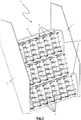
- the illustrated yarn feeding unit (1) comprises a mounting frame (3, 8) to which various yarn feeding modules (6) are detachably fastened.
- the mounting frame (3, 8) comprises two side walls (3) between which a number of beams (8) are installed more or less parallel to each other.
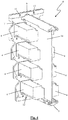
- the beams (8) are hollow and are connected together by pipes (5) to form together a cooling circuit (5, 8) through which water is flowable. In this way this cooling circuit (5, 8) is partially integrated into the mounting frame (3, 8).
- FIGS 4-6 show a separate yarn feeding module (6).
- Each yarn feeding module (6) comprises eight servomotors (4) that are mounted together on a plate (7).
- Four of these motors (4) are installed on each side of an electric circuit (10) which comprises i.a. the electronic components for controlling the servomotors (4).
- This electrical circuit (10) is also mounted on the said plate (7).
- the servomotors (4) are provided in a known manner to control pattern-controlled components (2) for the feeding of yarn for a tufting machine. As this is state-of-the-art and does not form part of the invention, this is not discussed in further detail here.
- the servomotors can be replaced by pneumatic actuators.
- the servomotors can, for example, be typically replaced by rotary or linear stepper motors.
- the servomotors can, for example, be typically replaced by solenoids.
- different numbers of actuators (4) per actuator module (6) may be desired.
- each yarn feeding module (6) is attachable to the beam (8) of the mounting frame (3, 8).
- this plate (7) has screw holes (12) at top and bottom through which screws can be inserted to screw this plate (7) to respective beams (8) of the mounting frame (3, 8).
- the beams (8) of the mounting frame (3, 8) have a stop (11) with which the upper side of the plate (7) can be aligned for simple positioning of the yarn feeding modules (6) relative to the beams (8) before it is screwed tight.
- This plate (7) is thermally conductive in order to be able to dissipate the heat of the motors (4) and the electric circuit (10) to the beams (8) which form part of the cooling circuit (5, 8) through which water is flowable.
- each yarn feeding module (6) comprises a guide rib (9) that can engage and slide in a corresponding guide slot (not illustrated) in the beams (8) in order to guide the yarn feeding module (6) relative to the beams (8) during installation in the yarn feeding unit (1).
- the yarn feeding modules (6) are located completely alongside the cooling circuit (5, 8) in the yarn feeding unit (1) and are detachable from the cooling circuit (5, 8) without having to interrupt this cooling circuit (5, 8).
- the illustrated cooling circuit (5, 8) is provided here for cooling both the motors (4) and the electric circuits (10) of the yarn feeding modules (6). Due to the thermally conductive plates (7), maximum heat from the motors (4) and the electric circuits (10) is discharged to the cooling circuit (5, 8).
- This cooling circuit (5, 8) can also be provided for the cooling of one or more mechanical parts of the device (1) and/or of other mechanical and/or electrical parts of the textile machine in which this device (1) is installed.
Landscapes
- Engineering & Computer Science (AREA)
- Textile Engineering (AREA)
- Treatment Of Fiber Materials (AREA)
- Cooling Or The Like Of Electrical Apparatus (AREA)
- Looms (AREA)
- Knitting Machines (AREA)
Description
- This invention relates to a device equipped with pattern-controlled components for pattern-controlled feeding and/or selection of yarn for a textile machine comprising a plurality of actuators and a cooling circuit through which cooling liquid is flowable for the cooling of the actuators.
This invention also relates to a Jacquard machine comprising such a device. Furthermore this invention relates to a textile machine comprising such a device. Such a textile machine can, for example, be a tufting machine, or a weaving machine, which more specifically can be an Axminster weaving machine. - Applications with devices to which this invention relates are known in various types of textile machine. Precise and delicate patterns and figures are becoming more and more in demand in the production of fabrics and/or carpets. The yarns are sub-divided into ever smaller groups and are together fed and/or selected by a pattern-controlled component in order to obtain the desired result in the fabric and/or carpet. The yarns are even being increasingly individually controlled and/or selected. This leads to a sharp increase in the number of actuators used.
- Different versions of such pattern-controlled components can be found in tufting machines. Pattern-controlled components known as "pile feeders" are provided to feed the yarn pattern driven to the tufting needles. Other pattern-controlled components such as pattern-controlled components that control the hooks under the tuft fabric, with or without knives, are provided to determine the pattern-controlled selection of the pile height and/or pile form, namely pile loops or cut pile. Further pattern-controlled components which control the tufting needles directly are provided for the pattern-controlled selection of the yarn to be brought into a base fabric.
A Jacquard machine is equipped with a very large number of pattern-controlled components for pattern-controlled positioning of the yarn. A weaving machine can comprise a Jacquard machine. A weaving machine can also be equipped with pattern-controlled components provided to feed the yarn pattern driven in order in this way to determine the pile height of the piles in the carpet. - In the case of Axminster weaving machines the pattern-controlled components can be provided for pattern-controlled selection of the yarn to be brought into a fabric. Such an Axminster weaving machine then comprises an Axminster Jacquard machine with such pattern-controlled components provided for pattern-controlled selection of the yarn.
- The actuators used here can be rotary motors, linear motors, stepper motors, voice-coil actuators, hydraulic or pneumatic actuators, solenoids, etc.
- In the different types of textile machines, a large number of these pattern-controlled components are installed in a limited space in the above-mentioned devices. An arrangement often comprises dozens, hundreds or even thousands of actuators. The actuators thereof must hereby be capable of being cooled in an efficient manner.
- Today, these actuators are usually cooled with air.
US 6,807,917 B1 describes an example of such a device with yarn feeding modules for feeding yarn into a tufting machine in which the motors are air-cooled. Here a series of fans direct the necessary air over the components to be cooled.
US 6,058,983 A describes a device wherein actuators for the vertical control of harness threads of a weaving mechanism are air-cooled.
Air as a coolant is less effective, however, than other known cooling fluids. In the area around textile machines, the ambient air is warm and dusty so that filters are necessary to remove the dust from the air. Another possibility is to use outside air as cooling air, but this solution requires additional air pipes. Furthermore, in both cases a large contact area is necessary between the actuators and the air in order to be able to dissipate sufficient heat, and a relatively large flow of air is necessary in order to be able to cool the actuators sufficiently. - In order to overcome the disadvantages of cooling with air, attempts are already being made to cool these actuators with water.
US 2008/0178960 A1 andFR2 944 808 A1
A major disadvantage here, however, is that in the event of a defect in an actuator so that it has to be replaced, the cooling circuit in which the water is flowing has to be interrupted. This results in the replacement of an actuator being fairly burdensome and time-consuming. Furthermore, the water from the cooling circuit can cause considerable damage in a textile machine.
Such water-cooled actuators are already in use in applications on textile machines with a limited number of actuators installed alongside or under the actual working area of the textile machine, namely the yarn feeding and textile forming zone. The failure percentage of the actuators is relatively limited there and the risks of an interruption of the cooling circuit are more limited there, since the actuators are installed outside the actual working area. In applications to which this invention relates in which dozens, hundreds or even thousands of actuators are installed in a more limited area in the immediate vicinity of the actual working area of the textile machine, and then predominantly above it, however, such water-cooled actuators are barely employed in practice. Due to the large number of actuators, there is a real chance of failure of one of the actuators, and furthermore the risks of consequential damage from the interruption of a water-filled cooling circuit cannot be neglected. - In
US 3,752,094 a device is described in which actuators in a tufting machine are cooled using water. Due to the construction of the cooling circuit, there is however still a high risk to disrupt the cooling circuit, leading to a leak.
The object of this invention is then also to provide a device equipped with pattern-controlled components for pattern-controlled feeding and/or selection of yarn for a textile machine whose actuators can be cooled in an efficient manner without the above-mentioned disadvantages. - This object of the invention is achieved by providing a device equipped with pattern-controlled components for pattern-controlled feeding and/or selection of yarn for a textile machine, comprising:
- a plurality of actuators;
- a mounting frame on which the actuators are detachably installable;
- a cooling circuit through which cooling liquid is flowable for the cooling of the actuators, this cooling circuit being at least partially integrated into the mounting frame;
- one or more actuator modules of pattern-controlled components, each actuator module comprising one or more said actuators and each actuator module being detachably installable in the device in order to install the actuators contained in said actuator modules detachably in the device, the actuators in the device being installed outside the cooling circuit and being mountable so as to be detachable without interrupting the cooling circuit;
- By not integrating the actuators into the cooling circuit and installing them completely alongside the cooling circuit so that they are coolable by the cooling circuit and are detachably installable with respect to the cooling circuit without interrupting the cooling circuit, this as part of an actuator module which is detachably installable to a beam of the cooling circuit through which cooling liquid is flowable, the replacement of one or more of the actuators is less burdensome and less hazardous than with the known water-cooled actuators in which the cooling circuit runs through these actuators themselves or in which risk of a leak is greater. Compared with the known air-cooled actuators, dust-free cooling is now achieved that is also far more efficient. The energy losses from the actuators in the form of residual heat can be discharged with a device according to the invention in a simple, operationally safe and efficient manner. The cooling of the actuators ensures that the actuators and the connected components can operate in a more limited temperature range and hence can be more appropriately dimensioned or that the operational safety of the actuators and the connected components is increased.
- At least partially integrating the cooling circuit in such a device into the mounting frame allows compact installation of the cooling circuit in the device. In this way the device can either be designed more compactly, or the components of the device can be installed less closely together within the same volume. The actuators can thus be made more easily attachable to the mounting frame without obstruction from the additional pipework forming the cooling circuit at the points where this cooling circuit is integrated into the mounting frame or in their immediate vicinity. Furthermore, the attachment elements for attaching the actuators to the mounting frame can thus be given the additional function of discharging the heat from the actuators to the cooling circuit.
- A cooling circuit can be provided for each mounting frame of a device according to this invention. A cooling circuit of a device according to this invention can also be installed spread across several mounting frames. The cooling circuit can run through the mounting frames in series or in parallel. It is thus possible, for example, to install one cooling circuit for two mounting frames.
- Each actuator module preferably comprises one or more thermally conductive elements to conduct heat from the actuators to the cooling circuit.
- With the aid of such thermally conductive elements, the heat transfer from the actuators to the cooling circuit can be maximized.
- With such embodiments, each actuator module is preferably detachably installable in the device by means of the one or more thermally conductive elements. In this way such thermally conductive elements can provide optimum transfer of the heat. The use of such thermally conductive elements for installation of each actuator allows the number of installation elements required for the installation of each actuator in the device to be limited.
- In said devices with one or more thermally conductive elements, each actuator is preferably installed at least partially separate from the one or more thermally conductive elements. At least one part of each actuator does not border on these one or more thermally conductive elements so that each actuator is not surrounded by these one or more thermally conductive elements. This also allows material to be saved because not all sides of the actuator modules have to be covered by such thermally conductive elements.
- At least one side of each actuator is hereby preferably installed facing away from the one or more thermally conductive elements. More preferably, each actuator borders on the one or more thermally conductive elements on only one side.
- More specifically, each actuator module can comprise a thermally conductive plate as said thermally conductive element. Such a thermally conductive plate can ensure a good heat transfer in combination with a simple installation.
- This thermally conductive plate can extend, for example, like a flange relative to each actuator of the actuator module. It can thereby extend like a flange relative to the head of such an actuator.
- If the thermally conductive elements comprise such a thermally conductive plate, then this thermally conductive plate is preferably detachably fastenable to a said beam through which cooling liquid is flowable for the detachable fastening of the actuator module to this beam.
- In such a device with a said mounting frame where the cooling circuit is at least partially integrated into this mounting frame, this beam can then advantageously form part of the mounting frame.
- In order to permit simple installation of the actuators in the device, each actuator module in a specific embodiment of a device according to this invention which comprises a said mounting frame and the one or more said actuator modules has a guide rib or guide slot and the mounting frame comprises a corresponding guide slot or guide rib to guide the actuator module during installation of said module.
- A special embodiment of a device according to this invention comprises one or more electrical components, whereby the cooling circuit is provided for cooling these electrical components. These electrical components can comprise i.a. PCBs, electronic circuits, processors, inverters, relays, etc.
- If such a device comprises one or more said actuator modules, then each actuator module preferably comprises one or more said electrical components.
- Alternatively, but less preferably, these electrical components could also be installed separately from these actuator modules in the device, whereby the actuator modules are installed detachably relative to these electrical components.
All said electrical components are preferably contained in the one or more actuator modules. It is also possible to include part of the electrical components in the one or more actuator modules and to install the other part separately from these actuator modules in the device. - If each actuator module comprises one or more said electrical components, then the actuators of each actuator module are preferably installed on both sides of the electrical components of this actuator module.
- In a specific preferred embodiment of a device according to this invention, each actuator module comprises eight said actuators, four installed on each side of the electrical components.
- If a device with one or more said electrical components comprises a said thermally conductive plate in each actuator module, then the actuators and the electrical components in each actuator module are preferably fastened to this thermally conductive plate.
- The cooling liquid in a preferred device according to this invention can be water or a water-based liquid.
- This invention also relates to a Jacquard machine comprising a device equipped with pattern-controlled components, whereby this device is a device according to this invention as described above, provided for pattern-controlled positioning of yarn.
- Furthermore this invention relates to a textile machine comprising a device equipped with pattern-controlled components, whereby this device is a device according to this invention as described above.
- Such a textile machine according to this invention can, for example, be a tufting machine, an Axminster weaving machine or a weaving machine. Such a weaving machine can then more specifically comprise a said Jacquard machine according to this invention.
- In a textile machine according to this invention, the cooling circuit is furthermore preferably provided for the cooling of one or more mechanical parts of the device and/or of other mechanical and/or electrical parts of this textile machine.
- This invention is now explained in further detail by means of the following detailed description of an embodiment of a device according to this invention. The purpose of this description is purely to give clarifying examples and to highlight further advantages and specifics of this device and can therefore not be interpreted as a limitation of the field of application of the invention or of the patent rights claimed in the claims.
- In this detailed description, reference numbers are used to refer to the attached drawings, wherein
-
Figure 1 shows a perspective view of an example of a yarn feeding unit for a tufting machine according to this invention; -
Figure 2 shows a perspective view of the yarn feeding unit fromFigure 1 without the side walls of the mounting frame for the unit; -
Figure 3 shows a separate perspective view of the mounting frame and the cooling circuit of the yarn feeding unit fromFigure 1 ; -
Figure 4 shows a separate perspective view of a yarn feeding module of the yarn feeding unit fromFigure 1 ; -
Figure 5 shows a side view of the yarn feeding module fromFigure 4 ; -
Figure 6 shows a perspective view of the yarn feeding module fromFigure 4 with a view of the pattern-controlled components. - The figures illustrate a yarn feeding unit (1) for a tufting machine with pattern-controlled components (2) for the pattern-controlled feeding of yarn. For a person skilled in the art it is clear from this how, by analogy, he can for example devise a yarn feeding unit for a weaving machine for the pattern-controlled feeding of yarn or how, by analogy, he can devise a selection unit for a tufting machine or weaving machine with pattern-controlled components for pattern-controlled selection of yarn.
- The illustrated yarn feeding unit (1) comprises a mounting frame (3, 8) to which various yarn feeding modules (6) are detachably fastened.
- As can be better seen in
Figure 3 , the mounting frame (3, 8) comprises two side walls (3) between which a number of beams (8) are installed more or less parallel to each other. The beams (8) are hollow and are connected together by pipes (5) to form together a cooling circuit (5, 8) through which water is flowable. In this way this cooling circuit (5, 8) is partially integrated into the mounting frame (3, 8). -
Figures 4-6 show a separate yarn feeding module (6). Each yarn feeding module (6) comprises eight servomotors (4) that are mounted together on a plate (7). Four of these motors (4) are installed on each side of an electric circuit (10) which comprises i.a. the electronic components for controlling the servomotors (4). This electrical circuit (10) is also mounted on the said plate (7).
The servomotors (4) are provided in a known manner to control pattern-controlled components (2) for the feeding of yarn for a tufting machine. As this is state-of-the-art and does not form part of the invention, this is not discussed in further detail here. In the pattern-controlled components that control the hooks under the tuft fabric, the servomotors can be replaced by pneumatic actuators. On an Axminster weaving machine the servomotors can, for example, be typically replaced by rotary or linear stepper motors. In a Jacquard machine the servomotors can, for example, be typically replaced by solenoids.
In other textile machines, different numbers of actuators (4) per actuator module (6) may be desired. - The said plate (7) of each yarn feeding module (6) is attachable to the beam (8) of the mounting frame (3, 8). To this end, this plate (7) has screw holes (12) at top and bottom through which screws can be inserted to screw this plate (7) to respective beams (8) of the mounting frame (3, 8). The beams (8) of the mounting frame (3, 8) have a stop (11) with which the upper side of the plate (7) can be aligned for simple positioning of the yarn feeding modules (6) relative to the beams (8) before it is screwed tight. This plate (7) is thermally conductive in order to be able to dissipate the heat of the motors (4) and the electric circuit (10) to the beams (8) which form part of the cooling circuit (5, 8) through which water is flowable.
At top and bottom, each yarn feeding module (6) comprises a guide rib (9) that can engage and slide in a corresponding guide slot (not illustrated) in the beams (8) in order to guide the yarn feeding module (6) relative to the beams (8) during installation in the yarn feeding unit (1). - In this way the yarn feeding modules (6) are located completely alongside the cooling circuit (5, 8) in the yarn feeding unit (1) and are detachable from the cooling circuit (5, 8) without having to interrupt this cooling circuit (5, 8).
The illustrated cooling circuit (5, 8) is provided here for cooling both the motors (4) and the electric circuits (10) of the yarn feeding modules (6). Due to the thermally conductive plates (7), maximum heat from the motors (4) and the electric circuits (10) is discharged to the cooling circuit (5, 8). This cooling circuit (5, 8) can also be provided for the cooling of one or more mechanical parts of the device (1) and/or of other mechanical and/or electrical parts of the textile machine in which this device (1) is installed.
Claims (17)
- Device (1) equipped with pattern-controlled components (2) for pattern-controlled feeding and/or selection of yarn for a textile machine, comprising:- a plurality of actuators (4);- a mounting frame (3, 8) on which the actuators (4) are detachably installable;- a cooling circuit (5, 8) through which cooling liquid is flowable for the cooling of the actuators (4), this cooling circuit (5, 8) being at least partially integrated into the mounting frame (3, 8);- one or more actuator modules (6) of pattern-controlled components (2), each actuator module (6) comprising one or more said actuators (4) and each actuator module (6) being detachably installable in the device (1) in order to install the actuators (4) contained in said actuator modules detachably in the device (1), the actuators (4) in the device (1) being installed outside the cooling circuit (5, 8) and being mountable so as to be detachable without interrupting the cooling circuit (5, 8);characterized in that the cooling circuit (5, 8) comprises at least one beam (8) through which cooling liquid is flowable and to which each actuator module (6) is detachably fastenable.
- Device (1) according to Claim 1, characterized in that each actuator module (6) comprises one or more thermally conductive elements (7) to conduct heat from the actuators (4) to the cooling circuit (5, 8).
- Device (1) according to Claim 2, characterized in that each actuator module (6) is detachably installable in the device (1) by means of the one or more thermally conductive elements (7).
- Device (1) according to Claim 2 or 3, characterized in that each actuator (4) is installed at least partially separate from the one or more thermally conductive elements (7).
- Device (1) according to Claim 4, characterized in that at least one side of each actuator (4) is installed facing away from the one or more thermally conductive elements (7).
- Device (1) according to Claim 5, characterized in that each actuator (4) borders on the one or more thermally conductive elements (7) on only one side.
- Device (1) according to one of Claims 2 to 6, characterized in that each actuator module (6) comprises a thermally conductive plate (7) as said thermally conductive element (7).
- Device (1) according to Claim 7, characterized in that the thermally conductive plate (7) extends in each actuator module (6) like a flange relative to each actuator (4) of the actuator module (6).
- Device (1) according to one of the above claims, characterized in that each actuator module (6) has a guide rib (9) or guide slot and that the mounting frame (3, 8) comprises a corresponding guide slot or guide rib to guide the actuator module (6) during installation of said module.
- Device (1) according to one of the above claims, characterized in that this device (1) comprises one or more electrical components (10) and that the cooling circuit (5) is provided for cooling these electrical components (10).
- Device (1) according to Claim 10, characterized in that each actuator module (6) comprises one or more said electrical components (10).
- Device (1) according to Claim 11, characterized in that the actuators (4) of each actuator module (6) are installed on both sides of the electrical components (10) of this actuator module (6).
- Device (1) according to Claim 7 and Claim 11 or 12, characterized in that in each actuator module (6), all actuators (4) and the electrical components (10) are fastened to the thermally conductive plate (7).
- Device (1) according to one of the above claims, characterized in that the cooling liquid is water.
- Jacquard machine comprising a device (1) equipped with pattern-controlled components (2), characterized in that the device (1) is a device (1) according to one of Claims 1 to 14 provided for pattern-controlled positioning of yarn.
- Textile machine comprising a device (1) equipped with pattern-controlled components (2), characterized in that the device (1) is a device (1) according to one of Claims 1 to 14.
- Textile machine according to Claim 16, characterized in that the cooling circuit (5, 8) is furthermore provided for the cooling of one or more mechanical parts of the device (1) and/or of other mechanical and/or electrical parts of this textile machine.
Applications Claiming Priority (2)
| Application Number | Priority Date | Filing Date | Title |
|---|---|---|---|
| BE2015/5264A BE1022969B1 (en) | 2015-04-22 | 2015-04-22 | DEVICE FITTED WITH PATTERN-CONTROLLED COMPONENTS AND TEXTILE MACHINE INCLUDING SUCH DEVICE |
| PCT/IB2016/052217 WO2016170472A1 (en) | 2015-04-22 | 2016-04-19 | Device equipped with pattern-controlled components and textile machine comprising such a device |
Publications (2)
| Publication Number | Publication Date |
|---|---|
| EP3286366A1 EP3286366A1 (en) | 2018-02-28 |
| EP3286366B1 true EP3286366B1 (en) | 2019-12-04 |
Family
ID=53938018
Family Applications (1)
| Application Number | Title | Priority Date | Filing Date |
|---|---|---|---|
| EP16725915.9A Active EP3286366B1 (en) | 2015-04-22 | 2016-04-19 | Device equipped with pattern-controlled components and textile machine comprising such a device |
Country Status (9)
| Country | Link |
|---|---|
| US (1) | US10704170B2 (en) |
| EP (1) | EP3286366B1 (en) |
| JP (1) | JP6893474B2 (en) |
| CN (1) | CN107532347B (en) |
| AU (1) | AU2016251949B2 (en) |
| BE (1) | BE1022969B1 (en) |
| DK (1) | DK3286366T3 (en) |
| WO (1) | WO2016170472A1 (en) |
| ZA (1) | ZA201707908B (en) |
Family Cites Families (9)
| Publication number | Priority date | Publication date | Assignee | Title |
|---|---|---|---|---|
| US3752094A (en) * | 1971-07-06 | 1973-08-14 | Deering Milliken Res Corp | Strand delivery means |
| US4545312A (en) * | 1984-08-06 | 1985-10-08 | Spencer Wright Industries, Inc. | Tufting machines |
| FR2772794B1 (en) * | 1997-12-24 | 2000-01-28 | Staubli Sa Ets | JACQUARD WEAPON MECHANICS AND WEAVING MACHINE EQUIPPED WITH SUCH MECHANICS |
| DE10111017B4 (en) * | 2001-03-07 | 2006-02-02 | Lindauer Dornier Gmbh | Drive for the heald frames of a loom |
| US6807917B1 (en) | 2002-07-03 | 2004-10-26 | Card-Monroe Corp. | Yarn feed system for tufting machines |
| WO2006119793A1 (en) * | 2005-05-12 | 2006-11-16 | Picanol N.V. | Actuator for a shed-forming device for a weaving machine |
| FR2911882B1 (en) | 2007-01-31 | 2009-05-29 | Staubli Faverges Sca | DEVICE FOR FORMING THE MOB INCORPORATING ELECTRIC MOTOR BLOCKS AND A WEAVING MACHINE EQUIPPED WITH SUCH A DEVICE. |
| JP5369874B2 (en) * | 2009-04-28 | 2013-12-18 | 株式会社豊田自動織機 | Opening motor cooling device in warp opening device |
| FR2990958B1 (en) * | 2012-05-24 | 2014-06-13 | Staubli Sa Ets | CROWN FORMING DEVICE AND WOVEN WEAVING EQUIPPED WITH SUCH A DEVICE |
-
2015
- 2015-04-22 BE BE2015/5264A patent/BE1022969B1/en active
-
2016
- 2016-04-19 JP JP2017554565A patent/JP6893474B2/en active Active
- 2016-04-19 WO PCT/IB2016/052217 patent/WO2016170472A1/en not_active Ceased
- 2016-04-19 DK DK16725915.9T patent/DK3286366T3/en active
- 2016-04-19 AU AU2016251949A patent/AU2016251949B2/en not_active Ceased
- 2016-04-19 CN CN201680022568.0A patent/CN107532347B/en active Active
- 2016-04-19 US US15/568,464 patent/US10704170B2/en active Active
- 2016-04-19 EP EP16725915.9A patent/EP3286366B1/en active Active
-
2017
- 2017-11-21 ZA ZA2017/07908A patent/ZA201707908B/en unknown
Non-Patent Citations (1)
| Title |
|---|
| None * |
Also Published As
| Publication number | Publication date |
|---|---|
| AU2016251949A1 (en) | 2017-09-28 |
| AU2016251949A9 (en) | 2018-03-22 |
| BE1022969B1 (en) | 2016-10-24 |
| BE1022969A1 (en) | 2016-10-24 |
| AU2016251949B2 (en) | 2020-10-22 |
| JP6893474B2 (en) | 2021-06-23 |
| US20180148868A1 (en) | 2018-05-31 |
| WO2016170472A1 (en) | 2016-10-27 |
| EP3286366A1 (en) | 2018-02-28 |
| WO2016170472A9 (en) | 2017-09-14 |
| ZA201707908B (en) | 2019-04-24 |
| DK3286366T3 (en) | 2020-01-20 |
| JP2018517851A (en) | 2018-07-05 |
| US10704170B2 (en) | 2020-07-07 |
| CN107532347B (en) | 2020-02-14 |
| CN107532347A (en) | 2018-01-02 |
Similar Documents
| Publication | Publication Date | Title |
|---|---|---|
| CN104053339A (en) | Electrical cabinet with improved heat dissipation | |
| US9682436B2 (en) | Electric discharge machine | |
| US10704170B2 (en) | Device equipped with pattern-controlled components and textile machine comprising such a device | |
| US10761281B1 (en) | Optical module plug for open optical module port | |
| US6216750B1 (en) | Weaving loom panel support structure for jacquard selectors | |
| EP3242968B1 (en) | Shed forming device with ventilation means | |
| EP3283680B1 (en) | Tufting machine | |
| EP2929072B1 (en) | Module suitable for installation in a jacquard machine | |
| CN114729486B (en) | Tufting tool module | |
| US6105629A (en) | Housing for electric shedding actuators | |
| EP3155160B1 (en) | A household appliance comprising a printed circuit board | |
| CN210075902U (en) | Mounting panel for electrical components | |
| CN110952208A (en) | Air cooling structure of electromagnetic valve component of electronic jacquard machine | |
| CN216999015U (en) | Raw material cutting equipment is used in knitted sweater production | |
| CN223452262U (en) | Shuttle machine control cabinet, shuttle machine and loom | |
| CN220383337U (en) | Control mechanism of constant temperature and humidity box | |
| KR101042625B1 (en) | Fan fixing structure for temperature control | |
| KR20090054279A (en) | Chiller |
Legal Events
| Date | Code | Title | Description |
|---|---|---|---|
| STAA | Information on the status of an ep patent application or granted ep patent |
Free format text: STATUS: THE INTERNATIONAL PUBLICATION HAS BEEN MADE |
|
| PUAI | Public reference made under article 153(3) epc to a published international application that has entered the european phase |
Free format text: ORIGINAL CODE: 0009012 |
|
| STAA | Information on the status of an ep patent application or granted ep patent |
Free format text: STATUS: REQUEST FOR EXAMINATION WAS MADE |
|
| 17P | Request for examination filed |
Effective date: 20171120 |
|
| AK | Designated contracting states |
Kind code of ref document: A1 Designated state(s): AL AT BE BG CH CY CZ DE DK EE ES FI FR GB GR HR HU IE IS IT LI LT LU LV MC MK MT NL NO PL PT RO RS SE SI SK SM TR |
|
| AX | Request for extension of the european patent |
Extension state: BA ME |
|
| DAV | Request for validation of the european patent (deleted) | ||
| DAX | Request for extension of the european patent (deleted) | ||
| GRAP | Despatch of communication of intention to grant a patent |
Free format text: ORIGINAL CODE: EPIDOSNIGR1 |
|
| STAA | Information on the status of an ep patent application or granted ep patent |
Free format text: STATUS: GRANT OF PATENT IS INTENDED |
|
| INTG | Intention to grant announced |
Effective date: 20190719 |
|
| GRAS | Grant fee paid |
Free format text: ORIGINAL CODE: EPIDOSNIGR3 |
|
| GRAA | (expected) grant |
Free format text: ORIGINAL CODE: 0009210 |
|
| STAA | Information on the status of an ep patent application or granted ep patent |
Free format text: STATUS: THE PATENT HAS BEEN GRANTED |
|
| RAP1 | Party data changed (applicant data changed or rights of an application transferred) |
Owner name: VANDEWIELE NV |
|
| AK | Designated contracting states |
Kind code of ref document: B1 Designated state(s): AL AT BE BG CH CY CZ DE DK EE ES FI FR GB GR HR HU IE IS IT LI LT LU LV MC MK MT NL NO PL PT RO RS SE SI SK SM TR |
|
| REG | Reference to a national code |
Ref country code: GB Ref legal event code: FG4D |
|
| REG | Reference to a national code |
Ref country code: CH Ref legal event code: EP |
|
| REG | Reference to a national code |
Ref country code: AT Ref legal event code: REF Ref document number: 1209516 Country of ref document: AT Kind code of ref document: T Effective date: 20191215 |
|
| REG | Reference to a national code |
Ref country code: DE Ref legal event code: R096 Ref document number: 602016025531 Country of ref document: DE |
|
| REG | Reference to a national code |
Ref country code: IE Ref legal event code: FG4D |
|
| REG | Reference to a national code |
Ref country code: DK Ref legal event code: T3 Effective date: 20200116 |
|
| REG | Reference to a national code |
Ref country code: CH Ref legal event code: NV Representative=s name: VALIPAT S.A. C/O BOVARD SA NEUCHATEL, CH |
|
| REG | Reference to a national code |
Ref country code: NL Ref legal event code: MP Effective date: 20191204 |
|
| REG | Reference to a national code |
Ref country code: LT Ref legal event code: MG4D |
|
| PG25 | Lapsed in a contracting state [announced via postgrant information from national office to epo] |
Ref country code: LT Free format text: LAPSE BECAUSE OF FAILURE TO SUBMIT A TRANSLATION OF THE DESCRIPTION OR TO PAY THE FEE WITHIN THE PRESCRIBED TIME-LIMIT Effective date: 20191204 Ref country code: LV Free format text: LAPSE BECAUSE OF FAILURE TO SUBMIT A TRANSLATION OF THE DESCRIPTION OR TO PAY THE FEE WITHIN THE PRESCRIBED TIME-LIMIT Effective date: 20191204 Ref country code: SE Free format text: LAPSE BECAUSE OF FAILURE TO SUBMIT A TRANSLATION OF THE DESCRIPTION OR TO PAY THE FEE WITHIN THE PRESCRIBED TIME-LIMIT Effective date: 20191204 Ref country code: BG Free format text: LAPSE BECAUSE OF FAILURE TO SUBMIT A TRANSLATION OF THE DESCRIPTION OR TO PAY THE FEE WITHIN THE PRESCRIBED TIME-LIMIT Effective date: 20200304 Ref country code: FI Free format text: LAPSE BECAUSE OF FAILURE TO SUBMIT A TRANSLATION OF THE DESCRIPTION OR TO PAY THE FEE WITHIN THE PRESCRIBED TIME-LIMIT Effective date: 20191204 Ref country code: NO Free format text: LAPSE BECAUSE OF FAILURE TO SUBMIT A TRANSLATION OF THE DESCRIPTION OR TO PAY THE FEE WITHIN THE PRESCRIBED TIME-LIMIT Effective date: 20200304 Ref country code: GR Free format text: LAPSE BECAUSE OF FAILURE TO SUBMIT A TRANSLATION OF THE DESCRIPTION OR TO PAY THE FEE WITHIN THE PRESCRIBED TIME-LIMIT Effective date: 20200305 |
|
| PG25 | Lapsed in a contracting state [announced via postgrant information from national office to epo] |
Ref country code: RS Free format text: LAPSE BECAUSE OF FAILURE TO SUBMIT A TRANSLATION OF THE DESCRIPTION OR TO PAY THE FEE WITHIN THE PRESCRIBED TIME-LIMIT Effective date: 20191204 Ref country code: HR Free format text: LAPSE BECAUSE OF FAILURE TO SUBMIT A TRANSLATION OF THE DESCRIPTION OR TO PAY THE FEE WITHIN THE PRESCRIBED TIME-LIMIT Effective date: 20191204 |
|
| PG25 | Lapsed in a contracting state [announced via postgrant information from national office to epo] |
Ref country code: AL Free format text: LAPSE BECAUSE OF FAILURE TO SUBMIT A TRANSLATION OF THE DESCRIPTION OR TO PAY THE FEE WITHIN THE PRESCRIBED TIME-LIMIT Effective date: 20191204 |
|
| PG25 | Lapsed in a contracting state [announced via postgrant information from national office to epo] |
Ref country code: PT Free format text: LAPSE BECAUSE OF FAILURE TO SUBMIT A TRANSLATION OF THE DESCRIPTION OR TO PAY THE FEE WITHIN THE PRESCRIBED TIME-LIMIT Effective date: 20200429 Ref country code: RO Free format text: LAPSE BECAUSE OF FAILURE TO SUBMIT A TRANSLATION OF THE DESCRIPTION OR TO PAY THE FEE WITHIN THE PRESCRIBED TIME-LIMIT Effective date: 20191204 Ref country code: NL Free format text: LAPSE BECAUSE OF FAILURE TO SUBMIT A TRANSLATION OF THE DESCRIPTION OR TO PAY THE FEE WITHIN THE PRESCRIBED TIME-LIMIT Effective date: 20191204 Ref country code: CZ Free format text: LAPSE BECAUSE OF FAILURE TO SUBMIT A TRANSLATION OF THE DESCRIPTION OR TO PAY THE FEE WITHIN THE PRESCRIBED TIME-LIMIT Effective date: 20191204 Ref country code: ES Free format text: LAPSE BECAUSE OF FAILURE TO SUBMIT A TRANSLATION OF THE DESCRIPTION OR TO PAY THE FEE WITHIN THE PRESCRIBED TIME-LIMIT Effective date: 20191204 Ref country code: EE Free format text: LAPSE BECAUSE OF FAILURE TO SUBMIT A TRANSLATION OF THE DESCRIPTION OR TO PAY THE FEE WITHIN THE PRESCRIBED TIME-LIMIT Effective date: 20191204 |
|
| PG25 | Lapsed in a contracting state [announced via postgrant information from national office to epo] |
Ref country code: IS Free format text: LAPSE BECAUSE OF FAILURE TO SUBMIT A TRANSLATION OF THE DESCRIPTION OR TO PAY THE FEE WITHIN THE PRESCRIBED TIME-LIMIT Effective date: 20200404 Ref country code: SK Free format text: LAPSE BECAUSE OF FAILURE TO SUBMIT A TRANSLATION OF THE DESCRIPTION OR TO PAY THE FEE WITHIN THE PRESCRIBED TIME-LIMIT Effective date: 20191204 Ref country code: SM Free format text: LAPSE BECAUSE OF FAILURE TO SUBMIT A TRANSLATION OF THE DESCRIPTION OR TO PAY THE FEE WITHIN THE PRESCRIBED TIME-LIMIT Effective date: 20191204 |
|
| REG | Reference to a national code |
Ref country code: DE Ref legal event code: R097 Ref document number: 602016025531 Country of ref document: DE |
|
| PLBE | No opposition filed within time limit |
Free format text: ORIGINAL CODE: 0009261 |
|
| STAA | Information on the status of an ep patent application or granted ep patent |
Free format text: STATUS: NO OPPOSITION FILED WITHIN TIME LIMIT |
|
| 26N | No opposition filed |
Effective date: 20200907 |
|
| PG25 | Lapsed in a contracting state [announced via postgrant information from national office to epo] |
Ref country code: SI Free format text: LAPSE BECAUSE OF FAILURE TO SUBMIT A TRANSLATION OF THE DESCRIPTION OR TO PAY THE FEE WITHIN THE PRESCRIBED TIME-LIMIT Effective date: 20191204 Ref country code: PL Free format text: LAPSE BECAUSE OF FAILURE TO SUBMIT A TRANSLATION OF THE DESCRIPTION OR TO PAY THE FEE WITHIN THE PRESCRIBED TIME-LIMIT Effective date: 20191204 Ref country code: MC Free format text: LAPSE BECAUSE OF FAILURE TO SUBMIT A TRANSLATION OF THE DESCRIPTION OR TO PAY THE FEE WITHIN THE PRESCRIBED TIME-LIMIT Effective date: 20191204 |
|
| PG25 | Lapsed in a contracting state [announced via postgrant information from national office to epo] |
Ref country code: IT Free format text: LAPSE BECAUSE OF FAILURE TO SUBMIT A TRANSLATION OF THE DESCRIPTION OR TO PAY THE FEE WITHIN THE PRESCRIBED TIME-LIMIT Effective date: 20191204 Ref country code: LU Free format text: LAPSE BECAUSE OF NON-PAYMENT OF DUE FEES Effective date: 20200419 |
|
| REG | Reference to a national code |
Ref country code: BE Ref legal event code: MM Effective date: 20200430 |
|
| REG | Reference to a national code |
Ref country code: AT Ref legal event code: UEP Ref document number: 1209516 Country of ref document: AT Kind code of ref document: T Effective date: 20191204 |
|
| PG25 | Lapsed in a contracting state [announced via postgrant information from national office to epo] |
Ref country code: BE Free format text: LAPSE BECAUSE OF NON-PAYMENT OF DUE FEES Effective date: 20200430 |
|
| PG25 | Lapsed in a contracting state [announced via postgrant information from national office to epo] |
Ref country code: IE Free format text: LAPSE BECAUSE OF NON-PAYMENT OF DUE FEES Effective date: 20200419 |
|
| PG25 | Lapsed in a contracting state [announced via postgrant information from national office to epo] |
Ref country code: MT Free format text: LAPSE BECAUSE OF FAILURE TO SUBMIT A TRANSLATION OF THE DESCRIPTION OR TO PAY THE FEE WITHIN THE PRESCRIBED TIME-LIMIT Effective date: 20191204 Ref country code: CY Free format text: LAPSE BECAUSE OF FAILURE TO SUBMIT A TRANSLATION OF THE DESCRIPTION OR TO PAY THE FEE WITHIN THE PRESCRIBED TIME-LIMIT Effective date: 20191204 |
|
| PG25 | Lapsed in a contracting state [announced via postgrant information from national office to epo] |
Ref country code: MK Free format text: LAPSE BECAUSE OF FAILURE TO SUBMIT A TRANSLATION OF THE DESCRIPTION OR TO PAY THE FEE WITHIN THE PRESCRIBED TIME-LIMIT Effective date: 20191204 |
|
| P01 | Opt-out of the competence of the unified patent court (upc) registered |
Effective date: 20230424 |
|
| PGFP | Annual fee paid to national office [announced via postgrant information from national office to epo] |
Ref country code: DK Payment date: 20240423 Year of fee payment: 9 |
|
| PGFP | Annual fee paid to national office [announced via postgrant information from national office to epo] |
Ref country code: CH Payment date: 20240501 Year of fee payment: 9 |
|
| PGFP | Annual fee paid to national office [announced via postgrant information from national office to epo] |
Ref country code: AT Payment date: 20240419 Year of fee payment: 9 |
|
| PGFP | Annual fee paid to national office [announced via postgrant information from national office to epo] |
Ref country code: FR Payment date: 20240425 Year of fee payment: 9 |
|
| REG | Reference to a national code |
Ref country code: DK Ref legal event code: EBP Effective date: 20250430 |
|
| REG | Reference to a national code |
Ref country code: CH Ref legal event code: H13 Free format text: ST27 STATUS EVENT CODE: U-0-0-H10-H13 (AS PROVIDED BY THE NATIONAL OFFICE) Effective date: 20251125 |
|
| REG | Reference to a national code |
Ref country code: AT Ref legal event code: MM01 Ref document number: 1209516 Country of ref document: AT Kind code of ref document: T Effective date: 20250419 |
|
| PG25 | Lapsed in a contracting state [announced via postgrant information from national office to epo] |
Ref country code: AT Free format text: LAPSE BECAUSE OF NON-PAYMENT OF DUE FEES Effective date: 20250419 |
|
| PG25 | Lapsed in a contracting state [announced via postgrant information from national office to epo] |
Ref country code: FR Free format text: LAPSE BECAUSE OF NON-PAYMENT OF DUE FEES Effective date: 20250430 |
|
| PG25 | Lapsed in a contracting state [announced via postgrant information from national office to epo] |
Ref country code: CH Free format text: LAPSE BECAUSE OF NON-PAYMENT OF DUE FEES Effective date: 20250430 |
|
| PGFP | Annual fee paid to national office [announced via postgrant information from national office to epo] |
Ref country code: GB Payment date: 20260313 Year of fee payment: 11 |
|
| PG25 | Lapsed in a contracting state [announced via postgrant information from national office to epo] |
Ref country code: DK Free format text: LAPSE BECAUSE OF NON-PAYMENT OF DUE FEES Effective date: 20250430 |
|
| PGFP | Annual fee paid to national office [announced via postgrant information from national office to epo] |
Ref country code: DE Payment date: 20260422 Year of fee payment: 11 |
|
| PGFP | Annual fee paid to national office [announced via postgrant information from national office to epo] |
Ref country code: TR Payment date: 20260414 Year of fee payment: 11 |