EP3286016B1 - Verbesserter indikator und rückhalter für lockere radmutter - Google Patents
Verbesserter indikator und rückhalter für lockere radmutter Download PDFInfo
- Publication number
- EP3286016B1 EP3286016B1 EP16782387.1A EP16782387A EP3286016B1 EP 3286016 B1 EP3286016 B1 EP 3286016B1 EP 16782387 A EP16782387 A EP 16782387A EP 3286016 B1 EP3286016 B1 EP 3286016B1
- Authority
- EP
- European Patent Office
- Prior art keywords
- wheel nut
- wheel
- nut
- loosening
- engaging
- Prior art date
- Legal status (The legal status is an assumption and is not a legal conclusion. Google has not performed a legal analysis and makes no representation as to the accuracy of the status listed.)
- Active
Links
Images




Classifications
-
- F—MECHANICAL ENGINEERING; LIGHTING; HEATING; WEAPONS; BLASTING
- F16—ENGINEERING ELEMENTS AND UNITS; GENERAL MEASURES FOR PRODUCING AND MAINTAINING EFFECTIVE FUNCTIONING OF MACHINES OR INSTALLATIONS; THERMAL INSULATION IN GENERAL
- F16B—DEVICES FOR FASTENING OR SECURING CONSTRUCTIONAL ELEMENTS OR MACHINE PARTS TOGETHER, e.g. NAILS, BOLTS, CIRCLIPS, CLAMPS, CLIPS OR WEDGES; JOINTS OR JOINTING
- F16B39/00—Locking of screws, bolts or nuts
- F16B39/02—Locking of screws, bolts or nuts in which the locking takes place after screwing down
- F16B39/10—Locking of screws, bolts or nuts in which the locking takes place after screwing down by a plate, spring, wire or ring immovable with regard to the bolt or object and mainly perpendicular to the axis of the bolt
- F16B39/101—Locking of screws, bolts or nuts in which the locking takes place after screwing down by a plate, spring, wire or ring immovable with regard to the bolt or object and mainly perpendicular to the axis of the bolt with a plate, spring, wire or ring holding two or more nuts or bolt heads which are mainly in the same plane
-
- B—PERFORMING OPERATIONS; TRANSPORTING
- B60—VEHICLES IN GENERAL
- B60B—VEHICLE WHEELS; CASTORS; AXLES FOR WHEELS OR CASTORS; INCREASING WHEEL ADHESION
- B60B3/00—Disc wheels, i.e. wheels with load-supporting disc body
- B60B3/14—Attaching disc body to hub ; Wheel adapters
- B60B3/16—Attaching disc body to hub ; Wheel adapters by bolts or the like
-
- B—PERFORMING OPERATIONS; TRANSPORTING
- B60—VEHICLES IN GENERAL
- B60B—VEHICLE WHEELS; CASTORS; AXLES FOR WHEELS OR CASTORS; INCREASING WHEEL ADHESION
- B60B3/00—Disc wheels, i.e. wheels with load-supporting disc body
- B60B3/14—Attaching disc body to hub ; Wheel adapters
- B60B3/16—Attaching disc body to hub ; Wheel adapters by bolts or the like
- B60B3/165—Attaching disc body to hub ; Wheel adapters by bolts or the like with locking devices for the fixing means, e.g. screw or nut covers
-
- B—PERFORMING OPERATIONS; TRANSPORTING
- B60—VEHICLES IN GENERAL
- B60B—VEHICLE WHEELS; CASTORS; AXLES FOR WHEELS OR CASTORS; INCREASING WHEEL ADHESION
- B60B2310/00—Manufacturing methods
- B60B2310/30—Manufacturing methods joining
- B60B2310/307—Manufacturing methods joining by removably mountable securing elements, e.g. circlips
-
- B—PERFORMING OPERATIONS; TRANSPORTING
- B60—VEHICLES IN GENERAL
- B60B—VEHICLE WHEELS; CASTORS; AXLES FOR WHEELS OR CASTORS; INCREASING WHEEL ADHESION
- B60B2320/00—Manufacturing or maintenance operations
- B60B2320/50—Securing
- B60B2320/52—Securing to prevent loss
-
- B—PERFORMING OPERATIONS; TRANSPORTING
- B60—VEHICLES IN GENERAL
- B60B—VEHICLE WHEELS; CASTORS; AXLES FOR WHEELS OR CASTORS; INCREASING WHEEL ADHESION
- B60B2900/00—Purpose of invention
- B60B2900/30—Increase in
- B60B2900/331—Safety or security
- B60B2900/3312—Safety or security during regular use
-
- F—MECHANICAL ENGINEERING; LIGHTING; HEATING; WEAPONS; BLASTING
- F16—ENGINEERING ELEMENTS AND UNITS; GENERAL MEASURES FOR PRODUCING AND MAINTAINING EFFECTIVE FUNCTIONING OF MACHINES OR INSTALLATIONS; THERMAL INSULATION IN GENERAL
- F16B—DEVICES FOR FASTENING OR SECURING CONSTRUCTIONAL ELEMENTS OR MACHINE PARTS TOGETHER, e.g. NAILS, BOLTS, CIRCLIPS, CLAMPS, CLIPS OR WEDGES; JOINTS OR JOINTING
- F16B2200/00—Constructional details of connections not covered for in other groups of this subclass
- F16B2200/95—Constructional details of connections not covered for in other groups of this subclass with markings, colours, indicators or the like
Definitions
- the present invention relates to a loose wheel nut indicator and, in particular, to an apparatus for visually indicating a loose wheel nut of a road motor vehicle. More particularly, the present invention relates to such an apparatus which may also be used to prevent any loosening of a wheel nut which is adjacent to the loose wheel nut, such that any further loosening of the loose wheel nut is restrained.
- Road motor vehicles commonly have disc wheels which are held onto a hub of an axle by a plurality of wheel nuts, usually six, eight or ten in number, that are adapted to be threadably engaged to a corresponding number of studs equally spaced in a circle around the hub flange.
- the studs pass through holes in the wheel disc, and the wheel is secured to the hub by screwing the nuts tightly onto the studs and against the wheel disc to the correct torque.
- the wheel nuts may loosen over time due to continuous or prolonged vibration of the vehicle and its front and rear axles. This problem may be particularly pronounced in heavy road motor vehicles and many other commercial road vehicles, which may have a larger number of axles, more than one wheel held on any one side of each axle, and very large and heavy wheels which make tightening of the nuts relatively difficult.
- the tendency for wheel nuts to loosen over time in all road motor vehicles may be accelerated by a number of factors. These include a failure to initially tighten the nuts to the correct torque, the fitting of an incorrect wheel nut, the regular overtightening of the nuts with automated tools that cause stretching and fatigue of the studs, and the "settling" of the wheel on the hub that may occur after a wheel change which causes the force of the nut on the wheel disc to be reduced.
- Loosening of the wheel nuts can have serious adverse consequences. If a wheel nut becomes loose while the vehicle is in motion, the wheel may experience an increased radial load which, if unchecked, can cause severe damage to the wheel itself and/or to the stud, hub and possibly even the nut. In extreme cases, the wheel nut may unscrew from its stud or the wheel may sever the stud due to excessive bending loads, causing the wheel to detach from the hub with potentially disastrous results.
- a problem with self locking nut systems is that they are designed to operate at maximum locking effectiveness for one tightening cycle only and, if used more than once, will have markedly reduced locking capability. Furthermore, the self locking nut cannot be tightened quickly by hand in the initial stage of its threaded engagement with the stud because the lock stiffens the rotation of the nut, with the result being that a spanner or other tool is required also at the initial stage, thereby considerably lengthening the time it takes to tighten the wheel nut and hence attach the wheel to the hub. These problems and shortcomings may be unacceptable to many users given that a wheel nut may have to be removed many times during the life of a vehicle. Replacement of worn out or damaged nuts would also become very expensive.
- Another approach has involved finding ways to visually indicate in a timely manner when a wheel nut becomes loose so that appropriate intervention can occur to retighten or replace the nut before serious damage results.
- loose wheel nut indicators in the form of one piece polymeric rings or caps which are firmly clipped around or over an individual wheel nut and which include a pointed or arrowhead portion to visually indicate any loosening of the wheel nut by its unwanted rotation.
- a problem with loose wheel nut indicators of the type described above is that the arrowhead portion needs to be pointing in a predetermined start direction, thus having a start position, and any indication of wheel nut loosening must require the identification of deviation from that initial direction and position.
- loosening of a wheel nut that may lead to problems could result from a rotation of greater than about 5°, but for rotations from about 5° to up to about 20°, identification of such deviation may be very difficult to visually detect or may be missed altogether with the use of such one piece, clip on, pointed indicators.
- each indicator operates on individual wheel nuts, and so any loosening of one nut is independent of the behaviour of any of the other nuts. Therefore, each indicator does not have any means of preventing any other nut from loosening or of restraining any further loosening of the already loosened nut.
- Australian Innovation Patent No. 2010 101 053 discloses a loose wheel nut indicator in the form of a cap or cover having a body that can closely fit over a tightened nut so as to be rotatable with the nut, and which includes a dial or other means that is rotatable relative to the nut for visibly indicating any loosening of the nut.
- This indicator is complex in its construction, requiring both a body and a dial which are separately manufactured, together with a complex structure for their cooperation with the nut, and furthermore operates only on individual nuts.
- GB 2 510 170 A discloses an apparatus for visually indicating a loose wheel nut according to the preamble of claim 1.
- This known indicator comprises a plurality of wheel nut covers which can be arranged in a ring configuration and connected with separate connecting members which can be linked by the user.
- a loose wheel nut indicator in the form of a pair of rings or caps which engage a respective pair of adjacent wheel nuts and which are rotatable with their respective wheel nut.
- the pair of rings or caps is interconnected by a resiliently flexible elongate member which is configured to curve in at least two directions.
- Each ring or cap of the pair has a pointer such that any loosening rotation of one of the wheel nuts will cause the ring or cap, and its pointer, to rotate therewith, thereby providing a visual indication of a loosening of that wheel nut.
- That indicator although reliable and simple to use, can only be engaged to a pair of adjacent wheel nuts, and since a wheel of a motor vehicle typically has a much larger number of wheel nuts, more than one such indictor would be required for such a wheel. This may bring with it problems associated with requiring, engaging, removing and storing more than one indicator for each wheel of a motor vehicle or fleet of vehicles. It also poses a significant problem when there is an odd number of wheel nuts on a wheel because, after engaging such an indicator to each pair of adjacent wheel nuts, there will always be one wheel nut that is not engaged.
- GB 2 406 365 B discloses also a loose wheel nut indicator in the form of a pair of rings.
- an apparatus for visually indicating a loose wheel nut on a wheel of a motor vehicle comprising a plurality of wheel nut engaging members, each engaging member being rotatable with a respective wheel nut to which it is engaged and having a pointer for indicating a start position of the engaging member, any two adjacent engaging members of the plurality being interconnected by an elongate member which is resiliently flexible so as to define an endless configuration of spaced apart but interconnected engaging members, wherein, in use, any loosening rotation of a first wheel nut will cause the engaging member which engages that wheel nut and its pointer to rotate therewith, thereby providing a visual indication of a loosening of that wheel nut.
- the plurality of wheel nut engaging members defining the endless configuration are integrally formed with the pointers and interconnecting elongate members.
- the elongate member is configured such that any straightening of the elongate member caused by loosening of the first wheel nut will cause the elongate member to apply a compressive tension on a second engaging member to which the elongate member is connected, thereby countering any loosening rotation of a second wheel nut to which the second engaging member is engaged so as to prevent any loosening thereof.
- the elongate member is configured such that the compressive tension applied on the second engaging member will cause the elongate member to apply a compressive tension on the first engaging member, thereby countering any further loosening rotation of the first wheel nut so as to restrain any further loosening thereof.
- each of the wheel nut engaging members is selected from the group consisting of rings, caps, loops and covers.
- Each of the wheel nut engaging members may, in some preferred embodiments, be a ring having spaced apart transverse grooves formed on the inwardly facing surface of the ring so as to grip the wheel nut around its angled corners.
- each of the wheel nut engaging members may be a cap having spaced apart transverse grooves formed on the inwardly facing surface of the cap so as to grip the wheel nut around its angled corners.
- the elongate member is configured to include the general shape of a zig zag.
- each of the pointers comprises an arrowhead formed integrally with the respective engaging member.
- the plurality of wheel nut engaging members may consist of an odd number of wheel nut engaging members.
- a method for visually indicating a loose wheel nut on a motor vehicle including the steps of:
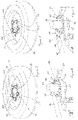
- the apparatus 10 shown individually in Figures 1 to 4 and shown in use in Figures 5 to 12 is to be used primarily for visually indicating a loose wheel nut on a wheel of a road motor vehicle, but may also be used to prevent any loosening of an adjacent wheel nut which, in turn, may restrain any further loosening of the loose wheel nut.
- the apparatus 10 has a plurality of wheel nut engaging members 12, 14, 16, 18, 20 for engaging around respective wheel nuts (as shown by numeral 22 in Figures 5 and 6 and by numerals 57, 58, 59, 60 and 61 in Figures 7 to 12 ) which are adjacent to each other and arranged as a part of a conventional, equally spaced, circular arrangement of wheel nuts engaged to wheel studs around the hub flange of a disc wheel.
- the apparatus 10 therefore defines an endless configuration of spaced apart wheel nut engaging members 12, 14, 16, 18 and 20.
- the engaging members are rings, but they may alternatively be caps, loops, covers or other suitable means for engaging all of the wheel nuts on a wheel.
- each ring 12, 14, 16, 18, 20 are rotatable with their respective wheel nut by having, in this embodiment, spaced apart transverse grooves 24 formed on their inwardly facing surface so as to grip the wheel nut around its angled corners.
- Such common rotation may alternatively be due to some other form of profile or shape on one or more inwardly facing surface of the wheel nut engaging member which creates the necessary grip, or due to the tightness with which the wheel nut engaging member grips the nut.
- each ring has a tapered lower inner edge for receiving and accommodating wheel nuts of varying sizes.
- the rings 12, 14, 16, 18, 20 have a respective pointer 26 which indicates a start position of each ring.
- Each pointer 26 is, in this embodiment, in the shape of an arrowhead and is formed integrally with its ring.
- the pointer may be in the form of a barb or be otherwise wedge shaped, or may comprise some other form of a visual indicator of a start position, such as a printed, grooved or embossed line.
- any two adjacent rings of the apparatus 10 are interconnected by an elongate member 28 which is made of a resiliently flexible material, such as polypropylene or a low density polyethylene (LDPE) or other suitable polymer material, so as to define an endless configuration of spaced apart rings which are interconnected by individual elongate members 28.
- a resiliently flexible material such as polypropylene or a low density polyethylene (LDPE) or other suitable polymer material
- the apparatus 10 has a pair of cut-outs 42, 44 formed on opposite sides of each pointer 26, and has a plurality of raised lines 46 or ribs formed on the upper surface of an upwardly projecting annulus portion 48 immediately surrounding the grooves 24 of each ring 12, 14, 16, 18, 20.
- there are twelve raised lines 46 which are equidistant and radially spaced apart from each other, but the number of such lines may vary or they may be absent.
- the elongate members 28 are formed integrally with the rings 12, 14, 16, 18, 20 which are thus made of the same polymer material as the elongate members, such as by a plastic injection moulding process.
- Each elongate member 28 is configured to curve in at least two directions.
- this curved configuration of the elongate member 28 is in the general shape of a zig zag, although the curved configuration may alternatively be in a general serpentine shape or in the shape of some other wave form or the letter Z.
- each elongate member must be configured in such a way as to be clear of, and not interfere with, any central drive axle assembly of a wheel to which the apparatus 10 is engaged, so long as each elongate member remains resiliently flexible.
- the elongate member 28 curves in two directions with a central linear region 30 therebetween.
- first and second joining portions 32, 34 of the elongate member 28 at respective opposite ends thereof.
- the joining portions 32, 34 are connected to the respective rings of any two adjacent rings of the plurality.
- the resiliently flexible elongate members 28 allow the apparatus of the present invention to radially expand and contract in order to engage wheels having different spacing of wheel nuts (and of the studs 49 to which the nuts are fitted) from a centre point of the wheels.
- each of the first and second joining portions 32, 34 is connected to its respective ring in a direction that is generally tangential thereto, although other suitable directions at which the joining portions 32, 34 are connected to the rings are within the ambit of the invention, such as perpendicular directions.
- the joining portion 32 at the left end of the elongate member 28 (when observing it from inside the apparatus 10, such as from a centre point of a wheel to which the apparatus 10 is engaged) is connected to the ring 12 at a location of the ring which, if the direction of the pointer 26 corresponds to the twelve position for an hour hand of a clock (or 0° of arc), corresponds to between the three and four position for the hour hand of the clock (or 90° to 120° of arc), and the joining portion 34 at the right end of the elongate member 28 is connected to the ring 14 at a location of the ring which corresponds to between the seven and eight position for the hour hand of the clock (or 210° to 240° of arc).
- connection configuration is most useful, where the wheel nut tightening direction is clockwise, for enhancing the visual indication of a loose wheel nut (which loosens in an anticlockwise direction) and for enhancing the prevention of any loosening of an adjacent wheel nut which, in turn, may enhance the restraining of further loosening of the loose wheel nut.
- an apparatus 10 is engaged to all of the wheel nuts on a disc wheel of a road motor vehicle. This is especially shown in Figures 7, 8 and 11 .
- each of the rings 12, 14, 16, 18, 20 indicated by the respective pointer 26 is such that the pointer 26 is directed, or points radially, outwardly from a centre point of the wheel and from which the wheel nuts are equally spaced.
- the start position may be such that the pointers are directed, or point radially, inwardly toward the centre point, or may be such that the pointers are aligned with the direction of rotation of the wheel.
- the start position may, if there are an even number of wheel nuts on a wheel that need to be engaged by the apparatus of the present invention, be such that the pair of pointers of each adjacent pair of wheel nut engaging members point toward each other.
- any loosening rotation of a first wheel nut will cause the ring which engages that wheel nut, say, ring 12 and its pointer 26, to rotate therewith, thereby providing a visual indication of a loosening of the first wheel nut.
- This will also cause the elongate member 28 connected to the right side of the ring (when observing it from inside the apparatus 10) to become straighter and the elongate member 28 connected to the left side of the ring to become straighter, and so provide a further visual indication of the loose first wheel nut. This is shown in Figures 9 and 10 and is especially apparent in Figure 12 with regard to wheel nut 57.
- connection configuration of the elongate members 28 is such that any straightening of the elongate members 28 on both sides of the ring 12 caused by loosening of the first wheel nut 57 which is engaged by ring 12 will cause the elongate members 28 to apply a compressive tension on each of the rings 14, 20 which are on opposite sides of the ring 12, thereby countering or preventing any loosening rotation of the wheel nuts 58, 61 which are engaged by rings 14, 20, respectfully, so as to prevent any loosening thereof.
- connection configuration of the elongate members 28 is such that the compressive tension applied on each of the rings 14, 20 will cause the elongate members 28 to apply a compressive tension on the ring 12, thereby countering or preventing any further loosening rotation of the first wheel nut 57 so as to restrain any further loosening thereof.
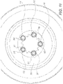
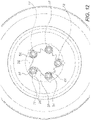
- Figures 11 and 12 show the use of the apparatus 10 shown in Figures 1 to 4 engaged to all of the wheel nuts 57, 58, 59, 60, 61 on a disc wheel 70 of a road motor vehicle.
- Figure 11 shows the start position of the pointer 26 of each ring 12, 14, 16, 18, 20 of the apparatus 10.
- the pointer 26 of each ring of the apparatus 10 points in a direction that is radially outward from a centre point of the wheel.
- Figure 12 shows that, with use of the wheel, there has been a loosening (counter clockwise) rotation of the wheel nut 57 to which ring 12 is engaged. This has caused the ring 12 and its respective pointer 26 to rotate therewith, thereby providing a visual indication of a loosening of the nut 57. This has also caused the elongate members 28 on both sides of the ring 12 to straighten, and so provide a further visual indication of the loose wheel nut 57.
- the straightening of the elongate members 28 has also applied a compressive tension on the rings 14 and 20 (such that the rings 14 and 20 would apply a tightening clockwise rotation force on the nuts 58 and 61, respectively), thereby countering or preventing any loosening (counter clockwise) rotation of the wheel nuts 58 and 61 so as to prevent any loosening thereof.
- the compressive tension applied on the rings 14 and 20 has also caused the elongate members 28 to apply a compressive tension on the ring 12, thereby countering or preventing any further loosening rotation of the wheel nut 57 so as to restrain any further loosening thereof.
- the apparatus 72 shown in use in Figure 13 , the apparatus 74 shown in use in Figure 14 , and the apparatus 76 shown in use in Figure 15 are each engaged to all of the ten wheel nuts 77 of a respective disc wheel 70 of a road motor vehicle, and are used for generally the same purpose as the apparatus 10.
- the structure and function of each of the apparatus 72, 74 and 76 shown in Figures 13 , 14 and 15 , respectively, are the same as the structure and function of the apparatus 10 described hereinbefore with reference to Figures 1 to 12 , and like features may be identified by like numerals.
- the wheel nut engaging members of apparatus 72 are extended rings 80, each of which engages a respective wheel nut 77 which is recessed on a wheel 70 in such a way that the extended ring 80 may extend below the wheel disc to the hub flange of the wheel 70 and so fully cover the sides of the nut 77.
- Such nuts may be said to be recess mounted on the wheel, and are commonly called recessed nuts.
- the extended ring 80 is open at its top, or uncapped, whereby the top of the nut 77 is visible.
- the pointer 84 of each extended, uncapped ring 80 extends from the top of the ring 80, and the elongate member 86 which interconnects any two adjacent rings 80 also extends from the top of the rings 80.
- the wheel nut engaging members of apparatus 74 are also extended rings 90, similar to the extended rings 80, but in this embodiment, each of the extended rings 90 is closed at its top, or capped, whereby the top of the nut is not visible.
- the closed top 92, or cap, of the ring 90 is, in this embodiment, slightly dome shaped and is formed integrally with its ring 90.
- the wheel nut engaging members of apparatus 76 are also extended rings 100, similar to the extended rings 90, whereby each of the extended rings 100 has a closed top 102, or cap, but in this embodiment, each of the pointers 104 of each extended, capped ring 100 extends from the bottom of the ring 100, and the elongate member 106 which interconnects any two adjacent rings 100 also extends from the bottom of the rings 100.
- Such an extended ring 100 because the pointer 104 and the elongate member 106 are located at the bottom of the ring 100, may not be used with a recessed nut, but may nonetheless provide the nut and its stud with protection from dust, by serving as a dust cap or cover.
Landscapes
- Engineering & Computer Science (AREA)
- Mechanical Engineering (AREA)
- General Engineering & Computer Science (AREA)
- Force Measurement Appropriate To Specific Purposes (AREA)
- Connection Of Plates (AREA)
- Road Signs Or Road Markings (AREA)
- Braking Arrangements (AREA)
- Automobile Manufacture Line, Endless Track Vehicle, Trailer (AREA)
- Rolling Contact Bearings (AREA)
Claims (10)
- Vorrichtung zur visuellen Anzeige einer lockeren Radmutter an einem Rad eines Kraftfahrzeugs, die eine Vielzahl von Radmuttereingriffselementen (12, 14, 16, 18, 20) umfasst, wobei jedes Eingriffselement (12, 14, 16, 18, 20) mit einer entsprechenden Radmutter (22, 57 - 59, 61, 80), mit der es in Eingriff steht, drehbar ist und einen Zeiger (26) zur Anzeige einer Startposition des Eingriffselements (12, 14, 16, 18, 20) aufweist, wobei jeweils zwei benachbarte Eingriffselemente (12, 14, 16, 18, 20) der Vielzahl durch ein längliches Element (28) miteinander verbunden sind, das elastisch flexibel ist, um eine endlose Konfiguration von voneinander beabstandeten, aber miteinander verbundenen Eingriffselementen (12, 14, 16, 18, 20) zu definieren, wobei im Gebrauch jede Lockerungsdrehung einer ersten Radmutter das Eingriffselement (12, 14, 16, 18, 20), das mit dieser Radmutter und ihrem Zeiger (26) in Eingriff steht, veranlasst, sich mit ihr zu drehen, wodurch eine visuelle Anzeige einer Lockerung dieser Radmutter (22, 57 - 59, 61, 80) bereitgestellt wird, dadurch gekennzeichnet, dass die Vielzahl von Radmutterneingriffselementen (12, 14, 16, 18, 20), die die endlose Konfiguration definieren, einstückig mit den Zeigern (26) und den verbindenden länglichen Elementen (28) gebildet sind.
- Vorrichtung nach Anspruch 1, wobei das längliche Element (28) so konfiguriert ist, dass jede durch das Lösen der ersten Radmutter verursachte Begradigung des länglichen Elements (28) bewirkt, dass das längliche Element (28) eine Druckspannung auf ein zweites Eingriffselement ausübt, mit dem das längliche Element (28) verbunden ist, wodurch einer Lockerungsdrehung einer zweiten Radmutter, mit der das zweite Eingriffselement verbunden ist, entgegengewirkt wird, um eine Lockerung zu verhindern.
- Vorrichtung nach Anspruch 2, wobei das längliche Element (28) so konfiguriert ist, dass die auf das zweite Eingriffselement ausgeübte Druckspannung das längliche Element (28) veranlasst, eine Druckspannung auf das erste Eingriffselement auszuüben, wodurch jeder weiteren Lockerungsdrehung der ersten Radmutter entgegenwirkt wird, um jede weitere Lockerung derselben zu verhindern.
- Vorrichtung nach Anspruch 1, wobei jedes der Radmuttereingriffselemente (12, 14, 16, 18, 20) aus der Gruppe ausgewählt ist, die aus Ringen, Kappen, Schlaufen und Abdeckungen besteht.
- Vorrichtung nach Anspruch 1, wobei jedes der Radmutterneingriffselemente (12, 14, 16, 18, 20) ein Ring ist, der voneinander beabstandete Quernuten (24) aufweist, die auf der nach innen weisenden Oberfläche des Rings gebildet sind, um die Radmutter um ihre abgewinkelten Ecken zu greifen.
- Vorrichtung nach Anspruch 1, wobei jedes der Radmutterneingriffselemente (12, 14, 16, 18, 20) eine Kappe ist, der voneinander beabstandete Quernuten (24) aufweist, die auf der nach innen weisenden Oberfläche der Kappe gebildet sind, um die Radmutter um ihre abgewinkelten Ecken zu greifen.
- Vorrichtung nach Anspruch 1, wobei das längliche Element (28) so konfiguriert ist, dass es die allgemeine Form eines Zickzacks aufweist.
- Vorrichtung nach Anspruch 1, wobei jeder der Zeiger (26) eine Pfeilspitze aufweist, die einstückig mit dem jeweiligen Eingriffselement (12, 14, 16, 18, 20) gebildet ist.
- Vorrichtung nach Anspruch 1, wobei die Vielzahl von Radmuttereingriffselementen (12, 14, 16, 18, 20) aus einer ungeraden Anzahl von Radmuttereingriffselementen (12, 14, 16, 18, 20) besteht.
- Verfahren zur visuellen Anzeige einer lockeren Radmutter an einem Kraftfahrzeug, das folgende Schritte umfasst:(a) Bereitstellen einer Vorrichtung nach Anspruch 1,(b) In-Eingriff-Bringen der Radmuttereingriffselemente (12, 14, 16, 18, 20) mit entsprechenden Radmuttern (22, 57 - 59, 61, 80), wobei die Startposition jedes der Radmutterneingriffselemente (12, 14, 16, 18, 20) durch seinen jeweiligen Zeiger (26) angezeigt wird, und(c) visuelles Überwachen jeder Drehung des Zeigers (26) eines der Radmuttereingriffselemente (12, 14, 16, 18, 20), um ein Lösen der jeweiligen Radmutter (22, 57 - 59, 61, 80) anzuzeigen.
Applications Claiming Priority (2)
| Application Number | Priority Date | Filing Date | Title |
|---|---|---|---|
| AU2015901412A AU2015901412A0 (en) | 2015-04-20 | Improved loose wheel nut indicator | |
| PCT/AU2016/000134 WO2016168883A1 (en) | 2015-04-20 | 2016-04-20 | Improved loose wheel nut indicator and restrainer |
Publications (3)
| Publication Number | Publication Date |
|---|---|
| EP3286016A1 EP3286016A1 (de) | 2018-02-28 |
| EP3286016A4 EP3286016A4 (de) | 2018-12-26 |
| EP3286016B1 true EP3286016B1 (de) | 2022-06-01 |
Family
ID=57142745
Family Applications (1)
| Application Number | Title | Priority Date | Filing Date |
|---|---|---|---|
| EP16782387.1A Active EP3286016B1 (de) | 2015-04-20 | 2016-04-20 | Verbesserter indikator und rückhalter für lockere radmutter |
Country Status (7)
| Country | Link |
|---|---|
| US (1) | US10428861B2 (de) |
| EP (1) | EP3286016B1 (de) |
| CN (1) | CN107531087B (de) |
| AU (1) | AU2016250898B2 (de) |
| CA (1) | CA2970814C (de) |
| ES (1) | ES2925884T3 (de) |
| WO (1) | WO2016168883A1 (de) |
Families Citing this family (8)
| Publication number | Priority date | Publication date | Assignee | Title |
|---|---|---|---|---|
| CN109372877A (zh) * | 2018-11-22 | 2019-02-22 | 福建省晋江市励精汽配有限公司 | 紧固件防松装置、盘式防松装置、紧固装置和车轮 |
| US12194779B2 (en) * | 2019-04-16 | 2025-01-14 | Moochout Llc | Systems and methods for identifying and mitigating lug nut loosening |
| US20210362541A1 (en) * | 2020-05-19 | 2021-11-25 | Ifor C. Davies | Thermochromic wheel lug nut device |
| US12104641B2 (en) * | 2020-06-23 | 2024-10-01 | InSitu, Inc., a subsidiary of the Boeing Company | Retention washers, propeller retention systems, and related methods |
| US12024310B2 (en) | 2021-04-08 | 2024-07-02 | The Boeing Company | Ignition-suppressing devices for shielding fasteners, aircraft fuel tanks having fasteners shielded by ignition-suppressing devices, and methods of installing ignition-suppressing devices in aircraft fuel tanks |
| JP7764822B2 (ja) * | 2022-09-12 | 2025-11-06 | トヨタ自動車株式会社 | 車輪状態取得システムおよび車輪状態取得方法 |
| CN115493478A (zh) * | 2022-09-28 | 2022-12-20 | 上海汽车集团股份有限公司 | 一种车轮螺母松动检测装置以及车辆 |
| DE102023124424A1 (de) * | 2023-09-11 | 2025-03-13 | Weidmüller Interface GmbH & Co. KG | Überwachungsaufsatz für eine Mutter und Anordnung mit mindestens zwei derartigen Überwachungsaufsätzen |
Family Cites Families (18)
| Publication number | Priority date | Publication date | Assignee | Title |
|---|---|---|---|---|
| US1741077A (en) * | 1927-03-18 | 1929-12-24 | Rusack Herman | Nut lock |
| US5624218A (en) * | 1995-09-12 | 1997-04-29 | Dauwalter; Charles G. | Safety lock device for screw fasteners |
| US6398312B1 (en) * | 1998-04-24 | 2002-06-04 | Business Lines Limited | Combined dust cap and position indicating device, particularly for vehicle wheel nuts |
| CA2354799A1 (en) * | 2000-08-03 | 2002-02-03 | Louis J. Illes | Wheel nut indicator assembly for vehicle wheels |
| GB2393487B (en) * | 2002-08-29 | 2007-02-07 | Universal Product Dev Ltd | Wheel nut indicator and retention device |
| US20040181924A1 (en) * | 2003-03-19 | 2004-09-23 | Saunders John H. | Removable lug nut locking apparatus, cover, removal tool and methods of use |
| GB2406365B (en) * | 2003-09-26 | 2006-07-12 | Business Lines Ltd | Security device for adjacent nuts or bolts |
| GB2408783A (en) * | 2003-12-03 | 2005-06-08 | Charles Robert Massie | Vehicle wheel locking assembly |
| GB2409251B (en) * | 2003-12-17 | 2006-06-21 | Business Lines Ltd | A safety device particularly for multiple wheel nuts |
| GB2454164B (en) * | 2007-08-25 | 2011-10-12 | Business Lines Ltd | Rotation indicator device |
| US7927049B2 (en) * | 2007-08-27 | 2011-04-19 | Adams James C | Wheel lug nut management device |
| GB0723769D0 (en) * | 2007-12-05 | 2008-01-16 | Interparts Automotive B V | Fasteners lock |
| CA2637356C (en) * | 2008-07-10 | 2014-04-15 | Ifor C. Davies | Wheel lug nut locking device |
| US8337129B2 (en) * | 2010-04-09 | 2012-12-25 | Bruce Richard Boyce | Wheel nut lock |
| GB2510170B (en) * | 2013-01-28 | 2015-10-14 | Business Lines Ltd | Security device for connecting together adjacent wheel nut covers |
| CA2913057C (en) * | 2013-07-05 | 2021-07-06 | Marchmont Pty Limited | Loose wheel nut indicator |
| US9057396B2 (en) * | 2013-09-19 | 2015-06-16 | Lenny Prince | Lug nut locking device |
| CA2954609A1 (en) * | 2016-01-15 | 2017-07-15 | Justin C. Ellis | Wheel hub safety devices, systems and methods |
-
2016
- 2016-04-20 US US15/514,538 patent/US10428861B2/en active Active
- 2016-04-20 AU AU2016250898A patent/AU2016250898B2/en not_active Ceased
- 2016-04-20 CA CA2970814A patent/CA2970814C/en active Active
- 2016-04-20 EP EP16782387.1A patent/EP3286016B1/de active Active
- 2016-04-20 ES ES16782387T patent/ES2925884T3/es active Active
- 2016-04-20 CN CN201680018260.9A patent/CN107531087B/zh not_active Expired - Fee Related
- 2016-04-20 WO PCT/AU2016/000134 patent/WO2016168883A1/en not_active Ceased
Also Published As
| Publication number | Publication date |
|---|---|
| US20170227042A1 (en) | 2017-08-10 |
| CA2970814A1 (en) | 2016-10-27 |
| CA2970814C (en) | 2021-12-07 |
| US10428861B2 (en) | 2019-10-01 |
| EP3286016A4 (de) | 2018-12-26 |
| EP3286016A1 (de) | 2018-02-28 |
| CN107531087A (zh) | 2018-01-02 |
| ES2925884T3 (es) | 2022-10-20 |
| AU2016250898A1 (en) | 2017-07-06 |
| CN107531087B (zh) | 2020-09-01 |
| AU2016250898B2 (en) | 2020-05-28 |
| WO2016168883A1 (en) | 2016-10-27 |
Similar Documents
| Publication | Publication Date | Title |
|---|---|---|
| EP3286016B1 (de) | Verbesserter indikator und rückhalter für lockere radmutter | |
| EP3017203B1 (de) | Indikator für lockere radmutter | |
| EP2419651B1 (de) | Sicherungsvorrichtung für befestigungselemente mit gewinde | |
| US9057396B2 (en) | Lug nut locking device | |
| EP0024935A1 (de) | Radmutter | |
| WO2005059381A1 (en) | A safety device particularly for multiple wheel nuts | |
| US20120141226A1 (en) | Locking system and method of using same | |
| EP3652452B1 (de) | Steckbolzen | |
| US20110305539A1 (en) | Protective Cover Adapted For A Visual Aid | |
| US20190055970A1 (en) | Indicators and assemblies thereof | |
| CN106224357A (zh) | 一种车轮 | |
| EP2816244B1 (de) | Anti-Diebstahl-Verriegelungsvorrichtung für Fahrzeugräder | |
| WO2016128714A1 (en) | A device and method for retaining a nut | |
| CA1226156A (en) | Nut lock assembly | |
| US10533600B1 (en) | Threaded fastener locking system | |
| CA2734659A1 (en) | Lug nut locking device | |
| IE901885A1 (en) | Self threading and locking fasteners | |
| GB2518409A (en) | Wheel nut locking device | |
| WO2000079140A1 (en) | Wheel nut locking assembly | |
| WO2016166551A1 (en) | Locking device for a nut such as a wheel nut | |
| AU2010101053A4 (en) | A fastener including rotation indication means | |
| US20170241468A1 (en) | Lug Nut Covers |
Legal Events
| Date | Code | Title | Description |
|---|---|---|---|
| STAA | Information on the status of an ep patent application or granted ep patent |
Free format text: STATUS: THE INTERNATIONAL PUBLICATION HAS BEEN MADE |
|
| PUAI | Public reference made under article 153(3) epc to a published international application that has entered the european phase |
Free format text: ORIGINAL CODE: 0009012 |
|
| STAA | Information on the status of an ep patent application or granted ep patent |
Free format text: STATUS: REQUEST FOR EXAMINATION WAS MADE |
|
| 17P | Request for examination filed |
Effective date: 20171019 |
|
| AK | Designated contracting states |
Kind code of ref document: A1 Designated state(s): AL AT BE BG CH CY CZ DE DK EE ES FI FR GB GR HR HU IE IS IT LI LT LU LV MC MK MT NL NO PL PT RO RS SE SI SK SM TR |
|
| AX | Request for extension of the european patent |
Extension state: BA ME |
|
| DAV | Request for validation of the european patent (deleted) | ||
| DAX | Request for extension of the european patent (deleted) | ||
| A4 | Supplementary search report drawn up and despatched |
Effective date: 20181123 |
|
| RIC1 | Information provided on ipc code assigned before grant |
Ipc: B60B 3/16 20060101AFI20181119BHEP Ipc: F16B 39/10 20060101ALI20181119BHEP Ipc: F16B 1/00 20060101ALI20181119BHEP |
|
| GRAP | Despatch of communication of intention to grant a patent |
Free format text: ORIGINAL CODE: EPIDOSNIGR1 |
|
| STAA | Information on the status of an ep patent application or granted ep patent |
Free format text: STATUS: GRANT OF PATENT IS INTENDED |
|
| INTG | Intention to grant announced |
Effective date: 20211117 |
|
| GRAS | Grant fee paid |
Free format text: ORIGINAL CODE: EPIDOSNIGR3 |
|
| GRAA | (expected) grant |
Free format text: ORIGINAL CODE: 0009210 |
|
| STAA | Information on the status of an ep patent application or granted ep patent |
Free format text: STATUS: THE PATENT HAS BEEN GRANTED |
|
| AK | Designated contracting states |
Kind code of ref document: B1 Designated state(s): AL AT BE BG CH CY CZ DE DK EE ES FI FR GB GR HR HU IE IS IT LI LT LU LV MC MK MT NL NO PL PT RO RS SE SI SK SM TR |
|
| REG | Reference to a national code |
Ref country code: GB Ref legal event code: FG4D |
|
| REG | Reference to a national code |
Ref country code: AT Ref legal event code: REF Ref document number: 1495136 Country of ref document: AT Kind code of ref document: T Effective date: 20220615 Ref country code: CH Ref legal event code: EP |
|
| REG | Reference to a national code |
Ref country code: IE Ref legal event code: FG4D |
|
| REG | Reference to a national code |
Ref country code: DE Ref legal event code: R096 Ref document number: 602016072544 Country of ref document: DE |
|
| REG | Reference to a national code |
Ref country code: NL Ref legal event code: FP |
|
| REG | Reference to a national code |
Ref country code: SE Ref legal event code: TRGR |
|
| REG | Reference to a national code |
Ref country code: LT Ref legal event code: MG9D |
|
| REG | Reference to a national code |
Ref country code: ES Ref legal event code: FG2A Ref document number: 2925884 Country of ref document: ES Kind code of ref document: T3 Effective date: 20221020 |
|
| PG25 | Lapsed in a contracting state [announced via postgrant information from national office to epo] |
Ref country code: NO Free format text: LAPSE BECAUSE OF FAILURE TO SUBMIT A TRANSLATION OF THE DESCRIPTION OR TO PAY THE FEE WITHIN THE PRESCRIBED TIME-LIMIT Effective date: 20220901 Ref country code: LT Free format text: LAPSE BECAUSE OF FAILURE TO SUBMIT A TRANSLATION OF THE DESCRIPTION OR TO PAY THE FEE WITHIN THE PRESCRIBED TIME-LIMIT Effective date: 20220601 Ref country code: HR Free format text: LAPSE BECAUSE OF FAILURE TO SUBMIT A TRANSLATION OF THE DESCRIPTION OR TO PAY THE FEE WITHIN THE PRESCRIBED TIME-LIMIT Effective date: 20220601 Ref country code: GR Free format text: LAPSE BECAUSE OF FAILURE TO SUBMIT A TRANSLATION OF THE DESCRIPTION OR TO PAY THE FEE WITHIN THE PRESCRIBED TIME-LIMIT Effective date: 20220902 Ref country code: FI Free format text: LAPSE BECAUSE OF FAILURE TO SUBMIT A TRANSLATION OF THE DESCRIPTION OR TO PAY THE FEE WITHIN THE PRESCRIBED TIME-LIMIT Effective date: 20220601 Ref country code: BG Free format text: LAPSE BECAUSE OF FAILURE TO SUBMIT A TRANSLATION OF THE DESCRIPTION OR TO PAY THE FEE WITHIN THE PRESCRIBED TIME-LIMIT Effective date: 20220901 |
|
| REG | Reference to a national code |
Ref country code: AT Ref legal event code: MK05 Ref document number: 1495136 Country of ref document: AT Kind code of ref document: T Effective date: 20220601 |
|
| PG25 | Lapsed in a contracting state [announced via postgrant information from national office to epo] |
Ref country code: RS Free format text: LAPSE BECAUSE OF FAILURE TO SUBMIT A TRANSLATION OF THE DESCRIPTION OR TO PAY THE FEE WITHIN THE PRESCRIBED TIME-LIMIT Effective date: 20220601 Ref country code: PL Free format text: LAPSE BECAUSE OF FAILURE TO SUBMIT A TRANSLATION OF THE DESCRIPTION OR TO PAY THE FEE WITHIN THE PRESCRIBED TIME-LIMIT Effective date: 20220601 Ref country code: LV Free format text: LAPSE BECAUSE OF FAILURE TO SUBMIT A TRANSLATION OF THE DESCRIPTION OR TO PAY THE FEE WITHIN THE PRESCRIBED TIME-LIMIT Effective date: 20220601 |
|
| PG25 | Lapsed in a contracting state [announced via postgrant information from national office to epo] |
Ref country code: SM Free format text: LAPSE BECAUSE OF FAILURE TO SUBMIT A TRANSLATION OF THE DESCRIPTION OR TO PAY THE FEE WITHIN THE PRESCRIBED TIME-LIMIT Effective date: 20220601 Ref country code: SK Free format text: LAPSE BECAUSE OF FAILURE TO SUBMIT A TRANSLATION OF THE DESCRIPTION OR TO PAY THE FEE WITHIN THE PRESCRIBED TIME-LIMIT Effective date: 20220601 Ref country code: RO Free format text: LAPSE BECAUSE OF FAILURE TO SUBMIT A TRANSLATION OF THE DESCRIPTION OR TO PAY THE FEE WITHIN THE PRESCRIBED TIME-LIMIT Effective date: 20220601 Ref country code: PT Free format text: LAPSE BECAUSE OF FAILURE TO SUBMIT A TRANSLATION OF THE DESCRIPTION OR TO PAY THE FEE WITHIN THE PRESCRIBED TIME-LIMIT Effective date: 20221003 Ref country code: EE Free format text: LAPSE BECAUSE OF FAILURE TO SUBMIT A TRANSLATION OF THE DESCRIPTION OR TO PAY THE FEE WITHIN THE PRESCRIBED TIME-LIMIT Effective date: 20220601 Ref country code: CZ Free format text: LAPSE BECAUSE OF FAILURE TO SUBMIT A TRANSLATION OF THE DESCRIPTION OR TO PAY THE FEE WITHIN THE PRESCRIBED TIME-LIMIT Effective date: 20220601 Ref country code: AT Free format text: LAPSE BECAUSE OF FAILURE TO SUBMIT A TRANSLATION OF THE DESCRIPTION OR TO PAY THE FEE WITHIN THE PRESCRIBED TIME-LIMIT Effective date: 20220601 |
|
| PG25 | Lapsed in a contracting state [announced via postgrant information from national office to epo] |
Ref country code: IS Free format text: LAPSE BECAUSE OF FAILURE TO SUBMIT A TRANSLATION OF THE DESCRIPTION OR TO PAY THE FEE WITHIN THE PRESCRIBED TIME-LIMIT Effective date: 20221001 |
|
| REG | Reference to a national code |
Ref country code: DE Ref legal event code: R097 Ref document number: 602016072544 Country of ref document: DE |
|
| PG25 | Lapsed in a contracting state [announced via postgrant information from national office to epo] |
Ref country code: AL Free format text: LAPSE BECAUSE OF FAILURE TO SUBMIT A TRANSLATION OF THE DESCRIPTION OR TO PAY THE FEE WITHIN THE PRESCRIBED TIME-LIMIT Effective date: 20220601 |
|
| PLBE | No opposition filed within time limit |
Free format text: ORIGINAL CODE: 0009261 |
|
| STAA | Information on the status of an ep patent application or granted ep patent |
Free format text: STATUS: NO OPPOSITION FILED WITHIN TIME LIMIT |
|
| PG25 | Lapsed in a contracting state [announced via postgrant information from national office to epo] |
Ref country code: DK Free format text: LAPSE BECAUSE OF FAILURE TO SUBMIT A TRANSLATION OF THE DESCRIPTION OR TO PAY THE FEE WITHIN THE PRESCRIBED TIME-LIMIT Effective date: 20220601 |
|
| 26N | No opposition filed |
Effective date: 20230302 |
|
| PG25 | Lapsed in a contracting state [announced via postgrant information from national office to epo] |
Ref country code: SI Free format text: LAPSE BECAUSE OF FAILURE TO SUBMIT A TRANSLATION OF THE DESCRIPTION OR TO PAY THE FEE WITHIN THE PRESCRIBED TIME-LIMIT Effective date: 20220601 |
|
| REG | Reference to a national code |
Ref country code: DE Ref legal event code: R119 Ref document number: 602016072544 Country of ref document: DE |
|
| REG | Reference to a national code |
Ref country code: SE Ref legal event code: EUG |
|
| REG | Reference to a national code |
Ref country code: CH Ref legal event code: PL |
|
| REG | Reference to a national code |
Ref country code: NL Ref legal event code: MM Effective date: 20230501 |
|
| GBPC | Gb: european patent ceased through non-payment of renewal fee |
Effective date: 20230420 |
|
| PG25 | Lapsed in a contracting state [announced via postgrant information from national office to epo] |
Ref country code: LU Free format text: LAPSE BECAUSE OF NON-PAYMENT OF DUE FEES Effective date: 20230420 |
|
| REG | Reference to a national code |
Ref country code: BE Ref legal event code: MM Effective date: 20230430 |
|
| PG25 | Lapsed in a contracting state [announced via postgrant information from national office to epo] |
Ref country code: MC Free format text: LAPSE BECAUSE OF FAILURE TO SUBMIT A TRANSLATION OF THE DESCRIPTION OR TO PAY THE FEE WITHIN THE PRESCRIBED TIME-LIMIT Effective date: 20220601 |
|
| PG25 | Lapsed in a contracting state [announced via postgrant information from national office to epo] |
Ref country code: GB Free format text: LAPSE BECAUSE OF NON-PAYMENT OF DUE FEES Effective date: 20230420 |
|
| PG25 | Lapsed in a contracting state [announced via postgrant information from national office to epo] |
Ref country code: SE Free format text: LAPSE BECAUSE OF NON-PAYMENT OF DUE FEES Effective date: 20230421 Ref country code: NL Free format text: LAPSE BECAUSE OF NON-PAYMENT OF DUE FEES Effective date: 20230501 Ref country code: MC Free format text: LAPSE BECAUSE OF FAILURE TO SUBMIT A TRANSLATION OF THE DESCRIPTION OR TO PAY THE FEE WITHIN THE PRESCRIBED TIME-LIMIT Effective date: 20220601 Ref country code: LI Free format text: LAPSE BECAUSE OF NON-PAYMENT OF DUE FEES Effective date: 20230430 Ref country code: GB Free format text: LAPSE BECAUSE OF NON-PAYMENT OF DUE FEES Effective date: 20230420 Ref country code: FR Free format text: LAPSE BECAUSE OF NON-PAYMENT OF DUE FEES Effective date: 20230430 Ref country code: DE Free format text: LAPSE BECAUSE OF NON-PAYMENT OF DUE FEES Effective date: 20231103 Ref country code: CH Free format text: LAPSE BECAUSE OF NON-PAYMENT OF DUE FEES Effective date: 20230430 |
|
| REG | Reference to a national code |
Ref country code: NL Ref legal event code: NE Effective date: 20240126 |
|
| REG | Reference to a national code |
Ref country code: BE Ref legal event code: NE Effective date: 20240129 |
|
| PG25 | Lapsed in a contracting state [announced via postgrant information from national office to epo] |
Ref country code: BE Free format text: LAPSE BECAUSE OF NON-PAYMENT OF DUE FEES Effective date: 20230430 |
|
| REG | Reference to a national code |
Ref country code: DE Ref legal event code: R082 Ref document number: 602016072544 Country of ref document: DE Representative=s name: PATENTANWAELTE BAUER VORBERG KAYSER PARTNERSCH, DE |
|
| PG25 | Lapsed in a contracting state [announced via postgrant information from national office to epo] |
Ref country code: IT Free format text: LAPSE BECAUSE OF NON-PAYMENT OF DUE FEES Effective date: 20230420 |
|
| REG | Reference to a national code |
Ref country code: DE Ref legal event code: R073 Ref document number: 602016072544 Country of ref document: DE |
|
| REG | Reference to a national code |
Ref country code: NL Ref legal event code: NF Effective date: 20240621 |
|
| PGFP | Annual fee paid to national office [announced via postgrant information from national office to epo] |
Ref country code: IE Payment date: 20240422 Year of fee payment: 9 |
|
| PG25 | Lapsed in a contracting state [announced via postgrant information from national office to epo] |
Ref country code: NL Free format text: LAPSE BECAUSE OF NON-PAYMENT OF DUE FEES Effective date: 20230501 |
|
| PGFP | Annual fee paid to national office [announced via postgrant information from national office to epo] |
Ref country code: NL Payment date: 20240621 Year of fee payment: 9 |
|
| PGRI | Patent reinstated in contracting state [announced from national office to epo] |
Ref country code: NL Effective date: 20240621 |
|
| PGFP | Annual fee paid to national office [announced via postgrant information from national office to epo] |
Ref country code: ES Payment date: 20240603 Year of fee payment: 9 |
|
| REG | Reference to a national code |
Ref country code: DE Ref legal event code: R074 Ref document number: 602016072544 Country of ref document: DE |
|
| PG25 | Lapsed in a contracting state [announced via postgrant information from national office to epo] |
Ref country code: NL Free format text: LAPSE BECAUSE OF NON-PAYMENT OF DUE FEES Effective date: 20230501 Ref country code: FR Free format text: LAPSE BECAUSE OF NON-PAYMENT OF DUE FEES Effective date: 20230430 |
|
| PGFP | Annual fee paid to national office [announced via postgrant information from national office to epo] |
Ref country code: FR Payment date: 20240126 Year of fee payment: 8 |
|
| PGRI | Patent reinstated in contracting state [announced from national office to epo] |
Ref country code: NL Effective date: 20240621 Ref country code: FR Effective date: 20240531 |
|
| PG25 | Lapsed in a contracting state [announced via postgrant information from national office to epo] |
Ref country code: DE Free format text: LAPSE BECAUSE OF NON-PAYMENT OF DUE FEES Effective date: 20231103 |
|
| PGFP | Annual fee paid to national office [announced via postgrant information from national office to epo] |
Ref country code: DE Payment date: 20240606 Year of fee payment: 9 |
|
| PGRI | Patent reinstated in contracting state [announced from national office to epo] |
Ref country code: DE Effective date: 20240728 |
|
| PG25 | Lapsed in a contracting state [announced via postgrant information from national office to epo] |
Ref country code: DE Free format text: LAPSE BECAUSE OF NON-PAYMENT OF DUE FEES Effective date: 20231103 |
|
| PGRI | Patent reinstated in contracting state [announced from national office to epo] |
Ref country code: DE Effective date: 20240728 |
|
| PG25 | Lapsed in a contracting state [announced via postgrant information from national office to epo] |
Ref country code: BG Free format text: LAPSE BECAUSE OF FAILURE TO SUBMIT A TRANSLATION OF THE DESCRIPTION OR TO PAY THE FEE WITHIN THE PRESCRIBED TIME-LIMIT Effective date: 20220601 |
|
| PG25 | Lapsed in a contracting state [announced via postgrant information from national office to epo] |
Ref country code: BG Free format text: LAPSE BECAUSE OF FAILURE TO SUBMIT A TRANSLATION OF THE DESCRIPTION OR TO PAY THE FEE WITHIN THE PRESCRIBED TIME-LIMIT Effective date: 20220601 |
|
| REG | Reference to a national code |
Ref country code: SE Ref legal event code: RE72 Free format text: PRV HAR I BESLUT DEN 6 DECEMBER 2024 FOERKLARAT ARSAVGIFT BETALD I TID FOER EP 3286016(16782387.1) PATENTET AER DAERMED FORTFARANDE I KRAFT. |
|
| REG | Reference to a national code |
Ref country code: GB Ref legal event code: S28 Free format text: APPLICATION FILED |
|
| PG25 | Lapsed in a contracting state [announced via postgrant information from national office to epo] |
Ref country code: FR Free format text: LAPSE BECAUSE OF NON-PAYMENT OF DUE FEES Effective date: 20240430 |
|
| PGFP | Annual fee paid to national office [announced via postgrant information from national office to epo] |
Ref country code: SE Payment date: 20241115 Year of fee payment: 9 |
|
| PG25 | Lapsed in a contracting state [announced via postgrant information from national office to epo] |
Ref country code: FR Free format text: LAPSE BECAUSE OF NON-PAYMENT OF DUE FEES Effective date: 20240430 |
|
| PGRI | Patent reinstated in contracting state [announced from national office to epo] |
Ref country code: FR Effective date: 20240531 |
|
| REG | Reference to a national code |
Ref country code: GB Ref legal event code: 732E Free format text: REGISTERED BETWEEN 20250130 AND 20250205 |
|
| REG | Reference to a national code |
Ref country code: GB Ref legal event code: S28 Free format text: RESTORATION ALLOWED Effective date: 20250516 |
|
| PGFP | Annual fee paid to national office [announced via postgrant information from national office to epo] |
Ref country code: GB Payment date: 20250415 Year of fee payment: 10 |
|
| PG25 | Lapsed in a contracting state [announced via postgrant information from national office to epo] |
Ref country code: CY Free format text: LAPSE BECAUSE OF FAILURE TO SUBMIT A TRANSLATION OF THE DESCRIPTION OR TO PAY THE FEE WITHIN THE PRESCRIBED TIME-LIMIT; INVALID AB INITIO Effective date: 20160420 |
|
| PG25 | Lapsed in a contracting state [announced via postgrant information from national office to epo] |
Ref country code: HU Free format text: LAPSE BECAUSE OF FAILURE TO SUBMIT A TRANSLATION OF THE DESCRIPTION OR TO PAY THE FEE WITHIN THE PRESCRIBED TIME-LIMIT; INVALID AB INITIO Effective date: 20160420 |
|
| REG | Reference to a national code |
Ref country code: DE Ref legal event code: R119 Ref document number: 602016072544 Country of ref document: DE |
|
| REG | Reference to a national code |
Ref country code: SE Ref legal event code: EUG |
|
| REG | Reference to a national code |
Ref country code: NL Ref legal event code: MM Effective date: 20250501 |
|
| PG25 | Lapsed in a contracting state [announced via postgrant information from national office to epo] |
Ref country code: TR Free format text: LAPSE BECAUSE OF FAILURE TO SUBMIT A TRANSLATION OF THE DESCRIPTION OR TO PAY THE FEE WITHIN THE PRESCRIBED TIME-LIMIT Effective date: 20220601 |
|
| PG25 | Lapsed in a contracting state [announced via postgrant information from national office to epo] |
Ref country code: SE Free format text: LAPSE BECAUSE OF NON-PAYMENT OF DUE FEES Effective date: 20230421 |
|
| PGRI | Patent reinstated in contracting state [announced from national office to epo] |
Ref country code: SE Effective date: 20241206 |
|
| PG25 | Lapsed in a contracting state [announced via postgrant information from national office to epo] |
Ref country code: DE Free format text: LAPSE BECAUSE OF NON-PAYMENT OF DUE FEES Effective date: 20251104 |
|
| PG25 | Lapsed in a contracting state [announced via postgrant information from national office to epo] |
Ref country code: NL Free format text: LAPSE BECAUSE OF NON-PAYMENT OF DUE FEES Effective date: 20250501 |
|
| PG25 | Lapsed in a contracting state [announced via postgrant information from national office to epo] |
Ref country code: SE Free format text: LAPSE BECAUSE OF NON-PAYMENT OF DUE FEES Effective date: 20250421 |
|
| PG25 | Lapsed in a contracting state [announced via postgrant information from national office to epo] |
Ref country code: IE Free format text: LAPSE BECAUSE OF NON-PAYMENT OF DUE FEES Effective date: 20250420 |