EP3285992B1 - Appareil et procédé pour former des objets tridimensionnels par compensation et décalage dynamique d'axe de balayage - Google Patents
Appareil et procédé pour former des objets tridimensionnels par compensation et décalage dynamique d'axe de balayage Download PDFInfo
- Publication number
- EP3285992B1 EP3285992B1 EP16783902.6A EP16783902A EP3285992B1 EP 3285992 B1 EP3285992 B1 EP 3285992B1 EP 16783902 A EP16783902 A EP 16783902A EP 3285992 B1 EP3285992 B1 EP 3285992B1
- Authority
- EP
- European Patent Office
- Prior art keywords
- scanning
- axis
- solidification
- time
- solidification energy
- Prior art date
- Legal status (The legal status is an assumption and is not a legal conclusion. Google has not performed a legal analysis and makes no representation as to the accuracy of the status listed.)
- Active
Links
- 238000000034 method Methods 0.000 title claims description 63
- 238000007711 solidification Methods 0.000 claims description 341
- 230000008023 solidification Effects 0.000 claims description 341
- 239000000463 material Substances 0.000 claims description 88
- 238000004519 manufacturing process Methods 0.000 claims description 13
- 230000003213 activating effect Effects 0.000 claims description 10
- 230000004913 activation Effects 0.000 claims description 10
- 230000009849 deactivation Effects 0.000 claims description 8
- 238000004891 communication Methods 0.000 claims description 4
- 230000003287 optical effect Effects 0.000 claims description 4
- 230000006870 function Effects 0.000 description 40
- 241000238876 Acari Species 0.000 description 35
- 239000000758 substrate Substances 0.000 description 23
- 230000008569 process Effects 0.000 description 16
- 239000011159 matrix material Substances 0.000 description 11
- 230000005670 electromagnetic radiation Effects 0.000 description 8
- 238000012360 testing method Methods 0.000 description 8
- 238000013519 translation Methods 0.000 description 8
- 230000014616 translation Effects 0.000 description 8
- 239000011347 resin Substances 0.000 description 5
- 229920005989 resin Polymers 0.000 description 5
- 230000005855 radiation Effects 0.000 description 4
- 239000007787 solid Substances 0.000 description 4
- 238000001228 spectrum Methods 0.000 description 4
- -1 Irgacure 784 Chemical compound 0.000 description 3
- 230000008859 change Effects 0.000 description 3
- 238000000576 coating method Methods 0.000 description 3
- 238000011960 computer-aided design Methods 0.000 description 3
- 239000004033 plastic Substances 0.000 description 3
- 229920003023 plastic Polymers 0.000 description 3
- 239000000126 substance Substances 0.000 description 3
- 239000010936 titanium Substances 0.000 description 3
- 239000012956 1-hydroxycyclohexylphenyl-ketone Substances 0.000 description 2
- KWVGIHKZDCUPEU-UHFFFAOYSA-N 2,2-dimethoxy-2-phenylacetophenone Chemical compound C=1C=CC=CC=1C(OC)(OC)C(=O)C1=CC=CC=C1 KWVGIHKZDCUPEU-UHFFFAOYSA-N 0.000 description 2
- UHFFVFAKEGKNAQ-UHFFFAOYSA-N 2-benzyl-2-(dimethylamino)-1-(4-morpholin-4-ylphenyl)butan-1-one Chemical compound C=1C=C(N2CCOCC2)C=CC=1C(=O)C(CC)(N(C)C)CC1=CC=CC=C1 UHFFVFAKEGKNAQ-UHFFFAOYSA-N 0.000 description 2
- VYPSYNLAJGMNEJ-UHFFFAOYSA-N Silicium dioxide Chemical compound O=[Si]=O VYPSYNLAJGMNEJ-UHFFFAOYSA-N 0.000 description 2
- XUIMIQQOPSSXEZ-UHFFFAOYSA-N Silicon Chemical compound [Si] XUIMIQQOPSSXEZ-UHFFFAOYSA-N 0.000 description 2
- 230000000712 assembly Effects 0.000 description 2
- 238000000429 assembly Methods 0.000 description 2
- MQDJYUACMFCOFT-UHFFFAOYSA-N bis[2-(1-hydroxycyclohexyl)phenyl]methanone Chemical compound C=1C=CC=C(C(=O)C=2C(=CC=CC=2)C2(O)CCCCC2)C=1C1(O)CCCCC1 MQDJYUACMFCOFT-UHFFFAOYSA-N 0.000 description 2
- 238000006243 chemical reaction Methods 0.000 description 2
- 150000001875 compounds Chemical class 0.000 description 2
- 238000004132 cross linking Methods 0.000 description 2
- 238000001723 curing Methods 0.000 description 2
- 238000010586 diagram Methods 0.000 description 2
- 238000005516 engineering process Methods 0.000 description 2
- 239000005329 float glass Substances 0.000 description 2
- 239000004973 liquid crystal related substance Substances 0.000 description 2
- 238000013507 mapping Methods 0.000 description 2
- 239000000203 mixture Substances 0.000 description 2
- RVTZCBVAJQQJTK-UHFFFAOYSA-N oxygen(2-);zirconium(4+) Chemical compound [O-2].[O-2].[Zr+4] RVTZCBVAJQQJTK-UHFFFAOYSA-N 0.000 description 2
- 229920000642 polymer Polymers 0.000 description 2
- 238000006116 polymerization reaction Methods 0.000 description 2
- 239000000843 powder Substances 0.000 description 2
- 229910052710 silicon Inorganic materials 0.000 description 2
- 239000010703 silicon Substances 0.000 description 2
- 229910001928 zirconium oxide Inorganic materials 0.000 description 2
- QNODIIQQMGDSEF-UHFFFAOYSA-N (1-hydroxycyclohexyl)-phenylmethanone Chemical compound C=1C=CC=CC=1C(=O)C1(O)CCCCC1 QNODIIQQMGDSEF-UHFFFAOYSA-N 0.000 description 1
- VNQXSTWCDUXYEZ-UHFFFAOYSA-N 1,7,7-trimethylbicyclo[2.2.1]heptane-2,3-dione Chemical compound C1CC2(C)C(=O)C(=O)C1C2(C)C VNQXSTWCDUXYEZ-UHFFFAOYSA-N 0.000 description 1
- NIXOWILDQLNWCW-UHFFFAOYSA-M Acrylate Chemical compound [O-]C(=O)C=C NIXOWILDQLNWCW-UHFFFAOYSA-M 0.000 description 1
- 229920002972 Acrylic fiber Polymers 0.000 description 1
- 229920006353 Acrylite® Polymers 0.000 description 1
- ILKOAJGHVUCDIV-UHFFFAOYSA-N FC1=CC=C(N2C=CC=C2)C(F)=C1[Ti]C(C=1F)=C(F)C=CC=1N1C=CC=C1 Chemical compound FC1=CC=C(N2C=CC=C2)C(F)=C1[Ti]C(C=1F)=C(F)C=CC=1N1C=CC=C1 ILKOAJGHVUCDIV-UHFFFAOYSA-N 0.000 description 1
- 239000004809 Teflon Substances 0.000 description 1
- 229920006362 Teflon® Polymers 0.000 description 1
- 238000000862 absorption spectrum Methods 0.000 description 1
- 239000000654 additive Substances 0.000 description 1
- 230000000996 additive effect Effects 0.000 description 1
- 230000004075 alteration Effects 0.000 description 1
- RWCCWEUUXYIKHB-UHFFFAOYSA-N benzophenone Chemical compound C=1C=CC=CC=1C(=O)C1=CC=CC=C1 RWCCWEUUXYIKHB-UHFFFAOYSA-N 0.000 description 1
- 239000012965 benzophenone Substances 0.000 description 1
- 230000005540 biological transmission Effects 0.000 description 1
- 229930006711 bornane-2,3-dione Natural products 0.000 description 1
- 238000004364 calculation method Methods 0.000 description 1
- 239000000919 ceramic Substances 0.000 description 1
- 239000003638 chemical reducing agent Substances 0.000 description 1
- 239000003795 chemical substances by application Substances 0.000 description 1
- 239000011248 coating agent Substances 0.000 description 1
- 238000004040 coloring Methods 0.000 description 1
- 239000002131 composite material Substances 0.000 description 1
- 238000010276 construction Methods 0.000 description 1
- 238000013499 data model Methods 0.000 description 1
- 238000010894 electron beam technology Methods 0.000 description 1
- 125000003700 epoxy group Chemical group 0.000 description 1
- 239000000945 filler Substances 0.000 description 1
- 239000011256 inorganic filler Substances 0.000 description 1
- 238000003754 machining Methods 0.000 description 1
- 238000005259 measurement Methods 0.000 description 1
- 238000000691 measurement method Methods 0.000 description 1
- 239000000178 monomer Substances 0.000 description 1
- 239000002103 nanocoating Substances 0.000 description 1
- 239000002114 nanocomposite Substances 0.000 description 1
- 239000002105 nanoparticle Substances 0.000 description 1
- 239000012766 organic filler Substances 0.000 description 1
- TWNQGVIAIRXVLR-UHFFFAOYSA-N oxo(oxoalumanyloxy)alumane Chemical compound O=[Al]O[Al]=O TWNQGVIAIRXVLR-UHFFFAOYSA-N 0.000 description 1
- 239000004926 polymethyl methacrylate Substances 0.000 description 1
- 229920001296 polysiloxane Polymers 0.000 description 1
- 238000012545 processing Methods 0.000 description 1
- 150000004053 quinones Chemical class 0.000 description 1
- 239000000377 silicon dioxide Substances 0.000 description 1
- 230000004936 stimulating effect Effects 0.000 description 1
- 230000001360 synchronised effect Effects 0.000 description 1
- 229910052719 titanium Inorganic materials 0.000 description 1
- 238000007514 turning Methods 0.000 description 1
- 239000001993 wax Substances 0.000 description 1
Images


Classifications
-
- B—PERFORMING OPERATIONS; TRANSPORTING
- B29—WORKING OF PLASTICS; WORKING OF SUBSTANCES IN A PLASTIC STATE IN GENERAL
- B29C—SHAPING OR JOINING OF PLASTICS; SHAPING OF MATERIAL IN A PLASTIC STATE, NOT OTHERWISE PROVIDED FOR; AFTER-TREATMENT OF THE SHAPED PRODUCTS, e.g. REPAIRING
- B29C64/00—Additive manufacturing, i.e. manufacturing of three-dimensional [3D] objects by additive deposition, additive agglomeration or additive layering, e.g. by 3D printing, stereolithography or selective laser sintering
- B29C64/30—Auxiliary operations or equipment
- B29C64/386—Data acquisition or data processing for additive manufacturing
- B29C64/393—Data acquisition or data processing for additive manufacturing for controlling or regulating additive manufacturing processes
-
- B—PERFORMING OPERATIONS; TRANSPORTING
- B33—ADDITIVE MANUFACTURING TECHNOLOGY
- B33Y—ADDITIVE MANUFACTURING, i.e. MANUFACTURING OF THREE-DIMENSIONAL [3-D] OBJECTS BY ADDITIVE DEPOSITION, ADDITIVE AGGLOMERATION OR ADDITIVE LAYERING, e.g. BY 3-D PRINTING, STEREOLITHOGRAPHY OR SELECTIVE LASER SINTERING
- B33Y10/00—Processes of additive manufacturing
-
- B—PERFORMING OPERATIONS; TRANSPORTING
- B33—ADDITIVE MANUFACTURING TECHNOLOGY
- B33Y—ADDITIVE MANUFACTURING, i.e. MANUFACTURING OF THREE-DIMENSIONAL [3-D] OBJECTS BY ADDITIVE DEPOSITION, ADDITIVE AGGLOMERATION OR ADDITIVE LAYERING, e.g. BY 3-D PRINTING, STEREOLITHOGRAPHY OR SELECTIVE LASER SINTERING
- B33Y30/00—Apparatus for additive manufacturing; Details thereof or accessories therefor
-
- B—PERFORMING OPERATIONS; TRANSPORTING
- B33—ADDITIVE MANUFACTURING TECHNOLOGY
- B33Y—ADDITIVE MANUFACTURING, i.e. MANUFACTURING OF THREE-DIMENSIONAL [3-D] OBJECTS BY ADDITIVE DEPOSITION, ADDITIVE AGGLOMERATION OR ADDITIVE LAYERING, e.g. BY 3-D PRINTING, STEREOLITHOGRAPHY OR SELECTIVE LASER SINTERING
- B33Y50/00—Data acquisition or data processing for additive manufacturing
- B33Y50/02—Data acquisition or data processing for additive manufacturing for controlling or regulating additive manufacturing processes
Definitions
- the disclosure relates to an apparatus and method for manufacturing three-dimensional objects, and more specifically, to an apparatus and method for using linear solidification with scanning axis compensation and dynamic offset to form such objects.
- Three-dimensional rapid prototyping and manufacturing allows for quick and accurate production of components at high accuracy. Machining steps may be reduced or eliminated using such techniques and certain components may be functionally equivalent to their regular production counterparts depending on the materials used for production.
- the components produced may range in size from small to large parts.
- the manufacture of parts may be based on various technologies including photo-polymer hardening using light or laser curing methods. Secondary curing may take place with exposure to, for example, ultraviolet (UV) light.
- a process to convert a computer aided design (CAD) data to a data model suitable for rapid manufacturing may be used to produce data suitable for constructing the component. Then, a pattern generator may be used to construct the part.
- CAD computer aided design
- An example of a pattern generator may include the use of DLP (Digital Light Processing technology) from Texas Instruments ® , SXRD TM (Silicon X-tal Reflective Display), LCD (Liquid Crystal Display), LCOS (Liquid Crystal on Silicon), DMD (digital mirror device), J-ILA from JVC, SLM (Spatial light modulator) or any type of selective light modulation system.
- DLP Digital Light Processing technology
- SXRD TM Silicon TM
- LCD Liquid Crystal Display
- LCOS Liquid Crystal on Silicon
- DMD digital mirror device
- J-ILA from JVC
- SLM spatialal light modulator
- Certain techniques that have been proposed for making three-dimensional objects use linear solidification devices.
- An apparatus and method for making a three-dimensional object from a solidifiable material using a linear solidification device is shown e.g. in WO 2014/165643 A2 . Further examples of such techniques are described in U.S. Patent Application Nos. 13/534,638, filed June 27, 2012 , and 13/774,355, filed February 22, 2013 , the entirety of each of which is hereby incorporated by reference.
- solidification energy is selectively scanned on an exposed surface of a solidifiable material along a scanning axis as the linear solidification device moves along a travel axis.
- the selective scanning is based on solidification energy source event data which is used to energize and de-energize the solidification energy source in the linear solidification device.
- the linear solidification device also includes a scanning device that scans solidification energy received from the source of solidification energy onto the solidifiable material along the scanning axis.
- the solidification energy source event data comprises string data in the form of a plurality of data strings, each of which includes a plurality of time values. The time values dictate times at which the solidification energy source is energized and de-energized.
- the coordination of the energization and de-energization of the solidification energy source with the operation of the scanning device is used to project solidification energy to desired locations along the scanning axis.
- Such techniques require a method for converting three-dimensional object data, such as STL (standard triangulation language) data and CAD data (e.g., IGES and STEP data) to solidification energy source event data, such as time values that determine when a solidification energy source such as a UV or IR laser diode is selectively activated and deactivated to transmit solidification energy to a scanning device, such as a rotating polygonal mirror.
- the rotating polygonal mirror includes facets that are impinged upon by incoming solidification energy provided by the solidification energy source.
- a particular facet will be in optical communication with the solidification energy source, and the angular orientation of the facet relative to a plane perpendicular to the plane of rotation will continually vary. As each facet's angular orientation changes, solidification energy is deflected to a different location along a scanning axis. For one complete revolution of the rotating polygonal mirror, a number of scan lines equal to the number of facets may be generated (if the solidification energy source remains active during the entire revolution).
- Three-dimensional object data can be converted to time values used to dictate the activation and deactivation of a solidification energy source if the desired dimensions of the object are known and the scanning speed is known.
- Techniques for performing such conversions are described in U.S. Patent Application Nos. 13/534,638 and 13/774,355 , as well as in U.S. Patent Application No. 14/091,683, filed on November 27, 2013 , the entirety of which is hereby incorporated by reference.
- the solidification length per unit time will vary with position along the scanning axis.
- the apparatuses and methods described herein are generally applicable to additive manufacturing of three-dimensional objects, such as components or parts (discussed herein generally as objects), but may be used beyond that scope for alternative applications.
- the system and methods generally include a linear solidification device that applies solidification energy to a solidifiable material, such as a photohardenable resin.
- the linear solidification devices apply solidification energy in a generally--and preferably substantially--linear pattern across an exposed surface of the solidifiable material and also move in a direction other than the one defined by the length of the linear pattern while applying solidification energy.
- the linear solidification device includes a scanning device that deflects received solidification energy in a scanning pattern. Such scanning devices include without limitation rotating polygonal mirrors and linear scanning micromirrors.
- three-dimensional object data and “three-dimensional object data items” refer to object data and object data items, respectively, that have coordinates in three dimensions.
- three-dimensional object “layer data” or three-dimensional object data representative of a layer of a three-dimensional object refers to object data and object data items at a fixed location along one of the three-dimensions, typically along the build (z) axis.
- a set of STL data defines a three-dimensional object model by using three-dimensional object data items that comprise polygon data sets wherein each polygon data set defines a polygon in three-dimensions.
- the polygon is typically a triangle.
- Each triangle is three-dimensional and comprises vertices with x, y, and z coordinates as well as a facet normal, which is a vector perpendicular to the triangle facet with a length of 1.0 unit.
- the facet normal has three coordinates that define its location on the facet of the triangle.
- FIGS. 3A and 3B graphically depict a model of a sphere defined by STL data.
- 3A comprises a plurality of triangles, each of which may be assigned an "object data index" or "ODI" to uniquely identify it.
- triangles 85 have ODI values ranging from 1 to ODI max where ODI max is the largest object data index value for any of the triangles 85.
- sphere model 81 comprises triangles 89 which also have ODI values ranging from 1 to ODI max .
- increasing the number of triangles (and hence, the value of ODI max ) yields a sphere model with greater resolution and which more accurately represents an actual sphere.
- object data for a given layer of a three-dimensional object may be defined by a plurality of sets of string data, wherein each set of string data comprises a plurality of time values, each of which defines a time at which a solidification energy source event (e.g., activating or deactivating a laser diode) occurs.
- a solidification energy source event e.g., activating or deactivating a laser diode
- This form of data is particularly well-suited for use with linear solidification devices in which solidification energy is scanned along an exposed surface of a solidifiable material in linear patterns along a scanning axis while the linear solidification device travels along a travel axis.
- FIG.1A depicts a simplified, schematic view of a system 40 for making a three-dimensional object 59 from a solidifiable material 50.
- System 40 uses a linear solidification device 42 to selectively solidify sections of a solidifiable material along a scanning (y) axis as the linear solidification device 42 moves along a travel (x) axis (not shown in FIG. 1A but would be orthogonal to the page) and is one example of a system that can use the scanning axis compensation and dynamic offsetting of solidification energy source event data techniques described herein to guide the selective solidification process.
- 1A uses an "upside down" build process in that the object 59 is suspended from build platform 44 and grows in the negative build (z) axis direction while the build platform moves in the positive build (z) axis direction, such that the top of the object is oriented beneath the base of the object (which is proximate build platform 44).
- System 40 includes a housing 54 used to support a solidifiable material container 48, a linear solidification device 42, and a build platform 44.
- Solidifiable material container 48 comprises sidewalls 62 and a bottom that comprises a rigid or semi rigid solidification substrate 52 that is transparent and/or translucent with a film 55 coating adhered to its upper surface.
- FIG. 1A is provided to illustrate the basic arrangement and relationship of the linear solidification device 42, housing 54, solidifiable material container 48, and build platform 44.
- object 59 includes a build platform contact surface 60 that is adhered to build platform 44.
- Solidification substrate 52 is held in frame sections 67a and 67b so as to be positioned over opening 56 in the upper surface 51 of housing 54.
- an exposed surface 64 of the partially-completed three-dimensional object 59 is immersed in solidifiable material 50 so that a desired layer thickness of solidifiable material is provided between the exposed object surface 64 and the film 55 coated on the solidification substrate 52.
- Solidification energy e.g., UV or visible light
- Solidification energy is projected upwardly along the build axis (z) direction through the solidification substrate 52 and film 55 to solidify the desired layer thickness of solidifiable material in contact with the film 55.
- System 40 includes a motor (not shown) and translation assembly for translating linear solidification device 42 along the travel (x) axis as well as a motor and translation assembly for translating build platform 44 and build platform support 46 along the build (z) axis.
- Suitable translation assemblies are shown in FIGS. 19 and 20A and described in paragraphs 0141-0143, and 0153 of U.S. Patent Application No. 13/534,638, filed on June 27, 2012 , the entirety of which is hereby incorporated by reference.
- One or more controllers and/or microcontrollers are provided to selectively activate the motors and to selectively scan solidification energy along the scanning (y) axis based on solidification energy source event data, as described further below.
- the solidification energy source event data is generated by performing a voxelization process on a model of the three-dimensional object 59 and converting the voxel data to time values (e.g., CPU tick values).
- System 43 uses a "right-side up" build process in which the three-dimensional object 59 is progressively built in the positive direction along the build (z) axis as the build platform 70 moves in the negative direction along the build (z) axis so that the top of the object 66 is above the bottom of the object 68, which is proximate build platform 70.
- system 43 includes a linear solidification device 42 that selectively scans solidification energy along a scanning (y) axis while traveling along a travel (x) axis.
- Three-dimensional object 59 is built on build platform 70 which progressively moves downward along the build (z) axis during an object build process.
- Three-dimensional object 59 is progressively built by successively solidifying a series of layers of solidifiable material 50. Following the solidification of each layer, the build platform 70 moves downward along the build (z) axis by a layer thickness amount dz to allow fresh unsolidified material to fill the space between the uppermost portion 66 of the partially formed object 59 and a solidification substrate 52.
- Solidification substrate 52 is a rigid or semi-rigid structure that is generally planar and which is transparent and/or translucent to solidification energy transmitted by linear solidification device 42.
- Solidification energy from linear solidification device 42 travels through the solidification substrate 52 and contacts the solidifiable material 50, causing it to solidify in a pattern dictated by the pattern in which the linear solidification device 42 selectively scans solidification energy along the scanning (y) axis while traveling along the travel (x) axis.
- Build platform 70 includes an upward facing surface 72 that is in facing opposition to a downward facing surface of solidification substrate 52.
- Build platform 70 also includes a downward facing surface 74 that is opposite upward facing surface 72.
- the bottom 68 of object 59 (or removable supports attached to the bottom of the object) rests on and adheres to upward facing build platform surface 72.
- Build platform shaft 76 is operatively connected to a motor and translation assembly (not shown) that moves the build platform shaft 76 and build platform 70 along the build (z) axis.
- Solidifiable material 50 is held in container 65 in which the build platform 70 is movably disposed.
- Linear solidification device 42 is operatively connected to a motor and translation assembly (not shown) that translates linear solidification device 42 along the travel (x) axis.
- Suitable motor and translation assemblies are depicted and described in U.S. Patent Application No. 13/534,638 , for example, in FIGS. 3-4 , 7-8 and the paragraphs of relating thereto.
- One or more controllers or microcontrollers selectively activate the motors and also selectively provide solidification energy from the linear solidification device 42 to the solidifiable material along the scanning (y) axis based on solidification energy source event data generated by voxelizing three-dimensional object data representative of the object 59.
- the build platforms 44, and 70 are generally planar and moveable along the build (z) axis only. However, other build platforms may be used.
- 14/051,801 filed October 11, 2013 , describes a build platform that is curved along the travel (x) axis direction and which moves in trochoidal patterns along the travel (x) and build (z) axes while rotating about a rotational axis parallel to the scanning (y) axis.
- the apparatuses for making three-dimensional objects described in U.S. Patent Application No. 14/051,801 may also be used in accordance with the present disclosure, and the entirety of the application's contents are hereby incorporated by reference.
- solidifiable material 50 such as a photohardenable resin is provided under (or over) substantially rigid or semi-rigid substrate 52 to receive solidification energy transmitted through substrate 52.
- Solidification substrate 52 is generally rigid or semi-rigid and transparent and/or translucent. Solidification substrate 52 is also substantially permeable to the energy supplied by linear solidification device 42. In certain examples, it is preferred that the energy from linear solidification device 42 pass through solidification substrate 52 without a significant diminution in transmitted energy or a significant alteration of the energy spectrum transmitted to the solidification material relative to the spectrum that is incident to the upper surface of solidification substrate 52.
- solidification substrate 52 is preferably substantially transparent and/or translucent to the wavelength(s) of light supplied by linear solidification device 42.
- a rigid or semi-rigid solidification substrate 52 is a translucent float glass.
- Another example is a translucent plastic.
- Exemplary plastics that may be used include transparent acrylic plastics supplied by Evonik under the name Acrylite ® .
- the term "translucent" is meant to indicate that substrate 52 is capable of transmitting the light wavelengths (including non-visible light such as UV light) necessary to solidify the solidifiable material and that the intensity of such wavelengths is not significantly altered as the light passes through substrate 52.
- a photoinitiator is commonly provided to start the polymerization/cross-linking process.
- Photoinitiators will have an absorption spectrum based on their concentration in the photopolymer. That spectrum corresponds to the wavelengths that must pass through solidification substrate 52 and which must be absorbed by the photoinitiator to initiate solidification.
- linear solidification device supplies blue laser diode solidification energy
- Irgacure 819 and Irgacure 714 photoinitiators may preferably be used.
- the exposed surface of the solidifiable material will solidify in accordance with a generally--and preferably substantially--linear pattern along the scanning (y) axis (or a scanning axis that is tilted relative to the y-axis depending on the relative speed of scanning and movement of the linear solidification device along the travel (x) axis), creating a thin linear region of material that adheres to solidification substrate 52.
- movement of the build platform 44, 70 along the build (z) axis can cause the object 59 to break or distort if it remains adhered to solidification substrate 52.
- the surface of rigid or semi-rigid solidification substrate 52 which contacts the solidifiable material is coated with a material 55 ( FIG. 1A ) used to reduce the adhesion of solidified material to substrate 52.
- Suitable adhesion reducing agents include Teflon ® coatings.
- Non-stick coatings such as nanocoatings may also be used.
- a solidifiable material is a material that when subjected to energy, wholly or partially hardens. This reaction to solidification or partial solidification may be used as the basis for constructing the three-dimensional object.
- a solidifiable material may include a polymerizable or cross-linkable material, a photopolymer, a photo powder, a photo paste, or a photosensitive composite that contains any kind of ceramic based powder such as aluminum oxide or zirconium oxide or ytteria stabilized zirconium oxide, a curable silicone composition, silica based nano-particles or nano-composites.
- the solidifiable material may further include fillers.
- the solidifiable material my take on a final form (e.g., after exposure to the electromagnetic radiation) that may vary from semi-solids, solids, waxes, and crystalline solids.
- a viscosity of between 10000 cP (centipoises) and 150000 cp is preferred.
- any material is meant, possibly comprising a resin and optionally further components, which is solidifiable by means of supply of stimulating energy such as electromagnetic radiation.
- a material that is polymerizable and/or cross-linkable (i.e., curable) by electromagnetic radiation can be used as such material.
- a material comprising a resin formed from at least one ethylenically unsaturated compound (including but not limited to (meth)acrylate monomers and polymers) and/or at least one epoxy group-containing compound may be used.
- Suitable other components of the solidifiable material include, for example, inorganic and/or organic fillers, coloring substances, viscose-controlling agents, etc., but are not limited thereto.
- a photoinitiator When photopolymers are used as the solidifiable material, a photoinitiator is typically provided.
- the photoinitiator absorbs light and generates free radicals which start the polymerization and/or crosslinking process.
- Suitable types of photoinitiators include metallocenes, 1,2 di-ketones, acylphosphine oxides, benzyldimethyl-ketals, ⁇ -amino ketones, and ⁇ -hydroxy ketones.
- suitable metallocenes include Bis (eta 5-2, 4-cyclopenadien-1-yl) Bis [2,6-difluoro-3-(1H-pyrrol-1-yl) phenyl] titanium, such as Irgacure 784, which is supplied by Ciba Specialty chemicals.
- suitable 1,2 di-ketones include quinones such as camphorquinone.
- suitable acylphosphine oxides include bis acyl phosphine oxide (BAPO), which is supplied under the name Irgacure 819, and mono acyl phosphine oxide (MAPO) which is supplied under the name Darocur ® TPO.
- Irgacure 819 and Darocur ® TPO are supplied by Ciba Specialty Chemicals.
- suitable benzyldimethyl ketals include alpha, alpha-dimethoxy-alpha-phenylacetophenone, which is supplied under the name Irgacure 651.
- Suitable ⁇ -amino ketones include 2-benzyl-2-(dimethylamino)-1-[4-(4-morpholinyl) phenyl]-1-butanone, which is supplied under the name Irgacure 369.
- Suitable ⁇ -hydroxy ketones include 1-hydroxy-cyclohexyl-phenyl-ketone, which is supplied under the name Irgacure 184 and a 50-50 (by weight) mixture of 1-hydroxy-cyclohexyl-phenyl-ketone and benzophenone, which is supplied under the name Irgacure 500.
- the linear solidification device 42 may be configured in a number of ways. In certain examples, the linear solidification device 42 progressively exposes portions of the solidifiable material 50 to solidification energy along one axis (a scanning axis) as the linear solidification device 42 moves along another axis (a travel axis).
- the solidification energy may comprise electromagnetic radiation.
- the electromagnetic radiation may include actinic light, visible or invisible light, UV-radiation, IR-radiation, electron beam radiation, X-ray radiation, laser radiation, or the like.
- each type of electromagnetic radiation in the electromagnetic spectrum may be discussed generally, the disclosure is not limited to the specific examples provided.
- linear solidification devices include those depicted in FIGS. 5A -5D of U.S. Patent Application No. 13/534,638 and the corresponding paragraphs therein.
- Techniques for generating solidification energy source event data from three-dimensional object data include data slicing techniques and the countourless object data techniques described in U.S. Patent Application No. 14/091,683, filed on November 27, 2013 , the entirety of which is hereby incorporated by reference.
- FIGS. 2A-2D a data slicing technique is illustrated.
- FIG. 2A an image of a model of an object 78 is depicted.
- the object is in the shape of a pyramid with four triangular sides and a square base.
- the object 78 may be represented using three-dimensional object data comprising a plurality of object data items, such as STL triangles or other polygonal object data items.
- a slicing operation is performed by mathematically determining the intersections between a plurality of planes parallel to a defined axis (the z-axis in the figures) and the object model 78.
- the result of this process is a number of data slices which are graphically illustrated as slices 82 in FIGS. 2B .
- the slicing process yields a number of twodimensional data sets from a three-dimensional object representation.
- the loci of points defined by the intersection of the outer surface of the object model and each slicing plane comprises a closed polygon, one example of which is shown in FIG. 2C .
- the slice in 2C comprises four lines that define the shape of a square and which comprise contour data 84.
- the process of contour data generation involves calculating the coordinates of the lines that define the twodimensional, closed polygon contours resulting from a slicing process.
- each set of contour data 84 is then subdivided into a plurality 86 of adjacent linear strips 88 1 to 88 nmax as shown in FIG. 2D .
- Each strip has a length corresponding to the length of a scanning (y) axis along which a linear solidification device such as devices 42 selectively projects solidification energy.
- Each strip 88 1 to 88 nmax defines scanning (y) axis locations at which the energization state of the linear solidification device 42 changes.
- the particular object layer is defined by a series of continuous adjacent strips of varying lengths.
- each strip represents a scanning (y) axis location at which solidification begins for a particular travel (x) axis location
- the other end of each strip represents a scanning axis location at which solidification ends for particular travel (x) axis location.
- These locations can, in some systems, be converted to time values that dictate when a solidification energy source is activated or deactivated as described in paragraphs 164-181 and FIGS.16(c)-16(g) of U.S. Patent Application No. 13/534,638 .
- An example of the resulting string data is depicted in FIGS. 16(d), 16(f), and 16(g) of U.S. Patent Application No. 13/534,638 .
- the string data includes a plurality of data strings, each of which includes solidification energy source event data in the form of consecutive time values.
- Each time value corresponds to a change of the energization state of a linear solidification device.
- each strip corresponds to two time values, a first time at which a solidification energy source is activated, and a second at which the solidification energy source is deactivated.
- contourless object data may also be used to generate solidification energy source event data.
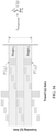
- a voxel matrix 87 is shown and is defined relative to a reference coordinate system with x, y, and z axes.
- the voxel matrix 87 comprises a plurality of three-dimensional volumetric pixels 90 ("voxels" for short).
- Each voxel 90 has indices i , j , and k, which respectively define its location within the voxel matrix 87 and along the x, y, and z axes.
- each voxel 90 has a length dx along the x-axis, a width dy along the y-axis, and a height dz along the z-axis, as shown in FIG. 4B .
- the voxels collectively define a cube structure with i max voxels along the x-axis, j max voxels along the y-axis and k max voxels along the z-axis.
- the index value i max is the maximum x-axis index value
- the index value j max is the maximum y-axis index value
- the index value k max is the maximum z-axis index value.
- FIG. 4A an image of a model three-dimensional object 78 is shown placed on the same reference coordinate system as the voxel matrix 87, thereby superimposing the voxel matrix over the object model 78.
- the model of the three-dimensional object is defined by three-dimensional object data comprising a plurality of three-dimensional object data items of the type described previously.
- the superimposition of the voxel matrix over the object model 78 is preferably carried out using mathematical equations but is depicted graphically in FIG. 4A for ease of understanding.
- the superimposition process yields voxel data representative of the three-dimensional object.
- the voxel data comprises sets of active voxels that are defined by their whole or partial intersection with the object model 78.
- the voxel data is then used to generate solidification energy source event data that determines the pattern of solidification energy supplied by linear solidification device 42 along the scanning (y) axis as it moves along the travel (x) axis.
- FIGS. 4C and 4D illustrate the intersection of active voxels at a particular z-axis location (z(k)) with the object model 78.
- the active voxels 92 are those voxels having any portion of their interior volume occupied by the object model 78.
- each voxel 90 in voxel matrix 87 may be evaluated to see if any portion of its interior volume intersects object model 78. This process yields a set of active voxels, each having defined x, y, and z coordinates and corresponding index values, i, j, and k. The active voxels may then be used to define solidification energy source event data. For example, referring to FIG.
- the scanning (y) axis length of the build envelope will be limited by the maximum length of solidification energy that can be provided by linear solidification device 42 along the scanning (y) axis, but may be smaller than that length as dictated by the build platform 44, 70 dimensions, the dimensions of the solidifiable material container 48, 65 or other considerations.
- the travel (x) axis length of the build envelope will be limited by the maximum distance of travel of linear solidification device 42, but may also be limited by similar considerations.
- FIGS. 5A and 5B depict a top view of a region of solidifiable material which includes a build envelope 102.
- the build envelope 102 defines the maximum area of solidification, and therefore, the maximum area of the three-dimensional object in the x-y plane.
- a build platform may be defined mathematically (and referred to as a "virtual build platform" 200 in FIGS. 14 and 15 ) by defining maximum scanning and travel axis locations within the coordinate system. For example, when string data comprising sets of time values are used to define when to activate or deactivate a solidification energy source, the time values will be defined relative to a reference time value which is the first location along the scanning (y) axis at which solidification may occur.
- the virtual build platform 200 will be mathematically positioned in a path generation reference frame 204 (described below) which defines the locations at which scanning is physically possible based on the linear solidification device 42, the container 48 ( FIG. 1A ) or the container 65 ( FIG. 1B ), the build platform 70, and their relative relationships to one another.
- the string data may then be adjusted to account for the location of the virtual build platform 200 within the path generation reference frame 204.
- the solidification energy source when a rotating polygonal mirror is used as a scanning device, if the solidification energy source remains activated, scan lines will be produced which have a minimum and maximum position along the scanning (y) axis. These positions comprise the scanning (y) axis maximum and minimum locations of the path generation reference frame 204, and the build envelope of the apparatus.
- the solidification energy source event data may be defined so that the solidification energy source is never activated before a first location along the scanning axis is reached. This location will comprise the location of the virtual build platform 200 border 206 within the path generation reference frame.
- the location is determined by determining where in the path generation frame 204 the virtual build platform 200 will be located, and then determining the scanning time required to reach it from the scanning axis border 201 of the path generation reference frame 204.
- the string data defined for the virtual build platform 200 may then be shifted by that scanning time.
- the linear solidification device 42 is movable along the travel (x) axis along a total distance that equals the sum of a build envelope 102 travel (x) axis length L and two offset distances, ⁇ L and ⁇ R .
- the offset distances ⁇ L and ⁇ R respectively represent the distance from the left end-of-travel (EOT) position of linear solidification device 42 to the left-hand side build envelope boundary 103 and the distance from the right-hand side EOT position to the right-hand side build envelope boundary 105.
- the offset distances, ⁇ L and ⁇ R are provided to ensure that the linear solidification device 42 has time to achieve a substantially constant speed in the travel (x) axis direction before any solidification of solidifiable material will begin (i.e., before build envelope 102 is reached).
- the movement of the linear solidification device 42 at a constant travel (x) axis speed avoids the necessity of directly measuring the travel (x) axis position at any given moment because it allows a motor movement parameter for a linear solidification device travel axis translation motor (not shown) to provide an indirect indication of x-axis position.
- the motor movement parameter is a number of motor steps.
- ⁇ L and ⁇ R are equal.
- Travel (x) axis end of travel sensor 106 may also be provided to generate a signal indicating the linear solidification device 42 has reached an end-of-travel position along the travel (x) axis.
- the active voxels at each build (z) axis location correspond to scan lines 108 along which the linear solidification device 42 may selectively provide solidification energy within build envelope 102.
- scan lines 108 are shown mapped onto build envelope 102 in FIG. 5B .
- Each scan line 108 may be assigned a scan line index ranging in value from 1 to n max .
- the maximum length of each scan line 108 is defined by the distance between the build envelope scanning axis borders 104 and 107.
- the scan lines are arranged adjacent to one another starting at a build envelope travel axis border 103 and ending at build envelope travel axis border 105.
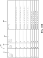
- FIG. 5C provides a table that illustrates an example of solidification energy source event data in the form of CPU tick values that are provided in data strings.
- the string index value is the same as the scan line index value.
- a computer memory index m 110 which is used to uniquely identify only those data strings that include solidification energy source event data (i.e., only those data strings for locations along the travel (x) axis where solidification will actually occur).
- Each set of data strings depicted in FIG. 5C has a start code which is represented in hexadecimal notation by a series of eight Fs. Going from left to right, the string index n for the data string is next. Following the string index, a series of solidification time values is provided. Each solidification time value defines the occurrence of a solidification energy source energization event. In one example, the energization states are ON or OFF.
- the solidification time values may take a variety of forms. However, in one implementation they are defined as elapsed times of a CPU clock in microcontroller unit used to operate the system for making a three-dimensional object. In one example, the CPU has a clock speed of 66MHz and the units of time are CPU ticks.
- the maximum scan length of each line in the scanning axis corresponds to 66,000 ticks.
- a timer is provided (such as a software timer programmed into the microcontroller unit) which is reset at the beginning of each linear scan, and the beginning of each linear scan is synchronized to the build envelope scanning axis boundary 104.
- ticks are defined relative to a zero starting time when the timer is reset at which point the line scanning operation is at the scanning axis build envelope boundary 104.
- the ticks may be defined relative to a zero starting time at which point the line scanning operation is at a path generation reference frame border 201 as discussed below with respect to FIGS. 13-15 )
- the systems 40 and 43 for making a three-dimensional object from a solidifiable material may include a non-transitory computer readable medium (i.e., a hard disk drive or a removable non-transitory medium such as a DVD) having computer executable instructions stored on it.
- the systems 40 and 43 may also include one or more processors and one or more microcontrollers.
- the one or more microcontrollers are configured to receive instructions from the one or more processors and to selectively activate and deactivate a source of solidification energy to cause the linear solidification device to selectively supply solidification energy along the scanning (y) axis in accordance with solidification energy source event data.
- the computer executable instructions When executed by one of the processors, the computer executable instructions generate voxel data from the three-dimensional object data. In preferred examples, the computer executable instructions further generate solidification energy source event data from the voxel data.
- the solidification energy source event data is compensated to account for the variation in scanning length per unit time (which is referred to as the "tick size" when CPU ticks are used as the scanning time measurement) and the scan length offset caused by the relative variation between solidification length and scanning length.
- FIG. 6 illustrates an idealized depiction of the variation in solidification length offset as a function of scanning axis position.
- four points P 0 , P i , P i+1 , and P E are depicted which are infinitesimally small points along the exposed surface of a solidifiable, photocurable resin 50 at which solidification energy is incident.
- the solidifiable material 50 solidifies in the approximate shape of a rectangle 120 having a scanning axis length of 2 ⁇ 0 , wherein ⁇ 0 may be referred to as the "offset".
- Point Po is at the mid-point of the solidified length.
- the point Po corresponds to a scanning axis time value of T 0 which is defined relative to a CPU clock cycle's initial value of zero.
- solidification energy is received at a point P i along the surface of the solidifiable material 50 at a distance D i from point P 0 .
- the solidifiable material 50 solidifies in the approximate shape of a rectangle 122 having a length of 2 ⁇ i , with P i being at the mid-point of the solidified length.
- solidification energy is received at a point P i+1 along the surface of the solidifiable material.
- the solidified material 50 solidifies in the approximate shape of a rectangle 124 having a length of 2 ⁇ i+1 with the point P i+i being at the mid-point.
- Point Pi+i is spaced apart from point P i by a distance d i+1 .
- FIG. 6 indicates, if solidification energy were received at these two adjacent points P i and P i+1 , their solidification lengths would overlap because of their offsets ⁇ i and ⁇ i+1 .
- solidification energy is received at point P E on the solidifiable material 50 and solidifies in the approximate shape of a rectangle having a length of 2 ⁇ E , with P E being at the mid-point.
- P E being at the mid-point.
- FIG. 6 if a shape is being solidified with a desired beginning point P 0 in a build envelope, activating a solidification energy source at time T 0 will produce an error in the as-built object because the starting point of the object will be offset from the point P 0 by an amount equal to ⁇ 0 .
- FIG. 7 graphically illustrates a method of accounting for the offsets to yield an object section having the desired dimensions.
- rectangle 136 is a solidified rectangular section 136 of solidifiable material 50 which would be produced by activating a linear solidification device solidification energy source (such as a laser diode) at an instant in time T 0 (e.g. a zero reference time for a CPU clock).
- the length A-B is the target length of a desired solidified rectangle 128 along the scanning (y) axis.
- Rectangle 138 is a solidified rectangular section of solidifiable material 50 which would be produced by activating a linear solidification device energy source at an instant in time T A (e.g., an elapsed time T A relative to a zero time of a CPU clock).
- the distance between the build envelope border 130 and the location at which solidification is intended to start 132 is OA. Based on the average scanning speed of the linear solidification device, a time value can be determined which corresponds to the distance OA. However, because of the offset ⁇ A , if that time value were used, the solidifiable material would extend beyond point 132.
- the time value at which solidification begins is shifted to the time corresponding to the location of point 132 plus the offset ⁇ A , which causes solidification to actually begin at point 132.
- the solidification energy source were deactivated at a time corresponding to point 134 relative to the time T 0 , solidification would extend beyond point 134 by the offset ⁇ B . Therefore, the solidification energy source is deactivated at a time corresponding to the location of point 134 minus the offset ⁇ B , which causes solidification to end at point 134.
- FIG. 6 and 7 illustrate an idealized case in which solidification energy can be projected instantaneously to a single point along solidifiable material 50 which then solidifies to a length along the scanning axis.
- the time values used to determine when to activate and deactivate a solidification energy source are integers, and the minimum time increment for turning the solidification energy source on and off is 1 time unit, e.g., 1 CPU tick if a CPU clock cycle is used.
- 1 time unit e.g. 1 CPU tick if a CPU clock cycle is used.
- solidification energy source event data is adjusted to also account for this variation in scanning length per unit time.
- calibration objects are created to develop a function f(t) that relates scanning lengths per unit time to position (or scanning time) along the scanning axis and which can be used to determine the offset at a particular scanning axis location.
- FIG. 11A a method of forming a three-dimensional object using obtaining compensated and offset solidification energy source event data values, which are preferably time values, is depicted.
- a function f(t) is provided which relates the scanning axis length of incident solidification energy per unit of scanning time and the solidification scanning axis length per unit time to the scanning time. Methods of generating the function f(t) are described below with reference to FIG. 11B .
- d OM is the scanning axis length of incident solidification energy ("scanning length") per unit time at scanning axis distance M from reference point O;
- the desired scanning axis distance (or target length) l OM from an initial scanning axis position O to a position M at which solidification is desired to begin or end may be related to an "uncompensated time value" T M (CPU ticks).
- the uncompensated time value assumes that the scanning length per unit time remains constant at its average value d u along the entire scanning axis.
- a polygonal mirror is used as a linear scanning device
- the solidification energy source e.g., laser diode
- a number of scan lines will be generated which equals the number of facets of the polygonal mirror.
- the length of the scan lines will equal SL LMAX .
- the compensated and offset time value T M is a function of a compensated but not offset time value T M , which has a corresponding offset value ⁇ M .
- Equation (8) or (9) it is useful to define a function G that relates desired scanning axis solidification energy positions ⁇ y to compensated time (but not offset) time values T (CPU ticks) and scanning axis solidification positons to compensated and offset time values T .
- T compensated time value
- T ⁇ G Tx d u
- Tx d u ⁇ y ⁇ 1 T ⁇
- T is a compensated, but not offset time value (CPU ticks)
- G is an inverse function, defined by a solution of an equation such as equations (6) or (8) and is itself a function of an uncompensated time value T (CPU ticks) and an average scanning axis scanning speed d u (microns/CPU tick).
- the offset ⁇ is a function of the compensated but not offset time value T .
- G is an inverse function, defined by a solution of an equation (such as equations (6) or (7)) relating a sum of refined and adjusted calibration object lengths (microns) to scanning axis time values (CPU ticks).
- equation (5) may be used to calculate uncompensated time values T from desired solidification positions l along the scanning axis and the average scanning time d u .
- compensated but not offset time values T 1 and T 2 are calculated which correspond to each uncompensated time value T at which a solidification energy source activation event T 1 or deactivation event T 2 , respectively occurs.
- equations (8) or (9) are used to determine the respective compensated but not offset time values T 1 and T 2 .
- offset values ⁇ 1 and ⁇ 2 are determined for each solidification energy source energization event based on their respective compensated but not offset time values T 1 and T 2 .
- a database such as the one exemplified in Table 300 of FIG. 12 may be used to relate compensated but not offset time values T to a scanning axis range j and an offset value ⁇ (j) within that scanning axis range.
- compensated and offset time values T 1 and T 2 are determined for each solidification source activation event and deactivation event, respectively using equations (6) or (7).
- the compensated and offset time values are used by a controller to selectively activate and deactivate a solidification energy source, such as a laser diode in optical communication with a linear scanning device such as a rotating polygonal mirror or a linear scanning micromirror, thereby forming the three-dimensional object.
- the scanning length function f(t) defines this relationship.
- the scanning length function f(t) is determined by solidifying calibration objects at various locations along the scanning (y) axis and using the measured scanning axis dimensions of the calibration objects to define the scanning length function f(t) and to determine offset values ⁇ .
- An exemplary method of developing the function f(t) is depicted in FIG. 11B .
- three-dimensional object data for a plurality of sets of calibration objects is provided and is used to solidify a solidifiable material into the calibration objects.
- the scanning (y) axis is divided into a plurality of scanning time ranges, each having a unique range index value j, and each range is further divided into sub-ranges, each sub-range having a sub-range index value i.
- the calibration objects are grouped into sets, wherein each set occupies a range and comprises a large object and a plurality of small objects.
- the small calibration parts are preferably defined by sets of uncompensated time values that define a continuous, uninterrupted set of uncompensated time values along the scanning axis.
- the large calibration parts preferably cover a continuous, and uninterrupted range of uncompensated time values along the scanning axis.
- the resulting small calibration parts would appear as in FIG. 8 and cover the entire set of scanning axis ranges without overlapping and without discontinuities. However, due to the offsets and variations in scanning length per unit time, that is typically not the case. The same is true for the large calibration parts.
- Each large calibration part is preferably defined by a set of uncompensated time values that is continuous within its range and which covers the entirety of the range.
- the small calibration parts within a given range are preferably defined by a set of uncompensated time values that are continuous within their range and which cover the entirety of that range.
- FIG. 8 Exemplary groupings of small and large calibration objects into sets are shown in FIG. 8 .
- a build envelope 107 is depicted in which a plurality of small calibration objects 220a-c, 222a-c, 224a-c, 226a-c, 228a-c, 230a-c, 232a-c, and 234a-c and large calibration objects 220d, 222d, 224d, 226d, 228d, 230d, 232d, and 234d are depicted.
- Small calibration objects 220a-220c are defined by a continuous range of the scanning axis within range 1, with each small calibration object 220a-220c occupying its own distinct sub-range.
- small calibration object 220a is in sub-range 1 of range 1
- small calibration object 220b is in sub-range 2 of range 1
- small calibration object 220c is in sub-range 3 of range 1.
- the large calibration object 220d extends the entire length of range 1. The remaining sets of small and large calibration objects are configured similarly.
- the depictions of the small and large calibration objects in FIGS. 8 are idealized and are used to generate uncompensated time values in accordance with equations (4) and (5).
- Each small test calibration object has an ideal or target length l (j,i) based on its object data.
- Each large calibration object has an ideal length L(j).
- the average scanning length per unit time d u may be determined in accordance with equation (4) as described previously and used with equation (5) and lengths l(j, i) and L(j) to determine uncompensated time value pairs (Tb, Te) for each calibration object, with the first value (Tb) defining the time at which the solidification energy source is activated and the second value (Te) defining the time at which the solidification energy source is deactivated.
- each calibration object will also have an associated offset ⁇ .
- the small calibration objects are spaced apart from one another along the travel (x) axis and from the large calibration object along the travel (x) axis so that they do not fuse together (see e.g., small calibration objects 220a-220c and large calibration object 220d which are spaced apart from one another along the travel (x) axis).
- Range 8 between Range 7 and Range k, a number of additional ranges will be provided but have been omitted for ease of illustration. Those ranges that are depicted are merely exemplary. Although not shown in the figures, multiple sets of calibration objects may be provided within a given scanning axis range as long as they are spaced apart from one another along the travel (x) axis and spaced apart along the travel (x) axis from the set of calibration objects occupying the next sequential range along the scanning (y) axis. The use of such multiple sets of calibration objects within a given range can be used to ensure the statistical significance of the test results and to account for fluctuations and anomalies in the test object dimensions.
- FIG. 10A depicts exemplary uncompensated time value pairs that define the small and large calibration objects of FIG. 8 .
- Time value pairs for the first seven (7) scanning axis ranges of FIG. 8 are shown in table 250 of FIG. 10A .
- Eight travel (x) axis positions each correspond to one of the columns 262-276 and define the beginning travel (x) axis position at which one of the calibration objects begins.
- Column 262 includes the object data for small calibration objects 220a, 222a, 224a, and 226a.
- Column 264 includes the object data for small calibration objects 220b, 222b, 224b, and 226b.
- Column 266 includes the object data for small calibration objects 220c, 222c, 224c, and 226c.
- Column 268 includes the object data for large calibration objects 220d, 222d, 224d, and 226d.
- Column 270 includes the object data for small calibration objects 228a, 230a, and 232a.
- Column 272 includes the object data for small calibration objects 228b, 230b, and 232b.
- Column 274 includes the object data for small calibration objects 228c, 230c, and 232c.
- Column 276 includes the object data for large test objects 228d, 230d, and 232d.
- each column 262-276 pairs of time values are given.
- the first time value in each pair defines a time at which the solidification energy source (e.g., laser diode) of a linear solidification device is activated, and the second time value defines a time at which the solidification energy source is deactivated.
- These time values are configured so that solidification occurs continuously within each range j, albeit with the objects arranged in a staggered fashion along the travel (x) axis.
- object 220a is defined by time value pair T1, T2, which causes a solidification energy source to be activated at time T1 and deactivated at time T2 while the linear solidification device is a location x1 (and for some distance thereafter along the x-axis so that the object has a width along the x-axis).
- T1 time value pair
- T2 location x2 along the travel axis
- the solidification energy source is activated at time T2 and deactivated at time T3.
- the solidification energy source is activated at time T3 and deactivated at time T4.
- Each of these time values is an uncompensated time value that is determined based on the object layout shown in FIG.
- FIG. 10B depicts exemplary data strings based on FIG. 10A which are used to form the small and large calibration objects of FIG. 8 .
- Column 282 lists the computer memory index m for each data string, which identifies those strings that include solidification energy source event data in sequence.
- Column 284 lists a string index value n which corresponds to the travel axis (x) position shown in column 286.
- Column 288 includes the data strings themselves. Each data string includes a hexadecimal start code (FFFFFF), the string index value n, and a series of time values, each of which corresponds to a change in the energization state of the solidification energy source.
- FFFFFF hexadecimal start code
- the solidification energy source is activated at time T1, deactivated at time T2, activated at time T6, deaactivted at time T7, activated at time T12, deactivated at time T13, activated at time T18, and deactivated at time T19.
- the other data strings are used similarly at the other travel (x) axis positions listed in column 286.
- step 1036 the actual scanning axis lengths L'(j) of the large calibration objects are measured.
- step 1038 the actual scanning axis lengths l'(j, i) of the small calibration objects are measured.
- FIG. 9 An exemplary set of as-built small calibration objects 242-246 and a large calibration object 240 are shown in FIG. 9 .
- the objects correspond to idealized small calibration objects 220a-220c and idealized large calibration object 220d shown in FIG. 8 .
- Small calibration object 242 corresponds to sub-range 1 of range 1.
- the solidification energy source is activated at time T1 and deactivated at time T2 (along the travel axis length ⁇ x)
- the resulting rectangular block has a scanning axis length of l'(1,1).
- the expected length based on the time interval from T1 to T2 and the average scanning length per unit time d u is l(1,1).
- Each of the small calibration objects 242, 244, and 246 has an expected length l(j,i) and an actual length l'(j,i) where i is a sub-range index and j is a range index.
- the solidified objects are rectangular blocks, and the actual lengths l'(j,i) are determined using calipers or other suitable measurement techniques to measure the distance between their faces that are parallel to the x-z plane (i.e., perpendicular to the scanning (y) axis). As shown in FIG. 9 , the actual lengths of the objects differ from the ideal lengths by two times the offset.
- Both the scanning length per unit time d and the offset ⁇ may vary with scanning axis position.
- the offset ⁇ within each range j is constant (i.e., it is assumed that the offset does not vary among the sub-ranges i within a given range j).
- the adjusted small calibration object length l a (j,i) accounts for the portion of the measured part length l'(j,i) that differs from the ideal part length l(j,i) due to the variation in scanning length per unit time, whereas the offset ⁇ (j) accounts for the variation in solidified length versus scanned length.
- the foregoing calculations are premised on the assumption that the offset ⁇ (j) is constant throughout each scanning axis range j. If this assumption were entirely valid, as shown in FIG.
- Equation (14) can be subtracted from the left-hand side to calculate a proportionate error ⁇ (j b ,j e ) over the continuous range interval j b to j e .
- the proportionate error is then used to calculate a refined adjusted length l ra( j,i).
- the proportionate error over the h consecutive scanning axis ranges is distributed to the ranges lying within j b to j e to arrive at the refined adjusted length l ra (j,i).
- the proportionate error for each unit of scanning time e.g., CPU tick
- ⁇ ⁇ j b j e ⁇ j b j e T j e ⁇ T j e
- the uncompensated time values T, compensated time values T , and compensated and offset time values T described above are defined relative to a zero time that defines the scanning axis border of an actual, physical build envelope or path generation reference frame.
- the area occupied by an object or set of objects being built is often less than the area defined by the path generation reference frame and can be described as a "virtual build platform" 200 ( FIG. 15 ). If the compensated and offset time values as previously described up to this point were used, the virtual build platform 200 would be effectively located at the scanning axis border 201 of the path generation reference frame 204 as illustrated by the solid rectangle in FIG.
- the time values are defined relative to a time value of zero at which the solidification energy (e.g., laser spot) strikes the path generation reference frame border 201).
- the solidification energy e.g., laser spot
- Actual three-dimensional object forming apparatuses that use linear solidification devices comprising a laser diode and a rotating polygonal mirror will also have scanning axis shift (identified as SHIFT in FIG.
- the shifting of the virtual build platform is carried out by shifting the time values used to direct the selective activation of the solidification energy source in the linear solidification device so that the scanning axis border of the virtual build platform 206 is shifted relative to the scanning axis border 201 of the path generation reference frame.
- step 1054 time values are calculated that are used to determine the time value ranges and sub-ranges used to define the step function f(t).
- the objects are designed with a specific scanning axis length, target_bar_size.
- the value of N small should correspond to the difference in the values of the members of each time value pair shown in FIG. 10A for the small calibration objects (e.g., T2-T1, T3-T2, etc.).
- a series of beginning (column 306a) and ending (column 306b) time values starting at T c0 can be generated which will define f(t).
- the difference between each beginning and ending time value in each row is N small .
- These time values can be related to the scanning axis index j and sub-index i values shown in FIG. 10A , as illustrated in FIG. 12 .
- This relation allows the refined and adjusted small calibration object lengths l ra (j,i) for each scanning axis range j and sub-range j to be related to the time values shown in columns 308a and 308b.
- the time values in columns 308a and 308b and the refined and adjusted small calibration object lengths l ra (j,i) in column 310 define the step function f(t).
- the inverse function defined by a solution to equation (8), which may be referred to as G( ⁇ )
- G( ⁇ ) is a mapping defined by the solution of integral equation (8).
- the rule of mapping G:X ⁇ G(X) is defined as follows: for a point X (which is a parameter in equation (8), G(X) is defined as the solution T M for equation (8).
- each range j has an offset value ⁇ (j) that is constant within the i sub-ranges of the range.
- the inverse function G(Txd u ) can be used to determine the compensated time values T 1 for activating the solidification energy source and compensated time values T 2 for deactivating the solidification energy source.
- Each compensated time value T 1 and T 2 can then be related to an offset value ⁇ (j) via Table 300 in FIG. 12 .
- 11A can be carried out by determining the value of the inverse function G(x), where x is the uncompensated time value T times the average scanning speed d u plus or minus the offset ⁇ , i.e., by determining G( T ⁇ ⁇ (j)), where + ⁇ (j) is used for solidification energy source activation (ON) events and - ⁇ (j) is used for solidification energy source deactivation (OFF) events.
- the method of generating solidification energy source event data involves a step of translating the three-dimensional object data from a reference coordinate system to a path generation reference frame 204.
- FIG. 13 is a flow chart describing one example method by which this process can be carried out. In the invention herein, the method of FIG. 13 is carried out to determine a reference scanning time value T c0 that is used to generate the step function f(t). In certain preferred examples, the method of FIG.
- the method of FIG. 13 uses a "path generation reference frame" with a travel (x) axis length equal to a scene size plus a margin and a scanning (y) axis length equal to the maximum possible scan length of the linear solidification device.
- a "scene” is a graphical representation of a defined area that includes one or more three-dimensional objects to be built during a given three-dimensional object manufacturing process.
- the scene size is the size of a bounding box that encompasses the objects comprising the scene and may not exceed the size of the build envelope.
- the method further defines a "virtual build platform" used to calculate solidification energy source event data values (e.g., CPU ticks) that will ultimately center the three-dimensional object at the scanning (y) axis mid-point of the linear solidification device 42 and the mid-point of the actual build envelope 104 (i.e., the mid-point between the scanning axis borders 104 and 107 of FIG. 5A .
- solidification energy source event data values e.g., CPU ticks
- the "path generation reference frame” is a reference coordinate system that relates voxel data to actual positions in a system for making three-dimensional objects, such as those illustrated in FIGS. 1A , 1B , and 8 .
- the actual positions can be related to uncompensated time values through the use of the average scanning axis scanning speed d u and equation (4).
- the scanning (y) axis length of the path generation reference frame equals the maximum length that solidification energy could traverse the scanning (y) axis based if solidification energy is projected along the entire length of any of the facets of a rotating polygonal mirror and deflected onto the travel axis/scanning axis plane.
- the origin and terminal points of the path generation reference frame will not necessarily be within build envelope 104 or even within the area of the travel axis/scanning axis plane where solidifiable material is located.
- systems and apparatuses suitable for use with the methods described herein include a build platform 44, 70 on which a three-dimensional object is progressively built and a linear solidification device 42 aligned with the build platform 44, 70 along the scanning (y) axis which is movable over along the travel (x) axis through the same travel (x) axis region occupied by the build platform 44, 70.
- the build platform 44, 70 includes the actual build envelope 102 of FIG. 5A and defines a maximum x-y area upon which a three-dimensional object may be built.
- FIG. 14 depicts an illustrative example of a virtual build platform 200 having a length L VX along the travel (x) axis and a length L VY along the scanning (y) axis. Images 202a-202c of models of three-dimensional objects defined by three-dimensional object data are positioned within the virtual build platform.
- FIG. 15 depicts an illustrative example of a path generation reference frame 204.
- the path generation reference frame 204 has a length along the scanning (y) axis of SL LMAX which is the maximum scan line length of the linear solidification device 42 along the scanning (y) axis.
- SL LMAX the maximum scan line length of the linear solidification device 42 along the scanning (y) axis.
- the border of the scanning axis border 104 of build envelope 102 (and the corresponding border 206 of the virtual build platform) will be spaced apart along the scanning (y) axis from the scanning axis border 201 of the path generation reference frame.
- the length of the build envelope 102 along the scanning (y) axis (and of the length of the virtual build envelope) will be less than the length SL LMAX of the path generation reference frame scanning axis.
- the value of SL LMAX can be determined by activating the solidification energy source 126 as the rotating energy deflector 120 rotates so that solidification energy is deflected off the entire length of at least one of the facets 122a-122f.
- the path generation reference frame has a maximum travel axis (x) length defined by the scene size plus a specified margin. As indicated previously, the scene size preferably does not exceed the size of the build envelope 102 along either the travel (x) or scanning (y) axis to ensure that the three-dimensional object(s) defined within the scene are built within the build envelope 102.
- the virtual build platform 200 is shown at three different path generation reference frame 204 locations (as indicated in threeboxes within the path generation reference frame 204) in FIG. 15 .
- Each box shows a different possible position of the virtual build platform 200 within path generation reference frame 204.
- the virtual build platform has a first scanning (y) axis border 206 along the path generation reference frame 204 scanning (y) axis and a second scanning (y) axis border 208 long the path generation reference frame 204 scanning (y) axis.
- the borders 206 and 208 are spaced apart by a fixed distance but will move to different scanning (y) axis locations within the path generation reference frame 204 when the virtual build platform 200 is repositioned within the path generation reference frame 204.
- each scan line would start at scanning axis border 201 and end at a location spaced apart from the scanning axis border 201 by SL LMAX .
- full length scan lines 108 FIG. 5B begin at scanning axis border 104 and end at scanning axis border 107 by appropriately adjusting the activation of solidification energy source 126.
- a virtual build platform 200 such as the one illustrated in FIG. 14 is defined with a travel axis length L VX and a scanning axis length L VY .
- the values of L vx and L vy are determined based on the dimensions of the build platform 44 and/or other hardware or software restrictions.
- an apparatus is provided with a linear solidification device mounted above a build platform such that 66,000 cpu ticks (theoretically) corresponds to a scanning (y) axis solidification length of 250mm.
- Lvy is less than or equal to 250mm.
- the working range of time values (CPU ticks) during which solidification along the scanning (y) axis is possible is 5000 to 50,000 CPU ticks.
- This range will limit Lvy to a value of about 170mm.
- Lvy is chosen to be close to this value and is set at 160mm.
- the memory of the control unit used to toggle the solidification energy source is also limited to 8MB, which constrains the number of solidification energy source events (e.g., toggle events) per layer.
- the memory restriction affects both Lvy and Lvy.
- Lvx is not limited by mechanical or hardware limitations, but rather, only by the memory limitation. Based on this limitation and the selected value of Lvy, Lvx is selected to be 250mm.
- step 1122 three-dimensional object data defining the three-dimensional object is provided and is placed within the virtual build platform 200.
- this is step is illustrated graphically in FIG. 14 , it is performed mathematically by relating the reference coordinate system that defines the three-dimensional object data (e.g., the STL file reference coordinate system) to the virtual build platform 200 reference coordinate system (e.g., the x-y axes in FIG. 14 ) and making the appropriate x, y translations of the three-dimensional object data. If the three-dimensional object data has been converted to uncompensated time values, equation (19) may be used.
- a path generation reference frame is defined with a scanning (y) axis length of SL LMAX and a travel (x) axis length equal to the scene size plus a margin.
- the virtual build platform 202 is then centered within the path generation reference frame 204 in step 1126. This is depicted graphically in FIG. 15 by the movement of the virtual build platform 200 shown in solid lines at the lower left-hand corner of the path generation reference frame 204 to the center of the path generation reference frame 204 as indicated by the upper box in dashed lines with the text "After Offsetting.”
- the use of the centering step 1126 helps ensure that the three-dimensional object(s) is produced within build envelope 102 ( FIG. 5A ).
- t 206 y 206 / d u
- t(206) the uncompensated solidification (scanning) time relative to a the beginning of a scan line at path generation reference frame border 201 (CPU ticks);
- offsetting step 1128 aids in ensuring that the three-dimensional object or objects within a given scene are built within build envelope 102 ( FIG. 5A ).
- step 1128 yields three-dimensional object data that is oriented within a virtual build platform 200 at a specific location within a path generation reference frame 204.
- Step 1128 can also be carried out to center the virtual build platform 200 using compensated and offset time values T as described previously with respect to step 1052 of FIG. 11B .
- point A is a location at which the solidified length is to begin and point B is the location at which the solidified length is to end.
- the solidified length has a dimension into the page along the x-axis which is not visible and is part of a three-dimensional object defined by voxel data.
- Scanning axis points A and B define scanning axis distances relative to a reference point O.
- the distance of point A from the reference point O is represented as l AO (microns or millimeters), and the distance of point B from the reference point O is represented as l BO .
- the compensated but not offset time values T A and T B are then determined using equations (3), (9)-(11) with the step function f(t) defined by FIG. 12 .
- the compensated but not offset time values will each correspond to respective ranges ja and j b .
- offsets ⁇ (j a ) and ⁇ (j b ) may be determined from FIG. 12 .
- the segment 138 represents the solidification length obtained when solidification is carried out at the scanning axis coordinate defined by point A plus the offset value ⁇ (j a ) (shown as e A in the figure).
- the offset value ⁇ (j a ) shown as e A in the figure.
- the solidifiable material solidifies in the positive direction by the amount ⁇ (j b ) so that solidification actually ends at point B.
- the length of segment 140 in FIG. 7 reflects (in an exaggerated way) the value of the scanning axis length/unit time function f(t) at point B.
Landscapes
- Chemical & Material Sciences (AREA)
- Engineering & Computer Science (AREA)
- Materials Engineering (AREA)
- Manufacturing & Machinery (AREA)
- Physics & Mathematics (AREA)
- Mechanical Engineering (AREA)
- Optics & Photonics (AREA)
- Heating, Cooling, Or Curing Plastics Or The Like In General (AREA)
Claims (4)
- Procédé de fabrication d'un objet tridimensionnel, comprenant :la fourniture des données d'objet représentant un objet tridimensionnel, les données d'objet définissant des emplacements dans un système de coordonnées de référence où se situe l'objet, le système de coordonnées de référence comprenant un axe de déplacement, un axe de balayage et un axe de construction ;la conversion des données d'objet en ensembles de valeurs de temps non compensées T, chaque ensemble de valeurs de temps non compensées correspondant à un emplacement le long de l'axe de construction, et chaque valeur de temps non compensée correspondant à un emplacement au niveau duquel la solidification commence ou se termine le long de l'axe de balayage ;la fourniture d'une fonction échelon f(t) qui relie la longueur de balayage par unité de temps d'un dispositif de solidification linéaire aux valeurs de temps de l'axe de balayage ;la détermination d'une valeur de temps compensée
T pour chaque valeur de temps non compensée T ; etla solidification d'un matériau solidifiable en traversant un dispositif de solidification linéaire comprenant une source d'énergie de solidification en communication optique avec un dispositif de balayage linéaire le long d'un axe de déplacement de trame de référence de génération de voie tout en activant et désactivant sélectivement la source d'énergie de solidification à des moments basés sur les valeurs de temps compenséesT , les valeurs de temps compenséesT étant déterminées selon les équations suivantes :
 f(t) étant une fonction échelon reliant la longueur de balayage de l'axe de balayage par unité de temps au temps de l'axe de balayage,Tc0 étant un temps de balayage de référence qui définit le temps de début de la fonction échelon f(t) et qui correspond à un bord d'axe de balayage de plate-forme de construction virtuelle dans la trame de référence de génération de voie ;Δy(T) étant la distance entre le bord de l'axe de balayage et l'emplacement de l'axe de balayage correspondant à la valeur de temps non compensée T, etΔt étant l'intervalle de temps définissant la fonction échelon f(t) ;
etla détermination des valeurs de décalage correspondant à chaque valeur de temps compenséeT à partir d'une base de données reliant des valeurs de décalage ε à des valeurs de temps compenséesT ;la détermination du fait de savoir si chaque valeur de temps compenséeT correspond à un événement d'activation de source d'énergie de solidification ou à un événement de désactivation de source d'énergie de solidification ;la détermination d'une valeur de temps compensée et décaléedu étant une vitesse de balayage moyenne le long de l'axe de balayage, et l'étape d'activation et de désactivation sélective d'une source d'énergie de solidification en communication optique avec un dispositif de balayage linéaire à des moments basés sur les valeurs de temps compenséesT correspondant à chaque valeur de temps non compensée selon les équations suivantes :
T = G(Txdu + ε) si T correspond à un événement d'activation de source d'énergie de solidification, etT = G(Txdu - ε) si T correspond à un événement de désactivation de la source d'énergie de solidification,T comprenant l'activation sélective de la source d'énergie de solidification au niveau des valeurs de temps compensées et décaléesT qui correspondent aux événements d'activation de la source d'énergie de solidification et de désactivation sélective de la source d'énergie de solidification au niveau des valeurs de temps compensées et décaléesT qui correspondent aux événements de désactivation de la source d'énergie de solidification. - Procédé selon la revendication 1, le bord d'axe de balayage étant un bord de plate-forme de construction virtuelle, et la plate-forme de construction virtuelle étant définie dans la trame de référence de génération de voie.
- Procédé selon la revendication 1 ou la revendication 2, comprenant en outre l'étape de détermination de la valeur du temps de balayage de référence Tc0 selon l'équation suivante :
 SLLMAX étant une longueur de balayage maximale le long de l'axe de balayage d'une trame de référence de génération de voie ;du étant une vitesse de balayage moyenne le long de l'axe de balayage ;TLMAX étant un temps de balayage nécessaire pour balayer une ligne d'énergie de solidification sur toute la longueur de balayage maximale SLLMAX ;
etSHIFT étant un décalage observé dans un emplacement d'axe de balayage de trame de référence de génération de voie au niveau duquel l'énergie de solidification frappe le matériau solidifiable lorsque la source d'énergie de solidification est activée de manière sélective au niveau d'une valeur de temps non compensée correspondant à un emplacement d'axe de balayage de trame de référence de génération de voie souhaité du bord d'axe de balayage de plate-forme de construction virtuelle par rapport à l'emplacement d'axe de balayage souhaité de la bordure d'axe de balayage de plate-forme de construction virtuelle. - Procédé selon la revendication 3, lorsque la bordure de l'axe de balayage de la plate-forme de construction virtuelle se trouve au niveau de l'emplacement de l'axe de balayage de trame de référence de génération de voie souhaité, la plate-forme de construction virtuelle étant centrée le long de l'axe de balayage de trame de référence de génération de voie.
Applications Claiming Priority (2)
| Application Number | Priority Date | Filing Date | Title |
|---|---|---|---|
| US14/695,711 US20160311160A1 (en) | 2015-04-24 | 2015-04-24 | Apparatus and method for forming three-dimensional objects using scanning axis compensation and dynamic offset |
| PCT/US2016/028761 WO2016172423A1 (fr) | 2015-04-24 | 2016-04-22 | Appareil et procédé pour former des objets tridimensionnels par compensation et décalage dynamique d'axe de balayage |
Publications (3)
| Publication Number | Publication Date |
|---|---|
| EP3285992A1 EP3285992A1 (fr) | 2018-02-28 |
| EP3285992A4 EP3285992A4 (fr) | 2019-05-08 |
| EP3285992B1 true EP3285992B1 (fr) | 2022-03-16 |
Family
ID=57144341
Family Applications (1)
| Application Number | Title | Priority Date | Filing Date |
|---|---|---|---|
| EP16783902.6A Active EP3285992B1 (fr) | 2015-04-24 | 2016-04-22 | Appareil et procédé pour former des objets tridimensionnels par compensation et décalage dynamique d'axe de balayage |
Country Status (4)
| Country | Link |
|---|---|
| US (1) | US20160311160A1 (fr) |
| EP (1) | EP3285992B1 (fr) |
| ES (1) | ES2918525T3 (fr) |
| WO (1) | WO2016172423A1 (fr) |
Families Citing this family (8)
| Publication number | Priority date | Publication date | Assignee | Title |
|---|---|---|---|---|
| US11919229B2 (en) | 2015-04-16 | 2024-03-05 | Lawrence Livermore National Security, Llc | Large area projection micro stereolithography |
| KR101826739B1 (ko) * | 2016-11-21 | 2018-02-08 | 주식회사 신도리코 | 선형 레이저 광원을 이용한 3차원 프린터 |
| US11167375B2 (en) | 2018-08-10 | 2021-11-09 | The Research Foundation For The State University Of New York | Additive manufacturing processes and additively manufactured products |
| US11679555B2 (en) | 2019-02-21 | 2023-06-20 | Sprintray, Inc. | Reservoir with substrate assembly for reducing separation forces in three-dimensional printing |
| EP3930987B1 (fr) | 2019-02-28 | 2023-01-25 | 3D Systems, Inc. | Système d'impression tridimensionnel à haute résolution |
| CN112276088A (zh) * | 2020-11-19 | 2021-01-29 | 成都天齐增材智造有限责任公司 | 3d打印激光均匀扫描的光路控制方法 |
| CN115041704B (zh) * | 2022-07-04 | 2023-06-27 | 爱司凯科技股份有限公司 | 一种3d扫描打印设备扫描运动路径规划方法及扫描方法 |
| CN116393815B (zh) * | 2023-06-07 | 2023-08-25 | 山东大学 | 一种考虑焊接倾斜角的激光扫描焊接方法 |
Family Cites Families (7)
| Publication number | Priority date | Publication date | Assignee | Title |
|---|---|---|---|---|
| US5059359A (en) * | 1988-04-18 | 1991-10-22 | 3 D Systems, Inc. | Methods and apparatus for production of three-dimensional objects by stereolithography |
| JPH11513328A (ja) * | 1995-09-27 | 1999-11-16 | スリーディー システムズ インコーポレーテッド | 選択積層造形システムにおけるデータ操作およびシステム制御の方法および装置 |
| CN101821081B (zh) * | 2007-08-23 | 2014-06-25 | 3D系统公司 | 利用激光扫描反射计的自动几何校准 |
| US8666142B2 (en) * | 2008-11-18 | 2014-03-04 | Global Filtration Systems | System and method for manufacturing |
| WO2014165643A2 (fr) | 2013-04-04 | 2014-10-09 | Global Filtration Systems, A Dba Of Gulf Filtration Systems Inc. | Appareil et procédé permettant de former des objets en trois dimensions à l'aide d'une solidification linéaire avec une correction d'axe de déplacement et une commande de puissance |
| WO2014199231A2 (fr) * | 2013-05-24 | 2014-12-18 | Looking Glass Hk Ltd. | Procédé de fabrication d'une représentation volumétrique physique d'un objet tridimensionnel virtuel |
| US9586364B2 (en) * | 2013-11-27 | 2017-03-07 | Global Filtration Systems | Apparatus and method for forming three-dimensional objects using linear solidification with contourless object data |
-
2015
- 2015-04-24 US US14/695,711 patent/US20160311160A1/en not_active Abandoned
-
2016
- 2016-04-22 WO PCT/US2016/028761 patent/WO2016172423A1/fr unknown
- 2016-04-22 ES ES16783902T patent/ES2918525T3/es active Active
- 2016-04-22 EP EP16783902.6A patent/EP3285992B1/fr active Active
Also Published As
| Publication number | Publication date |
|---|---|
| EP3285992A4 (fr) | 2019-05-08 |
| ES2918525T3 (es) | 2022-07-18 |
| US20160311160A1 (en) | 2016-10-27 |
| EP3285992A1 (fr) | 2018-02-28 |
| WO2016172423A1 (fr) | 2016-10-27 |
Similar Documents
| Publication | Publication Date | Title |
|---|---|---|
| EP3285992B1 (fr) | Appareil et procédé pour former des objets tridimensionnels par compensation et décalage dynamique d'axe de balayage | |
| US10005237B2 (en) | Apparatus and method for forming three-dimensional objects using linear solidification with contourless object data | |
| US10589507B2 (en) | Apparatus and method for forming three-dimensional objects using a curved build platform or curved solidification substrate | |
| EP2981402B1 (fr) | Procédé permettant de former des objets en trois dimensions à l'aide d'une solidification linéaire avec une correction d'axe de déplacement et une commande de puissance | |
| US10000023B2 (en) | Apparatus and method for forming three-dimensional objects using linear solidification | |
| US9981425B2 (en) | Apparatus and method for forming three-dimensional objects using linear solidification | |
| US9902112B2 (en) | Apparatus and method for forming three-dimensional objects using linear solidification and a vacuum blade | |
| US4961154A (en) | Three dimensional modelling apparatus | |
| EP2186625B1 (fr) | Procédé de fabrication d'un objet tridimensionnel | |
| CN104956672B (zh) | 三维对象构造 | |
| JP2006285262A (ja) | 低解像度投影画像を用いたソリッド・イメージングにおける不均一エッジの改善 | |
| EP2958719B1 (fr) | Procédé de formage d'objets tridimensionnels à l'aide de solidification linéaire | |
| WO2014006399A1 (fr) | Appareil de fabrication d'additif | |
| JP2009083240A (ja) | 光造形装置 | |
| EP3659783A1 (fr) | Procédé et dispositif de fabrication additive | |
| CN216506784U (zh) | 3d打印设备、系统及控制装置 | |
| JP2009160859A (ja) | 光造形装置および光造形方法、並びに光造形物 |
Legal Events
| Date | Code | Title | Description |
|---|---|---|---|
| STAA | Information on the status of an ep patent application or granted ep patent |
Free format text: STATUS: THE INTERNATIONAL PUBLICATION HAS BEEN MADE |
|
| PUAI | Public reference made under article 153(3) epc to a published international application that has entered the european phase |
Free format text: ORIGINAL CODE: 0009012 |
|
| STAA | Information on the status of an ep patent application or granted ep patent |
Free format text: STATUS: REQUEST FOR EXAMINATION WAS MADE |
|
| 17P | Request for examination filed |
Effective date: 20171124 |
|
| AK | Designated contracting states |
Kind code of ref document: A1 Designated state(s): AL AT BE BG CH CY CZ DE DK EE ES FI FR GB GR HR HU IE IS IT LI LT LU LV MC MK MT NL NO PL PT RO RS SE SI SK SM TR |
|
| AX | Request for extension of the european patent |
Extension state: BA ME |
|
| RIN1 | Information on inventor provided before grant (corrected) |
Inventor name: JANBAIN, MOHAMAD Inventor name: NAM, ALEXANDER |
|
| RIN1 | Information on inventor provided before grant (corrected) |
Inventor name: NAM, ALEXANDER Inventor name: JANBAIN, MOHAMAD |
|
| DAV | Request for validation of the european patent (deleted) | ||
| DAX | Request for extension of the european patent (deleted) | ||
| A4 | Supplementary search report drawn up and despatched |
Effective date: 20190408 |
|
| RIC1 | Information provided on ipc code assigned before grant |
Ipc: B29C 64/386 20170101AFI20190402BHEP |
|
| REG | Reference to a national code |
Ref country code: DE Ref legal event code: R079 Ref document number: 602016070086 Country of ref document: DE Free format text: PREVIOUS MAIN CLASS: B29C0067000000 Ipc: B33Y0010000000 |
|
| GRAP | Despatch of communication of intention to grant a patent |
Free format text: ORIGINAL CODE: EPIDOSNIGR1 |
|
| STAA | Information on the status of an ep patent application or granted ep patent |
Free format text: STATUS: GRANT OF PATENT IS INTENDED |
|
| RIC1 | Information provided on ipc code assigned before grant |
Ipc: B29C 64/393 20170101ALI20210930BHEP Ipc: B33Y 50/02 20150101ALI20210930BHEP Ipc: B33Y 30/00 20150101ALI20210930BHEP Ipc: B33Y 10/00 20150101AFI20210930BHEP |
|
| INTG | Intention to grant announced |
Effective date: 20211015 |
|
| GRAS | Grant fee paid |
Free format text: ORIGINAL CODE: EPIDOSNIGR3 |
|
| GRAA | (expected) grant |
Free format text: ORIGINAL CODE: 0009210 |
|
| STAA | Information on the status of an ep patent application or granted ep patent |
Free format text: STATUS: THE PATENT HAS BEEN GRANTED |
|
| AK | Designated contracting states |
Kind code of ref document: B1 Designated state(s): AL AT BE BG CH CY CZ DE DK EE ES FI FR GB GR HR HU IE IS IT LI LT LU LV MC MK MT NL NO PL PT RO RS SE SI SK SM TR |
|
| REG | Reference to a national code |
Ref country code: GB Ref legal event code: FG4D |
|
| REG | Reference to a national code |
Ref country code: CH Ref legal event code: EP |
|
| REG | Reference to a national code |
Ref country code: DE Ref legal event code: R096 Ref document number: 602016070086 Country of ref document: DE |
|
| REG | Reference to a national code |
Ref country code: IE Ref legal event code: FG4D |
|
| REG | Reference to a national code |
Ref country code: AT Ref legal event code: REF Ref document number: 1475609 Country of ref document: AT Kind code of ref document: T Effective date: 20220415 |
|
| REG | Reference to a national code |
Ref country code: LT Ref legal event code: MG9D |
|
| REG | Reference to a national code |
Ref country code: ES Ref legal event code: FG2A Ref document number: 2918525 Country of ref document: ES Kind code of ref document: T3 Effective date: 20220718 |
|
| REG | Reference to a national code |
Ref country code: NL Ref legal event code: MP Effective date: 20220316 |
|
| PG25 | Lapsed in a contracting state [announced via postgrant information from national office to epo] |
Ref country code: SE Free format text: LAPSE BECAUSE OF FAILURE TO SUBMIT A TRANSLATION OF THE DESCRIPTION OR TO PAY THE FEE WITHIN THE PRESCRIBED TIME-LIMIT Effective date: 20220316 Ref country code: RS Free format text: LAPSE BECAUSE OF FAILURE TO SUBMIT A TRANSLATION OF THE DESCRIPTION OR TO PAY THE FEE WITHIN THE PRESCRIBED TIME-LIMIT Effective date: 20220316 Ref country code: NO Free format text: LAPSE BECAUSE OF FAILURE TO SUBMIT A TRANSLATION OF THE DESCRIPTION OR TO PAY THE FEE WITHIN THE PRESCRIBED TIME-LIMIT Effective date: 20220616 Ref country code: LT Free format text: LAPSE BECAUSE OF FAILURE TO SUBMIT A TRANSLATION OF THE DESCRIPTION OR TO PAY THE FEE WITHIN THE PRESCRIBED TIME-LIMIT Effective date: 20220316 Ref country code: HR Free format text: LAPSE BECAUSE OF FAILURE TO SUBMIT A TRANSLATION OF THE DESCRIPTION OR TO PAY THE FEE WITHIN THE PRESCRIBED TIME-LIMIT Effective date: 20220316 Ref country code: BG Free format text: LAPSE BECAUSE OF FAILURE TO SUBMIT A TRANSLATION OF THE DESCRIPTION OR TO PAY THE FEE WITHIN THE PRESCRIBED TIME-LIMIT Effective date: 20220616 |
|
| REG | Reference to a national code |
Ref country code: AT Ref legal event code: MK05 Ref document number: 1475609 Country of ref document: AT Kind code of ref document: T Effective date: 20220316 |
|
| PG25 | Lapsed in a contracting state [announced via postgrant information from national office to epo] |
Ref country code: LV Free format text: LAPSE BECAUSE OF FAILURE TO SUBMIT A TRANSLATION OF THE DESCRIPTION OR TO PAY THE FEE WITHIN THE PRESCRIBED TIME-LIMIT Effective date: 20220316 Ref country code: GR Free format text: LAPSE BECAUSE OF FAILURE TO SUBMIT A TRANSLATION OF THE DESCRIPTION OR TO PAY THE FEE WITHIN THE PRESCRIBED TIME-LIMIT Effective date: 20220617 Ref country code: FI Free format text: LAPSE BECAUSE OF FAILURE TO SUBMIT A TRANSLATION OF THE DESCRIPTION OR TO PAY THE FEE WITHIN THE PRESCRIBED TIME-LIMIT Effective date: 20220316 |
|
| PG25 | Lapsed in a contracting state [announced via postgrant information from national office to epo] |
Ref country code: NL Free format text: LAPSE BECAUSE OF FAILURE TO SUBMIT A TRANSLATION OF THE DESCRIPTION OR TO PAY THE FEE WITHIN THE PRESCRIBED TIME-LIMIT Effective date: 20220316 |
|
| PG25 | Lapsed in a contracting state [announced via postgrant information from national office to epo] |
Ref country code: SM Free format text: LAPSE BECAUSE OF FAILURE TO SUBMIT A TRANSLATION OF THE DESCRIPTION OR TO PAY THE FEE WITHIN THE PRESCRIBED TIME-LIMIT Effective date: 20220316 Ref country code: SK Free format text: LAPSE BECAUSE OF FAILURE TO SUBMIT A TRANSLATION OF THE DESCRIPTION OR TO PAY THE FEE WITHIN THE PRESCRIBED TIME-LIMIT Effective date: 20220316 Ref country code: RO Free format text: LAPSE BECAUSE OF FAILURE TO SUBMIT A TRANSLATION OF THE DESCRIPTION OR TO PAY THE FEE WITHIN THE PRESCRIBED TIME-LIMIT Effective date: 20220316 Ref country code: PT Free format text: LAPSE BECAUSE OF FAILURE TO SUBMIT A TRANSLATION OF THE DESCRIPTION OR TO PAY THE FEE WITHIN THE PRESCRIBED TIME-LIMIT Effective date: 20220718 Ref country code: EE Free format text: LAPSE BECAUSE OF FAILURE TO SUBMIT A TRANSLATION OF THE DESCRIPTION OR TO PAY THE FEE WITHIN THE PRESCRIBED TIME-LIMIT Effective date: 20220316 Ref country code: CZ Free format text: LAPSE BECAUSE OF FAILURE TO SUBMIT A TRANSLATION OF THE DESCRIPTION OR TO PAY THE FEE WITHIN THE PRESCRIBED TIME-LIMIT Effective date: 20220316 Ref country code: AT Free format text: LAPSE BECAUSE OF FAILURE TO SUBMIT A TRANSLATION OF THE DESCRIPTION OR TO PAY THE FEE WITHIN THE PRESCRIBED TIME-LIMIT Effective date: 20220316 |
|
| PG25 | Lapsed in a contracting state [announced via postgrant information from national office to epo] |
Ref country code: PL Free format text: LAPSE BECAUSE OF FAILURE TO SUBMIT A TRANSLATION OF THE DESCRIPTION OR TO PAY THE FEE WITHIN THE PRESCRIBED TIME-LIMIT Effective date: 20220316 Ref country code: IS Free format text: LAPSE BECAUSE OF FAILURE TO SUBMIT A TRANSLATION OF THE DESCRIPTION OR TO PAY THE FEE WITHIN THE PRESCRIBED TIME-LIMIT Effective date: 20220716 Ref country code: AL Free format text: LAPSE BECAUSE OF FAILURE TO SUBMIT A TRANSLATION OF THE DESCRIPTION OR TO PAY THE FEE WITHIN THE PRESCRIBED TIME-LIMIT Effective date: 20220316 |
|
| REG | Reference to a national code |
Ref country code: CH Ref legal event code: PL |
|
| REG | Reference to a national code |
Ref country code: DE Ref legal event code: R097 Ref document number: 602016070086 Country of ref document: DE |
|
| REG | Reference to a national code |
Ref country code: BE Ref legal event code: MM Effective date: 20220430 |
|
| PLBE | No opposition filed within time limit |
Free format text: ORIGINAL CODE: 0009261 |
|
| STAA | Information on the status of an ep patent application or granted ep patent |
Free format text: STATUS: NO OPPOSITION FILED WITHIN TIME LIMIT |
|
| REG | Reference to a national code |
Ref country code: DE Ref legal event code: R082 Ref document number: 602016070086 Country of ref document: DE Representative=s name: PATENTANWAELTE KLUIN DEBELIUS WEBER PARTG MBB, DE |
|
| PG25 | Lapsed in a contracting state [announced via postgrant information from national office to epo] |
Ref country code: MC Free format text: LAPSE BECAUSE OF FAILURE TO SUBMIT A TRANSLATION OF THE DESCRIPTION OR TO PAY THE FEE WITHIN THE PRESCRIBED TIME-LIMIT Effective date: 20220316 Ref country code: LU Free format text: LAPSE BECAUSE OF NON-PAYMENT OF DUE FEES Effective date: 20220422 Ref country code: LI Free format text: LAPSE BECAUSE OF NON-PAYMENT OF DUE FEES Effective date: 20220430 Ref country code: DK Free format text: LAPSE BECAUSE OF FAILURE TO SUBMIT A TRANSLATION OF THE DESCRIPTION OR TO PAY THE FEE WITHIN THE PRESCRIBED TIME-LIMIT Effective date: 20220316 Ref country code: CH Free format text: LAPSE BECAUSE OF NON-PAYMENT OF DUE FEES Effective date: 20220430 |
|
| 26N | No opposition filed |
Effective date: 20221219 |
|
| PG25 | Lapsed in a contracting state [announced via postgrant information from national office to epo] |
Ref country code: SI Free format text: LAPSE BECAUSE OF FAILURE TO SUBMIT A TRANSLATION OF THE DESCRIPTION OR TO PAY THE FEE WITHIN THE PRESCRIBED TIME-LIMIT Effective date: 20220316 Ref country code: BE Free format text: LAPSE BECAUSE OF NON-PAYMENT OF DUE FEES Effective date: 20220430 |
|
| PG25 | Lapsed in a contracting state [announced via postgrant information from national office to epo] |
Ref country code: IE Free format text: LAPSE BECAUSE OF NON-PAYMENT OF DUE FEES Effective date: 20220422 |
|
| PG25 | Lapsed in a contracting state [announced via postgrant information from national office to epo] |
Ref country code: HU Free format text: LAPSE BECAUSE OF FAILURE TO SUBMIT A TRANSLATION OF THE DESCRIPTION OR TO PAY THE FEE WITHIN THE PRESCRIBED TIME-LIMIT; INVALID AB INITIO Effective date: 20160422 |
|
| PG25 | Lapsed in a contracting state [announced via postgrant information from national office to epo] |
Ref country code: MK Free format text: LAPSE BECAUSE OF FAILURE TO SUBMIT A TRANSLATION OF THE DESCRIPTION OR TO PAY THE FEE WITHIN THE PRESCRIBED TIME-LIMIT Effective date: 20220316 Ref country code: CY Free format text: LAPSE BECAUSE OF FAILURE TO SUBMIT A TRANSLATION OF THE DESCRIPTION OR TO PAY THE FEE WITHIN THE PRESCRIBED TIME-LIMIT Effective date: 20220316 |
|
| PG25 | Lapsed in a contracting state [announced via postgrant information from national office to epo] |
Ref country code: TR Free format text: LAPSE BECAUSE OF FAILURE TO SUBMIT A TRANSLATION OF THE DESCRIPTION OR TO PAY THE FEE WITHIN THE PRESCRIBED TIME-LIMIT Effective date: 20220316 |
|
| PGFP | Annual fee paid to national office [announced via postgrant information from national office to epo] |
Ref country code: GB Payment date: 20240419 Year of fee payment: 9 |
|
| PGFP | Annual fee paid to national office [announced via postgrant information from national office to epo] |
Ref country code: DE Payment date: 20240418 Year of fee payment: 9 |
|
| PGFP | Annual fee paid to national office [announced via postgrant information from national office to epo] |
Ref country code: ES Payment date: 20240503 Year of fee payment: 9 |
|
| PGFP | Annual fee paid to national office [announced via postgrant information from national office to epo] |
Ref country code: IT Payment date: 20240422 Year of fee payment: 9 Ref country code: FR Payment date: 20240425 Year of fee payment: 9 |