EP3285676B1 - Spannungsregulator für betätigungselemente und zugehörige fernbetätigte instrumente und systeme - Google Patents
Spannungsregulator für betätigungselemente und zugehörige fernbetätigte instrumente und systeme Download PDFInfo
- Publication number
- EP3285676B1 EP3285676B1 EP16783826.7A EP16783826A EP3285676B1 EP 3285676 B1 EP3285676 B1 EP 3285676B1 EP 16783826 A EP16783826 A EP 16783826A EP 3285676 B1 EP3285676 B1 EP 3285676B1
- Authority
- EP
- European Patent Office
- Prior art keywords
- actuation element
- actuation
- tension regulator
- slack
- tension
- Prior art date
- Legal status (The legal status is an assumption and is not a legal conclusion. Google has not performed a legal analysis and makes no representation as to the accuracy of the status listed.)
- Active
Links
- 230000007246 mechanism Effects 0.000 claims description 155
- 230000005540 biological transmission Effects 0.000 claims description 88
- 239000012636 effector Substances 0.000 claims description 40
- 230000033001 locomotion Effects 0.000 claims description 12
- 238000010276 construction Methods 0.000 claims description 10
- 239000002184 metal Substances 0.000 claims description 3
- 230000001154 acute effect Effects 0.000 claims description 2
- 230000004044 response Effects 0.000 claims description 2
- 210000000707 wrist Anatomy 0.000 description 14
- 230000005489 elastic deformation Effects 0.000 description 11
- 238000005381 potential energy Methods 0.000 description 8
- 238000001356 surgical procedure Methods 0.000 description 8
- 239000000463 material Substances 0.000 description 7
- 230000008878 coupling Effects 0.000 description 6
- 238000010168 coupling process Methods 0.000 description 6
- 238000005859 coupling reaction Methods 0.000 description 6
- 208000027418 Wounds and injury Diseases 0.000 description 5
- 230000008901 benefit Effects 0.000 description 5
- 230000008859 change Effects 0.000 description 5
- 238000000034 method Methods 0.000 description 3
- 230000001105 regulatory effect Effects 0.000 description 3
- 230000007704 transition Effects 0.000 description 3
- 238000005452 bending Methods 0.000 description 2
- 230000000694 effects Effects 0.000 description 2
- 239000013013 elastic material Substances 0.000 description 2
- 239000012530 fluid Substances 0.000 description 2
- 230000004907 flux Effects 0.000 description 2
- 238000003384 imaging method Methods 0.000 description 2
- 238000004519 manufacturing process Methods 0.000 description 2
- 230000004048 modification Effects 0.000 description 2
- 238000012986 modification Methods 0.000 description 2
- 229910001220 stainless steel Inorganic materials 0.000 description 2
- 239000010935 stainless steel Substances 0.000 description 2
- 210000002435 tendon Anatomy 0.000 description 2
- 230000009471 action Effects 0.000 description 1
- 239000008280 blood Substances 0.000 description 1
- 210000004369 blood Anatomy 0.000 description 1
- 238000006243 chemical reaction Methods 0.000 description 1
- 238000005520 cutting process Methods 0.000 description 1
- 238000013461 design Methods 0.000 description 1
- 238000010586 diagram Methods 0.000 description 1
- 230000006872 improvement Effects 0.000 description 1
- 208000014674 injury Diseases 0.000 description 1
- 238000005304 joining Methods 0.000 description 1
- 238000002324 minimally invasive surgery Methods 0.000 description 1
- 230000036316 preload Effects 0.000 description 1
- 230000008569 process Effects 0.000 description 1
- 238000011084 recovery Methods 0.000 description 1
- 230000002040 relaxant effect Effects 0.000 description 1
- 230000004043 responsiveness Effects 0.000 description 1
- 238000007493 shaping process Methods 0.000 description 1
- 238000013519 translation Methods 0.000 description 1
- 230000008733 trauma Effects 0.000 description 1
- 238000012800 visualization Methods 0.000 description 1
- 238000004804 winding Methods 0.000 description 1
Images


Classifications
-
- A—HUMAN NECESSITIES
- A61—MEDICAL OR VETERINARY SCIENCE; HYGIENE
- A61B—DIAGNOSIS; SURGERY; IDENTIFICATION
- A61B34/00—Computer-aided surgery; Manipulators or robots specially adapted for use in surgery
- A61B34/70—Manipulators specially adapted for use in surgery
- A61B34/71—Manipulators operated by drive cable mechanisms
-
- A—HUMAN NECESSITIES
- A61—MEDICAL OR VETERINARY SCIENCE; HYGIENE
- A61B—DIAGNOSIS; SURGERY; IDENTIFICATION
- A61B34/00—Computer-aided surgery; Manipulators or robots specially adapted for use in surgery
- A61B34/30—Surgical robots
-
- A—HUMAN NECESSITIES
- A61—MEDICAL OR VETERINARY SCIENCE; HYGIENE
- A61B—DIAGNOSIS; SURGERY; IDENTIFICATION
- A61B34/00—Computer-aided surgery; Manipulators or robots specially adapted for use in surgery
- A61B34/30—Surgical robots
- A61B34/35—Surgical robots for telesurgery
-
- B—PERFORMING OPERATIONS; TRANSPORTING
- B25—HAND TOOLS; PORTABLE POWER-DRIVEN TOOLS; MANIPULATORS
- B25J—MANIPULATORS; CHAMBERS PROVIDED WITH MANIPULATION DEVICES
- B25J9/00—Programme-controlled manipulators
- B25J9/10—Programme-controlled manipulators characterised by positioning means for manipulator elements
- B25J9/104—Programme-controlled manipulators characterised by positioning means for manipulator elements with cables, chains or ribbons
- B25J9/1045—Programme-controlled manipulators characterised by positioning means for manipulator elements with cables, chains or ribbons comprising tensioning means
-
- A—HUMAN NECESSITIES
- A61—MEDICAL OR VETERINARY SCIENCE; HYGIENE
- A61B—DIAGNOSIS; SURGERY; IDENTIFICATION
- A61B34/00—Computer-aided surgery; Manipulators or robots specially adapted for use in surgery
- A61B34/70—Manipulators specially adapted for use in surgery
- A61B34/71—Manipulators operated by drive cable mechanisms
- A61B2034/715—Cable tensioning mechanisms for removing slack
Definitions
- aspects of the present disclosure relate to regulate tension in actuation elements, for example, via one or more devices used in a force transmission mechanism including such actuation elements.
- aspects of the present disclosure relate to surgical instruments that are actuatable through a force transmission mechanism including one or more such tension regulating mechanisms.
- Benefits of minimally invasive surgery are well known, and they include less patient trauma, less blood loss, and faster recovery times when compared to traditional, open incision surgery.
- teleoperated surgical systems e.g., robotic systems that provide telepresence
- da Vinci ® Surgical System manufactured by Intuitive Surgical, Inc. of Sunnyvale, Calif is known.
- Such teleoperated surgical systems may allow a surgeon to operate with intuitive control and with precision.
- a surgical instrument may use a force transmission mechanism that receives drive inputs and transmits associated forces via actuation elements from a proximal end of the surgical instrument, along its shaft, to a distal portion of the surgical instrument.
- the actuation elements include tension members, such as cables, wires, or the like. Slack that may develop in such actuation elements can affect the transmission of force along such actuation elements. In addition, slack can lead to misalignment and/or derailment of actuation elements, such as, for example, at capstans or pulleys.
- WO 2016/006370 which is part of the state of the art for the purposes of novelty only, describes an end effector that executes a prescribed function; a motor unit that generates motive force that drives the end effector; a transmission member that is connected to the end effector and to the motor unit and that transmits motive force to the end effector; a tensile force generating unit; a tensile force maintaining unit that has a tension pulley that is connected to the tensile force generating unit and that is in contact with the transmission member, and that, by means of the movement of the tension pulley, maintains at a prescribed magnitude the tensile force that acts on the transmission member; and a switch that can hold the position of the tension pulley.
- US 2014/128849 describes a medical instrument including a shaft and an actuated structure mounted at a distal end of the shaft which can employ a pair of tendons connected to the actuated structure, extending down the shaft, and respectively wound around a capstan in opposite directions.
- a preload system may be coupled to maintain minimum tensions in the tendons.
- JP 2004 176532 describes a slack removing mechanism for chain suspended scaffolding . The mechanism is coupled to the chain through hooks and tension is regulated by the springs within the mechanism.
- Exemplary embodiments of the present disclosure may solve one or more of the above-mentioned problems and/or may demonstrate one or more of the above-mentioned desirable features. Other features and/or advantages may become apparent from the description that follows.
- the present invention provides a device to regulate tension of an actuation element for actuating movement of a surgical instrument, the device comprising: an elastically deformable body configured to be coupled to the actuation element such that the elastically deformable body translates with the actuation element; wherein the elastically deformable body is configured to elastically deform in response to a state of slack occurring in the actuation element; and wherein, as slack occurs in the actuation element, the elastically deformable body is configured to divert a path of the actuation element to accommodate the slack, the path differing from an axis of the actuation element prior to the actuation element developing slack.
- the present invention also provides a force transmission mechanism for a teleoperated surgical instrument, comprising: a chassis; an actuation input mechanism mounted to the chassis, wherein the actuation input mechanism is configured to receive forces from an actuation interface assembly of a teleoperated surgical system; an actuation element configured to transmit force sufficient to actuate an end effector of the surgical instrument; and a tension regulator comprising the elastically deformable body of claim 1 coupled to the actuation element to compensate for slack of the actuation element.
- a mechanism for compensating for slack in an actuation element of a surgical instrument comprises coupling a tension regulator comprising an elastically deformable body to the actuation element, and compensating for slack developing in the actuation element by diverting a path of the actuation element so the path of the actuation element differs from an axis the actuation element follows prior to the actuation element developing slack.
- spatially relative terms such as “beneath”, “below”, “lower”, “above”, “upper”, “proximal”, “distal”, and the like-may be used to describe one element's or feature's relationship to another element or feature as illustrated in the figures.
- These spatially relative terms are intended to encompass different positions (i.e., locations) and orientations (i.e., rotational placements) of a device in use or operation in addition to the position and orientation shown in the figures.
- orientations i.e., rotational placements
- the exemplary term “below” can encompass both positions and orientations of above and below.
- a device may be otherwise oriented (rotated 90 degrees or at other orientations) and the spatially relative descriptors used herein interpreted accordingly.
- the present disclosure contemplates force transmission mechanisms that include tension regulators that compensate for slack in actuation elements.
- the tension regulators accommodate for slack in a passive manner.
- tension regulators may utilize potential energy to passively compensate for slack.
- a tension regulator passively compensates for slack by changing its configuration or shape (e.g., via elastic deformation) as slack develops.
- Tension regulators of the various exemplary embodiments described herein may permit tension in an actuation element to be maintained without automated controls or manual adjustments, thus providing an efficient and robust means of regulating tension of an actuation element. Therefore, as an actuation element changes over time and develops slack, the tension regulator may compensate for slack and substantially maintain a desired tension in actuation element, as will be discussed below.
- an actuation element may follow a substantially straight path as it extends from a transmission mechanism and into the shaft of a surgical instrument.
- an actuation element is generally in a state of tension.
- a tension regulator coupled to the actuation element accommodates the slack by diverting a portion of the actuation element away from an initial path of the actuation element in its taut state.
- a tension regulator may form one or more bends in the actuation element such that a longitudinal axis of the actuation element is not straight at a location at which the tension regulator is disposed.
- a tension regulator may, therefore, accommodate slack by acting on the actuation element in the portion where slack occurs and exerting a force to maintain tension in that portion.
- a tension regulator coupled to the actuation element may pull an actuation element along a direction that is transverse (e.g., perpendicular) to an original path (e.g., straight path) of the portion of the actuation element, according to an exemplary embodiment. Diverting a portion of the length of the actuation element as the actuation element develops slack (i.e., loses tension), can serve to reestablish and maintain a tensioned, taut condition of the actuation element.
- a tension regulator may be configured to compensate (e.g., dynamically compensate) for varying amounts of slack (e.g., up to a maximum compensation amount the tension regulator is capable of), such as when the slack of an actuation element increases over time.
- a tension regulator may be coupled to an actuation element along a portion of the actuation element that is disposed within a force transmission mechanism of a surgical instrument.
- a tension regulator is coupled to the actuation element such that the tension regulator moves with the actuation element when the actuation element is actuated according to an exemplary embodiment.
- the tension regulator is configured to float with respect to the force transmission mechanism (e.g., move with the actuation element relative to the force transmission mechanism), whereas in other examples, the tension regulator may be fixed to a force transmission mechanism, such as a chassis of a force transmission mechanism.
- a tension regulator may be coupled to one or more of a plurality of actuation elements connected to an actuation input mechanism.
- tension regulators may be coupled to regulate tension in a single actuation element
- a tension regulator may be coupled so as to regulate tension in more than one actuation element simultaneously, according to an exemplary embodiment.
- a tension regulator may be a single piece of wire, a single piece of sheet metal, a single molded piece, a single band of elastic material, or other single piece constructions familiar to one of ordinary skill in the art.
- a portion of an actuation element extending through a tension regulator may be continuous length portion of the actuation element, according to an exemplary embodiment.
- the tension regulator may take up slack by acting on a portion of a length of the actuation element between ends of the actuation element, as opposed to, for example, acting on an end of the actuation element.
- a teleoperated surgical system may further include a surgeon console (not shown) for receiving input from a user to control instruments mounted at patient side cart 100.
- a teleoperated surgical system also can include an auxiliary control/vision cart (not shown), as described in, for example, U.S. Pub. No. US 2013/0325033, entitled “MultiPort Surgical Robotic System Architecture” and published on December 5, 2013 , and U.S. Pub. No. US 2013/0325031, entitled “Redundant Axis and Degree of Freedom for Hardware-Constrained Remote Center Robotic Manipulator” and published on December 5, 2013 .
- da Vinci ® Surgical System may be used, for example, with a da Vinci ® Surgical System, da Vinci ® Si Surgical System, Single Site da Vinci ® Surgical System, or a da Vinci ® Xi Surgical System, available from Intuitive Surgical, Inc.
- Patient side cart 100 may include a base 102, a main column 104, and a main boom 106 connected to main column 104.
- Patient side cart 100 may also include a plurality of manipulator arms 110, 111, 112, 113, which may each be connected to main boom 106.
- Manipulator arms 110, 111, 112, 113 may each include an instrument mount portion 120 to which an instrument 130 may be mounted, which is illustrated as being attached to manipulator arm 110. Portions of manipulator arms 110, 111, 112, 113 may be manipulated during a surgical procedure according to commands provided by a user at the surgeon console.
- signal(s) or input(s) transmitted from a surgeon console may be transmitted to the control/vision cart, which may interpret the input(s) and generate command(s) or output(s) to be transmitted to the patient side cart 100, for example through drive interface devices and ultimately to the surgical instrument transmission mechanism, to cause manipulation of an instrument 130 (only one such instrument being mounted in FIG. 1 ) and/or portions of manipulator arm 110 to which the instrument 130 is coupled at the patient side cart 100.
- Instrument mount portion 120 may comprise an actuation interface assembly 122 and a cannula mount 124, with a shaft 132 of instrument 130 extending through cannula mount 124 (and on to a surgery site during a surgical procedure) and a force transmission mechanism 134 of instrument 130 connecting with the actuation interface assembly 122, according to an exemplary embodiment.
- Cannula mount 124 may be configured to hold a cannula (not shown in FIG. 1 ) through which shaft 132 of instrument 130 may extend to a surgery site during a surgical procedure.
- Actuation interface assembly 122 may contain a variety of drive (e.g., input drive) and other mechanisms that are controlled to respond to input commands at the surgeon console and transmit forces to the force transmission mechanism 134 to actuate instrument 130, as those skilled in the art are familiar with, and thus can be broadly classified as a drive interface device.
- the input drives of actuation interface assembly 122 may directly engage with an interface structures (not shown) of force transmission mechanism 134 and transmit forces to force transmission mechanism 134, as will be discussed below.
- an instrument may be attached to any and each of manipulator arms 110, 111, 112, 113.
- An instrument 130 may be a surgical instrument with an end effector or may be an endoscopic imaging instrument or other sensing instrument utilized during a surgical procedure to provide information, (e.g., visualization, electrophysiological activity, pressure, fluid flow, and/or other sensed data) of a remote surgical site.
- a surgical instrument with an end effector or an imaging instrument may be attached to and used with any of manipulator arms 110, 111, 112, 113.
- the embodiments described herein are not limited to the exemplary embodiment of the patient side cart of FIG. 1 and various other teleoperated surgical system configurations, including patient side cart configurations, may be used with the exemplary embodiments described herein.
- FIG. 2 a schematic side view of an exemplary embodiment of a surgical instrument 200 is shown.
- surgical instrument 200 may be used as instrument 130 with the patient side cart 100 of the exemplary embodiment of FIG. 1 .
- Surgical instrument 200 may include a force transmission mechanism 210 (a chassis 211 for which is shown in the exemplary embodiment of FIG. 2 , with a housing being removed from the illustration so as reveal components of the force transmission mechanism 210 within), a shaft 222 connected to force transmission mechanism 210 at a proximal end 223 of shaft 222, a wrist 230 connected to a distal end 224 of shaft 222, and an end effector 220 connected to wrist 230.
- Shaft 222 may be flexible or rigid.
- shaft 222 may have a diameter ranging from about 3 mm to about 15 mm. According to another exemplary embodiment, the diameter of shaft 222 may range, for example, from about 5 mm to about 8 mm.
- End effector 220 may comprise, for example, forceps, a needle driver for suturing, cutting devices, dissecting devices, clip appliers, and other end effector configurations for performing various surgical procedures.
- Surgical instrument 200 may include one or more members to translate force between force transmission mechanism 210 and end effector 220 and/or between force transmission mechanism 210 and wrist 230.
- actuation elements 242, 244 may connect force transmission mechanism 210 to end effector 220 to provide actuation forces to end effector 220, such as by extending through an interior of shaft 222.
- force transmission mechanism 210 may actuate end effector 220 to control, for example, a jaw of end effector 220 (or other moveable part of end effector 220).
- actuation elements 242, 244 may be utilized to actuate wrist 230 in one or more degrees of freedom (e.g. pitch and/or yaw).
- Actuation elements 242, 244 may be in the form of tension members, such as when force transmission mechanism 210 is a pull-pull mechanism, as described in U.S. Patent No. 8,545,515 .
- Force transmission mechanism 210 may include one or more components to engage with a patient side cart 100 of a teleoperated surgical system to translate a force provided by patient side cart to surgical instrument 200.
- force transmission mechanism 210 may connect with the actuation interface assembly 122 of the patient side cart 100 of the exemplary embodiment of FIG. 1 so actuation interface assembly 122 may transmit forces to force transmission mechanism 210 to actuate instrument 200.
- force transmission mechanism 210 may include one or more driven actuation input mechanisms 212, 214 that engage (e.g., via a distal end of force transmission mechanism 210) with a manipulator of a patient side cart, such as actuation interface assembly 122 of patient side cart 100.
- actuation input mechanisms 212, 214 may interact with a manipulator of a patient side cart, such as actuation interface assembly 122 of patient side cart 100, via a sterile adapter (not shown), as will be described below.
- a manipulator of a patient side cart such as actuation interface assembly 122 of patient side cart 100
- a sterile adapter (not shown)
- One exemplary type of actuation input mechanism that can be used in force transmission mechanism 210 is a pull-pull mechanism, exemplary embodiments of which are described in U.S. Patent No. 8,545,515 .
- force transmission mechanism 210 may utilize a pull-pull mechanism
- actuation elements 242, 244 may be tension members
- driven actuation input mechanisms 212, 214 may be capstans that are rotationally driven by actuation interface assembly 122 to tension actuation elements 242, 244 to actuate instrument.
- driven actuation input mechanisms 212, 214 utilize actuation forces from an actuation interface assembly to actuate instrument 200.
- Force transmission mechanism 210 may include other components in addition to or in lieu of capstans to actuate various other functionalities of a surgical instrument, as those having ordinary skill in the art are familiar with.
- force transmission mechanism 210 may include other numbers of actuation input mechanisms 212, 214 than shown in the exemplary embodiment of FIG. 2 , such as, for example, one, three, four, five, six, seven, eight or more actuation input mechanisms.
- any number of actuation input mechanisms 212, 214 may be used, depending on the nature of a surgical instrument and depending upon the degrees of operational freedom of such an instrument.
- the force transmission mechanism of FIG. 2 provides an accurate conversion of rotational movement to translation movement of an actuation element for a surgical instrument of a teleoperated surgical system.
- actuation elements of a force transmission mechanism can experience a change in shape.
- actuation element 242 of the exemplary embodiment of FIG. 2 which may be a tension member, may deform, such as by stretching and increasing in length in proportion to a load delivered. As a result, actuation element 242 may develop slack.
- Actuation element 244 may move in coordination with actuation element 242 if both are coupled to a movement of the wrist 230 or end effector 220. With such coordinated movement, actuation element 244 also may develop slack.
- actuation element 242 could be in tension, with actuation element 244 having slack.
- the precision of force transmission mechanism 210 to actuate instrument 200 may diminish.
- rotation of driven actuation input mechanisms 212, 214 may need to be rotated to remove slack from actuation elements 242, 244 in order to place the actuation elements 242, 244 in a taut state in which they can actuate instrument 200.
- driven actuation input mechanisms 212, 214 may include a groove (not shown) in which the actuation elements 242, 244 normally lie during use of force transmission mechanism 210.
- Force transmission mechanism 310 may comprise a chassis 320 and a housing (not illustrated to reveal components of force transmission mechanism 310 within). Force transmission mechanism 310 may be used as transmission mechanism 134 of instrument 130 of the exemplary embodiment of FIG. 1 .
- force transmission mechanism 310 may comprise other components, such as, for example, a roll gear (not shown) to engage a proximal portion of a shaft (not shown) of an instrument and roll the shaft, such as shaft 222 of instrument 200 in the exemplary embodiment of FIG. 2 , flux conduits to deliver flux (e.g., electrical energy, fluids, suction, light, etc.) to an end effector of an instrument, and other components familiar to one of ordinary skill in the art.
- flux conduits to deliver flux (e.g., electrical energy, fluids, suction, light, etc.) to an end effector of an instrument, and other components familiar to one of ordinary skill in the art.
- Force transmission mechanism 310 may comprise one or more actuation input mechanisms 330, 332, as shown in the exemplary embodiment of FIG. 3 .
- actuation input mechanisms 330, 332 may be capstans, as discussed above with regard to actuation input mechanisms 212, 214 of the exemplary embodiment of FIG. 2 , although various other actuation input mechanism configurations may be used without departing from the scope of the present disclosure.
- Actuation elements may be respectively coupled to driven actuation input mechanisms 330, 332.
- actuation elements 340, 342 may be coupled to actuation input mechanism 330 and actuation elements 344, 346 may be coupled to actuation input mechanism 332, as shown in the exemplary embodiment of FIG. 3 .
- actuation elements 340, 342, 344, 346 may be tension members, such as cables, as described in U.S. Patent No. 8,545,515, issued October 1, 2013 .
- a pull-pull mechanism may include two tension members, with one tension member pulled to actuate an end effector or wrist in one direction and the other tension member pulled to actuate the end effector or wrist in another direction.
- a pull-pull mechanism may include a single tension element (e.g., a single tension element wrapped about a capstan or other actuator), with one portion of the tension element pulled to actuate an end effector or wrist in one direction and another portion of the tension member pulled to actuate the end effector or wrist in another direction.
- Chassis 320 of force transmission mechanism 310 may further comprise a chassis portion 322 that defines an exit aperture 324 into which actuation elements 340, 342, 344, 346 extend so actuation elements 340, 342, 344, 346 may be routed through a shaft (e.g., shaft 222 in FIG. 2 ) to a distal portion of an instrument, according to an exemplary embodiment.
- actuation elements connected to a driven actuation input mechanism may be formed by a single actuation element, according to an exemplary embodiment.
- actuation elements 340, 342 connected to actuation input mechanism 330 may be formed by a single actuation element, with actuation elements 340, 342 defined by two potions of the single actuation element that extend between force transmission mechanism 310 and a distal portion of an instrument.
- actuation elements 340, 342 may be portions of a single actuation element (e.g., cable) that loops about actuation input mechanism 330 at one end in force transmission mechanism, extends from force transmission mechanism 310 through the shaft of an instrument (e.g., shaft 222 in FIG.
- actuation input mechanism 330 is driven, such as by being rotated along the directions indicated by arrows 331 in the exemplary embodiment of FIG. 3 , one of the portions of the single actuation element (e.g., one of actuation elements 340, 342) is paid out from actuation input mechanism 330 while the other portion of the single actuation element (e.g., the other of actuation elements 340, 342) is taken up (e.g., wound upon) actuation input mechanism 330.
- Actuation elements 344, 346 connected to actuation input mechanism 332 may be similarly arranged.
- actuation elements 340, 342 may be two separate actuation elements.
- a first end of each of actuation elements 340, 342 may be connected to actuation input mechanism 330 and a second end of each of actuation elements 340, 342 may be connected to a distal portion of an instrument (e.g., wrist 230 or end effector 220).
- Actuation elements 344, 346 connected to actuation input mechanism 332 may be arranged as two separate actuation elements, according to an exemplary embodiment.
- actuation elements e.g., actuation elements 340, 342 in FIG. 3
- an actuation input mechanism e.g., actuation input mechanism 330 in FIG. 3
- tension regulators of the various exemplary embodiments described herein may be coupled to at least one actuation element of a force transmission mechanism either before or after the force transmission mechanism has been assembled.
- a tension regulator may be coupled to an actuation element after the actuation element has been connected to a wrist or end effector of an instrument (e.g., 230 or 220 in FIG. 2 ) and connected to an actuation input mechanism (e.g., 330 or 332 in FIG. 3 ).
- a tension regulator may be coupled to an actuation element and then the actuation element may be connected to a wrist or end effector of an instrument (e.g., 230 or 220 in FIG. 2 ) and connected to an actuation input mechanism (e.g., 330 or 332 in FIG. 3 ).
- tension regulator 350 is coupled to one or more actuation elements of force transmission mechanism 310 and be configured to passively compensate for slack in the one or more actuation elements.
- tension regulator 350 is uncoupled to chassis 320 of force transmission mechanism 310 and thus translates freely with an actuation element.
- tension regulator 350 Because of the way in which tension regulator 350 is coupled to an actuation element (e.g., one of actuation elements 340, 342, 344, 346), as the actuation element is wound upon or paid out from a respective actuation input mechanism (e.g., actuation input mechanism 330 or 332), such as along the directions indicated by arrows 370 in the exemplary embodiment of FIG. 3 , tension regulator 350 also moves along the directions indicated by arrows 370 relative to chassis 320.
- an actuation element e.g., one of actuation elements 340, 342, 344, 346
- actuation input mechanism e.g., actuation input mechanism 330 or 332
- tension regulator 350 is coupled to an actuation element.
- tension regulator 350 could impact the actuation input mechanism, or tension regulator 350 could impact chassis portion 322 defining aperture 324. Due to the size of force transmission mechanism 310 and the distance an actuation element travels between aperture 324 and an actuation input mechanism, a small space is provided for a tension regulator 350 to travel when coupled to an actuation element.
- a tension regulator 350 configured to be coupled to an actuation element may be designed to compensate for slack of the actuation element but also have a size small enough to minimize or eliminate impacts between the tension regulator 350 and chassis portion 322 or an actuation input mechanism.
- a tension regulator may be coupled to only one of the actuation elements connected to an actuation input mechanism (e.g., when actuation elements 340, 342 in FIG. 3 are defined by two actuation elements) or coupled to only one portion of a single actuation element that extends between a force transmission mechanism and a distal portion of an instrument (e.g., when actuation elements 340, 342 in FIG. 3 are portions of a single actuation element).
- the various exemplary embodiments described herein are not limited to such configurations and may instead have tension regulators coupled to more than one actuation element of a given actuation input mechanism.
- a tension regulator may be coupled to each actuation element for an actuation input mechanism. Coupling of tension regulators to actuation elements may be based upon, for example, a function of a component being actuated by the actuation elements, according to an exemplary embodiment.
- a tension regulator 350 may be coupled to actuation element 340 but not to actuation element 342.
- a tension regulator 350 is coupled to actuation element 344.
- actuation elements 342 and 346 may lack tension regulators 350, as shown in FIGS. 3 and 4 .
- slack is present in both paired actuation elements (e.g., actuation elements 340 and 342 or actuation elements 344 and 346)
- precise control of end effector elements can be improved by selectively accumulating the entire slack onto only one actuation element of a pair of actuation elements.
- all slack may be accumulated with a single tension regulator 350 coupled to one of actuation elements 340 and 342 or to one of actuation elements 344 and 346.
- all slack in paired actuation elements 340, 342 or in paired actuation elements 344, 346 accumulates in a tension regulator 350 coupled to one of the actuation elements (e.g., one of actuation elements 340, 342) of the respective pairing, while the other actuation element of the pairing (e.g., the other of actuation elements 340, 342) is drawn taut due to the removal of slack from the pair of actuation elements via the tension regulator 350. Because the other actuation element is taught and substantially straight, the length of the other actuation element is substantially known, which facilitates precise control of an element actuated by the actuation element.
- tension regulator 350 when tension regulator 350 is coupled to actuation element 340 and not to actuation element 342, the tension regulator 350 accumulates all slack of the paired actuation elements 340 and 342. In this way, actuation element 342 becomes taught, as indicated in FIG. 4 , and the length of actuation element 342 is substantially known.
- Actuation input mechanism 330 may be rotated (e.g., along directions 330) by an amount corresponding to the length of actuation element 342 in order to precisely control an end effector element actuated by actuation element 342.
- rotation of actuation input mechanism 330 does not necessarily provide precise control of an end effector element because the rotation of actuation input mechanism 330 is no longer matched to the length of actuation element.
- an amount of rotation of actuation input mechanism 330 no longer corresponds to a particular amount of paying out or winding up of actuation element 342 because slack is present in actuation element 342.
- a tension regulator 350 may be selectively coupled to an actuation element depending upon a function of the actuation element. Coupling a tension regulator 350 to an actuation element (e.g., actuation element 340) may result in the removal of slack between a pair of actuation elements (e.g., actuation elements 340, 342) and cause an actuation element of the pair that is not coupled to a tension regulator (e.g., actuation element 342) to become taut and straight, as indicated in FIG.
- an actuation element e.g., actuation element 340
- actuation element 340 While the other actuation element to which the tension regulator 350 is coupled (e.g., actuation element 340), is no longer straight in view of the function of the tension regulator 350 accumulating the slack. Because one actuation element (e.g., actuation element 342) is taut, its length is substantially known, which facilitates precise functioning of the actuation element, such as to operate an end effector by moving the actuation element an amount corresponding to its length. Conversely, the other actuation element (e.g., actuation element 340) is not straight and therefore it may be more difficult to use the other actuation element in a precise manner because of its length not being precisely known. In view of these considerations, one may select which actuation element, of a pair of actuation elements, to couple a tension regulator to based upon the function of the actuation element and how much precision is desirable when using the function of the actuation element.
- tension regulators 350 in FIGS. 3 and 4 may be coupled to actuation elements 340 and 344 that are pulled to actuate an end effector (e.g., end effector 220 in FIG. 2 ) to an open position, while not being coupled to actuation elements 342, 346 that are pulled to actuate the end effector to a closed position.
- Greater precision may be desirable, for example, for closing an end effector than opening the end effector, with coupling of the tension regulators 350 being selected in view of this consideration.
- slack is minimized or eliminated by coupling tension regulators 350 to actuation elements 340 and 344 because actuating the end effector to an open position may be accomplished with less precision and force than actuating the end effector to a closed position.
- actuation elements 342 and 346 may lack tension regulators 350 but are taut due to the removal of slack via the tension regulators 350 coupled to actuation elements 340, 344.
- the end effector may be effectively closed in an accurate manner with a desired amount of force by tensioning actuation elements 342, 346.
- a tension regulator may be coupled to each actuation element for an actuation input mechanism, as depicted in the exemplary embodiment of FIG. 5.
- FIG. 5 is a partial view of actuation elements 440 and 442 connected to a single actuation input mechanism (not shown), such as actuation input mechanism 330 or 332 in the exemplary embodiment of FIG. 3 .
- a tension regulator 450 is coupled to each of actuation elements 440 and 442, as shown in FIG. 5 .
- a single tension regulator may be coupled to an actuation element.
- the various exemplary embodiments described herein are not limited to a single actuation element being coupled to a particular actuation element.
- more than one tension regulator may be coupled to a particular actuation element.
- two, three, or more tension regulators may be coupled to a particular actuation element.
- Tension regulator 550 may be coupled to an actuation element, such as, for example, any of actuation elements 340, 342, 344, 346 of the exemplary embodiment of FIG. 3 .
- Tension regulator 550 may be made of, for example, stainless steel or other surgical instrument materials familiar to one of ordinary skill in the art.
- Tension regulator 550 may comprise a first leg 552 and a second leg 554 connected by a main loop 551.
- First leg 552 may be configured to move (e.g., in a rotational manner) relative to main loop 551, such as about the directions indicated by arrows 557 in the exemplary embodiment of FIG. 6 .
- Second leg 554 also may be configured to move (e.g., in a rotational manner) relative to main loop 551, such as about the directions indicated by arrows 559 in the exemplary embodiment of FIG. 6 .
- movement of legs 552, 554 may be accomplished via, for example, elastic deformation of tension regulator 550.
- Tension regulator 550 may further comprise end loops 553, 555 at each end of first and second legs 552, 554, as shown in FIG. 6 .
- Loops 551, 553, 555 may function to couple tension regulator 550 to an actuation element.
- an actuation element (not shown) may pass through each of loops 551, 553, 555 so tension regulator 550 is coupled to the actuation element.
- the loop configuration and illustrated in FIGS. 6-10 is intended to be exemplary and illustrative only, and it should be appreciated that various modifications can be made without departing from the scope of the present disclosure and claims.
- the direction (helical direction), pitch, and/or diameter may be modified, for example, to minimize any localized stress risers in the actuation element.
- the loop structures in the tension regulator of FIGS. 6-10 also may enable the tension regulator to be coupled to an actuation element already installed in a force transmission mechanism for an instrument.
- the rotation of the legs 552 and 554 about the main loop 551 transitions the tension regulator 550 between a configuration in which the tension regulator is approximately straight and a configuration in which the tension regulator is bent with a reduced angle (e.g., one or more acute angles or curves in the tension regulator) between the legs 552 and 554, according to an exemplary embodiment.
- bending of legs 552, 554, such as relative to main loop 551 may be accomplished via elastic deformation of tension regulator 550.
- the material from which the tension regulator 550 is made permits an elastic deformation of the tension regulator between the approximately straight and bent configurations, with the bent configuration being the state into which the tension regulator is biased (e.g., the low energy state of the tension regulator).
- tension regulator 550 may have a configuration intermediate the approximately straight configuration and the bent configuration depicted in FIG. 6 , depending upon the amount of force applied to tension regulator 550 by an actuation element the tension regulator 550 is coupled to.
- tension regulator 550 may be configured to divert an actuation element from a substantially straight path along a portion of its length as tension regulator 550 transitions from the approximately straight configuration, such as when the actuation element lacks slack, to the bent configuration of FIG. 6 as the actuation element develops slack.
- Tension regulator 550 may transition from the approximately straight configuration to the bent configuration via elastic deformation, which results in a dynamic change in the energy state of the tension regulator 550 (e.g., from a high energy state in its approximately straight configuration to a lower state in the bent configuration).
- tension regulator 550 may passively compensate for an increase in slack in actuation element.
- FIG. 8 depicts tension regulator 550, as described above with regard to FIGS. 6 and 7 , coupled to an actuation element 560.
- actuation element 560 may be routed through loops 551, 553, 555 of tension regulator 550 so tension regulator 550 is fastened to actuation element 560.
- a portion of actuation element 560 may extend through tension regulator 550 in a continuous, uninterrupted manner.
- tension regulator 550 there is no need to attach tension regulator 550 to an end of actuation element 560, or to attach tension regulator 550 to separate ends of actuation element (e.g., with the tension regulator connecting the separate ends of the actuation element). Further, if actuation element 560 is pulled along the directions indicated by arrows 570 in FIG. 8 , tension regulator 550 moves with actuation element 560, as described above with regard to the exemplary embodiment of FIG. 3 . When a large amount of motion of actuation element 560 occurs, such that loops 553 or 555 encounter chassis portion 327 or capstan 330 of FIG.
- tension regulator 550 may slidingly adjust to a new position on actuation element 560 rather than limit travel of actuation element 560.
- tension regulators may thus be relatively simply coupled to an actuation element already in an assembled state with the force transmission housing components by configuring tension members to be able to attach along a continuous length of the actuation element, as further described with respect to some exemplary embodiments below.
- actuation element 560 is taut, substantially straight, and essentially lacks slack (e.g., prior to developing slack). Due to its coupling with tension regulator 550, actuation element 560 applies a force to tension regulator 550, such as by extending actuation element 560 through loops 551, 553, 555. This causes first leg 552 and second leg 554 be pulled away from each other (e.g., via elastically deformation) in directions 557 and 559, such as relative to main loop 551. As a result, tension regulator 550 has an increased amount of potential energy due to its substantially straightened, elongated configuration shown in FIG.
- actuation element 560 pulls legs 552, 554 and also pulls main loop 551, such as along direction 574 relative to a straight axis 571 of actuation element 560 when actuation element is in the state shown in FIG. 8 .
- axis 571 may represent a path actuation element 560 follows when actuation element 560 is taut, substantially straight, and essentially lacks slack (e.g., prior to developing slack), as depicted in FIG. 8 .
- actuation element 560 may develop slack, such as, for example, due to deformation and elongation of actuation element 560.
- tension regulator 550 may compensate for the slack as the slack develops in actuation element 560.
- FIG. 9 tension regulator 550 and actuation element 560 are shown in state in which actuation element 560 has developed slack relative to the initial non-slack state shown in FIG. 8 .
- actuation element 560 becomes less taut and applies less force to tension regulator 550. This results in tension regulator 550 relaxing to a degree and becoming less elastically deformed relative to the state shown in FIG. 8 .
- first leg 552 may bend relative to main loop 551 in the direction indicated by arrow 557 in FIG. 9 and second leg 554 may bend relative to main loop 551 in the direction indicated by arrow 559 in FIG. 9 .
- First leg 552 and second leg 554 may bend until the slack has been removed and actuation element 560 is once again taut, as shown in FIG. 9 .
- tension regulator 550 may pull actuation element 560 along a direction indicated by arrows 572 in FIG. 9 , which is substantially perpendicular to the axis 571 of actuation element 560 as the actuation element 560 develops slack.
- main loop 551 may move along direction 572 in FIG. 9 and pull actuation element 560 locally relative to the axis 571 of actuation element 560 when actuation element is taut and substantially straight, as depicted in FIG. 8 .
- tension regulator 550 may compensate for slack in actuation element 560 via a dynamic change in the potential energy of tension regulator 550.
- actuation element 560 may be substantially straight when actuation element lacks slack.
- actuation element 560 may extend along a substantially straight path when actuation element 560 is taut and substantially straight, such as along axis 571 depicted in FIG. 8 .
- tension regulator 550 may compensate for the slack by diverting actuation element 560 from the straight path along axis 571.
- the portion of actuation element 560 extending through tension regulator 550 follows a path that diverges from the path extending along (e.g., is substantially coaxial to) longitudinal axis 571.
- tension regulator 550 may divert actuation element 560 along a path having an angle 575 of, for example, about 5 degrees to about 30 degrees when actuation element 560 develops slack.
- tension regulator 550 may accommodate the slack in actuation element 560 by increasing the path length of the actuation element 560 in a direction differing from the path along (e.g., substantially coaxial to) axis 571 of actuation element 560 when actuation element 560 is taut and substantially straight, as depicted in FIG. 8 .
- tension regulator 550 may accommodate an increase in length of actuation element 560 by pulling actuation element along a direction 572 that is substantially transverse (e.g., perpendicular) to the longitudinal axis 571 of actuation element 560.
- the portion of actuation element 560 extending through tension regulator 550 may follow a path having an angle 575 relative to axis 571 of actuation element 560 when actuation element 560 is taut and substantially straight, as depicted in FIG. 8 .
- Tension regulator 550 may be configured to compensate for varying amounts of slack in actuation element 560.
- the slack in actuation element 560 may further increase from the state shown in FIG. 9 to the exemplary embodiment shown in FIG. 10 .
- tension regulator 550 may relax further and become less elastically deformed relative to the state shown in FIG. 9 , so a change in potential energy of tension regulator 550 due to its deformation may be used to dynamically compensate for, and remove, the slack from actuation element 560.
- first leg 552 and second leg 554 may further bend along their respective directions with regard to main loop 551, with main loop 551 moving further along direction 572 with regard to axis 571.
- tension regulator 550 may pull actuation element 560 further along direction 572 and angle 575 for the path of the portion of actuation element 560 extending through tension regulator 550 may increase as the amount of slack increases. As a result, even as the slack of actuation element 560 increases, tension regulator 550 may continue to compensate for the slack and keep actuation element 560 substantially taut.
- Tension regulators of the exemplary embodiments described herein may have a maximum slack compensation amount.
- the maximum slack compensation amount may correspond to the amount of elastic deformation a tension regulator may undergo.
- tension regulator 550 may elastically deform an amount corresponding to the difference between the non-deformed state shown in FIG. 6 and the deformed shape shown in FIG. 8 , according to an exemplary embodiment.
- the amount of elastic deformation a tension regulator may undergo may be determined, at least in part, by the material of a tension regulator and geometry of a tension regulator, according to an exemplary embodiment.
- tension regulators of the exemplary embodiments described herein may be designed to apply a tension to an actuation element, such as in the states shown in the exemplary embodiments of FIGS. 9 and 10 , to remove slack but not apply an excessive amount of tension, which could overstress an actuation element.
- FIG. 11 a tension regulator 600 is shown coupled to an actuation element 620.
- Tension regulator 600 is fastened to actuation element 620 so that tension regulator 600 moves with actuation element 620, as described above with regard to the exemplary embodiment of FIG. 3 .
- FIG. 11 depicts tension regulator 600 in a non-deformed state.
- Tension regulator 600 may be made of, for example, stainless steel or other surgical instrument materials familiar to one of ordinary skill in the art.
- apex 606 may be shaped to resist actuation element 620 slipping off of apex 606.
- apex 606 may include projections 608 on lateral sides of actuation element 620, as shown in the exemplary embodiment of FIG. 11 .
- Tension regulator 600 may be coupled to actuation element 620 by threading actuation element 620 through holes 610 and 612 in a first leg 602, over an apex 606, and through holes 614 and 616 in a second leg 604 of tension regulator 600.
- first leg 602 and second leg 604 may be bent (e.g., elastically deformed) along respective directions 601 and 603 relative to apex 606 and apex 606 may be pulled along direction 605 relative to a longitudinal axis 624 of actuation element 620, as shown in the exemplary embodiment of FIG. 11 .
- tension regulator 600 may be increased and used to dynamically compensate for slack that develops in actuation element 620.
- actuation element 620 When actuation element 620 is taut and lacks slack, actuation element 620 may be substantially straight and follow a path extending along (e.g., substantially coaxial with) axis 624, as discussed above with regard to the exemplary embodiment of FIG. 8 .
- tension regulator 600 may divert actuation element 620 from the path along axis 624. For example, tension regulator 600 may divert the portion of actuation element 620 extending through tension regulator 600 along a path forming a non-zero angle 630 relative to axis 624.
- tension regulator 600 may accommodate slack in actuation element 620 by increasing the path length of actuation element 620.
- tension regulator 600 may pull actuation element 620 along a direction that is substantially transverse (e.g., perpendicular) to longitudinal axis 624.
- Tension regulator 700 may comprise a first leg 702 and a second leg 704, with contact portions 720, 722 at respective ends of first and second legs 702, 704.
- Tension regulator 700 may further comprise a main leg 706 including a contact portion 724.
- An actuation element (not shown) may be threaded, for example, over contact portions 720, 722 at ends of legs 702, 704 and under contact portion 724.
- first and second legs 702, 704 may be configured to bend (e.g., elastically deform) relative to main leg 706.
- first and second legs 702, 704 may include an area of material weakness, such as cutouts 708 and 710, to facilitate first and second legs 702, 704 bending relative to main leg 706, such as along directions 730 and 732 in the exemplary embodiment of FIG. 12 .
- tension regulator 700 may experience a change in potential energy as tension regulator 700 is bent, which may be used to dynamically compensate for slack in an actuation element.
- tension regulator 700 when an actuation element to which tension regulator 700 is coupled lacks slack (e.g., is taut and substantially straight along a path extending along axis 734 in FIG. 12 ), the actuation element may cause legs 702, 704 to bend along directions 730, 732 towards main leg 706. As the actuation element develops slack, tension regulator 700 may relax and legs 702, 704 may bend away from main leg 706. For example, tension regulator 700 may accommodate slack in an actuation element by diverting a path of actuation element from the path along axis 734, similar to the exemplary embodiments of FIGS. 8-10 . As a result, tension regulator 700 may increase a path length of the actuation element relative to its longitudinal axis 734.
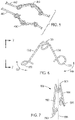
- FIG. 13 another exemplary embodiment of a tension regulator 810 is depicted.
- Tension regulator 810 is coupled to an actuation element 800, such as by joining a first end 812 and a second end 814 of tension regulator 810 to actuation element 800.
- Tension regulator 810 may be a band of elastic material, according to an exemplary embodiment.
- FIG. 13 depicts a state in which actuation element 800 is taut and lacks slack.
- tension regulator 810 is elastically deformed and stretched along actuation element 800, as shown in the exemplary embodiment of FIG. 13 .
- tension regulator 810 may relax along the directions indicated by arrows 820 in FIG. 14 to compensate for the slack and keep actuation element 800 taut. Similar to the exemplary embodiments of FIGS. 6-10 , tension regulator 810 may accommodate slack in actuation element 800 by diverting a path of actuation element 800 relative to an axis 830 that actuation element 800 extends along when actuation element 800 is taut and substantially straight, as depicted in FIG. 13 . For example, tension regulator 810 may increase a length of the path of actuation element 800 relative to axis 830.
- a tension regulator is may fastened to an actuation element so the tension regulator moves with the actuation element as the actuation element is paid out or wound upon an actuation input mechanism.
- contact surfaces of a tension regulator may be configured so that the tension regulator is fastened to the actuation element but if the tension regulator contacts a component of a force transmission mechanism (e.g., chassis portion 322 or actuation input mechanism 330, 332 in FIG. 3 ) as the actuation element is paid out or wound, the actuation element may be permitted to slide relative to the tension regulator to minimize or prevent damage to the tension regulator and force transmission mechanism components.
- surfaces of loops 551, 553, 555 of tension regulator 550 in the exemplary embodiment of FIG. 6 may be smooth to permit an actuation element to slide relative to tension regulator 550 when tension regulator 550 impacts a force transmission mechanism component.
- surfaces of tension regulators 600, 700, 800 of the exemplary embodiments of FIGS. 11-14 may also permit an actuation element to slide.
- surfaces of tension regulators may be shaped to minimize wear of an actuation element due to sliding against a tension regulator, such as by shaping tension regulator surfaces have large radii of curvature.
- tension regulator 900 includes surfaces that couple tension regulator 900 to an actuation element 910 but permit tension regulator 900 to slide relative to actuation element 910, such as when tension regulator 900 impacts a component of a force transmission mechanism.
- Tension regulator 900 may comprise a first leg 902 and a second leg 904 connected to a main pulley 903, with pulleys 901 and 905 disposed at ends of first and second legs 902, 904.
- First and second legs 902, 904 may bend (e.g., elastically deform) relative to main pulley 903, similar to the exemplary embodiments of FIGS. 6-11 .
- Actuation element 910 may be threaded through pulleys 901, 903, 905 so that tension regulator 900 is coupled to actuation element 910 but when tension regulator 900 impacts a force transmission mechanism component (e.g., chassis portion 322 or actuation input mechanism 330, 332 of FIG. 3 ), tension regulator 900 is permitted to slide relative to actuation element 910.
- tension regulator 900 may divert a path of actuation element 910 relative to an axis 920 of actuation element 910 (e.g., a path along which actuation element 910 extends when actuation element 910 is taut and substantially straight), similar to the exemplary embodiments of FIGS. 6-10 .
- tension regulator 900 may increase a path length of actuation element 910 relative to axis 920, according to an exemplary embodiment.
- a tension regulator may be coupled to a single actuation element.
- the tension regulators of the various exemplary embodiments described herein are not limited to being coupled to a single actuation element.
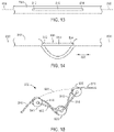
- FIG. 16 a tension regulator 1000 is shown coupled to a first actuation element 1010 and a second actuation element 1012.
- Actuation elements 1010, 1012 may be coupled to the same actuation input mechanism (e.g., actuation input mechanism 330 or 332 in the exemplary embodiment of FIG. 3 ).
- Tension regulator 1000 may comprise a first end 1002 coupled to actuation element 1012 and a second end 1004 coupled to actuation element 1010, with ends 1002, 1004 configured to slide relative to actuation elements 1010, 1012 as actuation elements 1010, 1012 are moved along the directions indicated by arrows 1020 in the exemplary embodiment of FIG. 16 .
- Tension regulator 1000 may comprise a deformable portion 1006 to facilitate deformation (e.g., elastic deformation) of tension regulator 1000 along the directions indicated by arrows 1022 in FIG. 16 , which facilitates compensation for slack in one or both of actuation elements 1010, 1012.
- Deformation portion 1006 may be, for example, a compliant portion of tension regulator 1000 that is more readily deformable that the remainder of tension regulator 1000, may be formed as a spring, or may have other configurations to facilitate elastic deformation of tension regulator 1000.
- actuation elements 1010, 1012 when actuation elements 1010, 1012 are taut and lack slack (e.g., prior to developing slack), actuation elements 1010, 1012 may extend along a path along axes 1030, 1032. In such a state, deformation portion 1006 is stretched (e.g., via elastic deformation) tension regulator 1000 experiences an increase in potential energy. As actuation elements 1010, 1012 develop slack, deformation portion 1006 may relax and tension regulator 1000 may divert actuation elements 1010, 1012 from a path along (e.g., substantially coaxial to) their respective axes 1030, 1032, similar to the exemplary embodiments of FIGS. 8-10 , to compensate for the slack. For example, portions of actuation elements 1010, 1012 extending through ends 1002, 1004 may form non-zero angles with the axes 1030, 1032.
- a tension regulator is coupled to an actuation element so that the tension regulator moves with the actuation element.
- the tension regulator moves relative to the chassis of a force transmission mechanism when the actuation element is paid out and wound upon an actuation input mechanism.
- the various exemplary embodiments described herein are not limited to such tension regulators and may also include tension regulators fixed to the chassis of a force transmission mechanism.
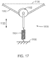
- tension regulator 1100 is shown that is fixed to a portion 1106 (e.g., chassis 320 in FIG. 3 ) of a force transmission mechanism.
- Tension regulator 1100 may be coupled to an actuation element 1110, such as by extending actuation element 1110 through a pulley 1102 or other member of tension regulator 1100 that couples tension regulator 1100 to actuation element 1110.
- Tension regulator 1100 may further comprise a deformable portion 1104 to facilitate deformation of tension regulator 1100 along the directions indicated by arrows 1120 in FIG. 17 , which facilitates compensation for slack in actuation element 1110.
- Deformation portion 1104 may be, for example, a compliant portion of tension regulator 1100 that is more readily deformable that the remainder of tension regulator 1100, may be formed as a spring, or may have other configurations to facilitate elastic deformation of tension regulator 1100.
- actuation element 1110 may follow a path along (e.g., substantially coaxial to) the axis 1130 of actuation element 1110, as discussed above with regard to the exemplary embodiments of FIGS. 8-10 .
- tension regulator 1100 may pull actuation element 1110, such as along a direction transverse (e.g., perpendicular to axis 1130).
- the path of actuation element 1110 differs from the path along axis 1130 when actuation element 1110 is taut and has not developed slack, similar to the exemplary embodiment of FIGS. 8-10 .
- tension regulator 1100 may increase a path length of actuation element 1110 as slack is developed in actuation element 1110.
- a tension regulator may have a single piece (e.g., monolithic) construction.
- a tension regulator having a single piece (e.g., monolithic) construction may be efficient to manufacture and couple to an actuation element but also effective for slack compensation.
- Tension regulator 550 may have a single piece (e.g., monolithic) construction.
- tension regulator 550 may be, for example, a single piece of wire.
- Tension regulator 600 of the exemplary embodiment of FIG. 11 may also have a single piece (e.g., monolithic) construction.
- tension regulator 600 may be a single piece of sheet metal having the shape shown in the exemplary embodiment of FIG. 11 .
- tension regulator 700 of FIG. 12 Another exemplary embodiment of a tension regulator that may have a single piece (e.g., monolithic) construction is tension regulator 700 of FIG. 12 .
- Tension regulator 700 may be molded as a single piece, for example.
- Tension regulator 810 of the exemplary embodiment of FIGS. 13 and 14 may also have a single piece (e.g., monolithic) construction.
- tension regulator 1000 of FIG. 16 may have a single piece (e.g., monolithic) construction that comprises ends 1002, 1004 and deformation portion 1006.
- tension regulators of the various exemplary embodiments contemplated herein have been described with reference to actuation elements within a force transmission mechanism of a surgical instrument, tension regulators of the various exemplary embodiments described herein are not limited to use with a force transmission mechanism of an instrument.
- tension regulators of the various exemplary embodiments described herein may be coupled to actuation elements of a patient side cart of teleoperated surgical system.
- tension regulators of the various exemplary embodiments described herein may be coupled to actuation elements (e.g., tension elements) used to actuate manipulator arms 110-113 of patient side cart 100 of the exemplary embodiment of FIG. 1 .
- tension regulators of the various exemplary embodiments described herein may be coupled to actuation elements within manipulator arms 110-113, not only to actuation elements located within force transmission mechanism 134 of FIG. 1 .
- the tension regulator may have a simple design that is efficient to manufacture and couple to an actuation element, while being capable of compensating for slack of the actuation element.
Claims (16)
- Vorrichtung zum Regulieren der Spannung eines Betätigungselements (242, 244, 340, 342, 344, 346, 440, 442, 560, 620, 800, 910, 1010, 1012, 1110) zur Betätigung der Bewegung eines chirurgischen Instruments (130, 200), wobei die Vorrichtung Folgendes umfasst:einen elastisch verformbaren Körper (350, 450, 550, 600, 700, 810, 900, 1000, 1100), der zum Koppeln mit dem Betätigungselement konfiguriert ist, so dass sich der elastisch verformbare Körper mit dem Betätigungselement bewegt;wobei der elastisch verformbare Körper zum elastischen Verformen als Reaktion auf einen in dem Betätigungselement auftretenden Durchhangzustand konfiguriert ist; undwobei der elastisch verformbare Körper bei Auftreten von Durchhang in dem Betätigungselement zum Ablenken eines Wegs des Betätigungselements konfiguriert ist, um den Durchhang aufzunehmen, wobei sich der Weg von einer Achse des Betätigungselements vor der Entwicklung von Durchhang in dem Betätigungselement unterscheidet.
- Vorrichtung nach Anspruch 1, wobei sich der elastisch verformbare Körper (350, 450, 550, 600, 700, 810, 900, 1000, 1100) über eine Länge des Wegs des Betätigungselements (242, 244, 340, 342, 344, 346, 440, 442, 560, 620, 800, 910, 1010, 1012, 1110) entlang einer Richtung erstreckt, die einen Winkel (575, 630) von ungleich Null mit der Achse des Betätigungselements vor der Entwicklung von Durchhang in dem Betätigungselement bildet.
- Vorrichtung nach Anspruch 1, wobei der elastisch verformbare Körper (350, 450, 550, 600, 700, 810, 900, 1000, 1100) bei Auftreten des Durchhangs das Betätigungselement (242, 244, 340, 342, 344, 346, 440, 442, 560, 620, 800, 910, 1010, 1012, 1110) entlang einer Richtung zieht, die im Wesentlichen quer zur Achse des Betätigungselements verläuft, bevor das Betätigungselement Durchhang entwickelt.
- Vorrichtung nach Anspruch 1, wobei der elastisch verformbare Körper (350, 450, 550, 600, 700, 810, 900, 1000, 1100) einen ersten und einen zweiten Schenkel (552, 554, 602, 604, 702, 704, 902, 904) umfasst, die mit einem zentralen Abschnitt des elastisch verformbaren Körpers verbunden sind, wobei der erste und der zweite Schenkel relativ zum zentralen Abschnitt elastisch verformbar sind.
- Vorrichtung nach Anspruch 4, wobei der zentrale Abschnitt des elastisch verformbaren Körpers (350, 450, 550, 600, 700, 810, 900, 1000, 1100) eine Schleife (551) umfasst, durch die sich das Betätigungselement (242, 244, 340, 342, 344, 346, 440, 442, 560, 620, 800, 910, 1010, 1012, 1110) erstreckt.
- Vorrichtung nach Anspruch 5, wobei der erste und der zweite Schenkel (552, 554, 602, 604, 702, 704, 902, 904) jeweils eine Schleife (553, 555) aufweisen, durch die sich das Betätigungselement (242, 244, 340, 342, 344, 346, 440, 442, 560, 620, 800, 910, 1010, 1012, 1110) erstreckt.
- Vorrichtung nach Anspruch 4, wobei ein spitzer Winkel zwischen dem ersten und dem zweiten Schenkel (552, 554, 602, 604, 702, 704, 902, 904) definiert ist, wenn der erste und der zweite Schenkel in einem nicht verformten Zustand sind.
- Vorrichtung nach Anspruch 4, wobei der elastisch verformbare Körper (350, 450, 550, 600, 700, 810, 900, 1000, 1100) aus einem einzelnen Stück Draht, einem einzelnen Stück Blech und einem einzelnen Formstück ausgewählt ist.
- Kraftübertragungsmechanismus (134, 210, 310) für ein ferngesteuertes chirurgisches Instrument (134, 200), der Folgendes umfasst:ein Chassis (211, 320, 322);einen an dem Chassis montierten Betätigungseingangsmechanismus (212, 214, 330, 332), wobei der Betätigungseingangsmechanismus zum Aufnehmen von Kräften von einer Betätigungsschnittstellenanordnung (122) eines ferngesteuerten chirurgischen Systems (100) konfiguriert ist;ein Betätigungselement (242, 244, 340, 342, 344, 346, 440, 442, 560, 620, 800, 910, 1010, 1012, 1110), das zum Übertragen einer Kraft konfiguriert ist, die ausreicht, um einen Endeffektor (220) des chirurgischen Instruments zu betätigen; undeinen Spannungsregler, der die Vorrichtung nach Anspruch 1 umfasst, gekoppelt mit dem Betätigungselement, um Durchhang des Betätigungselements zu kompensieren.
- Kraftübertragungsmechanismus (134, 210, 310) nach Anspruch 9, wobei sich der Spannungsregler mit dem Betätigungselement (242, 244, 340, 342, 344, 346, 440, 442, 560, 620, 800, 910, 1010, 1012, 1110) verschiebt, wenn das Betätigungselement auf den Betätigungseingangsmechanismus (212, 214, 330, 332) ausgegeben oder aufgewickelt wird.
- Kraftübertragungsmechanismus (134, 210, 310) nach Anspruch 9, wobei sich ein Teil des Betätigungselements (242, 244, 340, 342, 344, 346, 440, 442, 560, 620, 800, 910, 1010, 1012, 1110), der sich durch den Spannungsregler erstreckt, in einer kontinuierlichen Weise durch den Spannungsregler erstreckt.
- Kraftübertragungsmechanismus (134, 210, 310) nach Anspruch 9, wobei der Spannungsregler einen ersten und einen zweiten Schenkel (552, 554, 602, 604, 702, 704, 902, 904) umfasst, die mit einem zentralen Abschnitt des Spannungsreglers verbunden sind, und wobei der erste und der zweite Schenkel relativ zum zentralen Abschnitt elastisch verformbar sind.
- Kraftübertragungsmechanismus (134, 210, 310) nach Anspruch 9, wobei der Spannungsregler eine einteilige Konstruktion hat.
- Kraftübertragungsmechanismus (134, 210, 310) nach Anspruch 9, wobei das Betätigungselement (242, 244, 340, 342, 344, 346, 440, 442, 560, 620, 800, 910, 1010, 1012, 1110) zwei Betätigungselementabschnitte umfasst, die sich vom Betätigungseingangsmechanismus zu einer Ausgangsöffnung des Kraftübertragungsmechanismus erstrecken, und wobei der Spannungsregler mit einem der Betätigungselementabschnitte gekoppelt ist.
- Kraftübertragungsmechanismus (134, 210, 310) nach Anspruch 9, wobei das Betätigungselement (242, 244, 340, 342, 344, 346, 440, 442, 560, 620, 800, 910, 1010, 1012, 1110) zwei Betätigungselementabschnitte umfasst, die sich vom Betätigungseingangsmechanismus (212, 214, 330, 332) zu einer Ausgangsöffnung (324) des Kraftübertragungsmechanismus erstrecken, und wobei der Spannungsregler einen ersten Spannungsregler und einen zweiten Spannungsregler umfasst, wobei sowohl der erste Spannungsregler als auch der zweite Spannungsregler mit einem der beiden Betätigungselementabschnitte gekoppelt sind.
- Kraftübertragungsmechanismus (134, 210, 310) nach Anspruch 9, wobei das Betätigungselement (242, 244, 340, 342, 344, 346, 440, 442, 560, 620, 800, 910, 1010, 1012, 1110) zwei Betätigungselementabschnitte umfasst, die sich vom Betätigungseingangsmechanismus (212, 214, 330, 332) zu einer Ausgangsöffnung (324) des Kraftübertragungsmechanismus erstrecken, und wobei der Spannungsregler zwischen den Betätigungselementabschnitten gekoppelt ist.
Priority Applications (1)
| Application Number | Priority Date | Filing Date | Title |
|---|---|---|---|
| EP22157629.1A EP4018958A1 (de) | 2015-04-22 | 2016-04-21 | Spannungsregulator für betätigungselemente und zugehörige fernbetätigte instrumente, systeme und verfahren |
Applications Claiming Priority (2)
| Application Number | Priority Date | Filing Date | Title |
|---|---|---|---|
| US201562151138P | 2015-04-22 | 2015-04-22 | |
| PCT/US2016/028575 WO2016172299A1 (en) | 2015-04-22 | 2016-04-21 | Tension regulator for actuation elements, and related remotely actuated instruments, systems, and methods |
Related Child Applications (2)
| Application Number | Title | Priority Date | Filing Date |
|---|---|---|---|
| EP22157629.1A Division-Into EP4018958A1 (de) | 2015-04-22 | 2016-04-21 | Spannungsregulator für betätigungselemente und zugehörige fernbetätigte instrumente, systeme und verfahren |
| EP22157629.1A Division EP4018958A1 (de) | 2015-04-22 | 2016-04-21 | Spannungsregulator für betätigungselemente und zugehörige fernbetätigte instrumente, systeme und verfahren |
Publications (3)
| Publication Number | Publication Date |
|---|---|
| EP3285676A1 EP3285676A1 (de) | 2018-02-28 |
| EP3285676A4 EP3285676A4 (de) | 2018-12-19 |
| EP3285676B1 true EP3285676B1 (de) | 2022-07-27 |
Family
ID=57144304
Family Applications (2)
| Application Number | Title | Priority Date | Filing Date |
|---|---|---|---|
| EP16783826.7A Active EP3285676B1 (de) | 2015-04-22 | 2016-04-21 | Spannungsregulator für betätigungselemente und zugehörige fernbetätigte instrumente und systeme |
| EP22157629.1A Withdrawn EP4018958A1 (de) | 2015-04-22 | 2016-04-21 | Spannungsregulator für betätigungselemente und zugehörige fernbetätigte instrumente, systeme und verfahren |
Family Applications After (1)
| Application Number | Title | Priority Date | Filing Date |
|---|---|---|---|
| EP22157629.1A Withdrawn EP4018958A1 (de) | 2015-04-22 | 2016-04-21 | Spannungsregulator für betätigungselemente und zugehörige fernbetätigte instrumente, systeme und verfahren |
Country Status (5)
| Country | Link |
|---|---|
| US (2) | US11185380B2 (de) |
| EP (2) | EP3285676B1 (de) |
| KR (1) | KR102499214B1 (de) |
| CN (2) | CN107809981B (de) |
| WO (1) | WO2016172299A1 (de) |
Families Citing this family (16)
| Publication number | Priority date | Publication date | Assignee | Title |
|---|---|---|---|---|
| US10076348B2 (en) | 2013-08-15 | 2018-09-18 | Intuitive Surgical Operations, Inc. | Rotary input for lever actuation |
| US10550918B2 (en) | 2013-08-15 | 2020-02-04 | Intuitive Surgical Operations, Inc. | Lever actuated gimbal plate |
| US11007024B2 (en) | 2016-07-14 | 2021-05-18 | Intuitive Surgical Operations, Inc. | Geared grip actuation for medical instruments |
| CN109414300B (zh) | 2016-07-14 | 2021-11-09 | 直观外科手术操作公司 | 器械冲洗系统 |
| KR102543919B1 (ko) | 2016-07-14 | 2023-06-16 | 인튜어티브 서지컬 오퍼레이션즈 인코포레이티드 | 다중 케이블 의료 기기 |
| US20190231451A1 (en) | 2016-07-14 | 2019-08-01 | Intuitive Surgical Operations, Inc. | Geared roll drive for medical instrument |
| US11234784B2 (en) | 2016-09-22 | 2022-02-01 | Intuitive Surgical Operations, Inc. | Tension regulation of remotely actuated instruments, and related devices, systems, and methods |
| EP3541315A4 (de) * | 2016-11-21 | 2020-07-01 | Intuitive Surgical Operations Inc. | Kabellängekonservierendes medizinisches instrument |
| US10357321B2 (en) | 2017-02-24 | 2019-07-23 | Intuitive Surgical Operations, Inc. | Splayed cable guide for a medical instrument |
| US11076926B2 (en) | 2017-03-21 | 2021-08-03 | Intuitive Surgical Operations, Inc. | Manual release for medical device drive system |
| US11497567B2 (en) | 2018-02-08 | 2022-11-15 | Intuitive Surgical Operations, Inc. | Jointed control platform |
| US11118661B2 (en) | 2018-02-12 | 2021-09-14 | Intuitive Surgical Operations, Inc. | Instrument transmission converting roll to linear actuation |
| US11364084B2 (en) | 2018-11-21 | 2022-06-21 | Biosense Webster (Israel) Ltd. | Contact force compensation in a robot manipulator |
| KR102472766B1 (ko) * | 2020-12-14 | 2022-12-01 | 주식회사 로엔서지컬 | 수술도구용 와이어 장력 조절 장치 |
| KR102555196B1 (ko) * | 2021-05-17 | 2023-07-14 | 주식회사 로엔서지컬 | 와이어 히스테리시스 보상 기능을 갖는 수술 도구 장치 및 그 제어방법 |
| CN117794480A (zh) * | 2021-08-17 | 2024-03-29 | 直观外科手术操作公司 | 手术器械缆索控制和传送结构 |
Citations (1)
| Publication number | Priority date | Publication date | Assignee | Title |
|---|---|---|---|---|
| JP2004176532A (ja) * | 2002-09-09 | 2004-06-24 | Kunikazu Dojo | チェーン弛み矯正装置 |
Family Cites Families (12)
| Publication number | Priority date | Publication date | Assignee | Title |
|---|---|---|---|---|
| JP2002200092A (ja) * | 2000-12-27 | 2002-07-16 | Mizuho Co Ltd | 手術器械操作における駆動ワイヤーの緩み補正機構 |
| US8021326B2 (en) * | 2004-03-05 | 2011-09-20 | Hansen Medical, Inc. | Instrument driver for robotic catheter system |
| US8945148B2 (en) * | 2007-06-13 | 2015-02-03 | Intuitive Surgical Operations, Inc. | Surgical system instrument manipulator |
| EP2349168B1 (de) * | 2008-10-10 | 2015-03-18 | Fundacion Fatronik | Universal-haptikantriebssystem |
| JP2010194102A (ja) * | 2009-02-25 | 2010-09-09 | Olympus Corp | 分離型内視鏡、および、分離型内視鏡の操作部 |
| US8545515B2 (en) | 2009-09-23 | 2013-10-01 | Intuitive Surgical Operations, Inc. | Curved cannula surgical system |
| KR20240024323A (ko) | 2012-06-01 | 2024-02-23 | 인튜어티브 서지컬 오퍼레이션즈 인코포레이티드 | 멀티포트 수술 로봇 시스템 구조 |
| EP2854691B1 (de) | 2012-06-01 | 2021-11-17 | Intuitive Surgical Operations, Inc. | Redundante achse und freiheitsgrad für hardware-beschränkten remotecenter-robotermanipulator |
| BR112014031843B1 (pt) * | 2012-06-19 | 2022-01-18 | Baylis Medical Company Inc | Sistema de controle para o controle bidirecional de um cateter orientável |
| EP2914197B1 (de) * | 2012-11-02 | 2020-12-09 | Intuitive Surgical Operations, Inc. | Selbstantagonistischer antrieb für medizinische instrumente |
| US9839481B2 (en) * | 2013-03-07 | 2017-12-12 | Intuitive Surgical Operations, Inc. | Hybrid manual and robotic interventional instruments and methods of use |
| JP6265853B2 (ja) * | 2014-07-10 | 2018-01-24 | オリンパス株式会社 | 医療用機器 |
-
2016
- 2016-04-21 CN CN201680036371.2A patent/CN107809981B/zh active Active
- 2016-04-21 US US15/568,356 patent/US11185380B2/en active Active
- 2016-04-21 CN CN202110324355.6A patent/CN113229940A/zh active Pending
- 2016-04-21 EP EP16783826.7A patent/EP3285676B1/de active Active
- 2016-04-21 KR KR1020177033603A patent/KR102499214B1/ko active IP Right Grant
- 2016-04-21 WO PCT/US2016/028575 patent/WO2016172299A1/en active Application Filing
- 2016-04-21 EP EP22157629.1A patent/EP4018958A1/de not_active Withdrawn
-
2021
- 2021-10-22 US US17/507,937 patent/US20220039893A1/en active Pending
Patent Citations (1)
| Publication number | Priority date | Publication date | Assignee | Title |
|---|---|---|---|---|
| JP2004176532A (ja) * | 2002-09-09 | 2004-06-24 | Kunikazu Dojo | チェーン弛み矯正装置 |
Also Published As
| Publication number | Publication date |
|---|---|
| KR102499214B1 (ko) | 2023-02-14 |
| CN113229940A (zh) | 2021-08-10 |
| US20180116743A1 (en) | 2018-05-03 |
| EP4018958A1 (de) | 2022-06-29 |
| CN107809981B (zh) | 2021-04-16 |
| CN107809981A (zh) | 2018-03-16 |
| US20220039893A1 (en) | 2022-02-10 |
| EP3285676A4 (de) | 2018-12-19 |
| EP3285676A1 (de) | 2018-02-28 |
| WO2016172299A1 (en) | 2016-10-27 |
| KR20170139606A (ko) | 2017-12-19 |
| US11185380B2 (en) | 2021-11-30 |
Similar Documents
| Publication | Publication Date | Title |
|---|---|---|
| EP3285676B1 (de) | Spannungsregulator für betätigungselemente und zugehörige fernbetätigte instrumente und systeme | |
| EP2675385B1 (de) | Gelenkverknüpfungsstrukturen mit präferenzneigung | |
| US11871914B2 (en) | Operating self-antagonistic drives of medical instruments | |
| US11523732B2 (en) | Surgical device actuated using asymmetric spring system | |
| US11241290B2 (en) | Cable length conserving medical instrument | |
| US8161838B2 (en) | Method and apparatus for reducing at least one friction force opposing an axial force exerted through an actuator element | |
| US20220378537A1 (en) | Joint structures and related devices and methods | |
| US11890073B2 (en) | Tension regulation of remotely actuated instruments, and related devices, systems, and methods |
Legal Events
| Date | Code | Title | Description |
|---|---|---|---|
| STAA | Information on the status of an ep patent application or granted ep patent |
Free format text: STATUS: THE INTERNATIONAL PUBLICATION HAS BEEN MADE |
|
| PUAI | Public reference made under article 153(3) epc to a published international application that has entered the european phase |
Free format text: ORIGINAL CODE: 0009012 |
|
| STAA | Information on the status of an ep patent application or granted ep patent |
Free format text: STATUS: REQUEST FOR EXAMINATION WAS MADE |
|
| 17P | Request for examination filed |
Effective date: 20171024 |
|
| AK | Designated contracting states |
Kind code of ref document: A1 Designated state(s): AL AT BE BG CH CY CZ DE DK EE ES FI FR GB GR HR HU IE IS IT LI LT LU LV MC MK MT NL NO PL PT RO RS SE SI SK SM TR |
|
| AX | Request for extension of the european patent |
Extension state: BA ME |
|
| DAV | Request for validation of the european patent (deleted) | ||
| DAX | Request for extension of the european patent (deleted) | ||
| A4 | Supplementary search report drawn up and despatched |
Effective date: 20181116 |
|
| RIC1 | Information provided on ipc code assigned before grant |
Ipc: A61B 34/35 20160101ALN20181112BHEP Ipc: F16G 11/12 20060101ALI20181112BHEP Ipc: B25J 9/10 20060101ALI20181112BHEP Ipc: A61B 34/00 20160101ALN20181112BHEP Ipc: A61B 34/30 20160101AFI20181112BHEP |
|
| GRAP | Despatch of communication of intention to grant a patent |
Free format text: ORIGINAL CODE: EPIDOSNIGR1 |
|
| STAA | Information on the status of an ep patent application or granted ep patent |
Free format text: STATUS: GRANT OF PATENT IS INTENDED |
|
| INTG | Intention to grant announced |
Effective date: 20210923 |
|
| GRAJ | Information related to disapproval of communication of intention to grant by the applicant or resumption of examination proceedings by the epo deleted |
Free format text: ORIGINAL CODE: EPIDOSDIGR1 |
|
| STAA | Information on the status of an ep patent application or granted ep patent |
Free format text: STATUS: REQUEST FOR EXAMINATION WAS MADE |
|
| GRAP | Despatch of communication of intention to grant a patent |
Free format text: ORIGINAL CODE: EPIDOSNIGR1 |
|
| STAA | Information on the status of an ep patent application or granted ep patent |
Free format text: STATUS: GRANT OF PATENT IS INTENDED |
|
| INTC | Intention to grant announced (deleted) | ||
| INTG | Intention to grant announced |
Effective date: 20220215 |
|
| GRAS | Grant fee paid |
Free format text: ORIGINAL CODE: EPIDOSNIGR3 |
|
| GRAA | (expected) grant |
Free format text: ORIGINAL CODE: 0009210 |
|
| STAA | Information on the status of an ep patent application or granted ep patent |
Free format text: STATUS: THE PATENT HAS BEEN GRANTED |
|
| AK | Designated contracting states |
Kind code of ref document: B1 Designated state(s): AL AT BE BG CH CY CZ DE DK EE ES FI FR GB GR HR HU IE IS IT LI LT LU LV MC MK MT NL NO PL PT RO RS SE SI SK SM TR |
|
| REG | Reference to a national code |
Ref country code: CH Ref legal event code: EP |
|
| REG | Reference to a national code |
Ref country code: AT Ref legal event code: REF Ref document number: 1506556 Country of ref document: AT Kind code of ref document: T Effective date: 20220815 |
|
| REG | Reference to a national code |
Ref country code: DE Ref legal event code: R096 Ref document number: 602016073810 Country of ref document: DE |
|
| REG | Reference to a national code |
Ref country code: IE Ref legal event code: FG4D |
|
| REG | Reference to a national code |
Ref country code: LT Ref legal event code: MG9D |
|
| REG | Reference to a national code |
Ref country code: NL Ref legal event code: MP Effective date: 20220727 |
|
| PG25 | Lapsed in a contracting state [announced via postgrant information from national office to epo] |
Ref country code: SE Free format text: LAPSE BECAUSE OF FAILURE TO SUBMIT A TRANSLATION OF THE DESCRIPTION OR TO PAY THE FEE WITHIN THE PRESCRIBED TIME-LIMIT Effective date: 20220727 Ref country code: RS Free format text: LAPSE BECAUSE OF FAILURE TO SUBMIT A TRANSLATION OF THE DESCRIPTION OR TO PAY THE FEE WITHIN THE PRESCRIBED TIME-LIMIT Effective date: 20220727 Ref country code: PT Free format text: LAPSE BECAUSE OF FAILURE TO SUBMIT A TRANSLATION OF THE DESCRIPTION OR TO PAY THE FEE WITHIN THE PRESCRIBED TIME-LIMIT Effective date: 20221128 Ref country code: NO Free format text: LAPSE BECAUSE OF FAILURE TO SUBMIT A TRANSLATION OF THE DESCRIPTION OR TO PAY THE FEE WITHIN THE PRESCRIBED TIME-LIMIT Effective date: 20221027 Ref country code: NL Free format text: LAPSE BECAUSE OF FAILURE TO SUBMIT A TRANSLATION OF THE DESCRIPTION OR TO PAY THE FEE WITHIN THE PRESCRIBED TIME-LIMIT Effective date: 20220727 Ref country code: LV Free format text: LAPSE BECAUSE OF FAILURE TO SUBMIT A TRANSLATION OF THE DESCRIPTION OR TO PAY THE FEE WITHIN THE PRESCRIBED TIME-LIMIT Effective date: 20220727 Ref country code: LT Free format text: LAPSE BECAUSE OF FAILURE TO SUBMIT A TRANSLATION OF THE DESCRIPTION OR TO PAY THE FEE WITHIN THE PRESCRIBED TIME-LIMIT Effective date: 20220727 Ref country code: FI Free format text: LAPSE BECAUSE OF FAILURE TO SUBMIT A TRANSLATION OF THE DESCRIPTION OR TO PAY THE FEE WITHIN THE PRESCRIBED TIME-LIMIT Effective date: 20220727 Ref country code: ES Free format text: LAPSE BECAUSE OF FAILURE TO SUBMIT A TRANSLATION OF THE DESCRIPTION OR TO PAY THE FEE WITHIN THE PRESCRIBED TIME-LIMIT Effective date: 20220727 |
|
| REG | Reference to a national code |
Ref country code: AT Ref legal event code: MK05 Ref document number: 1506556 Country of ref document: AT Kind code of ref document: T Effective date: 20220727 |
|
| PG25 | Lapsed in a contracting state [announced via postgrant information from national office to epo] |
Ref country code: PL Free format text: LAPSE BECAUSE OF FAILURE TO SUBMIT A TRANSLATION OF THE DESCRIPTION OR TO PAY THE FEE WITHIN THE PRESCRIBED TIME-LIMIT Effective date: 20220727 Ref country code: IS Free format text: LAPSE BECAUSE OF FAILURE TO SUBMIT A TRANSLATION OF THE DESCRIPTION OR TO PAY THE FEE WITHIN THE PRESCRIBED TIME-LIMIT Effective date: 20221127 Ref country code: HR Free format text: LAPSE BECAUSE OF FAILURE TO SUBMIT A TRANSLATION OF THE DESCRIPTION OR TO PAY THE FEE WITHIN THE PRESCRIBED TIME-LIMIT Effective date: 20220727 Ref country code: GR Free format text: LAPSE BECAUSE OF FAILURE TO SUBMIT A TRANSLATION OF THE DESCRIPTION OR TO PAY THE FEE WITHIN THE PRESCRIBED TIME-LIMIT Effective date: 20221028 |
|
| PG25 | Lapsed in a contracting state [announced via postgrant information from national office to epo] |
Ref country code: SM Free format text: LAPSE BECAUSE OF FAILURE TO SUBMIT A TRANSLATION OF THE DESCRIPTION OR TO PAY THE FEE WITHIN THE PRESCRIBED TIME-LIMIT Effective date: 20220727 Ref country code: RO Free format text: LAPSE BECAUSE OF FAILURE TO SUBMIT A TRANSLATION OF THE DESCRIPTION OR TO PAY THE FEE WITHIN THE PRESCRIBED TIME-LIMIT Effective date: 20220727 Ref country code: DK Free format text: LAPSE BECAUSE OF FAILURE TO SUBMIT A TRANSLATION OF THE DESCRIPTION OR TO PAY THE FEE WITHIN THE PRESCRIBED TIME-LIMIT Effective date: 20220727 Ref country code: CZ Free format text: LAPSE BECAUSE OF FAILURE TO SUBMIT A TRANSLATION OF THE DESCRIPTION OR TO PAY THE FEE WITHIN THE PRESCRIBED TIME-LIMIT Effective date: 20220727 Ref country code: AT Free format text: LAPSE BECAUSE OF FAILURE TO SUBMIT A TRANSLATION OF THE DESCRIPTION OR TO PAY THE FEE WITHIN THE PRESCRIBED TIME-LIMIT Effective date: 20220727 |
|
| REG | Reference to a national code |
Ref country code: DE Ref legal event code: R097 Ref document number: 602016073810 Country of ref document: DE |
|
| PG25 | Lapsed in a contracting state [announced via postgrant information from national office to epo] |
Ref country code: SK Free format text: LAPSE BECAUSE OF FAILURE TO SUBMIT A TRANSLATION OF THE DESCRIPTION OR TO PAY THE FEE WITHIN THE PRESCRIBED TIME-LIMIT Effective date: 20220727 Ref country code: EE Free format text: LAPSE BECAUSE OF FAILURE TO SUBMIT A TRANSLATION OF THE DESCRIPTION OR TO PAY THE FEE WITHIN THE PRESCRIBED TIME-LIMIT Effective date: 20220727 |
|
| PLBE | No opposition filed within time limit |
Free format text: ORIGINAL CODE: 0009261 |
|
| STAA | Information on the status of an ep patent application or granted ep patent |
Free format text: STATUS: NO OPPOSITION FILED WITHIN TIME LIMIT |
|
| P01 | Opt-out of the competence of the unified patent court (upc) registered |
Effective date: 20230510 |
|
| PG25 | Lapsed in a contracting state [announced via postgrant information from national office to epo] |
Ref country code: AL Free format text: LAPSE BECAUSE OF FAILURE TO SUBMIT A TRANSLATION OF THE DESCRIPTION OR TO PAY THE FEE WITHIN THE PRESCRIBED TIME-LIMIT Effective date: 20220727 |
|
| 26N | No opposition filed |
Effective date: 20230502 |
|
| PGFP | Annual fee paid to national office [announced via postgrant information from national office to epo] |
Ref country code: DE Payment date: 20230427 Year of fee payment: 8 |
|
| PG25 | Lapsed in a contracting state [announced via postgrant information from national office to epo] |
Ref country code: SI Free format text: LAPSE BECAUSE OF FAILURE TO SUBMIT A TRANSLATION OF THE DESCRIPTION OR TO PAY THE FEE WITHIN THE PRESCRIBED TIME-LIMIT Effective date: 20220727 |
|
| REG | Reference to a national code |
Ref country code: CH Ref legal event code: PL |
|
| GBPC | Gb: european patent ceased through non-payment of renewal fee |
Effective date: 20230421 |
|
| PG25 | Lapsed in a contracting state [announced via postgrant information from national office to epo] |
Ref country code: LU Free format text: LAPSE BECAUSE OF NON-PAYMENT OF DUE FEES Effective date: 20230421 |
|
| REG | Reference to a national code |
Ref country code: BE Ref legal event code: MM Effective date: 20230430 |
|
| PG25 | Lapsed in a contracting state [announced via postgrant information from national office to epo] |
Ref country code: MC Free format text: LAPSE BECAUSE OF FAILURE TO SUBMIT A TRANSLATION OF THE DESCRIPTION OR TO PAY THE FEE WITHIN THE PRESCRIBED TIME-LIMIT Effective date: 20220727 |
|
| PG25 | Lapsed in a contracting state [announced via postgrant information from national office to epo] |
Ref country code: GB Free format text: LAPSE BECAUSE OF NON-PAYMENT OF DUE FEES Effective date: 20230421 |
|
| PG25 | Lapsed in a contracting state [announced via postgrant information from national office to epo] |
Ref country code: MC Free format text: LAPSE BECAUSE OF FAILURE TO SUBMIT A TRANSLATION OF THE DESCRIPTION OR TO PAY THE FEE WITHIN THE PRESCRIBED TIME-LIMIT Effective date: 20220727 Ref country code: LI Free format text: LAPSE BECAUSE OF NON-PAYMENT OF DUE FEES Effective date: 20230430 Ref country code: GB Free format text: LAPSE BECAUSE OF NON-PAYMENT OF DUE FEES Effective date: 20230421 Ref country code: FR Free format text: LAPSE BECAUSE OF NON-PAYMENT OF DUE FEES Effective date: 20230430 Ref country code: CH Free format text: LAPSE BECAUSE OF NON-PAYMENT OF DUE FEES Effective date: 20230430 |
|
| REG | Reference to a national code |
Ref country code: IE Ref legal event code: MM4A |
|
| PG25 | Lapsed in a contracting state [announced via postgrant information from national office to epo] |
Ref country code: BE Free format text: LAPSE BECAUSE OF NON-PAYMENT OF DUE FEES Effective date: 20230430 |
|
| PG25 | Lapsed in a contracting state [announced via postgrant information from national office to epo] |
Ref country code: IE Free format text: LAPSE BECAUSE OF NON-PAYMENT OF DUE FEES Effective date: 20230421 |
|
| PG25 | Lapsed in a contracting state [announced via postgrant information from national office to epo] |
Ref country code: IE Free format text: LAPSE BECAUSE OF NON-PAYMENT OF DUE FEES Effective date: 20230421 |