EP3285669B1 - Systèmes, dispositifs et procédés de fixation osseuse - Google Patents
Systèmes, dispositifs et procédés de fixation osseuse Download PDFInfo
- Publication number
- EP3285669B1 EP3285669B1 EP16719734.2A EP16719734A EP3285669B1 EP 3285669 B1 EP3285669 B1 EP 3285669B1 EP 16719734 A EP16719734 A EP 16719734A EP 3285669 B1 EP3285669 B1 EP 3285669B1
- Authority
- EP
- European Patent Office
- Prior art keywords
- bone
- shaft
- head
- implant
- threaded
- Prior art date
- Legal status (The legal status is an assumption and is not a legal conclusion. Google has not performed a legal analysis and makes no representation as to the accuracy of the status listed.)
- Active
Links
- 210000000988 bone and bone Anatomy 0.000 title claims description 61
- 238000000034 method Methods 0.000 title claims description 28
- 239000007943 implant Substances 0.000 claims description 22
- 229910045601 alloy Inorganic materials 0.000 claims description 11
- 239000000956 alloy Substances 0.000 claims description 11
- 238000004519 manufacturing process Methods 0.000 claims description 5
- 230000032683 aging Effects 0.000 claims description 4
- 238000000137 annealing Methods 0.000 claims description 4
- 238000003754 machining Methods 0.000 claims description 3
- 238000010791 quenching Methods 0.000 claims description 3
- 230000000171 quenching effect Effects 0.000 claims description 3
- 238000003483 aging Methods 0.000 claims description 2
- 238000005520 cutting process Methods 0.000 description 9
- 238000005553 drilling Methods 0.000 description 7
- 229910001069 Ti alloy Inorganic materials 0.000 description 6
- 239000000463 material Substances 0.000 description 5
- RTAQQCXQSZGOHL-UHFFFAOYSA-N Titanium Chemical compound [Ti] RTAQQCXQSZGOHL-UHFFFAOYSA-N 0.000 description 4
- 229910052719 titanium Inorganic materials 0.000 description 4
- 239000010936 titanium Substances 0.000 description 4
- ZPZCREMGFMRIRR-UHFFFAOYSA-N molybdenum titanium Chemical compound [Ti].[Mo] ZPZCREMGFMRIRR-UHFFFAOYSA-N 0.000 description 3
- 206010009245 Clavicle fracture Diseases 0.000 description 2
- 229910001182 Mo alloy Inorganic materials 0.000 description 2
- 210000001367 artery Anatomy 0.000 description 2
- 230000001054 cortical effect Effects 0.000 description 2
- 210000005036 nerve Anatomy 0.000 description 2
- 230000000149 penetrating effect Effects 0.000 description 2
- 210000003462 vein Anatomy 0.000 description 2
- 229910001040 Beta-titanium Inorganic materials 0.000 description 1
- 206010017076 Fracture Diseases 0.000 description 1
- 208000027418 Wounds and injury Diseases 0.000 description 1
- 230000001154 acute effect Effects 0.000 description 1
- 210000003109 clavicle Anatomy 0.000 description 1
- 230000007797 corrosion Effects 0.000 description 1
- 238000005260 corrosion Methods 0.000 description 1
- 230000006378 damage Effects 0.000 description 1
- 208000014674 injury Diseases 0.000 description 1
- 230000000630 rising effect Effects 0.000 description 1
- 238000010079 rubber tapping Methods 0.000 description 1
Images


Classifications
-
- A—HUMAN NECESSITIES
- A61—MEDICAL OR VETERINARY SCIENCE; HYGIENE
- A61B—DIAGNOSIS; SURGERY; IDENTIFICATION
- A61B17/00—Surgical instruments, devices or methods, e.g. tourniquets
- A61B17/56—Surgical instruments or methods for treatment of bones or joints; Devices specially adapted therefor
- A61B17/58—Surgical instruments or methods for treatment of bones or joints; Devices specially adapted therefor for osteosynthesis, e.g. bone plates, screws, setting implements or the like
- A61B17/68—Internal fixation devices, including fasteners and spinal fixators, even if a part thereof projects from the skin
- A61B17/80—Cortical plates, i.e. bone plates; Instruments for holding or positioning cortical plates, or for compressing bones attached to cortical plates
- A61B17/8052—Cortical plates, i.e. bone plates; Instruments for holding or positioning cortical plates, or for compressing bones attached to cortical plates immobilised relative to screws by interlocking form of the heads and plate holes, e.g. conical or threaded
- A61B17/8057—Cortical plates, i.e. bone plates; Instruments for holding or positioning cortical plates, or for compressing bones attached to cortical plates immobilised relative to screws by interlocking form of the heads and plate holes, e.g. conical or threaded the interlocking form comprising a thread
-
- A—HUMAN NECESSITIES
- A61—MEDICAL OR VETERINARY SCIENCE; HYGIENE
- A61B—DIAGNOSIS; SURGERY; IDENTIFICATION
- A61B17/00—Surgical instruments, devices or methods, e.g. tourniquets
- A61B17/56—Surgical instruments or methods for treatment of bones or joints; Devices specially adapted therefor
- A61B17/58—Surgical instruments or methods for treatment of bones or joints; Devices specially adapted therefor for osteosynthesis, e.g. bone plates, screws, setting implements or the like
- A61B17/68—Internal fixation devices, including fasteners and spinal fixators, even if a part thereof projects from the skin
- A61B17/84—Fasteners therefor or fasteners being internal fixation devices
- A61B17/86—Pins or screws or threaded wires; nuts therefor
- A61B17/8605—Heads, i.e. proximal ends projecting from bone
-
- A—HUMAN NECESSITIES
- A61—MEDICAL OR VETERINARY SCIENCE; HYGIENE
- A61B—DIAGNOSIS; SURGERY; IDENTIFICATION
- A61B17/00—Surgical instruments, devices or methods, e.g. tourniquets
- A61B17/56—Surgical instruments or methods for treatment of bones or joints; Devices specially adapted therefor
- A61B17/58—Surgical instruments or methods for treatment of bones or joints; Devices specially adapted therefor for osteosynthesis, e.g. bone plates, screws, setting implements or the like
- A61B17/68—Internal fixation devices, including fasteners and spinal fixators, even if a part thereof projects from the skin
- A61B17/84—Fasteners therefor or fasteners being internal fixation devices
- A61B17/86—Pins or screws or threaded wires; nuts therefor
- A61B17/8625—Shanks, i.e. parts contacting bone tissue
-
- A—HUMAN NECESSITIES
- A61—MEDICAL OR VETERINARY SCIENCE; HYGIENE
- A61B—DIAGNOSIS; SURGERY; IDENTIFICATION
- A61B17/00—Surgical instruments, devices or methods, e.g. tourniquets
- A61B17/56—Surgical instruments or methods for treatment of bones or joints; Devices specially adapted therefor
- A61B17/58—Surgical instruments or methods for treatment of bones or joints; Devices specially adapted therefor for osteosynthesis, e.g. bone plates, screws, setting implements or the like
- A61B17/68—Internal fixation devices, including fasteners and spinal fixators, even if a part thereof projects from the skin
- A61B17/84—Fasteners therefor or fasteners being internal fixation devices
- A61B17/86—Pins or screws or threaded wires; nuts therefor
- A61B17/866—Material or manufacture
-
- A—HUMAN NECESSITIES
- A61—MEDICAL OR VETERINARY SCIENCE; HYGIENE
- A61L—METHODS OR APPARATUS FOR STERILISING MATERIALS OR OBJECTS IN GENERAL; DISINFECTION, STERILISATION OR DEODORISATION OF AIR; CHEMICAL ASPECTS OF BANDAGES, DRESSINGS, ABSORBENT PADS OR SURGICAL ARTICLES; MATERIALS FOR BANDAGES, DRESSINGS, ABSORBENT PADS OR SURGICAL ARTICLES
- A61L27/00—Materials for grafts or prostheses or for coating grafts or prostheses
- A61L27/02—Inorganic materials
- A61L27/04—Metals or alloys
- A61L27/06—Titanium or titanium alloys
-
- A—HUMAN NECESSITIES
- A61—MEDICAL OR VETERINARY SCIENCE; HYGIENE
- A61L—METHODS OR APPARATUS FOR STERILISING MATERIALS OR OBJECTS IN GENERAL; DISINFECTION, STERILISATION OR DEODORISATION OF AIR; CHEMICAL ASPECTS OF BANDAGES, DRESSINGS, ABSORBENT PADS OR SURGICAL ARTICLES; MATERIALS FOR BANDAGES, DRESSINGS, ABSORBENT PADS OR SURGICAL ARTICLES
- A61L31/00—Materials for other surgical articles, e.g. stents, stent-grafts, shunts, surgical drapes, guide wires, materials for adhesion prevention, occluding devices, surgical gloves, tissue fixation devices
- A61L31/02—Inorganic materials
- A61L31/022—Metals or alloys
-
- C—CHEMISTRY; METALLURGY
- C22—METALLURGY; FERROUS OR NON-FERROUS ALLOYS; TREATMENT OF ALLOYS OR NON-FERROUS METALS
- C22C—ALLOYS
- C22C14/00—Alloys based on titanium
-
- C—CHEMISTRY; METALLURGY
- C22—METALLURGY; FERROUS OR NON-FERROUS ALLOYS; TREATMENT OF ALLOYS OR NON-FERROUS METALS
- C22F—CHANGING THE PHYSICAL STRUCTURE OF NON-FERROUS METALS AND NON-FERROUS ALLOYS
- C22F1/00—Changing the physical structure of non-ferrous metals or alloys by heat treatment or by hot or cold working
- C22F1/002—Changing the physical structure of non-ferrous metals or alloys by heat treatment or by hot or cold working by rapid cooling or quenching; cooling agents used therefor
-
- C—CHEMISTRY; METALLURGY
- C22—METALLURGY; FERROUS OR NON-FERROUS ALLOYS; TREATMENT OF ALLOYS OR NON-FERROUS METALS
- C22F—CHANGING THE PHYSICAL STRUCTURE OF NON-FERROUS METALS AND NON-FERROUS ALLOYS
- C22F1/00—Changing the physical structure of non-ferrous metals or alloys by heat treatment or by hot or cold working
- C22F1/16—Changing the physical structure of non-ferrous metals or alloys by heat treatment or by hot or cold working of other metals or alloys based thereon
- C22F1/18—High-melting or refractory metals or alloys based thereon
- C22F1/183—High-melting or refractory metals or alloys based thereon of titanium or alloys based thereon
-
- A—HUMAN NECESSITIES
- A61—MEDICAL OR VETERINARY SCIENCE; HYGIENE
- A61B—DIAGNOSIS; SURGERY; IDENTIFICATION
- A61B17/00—Surgical instruments, devices or methods, e.g. tourniquets
- A61B2017/00526—Methods of manufacturing
Definitions
- the present disclosure relates to a variable angle titanium-molybdenum alloy bone fastener, and associated bone fixation systems and methods.
- the present inventors have recognized that reducing the number of types of screws corresponding to a bone fixation system can reduce the inventory of bone fasteners required for a fixation procedure and enable provision of such systems in a single, sterile package. Additionally or alternatively, the present inventors have recognized that providing locking screws made from a titanium alloy that have the requisite hardness can reduce or eliminate problems arising from material mismatch between the plate and screw in a bone fixation system.
- the present teachings provide a method for manufacturing a bone fastener comprising a head and a shaft extending from the distal end of the head, a distal portion of the shaft comprising a drill portion, the method comprising: machining a TiMo alloy having a first hardness value and a first % elongation to form the bone fastener; annealing, quenching, and ageing the bone fastener to have a second hardness value that is greater than the first hardness value and a second % elongation that is both less than the first % elongation and greater than about 3% elongation, wherein the implant is annealed at about 1172K (1650°F).
- a system comprising a bone plate and a plurality of variable angle screws.
- the bone plate can comprise titanium.
- the bone plate can have a threaded screw hole and a non-threaded screw hole.
- the threaded screw hole can comprise N internal threads extending along a length of the screw hole that defines a threaded screw hole axis.
- Each of the plurality of variable angle screws can comprise a threaded head having M threads extending along at least a portion of a length of threaded head and a shaft extending from a distal end of the threaded head.
- Each of the plurality of variable angle screws can comprise a titanium-molybdenum alloy (TiMo) treated to have a hardness of at least 35 HRC.
- TiMo titanium-molybdenum alloy
- the M threads of the threaded head of a first screw of the plurality of variable angle screws can cut into the N internal threads of the threaded screw hole at a selected angle relative to the threaded screw hole axis to secure the first screw to the bone plate in locking engagement.
- a second screw of the plurality of variable angle screws can threadedly engage the bone through the non-threaded screw hole to secure the bone and plate in compressive engagement.
- M does not equal N.
- a bone fastener comprising a head and a shaft extending from the distal end of the head.
- the head can comprise two threads extending along at least a portion of a length of the threaded head.
- the two threads have thread starts that can be spaced 180° about a proximal end of the head.
- At least a portion of at least one of a major diameter and a minor diameter of the threaded head is tapered from a proximal end to a distal end thereof.
- Each of the two threads can have a thread angle of at least 90°.
- the bone fastener can be formed from a TiMo alloy treated to have a hardness of at least 35 HRC.
- the distal portion of the shaft can also comprise a drill portion.
- the drill portion can include a blade comprising a cutting lip and a relief surface trailing from the cutting lip and having a trailing edge.
- the TiMo alloy can be Ti-15Mo.
- a method of engaging a bone fastener in bone comprising: drilling a pilot hole through the near cortex of a bone, penetrating the near cortex with a bone fastener via the pilot hole, wherein the bone fastener can be formed from a TiMo alloy treated to have a hardness of at least 35 HRC, and wherein the bone fastener can comprise: a head that can comprise two threads having thread starts that can be spaced 180° apart about a proximal end of the head, wherein at least a portion of at least one of a major diameter and a minor diameter of the threaded head can be tapered from a proximal end to a distal end thereof, wherein the thread angle of each of the two threads can be at least 90°; and a shaft extending from a distal end of the head, wherein the shaft can comprise a helical thread extending from a point proximate a distal end towards a proximal end of the shaft, wherein at least one of a
- the systems can comprise implants and fasteners that both comprise titanium and minimize or eliminate problems rising from material mismatch. Additionally or alternatively, the systems can comprise an implant and a single type of fastener that can be used both locking and non-locking engagement with the implant and also installed either parallel to or at an oblique angle to an axis of a selected screw hole in the plate.
- a system 100 can comprise a bone plate 200 and a plurality of variable angle screws 300.
- the bone plate can comprise titanium.
- the bone plate can further comprise a titanium alloy.
- the bone plate 200 can have a threaded screw hole 210 and a non-threaded screw hole 220.
- the threaded screw hole 210 can comprise N internal threads 212 extending along a length of the screw hole that defines a threaded screw hole axis 214.
- Each of the plurality of variable angle screws 300 can comprise a threaded head 310 and a shaft 320 extending from a distal end of the threaded head 310.
- the threaded head 310 can comprise M threads 312 extending along at least a portion of a length of the threaded head 310.
- N does not equal M.
- Each of the plurality of variable angle screws 300 can comprise a titanium alloy treated to have a hardness of at least 35 HRC.
- the titanium alloy can be a titanium-molybdenum (TiMo) alloy.
- the titanium alloy can be Ti-15Mo.
- a second screw 300b of the plurality of variable angle screws can threadedly engage the bone through the non-threaded screw hole 220 to secure the bone and plate 200 in compressive engagement. Accordingly, a plurality of variable angle screws 300 can be used in both locking and non-locking engagement and both parallel to and at an oblique angle to the screw hole axis.
- the "thread angle” is a feature of a thread defined by the angle between adjacent flanks (i.e., the thread surface extending between the crest and root) measured at a cross-section of the thread.
- the N internal threads 212 can have a thread angle that can be less than the thread angle of the M threads 312 of the threaded head 310.
- the N internal threads 212 can have a thread angle of about 60°.
- the M threads 312 can have a thread angle of greater than 60°.
- the M threads 312 can have a thread angle of from about 90° to about 110°.
- the M threads 312 can have a thread angle of about 100°.
- the M threads 312 of the threaded head 310 can comprise two threads having thread starts that can be spaced 180° about a proximal end of the threaded head 310.
- at least a portion of at least one of a major diameter 312 and a minor diameter 314 of the threaded head 310 can be tapered from a proximal end to the distal end.
- the major diameter 312 of the threaded head can circumscribe a sphere.
- at least one of a major diameter 213 and a minor diameter 214 of at least a distal portion of the threaded screw hole 210 can be tapered towards the distal end.
- at least one of the major diameter 213 and the minor diameter 214 of the threaded screw hole can circumscribe a frustocone.
- the M threads of the threaded head 310 of a first screw 300a of the plurality of variable angle screws can cut into the N helical internal threads 212 of the threaded screw hole 210 at a selected angle relative to the threaded screw hole axis 214 to secure the first screw 310a to the bone plate 200 in locking engagement.
- the selected angle can be from about 0° to about 30°. In another aspect, the selected angle can be from about 0° to about 20°.
- the shaft 320 of the variable angle screw 300 can be at least partially threaded.
- a shaft thread 322 can extend from a point proximate a distal end towards a proximal end of the shaft 320.
- the shaft thread 322 can have a pitch of from about .5mm to about 1.25mm.
- the shaft thread 322 can have a pitch of about 1mm.
- at least one of a major diameter 324 and a minor diameter 326 of at least a distal portion of the shaft can be tapered to a point on the distal end of the shaft.
- the shaft 320 of the variable angle screw 300 can be self-tapping.
- variable angle screw 300 can be self-drilling.
- the point 327 can have a point angle of from about 60° to about 120°. In another aspect, the point 327 can have a point angle of about 90°.
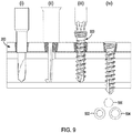
- the distal portion of the shaft 320 can further comprise a drill portion 328 including a blade 330 comprising a cutting lip 332 and a relief surface 334 trailing from the cutting lip and having a trailing edge 336. In one aspect, the cutting lip 332 and relief surface 334 can define an acute angle 338.
- the drill portion 328 can comprise two blades 330. In yet another aspect, the two blades can define a flute 340.
- the threaded head 310 can have a proximal end 342 that is transverse to a screw longitudinal axis defined by the shaft 320 and a driver aperture 344 defined in the proximal end.
- the driver aperture can be, for example and without limitation, a slot, a cruciform, a polygon, and the like.
- the driver aperture can be dimensioned to leave a selected minimum wall thickness 346 between the aperture and the edge of the threaded head to ensure that the maximum torque can be available for installing/removing the screw and that the threaded head 310 will not fail before the shaft 320.
- a screw having a 2.7mm cortical thread diameter and a 3.51mm head diameter can have a selected minimum wall thickness of about 0.24mm.
- a screw having a 3.5mm cortical thread diameter and a 4.49mm head diameter can have a selected minimum wall thickness of about 0.48mm.
- the system 100 further comprises a driver 400 having a distal end that mates with the driver aperture.
- the present teachings also provide for a method of manufacturing a bone fastener comprising: machining the TiMo alloy having a first hardness value and a first % elongation to form a bone fastener; heat treating, quenching, and ageing the bone fastener to have a second hardness value that can be greater than the first hardness value and a second % elongation that can be both less than the first % elongation and greater than about 3% elongation; the bone fastener is annealed at about 1172K (1650 °F).
- the TiMo alloy can be Ti-15Mo.
- heat treating the implant can comprise annealing the implant and, in a further aspect, solution annealing the implant.
- the implant can be aged from about 3 hours to about 20 hours. In one aspect, the implant can be aged for about 16 hours. In one aspect, the implant can be aged for about 4 hours. In another aspect, the implant can be aged at a temperature of from about 644K (700°F) to about 783K (950°F). In one aspect, the implant can be aged at a temperature of from about 722K (840°F) to about 755K (900°F).
- the first hardness value can be from about 35 to about 43 HRC. In another aspect, the second hardness value can be from about 43 to about 50 HRC. In one aspect, the second hardness value can be from about 44 to about 46 HRC. In another aspect, the second % elongation can be from about 4 to about 8.
- a method of engaging a bone fastener in bone comprising: (i) drilling a pilot hole through the near cortex of a bone, (ii) measuring the distance to the inner surface of the far cortex; (iii) penetrating the near cortex with a bone fastener via the pilot hole, wherein the bone fastener can be formed from a TiMo alloy treated to have a hardness of at least 35 HRC, and wherein the bone fastener can comprise: a head that can comprise two threads having thread starts that can be spaced 180° apart about a proximal end of the head, wherein at least a portion of at least one of a major diameter and a minor diameter of the threaded head can be tapered from a proximal end to a distal end thereof, wherein the thread angle of each of the two threads can be at least 90°; and a shaft extending from a distal end of the head, wherein the shaft can comprise
- the method for engaging a bone fastener in bone can further comprise a method for securing an implant.
- the implant can be a plate.
- the method can comprise a method for clavicle fracture fixation.
- clavicle fracture fixation bears a risk of injury and death due to risk associated with drilling through the far cortex of the clavicle due to the close proximity of important nerves, veins, and arteries.
- bone fasteners, and methods described herein eliminates the need for drilling through the far cortex and, even if the distal-most end of the bone fastener extends slightly past the far side of the far cortex, the risk of damaging any nerves 500, veins 502 and arteries 504 can be reduced or eliminated.
Landscapes
- Health & Medical Sciences (AREA)
- Chemical & Material Sciences (AREA)
- Orthopedic Medicine & Surgery (AREA)
- Life Sciences & Earth Sciences (AREA)
- Surgery (AREA)
- Engineering & Computer Science (AREA)
- General Health & Medical Sciences (AREA)
- Veterinary Medicine (AREA)
- Public Health (AREA)
- Animal Behavior & Ethology (AREA)
- Heart & Thoracic Surgery (AREA)
- Neurology (AREA)
- Nuclear Medicine, Radiotherapy & Molecular Imaging (AREA)
- Biomedical Technology (AREA)
- Medical Informatics (AREA)
- Molecular Biology (AREA)
- Organic Chemistry (AREA)
- Materials Engineering (AREA)
- Mechanical Engineering (AREA)
- Metallurgy (AREA)
- Thermal Sciences (AREA)
- Crystallography & Structural Chemistry (AREA)
- Physics & Mathematics (AREA)
- Epidemiology (AREA)
- Inorganic Chemistry (AREA)
- Vascular Medicine (AREA)
- Transplantation (AREA)
- Oral & Maxillofacial Surgery (AREA)
- Medicinal Chemistry (AREA)
- Dermatology (AREA)
- Surgical Instruments (AREA)
Claims (11)
- Procédé de fabrication d'une attache osseuse (300) comprenant une tête (310) et une tige (320) s'étendant depuis l'extrémité distale de la tête (310), une partie distale de la tige comprenant une partie foret (328), le procédé comprenant :l'usinage d'un alliage TiMo présentant une première valeur de dureté et un premier % d'allongement pour former l'attache osseuse ;le recuit, la trempe et le vieillissement de l'attache osseuse pour avoir une seconde valeur de dureté qui est supérieure à la première valeur de dureté et un second % d'allongement qui est à la fois inférieur au premier % d'allongement et supérieur à environ 3 % d'allongement, ledit implant étant recuit à environ 1172 K (1650°F).
- Procédé selon la revendication 1, ledit alliage TiMo étant le Ti-15Mo.
- Procédé selon l'une quelconque des revendications 1 à 2, ledit implant étant vieilli d'environ 3 heures à environ 20 heures.
- Procédé selon la revendication 3, ledit implant étant vieilli pendant environ 16 heures.
- Procédé selon la revendication 3, ledit implant étant vieilli pendant environ 4 heures.
- Procédé selon l'une quelconque des revendications 1 à 5, dans lequel l'implant est vieilli à une température d'environ 644 K à environ 783 K (environ 700°F à environ 950°F).
- Procédé selon la revendication 6, ledit implant étant vieilli à une température d'environ 722 K à environ 755 K (environ 840°F à environ 900°F).
- Procédé selon l'une quelconque des revendications 1 à 7, ladite première valeur de dureté étant d'environ 35 à environ 43 HRC.
- Procédé selon l'une quelconque des revendications 1 à 8, ladite seconde valeur de dureté étant d'environ 43 à environ 50 HRC.
- Procédé selon la revendication 9, ladite seconde valeur de dureté étant d'environ 44 à environ 46 HRC.
- Procédé selon l'une quelconque des revendications 1 à 10, ledit second % d'allongement étant d'environ 4 à environ 8.
Applications Claiming Priority (2)
| Application Number | Priority Date | Filing Date | Title |
|---|---|---|---|
| US201562152311P | 2015-04-24 | 2015-04-24 | |
| PCT/US2016/029006 WO2016172601A1 (fr) | 2015-04-24 | 2016-04-22 | Systèmes, dispositifs et procédés de fixation osseuse |
Publications (2)
| Publication Number | Publication Date |
|---|---|
| EP3285669A1 EP3285669A1 (fr) | 2018-02-28 |
| EP3285669B1 true EP3285669B1 (fr) | 2021-10-06 |
Family
ID=55861297
Family Applications (1)
| Application Number | Title | Priority Date | Filing Date |
|---|---|---|---|
| EP16719734.2A Active EP3285669B1 (fr) | 2015-04-24 | 2016-04-22 | Systèmes, dispositifs et procédés de fixation osseuse |
Country Status (3)
| Country | Link |
|---|---|
| US (2) | US10219847B2 (fr) |
| EP (1) | EP3285669B1 (fr) |
| WO (1) | WO2016172601A1 (fr) |
Families Citing this family (9)
| Publication number | Priority date | Publication date | Assignee | Title |
|---|---|---|---|---|
| WO2016172601A1 (fr) | 2015-04-24 | 2016-10-27 | Biomet Manufacturing, Llc | Systèmes, dispositifs et procédés de fixation osseuse |
| US20170065424A1 (en) * | 2015-09-04 | 2017-03-09 | Centric Medical, LLC | Small Bone Orthopedic Implants |
| US11389205B2 (en) | 2016-11-30 | 2022-07-19 | Stryker European Operations Holdings Llc | Spinal fastener with serrated thread |
| USD898196S1 (en) * | 2017-07-10 | 2020-10-06 | Stryker European Holdings I, Llc | Spinal fastener with serrated thread |
| USD857897S1 (en) * | 2018-03-21 | 2019-08-27 | Thomas Stuart Loftus | Bone screw |
| USD857898S1 (en) * | 2018-04-17 | 2019-08-27 | Thomas Stuart Loftus | Bone screw |
| US20210393303A1 (en) | 2018-11-13 | 2021-12-23 | Ortho Solutions Holdings Limited | Orthopedic implant system for variable angle locking having engineered mating thread engagement |
| US11957394B2 (en) | 2020-02-27 | 2024-04-16 | J.M. Longyear Manufacturing, Llc | Screw caddy |
| US11707307B2 (en) | 2020-12-04 | 2023-07-25 | Globus Medical, Inc. | Systems and methods for treating rib fractures and osteotomies using implantation |
Citations (1)
| Publication number | Priority date | Publication date | Assignee | Title |
|---|---|---|---|---|
| US20140005728A1 (en) * | 2012-06-27 | 2014-01-02 | Kenny Chi Beng Koay | Variable angle bone fixation device |
Family Cites Families (10)
| Publication number | Priority date | Publication date | Assignee | Title |
|---|---|---|---|---|
| US6783529B2 (en) | 1999-04-09 | 2004-08-31 | Depuy Orthopaedics, Inc. | Non-metal inserts for bone support assembly |
| ATE476148T1 (de) | 2003-06-12 | 2010-08-15 | Synthes Gmbh | Chirurgischer nagel |
| US7132103B2 (en) * | 2003-08-01 | 2006-11-07 | Enhan Technology Holdings International Co., Ltd. | Effects of sporoderm-broken germination activated ganoderma spores on treatment of spinal cord injury |
| US20050234561A1 (en) | 2004-04-20 | 2005-10-20 | Michael Nutt | Surface treatment for implants |
| US7837812B2 (en) | 2004-05-21 | 2010-11-23 | Ati Properties, Inc. | Metastable beta-titanium alloys and methods of processing the same by direct aging |
| CA2571508C (fr) | 2004-06-30 | 2012-03-13 | Synthes (U.S.A.) | Clou chirurgical |
| US20070233100A1 (en) | 2006-03-31 | 2007-10-04 | Metzinger Anthony J | Variable angle intramedullary nail |
| US10053758B2 (en) * | 2010-01-22 | 2018-08-21 | Ati Properties Llc | Production of high strength titanium |
| US9387022B2 (en) * | 2012-06-27 | 2016-07-12 | DePuy Synthes Products, Inc. | Variable angle bone fixation device |
| WO2016172601A1 (fr) | 2015-04-24 | 2016-10-27 | Biomet Manufacturing, Llc | Systèmes, dispositifs et procédés de fixation osseuse |
-
2016
- 2016-04-22 WO PCT/US2016/029006 patent/WO2016172601A1/fr unknown
- 2016-04-22 EP EP16719734.2A patent/EP3285669B1/fr active Active
- 2016-04-22 US US15/136,812 patent/US10219847B2/en active Active
-
2019
- 2019-01-23 US US16/255,244 patent/US10517659B2/en active Active
Patent Citations (1)
| Publication number | Priority date | Publication date | Assignee | Title |
|---|---|---|---|---|
| US20140005728A1 (en) * | 2012-06-27 | 2014-01-02 | Kenny Chi Beng Koay | Variable angle bone fixation device |
Also Published As
| Publication number | Publication date |
|---|---|
| US20160310182A1 (en) | 2016-10-27 |
| US10517659B2 (en) | 2019-12-31 |
| US20190150997A1 (en) | 2019-05-23 |
| WO2016172601A1 (fr) | 2016-10-27 |
| EP3285669A1 (fr) | 2018-02-28 |
| US10219847B2 (en) | 2019-03-05 |
Similar Documents
| Publication | Publication Date | Title |
|---|---|---|
| EP3285669B1 (fr) | Systèmes, dispositifs et procédés de fixation osseuse | |
| US10085782B2 (en) | Bone screw | |
| KR102121720B1 (ko) | 가변 각도 뼈 고정 장치 | |
| EP2373237B1 (fr) | Interface vis/plaque de verrouillage angulaire | |
| AU2013305674B2 (en) | Orthopedic fastener device | |
| US5899906A (en) | Threaded washer | |
| US9079263B2 (en) | Orthopedic fastener method | |
| JP2015027474A (ja) | 高度に多用途性のある角度可変の骨プレートシステム | |
| AU2021106958A4 (en) | A bone fixation system and a plate therefor | |
| AU2019467765B2 (en) | Variable angle locking construct for orthopedic applications | |
| CN210009110U (zh) | 一种带有钻头功能的金属骨针 | |
| RU210150U1 (ru) | Винт-спицефиксатор | |
| Jordan et al. | A review of the factors affecting the design, specification and material selection of screws for use in orthopaedic surgery |
Legal Events
| Date | Code | Title | Description |
|---|---|---|---|
| STAA | Information on the status of an ep patent application or granted ep patent |
Free format text: STATUS: THE INTERNATIONAL PUBLICATION HAS BEEN MADE |
|
| PUAI | Public reference made under article 153(3) epc to a published international application that has entered the european phase |
Free format text: ORIGINAL CODE: 0009012 |
|
| STAA | Information on the status of an ep patent application or granted ep patent |
Free format text: STATUS: REQUEST FOR EXAMINATION WAS MADE |
|
| 17P | Request for examination filed |
Effective date: 20171123 |
|
| AK | Designated contracting states |
Kind code of ref document: A1 Designated state(s): AL AT BE BG CH CY CZ DE DK EE ES FI FR GB GR HR HU IE IS IT LI LT LU LV MC MK MT NL NO PL PT RO RS SE SI SK SM TR |
|
| AX | Request for extension of the european patent |
Extension state: BA ME |
|
| DAV | Request for validation of the european patent (deleted) | ||
| DAX | Request for extension of the european patent (deleted) | ||
| STAA | Information on the status of an ep patent application or granted ep patent |
Free format text: STATUS: EXAMINATION IS IN PROGRESS |
|
| 17Q | First examination report despatched |
Effective date: 20191118 |
|
| STAA | Information on the status of an ep patent application or granted ep patent |
Free format text: STATUS: EXAMINATION IS IN PROGRESS |
|
| GRAP | Despatch of communication of intention to grant a patent |
Free format text: ORIGINAL CODE: EPIDOSNIGR1 |
|
| STAA | Information on the status of an ep patent application or granted ep patent |
Free format text: STATUS: GRANT OF PATENT IS INTENDED |
|
| INTG | Intention to grant announced |
Effective date: 20210415 |
|
| GRAS | Grant fee paid |
Free format text: ORIGINAL CODE: EPIDOSNIGR3 |
|
| GRAA | (expected) grant |
Free format text: ORIGINAL CODE: 0009210 |
|
| STAA | Information on the status of an ep patent application or granted ep patent |
Free format text: STATUS: THE PATENT HAS BEEN GRANTED |
|
| AK | Designated contracting states |
Kind code of ref document: B1 Designated state(s): AL AT BE BG CH CY CZ DE DK EE ES FI FR GB GR HR HU IE IS IT LI LT LU LV MC MK MT NL NO PL PT RO RS SE SI SK SM TR |
|
| REG | Reference to a national code |
Ref country code: GB Ref legal event code: FG4D |
|
| REG | Reference to a national code |
Ref country code: CH Ref legal event code: EP Ref country code: AT Ref legal event code: REF Ref document number: 1435561 Country of ref document: AT Kind code of ref document: T Effective date: 20211015 |
|
| REG | Reference to a national code |
Ref country code: IE Ref legal event code: FG4D |
|
| REG | Reference to a national code |
Ref country code: DE Ref legal event code: R096 Ref document number: 602016064591 Country of ref document: DE |
|
| REG | Reference to a national code |
Ref country code: LT Ref legal event code: MG9D |
|
| REG | Reference to a national code |
Ref country code: NL Ref legal event code: MP Effective date: 20211006 |
|
| REG | Reference to a national code |
Ref country code: AT Ref legal event code: MK05 Ref document number: 1435561 Country of ref document: AT Kind code of ref document: T Effective date: 20211006 |
|
| PG25 | Lapsed in a contracting state [announced via postgrant information from national office to epo] |
Ref country code: RS Free format text: LAPSE BECAUSE OF FAILURE TO SUBMIT A TRANSLATION OF THE DESCRIPTION OR TO PAY THE FEE WITHIN THE PRESCRIBED TIME-LIMIT Effective date: 20211006 Ref country code: LT Free format text: LAPSE BECAUSE OF FAILURE TO SUBMIT A TRANSLATION OF THE DESCRIPTION OR TO PAY THE FEE WITHIN THE PRESCRIBED TIME-LIMIT Effective date: 20211006 Ref country code: FI Free format text: LAPSE BECAUSE OF FAILURE TO SUBMIT A TRANSLATION OF THE DESCRIPTION OR TO PAY THE FEE WITHIN THE PRESCRIBED TIME-LIMIT Effective date: 20211006 Ref country code: BG Free format text: LAPSE BECAUSE OF FAILURE TO SUBMIT A TRANSLATION OF THE DESCRIPTION OR TO PAY THE FEE WITHIN THE PRESCRIBED TIME-LIMIT Effective date: 20220106 Ref country code: AT Free format text: LAPSE BECAUSE OF FAILURE TO SUBMIT A TRANSLATION OF THE DESCRIPTION OR TO PAY THE FEE WITHIN THE PRESCRIBED TIME-LIMIT Effective date: 20211006 |
|
| PG25 | Lapsed in a contracting state [announced via postgrant information from national office to epo] |
Ref country code: IS Free format text: LAPSE BECAUSE OF FAILURE TO SUBMIT A TRANSLATION OF THE DESCRIPTION OR TO PAY THE FEE WITHIN THE PRESCRIBED TIME-LIMIT Effective date: 20220206 Ref country code: SE Free format text: LAPSE BECAUSE OF FAILURE TO SUBMIT A TRANSLATION OF THE DESCRIPTION OR TO PAY THE FEE WITHIN THE PRESCRIBED TIME-LIMIT Effective date: 20211006 Ref country code: PT Free format text: LAPSE BECAUSE OF FAILURE TO SUBMIT A TRANSLATION OF THE DESCRIPTION OR TO PAY THE FEE WITHIN THE PRESCRIBED TIME-LIMIT Effective date: 20220207 Ref country code: PL Free format text: LAPSE BECAUSE OF FAILURE TO SUBMIT A TRANSLATION OF THE DESCRIPTION OR TO PAY THE FEE WITHIN THE PRESCRIBED TIME-LIMIT Effective date: 20211006 Ref country code: NO Free format text: LAPSE BECAUSE OF FAILURE TO SUBMIT A TRANSLATION OF THE DESCRIPTION OR TO PAY THE FEE WITHIN THE PRESCRIBED TIME-LIMIT Effective date: 20220106 Ref country code: NL Free format text: LAPSE BECAUSE OF FAILURE TO SUBMIT A TRANSLATION OF THE DESCRIPTION OR TO PAY THE FEE WITHIN THE PRESCRIBED TIME-LIMIT Effective date: 20211006 Ref country code: LV Free format text: LAPSE BECAUSE OF FAILURE TO SUBMIT A TRANSLATION OF THE DESCRIPTION OR TO PAY THE FEE WITHIN THE PRESCRIBED TIME-LIMIT Effective date: 20211006 Ref country code: HR Free format text: LAPSE BECAUSE OF FAILURE TO SUBMIT A TRANSLATION OF THE DESCRIPTION OR TO PAY THE FEE WITHIN THE PRESCRIBED TIME-LIMIT Effective date: 20211006 Ref country code: GR Free format text: LAPSE BECAUSE OF FAILURE TO SUBMIT A TRANSLATION OF THE DESCRIPTION OR TO PAY THE FEE WITHIN THE PRESCRIBED TIME-LIMIT Effective date: 20220107 Ref country code: ES Free format text: LAPSE BECAUSE OF FAILURE TO SUBMIT A TRANSLATION OF THE DESCRIPTION OR TO PAY THE FEE WITHIN THE PRESCRIBED TIME-LIMIT Effective date: 20211006 |
|
| REG | Reference to a national code |
Ref country code: DE Ref legal event code: R097 Ref document number: 602016064591 Country of ref document: DE |
|
| PG25 | Lapsed in a contracting state [announced via postgrant information from national office to epo] |
Ref country code: SM Free format text: LAPSE BECAUSE OF FAILURE TO SUBMIT A TRANSLATION OF THE DESCRIPTION OR TO PAY THE FEE WITHIN THE PRESCRIBED TIME-LIMIT Effective date: 20211006 Ref country code: SK Free format text: LAPSE BECAUSE OF FAILURE TO SUBMIT A TRANSLATION OF THE DESCRIPTION OR TO PAY THE FEE WITHIN THE PRESCRIBED TIME-LIMIT Effective date: 20211006 Ref country code: RO Free format text: LAPSE BECAUSE OF FAILURE TO SUBMIT A TRANSLATION OF THE DESCRIPTION OR TO PAY THE FEE WITHIN THE PRESCRIBED TIME-LIMIT Effective date: 20211006 Ref country code: EE Free format text: LAPSE BECAUSE OF FAILURE TO SUBMIT A TRANSLATION OF THE DESCRIPTION OR TO PAY THE FEE WITHIN THE PRESCRIBED TIME-LIMIT Effective date: 20211006 Ref country code: DK Free format text: LAPSE BECAUSE OF FAILURE TO SUBMIT A TRANSLATION OF THE DESCRIPTION OR TO PAY THE FEE WITHIN THE PRESCRIBED TIME-LIMIT Effective date: 20211006 Ref country code: CZ Free format text: LAPSE BECAUSE OF FAILURE TO SUBMIT A TRANSLATION OF THE DESCRIPTION OR TO PAY THE FEE WITHIN THE PRESCRIBED TIME-LIMIT Effective date: 20211006 |
|
| PLBE | No opposition filed within time limit |
Free format text: ORIGINAL CODE: 0009261 |
|
| STAA | Information on the status of an ep patent application or granted ep patent |
Free format text: STATUS: NO OPPOSITION FILED WITHIN TIME LIMIT |
|
| 26N | No opposition filed |
Effective date: 20220707 |
|
| PG25 | Lapsed in a contracting state [announced via postgrant information from national office to epo] |
Ref country code: AL Free format text: LAPSE BECAUSE OF FAILURE TO SUBMIT A TRANSLATION OF THE DESCRIPTION OR TO PAY THE FEE WITHIN THE PRESCRIBED TIME-LIMIT Effective date: 20211006 |
|
| PG25 | Lapsed in a contracting state [announced via postgrant information from national office to epo] |
Ref country code: SI Free format text: LAPSE BECAUSE OF FAILURE TO SUBMIT A TRANSLATION OF THE DESCRIPTION OR TO PAY THE FEE WITHIN THE PRESCRIBED TIME-LIMIT Effective date: 20211006 |
|
| REG | Reference to a national code |
Ref country code: BE Ref legal event code: MM Effective date: 20220430 |
|
| PG25 | Lapsed in a contracting state [announced via postgrant information from national office to epo] |
Ref country code: MC Free format text: LAPSE BECAUSE OF FAILURE TO SUBMIT A TRANSLATION OF THE DESCRIPTION OR TO PAY THE FEE WITHIN THE PRESCRIBED TIME-LIMIT Effective date: 20211006 Ref country code: LU Free format text: LAPSE BECAUSE OF NON-PAYMENT OF DUE FEES Effective date: 20220422 |
|
| PG25 | Lapsed in a contracting state [announced via postgrant information from national office to epo] |
Ref country code: BE Free format text: LAPSE BECAUSE OF NON-PAYMENT OF DUE FEES Effective date: 20220430 |
|
| PG25 | Lapsed in a contracting state [announced via postgrant information from national office to epo] |
Ref country code: IE Free format text: LAPSE BECAUSE OF NON-PAYMENT OF DUE FEES Effective date: 20220422 |
|
| PG25 | Lapsed in a contracting state [announced via postgrant information from national office to epo] |
Ref country code: IT Free format text: LAPSE BECAUSE OF FAILURE TO SUBMIT A TRANSLATION OF THE DESCRIPTION OR TO PAY THE FEE WITHIN THE PRESCRIBED TIME-LIMIT Effective date: 20211006 |
|
| P01 | Opt-out of the competence of the unified patent court (upc) registered |
Effective date: 20230619 |
|
| PG25 | Lapsed in a contracting state [announced via postgrant information from national office to epo] |
Ref country code: HU Free format text: LAPSE BECAUSE OF FAILURE TO SUBMIT A TRANSLATION OF THE DESCRIPTION OR TO PAY THE FEE WITHIN THE PRESCRIBED TIME-LIMIT; INVALID AB INITIO Effective date: 20160422 |
|
| PG25 | Lapsed in a contracting state [announced via postgrant information from national office to epo] |
Ref country code: MK Free format text: LAPSE BECAUSE OF FAILURE TO SUBMIT A TRANSLATION OF THE DESCRIPTION OR TO PAY THE FEE WITHIN THE PRESCRIBED TIME-LIMIT Effective date: 20211006 Ref country code: CY Free format text: LAPSE BECAUSE OF FAILURE TO SUBMIT A TRANSLATION OF THE DESCRIPTION OR TO PAY THE FEE WITHIN THE PRESCRIBED TIME-LIMIT Effective date: 20211006 |
|
| PG25 | Lapsed in a contracting state [announced via postgrant information from national office to epo] |
Ref country code: TR Free format text: LAPSE BECAUSE OF FAILURE TO SUBMIT A TRANSLATION OF THE DESCRIPTION OR TO PAY THE FEE WITHIN THE PRESCRIBED TIME-LIMIT Effective date: 20211006 |
|
| PGFP | Annual fee paid to national office [announced via postgrant information from national office to epo] |
Ref country code: GB Payment date: 20240408 Year of fee payment: 9 |
|
| PGFP | Annual fee paid to national office [announced via postgrant information from national office to epo] |
Ref country code: DE Payment date: 20240322 Year of fee payment: 9 |
|
| PGFP | Annual fee paid to national office [announced via postgrant information from national office to epo] |
Ref country code: CH Payment date: 20240501 Year of fee payment: 9 |
|
| PGFP | Annual fee paid to national office [announced via postgrant information from national office to epo] |
Ref country code: FR Payment date: 20240405 Year of fee payment: 9 |