EP3285545B1 - Dispositif de chauffage - Google Patents
Dispositif de chauffage Download PDFInfo
- Publication number
- EP3285545B1 EP3285545B1 EP16306064.3A EP16306064A EP3285545B1 EP 3285545 B1 EP3285545 B1 EP 3285545B1 EP 16306064 A EP16306064 A EP 16306064A EP 3285545 B1 EP3285545 B1 EP 3285545B1
- Authority
- EP
- European Patent Office
- Prior art keywords
- heating device
- electrically conductive
- legs
- component
- blade
- Prior art date
- Legal status (The legal status is an assumption and is not a legal conclusion. Google has not performed a legal analysis and makes no representation as to the accuracy of the status listed.)
- Active
Links
- 238000010438 heat treatment Methods 0.000 title claims description 83
- 239000004744 fabric Substances 0.000 claims description 35
- 239000000463 material Substances 0.000 claims description 6
- 239000002759 woven fabric Substances 0.000 claims description 5
- OKTJSMMVPCPJKN-UHFFFAOYSA-N Carbon Chemical compound [C] OKTJSMMVPCPJKN-UHFFFAOYSA-N 0.000 claims description 3
- 230000015572 biosynthetic process Effects 0.000 claims description 3
- 229910052799 carbon Inorganic materials 0.000 claims description 3
- 239000000835 fiber Substances 0.000 claims description 3
- 239000011888 foil Substances 0.000 description 6
- 238000004519 manufacturing process Methods 0.000 description 3
- 239000000853 adhesive Substances 0.000 description 2
- 230000001070 adhesive effect Effects 0.000 description 2
- 238000010586 diagram Methods 0.000 description 2
- 238000005516 engineering process Methods 0.000 description 2
- 230000003628 erosive effect Effects 0.000 description 2
- 239000003365 glass fiber Substances 0.000 description 2
- 239000011810 insulating material Substances 0.000 description 2
- 241000531908 Aramides Species 0.000 description 1
- 244000025254 Cannabis sativa Species 0.000 description 1
- 235000012766 Cannabis sativa ssp. sativa var. sativa Nutrition 0.000 description 1
- 235000012765 Cannabis sativa ssp. sativa var. spontanea Nutrition 0.000 description 1
- 241000208202 Linaceae Species 0.000 description 1
- 235000004431 Linum usitatissimum Nutrition 0.000 description 1
- 229920000914 Metallic fiber Polymers 0.000 description 1
- 239000004760 aramid Substances 0.000 description 1
- 229920003235 aromatic polyamide Polymers 0.000 description 1
- 235000009120 camo Nutrition 0.000 description 1
- 235000005607 chanvre indien Nutrition 0.000 description 1
- 239000011248 coating agent Substances 0.000 description 1
- 238000000576 coating method Methods 0.000 description 1
- 239000012141 concentrate Substances 0.000 description 1
- 239000004020 conductor Substances 0.000 description 1
- 230000007547 defect Effects 0.000 description 1
- 230000001627 detrimental effect Effects 0.000 description 1
- 239000012777 electrically insulating material Substances 0.000 description 1
- 231100001261 hazardous Toxicity 0.000 description 1
- 239000011487 hemp Substances 0.000 description 1
- 239000003973 paint Substances 0.000 description 1
Images
Classifications
-
- H—ELECTRICITY
- H05—ELECTRIC TECHNIQUES NOT OTHERWISE PROVIDED FOR
- H05B—ELECTRIC HEATING; ELECTRIC LIGHT SOURCES NOT OTHERWISE PROVIDED FOR; CIRCUIT ARRANGEMENTS FOR ELECTRIC LIGHT SOURCES, IN GENERAL
- H05B3/00—Ohmic-resistance heating
- H05B3/20—Heating elements having extended surface area substantially in a two-dimensional plane, e.g. plate-heater
- H05B3/34—Heating elements having extended surface area substantially in a two-dimensional plane, e.g. plate-heater flexible, e.g. heating nets or webs
- H05B3/342—Heating elements having extended surface area substantially in a two-dimensional plane, e.g. plate-heater flexible, e.g. heating nets or webs heaters used in textiles
- H05B3/347—Heating elements having extended surface area substantially in a two-dimensional plane, e.g. plate-heater flexible, e.g. heating nets or webs heaters used in textiles woven fabrics
-
- H—ELECTRICITY
- H05—ELECTRIC TECHNIQUES NOT OTHERWISE PROVIDED FOR
- H05B—ELECTRIC HEATING; ELECTRIC LIGHT SOURCES NOT OTHERWISE PROVIDED FOR; CIRCUIT ARRANGEMENTS FOR ELECTRIC LIGHT SOURCES, IN GENERAL
- H05B3/00—Ohmic-resistance heating
- H05B3/20—Heating elements having extended surface area substantially in a two-dimensional plane, e.g. plate-heater
- H05B3/34—Heating elements having extended surface area substantially in a two-dimensional plane, e.g. plate-heater flexible, e.g. heating nets or webs
- H05B3/342—Heating elements having extended surface area substantially in a two-dimensional plane, e.g. plate-heater flexible, e.g. heating nets or webs heaters used in textiles
-
- H—ELECTRICITY
- H05—ELECTRIC TECHNIQUES NOT OTHERWISE PROVIDED FOR
- H05B—ELECTRIC HEATING; ELECTRIC LIGHT SOURCES NOT OTHERWISE PROVIDED FOR; CIRCUIT ARRANGEMENTS FOR ELECTRIC LIGHT SOURCES, IN GENERAL
- H05B3/00—Ohmic-resistance heating
- H05B3/02—Details
- H05B3/03—Electrodes
-
- B—PERFORMING OPERATIONS; TRANSPORTING
- B64—AIRCRAFT; AVIATION; COSMONAUTICS
- B64D—EQUIPMENT FOR FITTING IN OR TO AIRCRAFT; FLIGHT SUITS; PARACHUTES; ARRANGEMENTS OR MOUNTING OF POWER PLANTS OR PROPULSION TRANSMISSIONS IN AIRCRAFT
- B64D15/00—De-icing or preventing icing on exterior surfaces of aircraft
- B64D15/12—De-icing or preventing icing on exterior surfaces of aircraft by electric heating
-
- F—MECHANICAL ENGINEERING; LIGHTING; HEATING; WEAPONS; BLASTING
- F01—MACHINES OR ENGINES IN GENERAL; ENGINE PLANTS IN GENERAL; STEAM ENGINES
- F01D—NON-POSITIVE DISPLACEMENT MACHINES OR ENGINES, e.g. STEAM TURBINES
- F01D25/00—Component parts, details, or accessories, not provided for in, or of interest apart from, other groups
- F01D25/02—De-icing means for engines having icing phenomena
-
- F—MECHANICAL ENGINEERING; LIGHTING; HEATING; WEAPONS; BLASTING
- F03—MACHINES OR ENGINES FOR LIQUIDS; WIND, SPRING, OR WEIGHT MOTORS; PRODUCING MECHANICAL POWER OR A REACTIVE PROPULSIVE THRUST, NOT OTHERWISE PROVIDED FOR
- F03D—WIND MOTORS
- F03D80/00—Details, components or accessories not provided for in groups F03D1/00 - F03D17/00
- F03D80/40—Ice detection; De-icing means
-
- F—MECHANICAL ENGINEERING; LIGHTING; HEATING; WEAPONS; BLASTING
- F05—INDEXING SCHEMES RELATING TO ENGINES OR PUMPS IN VARIOUS SUBCLASSES OF CLASSES F01-F04
- F05B—INDEXING SCHEME RELATING TO WIND, SPRING, WEIGHT, INERTIA OR LIKE MOTORS, TO MACHINES OR ENGINES FOR LIQUIDS COVERED BY SUBCLASSES F03B, F03D AND F03G
- F05B2240/00—Components
- F05B2240/20—Rotors
- F05B2240/21—Rotors for wind turbines
-
- F—MECHANICAL ENGINEERING; LIGHTING; HEATING; WEAPONS; BLASTING
- F05—INDEXING SCHEMES RELATING TO ENGINES OR PUMPS IN VARIOUS SUBCLASSES OF CLASSES F01-F04
- F05D—INDEXING SCHEME FOR ASPECTS RELATING TO NON-POSITIVE-DISPLACEMENT MACHINES OR ENGINES, GAS-TURBINES OR JET-PROPULSION PLANTS
- F05D2240/00—Components
- F05D2240/20—Rotors
- F05D2240/24—Rotors for turbines
-
- F—MECHANICAL ENGINEERING; LIGHTING; HEATING; WEAPONS; BLASTING
- F05—INDEXING SCHEMES RELATING TO ENGINES OR PUMPS IN VARIOUS SUBCLASSES OF CLASSES F01-F04
- F05D—INDEXING SCHEME FOR ASPECTS RELATING TO NON-POSITIVE-DISPLACEMENT MACHINES OR ENGINES, GAS-TURBINES OR JET-PROPULSION PLANTS
- F05D2240/00—Components
- F05D2240/20—Rotors
- F05D2240/30—Characteristics of rotor blades, i.e. of any element transforming dynamic fluid energy to or from rotational energy and being attached to a rotor
- F05D2240/303—Characteristics of rotor blades, i.e. of any element transforming dynamic fluid energy to or from rotational energy and being attached to a rotor related to the leading edge of a rotor blade
-
- H—ELECTRICITY
- H05—ELECTRIC TECHNIQUES NOT OTHERWISE PROVIDED FOR
- H05B—ELECTRIC HEATING; ELECTRIC LIGHT SOURCES NOT OTHERWISE PROVIDED FOR; CIRCUIT ARRANGEMENTS FOR ELECTRIC LIGHT SOURCES, IN GENERAL
- H05B2203/00—Aspects relating to Ohmic resistive heating covered by group H05B3/00
- H05B2203/014—Heaters using resistive wires or cables not provided for in H05B3/54
- H05B2203/015—Heater wherein the heating element is interwoven with the textile
-
- Y—GENERAL TAGGING OF NEW TECHNOLOGICAL DEVELOPMENTS; GENERAL TAGGING OF CROSS-SECTIONAL TECHNOLOGIES SPANNING OVER SEVERAL SECTIONS OF THE IPC; TECHNICAL SUBJECTS COVERED BY FORMER USPC CROSS-REFERENCE ART COLLECTIONS [XRACs] AND DIGESTS
- Y02—TECHNOLOGIES OR APPLICATIONS FOR MITIGATION OR ADAPTATION AGAINST CLIMATE CHANGE
- Y02E—REDUCTION OF GREENHOUSE GAS [GHG] EMISSIONS, RELATED TO ENERGY GENERATION, TRANSMISSION OR DISTRIBUTION
- Y02E10/00—Energy generation through renewable energy sources
- Y02E10/70—Wind energy
- Y02E10/72—Wind turbines with rotation axis in wind direction
Definitions
- the present disclosure relates to heating devices for preventing ice formation on components.
- ice can be a hazardous problem.
- Anti-icing or de-icing technologies may be fitted on aircraft to avoid ice accretion or remove ice.
- Existing technologies may be glued onto an aircraft frame and may be subject to erosion, foreign object damage and may interfere with the aerodynamic properties of the component.
- components may have complex surface geometry for mounting thereon.
- Electrical heating devices are generally made with metallic foil and have power cables at each end (for example root and tip) of the product. In case of impact through the device, the power cable can be cut and the whole heating device rendered out of service. Furthermore foil has low damage tolerance due to the width of the foil path itself. Foil heating devices may be difficult to manufacture as it can be difficult to deform the foil into the complex shapes required, often resulting in defects and high levels of rejected parts.
- a prior art heating device having the features of the preamble of claim 1 is disclosed in US 2006/027863 A1 .
- a further prior art heating device is disclosed in WO 2006/130454 A2 .
- this disclosure provides a heating device in accordance with claim 1.
- All electrical connections of the heating device may be positioned at the first end of the device.
- the legs may be substantially the same length and may be spaced from each other by a gap, the gap being sized to prevent electrical connection between the legs along the length of the legs.
- the gap has an equal width along the length of the legs.
- the electrically conductive fabric may be a woven fabric incorporating electrically conductive fibres therein.
- the electrically conductive fabric is made from a carbon fibre material.
- the conductive fabric may be formed from a single piece of conductive fabric
- a component may comprise a surface prone to ice formation and the heating device as described above mounted to the surface.
- the component may be an aeronautic or wind turbine product such as an aeroplane wing, propeller blade, wind turbine blade or fan blade.
- the component may be a blade having a root and a tip, the electrical connections of the heating device being positioned adjacent the root of the blade.
- the heating device may be mounted to a leading edge of the component.
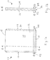
- the heating device 10 has a first end 15, a second, opposed end 18 and two side edges 17 and 19.
- the heating device 10 also includes a first ply 22 of electrically conductive fabric and a second ply 24 of electrically conductive fabric.
- the first ply 22 and the second ply 24 are joined at the second end 18 of the heating device 10, as best shown in Figure 1b .
- An electrically insulating layer for example an electrically insulating fabric 30, is positioned between the first ply 22 and the second ply 24 and extends beyond both plies 22, 24 to the first end 15 of the heating device 10.
- a first electrical connection or terminal 42 such as a power cable is connected to the first ply 22 along the first end 15 of the device 10.
- a second electrical connection or terminal 44, such as power cable is connected to the second ply 24 along the first end 15 of the device 10.
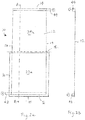
- the plies 22, 24 of the heating device 10 may be formed from a single sheet of electrically conductive, flexible fabric 12 as shown in Figures 2a and 2b .
- the sheet 12 is rectangular in the illustrated embodiment, although it will be appreciated that other shapes may be used for the sheet 12.
- Power terminals 42, 44 are attached at or adjacent first and second opposed ends 14, 16 of the sheet 12. In the embodiment, the first power terminal 42 is connected to the sheet 12 along the entire second end 16 and the second power terminal 44 is connected to the sheet 12 along the entire first end 14. Other positions of the power cables 42, 44 in the end regions will be appreciated, for example the terminals may be spaced slightly from the ends 14, 16 of the sheet 12 and/or may be attached to just a portion of the ends 14, 16.
- the sheet of electrically conductive fabric 12 includes a first part 22a which forms the first ply 22 and a second part 24a which forms the second ply 24.
- the electrically insulating fabric 30 is positioned over the first part 22a and the sheet 12 is folded about a fold line 18a such that the second part 24a is folded over onto the insulating fabric 30.
- the fold line 18a is between the power terminals 42, 44 and spaced therefrom. In the illustrated embodiment the fold line 18a is approximately half-way between the two power terminals 42, 44 and parallel thereto.
- the fold line 18 thus defines equal sized rectangular first and second parts 22a, 24a.
- the fold line 18a of the sheet 12 thereby forms the second end 18 of the heating device 10, as shown in Figures 1 a and 1 b.
- Both power terminals 42, 44 are positioned at or adjacent to the first end 15 of the heating device 10. Alternatively the fold line may be closer to one or other of the power terminals 42, 44 such that folding the sheet 12 results in the terminals 42, 44 being offset from each other in a region adjacent the second end 16.
- the electrically conductive fabrics forming the first and second plies 22, 24 are made from the same material, for example a woven carbon fibre material. It will be appreciated that other electrically conductive fabrics may be used such as other woven or non-woven materials, for example incorporating conductive fibres such as metallic fibres or glass fibres having a conductive sheath. In alternative embodiments, the plies 22, 24 may be made from different conductive fabrics which are electrically connected along the second end 18.
- the electrically insulating fabric 30 may be formed from glass fibre, although other electrically insulating materials such as flax, hemp or aramid may be used.
- heating device 10 is rectangular, it will be appreciated that the heating device 10 could take other forms depending on the geometry of the area to be heated.
- the heating device 10 is deformable due to the use of deformable fabrics for the first and second plies 22, 24 and insulating layer 30.
- the heating device can therefore easily conform to the shape of the component it is to heat.
- the use of woven fabrics, in particular, may be stronger and less susceptible to damage than the conventional foil heaters.
- the all plies, particularly the first and second plies 22, 24 are formed from a thermo-shapable woven fabric.
- a heating preform may be provided and fitted directly into the component during manufacture.
- the thermo-shapable embodiment is wrapped on a mould and then heated to fix the shape.
- the thermo-shapable embodiment is cooled and next removed from mould.
- the thermo-shapable embodiment is fitted on blade by adhesive, during component co-curing or post bonded after component curing.
- fabrics may also provide a heater with relatively low thickness that may be easily incorporated into a component without detrimental effect to the aerodynamics thereof.
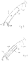
- FIG 3 shows the heating device 10 of Figure 1a mounted to the leading edge of a blade 200, such as a propeller blade. It will be appreciated that the illustrated heating device 10 could also be used to heat other products. In the field of aeronautics, for example, the heating device could be mounted to aircraft wings. The heating device 10 may also be mounted to wind turbine blades and the like, or indeed any to any surface that requires heating.
- first and second power terminals 42, 44 are connected to an electrical power source (not shown) such that electric current passes thought the electrically conductive fabric of the first and second plies 22, 24 to form a heating circuit. Heat is dissipated from the heater due to resistive heating of the electrically conductive fabric of the first and second plies 22, 24. The amount of heat energy provided by the heating device 10 may be controlled by adjusting the current in the heating circuit.
- the first and second plies 22, 24 may have different electrical properties or characteristics to one another in order to vary the power density across the device 10 and concentrate heating on a region or surface of the heating device 10.
- the thickness of the electrically conductive materials, the density of conductive fibres therein or the number of plies of the fabric might be varied.
- the heating device 10 may be formed from any number of additional plies 22, 24.
- the sheet 12 forming the device may itself be a multi-ply fabric resulting in multiple plies either side of the insulating material 30 to adapt heating requirement.
- the device 10 may be formed from 3 or more plies each being separated from the other plies by a sheet of insulating material 30. Additional plies could have different geometries to provide a desired distribution of heat.
- conductive woven fabrics may provide good heating homogeneity over the heating surface of the device.
- the heating device is arranged such that both power cables 42, 44 are positioned adjacent the blade root. Having both power cables 42, 44 at one end of the heater 10, particularly adjacent the root, may lower the risk of losing heater function in case of impact at the blade tip.
- Figure 4 shows an alternative configuration of the heating device 12 described above.
- Figure 4 shows a blade 200 incorporating three such heating devices 10a, 10b, 10c arranged adjacent to each other around the leading edge region of the blade 200.
- Such an arrangement allows the temperature to be varied across the leading edge region of the blade.
- the current supplied to each heating device 10a, 10b, 10c might be different depending on the heating requirement at that position on the blade.
- the conductive properties of the fabrics used for each device could also be varied in order to vary heating across the leading edge region of the blade 200.
- the device positioned at the leading edge might provide the most heat energy.
- Each heating device 10a. 10b, 10c might have its own power supply or they might each be connected to a common power supply.
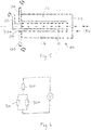
- FIG. 5 shows an alternative exemplary heating device 100.
- the heating device 100 includes a first portion 110 at an end 140 of the heating device 100 and three leg portions 112, 114, 116 extending from the first portion towards an opposed end 130 of the heating device 100.
- the legs 112, 114, 116 extend substantially parallel to each other and are approximately equal in width. It will be appreciated, however, that the legs 112, 114, 116 need not be straight or parallel to one another and may have differing widths depending on the heating requirements of the component the heater 100 is to be mounted to.
- the device 100 further includes three power terminals 120, 122, 124 attached to the legs 112, 114, 116 adjacent the first end 130 of the device 100. That is each leg has a power terminal connected thereto.
- the central leg 114 is connected to a negative terminal of a power source (not shown) via terminal 122 and the outer legs 112, 116 are connected to positive terminals of the power source via terminals 120, 124 such that current flows from the end of the central leg 114 towards the second end 140 of the device 100, through the first portion 110 and down each of the outer legs 112, 116.
- the outer legs 112, 116 may be connected to a negative terminal and the central leg 114 may be connected to a positive terminal. In such an arrangement, the current through the device 100 will be reversed.
- the first portion 110 and legs 112, 114, 116 of the device 100 are formed from an electrically conductive fabric as described with reference to the embodiment above.
- the device is formed from a single piece of fabric however it will be appreciated that the device may also be formed from multiple pieces of fabric suitably joined together in order to control the conductive properties of the various parts of the device 10 and therefore its heating properties.
- the device may also be formed from multiple plies of electrically conductive fabric.
- Heat is dissipated from the heating device 100 due to resistive heating of the electrically conductive fabric of the first and second plies 22, 24.
- the amount of heat energy provided by the heating device 10 may be controlled by adjusting the power in the heating circuit.
- Figure 6 shows a circuit diagram of the arrangement of Figure 5 .
- resistors 300, 310, 320 represent the three legs 112, 114, 116 of the device 100 described above.
- the heating of the device 100 may be varied by adjusting the width and resistive properties of the legs. While the illustrated embodiment shows three legs, it will be appreciated that any number of legs could be provided to alter the heating properties thereof.
- a heating device 10, 100 may be attached to a blade using an adhesive.
- the heating device 10, 100 might be attached to the outer surface of a blade to form a top layer thereof. Alternatively, the heating device might be coated with a further layer of paint or ice resistant coating or a metallic sheath to further protect the heating device 10, 100 from erosion and foreign object damage.
- the heating device 10, 100 may alternatively be incorporated into the material of the blade at an earlier stage of manufacture such that it is integrated into the structure of the blade. For example, one or more heating devices 10, 100 may be incorporated into the blade between the two outer plies of the blade shell.
Claims (9)
- Dispositif de chauffage (10 ; 100) comprenant :un tissu électriquement conducteur ; etdes première et seconde connexions électriques (42, 44 ; 120, 122, 124) connectées chacune au tissu électriquement conducteur à une première extrémité (15 ; 130) du dispositif (10 ; 100) de telle sorte que lorsque les connexions électriques (42, 44 ; 120, 122, 124) sont connectées à une source d'alimentation, le courant circule depuis la première connexion électrique (42 ; 122), à travers le tissu conducteur et vers la seconde connexion électrique (44 ; 120, 124), générant ainsi de la chaleur,
caractérisé en ce que :
le tissu conducteur comprend une première partie (110) et au moins trois jambes (112, 114, 116) reliées à et s'étendant depuis la première partie (110) jusqu'à la première extrémité (130) du dispositif (100), chacune des jambes (112, 114, 116) comprenant les première et seconde connexions électriques (120, 122, 124) à leurs extrémités, et l'une desdites jambes (114) étant connectée à une première borne d'une alimentation électrique et deux autres desdites jambes (112, 116) sont connectées à une seconde borne de l'alimentation. - Dispositif de chauffage selon la revendication 1, dans lequel les jambes (112, 114, 116) ont sensiblement la même longueur et sont espacées les unes des autres par un espace (115), l'espace (115) étant de même largeur le long de la longueur des jambes (112, 114, 116).
- Dispositif de chauffage selon l'une quelconque des revendications précédentes, dans lequel le tissu électriquement conducteur est un tissu tissé incorporant des fibres électriquement conductrices.
- Dispositif de chauffage selon l'une quelconque des revendications précédentes, dans lequel le tissu électriquement conducteur est fabriqué à partir d'un matériau en fibre de carbone.
- Dispositif de chauffage selon l'une quelconque des revendications précédentes, dans lequel le tissu électriquement conducteur est formé à partir d'une seule pièce de tissu électriquement conducteur.
- Composant (200) comprenant :une surface sujette à la formation de glace ; etle dispositif de chauffage (10 ; 100) selon l'une quelconque des revendications précédentes étant monté sur la surface.
- Composant selon la revendication 6, dans lequel le composant (200) est un produit aéronautique ou éolien tel qu'une aile d'avion, une pale d'hélice, une pale d'éolienne ou une pale de soufflante.
- Composant selon la revendication 6 ou 7, dans lequel le composant (200) est une pale ayant un pied et une pointe, les connexions électriques (42, 44 ; 120, 122, 124) du dispositif de chauffage (10 ; 100) étant positionnées à côté du pied de la pale (200).
- Composant selon la revendication 7 ou 8, dans lequel le dispositif de chauffage (10 ; 100) est monté sur un bord d'attaque du composant (200).
Priority Applications (2)
| Application Number | Priority Date | Filing Date | Title |
|---|---|---|---|
| EP16306064.3A EP3285545B1 (fr) | 2016-08-17 | 2016-08-17 | Dispositif de chauffage |
| US15/679,524 US11019687B2 (en) | 2016-08-17 | 2017-08-17 | Heating device |
Applications Claiming Priority (1)
| Application Number | Priority Date | Filing Date | Title |
|---|---|---|---|
| EP16306064.3A EP3285545B1 (fr) | 2016-08-17 | 2016-08-17 | Dispositif de chauffage |
Publications (2)
| Publication Number | Publication Date |
|---|---|
| EP3285545A1 EP3285545A1 (fr) | 2018-02-21 |
| EP3285545B1 true EP3285545B1 (fr) | 2020-05-06 |
Family
ID=56896492
Family Applications (1)
| Application Number | Title | Priority Date | Filing Date |
|---|---|---|---|
| EP16306064.3A Active EP3285545B1 (fr) | 2016-08-17 | 2016-08-17 | Dispositif de chauffage |
Country Status (2)
| Country | Link |
|---|---|
| US (1) | US11019687B2 (fr) |
| EP (1) | EP3285545B1 (fr) |
Families Citing this family (1)
| Publication number | Priority date | Publication date | Assignee | Title |
|---|---|---|---|---|
| CN114502840A (zh) | 2019-08-05 | 2022-05-13 | 维斯塔斯风力系统集团公司 | 加热风力涡轮机叶片 |
Family Cites Families (13)
| Publication number | Priority date | Publication date | Assignee | Title |
|---|---|---|---|---|
| US2503457A (en) * | 1947-04-04 | 1950-04-11 | Curtiss Wright Corp | Propeller blade deicing shoe |
| US3737618A (en) * | 1971-09-07 | 1973-06-05 | Park Ohio Industries Inc | Method and apparatus for resistance heating slotted tubes |
| FR2578377B1 (fr) * | 1984-12-26 | 1988-07-01 | Aerospatiale | Element chauffant de dispositif de degivrage d'une structure alaire, dispositif et son procede d'obtention |
| FR2744872B1 (fr) | 1996-02-08 | 1998-04-10 | Eurocopter France | Dispositif de chauffage d'un profil aerodynamique |
| JP4219790B2 (ja) * | 2003-11-14 | 2009-02-04 | 日本板硝子株式会社 | 電熱窓ガラス |
| AU2006252729A1 (en) | 2005-05-27 | 2006-12-07 | Bell Helicopter Textron Inc. | Strained capable conductive/resistive composite hybrid heater for thermal anti-ice device |
| US20060278631A1 (en) * | 2005-06-10 | 2006-12-14 | Challenge Carbon Technology Co., Ltd. Of Taiwan | Laminate fabric heater and method of making |
| US7157663B1 (en) | 2005-10-12 | 2007-01-02 | The Boeing Company | Conducting-fiber deicing systems and methods |
| FR2906786B1 (fr) | 2006-10-09 | 2009-11-27 | Eurocopter France | Procede et dispositif de degivrage d'une paroi d'aeronef |
| EP2340686B1 (fr) | 2008-10-14 | 2014-12-03 | Airbus Operations GmbH | Système de chauffage avec au moins une couche de chauffage électrothermique, une structure de construction comportant une telle couche de chauffage, un procédé de chauffage ainsi qu'un procédé de fabrication d'une pièce semi-finie ou d'une piéce comportant un telle appareillage de chauffage. |
| DE102011119844A1 (de) * | 2011-05-26 | 2012-12-13 | Eads Deutschland Gmbh | Verbundstruktur mit Eisschutzvorrichtung sowie Herstellverfahren |
| CN104507809A (zh) | 2012-05-16 | 2015-04-08 | 基德凯米公司 | 用感应或辐射对如风轮机叶片、飞机翼总体结构表面除冰 |
| EP2754891B1 (fr) * | 2013-01-14 | 2017-05-17 | Siemens Aktiengesellschaft | Système de dégivrage de pale de rotor d'éolienne |
-
2016
- 2016-08-17 EP EP16306064.3A patent/EP3285545B1/fr active Active
-
2017
- 2017-08-17 US US15/679,524 patent/US11019687B2/en active Active
Non-Patent Citations (1)
| Title |
|---|
| None * |
Also Published As
| Publication number | Publication date |
|---|---|
| EP3285545A1 (fr) | 2018-02-21 |
| US11019687B2 (en) | 2021-05-25 |
| US20180054859A1 (en) | 2018-02-22 |
Similar Documents
| Publication | Publication Date | Title |
|---|---|---|
| US10252806B2 (en) | Electrothermal heater mat | |
| EP2528817B1 (fr) | Appareil électrique pour un sytsem électro-thermique de protection de givrage | |
| US20120298803A1 (en) | Electrothermal heater | |
| US8807483B2 (en) | Electrothermal heater mat | |
| EP1885600B1 (fr) | Rechauffeur hybride composite conducteur/resistif pouvant supporter des contraintes elevees pour dispositif antigivreur thermique | |
| US7078658B2 (en) | Heater mat made of electrically-conductive fibers | |
| EP2528816B1 (fr) | Tapis chauffant comprenant un composant diélectrique avec connexion électrique | |
| CN110831858A (zh) | 电热加热器 | |
| BR112020005356B1 (pt) | Métodos para fabricar uma manta aquecedora eletrotérmica e um aparelho protegido contra gelo | |
| EP3285545B1 (fr) | Dispositif de chauffage | |
| EP2868575B1 (fr) | Pale de rotor avec interconnexions électriques | |
| CN110615107A (zh) | 可加热的前缘装置、前缘加热系统以及具有其的飞行器 | |
| US20200165919A1 (en) | Propeller blades | |
| US20200023975A1 (en) | De-icing apparatus | |
| JP7124053B2 (ja) | ヒータ素子およびヒータ素子を製造する方法 | |
| US20170275006A1 (en) | Blade heater mat insulation |
Legal Events
| Date | Code | Title | Description |
|---|---|---|---|
| PUAI | Public reference made under article 153(3) epc to a published international application that has entered the european phase |
Free format text: ORIGINAL CODE: 0009012 |
|
| STAA | Information on the status of an ep patent application or granted ep patent |
Free format text: STATUS: THE APPLICATION HAS BEEN PUBLISHED |
|
| AK | Designated contracting states |
Kind code of ref document: A1 Designated state(s): AL AT BE BG CH CY CZ DE DK EE ES FI FR GB GR HR HU IE IS IT LI LT LU LV MC MK MT NL NO PL PT RO RS SE SI SK SM TR |
|
| AX | Request for extension of the european patent |
Extension state: BA ME |
|
| STAA | Information on the status of an ep patent application or granted ep patent |
Free format text: STATUS: REQUEST FOR EXAMINATION WAS MADE |
|
| 17P | Request for examination filed |
Effective date: 20180821 |
|
| RBV | Designated contracting states (corrected) |
Designated state(s): AL AT BE BG CH CY CZ DE DK EE ES FI FR GB GR HR HU IE IS IT LI LT LU LV MC MK MT NL NO PL PT RO RS SE SI SK SM TR |
|
| GRAP | Despatch of communication of intention to grant a patent |
Free format text: ORIGINAL CODE: EPIDOSNIGR1 |
|
| STAA | Information on the status of an ep patent application or granted ep patent |
Free format text: STATUS: GRANT OF PATENT IS INTENDED |
|
| INTG | Intention to grant announced |
Effective date: 20191219 |
|
| GRAS | Grant fee paid |
Free format text: ORIGINAL CODE: EPIDOSNIGR3 |
|
| GRAA | (expected) grant |
Free format text: ORIGINAL CODE: 0009210 |
|
| STAA | Information on the status of an ep patent application or granted ep patent |
Free format text: STATUS: THE PATENT HAS BEEN GRANTED |
|
| AK | Designated contracting states |
Kind code of ref document: B1 Designated state(s): AL AT BE BG CH CY CZ DE DK EE ES FI FR GB GR HR HU IE IS IT LI LT LU LV MC MK MT NL NO PL PT RO RS SE SI SK SM TR |
|
| REG | Reference to a national code |
Ref country code: GB Ref legal event code: FG4D |
|
| REG | Reference to a national code |
Ref country code: CH Ref legal event code: EP Ref country code: AT Ref legal event code: REF Ref document number: 1268921 Country of ref document: AT Kind code of ref document: T Effective date: 20200515 |
|
| REG | Reference to a national code |
Ref country code: IE Ref legal event code: FG4D |
|
| REG | Reference to a national code |
Ref country code: DE Ref legal event code: R096 Ref document number: 602016035647 Country of ref document: DE |
|
| REG | Reference to a national code |
Ref country code: LT Ref legal event code: MG4D |
|
| REG | Reference to a national code |
Ref country code: NL Ref legal event code: MP Effective date: 20200506 |
|
| PG25 | Lapsed in a contracting state [announced via postgrant information from national office to epo] |
Ref country code: NO Free format text: LAPSE BECAUSE OF FAILURE TO SUBMIT A TRANSLATION OF THE DESCRIPTION OR TO PAY THE FEE WITHIN THE PRESCRIBED TIME-LIMIT Effective date: 20200806 Ref country code: GR Free format text: LAPSE BECAUSE OF FAILURE TO SUBMIT A TRANSLATION OF THE DESCRIPTION OR TO PAY THE FEE WITHIN THE PRESCRIBED TIME-LIMIT Effective date: 20200807 Ref country code: LT Free format text: LAPSE BECAUSE OF FAILURE TO SUBMIT A TRANSLATION OF THE DESCRIPTION OR TO PAY THE FEE WITHIN THE PRESCRIBED TIME-LIMIT Effective date: 20200506 Ref country code: SE Free format text: LAPSE BECAUSE OF FAILURE TO SUBMIT A TRANSLATION OF THE DESCRIPTION OR TO PAY THE FEE WITHIN THE PRESCRIBED TIME-LIMIT Effective date: 20200506 Ref country code: IS Free format text: LAPSE BECAUSE OF FAILURE TO SUBMIT A TRANSLATION OF THE DESCRIPTION OR TO PAY THE FEE WITHIN THE PRESCRIBED TIME-LIMIT Effective date: 20200906 Ref country code: PT Free format text: LAPSE BECAUSE OF FAILURE TO SUBMIT A TRANSLATION OF THE DESCRIPTION OR TO PAY THE FEE WITHIN THE PRESCRIBED TIME-LIMIT Effective date: 20200907 Ref country code: FI Free format text: LAPSE BECAUSE OF FAILURE TO SUBMIT A TRANSLATION OF THE DESCRIPTION OR TO PAY THE FEE WITHIN THE PRESCRIBED TIME-LIMIT Effective date: 20200506 |
|
| PG25 | Lapsed in a contracting state [announced via postgrant information from national office to epo] |
Ref country code: HR Free format text: LAPSE BECAUSE OF FAILURE TO SUBMIT A TRANSLATION OF THE DESCRIPTION OR TO PAY THE FEE WITHIN THE PRESCRIBED TIME-LIMIT Effective date: 20200506 Ref country code: LV Free format text: LAPSE BECAUSE OF FAILURE TO SUBMIT A TRANSLATION OF THE DESCRIPTION OR TO PAY THE FEE WITHIN THE PRESCRIBED TIME-LIMIT Effective date: 20200506 Ref country code: BG Free format text: LAPSE BECAUSE OF FAILURE TO SUBMIT A TRANSLATION OF THE DESCRIPTION OR TO PAY THE FEE WITHIN THE PRESCRIBED TIME-LIMIT Effective date: 20200806 Ref country code: RS Free format text: LAPSE BECAUSE OF FAILURE TO SUBMIT A TRANSLATION OF THE DESCRIPTION OR TO PAY THE FEE WITHIN THE PRESCRIBED TIME-LIMIT Effective date: 20200506 |
|
| REG | Reference to a national code |
Ref country code: AT Ref legal event code: MK05 Ref document number: 1268921 Country of ref document: AT Kind code of ref document: T Effective date: 20200506 |
|
| PG25 | Lapsed in a contracting state [announced via postgrant information from national office to epo] |
Ref country code: AL Free format text: LAPSE BECAUSE OF FAILURE TO SUBMIT A TRANSLATION OF THE DESCRIPTION OR TO PAY THE FEE WITHIN THE PRESCRIBED TIME-LIMIT Effective date: 20200506 Ref country code: NL Free format text: LAPSE BECAUSE OF FAILURE TO SUBMIT A TRANSLATION OF THE DESCRIPTION OR TO PAY THE FEE WITHIN THE PRESCRIBED TIME-LIMIT Effective date: 20200506 |
|
| PG25 | Lapsed in a contracting state [announced via postgrant information from national office to epo] |
Ref country code: RO Free format text: LAPSE BECAUSE OF FAILURE TO SUBMIT A TRANSLATION OF THE DESCRIPTION OR TO PAY THE FEE WITHIN THE PRESCRIBED TIME-LIMIT Effective date: 20200506 Ref country code: CZ Free format text: LAPSE BECAUSE OF FAILURE TO SUBMIT A TRANSLATION OF THE DESCRIPTION OR TO PAY THE FEE WITHIN THE PRESCRIBED TIME-LIMIT Effective date: 20200506 Ref country code: ES Free format text: LAPSE BECAUSE OF FAILURE TO SUBMIT A TRANSLATION OF THE DESCRIPTION OR TO PAY THE FEE WITHIN THE PRESCRIBED TIME-LIMIT Effective date: 20200506 Ref country code: SM Free format text: LAPSE BECAUSE OF FAILURE TO SUBMIT A TRANSLATION OF THE DESCRIPTION OR TO PAY THE FEE WITHIN THE PRESCRIBED TIME-LIMIT Effective date: 20200506 Ref country code: EE Free format text: LAPSE BECAUSE OF FAILURE TO SUBMIT A TRANSLATION OF THE DESCRIPTION OR TO PAY THE FEE WITHIN THE PRESCRIBED TIME-LIMIT Effective date: 20200506 Ref country code: IT Free format text: LAPSE BECAUSE OF FAILURE TO SUBMIT A TRANSLATION OF THE DESCRIPTION OR TO PAY THE FEE WITHIN THE PRESCRIBED TIME-LIMIT Effective date: 20200506 Ref country code: AT Free format text: LAPSE BECAUSE OF FAILURE TO SUBMIT A TRANSLATION OF THE DESCRIPTION OR TO PAY THE FEE WITHIN THE PRESCRIBED TIME-LIMIT Effective date: 20200506 Ref country code: DK Free format text: LAPSE BECAUSE OF FAILURE TO SUBMIT A TRANSLATION OF THE DESCRIPTION OR TO PAY THE FEE WITHIN THE PRESCRIBED TIME-LIMIT Effective date: 20200506 |
|
| REG | Reference to a national code |
Ref country code: DE Ref legal event code: R097 Ref document number: 602016035647 Country of ref document: DE |
|
| PG25 | Lapsed in a contracting state [announced via postgrant information from national office to epo] |
Ref country code: PL Free format text: LAPSE BECAUSE OF FAILURE TO SUBMIT A TRANSLATION OF THE DESCRIPTION OR TO PAY THE FEE WITHIN THE PRESCRIBED TIME-LIMIT Effective date: 20200506 Ref country code: SK Free format text: LAPSE BECAUSE OF FAILURE TO SUBMIT A TRANSLATION OF THE DESCRIPTION OR TO PAY THE FEE WITHIN THE PRESCRIBED TIME-LIMIT Effective date: 20200506 |
|
| REG | Reference to a national code |
Ref country code: DE Ref legal event code: R119 Ref document number: 602016035647 Country of ref document: DE |
|
| PLBE | No opposition filed within time limit |
Free format text: ORIGINAL CODE: 0009261 |
|
| STAA | Information on the status of an ep patent application or granted ep patent |
Free format text: STATUS: NO OPPOSITION FILED WITHIN TIME LIMIT |
|
| PG25 | Lapsed in a contracting state [announced via postgrant information from national office to epo] |
Ref country code: MC Free format text: LAPSE BECAUSE OF FAILURE TO SUBMIT A TRANSLATION OF THE DESCRIPTION OR TO PAY THE FEE WITHIN THE PRESCRIBED TIME-LIMIT Effective date: 20200506 |
|
| REG | Reference to a national code |
Ref country code: CH Ref legal event code: PL |
|
| 26N | No opposition filed |
Effective date: 20210209 |
|
| PG25 | Lapsed in a contracting state [announced via postgrant information from national office to epo] |
Ref country code: LU Free format text: LAPSE BECAUSE OF NON-PAYMENT OF DUE FEES Effective date: 20200817 Ref country code: LI Free format text: LAPSE BECAUSE OF NON-PAYMENT OF DUE FEES Effective date: 20200831 Ref country code: CH Free format text: LAPSE BECAUSE OF NON-PAYMENT OF DUE FEES Effective date: 20200831 |
|
| REG | Reference to a national code |
Ref country code: BE Ref legal event code: MM Effective date: 20200831 |
|
| PG25 | Lapsed in a contracting state [announced via postgrant information from national office to epo] |
Ref country code: SI Free format text: LAPSE BECAUSE OF FAILURE TO SUBMIT A TRANSLATION OF THE DESCRIPTION OR TO PAY THE FEE WITHIN THE PRESCRIBED TIME-LIMIT Effective date: 20200506 |
|
| PG25 | Lapsed in a contracting state [announced via postgrant information from national office to epo] |
Ref country code: DE Free format text: LAPSE BECAUSE OF NON-PAYMENT OF DUE FEES Effective date: 20210302 |
|
| PG25 | Lapsed in a contracting state [announced via postgrant information from national office to epo] |
Ref country code: BE Free format text: LAPSE BECAUSE OF NON-PAYMENT OF DUE FEES Effective date: 20200831 Ref country code: IE Free format text: LAPSE BECAUSE OF NON-PAYMENT OF DUE FEES Effective date: 20200817 |
|
| PG25 | Lapsed in a contracting state [announced via postgrant information from national office to epo] |
Ref country code: TR Free format text: LAPSE BECAUSE OF FAILURE TO SUBMIT A TRANSLATION OF THE DESCRIPTION OR TO PAY THE FEE WITHIN THE PRESCRIBED TIME-LIMIT Effective date: 20200506 Ref country code: MT Free format text: LAPSE BECAUSE OF FAILURE TO SUBMIT A TRANSLATION OF THE DESCRIPTION OR TO PAY THE FEE WITHIN THE PRESCRIBED TIME-LIMIT Effective date: 20200506 Ref country code: CY Free format text: LAPSE BECAUSE OF FAILURE TO SUBMIT A TRANSLATION OF THE DESCRIPTION OR TO PAY THE FEE WITHIN THE PRESCRIBED TIME-LIMIT Effective date: 20200506 |
|
| PG25 | Lapsed in a contracting state [announced via postgrant information from national office to epo] |
Ref country code: MK Free format text: LAPSE BECAUSE OF FAILURE TO SUBMIT A TRANSLATION OF THE DESCRIPTION OR TO PAY THE FEE WITHIN THE PRESCRIBED TIME-LIMIT Effective date: 20200506 |
|
| PGFP | Annual fee paid to national office [announced via postgrant information from national office to epo] |
Ref country code: GB Payment date: 20230720 Year of fee payment: 8 |
|
| PGFP | Annual fee paid to national office [announced via postgrant information from national office to epo] |
Ref country code: FR Payment date: 20230720 Year of fee payment: 8 |