EP3285541B1 - Identifier device - Google Patents
Identifier device Download PDFInfo
- Publication number
- EP3285541B1 EP3285541B1 EP15889103.6A EP15889103A EP3285541B1 EP 3285541 B1 EP3285541 B1 EP 3285541B1 EP 15889103 A EP15889103 A EP 15889103A EP 3285541 B1 EP3285541 B1 EP 3285541B1
- Authority
- EP
- European Patent Office
- Prior art keywords
- identification
- strap
- identification device
- locking projection
- transceiver module
- Prior art date
- Legal status (The legal status is an assumption and is not a legal conclusion. Google has not performed a legal analysis and makes no representation as to the accuracy of the status listed.)
- Active
Links
- 239000004020 conductor Substances 0.000 claims description 21
- 239000000463 material Substances 0.000 claims description 19
- 229920002943 EPDM rubber Polymers 0.000 claims description 15
- 238000000034 method Methods 0.000 claims description 13
- 229920001971 elastomer Polymers 0.000 claims description 10
- 229920003023 plastic Polymers 0.000 claims description 10
- 239000004033 plastic Substances 0.000 claims description 10
- 230000006854 communication Effects 0.000 claims description 7
- 238000004891 communication Methods 0.000 claims description 7
- -1 ethylene propylene diene Chemical class 0.000 claims description 7
- 239000000615 nonconductor Substances 0.000 claims description 6
- 229920002725 thermoplastic elastomer Polymers 0.000 claims description 5
- 238000003825 pressing Methods 0.000 claims description 3
- 230000000149 penetrating effect Effects 0.000 claims 1
- 239000004433 Thermoplastic polyurethane Substances 0.000 description 11
- 238000001746 injection moulding Methods 0.000 description 11
- 229920002803 thermoplastic polyurethane Polymers 0.000 description 11
- 229910000831 Steel Inorganic materials 0.000 description 7
- 239000010959 steel Substances 0.000 description 7
- 238000012544 monitoring process Methods 0.000 description 6
- 210000000707 wrist Anatomy 0.000 description 6
- 238000005299 abrasion Methods 0.000 description 5
- 210000003423 ankle Anatomy 0.000 description 4
- 230000007175 bidirectional communication Effects 0.000 description 4
- 231100000252 nontoxic Toxicity 0.000 description 4
- 230000003000 nontoxic effect Effects 0.000 description 4
- 229920000642 polymer Polymers 0.000 description 4
- 230000000284 resting effect Effects 0.000 description 4
- 239000004743 Polypropylene Substances 0.000 description 3
- 239000000945 filler Substances 0.000 description 3
- 238000004519 manufacturing process Methods 0.000 description 3
- 229920001155 polypropylene Polymers 0.000 description 3
- 230000008569 process Effects 0.000 description 3
- 239000000126 substance Substances 0.000 description 3
- 239000002253 acid Substances 0.000 description 2
- 150000007513 acids Chemical class 0.000 description 2
- 239000004676 acrylonitrile butadiene styrene Substances 0.000 description 2
- 239000002585 base Substances 0.000 description 2
- 230000004397 blinking Effects 0.000 description 2
- 239000003795 chemical substances by application Substances 0.000 description 2
- 238000009826 distribution Methods 0.000 description 2
- 238000005304 joining Methods 0.000 description 2
- 239000011159 matrix material Substances 0.000 description 2
- 239000000047 product Substances 0.000 description 2
- 230000002159 abnormal effect Effects 0.000 description 1
- 238000010521 absorption reaction Methods 0.000 description 1
- 230000004075 alteration Effects 0.000 description 1
- 230000005540 biological transmission Effects 0.000 description 1
- 239000007795 chemical reaction product Substances 0.000 description 1
- 239000003086 colorant Substances 0.000 description 1
- 230000008602 contraction Effects 0.000 description 1
- 230000006870 function Effects 0.000 description 1
- 238000002347 injection Methods 0.000 description 1
- 239000007924 injection Substances 0.000 description 1
- 239000011256 inorganic filler Substances 0.000 description 1
- 229910003475 inorganic filler Inorganic materials 0.000 description 1
- 239000000203 mixture Substances 0.000 description 1
- 238000012986 modification Methods 0.000 description 1
- 230000004048 modification Effects 0.000 description 1
- 230000035935 pregnancy Effects 0.000 description 1
- 230000004044 response Effects 0.000 description 1
- 230000001360 synchronised effect Effects 0.000 description 1
- 239000000454 talc Substances 0.000 description 1
- 229910052623 talc Inorganic materials 0.000 description 1
- 239000012815 thermoplastic material Substances 0.000 description 1
- XLYOFNOQVPJJNP-UHFFFAOYSA-N water Substances O XLYOFNOQVPJJNP-UHFFFAOYSA-N 0.000 description 1
- 238000003466 welding Methods 0.000 description 1
Images
Classifications
-
- G—PHYSICS
- G06—COMPUTING; CALCULATING OR COUNTING
- G06K—GRAPHICAL DATA READING; PRESENTATION OF DATA; RECORD CARRIERS; HANDLING RECORD CARRIERS
- G06K19/00—Record carriers for use with machines and with at least a part designed to carry digital markings
- G06K19/06—Record carriers for use with machines and with at least a part designed to carry digital markings characterised by the kind of the digital marking, e.g. shape, nature, code
- G06K19/067—Record carriers with conductive marks, printed circuits or semiconductor circuit elements, e.g. credit or identity cards also with resonating or responding marks without active components
- G06K19/07—Record carriers with conductive marks, printed circuits or semiconductor circuit elements, e.g. credit or identity cards also with resonating or responding marks without active components with integrated circuit chips
- G06K19/077—Constructional details, e.g. mounting of circuits in the carrier
- G06K19/07749—Constructional details, e.g. mounting of circuits in the carrier the record carrier being capable of non-contact communication, e.g. constructional details of the antenna of a non-contact smart card
- G06K19/07758—Constructional details, e.g. mounting of circuits in the carrier the record carrier being capable of non-contact communication, e.g. constructional details of the antenna of a non-contact smart card arrangements for adhering the record carrier to further objects or living beings, functioning as an identification tag
- G06K19/07762—Constructional details, e.g. mounting of circuits in the carrier the record carrier being capable of non-contact communication, e.g. constructional details of the antenna of a non-contact smart card arrangements for adhering the record carrier to further objects or living beings, functioning as an identification tag the adhering arrangement making the record carrier wearable, e.g. having the form of a ring, watch, glove or bracelet
-
- A—HUMAN NECESSITIES
- A44—HABERDASHERY; JEWELLERY
- A44C—PERSONAL ADORNMENTS, e.g. JEWELLERY; COINS
- A44C5/00—Bracelets; Wrist-watch straps; Fastenings for bracelets or wrist-watch straps
-
- G—PHYSICS
- G06—COMPUTING; CALCULATING OR COUNTING
- G06K—GRAPHICAL DATA READING; PRESENTATION OF DATA; RECORD CARRIERS; HANDLING RECORD CARRIERS
- G06K19/00—Record carriers for use with machines and with at least a part designed to carry digital markings
- G06K19/06—Record carriers for use with machines and with at least a part designed to carry digital markings characterised by the kind of the digital marking, e.g. shape, nature, code
- G06K19/067—Record carriers with conductive marks, printed circuits or semiconductor circuit elements, e.g. credit or identity cards also with resonating or responding marks without active components
- G06K19/07—Record carriers with conductive marks, printed circuits or semiconductor circuit elements, e.g. credit or identity cards also with resonating or responding marks without active components with integrated circuit chips
- G06K19/0723—Record carriers with conductive marks, printed circuits or semiconductor circuit elements, e.g. credit or identity cards also with resonating or responding marks without active components with integrated circuit chips the record carrier comprising an arrangement for non-contact communication, e.g. wireless communication circuits on transponder cards, non-contact smart cards or RFIDs
-
- G—PHYSICS
- G08—SIGNALLING
- G08B—SIGNALLING OR CALLING SYSTEMS; ORDER TELEGRAPHS; ALARM SYSTEMS
- G08B21/00—Alarms responsive to a single specified undesired or abnormal condition and not otherwise provided for
- G08B21/02—Alarms for ensuring the safety of persons
- G08B21/0202—Child monitoring systems using a transmitter-receiver system carried by the parent and the child
-
- G—PHYSICS
- G08—SIGNALLING
- G08B—SIGNALLING OR CALLING SYSTEMS; ORDER TELEGRAPHS; ALARM SYSTEMS
- G08B21/00—Alarms responsive to a single specified undesired or abnormal condition and not otherwise provided for
- G08B21/18—Status alarms
- G08B21/22—Status alarms responsive to presence or absence of persons
-
- G—PHYSICS
- G16—INFORMATION AND COMMUNICATION TECHNOLOGY [ICT] SPECIALLY ADAPTED FOR SPECIFIC APPLICATION FIELDS
- G16Z—INFORMATION AND COMMUNICATION TECHNOLOGY [ICT] SPECIALLY ADAPTED FOR SPECIFIC APPLICATION FIELDS, NOT OTHERWISE PROVIDED FOR
- G16Z99/00—Subject matter not provided for in other main groups of this subclass
-
- H—ELECTRICITY
- H04—ELECTRIC COMMUNICATION TECHNIQUE
- H04B—TRANSMISSION
- H04B7/00—Radio transmission systems, i.e. using radiation field
- H04B7/24—Radio transmission systems, i.e. using radiation field for communication between two or more posts
- H04B7/26—Radio transmission systems, i.e. using radiation field for communication between two or more posts at least one of which is mobile
-
- H—ELECTRICITY
- H04—ELECTRIC COMMUNICATION TECHNIQUE
- H04W—WIRELESS COMMUNICATION NETWORKS
- H04W4/00—Services specially adapted for wireless communication networks; Facilities therefor
- H04W4/02—Services making use of location information
- H04W4/021—Services related to particular areas, e.g. point of interest [POI] services, venue services or geofences
-
- H—ELECTRICITY
- H04—ELECTRIC COMMUNICATION TECHNIQUE
- H04W—WIRELESS COMMUNICATION NETWORKS
- H04W4/00—Services specially adapted for wireless communication networks; Facilities therefor
- H04W4/02—Services making use of location information
- H04W4/029—Location-based management or tracking services
-
- H—ELECTRICITY
- H04—ELECTRIC COMMUNICATION TECHNIQUE
- H04W—WIRELESS COMMUNICATION NETWORKS
- H04W4/00—Services specially adapted for wireless communication networks; Facilities therefor
- H04W4/30—Services specially adapted for particular environments, situations or purposes
- H04W4/33—Services specially adapted for particular environments, situations or purposes for indoor environments, e.g. buildings
-
- H—ELECTRICITY
- H04—ELECTRIC COMMUNICATION TECHNIQUE
- H04W—WIRELESS COMMUNICATION NETWORKS
- H04W84/00—Network topologies
- H04W84/18—Self-organising networks, e.g. ad-hoc networks or sensor networks
Definitions
- This invention relates to an identification and location device for an object or a person within a building, and more specifically a device having a compact smart identification strap associated with an object or person to identify the said object or person and further to track the location of that object or person inside a building.
- identification straps placed around a part of an object or a person whose location is to be tracked having locking means that attach the ends of the strap together to form a locked, unchangeable circumference large enough to fit comfortably around the object or person but small enough so that the strap does not slip off from the part of the object or person to which it has been fastened are known to the prior art.
- the locked circumference of the identification strap should be tight enough so that it does not loosen and slip off the child's wrist or ankle and so that it cannot be cut off.
- the identification strap no longer serves its purpose, in that it no longer identifies the child with the required degree of security, and indeed identification of the child may even be completely lost.
- Document US2007/0120687 discloses an identification device formed from a band of material and a non-reusable tamper-resistant fastening arranged to join opposite end regions of the band; wherein a Radio Frequency Identification (RFID) transponder is disposed in the band.
- RFID Radio Frequency Identification
- the transponder includes and RFID circuit and an antenna.
- the tamper-resistant fastening serves additional functions beyond securing the opposite end regions of the band together. Namely, the fastening can be made of an external conductive material and designed to create electrical continuity between multiple conductors to enable or disable certain circuit functionality.
- Document US2008/076389 discloses an automatic pairing method for a Bluetooth(R)-enabled mobile includes checking whether automatic authentication information has been received from a Bluetooth(R)-enabled appliance in response to an automatic pairing command, receiving pairing information from the Bluetooth(R)-enabled appliance and registering the Bluetooth(R)-enabled appliance as a slave if automatic authentication information is received, and establishing a Bluetooth(R) connection to the Bluetooth(R)-enabled appliance registered as a slave.
- This invention seeks to solve one or more of the disadvantages referred to above by means of an adjustable identification device as set forth in the claims.
- the adjustable identification device provides an identification kit that includes at least an electrically conductive identification strap for secure, adjustable circular locking of the identification strap so that it fits around a predetermined part of an object or person whose location is to be monitored; locking means; and a wireless communications transceiver module for establishing communication with other objects or persons inside a building.
- the transceiver of the identification device is designed to transmit and receive signals, including a unique identification signal, to and from a different identification device attached to a different object, such that both identification devices are linked and can be located within the same building.
- the transceiver executes the stored identification, linking, and location programs of the linked identification devices.
- the transceiver is further capable of being connected to a control unit for inputting data, including the identification and linkage values for the linked identification devices, into transceiver memory.
- a set of receivers is distributed at different points within the building, each of the receivers being capable of receiving signals, including identification signals, issued by the transceivers of the set of identification devices, and of transmitting the signals thus received to the control unit so as to establish the location of each identification device.
- the transceiver of the identification device is mechanically attached to the identification strap fastened onto the part of the object or person whose location is to be monitored, for example, on a mother's wrist or on a baby's wrist or ankle.
- the identification strap has a series of orifices made at either end of the strap to be able to adjust the size of the identification strap around the part of the object or person whose location is to be monitored when one end of the strap is brought up against the other end in order to lock the strap around the object or person whose location is to be monitored.
- the two ends of the identification strap are locked together by locking means made of a strip of flexible material having at one of its ends an orifice and at the opposite end a mechanical locking projection protruding outwards from the locking strip itself.
- the protruding locking projection comprises a member joined to the strip at one end that has an expanded portion at the distal end by way of a head, such that the head on the locking projection, pivotally attached to the end opposite the orifice on the locking means, can be removably inserted successively through a first orifice and a second orifice, respectively, at each end of the identification strap and finally inserted through the orifice on the locking means.
- the conductive identification strap is an elongated flexible laminated member made of a soft, non-toxic material such as a plastic polymeric material doped with an electrically conducting material, wherein the conductive doping material has been dispersed within a matrix of the polymeric material, such that the conductive material forms a conductive network that allows an electric current to flow.
- the identification strap is made from two different polymeric base materials, an ethylene propylene diene, or EPDM (ethylene propylene diene monomer [M-class]), rubber that is a thermoplastic elastomer with good abrasion and wear resistance and a thermoplastic polyurethane (TPU) with good flexibility over a broad range of temperatures.
- EPDM ethylene propylene diene monomer [M-class]
- TPU thermoplastic polyurethane
- Both the EPDM rubber and the TPU are doped with steel filaments (between 5 and 30 % by weight). These steel filament-doped plastics have good electrical conducting properties, very good resistance to atmospheric agents, acids, and bases, as well as to chemicals generally.
- the identification strap is manufactured using an injection moulding process that ensures that the outside of the identification strap is an electrical insulator while the inside is an electrical conductor, such that when the strap is fastened by the locking means, a closed electrical circuit is formed inside the identification strap. In manufacturing the identification strap, this feature is achieved without having to make any alterations to conventional injection moulding methods.
- the locking means is also an elongated flexible laminated member made of a soft, non-toxic material made from two different polymeric base materials, an ethylene propylene diene, or EPDM (ethylene propylene diene monomer [M-class]), rubber that is a thermoplastic elastomer with good abrasion and wear resistance and a thermoplastic polyurethane (TPU) with good flexibility over a broad range of temperatures.
- a soft, non-toxic material made from two different polymeric base materials, an ethylene propylene diene, or EPDM (ethylene propylene diene monomer [M-class])
- rubber that is a thermoplastic elastomer with good abrasion and wear resistance
- TPU thermoplastic polyurethane
- the locking projection further comprises a tubular member joining the head of the projection to the locking strip, such that when the identification device is closed, i.e., the locking means is also in the closed or working position, the tubular member of the projection is designed to be capable, in the said working position, of forming an electrical circuit having electrical continuity around a predetermined part of the object or person whose location is to be monitored.
- the tubular member of the mechanical locking projection comprises an electrically conductive material, such that the tubular member becomes part of the closed electric circuit that is formed when the locking means is in the working position, i.e., the locking means is closed so that it mechanically locks the two ends of the identification strap together when the mechanical locking projection is inserted through the two orifices in the identification strap and the orifice on the locking means.
- the locking means has a resting position in which the locking means is in the open position, i.e., the projection is not inserted into the orifice on the locking means.
- the mechanical locking of the identification strap and the locking means provides electrical continuity between the two ends of the conductive identification strap when the identification strap has been mounted, adjusted, and locked around a predetermined part of the object or person whose identity is to be monitored.
- the unidirectional locking projection is configured and arranged so as to allow the projection to be inserted through the orifice on the locking means and the two orifices on the identification strap all at once.
- the locking projection prevents the two ends of the identification strap from accidentally disengaging and breaking the closed electrical conductor thus formed.
- the identification device By operating in linked mode with at least one other identification device, the identification device makes possible more secure identification between the original object or person and at least one other object or person, the mother and at least one child to be monitored and interconnected.
- two objects or persons associated with two identification devices are discretely linked together by wireless communications established between the corresponding transceivers of the identification devices.
- the identification device enables a mother and at least one child to be independently and discretely identified, located, and tracked, making it possible to locate the two persons inside a building, such as a hospital.
- control unit is configured to detect departure from the said area by means of the receivers, wherein the control unit is also configured to transmit an alarm signal to a monitoring station in the building.
- control unit is further configured to transmit a further alarm signal to the monitoring station in the building.
- the control unit is designed for bidirectional communication with the receivers distributed around the building, and the receivers are also designed for bidirectional communication with the transceiver modules mounted in the identification devices.
- the identification device is wearable, adjustable, and tamper-resistant.
- the control unit is designed to implement a wide range of rules in order to provide assistance to the monitored persons by transmitting the corresponding alarm signal to signify an abnormal situation.
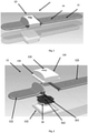
- Figures 1 and 2 show an adjustable identification device 11 that has an elongated flexible electrically conductive identification strap 12 for secure, adjustable circular locking around a predetermined part of an object or person whose identity is to be monitored, for example, a mother's wrist and a baby's ankle or wrist; a wireless communications transceiver module 31 for establishing wireless communication with at least one other identification device 11 within a pre-established area of a building, such as a hospital; and locking means 21 having two positions, a resting position associated with a position in which the identification device 11 is open and a working or closed position associated with a position in which the identification device 11 is closed or locked.
- a set of receivers is arranged at different points within the building, each of the receivers being capable of receiving signals, including identification signals transmitted by the transceiver module 31 of the identification device 11, and of transmitting the signals thus received to a control unit so as to establish the location of each identification device 11 within the building.
- the identification strap comprises a series of orifices 14 made at both ends of the identification strap 12 to be able to adjust the size of the identification strap 12 around the part of the object or person whose location is to be monitored when one end of the strap 12 is brought up against the other end of that same strap 12 in order to lock the strap around the object or person whose location is to be monitored, i.e., in the closed position of the strap 12.
- Distribution of the orifices 14 at either end of the strap 12 is as follows: for example, a single orifice at one of the ends and at least two orifices at the other end of the strap 12.
- locking means 21 is made from an elongated strip of flexible material 22 and comprises an orifice 23 at one end of the strip 22 and a protruding mechanical locking projection 24 pivotally attached to the opposite end of the strip 22 containing the orifice 23 in the locking means 21.
- the projection 24 comprises a tubular member with an expanded portion by way of a head 242 in the shape of a truncated cone at one end of the strip 22 of the locking means; i.e., the projection 24 has a mushroom-like shape.
- the unidirectional locking projection 24 is configured and arranged so as to allow the projection to be simultaneously inserted through the two orifices 14 on the strap and the orifice 23 on the strip of the locking means 21.
- the two ends of the identification strap 12 are fastened together by removably inserting the projection 21 successively through a first and a second orifice 14 respectively at either end of the identification strap and the orifice 23 on the locking means so as to lock the identification strap 12 closed and form a closed electrical circuit.
- the identification device 11 and the locking means 21 are in a resting position, i.e., open, or in a working or closed position, whereby the identification device 11 is locked around a predetermined part of the object or person whose identity is to be monitored.
- the identification strap can thus be fastened around a part of the object or person whose identity is to be monitored by mechanical locking of two orifices 14 on the identification strap 11, the orifice 21 on the locking means 21, and the projection 24 on the locking means.
- the identification strap 11 comprises an elongated flexible laminated member made of a soft, non-toxic material such as a plastic polymeric material that comprises an electrically conducting material dispersed in the polymeric matrix to create an electrical conductor over the length of the identification strap to enable an electric current supplied by an electric current source, such as a battery, to flow.
- a soft, non-toxic material such as a plastic polymeric material that comprises an electrically conducting material dispersed in the polymeric matrix to create an electrical conductor over the length of the identification strap to enable an electric current supplied by an electric current source, such as a battery, to flow.
- the identification strap 12 is made from two different polymeric base materials, an ethylene propylene diene, or EPDM (ethylene propylene diene monomer [M-class]), rubber that is a thermoplastic elastomer with good abrasion and wear resistance and a thermoplastic polyurethane (TPU) with good flexibility over a broad range of temperatures.
- EPDM ethylene propylene diene monomer [M-class]
- TPU thermoplastic polyurethane
- Both the EPDM rubber and the TPU are doped with steel filaments (between 5 and 30 % by weight). These steel filament-doped plastics have good electrical conducting properties, very good resistance to atmospheric agents, acids, and bases, as well as to chemicals generally.
- the identification strap 12 is manufactured by an injection moulding process designed to supply an identification strap that is an electrical insulator on the outside, the EPDM rubber having good electrical insulating features, and a conductor on the inside by reason of a high concentration of steel filaments present in the middle portion of the identification strap 12, such that when the strap is closed by the locking means 21, a closed electrical circuit is formed inside the identification strap 12.
- this feature is achieved without having to make any modifications to conventional injection moulding methods.
- the identification strap 12 is produced by a conventional injection moulding process. Depending on the injection rate and the temperature at which the plastic is injected, when a polymer loaded with a filler, especially a filler in the shape of filaments, is injected, a controlled distribution of the filament-filled polymer is achieved, such that the filaments are dispersed inside the identification strap 12 and the polymer is distributed on the outside of the identification strap 12, thereby insulating the inner portion where the dispersed filaments are located. Accordingly, an identification strap 12 that is an electrical insulator on the surface and an electrical conductor on the inside is obtained by optimising the rate at which the polymer and filament blend is injected together with the temperature of the plastic melt and the temperature of the mould.
- the locking means 21 is also an elongated flexible laminated member made of a soft, non-toxic material made from two different polymeric base materials, an ethylene propylene diene, or EPDM (ethylene propylene diene monomer [M-class]), rubber that is a thermoplastic elastomer with good abrasion and wear resistance and a thermoplastic polyurethane (TPU) with good flexibility over a broad range of temperatures.
- a soft, non-toxic material made from two different polymeric base materials, an ethylene propylene diene, or EPDM (ethylene propylene diene monomer [M-class])
- rubber that is a thermoplastic elastomer with good abrasion and wear resistance
- TPU thermoplastic polyurethane
- the locking projection 24 further comprises a tubular member 241 joining the head 242 of the projection to the locking strip 22, such that when the identification device 11 is closed, i.e., the locking means 24 is also in the closed or working position, the tubular member 241 of the projection 24 is designed to be capable, when the identification device 11 is in the working position, of forming an electrical circuit having electrical continuity around a predetermined part of the object or person whose location is to be monitored.
- the tubular member 241 of the mechanical locking projection 24 comprises an electrically conductive material, such that the tubular member 241 becomes part of the closed electric circuit that is formed when the locking means 21 is in the working position, i.e., the locking means 21 is closed so that it mechanically fastens the two ends of the identification strap 12 together when the mechanical locking projection is inserted through the two orifices in the identification strap and the orifice on the locking means.
- the locking means 21 has a resting position in which the locking means 21 is in the open position, i.e., the projection 24 is not inserted into the orifice 23 on the locking means.
- Figure 3 also shows the transceiver 31 module designed to be mounted inside a hollow case 13 made from two parts, an upper part 131 and a lower part 132 made of a strong plastic material such as acrylonitrile butadiene styrene (ABS).
- ABS acrylonitrile butadiene styrene
- the hollow case 13 has two openings 133, 134 in the opposing side walls for assembly of the two proximal ends 121, 122 of the identification strap 12.
- the two parts of the identification strap 12 are partially inserted into the opposing openings 133, 134 in the side of the hollow case 13, such that the transceiver module 31 is held in place by simultaneously being engaged by the two ends 121, 122 of the identification strap 12.
- the transceiver module 31 includes engagement means that are driven into the two proximal ends 121, 122, such that the engagement means penetrate a sufficient depth into the identification strap 12 to reach the middle portion of that strap 12 where the conductive material is dispersed, in order to achieve electrical continuity for the electrical circuit formed by the conductive material in the identification strap 12 itself.
- the engagement means are arranged so that the transceiver module 31 can be securely attached to the identification strap 12 and make electrical contact with the conductive material in the identification strap 12.
- the hollow case 13 is closed and sealed, for example, by ultrasonic welding.
- Both the identification strap 12 and the hollow case 13 may be made, for example, by overmoulding, i.e., the process whereby two components of different kinds or different colours are injected to form a single end product.
- overmoulding i.e., the process whereby two components of different kinds or different colours are injected to form a single end product.
- This is a two-step process in which, in a first step, one of the components is injected, and, in a second step, the mould or the part is turned and the second component is injected.
- the product is manufactured in a single process, as many injection moulding units are needed as there are components for the part.
- the hollow case 13 is manufactured from acrylonitrile butadiene styrene (ABS), which is a hard, rigid thermoplastic material that affords good impact resistance along with acceptable chemical resistance, low water absorption, and hence good dimensional stability and high abrasion resistance.
- ABS acrylonitrile butadiene styrene
- the hollow case 13 is manufactured from polypropylene (PP) loaded with 5-30 % talc or inorganic fillers.
- PP polypropylene
- PP is an extremely versatile plastic that broadly exhibits good thermal properties as well as hardness, and it is subject to less contraction when loaded with inorganic particulate filler.
- An alternative to overmoulding is to manufacture a pre-part on a conventional injection moulding machine with a single injection moulding assembly and then subsequently place the pre-part in a mould for overmoulding, as if injection moulding were being performed on an insert. This allows injection moulding of a two-component product on a simpler injection moulding machine.
- overmoulding yields an identification device 11 that comprises the identification strap 12 and the hollow case 13.
- the transceiver module 31 includes a source of an electric current to inject electric current through the engagement module, specifically, through some electrical output terminals of the transceiver module 31, such that the electric current injected is conducted by the electrical circuit formed by the conductive material to some electrical input terminals of the transceiver module 31.
- the electric current source supplies an electric current, at a predetermined value, to the electrical circuit formed inside the identification device 11.
- Both the input terminals and the output terminals are also connected to a control module included in the transceiver module 31, which is designed to detect both the absence and the presence of electrical current flowing through the electrical circuit formed in the identification strap 12 when the identification strap 12 has been closed, adjusted, and locked around the object or person whose location is to be monitored and the transceiver module 31 has been activated.
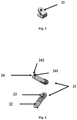
- the transceiver module 31 further includes a push button 311 and at least one light-emitting diode (LED) 312.
- the transceivers module 31 of both the first and the second identification device 11 may be linked, thereby making it possible to verify, at any time, that both identification devices 11 are present within a defined area inside the building.
- the linking procedure comprises the steps of assigning the first identification device 11 to an object or person whose identity is to be monitored, for example, a mother in a given area inside the building, for example, a hospital's maternity ward.
- a control unit is capable of locating the mother inside the building, because the transceiver module 31 of a first identification device 11 is capable of connecting to the control unit through a set of receivers arranged at different points within the building, each of the receivers being capable of receiving signals, including identification signals transmitted by the first transceiver module 31 of the identification device 11, and of transmitting the signals thus received to a control unit so as to establish the location of the first identification device 11 and, if appropriate, generate alarm signals.
- the second identification device 11 is assigned to a baby, and the second identification device 11 is linked to the first identification device 11 associated with the mother.
- the linking method comprises the steps of bringing the second identification device 11 into proximity with the first identification device 11, pushing the push button 311 of the second identification device 11 and holding it down for a time, such that the transceiver module 31 of a second identification device 11 switches to listening mode.
- This step in the linking or synchronisation procedure is indicated by the emission of light of a predetermined colour by the LED 312, indicating that the first and the second identification devices 11 are being linked. This status is indicated by blinking of the LED 312.
- the second transceiver 31 waits to receive an identification data stream from the first transceiver 31.
- the identification data stream has been received by the second transceiver 31, the linking method is complete. Completion of the procedure is indicated by a different predetermined colour and blinking by the LED 312.
- the first and second identification devices 11 are linked.
- All the identification devices 11 are, in their turn, connected to the control unit, such that the control unit can issue alarm warnings in certain defined cases of alert; furthermore, the control unit can be used to locate individuals and monitor mothers and their babies.
- the mother's master and the baby's slave identification devices can be synchronised by bringing the mother's and the baby's identification devices together and pressing and releasing the push button 311 on the mother's master or the baby's slave identification device 11.
- This status is indicated by a colour code produced by LED 312. For example, an orange LED indicates that synchronisation is in progress, and if the procedure achieves a positive outcome, the LED 312 emits a green light; if, by contrast, the procedure yields a negative outcome, the LED will emit a red light.
- Synchronisation may be performed from any identification device 11 without distinction. Linking can also be verified by bringing two identification devices 11 together and pressing and releasing push button 311.
- the transceiver module 31 of the first identification device 11 attached to an object or person whose identity and location are to be monitored is designed to execute a linking procedure by radio transmission of an identification data stream to the transceiver module 31 of the second identification device 11 attached to a different object or person.
- the transceiver module 31 of identification device 11 is configured to transmit and receive signals, including a unique identification signal, to and from a different identification device 11 attached to a different object or person, such that both identification devices 11 are linked and located within the same building.
- the transceiver module 31 executes the stored identification, linking, and location programs of the linked identification devices 11.
- the transceiver module 31 is further capable of being connected to the control unit for inputting data, including the identification and linkage values of the linked identification devices 11, into the memory of the transceiver module 31.
- a set of receivers is arranged at different points within the building, each of the receivers being capable of receiving signals, including identification signals, issued by the transceiver modules 31 of the set of identification devices 11, and of transmitting the signals thus received to the control unit so as to establish the location of each identification device 11 and generate alarm signals if appropriate.
- the identification device 11 enables linked objects or persons to identify, locate, and track each other, for example, a mother and child, making it possible to locate both persons within a predetermined area of the hospital and, if one of the persons is located outside that area or in an unauthorised area of the hospital, the control unit, which is linked to the linked identification devices by radio, is configured to generate an alarm signal to a pre-established hospital monitoring station.
- the transceiver module 31 of the identification strap is capable of detecting the absence of an electric current flowing through that electrical conductor and of sending a warning signal to a monitoring station through the receiver network distributed throughout the building.
- personnel in charge of the objects or persons whose identity is to be monitored may check the cause of the incident that has occurred and eliminate the cause that has given rise to the first alarm signal.
- control unit is configured to detect departure from the said area by means of the receivers, wherein the control unit is also configured to transmit an alarm signal to a monitoring station in the building.
- control unit is configured to further transmit an alarm signal to the building's monitoring station.
- the control unit is designed for bidirectional communication with the receivers distributed around the building, and the receivers, in their turn, engage in bidirectional communication with the transceiver modules 31 of the linked identification devices 11.
- Identification device 11 enables more secure identification of a newborn throughout the entire postnatal period following birth, throughout the hospitalisation period, until discharge from the hospital, thereby preventing switching of newborns.
- the identification device 11 further provides unique and definite mother-infant identification, coded by means of an alphanumeric code, both at the time of birth in the delivery room and during stays in other parts of the hospital.
Landscapes
- Engineering & Computer Science (AREA)
- Computer Networks & Wireless Communication (AREA)
- Signal Processing (AREA)
- Physics & Mathematics (AREA)
- General Physics & Mathematics (AREA)
- Computer Hardware Design (AREA)
- Microelectronics & Electronic Packaging (AREA)
- Theoretical Computer Science (AREA)
- Emergency Management (AREA)
- Business, Economics & Management (AREA)
- General Health & Medical Sciences (AREA)
- Child & Adolescent Psychology (AREA)
- Health & Medical Sciences (AREA)
- Radar Systems Or Details Thereof (AREA)
- Alarm Systems (AREA)
- Circuits Of Receivers In General (AREA)
Applications Claiming Priority (1)
| Application Number | Priority Date | Filing Date | Title |
|---|---|---|---|
| PCT/ES2015/070290 WO2016166383A1 (es) | 2015-04-13 | 2015-04-13 | Dispositivo identificador |
Publications (3)
| Publication Number | Publication Date |
|---|---|
| EP3285541A1 EP3285541A1 (en) | 2018-02-21 |
| EP3285541A4 EP3285541A4 (en) | 2019-01-09 |
| EP3285541B1 true EP3285541B1 (en) | 2022-03-23 |
Family
ID=57126058
Family Applications (1)
| Application Number | Title | Priority Date | Filing Date |
|---|---|---|---|
| EP15889103.6A Active EP3285541B1 (en) | 2015-04-13 | 2015-04-13 | Identifier device |
Country Status (5)
| Country | Link |
|---|---|
| US (1) | US10395160B2 (es) |
| EP (1) | EP3285541B1 (es) |
| ES (1) | ES2917499T3 (es) |
| MX (1) | MX369934B (es) |
| WO (1) | WO2016166383A1 (es) |
Families Citing this family (3)
| Publication number | Priority date | Publication date | Assignee | Title |
|---|---|---|---|---|
| US10431065B2 (en) * | 2016-02-05 | 2019-10-01 | Leola Brantley | Security and tracking systems and associated methods |
| US10096230B2 (en) * | 2016-06-06 | 2018-10-09 | Makusafe Corp | Safety device, system and method of use |
| US11200477B2 (en) * | 2019-07-31 | 2021-12-14 | Uatp Ip, Llc | Wearable RFID device |
Family Cites Families (18)
| Publication number | Priority date | Publication date | Assignee | Title |
|---|---|---|---|---|
| US5504474A (en) * | 1994-07-18 | 1996-04-02 | Elmo Tech Ltd. | Tag for electronic personnel monitoring |
| FR2791795B1 (fr) * | 1999-03-31 | 2001-10-19 | Jean Claude Mongrenier | Dispositif evolutif d'identification et tracabilite du sejour d'un malade dans un etablissement de soins |
| US8654018B2 (en) * | 2005-04-06 | 2014-02-18 | Vanguard Identificaiton Systems, Inc. | Printed planar RFID element wristbands and like personal identification devices |
| US6889620B2 (en) * | 2001-02-28 | 2005-05-10 | The Mosaic Company | Method for prescribing site-specific fertilizer application in agricultural fields |
| US20030016122A1 (en) * | 2001-07-19 | 2003-01-23 | Petrick Kathryn D. | Patient wristband form with built in RFID |
| US20030021014A1 (en) * | 2001-07-25 | 2003-01-30 | Motorola, Inc. | Linear optical amplifier and method for fabricating same |
| US6801476B2 (en) * | 2002-04-15 | 2004-10-05 | Daniel A. Gilmour | Wrist-worn phone and body-worn data storage device |
| US6853304B2 (en) * | 2002-05-07 | 2005-02-08 | Dmatek Ltd. | Monitoring device |
| US20070012068A1 (en) * | 2005-07-12 | 2007-01-18 | Kaplan Thomas G | Portable thermal treatment and storage units for containing readily accessible food or beverage items and methods for thermally treating food or beverage items |
| KR100711890B1 (ko) * | 2005-07-28 | 2007-04-25 | 삼성에스디아이 주식회사 | 유기 발광표시장치 및 그의 제조방법 |
| US7535356B2 (en) * | 2005-11-29 | 2009-05-19 | Bartronics America, Inc. | Identification band using a conductive fastening for enhanced security and functionality |
| US7417540B2 (en) * | 2006-04-17 | 2008-08-26 | Brk Brands, Inc. | Wireless linking of smoke/CO detection units |
| KR101307456B1 (ko) * | 2006-09-22 | 2013-09-11 | 삼성전자주식회사 | 휴대단말기에서 블루투스 자동등록을 제공하는 방법 및 장치 |
| US20080290176A1 (en) | 2007-05-22 | 2008-11-27 | Precision Dynamics Corporation | Methods and devices with a circuit for carrying information on a host |
| CN101448243B (zh) * | 2008-04-11 | 2011-09-21 | 中兴通讯股份有限公司 | 一种实现用户注册的方法 |
| US8485448B2 (en) | 2009-02-08 | 2013-07-16 | Itamar Medical Ltd. | Tamper-proof identification device particularly useful as a bracelet to be applied to the wrist or ankle of a patient |
| US8957777B2 (en) * | 2010-06-30 | 2015-02-17 | Welch Allyn, Inc. | Body area network pairing improvements for clinical workflows |
| US9064391B2 (en) * | 2011-12-20 | 2015-06-23 | Techip International Limited | Tamper-alert resistant bands for human limbs and associated monitoring systems and methods |
-
2015
- 2015-04-13 ES ES15889103T patent/ES2917499T3/es active Active
- 2015-04-13 US US15/566,569 patent/US10395160B2/en active Active
- 2015-04-13 MX MX2017013189A patent/MX369934B/es active IP Right Grant
- 2015-04-13 WO PCT/ES2015/070290 patent/WO2016166383A1/es active Application Filing
- 2015-04-13 EP EP15889103.6A patent/EP3285541B1/en active Active
Non-Patent Citations (1)
| Title |
|---|
| None * |
Also Published As
| Publication number | Publication date |
|---|---|
| EP3285541A4 (en) | 2019-01-09 |
| MX369934B (es) | 2019-11-26 |
| US20180096239A1 (en) | 2018-04-05 |
| US10395160B2 (en) | 2019-08-27 |
| ES2917499T3 (es) | 2022-07-08 |
| WO2016166383A1 (es) | 2016-10-20 |
| MX2017013189A (es) | 2018-05-22 |
| EP3285541A1 (en) | 2018-02-21 |
Similar Documents
| Publication | Publication Date | Title |
|---|---|---|
| EP3285541B1 (en) | Identifier device | |
| US6211790B1 (en) | Infant and parent matching and security system and method of matching infant and parent | |
| CN112969434B (zh) | 一种用于检测渗漏的具有导电性油墨电路的造口术器具 | |
| US5689240A (en) | Child monitor system | |
| US5936529A (en) | Electronic monitoring system | |
| US20100211080A1 (en) | Umbiliguard | |
| US20160078752A1 (en) | Tamper-alert and tamper-resistant band | |
| US5581234A (en) | Infant vehicle seat alarm system | |
| US7340809B2 (en) | Smart closure | |
| US7084764B2 (en) | System and method for monitoring location of an object | |
| EP3488432B1 (en) | Alarm triggering device and circuitry therefor | |
| US7292149B2 (en) | Electronic monitoring device | |
| US20170305340A1 (en) | Safety alert system | |
| US8708740B2 (en) | Waterproof radio accessory connector assembly | |
| EP3382664A1 (en) | Buckle for electronic surveillance device and method of opening the same | |
| CN112204935A (zh) | 建立患者监视器系统的蓝牙配对的方法和患者监视器系统 | |
| ZA200604044B (en) | Personal locator beacon | |
| US6317050B1 (en) | Water entry alarm system | |
| CN105701969A (zh) | 一种婴儿防盗智能手环装置 | |
| GB2368704A (en) | Wireless child distance monitoring alarm system with anti-tamper features | |
| US10461459B1 (en) | Switched electrical plug lock | |
| CN106230459B (zh) | 用于自动报警的手表 | |
| GB2569386A (en) | Fishing appliance controller | |
| GB2276025A (en) | Radio tag alarm system | |
| US9646475B2 (en) | Protective cover and alarm system for a latching system |
Legal Events
| Date | Code | Title | Description |
|---|---|---|---|
| STAA | Information on the status of an ep patent application or granted ep patent |
Free format text: STATUS: THE INTERNATIONAL PUBLICATION HAS BEEN MADE |
|
| PUAI | Public reference made under article 153(3) epc to a published international application that has entered the european phase |
Free format text: ORIGINAL CODE: 0009012 |
|
| STAA | Information on the status of an ep patent application or granted ep patent |
Free format text: STATUS: REQUEST FOR EXAMINATION WAS MADE |
|
| 17P | Request for examination filed |
Effective date: 20171005 |
|
| AK | Designated contracting states |
Kind code of ref document: A1 Designated state(s): AL AT BE BG CH CY CZ DE DK EE ES FI FR GB GR HR HU IE IS IT LI LT LU LV MC MK MT NL NO PL PT RO RS SE SI SK SM TR |
|
| AX | Request for extension of the european patent |
Extension state: BA ME |
|
| DAV | Request for validation of the european patent (deleted) | ||
| DAX | Request for extension of the european patent (deleted) | ||
| A4 | Supplementary search report drawn up and despatched |
Effective date: 20181211 |
|
| RIC1 | Information provided on ipc code assigned before grant |
Ipc: G06K 19/07 20060101ALI20181205BHEP Ipc: A44C 5/00 20060101ALI20181205BHEP Ipc: G06K 19/077 20060101AFI20181205BHEP Ipc: H04W 84/18 20090101ALI20181205BHEP Ipc: G06F 19/00 20180101ALI20181205BHEP |
|
| REG | Reference to a national code |
Ref country code: DE Ref legal event code: R079 Ref document number: 602015077785 Country of ref document: DE Free format text: PREVIOUS MAIN CLASS: H04W0084180000 Ipc: G06K0019077000 |
|
| STAA | Information on the status of an ep patent application or granted ep patent |
Free format text: STATUS: EXAMINATION IS IN PROGRESS |
|
| STAA | Information on the status of an ep patent application or granted ep patent |
Free format text: STATUS: EXAMINATION IS IN PROGRESS |
|
| RIC1 | Information provided on ipc code assigned before grant |
Ipc: A44C 5/00 20060101ALI20200915BHEP Ipc: G06K 19/077 20060101AFI20200915BHEP Ipc: H04W 84/18 20090101ALI20200915BHEP Ipc: G06K 19/07 20060101ALI20200915BHEP Ipc: H04W 4/021 20180101ALI20200915BHEP |
|
| 17Q | First examination report despatched |
Effective date: 20201005 |
|
| GRAP | Despatch of communication of intention to grant a patent |
Free format text: ORIGINAL CODE: EPIDOSNIGR1 |
|
| STAA | Information on the status of an ep patent application or granted ep patent |
Free format text: STATUS: GRANT OF PATENT IS INTENDED |
|
| INTG | Intention to grant announced |
Effective date: 20211015 |
|
| GRAS | Grant fee paid |
Free format text: ORIGINAL CODE: EPIDOSNIGR3 |
|
| GRAA | (expected) grant |
Free format text: ORIGINAL CODE: 0009210 |
|
| STAA | Information on the status of an ep patent application or granted ep patent |
Free format text: STATUS: THE PATENT HAS BEEN GRANTED |
|
| AK | Designated contracting states |
Kind code of ref document: B1 Designated state(s): AL AT BE BG CH CY CZ DE DK EE ES FI FR GB GR HR HU IE IS IT LI LT LU LV MC MK MT NL NO PL PT RO RS SE SI SK SM TR |
|
| REG | Reference to a national code |
Ref country code: GB Ref legal event code: FG4D |
|
| REG | Reference to a national code |
Ref country code: CH Ref legal event code: EP |
|
| REG | Reference to a national code |
Ref country code: DE Ref legal event code: R096 Ref document number: 602015077785 Country of ref document: DE |
|
| REG | Reference to a national code |
Ref country code: IE Ref legal event code: FG4D |
|
| REG | Reference to a national code |
Ref country code: AT Ref legal event code: REF Ref document number: 1477965 Country of ref document: AT Kind code of ref document: T Effective date: 20220415 |
|
| REG | Reference to a national code |
Ref country code: ES Ref legal event code: FG2A Ref document number: 2917499 Country of ref document: ES Kind code of ref document: T3 Effective date: 20220708 |
|
| REG | Reference to a national code |
Ref country code: LT Ref legal event code: MG9D |
|
| REG | Reference to a national code |
Ref country code: NL Ref legal event code: MP Effective date: 20220323 |
|
| PG25 | Lapsed in a contracting state [announced via postgrant information from national office to epo] |
Ref country code: SE Free format text: LAPSE BECAUSE OF FAILURE TO SUBMIT A TRANSLATION OF THE DESCRIPTION OR TO PAY THE FEE WITHIN THE PRESCRIBED TIME-LIMIT Effective date: 20220323 Ref country code: RS Free format text: LAPSE BECAUSE OF FAILURE TO SUBMIT A TRANSLATION OF THE DESCRIPTION OR TO PAY THE FEE WITHIN THE PRESCRIBED TIME-LIMIT Effective date: 20220323 Ref country code: NO Free format text: LAPSE BECAUSE OF FAILURE TO SUBMIT A TRANSLATION OF THE DESCRIPTION OR TO PAY THE FEE WITHIN THE PRESCRIBED TIME-LIMIT Effective date: 20220623 Ref country code: LT Free format text: LAPSE BECAUSE OF FAILURE TO SUBMIT A TRANSLATION OF THE DESCRIPTION OR TO PAY THE FEE WITHIN THE PRESCRIBED TIME-LIMIT Effective date: 20220323 Ref country code: HR Free format text: LAPSE BECAUSE OF FAILURE TO SUBMIT A TRANSLATION OF THE DESCRIPTION OR TO PAY THE FEE WITHIN THE PRESCRIBED TIME-LIMIT Effective date: 20220323 Ref country code: BG Free format text: LAPSE BECAUSE OF FAILURE TO SUBMIT A TRANSLATION OF THE DESCRIPTION OR TO PAY THE FEE WITHIN THE PRESCRIBED TIME-LIMIT Effective date: 20220623 |
|
| REG | Reference to a national code |
Ref country code: AT Ref legal event code: MK05 Ref document number: 1477965 Country of ref document: AT Kind code of ref document: T Effective date: 20220323 |
|
| PG25 | Lapsed in a contracting state [announced via postgrant information from national office to epo] |
Ref country code: LV Free format text: LAPSE BECAUSE OF FAILURE TO SUBMIT A TRANSLATION OF THE DESCRIPTION OR TO PAY THE FEE WITHIN THE PRESCRIBED TIME-LIMIT Effective date: 20220323 Ref country code: GR Free format text: LAPSE BECAUSE OF FAILURE TO SUBMIT A TRANSLATION OF THE DESCRIPTION OR TO PAY THE FEE WITHIN THE PRESCRIBED TIME-LIMIT Effective date: 20220624 Ref country code: FI Free format text: LAPSE BECAUSE OF FAILURE TO SUBMIT A TRANSLATION OF THE DESCRIPTION OR TO PAY THE FEE WITHIN THE PRESCRIBED TIME-LIMIT Effective date: 20220323 |
|
| PG25 | Lapsed in a contracting state [announced via postgrant information from national office to epo] |
Ref country code: NL Free format text: LAPSE BECAUSE OF FAILURE TO SUBMIT A TRANSLATION OF THE DESCRIPTION OR TO PAY THE FEE WITHIN THE PRESCRIBED TIME-LIMIT Effective date: 20220323 |
|
| PG25 | Lapsed in a contracting state [announced via postgrant information from national office to epo] |
Ref country code: SM Free format text: LAPSE BECAUSE OF FAILURE TO SUBMIT A TRANSLATION OF THE DESCRIPTION OR TO PAY THE FEE WITHIN THE PRESCRIBED TIME-LIMIT Effective date: 20220323 Ref country code: SK Free format text: LAPSE BECAUSE OF FAILURE TO SUBMIT A TRANSLATION OF THE DESCRIPTION OR TO PAY THE FEE WITHIN THE PRESCRIBED TIME-LIMIT Effective date: 20220323 Ref country code: RO Free format text: LAPSE BECAUSE OF FAILURE TO SUBMIT A TRANSLATION OF THE DESCRIPTION OR TO PAY THE FEE WITHIN THE PRESCRIBED TIME-LIMIT Effective date: 20220323 Ref country code: PT Free format text: LAPSE BECAUSE OF FAILURE TO SUBMIT A TRANSLATION OF THE DESCRIPTION OR TO PAY THE FEE WITHIN THE PRESCRIBED TIME-LIMIT Effective date: 20220725 Ref country code: EE Free format text: LAPSE BECAUSE OF FAILURE TO SUBMIT A TRANSLATION OF THE DESCRIPTION OR TO PAY THE FEE WITHIN THE PRESCRIBED TIME-LIMIT Effective date: 20220323 Ref country code: CZ Free format text: LAPSE BECAUSE OF FAILURE TO SUBMIT A TRANSLATION OF THE DESCRIPTION OR TO PAY THE FEE WITHIN THE PRESCRIBED TIME-LIMIT Effective date: 20220323 Ref country code: AT Free format text: LAPSE BECAUSE OF FAILURE TO SUBMIT A TRANSLATION OF THE DESCRIPTION OR TO PAY THE FEE WITHIN THE PRESCRIBED TIME-LIMIT Effective date: 20220323 |
|
| PG25 | Lapsed in a contracting state [announced via postgrant information from national office to epo] |
Ref country code: PL Free format text: LAPSE BECAUSE OF FAILURE TO SUBMIT A TRANSLATION OF THE DESCRIPTION OR TO PAY THE FEE WITHIN THE PRESCRIBED TIME-LIMIT Effective date: 20220323 Ref country code: IS Free format text: LAPSE BECAUSE OF FAILURE TO SUBMIT A TRANSLATION OF THE DESCRIPTION OR TO PAY THE FEE WITHIN THE PRESCRIBED TIME-LIMIT Effective date: 20220723 Ref country code: AL Free format text: LAPSE BECAUSE OF FAILURE TO SUBMIT A TRANSLATION OF THE DESCRIPTION OR TO PAY THE FEE WITHIN THE PRESCRIBED TIME-LIMIT Effective date: 20220323 |
|
| REG | Reference to a national code |
Ref country code: CH Ref legal event code: PL |
|
| REG | Reference to a national code |
Ref country code: DE Ref legal event code: R097 Ref document number: 602015077785 Country of ref document: DE |
|
| REG | Reference to a national code |
Ref country code: BE Ref legal event code: MM Effective date: 20220430 |
|
| PLBE | No opposition filed within time limit |
Free format text: ORIGINAL CODE: 0009261 |
|
| STAA | Information on the status of an ep patent application or granted ep patent |
Free format text: STATUS: NO OPPOSITION FILED WITHIN TIME LIMIT |
|
| PG25 | Lapsed in a contracting state [announced via postgrant information from national office to epo] |
Ref country code: MC Free format text: LAPSE BECAUSE OF FAILURE TO SUBMIT A TRANSLATION OF THE DESCRIPTION OR TO PAY THE FEE WITHIN THE PRESCRIBED TIME-LIMIT Effective date: 20220323 Ref country code: LU Free format text: LAPSE BECAUSE OF NON-PAYMENT OF DUE FEES Effective date: 20220413 Ref country code: LI Free format text: LAPSE BECAUSE OF NON-PAYMENT OF DUE FEES Effective date: 20220430 Ref country code: DK Free format text: LAPSE BECAUSE OF FAILURE TO SUBMIT A TRANSLATION OF THE DESCRIPTION OR TO PAY THE FEE WITHIN THE PRESCRIBED TIME-LIMIT Effective date: 20220323 Ref country code: CH Free format text: LAPSE BECAUSE OF NON-PAYMENT OF DUE FEES Effective date: 20220430 |
|
| PG25 | Lapsed in a contracting state [announced via postgrant information from national office to epo] |
Ref country code: BE Free format text: LAPSE BECAUSE OF NON-PAYMENT OF DUE FEES Effective date: 20220430 |
|
| 26N | No opposition filed |
Effective date: 20230102 |
|
| PG25 | Lapsed in a contracting state [announced via postgrant information from national office to epo] |
Ref country code: IE Free format text: LAPSE BECAUSE OF NON-PAYMENT OF DUE FEES Effective date: 20220413 |
|
| PG25 | Lapsed in a contracting state [announced via postgrant information from national office to epo] |
Ref country code: SI Free format text: LAPSE BECAUSE OF FAILURE TO SUBMIT A TRANSLATION OF THE DESCRIPTION OR TO PAY THE FEE WITHIN THE PRESCRIBED TIME-LIMIT Effective date: 20220323 |
|
| PG25 | Lapsed in a contracting state [announced via postgrant information from national office to epo] |
Ref country code: IT Free format text: LAPSE BECAUSE OF FAILURE TO SUBMIT A TRANSLATION OF THE DESCRIPTION OR TO PAY THE FEE WITHIN THE PRESCRIBED TIME-LIMIT Effective date: 20220323 |
|
| PGFP | Annual fee paid to national office [announced via postgrant information from national office to epo] |
Ref country code: DE Payment date: 20230420 Year of fee payment: 9 |
|
| PG25 | Lapsed in a contracting state [announced via postgrant information from national office to epo] |
Ref country code: HU Free format text: LAPSE BECAUSE OF FAILURE TO SUBMIT A TRANSLATION OF THE DESCRIPTION OR TO PAY THE FEE WITHIN THE PRESCRIBED TIME-LIMIT; INVALID AB INITIO Effective date: 20150413 |
|
| PG25 | Lapsed in a contracting state [announced via postgrant information from national office to epo] |
Ref country code: MK Free format text: LAPSE BECAUSE OF FAILURE TO SUBMIT A TRANSLATION OF THE DESCRIPTION OR TO PAY THE FEE WITHIN THE PRESCRIBED TIME-LIMIT Effective date: 20220323 Ref country code: CY Free format text: LAPSE BECAUSE OF FAILURE TO SUBMIT A TRANSLATION OF THE DESCRIPTION OR TO PAY THE FEE WITHIN THE PRESCRIBED TIME-LIMIT Effective date: 20220323 |
|
| PG25 | Lapsed in a contracting state [announced via postgrant information from national office to epo] |
Ref country code: TR Free format text: LAPSE BECAUSE OF FAILURE TO SUBMIT A TRANSLATION OF THE DESCRIPTION OR TO PAY THE FEE WITHIN THE PRESCRIBED TIME-LIMIT Effective date: 20220323 |
|
| PGFP | Annual fee paid to national office [announced via postgrant information from national office to epo] |
Ref country code: GB Payment date: 20240521 Year of fee payment: 10 |
|
| PGFP | Annual fee paid to national office [announced via postgrant information from national office to epo] |
Ref country code: ES Payment date: 20240513 Year of fee payment: 10 |
|
| PGFP | Annual fee paid to national office [announced via postgrant information from national office to epo] |
Ref country code: FR Payment date: 20240429 Year of fee payment: 10 |