EP3285503A1 - Method for preparing silica gel diaphragm, and silica gel diaphragm - Google Patents
Method for preparing silica gel diaphragm, and silica gel diaphragm Download PDFInfo
- Publication number
- EP3285503A1 EP3285503A1 EP15889072.3A EP15889072A EP3285503A1 EP 3285503 A1 EP3285503 A1 EP 3285503A1 EP 15889072 A EP15889072 A EP 15889072A EP 3285503 A1 EP3285503 A1 EP 3285503A1
- Authority
- EP
- European Patent Office
- Prior art keywords
- silica gel
- base material
- vibrating diaphragm
- liquid silica
- layers
- Prior art date
- Legal status (The legal status is an assumption and is not a legal conclusion. Google has not performed a legal analysis and makes no representation as to the accuracy of the status listed.)
- Granted
Links
Images


Classifications
-
- H—ELECTRICITY
- H04—ELECTRIC COMMUNICATION TECHNIQUE
- H04R—LOUDSPEAKERS, MICROPHONES, GRAMOPHONE PICK-UPS OR LIKE ACOUSTIC ELECTROMECHANICAL TRANSDUCERS; ELECTRIC HEARING AIDS; PUBLIC ADDRESS SYSTEMS
- H04R31/00—Apparatus or processes specially adapted for the manufacture of transducers or diaphragms therefor
- H04R31/003—Apparatus or processes specially adapted for the manufacture of transducers or diaphragms therefor for diaphragms or their outer suspension
-
- B—PERFORMING OPERATIONS; TRANSPORTING
- B29—WORKING OF PLASTICS; WORKING OF SUBSTANCES IN A PLASTIC STATE IN GENERAL
- B29C—SHAPING OR JOINING OF PLASTICS; SHAPING OF MATERIAL IN A PLASTIC STATE, NOT OTHERWISE PROVIDED FOR; AFTER-TREATMENT OF THE SHAPED PRODUCTS, e.g. REPAIRING
- B29C43/00—Compression moulding, i.e. applying external pressure to flow the moulding material; Apparatus therefor
- B29C43/22—Compression moulding, i.e. applying external pressure to flow the moulding material; Apparatus therefor of articles of indefinite length
- B29C43/24—Calendering
-
- B—PERFORMING OPERATIONS; TRANSPORTING
- B29—WORKING OF PLASTICS; WORKING OF SUBSTANCES IN A PLASTIC STATE IN GENERAL
- B29C—SHAPING OR JOINING OF PLASTICS; SHAPING OF MATERIAL IN A PLASTIC STATE, NOT OTHERWISE PROVIDED FOR; AFTER-TREATMENT OF THE SHAPED PRODUCTS, e.g. REPAIRING
- B29C43/00—Compression moulding, i.e. applying external pressure to flow the moulding material; Apparatus therefor
- B29C43/22—Compression moulding, i.e. applying external pressure to flow the moulding material; Apparatus therefor of articles of indefinite length
- B29C43/24—Calendering
- B29C43/245—Adjusting calender parameters, e.g. bank quantity
-
- B—PERFORMING OPERATIONS; TRANSPORTING
- B29—WORKING OF PLASTICS; WORKING OF SUBSTANCES IN A PLASTIC STATE IN GENERAL
- B29C—SHAPING OR JOINING OF PLASTICS; SHAPING OF MATERIAL IN A PLASTIC STATE, NOT OTHERWISE PROVIDED FOR; AFTER-TREATMENT OF THE SHAPED PRODUCTS, e.g. REPAIRING
- B29C43/00—Compression moulding, i.e. applying external pressure to flow the moulding material; Apparatus therefor
- B29C43/22—Compression moulding, i.e. applying external pressure to flow the moulding material; Apparatus therefor of articles of indefinite length
- B29C43/28—Compression moulding, i.e. applying external pressure to flow the moulding material; Apparatus therefor of articles of indefinite length incorporating preformed parts or layers, e.g. compression moulding around inserts or for coating articles
-
- B—PERFORMING OPERATIONS; TRANSPORTING
- B29—WORKING OF PLASTICS; WORKING OF SUBSTANCES IN A PLASTIC STATE IN GENERAL
- B29C—SHAPING OR JOINING OF PLASTICS; SHAPING OF MATERIAL IN A PLASTIC STATE, NOT OTHERWISE PROVIDED FOR; AFTER-TREATMENT OF THE SHAPED PRODUCTS, e.g. REPAIRING
- B29C43/00—Compression moulding, i.e. applying external pressure to flow the moulding material; Apparatus therefor
- B29C43/22—Compression moulding, i.e. applying external pressure to flow the moulding material; Apparatus therefor of articles of indefinite length
- B29C43/30—Making multilayered or multicoloured articles
-
- B—PERFORMING OPERATIONS; TRANSPORTING
- B29—WORKING OF PLASTICS; WORKING OF SUBSTANCES IN A PLASTIC STATE IN GENERAL
- B29C—SHAPING OR JOINING OF PLASTICS; SHAPING OF MATERIAL IN A PLASTIC STATE, NOT OTHERWISE PROVIDED FOR; AFTER-TREATMENT OF THE SHAPED PRODUCTS, e.g. REPAIRING
- B29C43/00—Compression moulding, i.e. applying external pressure to flow the moulding material; Apparatus therefor
- B29C43/32—Component parts, details or accessories; Auxiliary operations
- B29C43/58—Measuring, controlling or regulating
-
- H—ELECTRICITY
- H04—ELECTRIC COMMUNICATION TECHNIQUE
- H04R—LOUDSPEAKERS, MICROPHONES, GRAMOPHONE PICK-UPS OR LIKE ACOUSTIC ELECTROMECHANICAL TRANSDUCERS; ELECTRIC HEARING AIDS; PUBLIC ADDRESS SYSTEMS
- H04R7/00—Diaphragms for electromechanical transducers; Cones
- H04R7/02—Diaphragms for electromechanical transducers; Cones characterised by the construction
- H04R7/04—Plane diaphragms
- H04R7/06—Plane diaphragms comprising a plurality of sections or layers
-
- B—PERFORMING OPERATIONS; TRANSPORTING
- B29—WORKING OF PLASTICS; WORKING OF SUBSTANCES IN A PLASTIC STATE IN GENERAL
- B29K—INDEXING SCHEME ASSOCIATED WITH SUBCLASSES B29B, B29C OR B29D, RELATING TO MOULDING MATERIALS OR TO MATERIALS FOR MOULDS, REINFORCEMENTS, FILLERS OR PREFORMED PARTS, e.g. INSERTS
- B29K2105/00—Condition, form or state of moulded material or of the material to be shaped
- B29K2105/0058—Liquid or visquous
- B29K2105/0061—Gel or sol
-
- B—PERFORMING OPERATIONS; TRANSPORTING
- B29—WORKING OF PLASTICS; WORKING OF SUBSTANCES IN A PLASTIC STATE IN GENERAL
- B29L—INDEXING SCHEME ASSOCIATED WITH SUBCLASS B29C, RELATING TO PARTICULAR ARTICLES
- B29L2031/00—Other particular articles
- B29L2031/38—Loudspeaker cones; Acoustic diaphragms
-
- H—ELECTRICITY
- H04—ELECTRIC COMMUNICATION TECHNIQUE
- H04R—LOUDSPEAKERS, MICROPHONES, GRAMOPHONE PICK-UPS OR LIKE ACOUSTIC ELECTROMECHANICAL TRANSDUCERS; ELECTRIC HEARING AIDS; PUBLIC ADDRESS SYSTEMS
- H04R2307/00—Details of diaphragms or cones for electromechanical transducers, their suspension or their manufacture covered by H04R7/00 or H04R31/003, not provided for in any of its subgroups
- H04R2307/023—Diaphragms comprising ceramic-like materials, e.g. pure ceramic, glass, boride, nitride, carbide, mica and carbon materials
-
- H—ELECTRICITY
- H04—ELECTRIC COMMUNICATION TECHNIQUE
- H04R—LOUDSPEAKERS, MICROPHONES, GRAMOPHONE PICK-UPS OR LIKE ACOUSTIC ELECTROMECHANICAL TRANSDUCERS; ELECTRIC HEARING AIDS; PUBLIC ADDRESS SYSTEMS
- H04R2307/00—Details of diaphragms or cones for electromechanical transducers, their suspension or their manufacture covered by H04R7/00 or H04R31/003, not provided for in any of its subgroups
- H04R2307/025—Diaphragms comprising polymeric materials
-
- H—ELECTRICITY
- H04—ELECTRIC COMMUNICATION TECHNIQUE
- H04R—LOUDSPEAKERS, MICROPHONES, GRAMOPHONE PICK-UPS OR LIKE ACOUSTIC ELECTROMECHANICAL TRANSDUCERS; ELECTRIC HEARING AIDS; PUBLIC ADDRESS SYSTEMS
- H04R7/00—Diaphragms for electromechanical transducers; Cones
- H04R7/02—Diaphragms for electromechanical transducers; Cones characterised by the construction
- H04R7/04—Plane diaphragms
- H04R7/06—Plane diaphragms comprising a plurality of sections or layers
- H04R7/10—Plane diaphragms comprising a plurality of sections or layers comprising superposed layers in contact
-
- H—ELECTRICITY
- H04—ELECTRIC COMMUNICATION TECHNIQUE
- H04R—LOUDSPEAKERS, MICROPHONES, GRAMOPHONE PICK-UPS OR LIKE ACOUSTIC ELECTROMECHANICAL TRANSDUCERS; ELECTRIC HEARING AIDS; PUBLIC ADDRESS SYSTEMS
- H04R7/00—Diaphragms for electromechanical transducers; Cones
- H04R7/16—Mounting or tensioning of diaphragms or cones
- H04R7/18—Mounting or tensioning of diaphragms or cones at the periphery
Definitions
- the present disclosure relates to the technical field of electronic products, and particularly, to a method for fabricating silica gel vibrating diaphragm and a silica gel vibrating diaphragm.
- silica gel vibrating diaphragms are usually injection molded.
- this molding mode has a high cost and a low efficiency, and the vibrating diaphragm is thick (usually more than 50 ⁇ m) due to the limitation of the injection molding conditions.
- the mold adjustment is complex in the injection molding process, which is adverse to quick product development.
- the present disclosure is proposed to provide a method for fabricating silica gel vibrating diaphragm and a silica gel vibrating diaphragm, which can overcome or at least partially solve the above problem.
- the technical solutions of the present disclosure are realized as follows:
- the forming a composite material belt by using two layers of a base material and liquid silica gel in a calendering manner comprises:
- the method comprises during the coating the liquid silica gel onto the lower layer base material by a glue applicator, reserving a gap not coated with the liquid silica gel at an edge of the lower layer base material; and after the adjusting a thickness of the liquid silica gel by a thickness control device, when laying the other layer of the base material on the liquid silica gel to serve as the upper layer base material, aligning an edge of the upper layer base material with the edge of the lower layer base material.
- the liquid silica gel is made by sufficiently mixing two silica gel preparing solutions in proportion.
- the two layers of the base material are one or two of polyetheretherketone (PEEK), polyethylene terephthalate (PET), polyetherimide (PEI), and thermoplastic polyurethanes (TPU).
- PEEK polyetheretherketone
- PET polyethylene terephthalate
- PEI polyetherimide
- TPU thermoplastic polyurethanes
- an embodiment of the present disclosure provides a silica gel vibrating diaphragm, fabricated by:
- the composite material belt is fabricated by:
- a gap not coated with the liquid silica gel is reserved at an edge of the lower layer base material and an edge of the upper layer base material.
- the liquid silica gel for fabricating the silica gel vibrating diaphragm is made by sufficiently mixing two silica gel preparing solutions in proportion.
- the two layers of the base material for fabricating the silica gel vibrating diaphragm are one or two of polyetheretherketone (PEEK), polyethylene terephthalate (PET), polyetherimide (PEI), and thermoplastic polyurethanes (TPU).
- PEEK polyetheretherketone
- PET polyethylene terephthalate
- PEI polyetherimide
- TPU thermoplastic polyurethanes
- the present disclosure discloses a method for fabricating silica gel vibrating diaphragm and a silica gel vibrating diaphragm.
- the method performs a material bet composition for two layers of a base material and liquid silica gel in a calendering manner, molds the obtained composite material belt in a hot-press molding manner, removes the upper layer base material and the lower layer base material after the molding, and blanks the whole sheet of silica gel vibrating diaphragm that has been removed of the base material, thereby fabricating the required silica gel vibrating diaphragm.
- this technical solution has the advantages off simple molding manner, and controllable thickness of the vibrating diaphragm (the minimum thickness is 5 ⁇ m).
- this technical solution since the vibrating diaphragm die holder used in the molding process has a lower cost and more styles than the injection die used in conventional technical solutions, this technical solution further has the advantages of low cost and various styles of the vibrating diaphragm.
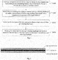
- Fig. 1 is a flow diagram of a method for fabricating a silica gel vibrating diaphragm provided by an embodiment of the present disclosure. The method comprises:
- Fig. 2 is a schematic diagram of a composite material belt fabricated in a calendering manner provided by an embodiment of the present disclosure, and the liquid silica gel in Fig. 2 is between an upper layer base material and a lower layer base material.
- the calendering is a process of fabricating a semi-finished product such as a glue sheet by putting a heated rubber compound through the gap between two rollers arranged horizontally and rotated relative to each other.
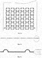
- Figs. 3-a and 3-b are schematic diagrams of a composite material belt after hot-press molding provided by an embodiment of the present disclosure.
- the liquid silica gel is vulcanization molded in a manner of hot-press molding, wherein the number of the vibrating diaphragm die holders may be adjusted according to the area and molding state of the composite material belt.
- the vibrating diaphragm die holder in this step may be single or plural.
- this technical solution molds the composite material belt with the vibrating diaphragm die holder, which does not only reduces the production cost, but also conveniently obtains vibrating diaphragms of various shapes.
- this step successfully gets rid of the two layers of the base material, and obtains an undamaged and whole sheet of silica gel vibrating diaphragm.
- Fig. 5 is a schematic diagram of a blanked silica gel vibrating diaphragm provided by an embodiment of the present disclosure.
- the silica gel vibrating diaphragm obtained in the method of the embodiment has the advantages of simple molding manner, low cost, various styles of the vibrating diaphragm, and small thickness of the vibrating diaphragm.
- the obtained composite material belt may be calendered up through a belt scroll bar for the convenience of the storage of the composite material belt.
- Fig. 7 is a schematic diagram of a composite material belt having liquid silica gel received between two layers of a base material provided by an embodiment of the present disclosure.
- the method comprises during the coating the liquid silica gel onto the lower layer base material by a glue applicator, reserving a gap not coated with the liquid silica gel at the edge of the lower layer base material; and after the adjusting a thickness of the liquid silica gel by a thickness control device, when laying the other layer of the base material on the liquid silica gel to serve as the upper layer base material, aligning an edge of the upper layer base material with the edge of the lower layer base material.
- liquid silica gel in this technical solution is made by sufficiently mixing two silica gel preparing solutions in proportion.
- Fig. 8 is a schematic diagram of preparing liquid silica gel, wherein two silica gel preparing solutions are put in two separate containers and sufficiently mixed in a preset proportion, so as to obtain the required liquid silica gel.
- the two layers of the base material in this technical solution may be one or two of polyetheretherketone (PEEK), polyethylene terephthalate (PET), polyetherimide (PEI), and thermoplastic polyurethanes (TPU).
- PEEK polyetheretherketone
- PET polyethylene terephthalate
- PEI polyetherimide
- TPU thermoplastic polyurethanes
- polyetheretherketone is a linear aromatic high molecular compound with its molecular backbone containing chain links, and it is semicrystalline thermoplastic special engineering plastic. As compared with other special engineering plastics, it has the advantages such as a temperature resistance of 260 ⁇ , excellent mechanical property, good self-lubricating property, chemical resistance, flame retardance, delamination resistance, heat resistance, non-resistance to strong nitric acid and concentrated sulphuric acid, radiation resistance, and ultra-strong mechanical property.
- PET Polyethylene terephthalate
- PEI Polyetherimide
- PEI Polyetherimide
- TPU Thermoplastic polyurethanes
- TPU has the advantages such as wide hardness range, high mechanical strength, strong cold endurance, good processability, oil resistance, water resistance and mycete resistance. It is widely used in the fields of commodities, sports goods, toys, decorative materials, etc.
- the present disclosure further provides a silica gel vibrating diaphragm, which is fabricated by:
- the composite material belt is formed by:
- a gap not coated with the liquid silica gel is reserved at the edges of the lower layer base material and the upper layer base material.
- liquid silica gel in this embodiment is made by sufficiently mixing two silica gel preparing solutions in proportion.
- silica gel preparing solutions are put in two separate containers, and sufficiently mixed in a preset proportion, so as to obtain the required liquid silica gel.
- the two layers of the base material in this technical solution may be one or two of polyetheretherketone (PEEK), polyethylene terephthalate (PET), polyetherimide (PEI), and thermoplastic polyurethanes (TPU).
- PEEK polyetheretherketone
- PET polyethylene terephthalate
- PEI polyetherimide
- TPU thermoplastic polyurethanes
- the present disclosure discloses a method for fabricating silica gel vibrating diaphragm and a silica gel vibrating diaphragm.
- the method performs a material bet composition for two layers of a base material and liquid silica gel in a calendering manner, molds the obtained composite material belt in a hot-press molding manner, removes the upper layer base material and the lower layer base material after the molding, and blanks the whole sheet of silica gel vibrating diaphragm that has been removed of the base material, thereby fabricating the required silica gel vibrating diaphragm.
- this technical solution has the advantages of simple molding manner, and controllable thickness of the vibrating diaphragm (the minimum thickness is 5 ⁇ m).
- this technical solution since the vibrating diaphragm die holder used in the molding process has a lower cost and more styles than the injection die used in conventional technical solutions, this technical solution further has the advantages of low cost and various styles of the vibrating diaphragm.
Landscapes
- Engineering & Computer Science (AREA)
- Mechanical Engineering (AREA)
- Physics & Mathematics (AREA)
- Acoustics & Sound (AREA)
- Signal Processing (AREA)
- Manufacturing & Machinery (AREA)
- Multimedia (AREA)
- Laminated Bodies (AREA)
- Casting Or Compression Moulding Of Plastics Or The Like (AREA)
- Paper (AREA)
- Compositions Of Macromolecular Compounds (AREA)
- Diaphragms For Electromechanical Transducers (AREA)
Abstract
Description
- This application is a continuation of International Application No.
PCT/CN2015/097960, filed on December 18, 2015 201510175913.1, filed on April 14, 2015 - The present disclosure relates to the technical field of electronic products, and particularly, to a method for fabricating silica gel vibrating diaphragm and a silica gel vibrating diaphragm.
- Currently, silica gel vibrating diaphragms are usually injection molded. However, this molding mode has a high cost and a low efficiency, and the vibrating diaphragm is thick (usually more than 50µm) due to the limitation of the injection molding conditions. In addition, the mold adjustment is complex in the injection molding process, which is adverse to quick product development.
- In view of the above problem, the present disclosure is proposed to provide a method for fabricating silica gel vibrating diaphragm and a silica gel vibrating diaphragm, which can overcome or at least partially solve the above problem. The technical solutions of the present disclosure are realized as follows:
- In one aspect, an embodiment of the present disclosure provides a method for fabricating a silica gel vibrating diaphragm, comprising:
- forming a composite material belt by using two layers of a base material and liquid silica gel in a calendering manner, wherein the liquid silica gel is between the two layers of the base material;
- wholly hot-press molding the composite material belt by a vibrating diaphragm die holder, a temperature of the hot-press molding being higher than a vulcanization temperature of the liquid silica gel;
- removing the two layers of the base material to obtain a whole sheet of silica gel vibrating diaphragm; and
- blanking the whole sheet of silica gel vibrating diaphragm that has been removed of the two layers of the base material to fabricate a required silica gel vibrating diaphragm.
- Preferably, the forming a composite material belt by using two layers of a base material and liquid silica gel in a calendering manner comprises:
- placing one layer of the base material at a bottom layer to serve as a lower layer base material, and coating the liquid silica gel onto the lower layer base material by a glue applicator;
- adjusting a thickness of the liquid silica gel by a thickness control device, and laying the other layer of the base material on the liquid silica gel to serve as an upper layer base material; and
- performing pressure maintaining processing for the lower layer base material, the liquid silica gel and the upper layer base material by a pressure maintaining shaft to obtain the composite material belt.
- Preferably, the method comprises during the coating the liquid silica gel onto the lower layer base material by a glue applicator, reserving a gap not coated with the liquid silica gel at an edge of the lower layer base material; and
after the adjusting a thickness of the liquid silica gel by a thickness control device, when laying the other layer of the base material on the liquid silica gel to serve as the upper layer base material, aligning an edge of the upper layer base material with the edge of the lower layer base material. - Preferably, the liquid silica gel is made by sufficiently mixing two silica gel preparing solutions in proportion.
- Preferably, the two layers of the base material are one or two of polyetheretherketone (PEEK), polyethylene terephthalate (PET), polyetherimide (PEI), and thermoplastic polyurethanes (TPU).
- In another aspect, an embodiment of the present disclosure provides a silica gel vibrating diaphragm, fabricated by:
- forming a composite material belt by using two layers of a base material and liquid silica gel in a calendering manner, wherein the liquid silica gel is between the two layers of the base material;
- wholly hot-press molding the composite material belt by a vibrating diaphragm die holder, a temperature of the hot-press molding being higher than a vulcanization temperature of the liquid silica gel;
- removing the two layers of the base material to obtain a whole sheet of silica gel vibrating diaphragm; and
- blanking the whole sheet of silica gel vibrating diaphragm that has been removed of the two layers of the base material to fabricate a required silica gel vibrating diaphragm.
- Preferably, the composite material belt is fabricated by:
- placing one layer of the base material at a bottom layer to serve as a lower layer base material, and coating the liquid silica gel onto the lower layer base material by a glue applicator;
- adjusting a thickness of the liquid silica gel by a thickness control device, and laying the other layer of the base material on the liquid silica gel to serve as an upper layer base material; and
- performing pressure maintaining processing for the lower layer base material, the liquid silica gel and the upper layer base material by a pressure maintaining shaft to obtain the composite material belt.
- Preferably, a gap not coated with the liquid silica gel is reserved at an edge of the lower layer base material and an edge of the upper layer base material.
- Preferably, the liquid silica gel for fabricating the silica gel vibrating diaphragm is made by sufficiently mixing two silica gel preparing solutions in proportion.
- Preferably, the two layers of the base material for fabricating the silica gel vibrating diaphragm are one or two of polyetheretherketone (PEEK), polyethylene terephthalate (PET), polyetherimide (PEI), and thermoplastic polyurethanes (TPU).
- The embodiments of the present disclosure have the following beneficial effects: the present disclosure discloses a method for fabricating silica gel vibrating diaphragm and a silica gel vibrating diaphragm. The method performs a material bet composition for two layers of a base material and liquid silica gel in a calendering manner, molds the obtained composite material belt in a hot-press molding manner, removes the upper layer base material and the lower layer base material after the molding, and blanks the whole sheet of silica gel vibrating diaphragm that has been removed of the base material, thereby fabricating the required silica gel vibrating diaphragm. As compared with conventional technical solutions, this technical solution has the advantages off simple molding manner, and controllable thickness of the vibrating diaphragm (the minimum thickness is 5µm). In addition, in this technical solution, since the vibrating diaphragm die holder used in the molding process has a lower cost and more styles than the injection die used in conventional technical solutions, this technical solution further has the advantages of low cost and various styles of the vibrating diaphragm.
- The above descriptions are just generalizations of the technical solutions of the present disclosure, and in order to understand the technical means of the present disclosure more clearly, the specific embodiments of the present disclosure are illustrated as follows.
- The drawings are provided for a further understanding of the present disclosure, and constitute part of the Specification. The drawings are used together with the embodiments of the present disclosure to explain the present disclosure, rather than making any limitation to the present disclosure. In the drawings,
-
Fig. 1 is a flow diagram of a method for fabricating a silica gel vibrating diaphragm provided by an embodiment of the present disclosure; -
Fig. 2 is a schematic diagram of a composite material belt fabricated in a calendering manner provided by an embodiment of the present disclosure; -
Fig. 3-a is a schematic diagram of a whole sheet of composite material belt after hot-press molding provided by an embodiment of the present disclosure; -
Fig. 3-b is a side view of a composite material belt after hot-press molding along a section line A-A provided by an embodiment of the present disclosure; -
Fig. 4-a is a schematic diagram of part of a vulcanized composite material belt provided by an embodiment of the present disclosure; -
Fig. 4-b is a schematic diagram of a silica gel vibrating diaphragm that has been removed of base material provided by an embodiment of the present disclosure; -
Fig. 5 is a schematic diagram of a blanked silica gel vibrating diaphragm provided by an embodiment of the present disclosure; -
Fig. 6 is a schematic diagram of fabricating a composite material belt in a calendering manner provided by an embodiment of the present disclosure; -
Fig. 7 is a schematic diagram of a composite material belt having liquid silica gel received between two layers of a base material provided by an embodiment of the present disclosure; and -
Fig. 8 is a schematic diagram of preparing liquid silica gel. - In order that the objectives, technical solutions and advantages of the present disclosure are clearer, the embodiments of the present disclosure will be further described in details as follows with reference to the drawings.
-
Fig. 1 is a flow diagram of a method for fabricating a silica gel vibrating diaphragm provided by an embodiment of the present disclosure. The method comprises: - S100: forming a composite material belt by using two layers of a base material and liquid silica gel in a calendering manner, wherein the liquid silica gel is between the two layers of the base material.
- As illustrated in
Fig. 2, Fig. 2 is a schematic diagram of a composite material belt fabricated in a calendering manner provided by an embodiment of the present disclosure, and the liquid silica gel inFig. 2 is between an upper layer base material and a lower layer base material. - In that, the calendering is a process of fabricating a semi-finished product such as a glue sheet by putting a heated rubber compound through the gap between two rollers arranged horizontally and rotated relative to each other.
- S200: wholly hot-press molding the composite material belt by a vibrating diaphragm die holder, a temperature of the hot-press molding being higher than a vulcanization temperature of the liquid silica gel.
- As illustrated in
Figs. 3-a and 3-b, Figs. 3-a and 3-b are schematic diagrams of a composite material belt after hot-press molding provided by an embodiment of the present disclosure. - In this step, the liquid silica gel is vulcanization molded in a manner of hot-press molding, wherein the number of the vibrating diaphragm die holders may be adjusted according to the area and molding state of the composite material belt. In practical applications, the vibrating diaphragm die holder in this step may be single or plural.
- Since the vibrating diaphragm die holder has a lower cost than injection dies, this technical solution molds the composite material belt with the vibrating diaphragm die holder, which does not only reduces the production cost, but also conveniently obtains vibrating diaphragms of various shapes.
- S300: removing the two layers of the base material to obtain a whole sheet of silica gel vibrating diaphragm.
- As illustrated in
Figs. 4-a and4-b ,Figs. 4-a and4-b are schematic diagrams of part of the vulcanized composite material belt and the silica gel vibrating diaphragm that has been removed of base material, respectively. - By employing the incompatibility between the vulcanized silica gel and the base material, this step successfully gets rid of the two layers of the base material, and obtains an undamaged and whole sheet of silica gel vibrating diaphragm.
- S400: blanking the whole sheet of silica gel vibrating diaphragm that has been removed of the two layers of the base material to fabricate a required silica gel vibrating diaphragm.
- As illustrated in
Fig. 5, Fig. 5 is a schematic diagram of a blanked silica gel vibrating diaphragm provided by an embodiment of the present disclosure. - As compared with the conventional injection molded silica gel vibrating diaphragm, the silica gel vibrating diaphragm obtained in the method of the embodiment has the advantages of simple molding manner, low cost, various styles of the vibrating diaphragm, and small thickness of the vibrating diaphragm.
- Next, a specific embodiment will be provided to in detail describe how to apply the conventional calendering process into the fabrication of the vibrating diaphragm.
- As illustrated in
Fig. 6, Fig. 6 is a schematic diagram of fabricating a composite material belt in a calendering manner provided by an embodiment of the present disclosure, and specifically, the following manner is adopted to fabricate the composite material belt: - placing one layer of the base material at a bottom layer to serve as a lower layer base material, and coating the liquid silica gel onto the lower layer base material by a glue applicator;
- during the coating the liquid silica gel onto the lower layer base material, the thickness of the liquid silica gel may be non-uniform, and the coating thickness may not coincide with the required thickness of the liquid silica gel; thus, this technical solution adjusts the thickness of the liquid silica gel by a thickness control device to solve the problem that the thickness of the liquid silica gel cannot be accurately controlled during coating the liquid silica gel;
- while the thickness control device is adjusting the thickness of the liquid silica gel, laying the other layer of the base material on the liquid silica gel to serve as an upper layer base material; and
- performing pressure maintaining processing for the lower layer base material, the liquid silica gel and the upper layer base material by a pressure maintaining shaft to obtain the composite material belt.
- In practical applications, the obtained composite material belt may be calendered up through a belt scroll bar for the convenience of the storage of the composite material belt.
- In this embodiment, in order to conveniently remove the upper layer base material and the lower layer base material, and sufficiently utilize all the liquid silica gel, the liquid silica gel is received between the two layers of the base material when the material belt composition is made for the two layers of the base material and the liquid silica gel.
- As illustrated in
Fig. 7, Fig. 7 is a schematic diagram of a composite material belt having liquid silica gel received between two layers of a base material provided by an embodiment of the present disclosure. The method comprises during the coating the liquid silica gel onto the lower layer base material by a glue applicator, reserving a gap not coated with the liquid silica gel at the edge of the lower layer base material; and after the adjusting a thickness of the liquid silica gel by a thickness control device, when laying the other layer of the base material on the liquid silica gel to serve as the upper layer base material, aligning an edge of the upper layer base material with the edge of the lower layer base material. - To be noted, the liquid silica gel in this technical solution is made by sufficiently mixing two silica gel preparing solutions in proportion.
- As illustrated in
Fig. 8, Fig. 8 is a schematic diagram of preparing liquid silica gel, wherein two silica gel preparing solutions are put in two separate containers and sufficiently mixed in a preset proportion, so as to obtain the required liquid silica gel. - To be further noted, the two layers of the base material in this technical solution may be one or two of polyetheretherketone (PEEK), polyethylene terephthalate (PET), polyetherimide (PEI), and thermoplastic polyurethanes (TPU).
- In that, polyetheretherketone (PEEK) is a linear aromatic high molecular compound with its molecular backbone containing chain links, and it is semicrystalline thermoplastic special engineering plastic. As compared with other special engineering plastics, it has the advantages such as a temperature resistance of 260□, excellent mechanical property, good self-lubricating property, chemical resistance, flame retardance, delamination resistance, heat resistance, non-resistance to strong nitric acid and concentrated sulphuric acid, radiation resistance, and ultra-strong mechanical property.
- Polyethylene terephthalate (PET) is a milky white or pale yellow and high-crystalline polymer, with its surface smooth and glossy. It has excellent physical and mechanical properties within a wide temperature range. The long-term usage temperature reaches 120□, the electrical insulation is excellent and the electrical property is still good even under high temperature and high frequency, the creep resistance, fatigue resistance, rub resistance and dimensional stability are all fine, and only the corona resistance is poor.
- Polyetherimide (PEI) is an amber transparent solid. It has very strong high-temperature stability, and even a non-enhanced PEI still has good toughness and strength. Due to the superior thermal stability, PEI may be used to make high temperature heat resistant devices. Further, PEI has excellent mechanical property, electrical insulation property, radiation resistant property, and high and low temperatures and wear resistant properties, and can be passed by microwaves. PEI also has favorable characteristics of flame retardance, chemical reaction resistance and electric insulation. In addition, PEI may also form a heat-resistant high-molecular alloy together with other engineering plastics, and may be used for a long term under the operating temperature of - 160∼180°C.
- Thermoplastic polyurethanes (TPU) are mainly classified into a polyester type and a polyether type. TPU has the advantages such as wide hardness range, high mechanical strength, strong cold endurance, good processability, oil resistance, water resistance and mycete resistance. It is widely used in the fields of commodities, sports goods, toys, decorative materials, etc.
- Based on the same technical conception as the method for fabricating a silica gel vibrating diaphragm, the present disclosure further provides a silica gel vibrating diaphragm, which is fabricated by:
- forming a composite material belt by using two layers of a base material and liquid silica gel in a calendering manner, wherein the liquid silica gel is between the two layers of the base material;
- wholly hot-press molding the composite material belt by a vibrating diaphragm die holder, a temperature of the hot-press molding being higher than a vulcanization temperature of the liquid silica gel;
- removing the two layers of the base material to obtain a whole sheet of silica gel vibrating diaphragm; and
- blanking the whole sheet of silica gel vibrating diaphragm that has been removed of the two layers of the base material to fabricate a required silica gel vibrating diaphragm.
- The composite material belt is formed by:
- placing one layer of the base material at a bottom layer to serve as a lower layer base material, and coating the liquid silica gel onto the lower layer base material by a glue applicator;
- adjusting a thickness of the liquid silica gel by a thickness control device, and laying the other layer of the base material on the liquid silica gel to serve as an upper layer base material; and
- performing pressure maintaining processing for the lower layer base material, the liquid silica gel and the upper layer base material by a pressure maintaining shaft to obtain the composite material belt.
- Preferably, a gap not coated with the liquid silica gel is reserved at the edges of the lower layer base material and the upper layer base material.
- To be noted, the liquid silica gel in this embodiment is made by sufficiently mixing two silica gel preparing solutions in proportion.
- For example, two silica gel preparing solutions are put in two separate containers, and sufficiently mixed in a preset proportion, so as to obtain the required liquid silica gel.
- To be further noted, the two layers of the base material in this technical solution may be one or two of polyetheretherketone (PEEK), polyethylene terephthalate (PET), polyetherimide (PEI), and thermoplastic polyurethanes (TPU).
- In conclusion, the present disclosure discloses a method for fabricating silica gel vibrating diaphragm and a silica gel vibrating diaphragm. The method performs a material bet composition for two layers of a base material and liquid silica gel in a calendering manner, molds the obtained composite material belt in a hot-press molding manner, removes the upper layer base material and the lower layer base material after the molding, and blanks the whole sheet of silica gel vibrating diaphragm that has been removed of the base material, thereby fabricating the required silica gel vibrating diaphragm. As compared with conventional technical solutions, this technical solution has the advantages of simple molding manner, and controllable thickness of the vibrating diaphragm (the minimum thickness is 5µm). In addition, in this technical solution, since the vibrating diaphragm die holder used in the molding process has a lower cost and more styles than the injection die used in conventional technical solutions, this technical solution further has the advantages of low cost and various styles of the vibrating diaphragm.
- The above descriptions are just preferred embodiments of the present disclosure, rather than limitations to the protection scope of the present disclosure. Any amendment, equivalent replacement, improvement, etc. made within the spirit and principle of the present disclosure shall fall within the protection scope of the present disclosure.
Claims (10)
- A method for fabricating a silica gel vibrating diaphragm, characterized in that the method comprising:forming a composite material belt by using two layers of a base material and liquid silica gel in a calendering manner, wherein the liquid silica gel is between the two layers of the base material;wholly hot-press molding the composite material belt by a vibrating diaphragm die holder, a temperature of the hot-press molding being higher than a vulcanization temperature of the liquid silica gel;removing the two layers of the base material to obtain a whole sheet of silica gel vibrating diaphragm; andblanking the whole sheet of silica gel vibrating diaphragm that has been removed of the two layers of the base material to fabricate a required silica gel vibrating diaphragm.
- The method according to claim 1, characterized in that the forming a composite material belt by using two layers of a base material and liquid silica gel in a calendering manner comprises:placing one layer of the base material at a bottom layer to serve as a lower layer base material, and coating the liquid silica gel onto the lower layer base material by a glue applicator;adjusting a thickness of the liquid silica gel by a thickness control device, and laying the other layer of the base material on the liquid silica gel to serve as an upper layer base material; andperforming pressure maintaining processing for the lower layer base material, the liquid silica gel and the upper layer base material by a pressure maintaining shaft to obtain the composite material belt.
- The method according to claim 2, characterized in that during the coating the liquid silica gel onto the lower layer base material by a glue applicator, reserving a gap not coated with the liquid silica gel at an edge of the lower layer base material; and
after the adjusting a thickness of the liquid silica gel by a thickness control device, when laying the other layer of the base material on the liquid silica gel to serve as the upper layer base material, aligning an edge of the upper layer base material with the edge of the lower layer base material. - The method according to any one of claims 1 to 3, characterized in that the liquid silica gel is made by sufficiently mixing two silica gel preparing solutions in proportion.
- The method according to claim 4, characterized in that the two layers of the base material are one or two of polyetheretherketone (PEEK), polyethylene terephthalate (PET), polyetherimide (PEI), and thermoplastic polyurethanes (TPU).
- A silica gel vibrating diaphragm, characterized in that the silica gel vibrating diaphragm fabricated by:forming a composite material belt by using two layers of a base material and liquid silica gel in a calendering manner, wherein the liquid silica gel is between the two layers of the base material;wholly hot-press molding the composite material belt by a vibrating diaphragm die holder, a temperature of the hot-press molding being higher than a vulcanization temperature of the liquid silica gel;removing the two layers of the base material to obtain a whole sheet of silica gel vibrating diaphragm; andblanking the whole sheet of silica gel vibrating diaphragm that has been removed of the two layers of the base material to fabricate a required silica gel vibrating diaphragm.
- The silica gel vibrating diaphragm according to claim 6, characterized in that the composite material belt is fabricated by:placing one layer of the base material at a bottom layer to serve as a lower layer base material, and coating the liquid silica gel onto the lower layer base material by a glue applicator;adjusting a thickness of the liquid silica gel by a thickness control device, and laying the other layer of the base material on the liquid silica gel to serve as an upper layer base material; andperforming pressure maintaining processing for the lower layer base material, the liquid silica gel and the upper layer base material by a pressure maintaining shaft to obtain the composite material belt.
- The silica gel vibrating diaphragm according to claim 7, characterized in that a gap not coated with the liquid silica gel is reserved at an edge of the lower layer base material and an edge of the upper layer base material.
- The silica gel vibrating diaphragm according to any one of claims 6 to 8, characterized in that the liquid silica gel for fabricating the silica gel vibrating diaphragm is made by sufficiently mixing two silica gel preparing solutions in proportion.
- The silica gel vibrating diaphragm according to claim 9, characterized in that the two layers of the base material for fabricating the silica gel vibrating diaphragm are one or two of polyetheretherketone (PEEK), polyethylene terephthalate (PET), polyetherimide (PEI), and thermoplastic polyurethanes (TPU).
Applications Claiming Priority (2)
| Application Number | Priority Date | Filing Date | Title |
|---|---|---|---|
| CN201510175913.1A CN104853303B (en) | 2015-04-14 | 2015-04-14 | A kind of method preparing silica gel vibrating diaphragm and silica gel vibrating diaphragm |
| PCT/CN2015/097960 WO2016165376A1 (en) | 2015-04-14 | 2015-12-18 | Method for preparing silica gel diaphragm, and silica gel diaphragm |
Publications (3)
| Publication Number | Publication Date |
|---|---|
| EP3285503A1 true EP3285503A1 (en) | 2018-02-21 |
| EP3285503A4 EP3285503A4 (en) | 2018-08-29 |
| EP3285503B1 EP3285503B1 (en) | 2019-10-16 |
Family
ID=53852590
Family Applications (1)
| Application Number | Title | Priority Date | Filing Date |
|---|---|---|---|
| EP15889072.3A Active EP3285503B1 (en) | 2015-04-14 | 2015-12-18 | Method for preparing silica gel diaphragm |
Country Status (4)
| Country | Link |
|---|---|
| US (1) | US10231071B2 (en) |
| EP (1) | EP3285503B1 (en) |
| CN (1) | CN104853303B (en) |
| WO (1) | WO2016165376A1 (en) |
Families Citing this family (12)
| Publication number | Priority date | Publication date | Assignee | Title |
|---|---|---|---|---|
| CN203883985U (en) * | 2014-05-26 | 2014-10-15 | 歌尔声学股份有限公司 | Loudspeaker diaphragm |
| CN104853303B (en) * | 2015-04-14 | 2018-07-24 | 歌尔股份有限公司 | A kind of method preparing silica gel vibrating diaphragm and silica gel vibrating diaphragm |
| CN110248305B (en) * | 2016-04-19 | 2021-07-09 | 尹东海 | Tuning cotton and manufacturing process thereof |
| CN106003668A (en) * | 2016-05-23 | 2016-10-12 | 深圳市摩码克来沃化学科技有限公司 | Preparation method of silica gel vibrating diaphragm and silica gel vibrating diaphragm |
| CN106028250A (en) * | 2016-06-22 | 2016-10-12 | 深圳市摩码克来沃化学科技有限公司 | Silica gel diaphragm, preparation method, and sounding part |
| CN106060754A (en) * | 2016-06-30 | 2016-10-26 | 陈定五 | Application and Production Method of Lamp Microporous Reflector in Production of Loudspeaker Diaphragm |
| US10448182B2 (en) * | 2016-12-06 | 2019-10-15 | AAC Technologies Pte. Ltd. | Antenna using conductor and electronic device therefor |
| CN110784807B (en) * | 2019-10-31 | 2021-07-06 | 歌尔股份有限公司 | A vibrating film of a sounding device and a sounding device |
| CN112203193B (en) * | 2020-10-15 | 2024-09-03 | 精拓丽音科技(北京)有限公司 | Membrane material, vibrating diaphragm and manufacturing method of membrane material |
| CN112468937B (en) * | 2020-11-23 | 2022-05-13 | 歌尔股份有限公司 | Laminated composite film and preparation method thereof, vibrating diaphragm and sound production device |
| CN114071328B (en) * | 2021-10-29 | 2024-08-16 | 歌尔股份有限公司 | Vibrating diaphragm of sound generating device and sound generating device |
| CN115348525B (en) * | 2022-07-14 | 2024-11-01 | 东莞涌韵音膜有限公司 | Quantized waterproof sound film production process |
Family Cites Families (15)
| Publication number | Priority date | Publication date | Assignee | Title |
|---|---|---|---|---|
| JPS607439B2 (en) * | 1980-01-31 | 1985-02-25 | 松下電器産業株式会社 | Speaker diaphragm and its manufacturing method |
| JPS5927156B2 (en) * | 1980-12-03 | 1984-07-03 | オンキヨー株式会社 | Manufacturing method of speaker diaphragm |
| JP4305285B2 (en) | 2003-11-28 | 2009-07-29 | オンキヨー株式会社 | Speaker diaphragm and manufacturing method thereof |
| KR101002508B1 (en) | 2010-09-10 | 2010-12-17 | 장점수 | Anion carbon nanotube silicon speaker diaphragm and its manufacturing method |
| CN202713585U (en) * | 2012-06-29 | 2013-01-30 | 瑞声光电科技(常州)有限公司 | Composite diaphragm and mini-sized sounder comprising the same |
| CN103052017B (en) * | 2013-01-07 | 2016-09-28 | 歌尔声学股份有限公司 | Microphone device and manufacture method thereof |
| CN103909701B (en) * | 2013-01-08 | 2016-12-28 | 东莞捷荣技术股份有限公司 | A kind of product structure part based on composite and preparation method thereof |
| CN203747985U (en) * | 2013-12-09 | 2014-07-30 | 歌尔声学股份有限公司 | Diaphragm and loudspeaker employing diaphragm |
| CN203933955U (en) | 2014-04-30 | 2014-11-05 | 惠阳东亚电子制品有限公司 | The heat pressing and molding mold of loud speaker parts |
| US9173033B1 (en) * | 2014-08-08 | 2015-10-27 | Merry Electronics (Suzhou) Co., Ltd. | Composite vibration diaphragm and its fabrication method |
| CN204498359U (en) * | 2015-03-21 | 2015-07-22 | 歌尔声学股份有限公司 | Vibrating diaphragm assembly and be provided with the loud speaker of this vibrating diaphragm assembly |
| CN104853303B (en) * | 2015-04-14 | 2018-07-24 | 歌尔股份有限公司 | A kind of method preparing silica gel vibrating diaphragm and silica gel vibrating diaphragm |
| CN204836551U (en) * | 2015-04-14 | 2015-12-02 | 歌尔声学股份有限公司 | Silica gel vibrating diaphragm |
| CN204887424U (en) * | 2015-07-09 | 2015-12-16 | 张扬 | Miniature sounder |
| US10448182B2 (en) * | 2016-12-06 | 2019-10-15 | AAC Technologies Pte. Ltd. | Antenna using conductor and electronic device therefor |
-
2015
- 2015-04-14 CN CN201510175913.1A patent/CN104853303B/en active Active
- 2015-12-18 EP EP15889072.3A patent/EP3285503B1/en active Active
- 2015-12-18 WO PCT/CN2015/097960 patent/WO2016165376A1/en not_active Ceased
- 2015-12-18 US US15/504,649 patent/US10231071B2/en active Active
Also Published As
| Publication number | Publication date |
|---|---|
| EP3285503B1 (en) | 2019-10-16 |
| EP3285503A4 (en) | 2018-08-29 |
| CN104853303B (en) | 2018-07-24 |
| US10231071B2 (en) | 2019-03-12 |
| WO2016165376A1 (en) | 2016-10-20 |
| CN104853303A (en) | 2015-08-19 |
| US20170238110A1 (en) | 2017-08-17 |
Similar Documents
| Publication | Publication Date | Title |
|---|---|---|
| US10231071B2 (en) | Silica gel vibrating diaphragm and method for fabricating the same | |
| TWI709482B (en) | Base material laminate and manufacturing method of fiber reinforced plastic | |
| CN103600960B (en) | Rubber conveyer belt capable of enduring 300 DEG C high temperature | |
| KR20160034400A (en) | Thermoplastic prepreg and laminate | |
| CA2947446C (en) | Blow moulded container and manufacture thereof | |
| US3285793A (en) | Method of manufacturing a composite cellular material | |
| CN105838040A (en) | Soft glycol-modified polyethylene terephthalate (petg) resin composition and extruded article comprising the same | |
| CN110177669B (en) | Manufacturing method of fiber reinforced plastic | |
| JP6977709B2 (en) | Manufacturing method of fiber reinforced plastic | |
| CN104371171A (en) | Medical high-temperature-resistant antistatic film and preparation method thereof | |
| KR20200071155A (en) | Polyethylene terephthalate foam sheet, method for producing the same, molded article and method for producing the molded article | |
| US12617910B2 (en) | Member for composite material, composite material, mobile body, and method for manufacturing film for composite material | |
| CN108025463A (en) | Molded part with hole and its manufacture method | |
| TW202348396A (en) | Shaping method and method for manufacturing resin member | |
| CN204836551U (en) | Silica gel vibrating diaphragm | |
| CN110505952B (en) | Manufacturing method of composite laminate, fiber-reinforced composite material molded product, and manufacturing method thereof | |
| US20110104497A1 (en) | Reinforced fiber blank and process of manufacturing same | |
| JP2017164970A (en) | Fiber reinforced composite and method for producing the same | |
| CN106009556A (en) | Polyethylene glycol terephthalate plastic film used for heating cable | |
| CN118103193A (en) | Method for double sheet thermoforming of hollow objects and the resulting hollow objects | |
| CN220720303U (en) | Heating mechanism for processing composite film | |
| US12398252B2 (en) | Member for composite material, composite material, mobile body, and method for manufacturing film for composite material | |
| CN204820560U (en) | Height glues self -adhesion protection film | |
| US20220325057A1 (en) | Member for composite material, composite material, mobile body, and method for manufacturing film for composite material | |
| WO2019138862A1 (en) | Heating apparatus for thermoplastic-resin sheet and method for manufacturing thermoplastic-resin molded body |
Legal Events
| Date | Code | Title | Description |
|---|---|---|---|
| STAA | Information on the status of an ep patent application or granted ep patent |
Free format text: STATUS: THE INTERNATIONAL PUBLICATION HAS BEEN MADE |
|
| PUAI | Public reference made under article 153(3) epc to a published international application that has entered the european phase |
Free format text: ORIGINAL CODE: 0009012 |
|
| STAA | Information on the status of an ep patent application or granted ep patent |
Free format text: STATUS: REQUEST FOR EXAMINATION WAS MADE |
|
| 17P | Request for examination filed |
Effective date: 20170906 |
|
| AK | Designated contracting states |
Kind code of ref document: A1 Designated state(s): AL AT BE BG CH CY CZ DE DK EE ES FI FR GB GR HR HU IE IS IT LI LT LU LV MC MK MT NL NO PL PT RO RS SE SI SK SM TR |
|
| AX | Request for extension of the european patent |
Extension state: BA ME |
|
| DAV | Request for validation of the european patent (deleted) | ||
| DAX | Request for extension of the european patent (deleted) | ||
| A4 | Supplementary search report drawn up and despatched |
Effective date: 20180731 |
|
| RIC1 | Information provided on ipc code assigned before grant |
Ipc: H04R 7/00 20060101ALI20180723BHEP Ipc: B29C 43/24 20060101AFI20180723BHEP Ipc: H04R 31/00 20060101ALI20180723BHEP |
|
| REG | Reference to a national code |
Ref country code: DE Ref legal event code: R079 Ref document number: 602015040097 Country of ref document: DE Free format text: PREVIOUS MAIN CLASS: H04R0031000000 Ipc: B29C0043240000 |
|
| GRAP | Despatch of communication of intention to grant a patent |
Free format text: ORIGINAL CODE: EPIDOSNIGR1 |
|
| STAA | Information on the status of an ep patent application or granted ep patent |
Free format text: STATUS: GRANT OF PATENT IS INTENDED |
|
| RIC1 | Information provided on ipc code assigned before grant |
Ipc: B29K 105/00 20060101ALN20190606BHEP Ipc: H04R 7/10 20060101ALN20190606BHEP Ipc: B29C 43/24 20060101AFI20190606BHEP Ipc: H04R 7/18 20060101ALN20190606BHEP Ipc: H04R 31/00 20060101ALI20190606BHEP Ipc: B29L 31/38 20060101ALN20190606BHEP Ipc: B29C 43/28 20060101ALI20190606BHEP Ipc: H04R 7/00 20060101ALI20190606BHEP |
|
| RIC1 | Information provided on ipc code assigned before grant |
Ipc: B29K 105/00 20060101ALN20190611BHEP Ipc: H04R 7/00 20060101ALI20190611BHEP Ipc: H04R 7/18 20060101ALN20190611BHEP Ipc: H04R 31/00 20060101ALI20190611BHEP Ipc: B29C 43/24 20060101AFI20190611BHEP Ipc: B29C 43/28 20060101ALI20190611BHEP Ipc: H04R 7/10 20060101ALN20190611BHEP Ipc: B29L 31/38 20060101ALN20190611BHEP |
|
| INTG | Intention to grant announced |
Effective date: 20190704 |
|
| GRAS | Grant fee paid |
Free format text: ORIGINAL CODE: EPIDOSNIGR3 |
|
| GRAA | (expected) grant |
Free format text: ORIGINAL CODE: 0009210 |
|
| STAA | Information on the status of an ep patent application or granted ep patent |
Free format text: STATUS: THE PATENT HAS BEEN GRANTED |
|
| AK | Designated contracting states |
Kind code of ref document: B1 Designated state(s): AL AT BE BG CH CY CZ DE DK EE ES FI FR GB GR HR HU IE IS IT LI LT LU LV MC MK MT NL NO PL PT RO RS SE SI SK SM TR |
|
| REG | Reference to a national code |
Ref country code: GB Ref legal event code: FG4D |
|
| REG | Reference to a national code |
Ref country code: CH Ref legal event code: EP |
|
| REG | Reference to a national code |
Ref country code: DE Ref legal event code: R096 Ref document number: 602015040097 Country of ref document: DE |
|
| REG | Reference to a national code |
Ref country code: IE Ref legal event code: FG4D |
|
| REG | Reference to a national code |
Ref country code: AT Ref legal event code: REF Ref document number: 1190849 Country of ref document: AT Kind code of ref document: T Effective date: 20191115 |
|
| REG | Reference to a national code |
Ref country code: NL Ref legal event code: MP Effective date: 20191016 |
|
| REG | Reference to a national code |
Ref country code: LT Ref legal event code: MG4D |
|
| REG | Reference to a national code |
Ref country code: AT Ref legal event code: MK05 Ref document number: 1190849 Country of ref document: AT Kind code of ref document: T Effective date: 20191016 |
|
| PG25 | Lapsed in a contracting state [announced via postgrant information from national office to epo] |
Ref country code: PT Free format text: LAPSE BECAUSE OF FAILURE TO SUBMIT A TRANSLATION OF THE DESCRIPTION OR TO PAY THE FEE WITHIN THE PRESCRIBED TIME-LIMIT Effective date: 20200217 Ref country code: BG Free format text: LAPSE BECAUSE OF FAILURE TO SUBMIT A TRANSLATION OF THE DESCRIPTION OR TO PAY THE FEE WITHIN THE PRESCRIBED TIME-LIMIT Effective date: 20200116 Ref country code: FI Free format text: LAPSE BECAUSE OF FAILURE TO SUBMIT A TRANSLATION OF THE DESCRIPTION OR TO PAY THE FEE WITHIN THE PRESCRIBED TIME-LIMIT Effective date: 20191016 Ref country code: AT Free format text: LAPSE BECAUSE OF FAILURE TO SUBMIT A TRANSLATION OF THE DESCRIPTION OR TO PAY THE FEE WITHIN THE PRESCRIBED TIME-LIMIT Effective date: 20191016 Ref country code: LT Free format text: LAPSE BECAUSE OF FAILURE TO SUBMIT A TRANSLATION OF THE DESCRIPTION OR TO PAY THE FEE WITHIN THE PRESCRIBED TIME-LIMIT Effective date: 20191016 Ref country code: PL Free format text: LAPSE BECAUSE OF FAILURE TO SUBMIT A TRANSLATION OF THE DESCRIPTION OR TO PAY THE FEE WITHIN THE PRESCRIBED TIME-LIMIT Effective date: 20191016 Ref country code: NO Free format text: LAPSE BECAUSE OF FAILURE TO SUBMIT A TRANSLATION OF THE DESCRIPTION OR TO PAY THE FEE WITHIN THE PRESCRIBED TIME-LIMIT Effective date: 20200116 Ref country code: NL Free format text: LAPSE BECAUSE OF FAILURE TO SUBMIT A TRANSLATION OF THE DESCRIPTION OR TO PAY THE FEE WITHIN THE PRESCRIBED TIME-LIMIT Effective date: 20191016 Ref country code: LV Free format text: LAPSE BECAUSE OF FAILURE TO SUBMIT A TRANSLATION OF THE DESCRIPTION OR TO PAY THE FEE WITHIN THE PRESCRIBED TIME-LIMIT Effective date: 20191016 Ref country code: SE Free format text: LAPSE BECAUSE OF FAILURE TO SUBMIT A TRANSLATION OF THE DESCRIPTION OR TO PAY THE FEE WITHIN THE PRESCRIBED TIME-LIMIT Effective date: 20191016 Ref country code: GR Free format text: LAPSE BECAUSE OF FAILURE TO SUBMIT A TRANSLATION OF THE DESCRIPTION OR TO PAY THE FEE WITHIN THE PRESCRIBED TIME-LIMIT Effective date: 20200117 |
|
| PG25 | Lapsed in a contracting state [announced via postgrant information from national office to epo] |
Ref country code: HR Free format text: LAPSE BECAUSE OF FAILURE TO SUBMIT A TRANSLATION OF THE DESCRIPTION OR TO PAY THE FEE WITHIN THE PRESCRIBED TIME-LIMIT Effective date: 20191016 Ref country code: RS Free format text: LAPSE BECAUSE OF FAILURE TO SUBMIT A TRANSLATION OF THE DESCRIPTION OR TO PAY THE FEE WITHIN THE PRESCRIBED TIME-LIMIT Effective date: 20191016 Ref country code: IS Free format text: LAPSE BECAUSE OF FAILURE TO SUBMIT A TRANSLATION OF THE DESCRIPTION OR TO PAY THE FEE WITHIN THE PRESCRIBED TIME-LIMIT Effective date: 20200224 |
|
| PG25 | Lapsed in a contracting state [announced via postgrant information from national office to epo] |
Ref country code: AL Free format text: LAPSE BECAUSE OF FAILURE TO SUBMIT A TRANSLATION OF THE DESCRIPTION OR TO PAY THE FEE WITHIN THE PRESCRIBED TIME-LIMIT Effective date: 20191016 |
|
| REG | Reference to a national code |
Ref country code: DE Ref legal event code: R097 Ref document number: 602015040097 Country of ref document: DE |
|
| PG2D | Information on lapse in contracting state deleted |
Ref country code: IS |
|
| PG25 | Lapsed in a contracting state [announced via postgrant information from national office to epo] |
Ref country code: EE Free format text: LAPSE BECAUSE OF FAILURE TO SUBMIT A TRANSLATION OF THE DESCRIPTION OR TO PAY THE FEE WITHIN THE PRESCRIBED TIME-LIMIT Effective date: 20191016 Ref country code: RO Free format text: LAPSE BECAUSE OF FAILURE TO SUBMIT A TRANSLATION OF THE DESCRIPTION OR TO PAY THE FEE WITHIN THE PRESCRIBED TIME-LIMIT Effective date: 20191016 Ref country code: ES Free format text: LAPSE BECAUSE OF FAILURE TO SUBMIT A TRANSLATION OF THE DESCRIPTION OR TO PAY THE FEE WITHIN THE PRESCRIBED TIME-LIMIT Effective date: 20191016 Ref country code: CZ Free format text: LAPSE BECAUSE OF FAILURE TO SUBMIT A TRANSLATION OF THE DESCRIPTION OR TO PAY THE FEE WITHIN THE PRESCRIBED TIME-LIMIT Effective date: 20191016 Ref country code: DK Free format text: LAPSE BECAUSE OF FAILURE TO SUBMIT A TRANSLATION OF THE DESCRIPTION OR TO PAY THE FEE WITHIN THE PRESCRIBED TIME-LIMIT Effective date: 20191016 Ref country code: IS Free format text: LAPSE BECAUSE OF FAILURE TO SUBMIT A TRANSLATION OF THE DESCRIPTION OR TO PAY THE FEE WITHIN THE PRESCRIBED TIME-LIMIT Effective date: 20200216 |
|
| REG | Reference to a national code |
Ref country code: CH Ref legal event code: PL |
|
| PLBE | No opposition filed within time limit |
Free format text: ORIGINAL CODE: 0009261 |
|
| STAA | Information on the status of an ep patent application or granted ep patent |
Free format text: STATUS: NO OPPOSITION FILED WITHIN TIME LIMIT |
|
| REG | Reference to a national code |
Ref country code: BE Ref legal event code: MM Effective date: 20191231 |
|
| PG25 | Lapsed in a contracting state [announced via postgrant information from national office to epo] |
Ref country code: SM Free format text: LAPSE BECAUSE OF FAILURE TO SUBMIT A TRANSLATION OF THE DESCRIPTION OR TO PAY THE FEE WITHIN THE PRESCRIBED TIME-LIMIT Effective date: 20191016 Ref country code: IT Free format text: LAPSE BECAUSE OF FAILURE TO SUBMIT A TRANSLATION OF THE DESCRIPTION OR TO PAY THE FEE WITHIN THE PRESCRIBED TIME-LIMIT Effective date: 20191016 Ref country code: MC Free format text: LAPSE BECAUSE OF FAILURE TO SUBMIT A TRANSLATION OF THE DESCRIPTION OR TO PAY THE FEE WITHIN THE PRESCRIBED TIME-LIMIT Effective date: 20191016 Ref country code: SK Free format text: LAPSE BECAUSE OF FAILURE TO SUBMIT A TRANSLATION OF THE DESCRIPTION OR TO PAY THE FEE WITHIN THE PRESCRIBED TIME-LIMIT Effective date: 20191016 |
|
| 26N | No opposition filed |
Effective date: 20200717 |
|
| PG25 | Lapsed in a contracting state [announced via postgrant information from national office to epo] |
Ref country code: LU Free format text: LAPSE BECAUSE OF NON-PAYMENT OF DUE FEES Effective date: 20191218 Ref country code: IE Free format text: LAPSE BECAUSE OF NON-PAYMENT OF DUE FEES Effective date: 20191218 |
|
| PG25 | Lapsed in a contracting state [announced via postgrant information from national office to epo] |
Ref country code: SI Free format text: LAPSE BECAUSE OF FAILURE TO SUBMIT A TRANSLATION OF THE DESCRIPTION OR TO PAY THE FEE WITHIN THE PRESCRIBED TIME-LIMIT Effective date: 20191016 Ref country code: BE Free format text: LAPSE BECAUSE OF NON-PAYMENT OF DUE FEES Effective date: 20191231 Ref country code: LI Free format text: LAPSE BECAUSE OF NON-PAYMENT OF DUE FEES Effective date: 20191231 Ref country code: CH Free format text: LAPSE BECAUSE OF NON-PAYMENT OF DUE FEES Effective date: 20191231 |
|
| PG25 | Lapsed in a contracting state [announced via postgrant information from national office to epo] |
Ref country code: CY Free format text: LAPSE BECAUSE OF FAILURE TO SUBMIT A TRANSLATION OF THE DESCRIPTION OR TO PAY THE FEE WITHIN THE PRESCRIBED TIME-LIMIT Effective date: 20191016 |
|
| PG25 | Lapsed in a contracting state [announced via postgrant information from national office to epo] |
Ref country code: HU Free format text: LAPSE BECAUSE OF FAILURE TO SUBMIT A TRANSLATION OF THE DESCRIPTION OR TO PAY THE FEE WITHIN THE PRESCRIBED TIME-LIMIT; INVALID AB INITIO Effective date: 20151218 Ref country code: MT Free format text: LAPSE BECAUSE OF FAILURE TO SUBMIT A TRANSLATION OF THE DESCRIPTION OR TO PAY THE FEE WITHIN THE PRESCRIBED TIME-LIMIT Effective date: 20191016 |
|
| PG25 | Lapsed in a contracting state [announced via postgrant information from national office to epo] |
Ref country code: TR Free format text: LAPSE BECAUSE OF FAILURE TO SUBMIT A TRANSLATION OF THE DESCRIPTION OR TO PAY THE FEE WITHIN THE PRESCRIBED TIME-LIMIT Effective date: 20191016 |
|
| PG25 | Lapsed in a contracting state [announced via postgrant information from national office to epo] |
Ref country code: MK Free format text: LAPSE BECAUSE OF FAILURE TO SUBMIT A TRANSLATION OF THE DESCRIPTION OR TO PAY THE FEE WITHIN THE PRESCRIBED TIME-LIMIT Effective date: 20191016 |
|
| PGFP | Annual fee paid to national office [announced via postgrant information from national office to epo] |
Ref country code: GB Payment date: 20251229 Year of fee payment: 11 |
|
| PGFP | Annual fee paid to national office [announced via postgrant information from national office to epo] |
Ref country code: FR Payment date: 20251230 Year of fee payment: 11 |
|
| PGFP | Annual fee paid to national office [announced via postgrant information from national office to epo] |
Ref country code: DE Payment date: 20251231 Year of fee payment: 11 |