EP3285379B1 - Mover for a linear motor system - Google Patents
Mover for a linear motor system Download PDFInfo
- Publication number
- EP3285379B1 EP3285379B1 EP17181637.4A EP17181637A EP3285379B1 EP 3285379 B1 EP3285379 B1 EP 3285379B1 EP 17181637 A EP17181637 A EP 17181637A EP 3285379 B1 EP3285379 B1 EP 3285379B1
- Authority
- EP
- European Patent Office
- Prior art keywords
- magnetic field
- magnetic
- magnet subassembly
- center
- subassembly
- Prior art date
- Legal status (The legal status is an assumption and is not a legal conclusion. Google has not performed a legal analysis and makes no representation as to the accuracy of the status listed.)
- Active
Links
Images




Classifications
-
- H—ELECTRICITY
- H02—GENERATION; CONVERSION OR DISTRIBUTION OF ELECTRIC POWER
- H02K—DYNAMO-ELECTRIC MACHINES
- H02K41/00—Propulsion systems in which a rigid body is moved along a path due to dynamo-electric interaction between the body and a magnetic field travelling along the path
- H02K41/02—Linear motors; Sectional motors
- H02K41/03—Synchronous motors; Motors moving step by step; Reluctance motors
- H02K41/031—Synchronous motors; Motors moving step by step; Reluctance motors of the permanent magnet type
-
- B—PERFORMING OPERATIONS; TRANSPORTING
- B60—VEHICLES IN GENERAL
- B60L—PROPULSION OF ELECTRICALLY-PROPELLED VEHICLES; SUPPLYING ELECTRIC POWER FOR AUXILIARY EQUIPMENT OF ELECTRICALLY-PROPELLED VEHICLES; ELECTRODYNAMIC BRAKE SYSTEMS FOR VEHICLES IN GENERAL; MAGNETIC SUSPENSION OR LEVITATION FOR VEHICLES; MONITORING OPERATING VARIABLES OF ELECTRICALLY-PROPELLED VEHICLES; ELECTRIC SAFETY DEVICES FOR ELECTRICALLY-PROPELLED VEHICLES
- B60L13/00—Electric propulsion for monorail vehicles, suspension vehicles or rack railways; Magnetic suspension or levitation for vehicles
- B60L13/03—Electric propulsion by linear motors
-
- B—PERFORMING OPERATIONS; TRANSPORTING
- B60—VEHICLES IN GENERAL
- B60L—PROPULSION OF ELECTRICALLY-PROPELLED VEHICLES; SUPPLYING ELECTRIC POWER FOR AUXILIARY EQUIPMENT OF ELECTRICALLY-PROPELLED VEHICLES; ELECTRODYNAMIC BRAKE SYSTEMS FOR VEHICLES IN GENERAL; MAGNETIC SUSPENSION OR LEVITATION FOR VEHICLES; MONITORING OPERATING VARIABLES OF ELECTRICALLY-PROPELLED VEHICLES; ELECTRIC SAFETY DEVICES FOR ELECTRICALLY-PROPELLED VEHICLES
- B60L13/00—Electric propulsion for monorail vehicles, suspension vehicles or rack railways; Magnetic suspension or levitation for vehicles
- B60L13/10—Combination of electric propulsion and magnetic suspension or levitation
-
- H—ELECTRICITY
- H02—GENERATION; CONVERSION OR DISTRIBUTION OF ELECTRIC POWER
- H02K—DYNAMO-ELECTRIC MACHINES
- H02K41/00—Propulsion systems in which a rigid body is moved along a path due to dynamo-electric interaction between the body and a magnetic field travelling along the path
- H02K41/02—Linear motors; Sectional motors
Definitions
- the present disclosure relates generally to transport systems, and more particularly, to an assembly for a mover of the transport system.
- linear motors may refer to motors that produce a magnetic field to provide a force to move a mover along a distance of the motor.
- Linear motors may be used in various applications in which an object is moved, via the mover, from a first location to a second location along the path.
- the linear motor may include stator windings along the path. Current that flows through the stator windings may drive the mover via one or more magnets within the mover.
- the mover may include various parts and sub-assemblies to move the mover along the path.
- each of the parts and sub-assemblies of the mover may include tolerances that cause the mover to be calibrated in an inconsistent manner.
- the mover may move to inconsistent locations due to the inconsistencies in the parts and subassemblies.
- WO 2014/047104 A1 provides in some aspects a transport system comprising a guideway with a plurality of propulsion coils disposed along a region in which one or more vehicles are to be propelled.
- One or more vehicles are disposed on the guideway, each including a magnetic flux source.
- the guideway has one or more running surfaces that support the vehicles and along which they roll or slide.
- WO 2014/170414 A2 discloses an electric motor comprising a stator (1) defining a number N, at least equal to two, of pairs of poles and a rotor (2) mounted to pivot in the stator, the motor comprising a number n of electric circuits (10) each defining two windings (11, 12) mounted on poles of the stator, the windings of all the circuits being substantially identical to each other, the number n of electric circuits being greater than the number N of pairs of poles and at least first and second electric circuits (10.1, 10.2) being mounted on a first of the pairs of poles and a third of the electric circuits (10.3) being mounted on a second of the pairs of poles.
- DE 295 20 879 U1 discloses a synchronous linear motor with primary part having a winding and a secondary part including an elongated bearing plate to which the pre-magnetized permanent magnets of brittle and corrosion-prone material, are firmly adhesively secured while maintaining the pole pitch grid.
- spacers (2,3) corresponding to the pole pitch grid of the synchronous linear motor be arranged between pre-magnetized permanent magnets (4).
- a mover for a linear motor system includes a magnet subassembly, a magnetic structure disposed on at least one side of the magnet subassembly and creating with the magnetic subassembly a resultant magnetic field, the magnetic structure being centered on a detected center of the resultant magnetic field, and a body structure mounted on or with reference to the magnetic structure to position a physical center of the body structure at approximately the detected center of the resultant magnetic field.
- a method for making a mover for a linear magnet system includes assembling a magnet subassembly, disposing a magnetic structure on at least one side of the magnet subassembly to create a resultant magnetic field with the magnet subassembly, and centering the magnetic structure on a detected center of a magnetic field of the magnet subassembly or the resultant magnetic field.
- a method for making a mover for a linear magnet system includes assembling a magnet subassembly, disposing a magnetic structure on at least one side of the magnet subassembly to create a resultant magnetic field with the magnet subassembly, aligning a reference feature of the magnetic structure at a desired location with respect to a detected center of a magnetic field of the magnet subassembly or the resultant magnetic field, and securing the magnetic structure to the magnet subassembly.
- Embodiments of the present disclosure relate to movers, referred to as pucks, of a linear motor system.
- the movers may include various parts and sub-assemblies that move the mover to a location due to the interaction between ferromagnetic materials of the mover and the magnetic field of the linear motor system.
- a magnetic subassembly of magnets may be coupled to one another to form a schach array of magnets in which a magnetic field is reduced in one direction and increased in another direction.
- Each of the assemblies may be inconsistent from one another due to different mechanical and magnetic tolerances of the parts and subassemblies.
- different sized parts may be used that vary from mover to mover. Because of the inconsistent assemblies, various movers may move with respect to the magnetic field to different locations resulting in reduced accuracy of the linear motor system.
- the mover may be made using a multi-piece magnetic structure that is coupled to the magnet subassembly (e.g., via an adhesive).
- the magnetic structure may include a top plate that is physically centered on a detected center of a magnetic field.
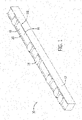
- FIG. 1 is a perspective view of a linear motor system 10 that includes a body 12 configured to support one or more movers 14 that move along a path guided by a guideway 16. While the illustrated linear motor system is straight, in other embodiments, the linear motor system may include curves, sharp horizontal and vertical turns, merge and diverge switching, vertical increases or decreases, and inverted operation, among others.
- the linear motor system may be used in any suitable application, such as moving bottles on an assembly line while they are being filled and capped, moving vials in a laboratory for analysis, moving electronic devices along a production line so that robots can insert components, and sorting objects that arrive from a multiplicity of sources and must be delivered to appropriate locations.
- each of the movers 14 include ferromagnetic materials that interact with a magnetic field move the mover 14 to various locations.
- FIG. 2 is a perspective view of the linear motor system 10 in which the guideway 16 includes coiled wire positioned on or within the base 18 of the guideway 16. While FIG. 2 shows the coiled wire within the base, this is meant as an example and the magnetic field may be produce from coils or magnets within the sides 18.
- the linear motor system 10 may include a control system and a power system. The control system may receive power from the power system. The power system may be electrically coupled to the coiled wire 24, and the control system may control current that flows, from the power system, through the coiled wire 24.
- the control system may produce a magnetic field that moves the mover 14 to a desired location. That is, the magnetic field may apply a force to the ferromagnetic material of the mover 14 to move the mover 14 to the location. Depending on the magnetic field, the ferromagnetic material of the mover 14 may move the mover to a certain location at a certain speed and/or time.
- FIG. 3 is a perspective view of an assembly of a mover 14 of FIG. 1 .
- the mover includes a body structure 26 that forms an enclosure.
- the body structure 26 of the mover 14 moves from the magnetic field applied to ferromagnetic materials within the body structure 26.
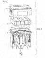
- FIG. 4 is an exploded view of the assembly of the mover 14.
- the mover 14 includes an exploded body structure having a first part 32 and a second part 34 that form an enclosure over a magnetic structure 36 having a magnetic subassembly 38.
- the magnetic structure 36 may include one or more features 38 that align with one or more features 40 of the second part 34 of the body structure to secure the magnetic structure 36 with respect to the body structure.
- the linear motor system 10 moves the magnetic structure 36 to a location that depends on the applied magnetic field from the coiled wire 24. Further, the location of the body structure on the linear motor system 10 may depend on the location of the magnetic structure 36 within the applied magnetic field as well as the location of the body structure with respect to the magnetic structure 36.
- each magnetic subassembly 38 may be differently sized due to inconsistencies in the manufacturing of the magnets of the magnetic subassembly 38.
- the different sizes may result in the magnetic subassembly 38 being positioned inconsistently with respect to the magnetic structure 36. Due to the positioning of the inconsistent positioning of the magnetic structure 36, the features that interact with the features of the body structure may be inconsistently positioned. As such, it is desirable to position the magnetic structure on the magnet subassembly in a manner that centers the magnetic structure on the magnetic field.
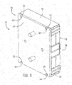
- FIG. 5 is a perspective view of an assembly of part of the mover 14, in accordance with an embodiment.
- the assembly includes the magnetic structure 36 and the magnetic subassembly 38.
- the magnetic subassembly 38 includes one or more magnets 48. While the illustrated embodiment includes five magnets, any suitable number of magnets may be included.
- the magnetic subassembly 38 may form a schach array in which the magnets augment the magnetic field in a first direction and cancel part of the field in another direction.
- the magnets 48 may be coupled together (e.g., via an adhesive, such as an epoxy or glue) to form the magnet subassembly 38. While these are provided as examples of the magnets 48 within the magnetic subassembly 38, any suitable orientation and combination of magnets may be used.
- the magnetic structure 36 includes a multi-piece assembly disposed on at least one side of the magnet subassembly 38.
- the magnetic structure 36 includes a first side plate 50 disposed on a first lateral side of the magnetic subassembly 38 and a second side plate 52 disposed on a second lateral side of the magnetic subassembly 38, opposite the first lateral side.
- Each of the side plates 50 and 52 may be secured to the respective sides of the magnetic subassembly 38 (e.g., via an adhesive, such as an epoxy or glue).
- the first side plate 50 may include a first set of tabs 54
- the second side plate 52 includes a second set of tabs 56.
- the magnetic structure 36 includes a top plate 58.
- the top plate 58 is disposed in a position such that the mover 14 is centered based on the magnetic field.
- the top plate 58 includes a first set of lateral slots 60, and the first set of tabs 54 of the first side plate 50 engage with (e.g., enter into) the respective slots 60 of the top plate 58 when the plates 50, 52, and 58 are positioned around the magnet subassembly 38.
- the top plate 58 includes a second set of lateral slots 64, and the second set of tabs 56 engage with (e.g., enter into) the respective slots 60 of the top plate 58 when the plates 50, 52, and 58 are positioned around the magnet subassembly 38.
- FIG. 6 is an exploded view of the assembly of the part of the mover 14 of FIG. 5 .
- the magnet subassembly 38 is assembled by securing the magnets with one another via an adhesive (e.g., epoxy or glue).
- the magnetic structure 36 is then disposed on the magnet subassembly 38 to create a resultant magnetic field with the magnet subassembly 38.
- the first side plate 50 may be disposed on the first lateral side 66 of the magnetic subassembly 38.
- the first side plate 50 may be secured to the first lateral side 66 via an adhesive (e.g., epoxy or glue).
- the second side plate 52 may be disposed on the second lateral side 68 of the magnetic subassembly 38.
- the second side plate 52 may be secured to the second lateral side 68 via an adhesive (e.g., epoxy or glue).
- FIG. 7 is a top view of the top plate 58 disposed on the magnetic subassembly 38.
- the top plate 58 is disposed on the magnetic subassembly 38 such that the magnetic structure 36 creates with the magnetic subassembly 38 a resultant magnetic field.
- the magnetic structure 36 is centered on a detected center of the resultant magnetic field. That is, a center 72 of the magnetic structure 36 may be positioned in a detected center of the resultant magnetic field.
- a reference feature, such as protrusions 40 or a marking of the center 72, of the magnetic structure 36 may be aligned at a desired location with respect to a detected center of a magnetic field of the magnet subassembly or the resultant magnetic field.
- the first part 32 and the second part 34 of the body structure may be mounted on or with reference to the magnetic structure to position a physical center of the body structure at approximately the detected center of the resultant magnetic field.
- centering the magnetic structure may enable the mover 14 to be located more accurately.
- a physical center of the magnetic structure 36 may be located within +/- 0.25 mm (e.g., 0-.25mm) of the detected center of the resultant magnetic field.
- the slots 60 and 62 of the top plate 58 form gaps 76 and 78 between the respective tabs 54 and 56.
- the top plate 58 may be moved along the direction 74 by sliding the gaps 76 and 78 of top plate 58 between the tabs 54 and 56 to center the magnetic structure 36 in the detected center of the resultant magnetic field. Further, the top plate 58 may be secured to magnet subassembly via an adhesive (e.g., epoxy or glue) to ensure the top plate 58 remains centered in the resultant magnetic field.
- an adhesive e.g., epoxy or glue
- each of the plates may contact the magnet subassembly 38 to eliminate clearances and potential offsets between the magnetic structure 36 and the magnet subassembly 38.
- the slots 60 and 62 of the top plate 58 and the tabs 54 and 56 provide lateral alignment between the side plates 50 and 52 and the top plate 58.
- the multi-piece magnetic structure 36 may allow for pipetting from sample tubes as small 10 millimeters in diameter.
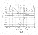
- FIG. 8 is a graph 80 of a magnet array mapping curve 82 having field distances on the X-axis 84 and field strength on the Y-axis 86. While a two dimensional (2D) graph is shown, this is meant to be an example, and a three dimensional (3D) magnet array map may be used.
- the graph 80 includes a centerline 90 indicating a center of the magnetic field produced by the magnet subassembly 38.
- a first reference point 92 and a second reference point 94 may be used to define the centerline 90.
- the center of the magnetic structure 36 and the magnet subassembly 38 may be located between a first distance 96 from the first reference point 92 and a matching second distance 98 from the second reference point 94.
- the detected center may be determined by reference to locations where a magnetic field of the magnet subassembly 38 or the resultant magnetic field changes polarity.
- the first reference point 92 and the second reference point 94 may be determined based on where the magnetic field changes polarity (e.g., zero crossing). Centering the magnetic structure 36 on the centerline 90 of the magnetic field reduces or eliminates machine, assembly, and magnetic tolerances. By reducing or eliminating the variance between the parts and subassemblies, the magnetic structure 36 and the magnet subassembly 38 may have improved positional accuracy.
- the centerline 90 may be a center plane. That is, the magnet subassembly may include a magnetic field center plane and the detected center lies in the magnetic field center plane.
- the magnetic structure 36 may be centered on the centerline 90 of the resultant magnetic field in which the magnetic field is a combination of the magnet subassembly 38 and the magnetic structure.
- a magnetic field may be formed from the magnet subassembly 38.
- the magnetic field of the magnet subassembly 38 may be adjusted due to positioning of the magnetic structure 36 on the magnetic subassembly 38 due to the ferromagnetic materials of the magnetic structure.
- the body structure may be mounted on or with reference to the magnetic structure to position a physical center of the body structure at approximately the detected center of the resultant magnetic field.
- the detected center of the magnetic field may be determined by mapping the magnet subassembly magnetic field prior to assembly of the magnetic subassembly 38 and the magnetic structure 36. That is, the magnetic field may be determined based on the magnet subassembly magnetic field.
Landscapes
- Engineering & Computer Science (AREA)
- Physics & Mathematics (AREA)
- Electromagnetism (AREA)
- Power Engineering (AREA)
- Transportation (AREA)
- Mechanical Engineering (AREA)
- Chemical & Material Sciences (AREA)
- Combustion & Propulsion (AREA)
- Linear Motors (AREA)
Description
- This application claims priority from and the benefit of
U.S. Provisional Application Serial No. 62/362,865, entitled "Transport System Puck Assembly," filed July 15, 2016 - The present disclosure relates generally to transport systems, and more particularly, to an assembly for a mover of the transport system.
- There are many types of transport systems that include movers that move, via rotary motors, linear motors, pneumatics, or the like, along a path of the transport system. For example, linear motors may refer to motors that produce a magnetic field to provide a force to move a mover along a distance of the motor. Linear motors may be used in various applications in which an object is moved, via the mover, from a first location to a second location along the path. For example, the linear motor may include stator windings along the path. Current that flows through the stator windings may drive the mover via one or more magnets within the mover.
- The mover may include various parts and sub-assemblies to move the mover along the path. However, each of the parts and sub-assemblies of the mover may include tolerances that cause the mover to be calibrated in an inconsistent manner. Further, the mover may move to inconsistent locations due to the inconsistencies in the parts and subassemblies.
-
WO 2014/047104 A1 provides in some aspects a transport system comprising a guideway with a plurality of propulsion coils disposed along a region in which one or more vehicles are to be propelled. One or more vehicles are disposed on the guideway, each including a magnetic flux source. The guideway has one or more running surfaces that support the vehicles and along which they roll or slide. -
WO 2014/170414 A2 discloses an electric motor comprising a stator (1) defining a number N, at least equal to two, of pairs of poles and a rotor (2) mounted to pivot in the stator, the motor comprising a number n of electric circuits (10) each defining two windings (11, 12) mounted on poles of the stator, the windings of all the circuits being substantially identical to each other, the number n of electric circuits being greater than the number N of pairs of poles and at least first and second electric circuits (10.1, 10.2) being mounted on a first of the pairs of poles and a third of the electric circuits (10.3) being mounted on a second of the pairs of poles. -
DE 295 20 879 U1 discloses a synchronous linear motor with primary part having a winding and a secondary part including an elongated bearing plate to which the pre-magnetized permanent magnets of brittle and corrosion-prone material, are firmly adhesively secured while maintaining the pole pitch grid. In order to be able to securely bond the pre-magnetized permanent magnets to the secondary part economically and with high precision, it is proposed that spacers (2,3) corresponding to the pole pitch grid of the synchronous linear motor be arranged between pre-magnetized permanent magnets (4). - It is the object of the present invention to provide an improved mover for a linear motor system and an improved method for making a mover for a linear magnet system.
- The object is solved by the subject matter of the independent claims. Preferred embodiments of the present invention are defined by the dependent claims.
- The claims define the scope of the invention. Embodiments of the invention as well as further aspects and embodiments useful for understanding the invention are described in the following.
- A summary of certain embodiments disclosed herein is set forth below. It should be understood that these aspects are presented merely to provide the reader with a brief summary of these certain embodiments and that these aspects are not intended to limit the scope of this disclosure. Indeed, this disclosure may encompass a variety of aspects that may not be set forth below.
- In a first embodiment, a mover for a linear motor system includes a magnet subassembly, a magnetic structure disposed on at least one side of the magnet subassembly and creating with the magnetic subassembly a resultant magnetic field, the magnetic structure being centered on a detected center of the resultant magnetic field, and a body structure mounted on or with reference to the magnetic structure to position a physical center of the body structure at approximately the detected center of the resultant magnetic field.
- In a second embodiment, a method for making a mover for a linear magnet system, the method includes assembling a magnet subassembly, disposing a magnetic structure on at least one side of the magnet subassembly to create a resultant magnetic field with the magnet subassembly, and centering the magnetic structure on a detected center of a magnetic field of the magnet subassembly or the resultant magnetic field.
- In a third embodiment, a method for making a mover for a linear magnet system includes assembling a magnet subassembly, disposing a magnetic structure on at least one side of the magnet subassembly to create a resultant magnetic field with the magnet subassembly, aligning a reference feature of the magnetic structure at a desired location with respect to a detected center of a magnetic field of the magnet subassembly or the resultant magnetic field, and securing the magnetic structure to the magnet subassembly.
- These and other features, aspects, and advantages of the present invention will become better understood when the following detailed description is read with reference to the accompanying drawings in which like characters represent like parts throughout the drawings, wherein:
-
FIG. 1 is a perspective view of an embodiment of a linear motor system that includes a mover that moves along a path of the linear motor system; -
FIG. 2 is a cut away perspective view of an embodiment of the linear motor system ofFIG. 1 moving along the path via coiled wire of the linear motor system; -
FIG. 3 is a perspective view of an embodiment of the mover ofFIG. 1 having a body structure; -
FIG. 4 is an exploded perspective view of an embodiment of the mover ofFIG. 3 with the body structure exploded to show the magnetic structure and magnetic subassembly; -
FIG. 5 is a perspective view of an embodiment of the magnetic structure and magnetic subassembly ofFIG. 4 ; -
FIG. 6 is an exploded perspective view of an embodiment of the magnetic structure and the magnetic subassembly ofFIG. 4 ; -
FIG. 7 is a top view of an embodiment of a top plate of the magnetic structure ofFIG. 4 ; and -
FIG. 8 is a graph of an embodiment of a mapping curve of the magnetic subassembly and magnetic structure ofFIG. 4 . - Embodiments of the present disclosure relate to movers, referred to as pucks, of a linear motor system. The movers may include various parts and sub-assemblies that move the mover to a location due to the interaction between ferromagnetic materials of the mover and the magnetic field of the linear motor system. For example, a magnetic subassembly of magnets may be coupled to one another to form a halbach array of magnets in which a magnetic field is reduced in one direction and increased in another direction. Each of the assemblies may be inconsistent from one another due to different mechanical and magnetic tolerances of the parts and subassemblies. For example, different sized parts may be used that vary from mover to mover. Because of the inconsistent assemblies, various movers may move with respect to the magnetic field to different locations resulting in reduced accuracy of the linear motor system.
- To compensate for the inconsistencies between various parts, the mover may be made using a multi-piece magnetic structure that is coupled to the magnet subassembly (e.g., via an adhesive). The magnetic structure may include a top plate that is physically centered on a detected center of a magnetic field. By centering the magnetic structure of the mover based on a detected center of the magnetic field, each mover may move to locations consistent with one another due to the applied magnetic field of the linear motor system.
- Turning now to the drawings,
FIG. 1 is a perspective view of alinear motor system 10 that includes abody 12 configured to support one ormore movers 14 that move along a path guided by aguideway 16. While the illustrated linear motor system is straight, in other embodiments, the linear motor system may include curves, sharp horizontal and vertical turns, merge and diverge switching, vertical increases or decreases, and inverted operation, among others. The linear motor system may be used in any suitable application, such as moving bottles on an assembly line while they are being filled and capped, moving vials in a laboratory for analysis, moving electronic devices along a production line so that robots can insert components, and sorting objects that arrive from a multiplicity of sources and must be delivered to appropriate locations. As described in detail below, each of themovers 14 include ferromagnetic materials that interact with a magnetic field move themover 14 to various locations. - The
guideway 16 may guide themover 14 along a path from location to location via the magnetic field.FIG. 2 is a perspective view of thelinear motor system 10 in which theguideway 16 includes coiled wire positioned on or within thebase 18 of theguideway 16. WhileFIG. 2 shows the coiled wire within the base, this is meant as an example and the magnetic field may be produce from coils or magnets within thesides 18. Thelinear motor system 10 may include a control system and a power system. The control system may receive power from the power system. The power system may be electrically coupled to the coiledwire 24, and the control system may control current that flows, from the power system, through thecoiled wire 24. By controlling the current that flows through the coiledwire 24, the control system may produce a magnetic field that moves themover 14 to a desired location. That is, the magnetic field may apply a force to the ferromagnetic material of themover 14 to move themover 14 to the location. Depending on the magnetic field, the ferromagnetic material of themover 14 may move the mover to a certain location at a certain speed and/or time. -
FIG. 3 is a perspective view of an assembly of amover 14 ofFIG. 1 . The mover includes abody structure 26 that forms an enclosure. Thebody structure 26 of themover 14 moves from the magnetic field applied to ferromagnetic materials within thebody structure 26.FIG. 4 is an exploded view of the assembly of themover 14. In the illustrated embodiment, themover 14 includes an exploded body structure having afirst part 32 and asecond part 34 that form an enclosure over amagnetic structure 36 having amagnetic subassembly 38. Themagnetic structure 36 may include one ormore features 38 that align with one ormore features 40 of thesecond part 34 of the body structure to secure themagnetic structure 36 with respect to the body structure. That is, thelinear motor system 10 moves themagnetic structure 36 to a location that depends on the applied magnetic field from the coiledwire 24. Further, the location of the body structure on thelinear motor system 10 may depend on the location of themagnetic structure 36 within the applied magnetic field as well as the location of the body structure with respect to themagnetic structure 36. - However, due to the inconsistencies of mechanical and magnetic tolerances in parts and subassemblies, the magnetic field produced by the
linear motor system 10 may move each of themovers 14 to different locations. For example, eachmagnetic subassembly 38 may be differently sized due to inconsistencies in the manufacturing of the magnets of themagnetic subassembly 38. The different sizes may result in themagnetic subassembly 38 being positioned inconsistently with respect to themagnetic structure 36. Due to the positioning of the inconsistent positioning of themagnetic structure 36, the features that interact with the features of the body structure may be inconsistently positioned. As such, it is desirable to position the magnetic structure on the magnet subassembly in a manner that centers the magnetic structure on the magnetic field. -
FIG. 5 is a perspective view of an assembly of part of themover 14, in accordance with an embodiment. The assembly includes themagnetic structure 36 and themagnetic subassembly 38. Themagnetic subassembly 38 includes one ormore magnets 48. While the illustrated embodiment includes five magnets, any suitable number of magnets may be included. In some embodiments, themagnetic subassembly 38 may form a halbach array in which the magnets augment the magnetic field in a first direction and cancel part of the field in another direction. Further, themagnets 48 may be coupled together (e.g., via an adhesive, such as an epoxy or glue) to form themagnet subassembly 38. While these are provided as examples of themagnets 48 within themagnetic subassembly 38, any suitable orientation and combination of magnets may be used. - In the illustrated embodiment, the
magnetic structure 36 includes a multi-piece assembly disposed on at least one side of themagnet subassembly 38. Themagnetic structure 36 includes afirst side plate 50 disposed on a first lateral side of themagnetic subassembly 38 and asecond side plate 52 disposed on a second lateral side of themagnetic subassembly 38, opposite the first lateral side. Each of theside plates first side plate 50 may include a first set oftabs 54, and thesecond side plate 52 includes a second set oftabs 56. - In the illustrated embodiment, the
magnetic structure 36 includes atop plate 58. As discussed below, thetop plate 58 is disposed in a position such that themover 14 is centered based on the magnetic field. Thetop plate 58 includes a first set oflateral slots 60, and the first set oftabs 54 of thefirst side plate 50 engage with (e.g., enter into) therespective slots 60 of thetop plate 58 when theplates magnet subassembly 38. Thetop plate 58 includes a second set oflateral slots 64, and the second set oftabs 56 engage with (e.g., enter into) therespective slots 60 of thetop plate 58 when theplates magnet subassembly 38. -
FIG. 6 is an exploded view of the assembly of the part of themover 14 ofFIG. 5 . To make themover 14 for thelinear motion system 10, themagnet subassembly 38 is assembled by securing the magnets with one another via an adhesive (e.g., epoxy or glue). Themagnetic structure 36 is then disposed on themagnet subassembly 38 to create a resultant magnetic field with themagnet subassembly 38. For example, thefirst side plate 50 may be disposed on the firstlateral side 66 of themagnetic subassembly 38. Thefirst side plate 50 may be secured to the firstlateral side 66 via an adhesive (e.g., epoxy or glue). Similarly, thesecond side plate 52 may be disposed on the secondlateral side 68 of themagnetic subassembly 38. Thesecond side plate 52 may be secured to the secondlateral side 68 via an adhesive (e.g., epoxy or glue). -
FIG. 7 is a top view of thetop plate 58 disposed on themagnetic subassembly 38. Thetop plate 58 is disposed on themagnetic subassembly 38 such that themagnetic structure 36 creates with the magnetic subassembly 38 a resultant magnetic field. Themagnetic structure 36 is centered on a detected center of the resultant magnetic field. That is, acenter 72 of themagnetic structure 36 may be positioned in a detected center of the resultant magnetic field. For example, a reference feature, such asprotrusions 40 or a marking of thecenter 72, of themagnetic structure 36 may be aligned at a desired location with respect to a detected center of a magnetic field of the magnet subassembly or the resultant magnetic field. - By centering the
magnetic structure 36 on the detected center of the resultant magnetic field, thefirst part 32 and thesecond part 34 of the body structure may be mounted on or with reference to the magnetic structure to position a physical center of the body structure at approximately the detected center of the resultant magnetic field. As such, centering the magnetic structure may enable themover 14 to be located more accurately. For example, a physical center of themagnetic structure 36 may be located within +/- 0.25 mm (e.g., 0-.25mm) of the detected center of the resultant magnetic field. - The
slots top plate 58form gaps respective tabs top plate 58 may be moved along thedirection 74 by sliding thegaps top plate 58 between thetabs magnetic structure 36 in the detected center of the resultant magnetic field. Further, thetop plate 58 may be secured to magnet subassembly via an adhesive (e.g., epoxy or glue) to ensure thetop plate 58 remains centered in the resultant magnetic field. By having a multi-piecemagnetic structure 36, each of the plates (e.g.,first side plate 50,second side plate 52, and top plate 58) may contact themagnet subassembly 38 to eliminate clearances and potential offsets between themagnetic structure 36 and themagnet subassembly 38. Theslots top plate 58 and thetabs side plates top plate 58. For example, due to the positioning of thetop plate 58, the multi-piecemagnetic structure 36 may allow for pipetting from sample tubes as small 10 millimeters in diameter. -
FIG. 8 is agraph 80 of a magnetarray mapping curve 82 having field distances on theX-axis 84 and field strength on the Y-axis 86. While a two dimensional (2D) graph is shown, this is meant to be an example, and a three dimensional (3D) magnet array map may be used. In the illustrated embodiment, thegraph 80 includes acenterline 90 indicating a center of the magnetic field produced by themagnet subassembly 38. To center thetop plate 58 of themagnetic structure 36 on themagnet subassembly 38, afirst reference point 92 and asecond reference point 94 may be used to define thecenterline 90. For example, the center of themagnetic structure 36 and themagnet subassembly 38 may be located between afirst distance 96 from thefirst reference point 92 and a matchingsecond distance 98 from thesecond reference point 94. The detected center may be determined by reference to locations where a magnetic field of themagnet subassembly 38 or the resultant magnetic field changes polarity. For example, thefirst reference point 92 and thesecond reference point 94 may be determined based on where the magnetic field changes polarity (e.g., zero crossing). Centering themagnetic structure 36 on thecenterline 90 of the magnetic field reduces or eliminates machine, assembly, and magnetic tolerances. By reducing or eliminating the variance between the parts and subassemblies, themagnetic structure 36 and themagnet subassembly 38 may have improved positional accuracy. - Further, in three dimensional embodiments, the
centerline 90 may be a center plane. That is, the magnet subassembly may include a magnetic field center plane and the detected center lies in the magnetic field center plane. - The
magnetic structure 36 may be centered on thecenterline 90 of the resultant magnetic field in which the magnetic field is a combination of themagnet subassembly 38 and the magnetic structure. For example, a magnetic field may be formed from themagnet subassembly 38. The magnetic field of themagnet subassembly 38 may be adjusted due to positioning of themagnetic structure 36 on themagnetic subassembly 38 due to the ferromagnetic materials of the magnetic structure. By adjusting themagnet subassembly 38 to be centered on the resultant magnetic field, the body structure may be mounted on or with reference to the magnetic structure to position a physical center of the body structure at approximately the detected center of the resultant magnetic field. In some embodiments, the detected center of the magnetic field may be determined by mapping the magnet subassembly magnetic field prior to assembly of themagnetic subassembly 38 and themagnetic structure 36. That is, the magnetic field may be determined based on the magnet subassembly magnetic field. - While only certain features of the invention have been illustrated and described herein, many modifications and changes will occur to those skilled in the art. It is, therefore, to be understood that the scope of the invention is defined by the appended claims.
Claims (8)
- A mover (14) for a linear motor system, comprising:a magnet subassembly (38);a magnetic structure (36) disposed on at least one side of the magnet subassembly (38) and creating with the magnetic subassembly (38) a resultant magnetic field, the magnetic structure (36) being centered on a center of a magnetic field of the magnet subassembly (38); anda body structure (26) mounted on or with reference to the magnetic structure (36) to position a physical center of the body structure (26) at approximately the detected center (90) of the resultant magnetic field of the magnet subassembly (38);wherein the magnetic structure (36) comprises a top plate (58) and two lateral plates (50, 52), the top plate (58) comprises lateral slots (60, 62), and each of the lateral plates (50, 52) comprise a tab (54, 56) that enters into a respective slot (60, 62) of the top plate (58) when the plates (54, 56, 58) are positioned around the magnet subassembly (38);characterized in thatgaps (76, 78) are formed between each tab (54, 56) and the respective slot (60, 62), the gaps (76, 78) being configured to enable lateral movement of the top plate (58) to center the magnetic structure (36) on the detected center (90) of the resultant magnetic field of the magnet subassembly (38).
- The mover of claim 1, wherein the physical center of the body structure (26) is located within +/- 0.25 mm of the center (90) of the resultant magnetic field.
- The mover of one of claims 1 to 2, wherein the magnet subassembly comprises a magnetic field center plane, and wherein the center of the resultant magnetic field lies in the magnetic field center plane.
- A method for making a mover (14) for a linear magnet system, the method comprising:assembling a magnet subassembly (38);disposing a magnetic structure (36) on at least one side of the magnet subassembly (38) to create a resultant magnetic field with the magnet subassembly (38);centering the magnetic structure (36) on a center of a magnetic field of the magnet subassembly (38); andmounting a body structure (26) on or with reference to the magnetic structure (36) to position a physical center of the body structure (26) at approximately the detected center (90) of the resultant magnetic field of the magnet subassembly (38);wherein the magnetic structure (36) comprises a top plate (58) and two lateral plates (50, 52), the top plate (58) comprises lateral slots (60, 62), and each of the lateral plates (50, 52) comprise a tab (54, 56) that enters into a respective slot (60, 62) of the top plate (58) when the plates (50, 52, 58) are positioned around the magnet subassembly (38),characterized in thatgaps (76, 78) are formed between each tab (54, 56) and the respective slot (60, 62), and wherein the magnetic structure (36) is centered on the detected center (90) of the resultant magnetic field of the magnet subassembly (38) by lateral movement of the top plate (58), the lateral movement being enabled by the gaps (76, 78).
- The method of one of claim 4, wherein the magnetic structure (36) is adhesively secured to the magnet subassembly (38).
- The method of claim 4, wherein the step of centering the magnetic structure (36) comprises:aligning a reference feature (40, 72) of the magnetic structure (36) at a desired location with respect to the detected center (90) of the resultant magnetic field of the magnet subassembly (38); andthe method further comprises securing the magnetic structure (36) to the magnet subassembly (38).
- The method of claim 6, comprising positioning the body structure (26) to the magnetic structure (36) based upon the resultant magnetic field of the magnet subassembly (38).
- The method of claim 6, wherein the center of the magnetic field of the magnet subassembly (38) is determined by mapping of the magnet subassembly magnetic field prior to assembly of the magnet subassembly (38) and the magnetic structure (36).
Applications Claiming Priority (2)
| Application Number | Priority Date | Filing Date | Title |
|---|---|---|---|
| US201662362865P | 2016-07-15 | 2016-07-15 | |
| US15/631,490 US10686355B2 (en) | 2016-07-15 | 2017-06-23 | Transport system puck assembly |
Publications (3)
| Publication Number | Publication Date |
|---|---|
| EP3285379A2 EP3285379A2 (en) | 2018-02-21 |
| EP3285379A3 EP3285379A3 (en) | 2018-07-04 |
| EP3285379B1 true EP3285379B1 (en) | 2022-05-25 |
Family
ID=60941412
Family Applications (1)
| Application Number | Title | Priority Date | Filing Date |
|---|---|---|---|
| EP17181637.4A Active EP3285379B1 (en) | 2016-07-15 | 2017-07-17 | Mover for a linear motor system |
Country Status (3)
| Country | Link |
|---|---|
| US (1) | US10686355B2 (en) |
| EP (1) | EP3285379B1 (en) |
| CN (1) | CN107623427B (en) |
Families Citing this family (1)
| Publication number | Priority date | Publication date | Assignee | Title |
|---|---|---|---|---|
| EP4535630A1 (en) * | 2023-10-03 | 2025-04-09 | ABB Schweiz AG | Automation system in the form of a planar motor |
Family Cites Families (11)
| Publication number | Priority date | Publication date | Assignee | Title |
|---|---|---|---|---|
| DE29520879U1 (en) | 1995-02-03 | 1996-04-11 | Krauss-Maffei AG, 80997 München | Synchronous linear motor |
| JP3470293B2 (en) | 2001-12-17 | 2003-11-25 | 山崎 恒彦 | Linear motor |
| WO2004086595A1 (en) * | 2003-03-24 | 2004-10-07 | Technische Universität Berlin | Gliding field linear motor |
| CN1799180A (en) | 2003-06-06 | 2006-07-05 | Bei传感器及系统有限公司 | Ironcore linear brushless DC motor with reduced detent force |
| US7378765B2 (en) * | 2004-08-09 | 2008-05-27 | Oriental Motor Co., Ltd. | Cylinder-type linear motor and moving part thereof |
| DE102006049588B4 (en) | 2006-02-03 | 2020-08-13 | Sew-Eurodrive Gmbh & Co Kg | Transport system |
| KR20160125533A (en) | 2009-01-23 | 2016-10-31 | 마그네모션, 인코포레이티드 | Improved transport system powered by short block linear synchronous motors and switching mechanism |
| DE102010000582A1 (en) * | 2010-02-26 | 2011-09-01 | Karl Storz Gmbh & Co. Kg | Linear motor with permanent magnetic latching |
| WO2014047104A1 (en) | 2012-09-20 | 2014-03-27 | Magnemotion, Inc. | Short block linear synchronous motors and switching mechanisms |
| FR3004864B1 (en) | 2013-04-18 | 2015-04-24 | Sagem Defense Securite | ELECTRIC MOTOR WITH REDUNDANT ELECTRIC CIRCUITS |
| CN204205909U (en) | 2014-09-28 | 2015-03-11 | 浙江理工大学 | A kind of magnetic suspension multiple degrees of freedom permanent magnetic synchronous plane electromotor motor |
-
2017
- 2017-06-23 US US15/631,490 patent/US10686355B2/en active Active
- 2017-07-11 CN CN201710561032.2A patent/CN107623427B/en active Active
- 2017-07-17 EP EP17181637.4A patent/EP3285379B1/en active Active
Also Published As
| Publication number | Publication date |
|---|---|
| CN107623427A (en) | 2018-01-23 |
| US20180019653A1 (en) | 2018-01-18 |
| US10686355B2 (en) | 2020-06-16 |
| EP3285379A3 (en) | 2018-07-04 |
| EP3285379A2 (en) | 2018-02-21 |
| CN107623427B (en) | 2020-07-14 |
Similar Documents
| Publication | Publication Date | Title |
|---|---|---|
| US20100327669A1 (en) | Multi-degree-of-freedom actuator and stage device | |
| KR101497216B1 (en) | Linear motor | |
| JP2002064968A (en) | Slide device with moving coil type linear motor | |
| JP2003158866A (en) | Forcer and three-phase linear motor system | |
| US4835424A (en) | Platen laminated in mutually perpendicular direction for use with linear motors and the like | |
| CN204835887U (en) | Nose bar formula does not have iron core linear motor motion module | |
| KR102069990B1 (en) | Sheet Separation Apparatus, Sheet Separation Method, and Manufacturing Method of Sheet Shape Secondary Battery | |
| HK54388A (en) | Electrodynamic device for translating an objective | |
| US20160111948A1 (en) | Fine element magnet array | |
| JPH08140U (en) | Slide displacement device | |
| US20150054357A1 (en) | Armature of coreless linear motor and coreless linear motor using the same | |
| US20240283345A1 (en) | Double-sided linear motor | |
| US10686355B2 (en) | Transport system puck assembly | |
| CN108011489B (en) | Multi-unit micro-stroke voice coil linear motor | |
| US7312541B2 (en) | Actuator and bonding apparatus | |
| JPH07170712A (en) | Actuator | |
| KR20210148401A (en) | Linear motor and wire bonding machine including same | |
| US20030141768A1 (en) | Linear motor | |
| KR101970943B1 (en) | Slit linear stage | |
| JP2024117159A (en) | Constant force generator and device equipped with same | |
| KR101370230B1 (en) | Linear motor | |
| JP2006054973A (en) | Linear motor for machine tools | |
| KR20010044157A (en) | Brushless, coil core type linear motor and linear motion apparatus having the same | |
| US20240006973A1 (en) | Permanent field magnet and linear motor | |
| CN103460575B (en) | linear motor |
Legal Events
| Date | Code | Title | Description |
|---|---|---|---|
| PUAI | Public reference made under article 153(3) epc to a published international application that has entered the european phase |
Free format text: ORIGINAL CODE: 0009012 |
|
| STAA | Information on the status of an ep patent application or granted ep patent |
Free format text: STATUS: THE APPLICATION HAS BEEN PUBLISHED |
|
| AK | Designated contracting states |
Kind code of ref document: A2 Designated state(s): AL AT BE BG CH CY CZ DE DK EE ES FI FR GB GR HR HU IE IS IT LI LT LU LV MC MK MT NL NO PL PT RO RS SE SI SK SM TR |
|
| AX | Request for extension of the european patent |
Extension state: BA ME |
|
| PUAL | Search report despatched |
Free format text: ORIGINAL CODE: 0009013 |
|
| AK | Designated contracting states |
Kind code of ref document: A3 Designated state(s): AL AT BE BG CH CY CZ DE DK EE ES FI FR GB GR HR HU IE IS IT LI LT LU LV MC MK MT NL NO PL PT RO RS SE SI SK SM TR |
|
| AX | Request for extension of the european patent |
Extension state: BA ME |
|
| RIC1 | Information provided on ipc code assigned before grant |
Ipc: B60L 13/03 20060101ALI20180529BHEP Ipc: H02K 41/03 20060101AFI20180529BHEP Ipc: B60L 13/10 20060101ALI20180529BHEP |
|
| STAA | Information on the status of an ep patent application or granted ep patent |
Free format text: STATUS: REQUEST FOR EXAMINATION WAS MADE |
|
| 17P | Request for examination filed |
Effective date: 20181211 |
|
| RBV | Designated contracting states (corrected) |
Designated state(s): AL AT BE BG CH CY CZ DE DK EE ES FI FR GB GR HR HU IE IS IT LI LT LU LV MC MK MT NL NO PL PT RO RS SE SI SK SM TR |
|
| STAA | Information on the status of an ep patent application or granted ep patent |
Free format text: STATUS: EXAMINATION IS IN PROGRESS |
|
| 17Q | First examination report despatched |
Effective date: 20200730 |
|
| RAP1 | Party data changed (applicant data changed or rights of an application transferred) |
Owner name: MAGNEMOTION, INC. Owner name: SCHLATTER, DAVID Owner name: DEVANEY, THOMAS Owner name: YAGCI, BARIS Owner name: MALYAROV, ILYA |
|
| GRAP | Despatch of communication of intention to grant a patent |
Free format text: ORIGINAL CODE: EPIDOSNIGR1 |
|
| STAA | Information on the status of an ep patent application or granted ep patent |
Free format text: STATUS: GRANT OF PATENT IS INTENDED |
|
| INTG | Intention to grant announced |
Effective date: 20220110 |
|
| GRAS | Grant fee paid |
Free format text: ORIGINAL CODE: EPIDOSNIGR3 |
|
| GRAA | (expected) grant |
Free format text: ORIGINAL CODE: 0009210 |
|
| STAA | Information on the status of an ep patent application or granted ep patent |
Free format text: STATUS: THE PATENT HAS BEEN GRANTED |
|
| AK | Designated contracting states |
Kind code of ref document: B1 Designated state(s): AL AT BE BG CH CY CZ DE DK EE ES FI FR GB GR HR HU IE IS IT LI LT LU LV MC MK MT NL NO PL PT RO RS SE SI SK SM TR |
|
| REG | Reference to a national code |
Ref country code: GB Ref legal event code: FG4D |
|
| REG | Reference to a national code |
Ref country code: CH Ref legal event code: EP |
|
| REG | Reference to a national code |
Ref country code: DE Ref legal event code: R096 Ref document number: 602017057780 Country of ref document: DE |
|
| REG | Reference to a national code |
Ref country code: AT Ref legal event code: REF Ref document number: 1494638 Country of ref document: AT Kind code of ref document: T Effective date: 20220615 |
|
| REG | Reference to a national code |
Ref country code: IE Ref legal event code: FG4D |
|
| REG | Reference to a national code |
Ref country code: LT Ref legal event code: MG9D |
|
| REG | Reference to a national code |
Ref country code: NL Ref legal event code: MP Effective date: 20220525 |
|
| REG | Reference to a national code |
Ref country code: AT Ref legal event code: MK05 Ref document number: 1494638 Country of ref document: AT Kind code of ref document: T Effective date: 20220525 |
|
| PG25 | Lapsed in a contracting state [announced via postgrant information from national office to epo] |
Ref country code: SE Free format text: LAPSE BECAUSE OF FAILURE TO SUBMIT A TRANSLATION OF THE DESCRIPTION OR TO PAY THE FEE WITHIN THE PRESCRIBED TIME-LIMIT Effective date: 20220525 Ref country code: PT Free format text: LAPSE BECAUSE OF FAILURE TO SUBMIT A TRANSLATION OF THE DESCRIPTION OR TO PAY THE FEE WITHIN THE PRESCRIBED TIME-LIMIT Effective date: 20220926 Ref country code: NO Free format text: LAPSE BECAUSE OF FAILURE TO SUBMIT A TRANSLATION OF THE DESCRIPTION OR TO PAY THE FEE WITHIN THE PRESCRIBED TIME-LIMIT Effective date: 20220825 Ref country code: NL Free format text: LAPSE BECAUSE OF FAILURE TO SUBMIT A TRANSLATION OF THE DESCRIPTION OR TO PAY THE FEE WITHIN THE PRESCRIBED TIME-LIMIT Effective date: 20220525 Ref country code: LT Free format text: LAPSE BECAUSE OF FAILURE TO SUBMIT A TRANSLATION OF THE DESCRIPTION OR TO PAY THE FEE WITHIN THE PRESCRIBED TIME-LIMIT Effective date: 20220525 Ref country code: HR Free format text: LAPSE BECAUSE OF FAILURE TO SUBMIT A TRANSLATION OF THE DESCRIPTION OR TO PAY THE FEE WITHIN THE PRESCRIBED TIME-LIMIT Effective date: 20220525 Ref country code: GR Free format text: LAPSE BECAUSE OF FAILURE TO SUBMIT A TRANSLATION OF THE DESCRIPTION OR TO PAY THE FEE WITHIN THE PRESCRIBED TIME-LIMIT Effective date: 20220826 Ref country code: FI Free format text: LAPSE BECAUSE OF FAILURE TO SUBMIT A TRANSLATION OF THE DESCRIPTION OR TO PAY THE FEE WITHIN THE PRESCRIBED TIME-LIMIT Effective date: 20220525 Ref country code: ES Free format text: LAPSE BECAUSE OF FAILURE TO SUBMIT A TRANSLATION OF THE DESCRIPTION OR TO PAY THE FEE WITHIN THE PRESCRIBED TIME-LIMIT Effective date: 20220525 Ref country code: BG Free format text: LAPSE BECAUSE OF FAILURE TO SUBMIT A TRANSLATION OF THE DESCRIPTION OR TO PAY THE FEE WITHIN THE PRESCRIBED TIME-LIMIT Effective date: 20220825 Ref country code: AT Free format text: LAPSE BECAUSE OF FAILURE TO SUBMIT A TRANSLATION OF THE DESCRIPTION OR TO PAY THE FEE WITHIN THE PRESCRIBED TIME-LIMIT Effective date: 20220525 |
|
| PG25 | Lapsed in a contracting state [announced via postgrant information from national office to epo] |
Ref country code: RS Free format text: LAPSE BECAUSE OF FAILURE TO SUBMIT A TRANSLATION OF THE DESCRIPTION OR TO PAY THE FEE WITHIN THE PRESCRIBED TIME-LIMIT Effective date: 20220525 Ref country code: PL Free format text: LAPSE BECAUSE OF FAILURE TO SUBMIT A TRANSLATION OF THE DESCRIPTION OR TO PAY THE FEE WITHIN THE PRESCRIBED TIME-LIMIT Effective date: 20220525 Ref country code: LV Free format text: LAPSE BECAUSE OF FAILURE TO SUBMIT A TRANSLATION OF THE DESCRIPTION OR TO PAY THE FEE WITHIN THE PRESCRIBED TIME-LIMIT Effective date: 20220525 Ref country code: IS Free format text: LAPSE BECAUSE OF FAILURE TO SUBMIT A TRANSLATION OF THE DESCRIPTION OR TO PAY THE FEE WITHIN THE PRESCRIBED TIME-LIMIT Effective date: 20220925 |
|
| PG25 | Lapsed in a contracting state [announced via postgrant information from national office to epo] |
Ref country code: SM Free format text: LAPSE BECAUSE OF FAILURE TO SUBMIT A TRANSLATION OF THE DESCRIPTION OR TO PAY THE FEE WITHIN THE PRESCRIBED TIME-LIMIT Effective date: 20220525 Ref country code: SK Free format text: LAPSE BECAUSE OF FAILURE TO SUBMIT A TRANSLATION OF THE DESCRIPTION OR TO PAY THE FEE WITHIN THE PRESCRIBED TIME-LIMIT Effective date: 20220525 Ref country code: RO Free format text: LAPSE BECAUSE OF FAILURE TO SUBMIT A TRANSLATION OF THE DESCRIPTION OR TO PAY THE FEE WITHIN THE PRESCRIBED TIME-LIMIT Effective date: 20220525 Ref country code: EE Free format text: LAPSE BECAUSE OF FAILURE TO SUBMIT A TRANSLATION OF THE DESCRIPTION OR TO PAY THE FEE WITHIN THE PRESCRIBED TIME-LIMIT Effective date: 20220525 Ref country code: DK Free format text: LAPSE BECAUSE OF FAILURE TO SUBMIT A TRANSLATION OF THE DESCRIPTION OR TO PAY THE FEE WITHIN THE PRESCRIBED TIME-LIMIT Effective date: 20220525 Ref country code: CZ Free format text: LAPSE BECAUSE OF FAILURE TO SUBMIT A TRANSLATION OF THE DESCRIPTION OR TO PAY THE FEE WITHIN THE PRESCRIBED TIME-LIMIT Effective date: 20220525 |
|
| PG25 | Lapsed in a contracting state [announced via postgrant information from national office to epo] |
Ref country code: MC Free format text: LAPSE BECAUSE OF FAILURE TO SUBMIT A TRANSLATION OF THE DESCRIPTION OR TO PAY THE FEE WITHIN THE PRESCRIBED TIME-LIMIT Effective date: 20220525 |
|
| REG | Reference to a national code |
Ref country code: DE Ref legal event code: R097 Ref document number: 602017057780 Country of ref document: DE Ref country code: CH Ref legal event code: PL |
|
| REG | Reference to a national code |
Ref country code: BE Ref legal event code: MM Effective date: 20220731 |
|
| PG25 | Lapsed in a contracting state [announced via postgrant information from national office to epo] |
Ref country code: AL Free format text: LAPSE BECAUSE OF FAILURE TO SUBMIT A TRANSLATION OF THE DESCRIPTION OR TO PAY THE FEE WITHIN THE PRESCRIBED TIME-LIMIT Effective date: 20220525 |
|
| PLBE | No opposition filed within time limit |
Free format text: ORIGINAL CODE: 0009261 |
|
| STAA | Information on the status of an ep patent application or granted ep patent |
Free format text: STATUS: NO OPPOSITION FILED WITHIN TIME LIMIT |
|
| PG25 | Lapsed in a contracting state [announced via postgrant information from national office to epo] |
Ref country code: LU Free format text: LAPSE BECAUSE OF NON-PAYMENT OF DUE FEES Effective date: 20220717 Ref country code: LI Free format text: LAPSE BECAUSE OF NON-PAYMENT OF DUE FEES Effective date: 20220731 Ref country code: CH Free format text: LAPSE BECAUSE OF NON-PAYMENT OF DUE FEES Effective date: 20220731 |
|
| 26N | No opposition filed |
Effective date: 20230228 |
|
| PG25 | Lapsed in a contracting state [announced via postgrant information from national office to epo] |
Ref country code: SI Free format text: LAPSE BECAUSE OF FAILURE TO SUBMIT A TRANSLATION OF THE DESCRIPTION OR TO PAY THE FEE WITHIN THE PRESCRIBED TIME-LIMIT Effective date: 20220525 Ref country code: BE Free format text: LAPSE BECAUSE OF NON-PAYMENT OF DUE FEES Effective date: 20220731 |
|
| P01 | Opt-out of the competence of the unified patent court (upc) registered |
Effective date: 20230404 |
|
| PG25 | Lapsed in a contracting state [announced via postgrant information from national office to epo] |
Ref country code: IE Free format text: LAPSE BECAUSE OF NON-PAYMENT OF DUE FEES Effective date: 20220717 |
|
| PG25 | Lapsed in a contracting state [announced via postgrant information from national office to epo] |
Ref country code: IT Free format text: LAPSE BECAUSE OF FAILURE TO SUBMIT A TRANSLATION OF THE DESCRIPTION OR TO PAY THE FEE WITHIN THE PRESCRIBED TIME-LIMIT Effective date: 20220525 |
|
| PG25 | Lapsed in a contracting state [announced via postgrant information from national office to epo] |
Ref country code: HU Free format text: LAPSE BECAUSE OF FAILURE TO SUBMIT A TRANSLATION OF THE DESCRIPTION OR TO PAY THE FEE WITHIN THE PRESCRIBED TIME-LIMIT; INVALID AB INITIO Effective date: 20170717 |
|
| PG25 | Lapsed in a contracting state [announced via postgrant information from national office to epo] |
Ref country code: MK Free format text: LAPSE BECAUSE OF FAILURE TO SUBMIT A TRANSLATION OF THE DESCRIPTION OR TO PAY THE FEE WITHIN THE PRESCRIBED TIME-LIMIT Effective date: 20220525 Ref country code: CY Free format text: LAPSE BECAUSE OF FAILURE TO SUBMIT A TRANSLATION OF THE DESCRIPTION OR TO PAY THE FEE WITHIN THE PRESCRIBED TIME-LIMIT Effective date: 20220525 |
|
| PG25 | Lapsed in a contracting state [announced via postgrant information from national office to epo] |
Ref country code: MT Free format text: LAPSE BECAUSE OF FAILURE TO SUBMIT A TRANSLATION OF THE DESCRIPTION OR TO PAY THE FEE WITHIN THE PRESCRIBED TIME-LIMIT Effective date: 20220525 |
|
| PG25 | Lapsed in a contracting state [announced via postgrant information from national office to epo] |
Ref country code: BG Free format text: LAPSE BECAUSE OF FAILURE TO SUBMIT A TRANSLATION OF THE DESCRIPTION OR TO PAY THE FEE WITHIN THE PRESCRIBED TIME-LIMIT Effective date: 20220525 |
|
| PG25 | Lapsed in a contracting state [announced via postgrant information from national office to epo] |
Ref country code: BG Free format text: LAPSE BECAUSE OF FAILURE TO SUBMIT A TRANSLATION OF THE DESCRIPTION OR TO PAY THE FEE WITHIN THE PRESCRIBED TIME-LIMIT Effective date: 20220525 |
|
| PGFP | Annual fee paid to national office [announced via postgrant information from national office to epo] |
Ref country code: DE Payment date: 20250620 Year of fee payment: 9 |
|
| PG25 | Lapsed in a contracting state [announced via postgrant information from national office to epo] |
Ref country code: TR Free format text: LAPSE BECAUSE OF FAILURE TO SUBMIT A TRANSLATION OF THE DESCRIPTION OR TO PAY THE FEE WITHIN THE PRESCRIBED TIME-LIMIT Effective date: 20220525 |
|
| PGFP | Annual fee paid to national office [announced via postgrant information from national office to epo] |
Ref country code: GB Payment date: 20260618 Year of fee payment: 10 |
|
| PGFP | Annual fee paid to national office [announced via postgrant information from national office to epo] |
Ref country code: FR Payment date: 20260619 Year of fee payment: 10 |