EP3285335A1 - Ensemble électrique comprenant une coque arrière comportant un suiveur de câble - Google Patents
Ensemble électrique comprenant une coque arrière comportant un suiveur de câble Download PDFInfo
- Publication number
- EP3285335A1 EP3285335A1 EP17185895.4A EP17185895A EP3285335A1 EP 3285335 A1 EP3285335 A1 EP 3285335A1 EP 17185895 A EP17185895 A EP 17185895A EP 3285335 A1 EP3285335 A1 EP 3285335A1
- Authority
- EP
- European Patent Office
- Prior art keywords
- cable
- spring fingers
- coupling nut
- follower
- electrical assembly
- Prior art date
- Legal status (The legal status is an assumption and is not a legal conclusion. Google has not performed a legal analysis and makes no representation as to the accuracy of the status listed.)
- Granted
Links
- 230000008878 coupling Effects 0.000 claims abstract description 94
- 238000010168 coupling process Methods 0.000 claims abstract description 94
- 238000005859 coupling reaction Methods 0.000 claims abstract description 94
- 230000014759 maintenance of location Effects 0.000 claims abstract description 42
- 230000013011 mating Effects 0.000 description 11
- 239000004020 conductor Substances 0.000 description 9
- 238000005452 bending Methods 0.000 description 2
- 238000007789 sealing Methods 0.000 description 2
- 230000000712 assembly Effects 0.000 description 1
- 238000000429 assembly Methods 0.000 description 1
- 230000015556 catabolic process Effects 0.000 description 1
- 230000007797 corrosion Effects 0.000 description 1
- 238000005260 corrosion Methods 0.000 description 1
- 239000012530 fluid Substances 0.000 description 1
- 210000004907 gland Anatomy 0.000 description 1
- 230000002028 premature Effects 0.000 description 1
- 230000000717 retained effect Effects 0.000 description 1
Images


Classifications
-
- H—ELECTRICITY
- H01—ELECTRIC ELEMENTS
- H01R—ELECTRICALLY-CONDUCTIVE CONNECTIONS; STRUCTURAL ASSOCIATIONS OF A PLURALITY OF MUTUALLY-INSULATED ELECTRICAL CONNECTING ELEMENTS; COUPLING DEVICES; CURRENT COLLECTORS
- H01R13/00—Details of coupling devices of the kinds covered by groups H01R12/70 or H01R24/00 - H01R33/00
- H01R13/58—Means for relieving strain on wire connection, e.g. cord grip, for avoiding loosening of connections between wires and terminals within a coupling device terminating a cable
- H01R13/5804—Means for relieving strain on wire connection, e.g. cord grip, for avoiding loosening of connections between wires and terminals within a coupling device terminating a cable comprising a separate cable clamping part
- H01R13/5812—Means for relieving strain on wire connection, e.g. cord grip, for avoiding loosening of connections between wires and terminals within a coupling device terminating a cable comprising a separate cable clamping part the cable clamping being achieved by mounting the separate part on the housing of the coupling device
-
- H—ELECTRICITY
- H01—ELECTRIC ELEMENTS
- H01R—ELECTRICALLY-CONDUCTIVE CONNECTIONS; STRUCTURAL ASSOCIATIONS OF A PLURALITY OF MUTUALLY-INSULATED ELECTRICAL CONNECTING ELEMENTS; COUPLING DEVICES; CURRENT COLLECTORS
- H01R13/00—Details of coupling devices of the kinds covered by groups H01R12/70 or H01R24/00 - H01R33/00
- H01R13/56—Means for preventing chafing or fracture of flexible leads at outlet from coupling part
- H01R13/562—Bending-relieving
-
- H—ELECTRICITY
- H01—ELECTRIC ELEMENTS
- H01R—ELECTRICALLY-CONDUCTIVE CONNECTIONS; STRUCTURAL ASSOCIATIONS OF A PLURALITY OF MUTUALLY-INSULATED ELECTRICAL CONNECTING ELEMENTS; COUPLING DEVICES; CURRENT COLLECTORS
- H01R13/00—Details of coupling devices of the kinds covered by groups H01R12/70 or H01R24/00 - H01R33/00
- H01R13/58—Means for relieving strain on wire connection, e.g. cord grip, for avoiding loosening of connections between wires and terminals within a coupling device terminating a cable
- H01R13/59—Threaded ferrule or bolt operating in a direction parallel to the cable or wire
-
- H—ELECTRICITY
- H01—ELECTRIC ELEMENTS
- H01R—ELECTRICALLY-CONDUCTIVE CONNECTIONS; STRUCTURAL ASSOCIATIONS OF A PLURALITY OF MUTUALLY-INSULATED ELECTRICAL CONNECTING ELEMENTS; COUPLING DEVICES; CURRENT COLLECTORS
- H01R9/00—Structural associations of a plurality of mutually-insulated electrical connecting elements, e.g. terminal strips or terminal blocks; Terminals or binding posts mounted upon a base or in a case; Bases therefor
- H01R9/03—Connectors arranged to contact a plurality of the conductors of a multiconductor cable, e.g. tapping connections
- H01R9/05—Connectors arranged to contact a plurality of the conductors of a multiconductor cable, e.g. tapping connections for coaxial cables
- H01R9/0521—Connection to outer conductor by action of a nut
Definitions
- the subject matter herein relates generally to electrical assemblies having threaded coupling nuts for securing connectors or connector pieces together.
- Some conventional electrical connectors are secured together using a threaded coupling nut.
- some applications include a male connector connected to a female connector using a threaded coupling nut.
- Other applications include a backshell or adaptor coupled to a front, mating piece using a threaded coupling nut.
- the threaded coupling nut is freely rotatable about an end of one connector or connector piece.
- the threaded coupling nut typically has internal threads that are threadably coupled to external threads of another connector or connector piece.
- a cable extends from the rear of the connector or connector piece. However the cables may be damaged at the cable exit, such as by being subjected to excessive strain at the cable exit or by over-bending, such as beyond a bend limit for the cable.
- some known connectors provide a cable clamp at the back end of the connector.
- known connectors having cable clamps are not without disadvantages.
- the cable clamps do not clamp the cables uniformly around the perimeter of the cables.
- the non-uniform clamping pressure can result in excessive stress on some of the conductors of the cable, causing premature failure of the cable.
- the non-uniform clamping pressure may distort the cable, which may distort sealing glands in which the conductors are located compromising the sealing effectiveness and allowing for fluid ingress that can cause corrosion, dielectric breakdown or shorting.
- the problem to be solved is a need for an electrical assembly that provides sufficient clamping pressure on the cable while avoiding excessive stresses on the conductors of the cable.
- an electrical assembly including a backshell having a coupling nut defining a cavity and a cable follower received in the cavity and extending rearward from the coupling nut.
- the cable follower has a plurality of rearward extending spring fingers extending to distal ends.
- the spring fingers define a cable channel configured to receive a cable.
- the spring fingers are deflectable and are spring biased against the cable to provide a clamping force against the cable.
- the spring fingers are tapered inward to the distal ends to define a generally conical shaped cable channel.
- the spring fingers are spring biased against the cable in different radial directions to substantially center the cable in the cable channel.
- the electrical assembly includes a retention feature coupled between the cable follower and the coupling nut. The retention feature allows the coupling nut to be rotatably coupled to the cable follower such that the coupling nut is rotatable relative to the cable/cable follower, the coupling nut being configured to be coupled to a front shell of the electrical assembly.
- an electrical assembly including a backshell having a coupling nut defining a cavity and a cable follower received in the cavity and extending rearward from the coupling nut.
- the cable follower has a plurality of rearward extending spring fingers extending to distal ends.
- the spring fingers define a cable channel configured to receive a cable.
- the spring fingers are deflectable and are spring biased against the cable to provide a clamping force against the cable.
- the spring fingers are tapered inward to the distal ends to define a generally conical shaped cable channel.
- the spring fingers are spring biased against the cable in different radial directions to substantially center the cable in the cable channel.
- the electrical assembly includes a retention feature coupled between the cable follower and the coupling nut. The retention feature allows the coupling nut to be rotatably coupled to the cable follower such that the coupling nut is rotatable relative to the cable, the coupling nut being configured to be coupled to a front shell of the electrical assembly.
- an electrical assembly including a backshell having a coupling nut defining a cavity, a cavity insert received in the cavity and a cable follower received in the cavity and extending rearward from the coupling nut for supporting a cable.
- the cavity insert has a braid lip configured to be mechanically and electrically coupled to a cable braid of the cable.
- the cavity insert has a keying feature configured to engage the cable follower to secure the relative position of the cavity insert with respect to the cable follower.
- the cable follower has a plurality of rearward extending spring fingers extending to distal ends. The spring fingers define a cable channel configured to receive the cable. The spring fingers are deflectable and spring biased against the cable to provide a clamping force against the cable.
- the spring fingers are tapered inward to the distal ends to define a generally conical shaped cable channel.
- the spring fingers are spring biased against the cable in different radial directions to substantially center the cable in the cable channel.
- the coupling nut is rotatably coupled to the cable follower such that the coupling nut is rotatable relative to the cable.
- the coupling nut is configured to be coupled to a front shell of the electrical assembly.
- an electrical assembly including a backshell having a coupling nut defining a cavity and a cable follower received in the cavity and extending rearward from the coupling nut.
- the cable follower has ratchet slots at a front end of the cable follower.
- the cable follower has a plurality of rearward extending spring fingers extending to distal ends.
- the spring fingers define a cable channel configured to receive a cable.
- the spring fingers are deflectable and are spring biased against the cable to provide a clamping force against the cable.
- the spring fingers are tapered inward to the distal ends to define a generally conical shaped cable channel. The spring fingers are spring biased against the cable in different radial directions to substantially center the cable in the cable channel.
- the electrical assembly includes a retention feature coupled between the cable follower and the coupling nut.
- the retention feature has a ratchet feature operably received in the ratchet slots to rotatably fix the coupling nut to the cable follower at defined ratchet positions.
- the retention feature allows the coupling nut to be rotatably coupled to the cable follower such that the coupling nut is rotatable relative to the cable, the coupling nut being configured to be coupled to a front shell of the electrical assembly.
- Figure 1 is an exploded view of an electrical assembly 10 formed in accordance with an exemplary embodiment.
- the electrical assembly 10 includes a first connector portion 12 and a second connector portion 14 that receives the first connector portion 12 when assembled or mated.
- the electrical assembly 10 may be used in a system to transmit data and/or power.
- the electrical assembly 10 may be suitable for use in the aerospace industry, automotive industry or the like.
- the connector portions 12, 14 may both be separate electrical connectors that are electrically connected together, such as to connect two different cables and/or devices of an electrical system.
- first connector portion 12 and the second connector portion 14 may be separate pieces of a common connector that are joined or coupled together to define a single electrical connector assembly that is then configured to be mated or plugged to another electrical connector.
- the connector portion 12 may define a rear end portion and the connector portion 14 may define a front end portion of the electrical assembly 10.
- the connector portion 12 defines a backshell and may be referred to hereinafter as a backshell 12.
- the backshell 12 is a connector accessory or an adapter that directs wires or conductors of a cable 18 into the front end connector.
- the backshell 12 may provide strain relief for the conductors and the cable 18.
- the backshell 12 may be electrically grounded to the cable 18, such as a cable braid or cable shield, and may be electrically grounded to the front end connector 14, such as a housing of the front end connector 14.
- the connector portion 14 defines a front shell and may be referred to hereinafter as a front shell 14.
- the front shell 14 holds contacts, terminals or a circuit board defining a mating interface configured to be mated to another connector assembly.
- the second connector portion 14 includes a connector body or housing 20 with a first end 22 and a second end 24 opposite the first end 22.
- the connector portion 12 is configured to be coupled to the first end 22.
- the second connector portion 14 has a threaded area 26 at the first end 22.
- the connector portion 12 is threadably coupled to the threaded area 26, such as by a threaded coupling nut.
- the connector portion 12 and the second connector portion 14 are connector pieces joined together to define a single electrical connector configured to be mated with another electrical connector at the second end 24.
- the conductors extend from the first end 22 as a cable bundle and pass through the connector portion 12.
- the connector portions 12, 14 may be separate connectors mated together and the cable may extend from the second end 24 of the second connector portion 14 with a separate cable extending from the connector portion 12.
- the first connector portion 12 extends between a mating end 32 at a front and a cable end 34 at a rear opposite the mating end 32.
- the mating end 32 of the first connector portion 12 includes a threaded coupling nut 50 that is threadably coupled to the threaded area 26 at the first end 22 of the second connector portion 14.
- the connector portions 12, 14 are connector pieces joined together to define a single electrical connector 38 having a housing 40.
- the housing 40 is defined by the connector portions 12, 14.
- the backshell 12 is coupled to the front shell 14 to define the housing 40 of the electrical connector 38.
- the cable 18 passes through the backshell 12 into the front shell 14 where the conductors are terminated to corresponding contacts or terminals (not shown) or to a circuit board.
- the backshell 12 secures the cable 18 to the front shell 14 and protects the conductors from forces that may be imposed on the cable 18 and/or the electrical assembly 10.
- the cable end 34 defines a cable end 42 of the housing 40.
- the second end 24 of the front shell 14 defines a mating end 44 of the housing 40.
- the mating end 44 may be threaded.
- the mating end 44 may define a plug or a receptacle for mating with another electrical connector assembly.
- the backshell 12 prevents the cable 18 from being damaged from external elements.
- the backshell 12 may also provide electromagnetic shielding for the conductors.
- the backshell 12 may be electrically terminated to a cable braid or cable shield of the cable 18.
- FIG. 2 is an exploded view of the backshell 12 in accordance with an exemplary embodiment.
- the backshell 12 has a coupling nut 50 defining a cavity 52, a cavity insert 54 received in the cavity 52 and a cable follower 56 received in the cavity 52.
- the cable follower 56 extends rearward from the coupling nut 50 for supporting the cable 18.
- the cable follower 56 is used to support the cable 18 to prevent excessive strain at the cable exit from over-bending beyond a bend limit for the cable 18.
- the cavity insert 54 may also be used to support the cable 18, such as an interior portion of the cable 18, a cable braid of the cable 18, and the like.
- the cavity insert 54 may be electrically connected to the cable 18, such as the cable braid, to provide electrical shielding or grounding.
- the cavity insert 54 may engage the second connector portion 14 (shown in Figure 1 ) to support the cable 18, such as by providing an anti-rotation feature for the first connector portion 12 relative to the second connector portion 14.
- the coupling nut 50 is configured to be rotatably coupled to the cable follower 56 and/or the cavity insert 54.
- the coupling nut 50 is configured to be threadably coupled to the second connector portion 14.
- the coupling nut 50 extends between a front 60 and a rear 62.
- the cavity 52 extends along a cavity axis 82 between the front 60 and the rear 62.
- the cable 18 may pass into and/or through the cavity 52 along the cavity axis 82.
- the cavity axis 82 may be parallel to a mating direction of the backshell 12 with the front shell 14.
- the coupling nut 50 includes a plurality of flat surfaces 64 around the perimeter of the coupling nut 50 that may be engaged by a tool used to rotate the coupling nut 50 for tightening or untightening the coupling nut 50 from the second connector portion 14.
- the coupling nut 50 is a hexagonal shaped nut having six flat surfaces 64.
- the interior of the coupling nut 50 may be generally cylindrical shaped and may be threaded.
- the backshell 12 includes a ratchet feature 66 used to rotatably fix the coupling nut 50 to the cable follower 56 at defined ratchet positions.
- the ratchet feature 66 may include a ball bearing 68 and a spring 70 engaging the ball bearing 68.
- the ball bearing 68 may be received in ratchet slots 72 on the cable follower 56, which may be at or near the front end of the cable follower 56.
- the ratchet feature 66 is received in an opening 74 in the coupling nut 50.
- the ratchet feature 66 may be part of a retention feature 76 used to retain the coupling nut 50 to the cable follower 56.
- the retention feature 76 is used to secure the ratchet feature 66 in the opening 74.
- the coupling nut 50 includes a pocket 78 that receives the retention feature 76.
- the retention feature 76 may be retained in the pocket 78 using a pin 80 configured to be received in the coupling nut 50, such as into the rear 62 of the coupling nut 50.
- the retention feature 76 may be rotatable with the coupling nut 50 relative to the cable follower 56.
- the retention feature 76 is used to retain the coupling nut 50 on the cable follower 56.
- the retention feature 76 may hold an axial position of the coupling nut 50 on the cable follower 56.
- the retention feature 76 may be rotatably coupled to the cable follower 56 to allow the coupling nut 50 to rotate relative to the cable follower 56, as described in further detail below.
- the cavity insert 54 extends between a front 90 and a rear 92.
- the cavity insert 54 is configured to be received in the cable follower 56.
- the cavity insert 54 includes a plurality of anti-rotation teeth 94 at the front 90 configured to resist rotation of the cavity insert 54 and the cable follower 56 relative to the front shell 14.
- the anti-rotation teeth 94 may mesh with or dig into a portion of the front shell 14 to resist rotation thereof.
- the cavity insert 54 includes a braid lip 96 at the rear 92.
- the braid lip 96 is configured to be mechanically and electrically coupled to a cable braid of the cable 18 (shown in Figure 1 ).
- the cable braid may be dressed over the exterior perimeter of the cavity insert 54 at the braid lip 96.
- a band or retaining ring may be received around the exterior of the cable braid to retain the cable braid to the braid lip 96.
- the braid lip 96 may define a shoulder used to hold the band in place on the cavity insert 54.
- the cavity insert 54 includes one or more keying features 98 configured to engage the cable follower 56 to secure the relative position of the cavity insert 54 with respect to the cable follower 56.
- the keying feature 98 may engage the cable follower 56 to resist rotation of the cavity insert 54 relative to the cable follower 56.
- the cable follower 56 extends between a front 100 and a rear 102.
- the cable follower 56 has a base ring 104 at the front 100 and a plurality of spring fingers 106 extending rearward from the base ring 104 to distal ends 108 at the rear 102.
- the spring fingers 106 surround and define a cable channel 110 configured to receive the cable 18.
- the cable channel 110 extends along a cable channel axis 112.
- the cable channel axis 112 may be generally parallel to the cavity axis 82.
- the cable channel axis 112 may be angled non-parallel to the cavity axis 82.
- the spring fingers 106 may be angled away from the base ring 104, such as at an approximate 45° angle, an approximate 90° angle or at another angle to dress the cable 18 at such angle relative to the mating end 32 of the backshell 12.
- the spring fingers 106 are deflectable and configured to be spring biased against the cable 18 to provide a clamping force against the cable 18.
- the spring fingers 106 are cantilevered such that the distal ends 108 are free from each other.
- the spring fingers 106 are circumferentially disposed around the cable channel 110.
- the spring fingers 106 are circumferentially disposed entirely around the cable channel 110.
- the spring fingers 106 may be circumferentially disposed a majority of the way around the cable channel 110 with a receiving opening along one side for side-loading the cable 18 into the cable channel 110 rather than end-loading the cable 18 through the rear 102 of the cable follower 56.
- the spring fingers 106 provide a uniform clamping force around the cable 18 providing uniform radial clamping pressure on the cable 18.
- the spring fingers 106 are circumferentially spaced apart by gaps 114 to allow independent movement of the spring fingers 106 relative to each other.
- the spring fingers 106 are tapered inward to the distal ends 108 to define a generally conical-shaped cable channel 110.
- the cable channel 110 may have a first diameter 118 at the base ring 104 and the cable channel 110 may have a second diameter 116 less than the first diameter 118 at the distal ends 108.
- the spring fingers 106 may be configured to engage the cable 18 at or near the distal ends 108 such that the spring fingers 106 may be spring biased against the cable 18.
- the spring fingers 106 are spring biased against the cable 18 to provide a clamping force against the cable 18.
- the spring fingers 106 are spring biased against the cable in different radial directions to substantially center the cable 18 in the cable channel 110.
- the cable 18 may be biased in substantially all radial directions to substantially center the cable 18 in the cable channel 110.
- the cable follower 56 includes six spring fingers 106 spaced equidistant apart from each other about the circumference of the cable channel 110, such as at 60° intervals about the circumference of the cable channel 110.
- Each spring finger 106 has a countering spring finger on the opposite side of the cable channel 110 located 180° apart to provide clamping forces in generally opposite directions. Such opposite clamping forces tend to center the cable 18 within the cable channel 110.
- the spring fingers 106 include ribs 120 provided at the distal ends 108.
- the ribs 120 are provided along the exterior surfaces of the spring fingers 106.
- the spring fingers 106 each include a clamp end 122 at or near the distal ends 108 that are configured to engage the cable 18.
- the ribs 120 may be provided at or rearward of the clamp end 122.
- a band strap 124 may wrap around the spring fingers 106 at the clamp end 122.
- the band strap 124 may be tightened to compress the spring fingers 106 inward around the cable 18.
- the ribs 120 may provide a positive retention for the band strap 124 to ensure that the band strap 124 does not slip off the distal ends 108 of the spring fingers 106.
- the spring fingers 106 at the clamp end 122 may be generally flat rather than tapered.
- the tapered portions of the spring fingers 106 may be forward of the clamp end 122.
- the spring fingers 106 include tabs 126 extending inward from the spring fingers 106 at the clamp end 122.
- the tabs 126 may engage the cable 18.
- the tabs 126 may dig into the jacket of the cable 18 to provide resistance against shifting or pull-out of the cable 18 from the cable channel 110.
- the tabs 126 may be triangular-shaped and include an edge that digs into the cable 18. Other types of securing features may be provided in alternative embodiments.
- the cable follower 56 includes the ratchet slots 72 at the front 100.
- the ratchet slots 72 are provided circumferentially around the exterior of the base ring 104.
- the cable follower 56 includes a retention groove 128 extending circumferentially around the base ring 104.
- the retention groove 128 receives a lug 130 of the retention feature 76.
- the lug 130 is configured to rotate about the base ring 104 within the retention groove 128.
- the retention groove 128 fixes the axial position of the retention feature 76 relative to the cable follower 56, which fixes the axial position of the coupling nut 50 relative to the cable follower 56.
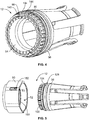
- Figures 3 is a perspective view of a portion of the backshell 12 showing the cavity insert 54 poised for loading into the cable follower 56.
- Figure 4 is a perspective view of a portion of the backshell 12 showing the cavity insert 54 loaded into the cable follower 56.
- the cable follower 56 includes key tabs 140 in the interior of the base ring 104.
- the key tabs 140 are configured to interface with the corresponding keying features 98 of the cavity insert 54.
- the keying feature 98 are slots or grooves formed in the cavity insert 54 that receive the key tabs 140 to align the cavity insert 54 with the cable follower 56.
- the cable follower 56 includes a follower shoulder 142 in the cavity of the base ring 104.
- the cavity insert 54 is received in the base ring 104 until a rim 144 at the front 90 of the cavity insert 54 engages and bottoms out against the follower shoulder 142.
- the follower shoulder 142 blocks rearward movement of the cavity insert 54 relative to the cable follower 56.
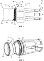
- Figure 5 is a perspective view of the backshell 12 showing the coupling nut 50 poised for coupling to the cable follower 56.
- the coupling nut 50 may be loaded over the front 100 of the cable follower 56.
- the coupling nut 50 includes a coupling nut shoulder 150 in the cavity 52.
- the coupling nut 50 may be loaded onto the front 100 of the cable follower 56 until the front 100 of the cable follower 56 bottoms out against the coupling nut shoulder 150.
- an opening 152 in the coupling nut 50 may be aligned with the retention groove 128 around the base ring 104.
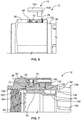
- Figure 6 is a partially assembled view of the backshell 12 showing the retention feature 76 poised for loading into the coupling nut 50.
- the retention feature 76 may be loaded into the pocket 78.
- the lug 130 may pass through the opening 152 into the retention groove 128 (shown in Figure 5 ) of the cable follower 56 to secure the coupling nut 50 to the cable follower 56.
- a plate 154 of the retention feature 76 engages the ratchet feature 66, such as the spring 70 of the ratchet feature 66, to hold the ratchet feature 66 in the coupling nut 50.
- Figure 7 is a cross-sectional view of a portion of the backshell 12 in an assembled state.
- Figure 7 illustrates the retention feature 76 coupled to the coupling nut 50.
- the lug 130 of the retention feature 76 is received in the retention groove 128.
- the pin 80 holds the retention feature 76 in the coupling nut 50.
- the retention feature 76 holds the ratchet feature 66 in the coupling nut 50.
- the plate 154 blocks the spring 70, which biases the ball bearing 68 into the ratchet slot 72 of the cable follower 56.
- the front 100 of the cable follower 56 is loaded against the coupling nut shoulder 150.
- the coupling nut 50 is freely rotatable relative to the cavity insert 54 and the cable follower 56.
- threads 156 of the coupling nut 50 at the front 60 may be threadably coupled to the second connector portion 14.
- the anti-rotation teeth 94 of the cavity insert 54 may engage the second connector portion 14 to stop or resist rotation of the cavity insert 54 and the cable follower 56 relative to the second connector portion 14.
- a space 158 is provided between the braid lip 96 and the interior of the base ring 104.
- the cable braid and/or the cable jacket of the cable 18 may be received in the space 158.
- a braid strap may be received in the space 158 to mechanically and electrically connect the cable braid to the braid lip 96 of the cavity insert 54.
- the spring fingers 106 extend rearward of the base ring 104. In an exemplary embodiment, the spring fingers 106 are tapered inward from the base ring 104.
- FIG 8 is a cross-sectional view of the backshell 12 in accordance with an exemplary embodiment.
- the retention feature 76 is illustrated as a captive ring 160 rather than the plug shown in Figure 7 .
- the captive ring 160 may extend at least partially circumferentially around the base ring 104 and may be captured in corresponding grooves 162, 164 in the base ring 104 and the coupling nut 50.
- Figure 9 is a cross-sectional view of the backshell 12 in accordance with an exemplary embodiment.
- the cable follower 56 has the spring fingers 106 extending at an angle, such as approximately a 45° angle.
- the cable channel axis 112 extends at an angle with respect to the cavity axis 82.
- the cable 18 may be loaded into the cable follower 56 through the rear of the base ring 104 and press downward into the spring fingers 106 through an opening in the top of the spring fingers 106.
- the spring fingers 106 are circumferentially disposed about a majority of the cable channel 110 to retain the cable 18 in the cable channel 110.
- the spring fingers 106 may be disposed at approximately 45°, 100°, 160°, 210°, 260° and 315° from vertical.
- the slightly larger gap (for example, end spring fingers disposed approximately 90° apart) between the top two spring fingers 106 provide a space to receive the cable 18 into the cable channel 110.
- the spring fingers 106 provide a generally uniform clamping force around the cable 18 to center the cable 18 in the cable channel 110.
- a band strap or zip tie may be used to wrap around the cable 18 and the spring fingers 106 to retain the cable 18 in the cable channel 110.
- Figure 10 is a partial-sectional view of the backshell 12 in accordance with an exemplary embodiment.
- the cable follower 56 has the spring fingers 106 extending at an angle, such as approximately a 90° angle.
- the cable channel axis 112 extends at an angle with respect to the cavity axis 82.
- the cable 18 may be loaded into the cable follower 56 through the rear of the base ring 104 and press downward into the spring fingers 106 through an opening along the rear of the spring fingers 106.
- the spring fingers 106 are circumferentially disposed about a majority of the cable channel 110 to retain the cable 18 in the cable channel 110.
- the spring fingers 106 provide a generally uniform clamping force around the cable 18 to center the cable 18 in the cable channel 110.
- a band strap or zip tie may be used to wrap around the cable 18 and the spring fingers 106 to retain the cable 18 in the cable channel 110.
Landscapes
- Details Of Connecting Devices For Male And Female Coupling (AREA)
Applications Claiming Priority (1)
| Application Number | Priority Date | Filing Date | Title |
|---|---|---|---|
| US15/240,064 US9960527B2 (en) | 2016-08-18 | 2016-08-18 | Electrical assembly having a backshell with a cable follower |
Publications (2)
| Publication Number | Publication Date |
|---|---|
| EP3285335A1 true EP3285335A1 (fr) | 2018-02-21 |
| EP3285335B1 EP3285335B1 (fr) | 2021-03-24 |
Family
ID=59592914
Family Applications (1)
| Application Number | Title | Priority Date | Filing Date |
|---|---|---|---|
| EP17185895.4A Active EP3285335B1 (fr) | 2016-08-18 | 2017-08-11 | Ensemble électrique comprenant une coque arrière comportant un suiveur de câble |
Country Status (2)
| Country | Link |
|---|---|
| US (1) | US9960527B2 (fr) |
| EP (1) | EP3285335B1 (fr) |
Families Citing this family (3)
| Publication number | Priority date | Publication date | Assignee | Title |
|---|---|---|---|---|
| JP6855280B2 (ja) * | 2017-02-28 | 2021-04-07 | 日本航空電子工業株式会社 | 保持部材 |
| KR102648083B1 (ko) * | 2018-09-10 | 2024-03-15 | 한국단자공업 주식회사 | 고전압 커넥터용 와이어 압착장치 |
| GB202011186D0 (en) * | 2020-07-20 | 2020-09-02 | Robinson Dominic James | Universal locking system for managing pre-wired data cable bundles |
Citations (9)
| Publication number | Priority date | Publication date | Assignee | Title |
|---|---|---|---|---|
| US3622942A (en) * | 1970-04-27 | 1971-11-23 | Thomas & Betts Corp | Strain relief |
| US3732526A (en) * | 1971-06-25 | 1973-05-08 | Bendix Corp | Electrical connector with improved cable support |
| US4808123A (en) * | 1987-02-04 | 1989-02-28 | Diverse Termination Products, Inc. | Self-locking strain-relief end bell for electrical connector assembly |
| WO1999040651A1 (fr) * | 1998-02-06 | 1999-08-12 | Palazzoli S.P.A. | Serre-cables pour prises et fiches electriques |
| US7635283B1 (en) * | 2008-11-24 | 2009-12-22 | Andrew Llc | Connector with retaining ring for coaxial cable and associated methods |
| US20090318033A1 (en) * | 2008-06-20 | 2009-12-24 | Tyco Electronics Corporation | Electrical connector with a compliant cable strain relief element |
| US20120100745A1 (en) * | 2010-10-25 | 2012-04-26 | Tyco Electronics Corporation | Rotationally configurable backshell for an electrical connector |
| US20140148044A1 (en) * | 2012-11-29 | 2014-05-29 | Anders Balcer | Hardline coaxial connector with a locking ferrule |
| US9197008B1 (en) * | 2014-08-26 | 2015-11-24 | Tyco Electronics Corporation | Electrical assembly having a threaded coupling nut and retaining ring |
Family Cites Families (12)
| Publication number | Priority date | Publication date | Assignee | Title |
|---|---|---|---|---|
| US2472986A (en) * | 1946-05-23 | 1949-06-14 | Jr Emil E Reder | Cord protector and strain reliever for use with electrical connectors |
| US5030135A (en) * | 1990-11-29 | 1991-07-09 | Compaq Computer Corporation | Cable strain relief device |
| US5933557A (en) * | 1996-11-19 | 1999-08-03 | Siecor Corporation | Multi-link boot assembly for cable connector |
| US6422884B1 (en) * | 2000-06-27 | 2002-07-23 | Sentinel Lighting Wiring Systems, Inc. | Pre-wired circuit component for flexible wiring system |
| US6419519B1 (en) * | 2000-08-01 | 2002-07-16 | Glenair Inc. | Strain relief for electrical connectors |
| US6478609B1 (en) * | 2000-10-02 | 2002-11-12 | Tyco Electronics Corporation | Strain relief assembly |
| US6846201B2 (en) * | 2002-12-20 | 2005-01-25 | The Boeing Company | Electrical cable clamping method and apparatus |
| US20140265308A1 (en) * | 2012-08-08 | 2014-09-18 | Power In Operation, LLC | Adjustable backshell for wiring harness |
| US9209571B2 (en) * | 2013-10-16 | 2015-12-08 | Tyco Electronics Corporation | Connector assembly having multiple shield current paths |
| US9627800B2 (en) * | 2015-06-10 | 2017-04-18 | Glenair, Inc. | Connector with spring-locked swing arms |
| US9413116B1 (en) * | 2015-08-03 | 2016-08-09 | Glenair, Inc. | Slotted, clamped termination ring for an electrical connector assembly |
| US20170085026A1 (en) * | 2015-09-21 | 2017-03-23 | Amphenol Corporation | High power electrical connector with strain relief |
-
2016
- 2016-08-18 US US15/240,064 patent/US9960527B2/en active Active
-
2017
- 2017-08-11 EP EP17185895.4A patent/EP3285335B1/fr active Active
Patent Citations (9)
| Publication number | Priority date | Publication date | Assignee | Title |
|---|---|---|---|---|
| US3622942A (en) * | 1970-04-27 | 1971-11-23 | Thomas & Betts Corp | Strain relief |
| US3732526A (en) * | 1971-06-25 | 1973-05-08 | Bendix Corp | Electrical connector with improved cable support |
| US4808123A (en) * | 1987-02-04 | 1989-02-28 | Diverse Termination Products, Inc. | Self-locking strain-relief end bell for electrical connector assembly |
| WO1999040651A1 (fr) * | 1998-02-06 | 1999-08-12 | Palazzoli S.P.A. | Serre-cables pour prises et fiches electriques |
| US20090318033A1 (en) * | 2008-06-20 | 2009-12-24 | Tyco Electronics Corporation | Electrical connector with a compliant cable strain relief element |
| US7635283B1 (en) * | 2008-11-24 | 2009-12-22 | Andrew Llc | Connector with retaining ring for coaxial cable and associated methods |
| US20120100745A1 (en) * | 2010-10-25 | 2012-04-26 | Tyco Electronics Corporation | Rotationally configurable backshell for an electrical connector |
| US20140148044A1 (en) * | 2012-11-29 | 2014-05-29 | Anders Balcer | Hardline coaxial connector with a locking ferrule |
| US9197008B1 (en) * | 2014-08-26 | 2015-11-24 | Tyco Electronics Corporation | Electrical assembly having a threaded coupling nut and retaining ring |
Also Published As
| Publication number | Publication date |
|---|---|
| US20180054022A1 (en) | 2018-02-22 |
| US9960527B2 (en) | 2018-05-01 |
| EP3285335B1 (fr) | 2021-03-24 |
Similar Documents
| Publication | Publication Date | Title |
|---|---|---|
| US10833432B2 (en) | Easily assembled coaxial cable and connector with rear body | |
| US9502824B2 (en) | Electrical connector | |
| EP2311152B1 (fr) | Ensemble connecteur électrique pourvu d'un connecteur électrique sollicité par ressort | |
| US9178290B2 (en) | Coaxial cable connector having a continuity element | |
| US7988476B2 (en) | Sealed plug assembly | |
| EP2551966B1 (fr) | Connecteur électrique avec un dispositif de serrage de câble | |
| EP2451020B1 (fr) | Module RF | |
| EP2362492B1 (fr) | Connecteur électrique | |
| US10581198B2 (en) | Connector | |
| EP3285335B1 (fr) | Ensemble électrique comprenant une coque arrière comportant un suiveur de câble | |
| CA2756189A1 (fr) | Ensemble connecteur rf | |
| JP5728549B2 (ja) | 電源ケーブルコネクタ | |
| JP6792354B2 (ja) | コネクタ | |
| EP3799215A1 (fr) | Connecteur de câble coaxial doté d'éléments de positionnement de tresse et port femelle de type f avec des caractéristiques encliquetables | |
| US20130267119A1 (en) | Electromagnetic interference shield for quick disconnect connector | |
| US4170393A (en) | Electrical connector with replaceable contacts | |
| EP3186856B1 (fr) | Ensemble électrique ayant un écrou d'accouplement fileté et bague de retenue | |
| US10601174B2 (en) | Electrical connector assembly with a locking device to stabilize the electrical connection | |
| US6194654B1 (en) | Shield connection system and connector using the same | |
| CN113437567A (zh) | 连接器及包括其的连接器组件 | |
| US20140045365A1 (en) | Adjustable backshell for wiring harness |
Legal Events
| Date | Code | Title | Description |
|---|---|---|---|
| PUAI | Public reference made under article 153(3) epc to a published international application that has entered the european phase |
Free format text: ORIGINAL CODE: 0009012 |
|
| STAA | Information on the status of an ep patent application or granted ep patent |
Free format text: STATUS: THE APPLICATION HAS BEEN PUBLISHED |
|
| AK | Designated contracting states |
Kind code of ref document: A1 Designated state(s): AL AT BE BG CH CY CZ DE DK EE ES FI FR GB GR HR HU IE IS IT LI LT LU LV MC MK MT NL NO PL PT RO RS SE SI SK SM TR |
|
| AX | Request for extension of the european patent |
Extension state: BA ME |
|
| STAA | Information on the status of an ep patent application or granted ep patent |
Free format text: STATUS: REQUEST FOR EXAMINATION WAS MADE |
|
| 17P | Request for examination filed |
Effective date: 20180821 |
|
| RBV | Designated contracting states (corrected) |
Designated state(s): AL AT BE BG CH CY CZ DE DK EE ES FI FR GB GR HR HU IE IS IT LI LT LU LV MC MK MT NL NO PL PT RO RS SE SI SK SM TR |
|
| STAA | Information on the status of an ep patent application or granted ep patent |
Free format text: STATUS: EXAMINATION IS IN PROGRESS |
|
| 17Q | First examination report despatched |
Effective date: 20200228 |
|
| GRAP | Despatch of communication of intention to grant a patent |
Free format text: ORIGINAL CODE: EPIDOSNIGR1 |
|
| STAA | Information on the status of an ep patent application or granted ep patent |
Free format text: STATUS: GRANT OF PATENT IS INTENDED |
|
| RIC1 | Information provided on ipc code assigned before grant |
Ipc: H01R 9/05 20060101ALI20201203BHEP Ipc: H01R 13/59 20060101ALN20201203BHEP Ipc: H01R 13/58 20060101AFI20201203BHEP |
|
| INTG | Intention to grant announced |
Effective date: 20201216 |
|
| GRAS | Grant fee paid |
Free format text: ORIGINAL CODE: EPIDOSNIGR3 |
|
| GRAA | (expected) grant |
Free format text: ORIGINAL CODE: 0009210 |
|
| STAA | Information on the status of an ep patent application or granted ep patent |
Free format text: STATUS: THE PATENT HAS BEEN GRANTED |
|
| AK | Designated contracting states |
Kind code of ref document: B1 Designated state(s): AL AT BE BG CH CY CZ DE DK EE ES FI FR GB GR HR HU IE IS IT LI LT LU LV MC MK MT NL NO PL PT RO RS SE SI SK SM TR |
|
| REG | Reference to a national code |
Ref country code: GB Ref legal event code: FG4D |
|
| REG | Reference to a national code |
Ref country code: CH Ref legal event code: EP |
|
| REG | Reference to a national code |
Ref country code: DE Ref legal event code: R096 Ref document number: 602017035102 Country of ref document: DE |
|
| REG | Reference to a national code |
Ref country code: IE Ref legal event code: FG4D |
|
| REG | Reference to a national code |
Ref country code: AT Ref legal event code: REF Ref document number: 1375453 Country of ref document: AT Kind code of ref document: T Effective date: 20210415 |
|
| REG | Reference to a national code |
Ref country code: LT Ref legal event code: MG9D |
|
| PG25 | Lapsed in a contracting state [announced via postgrant information from national office to epo] |
Ref country code: BG Free format text: LAPSE BECAUSE OF FAILURE TO SUBMIT A TRANSLATION OF THE DESCRIPTION OR TO PAY THE FEE WITHIN THE PRESCRIBED TIME-LIMIT Effective date: 20210624 Ref country code: NO Free format text: LAPSE BECAUSE OF FAILURE TO SUBMIT A TRANSLATION OF THE DESCRIPTION OR TO PAY THE FEE WITHIN THE PRESCRIBED TIME-LIMIT Effective date: 20210624 Ref country code: GR Free format text: LAPSE BECAUSE OF FAILURE TO SUBMIT A TRANSLATION OF THE DESCRIPTION OR TO PAY THE FEE WITHIN THE PRESCRIBED TIME-LIMIT Effective date: 20210625 Ref country code: HR Free format text: LAPSE BECAUSE OF FAILURE TO SUBMIT A TRANSLATION OF THE DESCRIPTION OR TO PAY THE FEE WITHIN THE PRESCRIBED TIME-LIMIT Effective date: 20210324 Ref country code: FI Free format text: LAPSE BECAUSE OF FAILURE TO SUBMIT A TRANSLATION OF THE DESCRIPTION OR TO PAY THE FEE WITHIN THE PRESCRIBED TIME-LIMIT Effective date: 20210324 |
|
| PG25 | Lapsed in a contracting state [announced via postgrant information from national office to epo] |
Ref country code: RS Free format text: LAPSE BECAUSE OF FAILURE TO SUBMIT A TRANSLATION OF THE DESCRIPTION OR TO PAY THE FEE WITHIN THE PRESCRIBED TIME-LIMIT Effective date: 20210324 Ref country code: LV Free format text: LAPSE BECAUSE OF FAILURE TO SUBMIT A TRANSLATION OF THE DESCRIPTION OR TO PAY THE FEE WITHIN THE PRESCRIBED TIME-LIMIT Effective date: 20210324 Ref country code: SE Free format text: LAPSE BECAUSE OF FAILURE TO SUBMIT A TRANSLATION OF THE DESCRIPTION OR TO PAY THE FEE WITHIN THE PRESCRIBED TIME-LIMIT Effective date: 20210324 |
|
| REG | Reference to a national code |
Ref country code: NL Ref legal event code: MP Effective date: 20210324 |
|
| REG | Reference to a national code |
Ref country code: AT Ref legal event code: MK05 Ref document number: 1375453 Country of ref document: AT Kind code of ref document: T Effective date: 20210324 |
|
| PG25 | Lapsed in a contracting state [announced via postgrant information from national office to epo] |
Ref country code: NL Free format text: LAPSE BECAUSE OF FAILURE TO SUBMIT A TRANSLATION OF THE DESCRIPTION OR TO PAY THE FEE WITHIN THE PRESCRIBED TIME-LIMIT Effective date: 20210324 |
|
| PG25 | Lapsed in a contracting state [announced via postgrant information from national office to epo] |
Ref country code: EE Free format text: LAPSE BECAUSE OF FAILURE TO SUBMIT A TRANSLATION OF THE DESCRIPTION OR TO PAY THE FEE WITHIN THE PRESCRIBED TIME-LIMIT Effective date: 20210324 Ref country code: CZ Free format text: LAPSE BECAUSE OF FAILURE TO SUBMIT A TRANSLATION OF THE DESCRIPTION OR TO PAY THE FEE WITHIN THE PRESCRIBED TIME-LIMIT Effective date: 20210324 Ref country code: LT Free format text: LAPSE BECAUSE OF FAILURE TO SUBMIT A TRANSLATION OF THE DESCRIPTION OR TO PAY THE FEE WITHIN THE PRESCRIBED TIME-LIMIT Effective date: 20210324 Ref country code: AT Free format text: LAPSE BECAUSE OF FAILURE TO SUBMIT A TRANSLATION OF THE DESCRIPTION OR TO PAY THE FEE WITHIN THE PRESCRIBED TIME-LIMIT Effective date: 20210324 Ref country code: SM Free format text: LAPSE BECAUSE OF FAILURE TO SUBMIT A TRANSLATION OF THE DESCRIPTION OR TO PAY THE FEE WITHIN THE PRESCRIBED TIME-LIMIT Effective date: 20210324 |
|
| PG25 | Lapsed in a contracting state [announced via postgrant information from national office to epo] |
Ref country code: IS Free format text: LAPSE BECAUSE OF FAILURE TO SUBMIT A TRANSLATION OF THE DESCRIPTION OR TO PAY THE FEE WITHIN THE PRESCRIBED TIME-LIMIT Effective date: 20210724 Ref country code: PL Free format text: LAPSE BECAUSE OF FAILURE TO SUBMIT A TRANSLATION OF THE DESCRIPTION OR TO PAY THE FEE WITHIN THE PRESCRIBED TIME-LIMIT Effective date: 20210324 Ref country code: PT Free format text: LAPSE BECAUSE OF FAILURE TO SUBMIT A TRANSLATION OF THE DESCRIPTION OR TO PAY THE FEE WITHIN THE PRESCRIBED TIME-LIMIT Effective date: 20210726 Ref country code: RO Free format text: LAPSE BECAUSE OF FAILURE TO SUBMIT A TRANSLATION OF THE DESCRIPTION OR TO PAY THE FEE WITHIN THE PRESCRIBED TIME-LIMIT Effective date: 20210324 Ref country code: SK Free format text: LAPSE BECAUSE OF FAILURE TO SUBMIT A TRANSLATION OF THE DESCRIPTION OR TO PAY THE FEE WITHIN THE PRESCRIBED TIME-LIMIT Effective date: 20210324 |
|
| REG | Reference to a national code |
Ref country code: DE Ref legal event code: R097 Ref document number: 602017035102 Country of ref document: DE |
|
| PG25 | Lapsed in a contracting state [announced via postgrant information from national office to epo] |
Ref country code: AL Free format text: LAPSE BECAUSE OF FAILURE TO SUBMIT A TRANSLATION OF THE DESCRIPTION OR TO PAY THE FEE WITHIN THE PRESCRIBED TIME-LIMIT Effective date: 20210324 Ref country code: DK Free format text: LAPSE BECAUSE OF FAILURE TO SUBMIT A TRANSLATION OF THE DESCRIPTION OR TO PAY THE FEE WITHIN THE PRESCRIBED TIME-LIMIT Effective date: 20210324 Ref country code: ES Free format text: LAPSE BECAUSE OF FAILURE TO SUBMIT A TRANSLATION OF THE DESCRIPTION OR TO PAY THE FEE WITHIN THE PRESCRIBED TIME-LIMIT Effective date: 20210324 |
|
| PLBE | No opposition filed within time limit |
Free format text: ORIGINAL CODE: 0009261 |
|
| STAA | Information on the status of an ep patent application or granted ep patent |
Free format text: STATUS: NO OPPOSITION FILED WITHIN TIME LIMIT |
|
| PG25 | Lapsed in a contracting state [announced via postgrant information from national office to epo] |
Ref country code: SI Free format text: LAPSE BECAUSE OF FAILURE TO SUBMIT A TRANSLATION OF THE DESCRIPTION OR TO PAY THE FEE WITHIN THE PRESCRIBED TIME-LIMIT Effective date: 20210324 |
|
| 26N | No opposition filed |
Effective date: 20220104 |
|
| REG | Reference to a national code |
Ref country code: CH Ref legal event code: PL |
|
| PG25 | Lapsed in a contracting state [announced via postgrant information from national office to epo] |
Ref country code: MC Free format text: LAPSE BECAUSE OF FAILURE TO SUBMIT A TRANSLATION OF THE DESCRIPTION OR TO PAY THE FEE WITHIN THE PRESCRIBED TIME-LIMIT Effective date: 20210324 |
|
| REG | Reference to a national code |
Ref country code: BE Ref legal event code: MM Effective date: 20210831 |
|
| PG25 | Lapsed in a contracting state [announced via postgrant information from national office to epo] |
Ref country code: LI Free format text: LAPSE BECAUSE OF NON-PAYMENT OF DUE FEES Effective date: 20210831 Ref country code: CH Free format text: LAPSE BECAUSE OF NON-PAYMENT OF DUE FEES Effective date: 20210831 |
|
| PG25 | Lapsed in a contracting state [announced via postgrant information from national office to epo] |
Ref country code: IS Free format text: LAPSE BECAUSE OF FAILURE TO SUBMIT A TRANSLATION OF THE DESCRIPTION OR TO PAY THE FEE WITHIN THE PRESCRIBED TIME-LIMIT Effective date: 20210724 Ref country code: LU Free format text: LAPSE BECAUSE OF NON-PAYMENT OF DUE FEES Effective date: 20210811 |
|
| PG25 | Lapsed in a contracting state [announced via postgrant information from national office to epo] |
Ref country code: IE Free format text: LAPSE BECAUSE OF NON-PAYMENT OF DUE FEES Effective date: 20210811 Ref country code: BE Free format text: LAPSE BECAUSE OF NON-PAYMENT OF DUE FEES Effective date: 20210831 |
|
| PG25 | Lapsed in a contracting state [announced via postgrant information from national office to epo] |
Ref country code: IT Free format text: LAPSE BECAUSE OF FAILURE TO SUBMIT A TRANSLATION OF THE DESCRIPTION OR TO PAY THE FEE WITHIN THE PRESCRIBED TIME-LIMIT Effective date: 20210324 |
|
| PG25 | Lapsed in a contracting state [announced via postgrant information from national office to epo] |
Ref country code: HU Free format text: LAPSE BECAUSE OF FAILURE TO SUBMIT A TRANSLATION OF THE DESCRIPTION OR TO PAY THE FEE WITHIN THE PRESCRIBED TIME-LIMIT; INVALID AB INITIO Effective date: 20170811 |
|
| PG25 | Lapsed in a contracting state [announced via postgrant information from national office to epo] |
Ref country code: CY Free format text: LAPSE BECAUSE OF FAILURE TO SUBMIT A TRANSLATION OF THE DESCRIPTION OR TO PAY THE FEE WITHIN THE PRESCRIBED TIME-LIMIT Effective date: 20210324 |
|
| PGFP | Annual fee paid to national office [announced via postgrant information from national office to epo] |
Ref country code: FR Payment date: 20230608 Year of fee payment: 7 |
|
| PGFP | Annual fee paid to national office [announced via postgrant information from national office to epo] |
Ref country code: GB Payment date: 20230622 Year of fee payment: 7 |
|
| PGFP | Annual fee paid to national office [announced via postgrant information from national office to epo] |
Ref country code: DE Payment date: 20230613 Year of fee payment: 7 |
|
| PG25 | Lapsed in a contracting state [announced via postgrant information from national office to epo] |
Ref country code: MK Free format text: LAPSE BECAUSE OF FAILURE TO SUBMIT A TRANSLATION OF THE DESCRIPTION OR TO PAY THE FEE WITHIN THE PRESCRIBED TIME-LIMIT Effective date: 20210324 |