EP3285039A1 - Heat exchangers with multiple flow channels - Google Patents
Heat exchangers with multiple flow channels Download PDFInfo
- Publication number
- EP3285039A1 EP3285039A1 EP17186478.8A EP17186478A EP3285039A1 EP 3285039 A1 EP3285039 A1 EP 3285039A1 EP 17186478 A EP17186478 A EP 17186478A EP 3285039 A1 EP3285039 A1 EP 3285039A1
- Authority
- EP
- European Patent Office
- Prior art keywords
- channel
- forming
- channels
- heat exchanger
- wound around
- Prior art date
- Legal status (The legal status is an assumption and is not a legal conclusion. Google has not performed a legal analysis and makes no representation as to the accuracy of the status listed.)
- Granted
Links
Images

Classifications
-
- F—MECHANICAL ENGINEERING; LIGHTING; HEATING; WEAPONS; BLASTING
- F28—HEAT EXCHANGE IN GENERAL
- F28D—HEAT-EXCHANGE APPARATUS, NOT PROVIDED FOR IN ANOTHER SUBCLASS, IN WHICH THE HEAT-EXCHANGE MEDIA DO NOT COME INTO DIRECT CONTACT
- F28D7/00—Heat-exchange apparatus having stationary tubular conduit assemblies for both heat-exchange media, the media being in contact with different sides of a conduit wall
- F28D7/0008—Heat-exchange apparatus having stationary tubular conduit assemblies for both heat-exchange media, the media being in contact with different sides of a conduit wall the conduits for one medium being in heat conductive contact with the conduits for the other medium
- F28D7/0016—Heat-exchange apparatus having stationary tubular conduit assemblies for both heat-exchange media, the media being in contact with different sides of a conduit wall the conduits for one medium being in heat conductive contact with the conduits for the other medium the conduits for one medium or the conduits for both media being bent
-
- F—MECHANICAL ENGINEERING; LIGHTING; HEATING; WEAPONS; BLASTING
- F28—HEAT EXCHANGE IN GENERAL
- F28D—HEAT-EXCHANGE APPARATUS, NOT PROVIDED FOR IN ANOTHER SUBCLASS, IN WHICH THE HEAT-EXCHANGE MEDIA DO NOT COME INTO DIRECT CONTACT
- F28D7/00—Heat-exchange apparatus having stationary tubular conduit assemblies for both heat-exchange media, the media being in contact with different sides of a conduit wall
- F28D7/02—Heat-exchange apparatus having stationary tubular conduit assemblies for both heat-exchange media, the media being in contact with different sides of a conduit wall the conduits being helically coiled
- F28D7/024—Heat-exchange apparatus having stationary tubular conduit assemblies for both heat-exchange media, the media being in contact with different sides of a conduit wall the conduits being helically coiled the conduits of only one medium being helically coiled tubes, the coils having a cylindrical configuration
-
- F—MECHANICAL ENGINEERING; LIGHTING; HEATING; WEAPONS; BLASTING
- F28—HEAT EXCHANGE IN GENERAL
- F28F—DETAILS OF HEAT-EXCHANGE AND HEAT-TRANSFER APPARATUS, OF GENERAL APPLICATION
- F28F21/00—Constructions of heat-exchange apparatus characterised by the selection of particular materials
- F28F21/08—Constructions of heat-exchange apparatus characterised by the selection of particular materials of metal
- F28F21/081—Heat exchange elements made from metals or metal alloys
-
- F—MECHANICAL ENGINEERING; LIGHTING; HEATING; WEAPONS; BLASTING
- F28—HEAT EXCHANGE IN GENERAL
- F28F—DETAILS OF HEAT-EXCHANGE AND HEAT-TRANSFER APPARATUS, OF GENERAL APPLICATION
- F28F7/00—Elements not covered by group F28F1/00, F28F3/00 or F28F5/00
- F28F7/02—Blocks traversed by passages for heat-exchange media
-
- F—MECHANICAL ENGINEERING; LIGHTING; HEATING; WEAPONS; BLASTING
- F28—HEAT EXCHANGE IN GENERAL
- F28F—DETAILS OF HEAT-EXCHANGE AND HEAT-TRANSFER APPARATUS, OF GENERAL APPLICATION
- F28F2255/00—Heat exchanger elements made of materials having special features or resulting from particular manufacturing processes
- F28F2255/18—Heat exchanger elements made of materials having special features or resulting from particular manufacturing processes sintered
-
- F—MECHANICAL ENGINEERING; LIGHTING; HEATING; WEAPONS; BLASTING
- F28—HEAT EXCHANGE IN GENERAL
- F28F—DETAILS OF HEAT-EXCHANGE AND HEAT-TRANSFER APPARATUS, OF GENERAL APPLICATION
- F28F2275/00—Fastening; Joining
- F28F2275/06—Fastening; Joining by welding
-
- Y—GENERAL TAGGING OF NEW TECHNOLOGICAL DEVELOPMENTS; GENERAL TAGGING OF CROSS-SECTIONAL TECHNOLOGIES SPANNING OVER SEVERAL SECTIONS OF THE IPC; TECHNICAL SUBJECTS COVERED BY FORMER USPC CROSS-REFERENCE ART COLLECTIONS [XRACs] AND DIGESTS
- Y02—TECHNOLOGIES OR APPLICATIONS FOR MITIGATION OR ADAPTATION AGAINST CLIMATE CHANGE
- Y02P—CLIMATE CHANGE MITIGATION TECHNOLOGIES IN THE PRODUCTION OR PROCESSING OF GOODS
- Y02P10/00—Technologies related to metal processing
- Y02P10/25—Process efficiency
Definitions
- the present disclosure relates to heat exchangers, more specifically to heat exchangers having multiple channels.
- two different fluids can be used.
- One fluid can cool and/or heat the other fluid.
- Existing structures have traditionally had limited complexity in their design, and thus have not fully maximized thermal efficiency.
- a heat exchanger can include a monolithically formed body defining at least two channels configured to allow fluid to flow therethrough, at least one of the at least two channels at least partially wrapping around or within at least one other of the at least two channels.
- the at least two channels can include a first channel and a second channel, wherein the first channel is at least partially wound around or within the second channel.
- the first channel can be helically wound around the second channel, for example.
- the first channel can be non-helically wound also or in any other suitable manner.
- the first channel can be wound around the second channel outside of the second channel. In certain embodiments, the first channel can be wound around the second channel inside the second channel such that fluid within the second channel contacts an outer wall of the first channel.
- the second channel can be straight.
- the second channel can be cylindrical in shape (e.g., having a circular cross-section). Any other suitable shape is contemplated herein.
- the body can be formed of metal or any other suitable material.
- the body can be laser sintered, for example. Any other suitable method can be used to form the body (e.g., electron-beam welding)
- a method of forming a heat exchanger includes monolithically forming a body to define at least two channels configured to allow fluid to flow therethrough, at least one of the at least two channels at least partially wrapping around or within at least one other of the at least two channels.
- forming the body to define at least two channels includes defining a first channel and a second channel such that the first channel is wound around or within the second channel.
- Forming the body can include forming the first channel such that the first channel is helically or non-helically wound around the second channel.
- Forming the body can include forming the first channel such that the first channel is wound around the second channel outside of the second channel. Forming the body can include forming the first channel such that the first channel is wound around the second channel inside the second channel such that fluid within the second channel contacts an outer wall of the first channel.
- Forming the body can include forming the second channel such that the second channel is straight. In certain embodiments, forming the body can include forming the second channel such that the second channel is cylindrical in shape.
- forming the body can include forming the body from metal powder. Forming the body includes laser sintering metal powder.
- FIG. 1 an illustrative view of an embodiment of a heat exchanger in accordance with the disclosure is shown in Fig. 1 and is designated generally by reference character 100.
- FIGs. 2A-4 Other embodiments and/or aspects of this disclosure are shown in Figs. 2A-4 .
- the systems and methods described herein can be used to enhance thermal efficiency of heat exchangers.
- a heat exchanger 100 can include a monolithically formed body 102 defining at least two channels configured to allow fluid to flow therethrough. At least one of the at least two channels at least partially wraps around or within at least one other of the at least two channels.
- the at least two channels can include at least a first channel 101 and a second channel 103. Any other suitable number of channels (e.g., third, further, fifth, etc.) is contemplated herein.
- the body 102 is not shown in Figs. 1 and 2A because the first and second channels 101, 103 are shown in inverse for clarity.
- the body 102a can be any suitable shape or size, and made for any suitable application.
- At least the first channel 101 can be at least partially wound around or within the second channel 103, or at least the second channel 103 can be at least partially wound around or within the first channel 101, or at least the first channel 101 and the second channel 013 can be at least partially wound around each other.
- the first channel 101 can be helically or non-helically wound around the second channel 103, as shown, or vice versa. Any other type of winding is contemplated herein, and the first channel 101 need not be smooth.
- the first channel 101 and the second channel 103 are fluidly isolated from each other and/or can have any suitable shape (e.g., helical, non-helical, straight, etc.).
- a heat exchanger 300 can include a body 302 that defines a first channel 301 that is wound within body 302 to form a second channel 303 such that fluid within the second channel 303 contacts an outer wall of the first channel 301.
- the first channel 301 and the second channel 303 are fluidly isolated from each other.
- the first channel 301 can terminate into the body 302 as shown in Fig. 3 to create outlets 304, for example.
- the second channel 103, 303 can be straight or any other suitable shape (e.g., curved). In certain embodiments, the second channel 103, 303 can be cylindrical in shape (e.g., have a circular cross-section). Any other suitable shape is contemplated herein.
- the body 102, 302 can be formed of metal (e.g., Cu, Ni alloy, Al, Ti alloy) or any other suitable material. In certain embodiments, the body 102, 302 can be laser sintered.
- a method of forming a heat exchanger includes monolithically forming a body 102, 302 to define at least two channels configured to allow fluid to flow therethrough, at least one of the at least two channels at least partially wrapping around or within at least one other of the at least two channels.
- forming the body to define at least two channels can include defining a first channel 101, 301 and a second channel 103, 303 such that the first channel 101, 301 is at least partially wound around or within the second channel 103, 303.
- Forming the body 102, 302 can include forming the first channel 101, 301 such that the first channel 101, 301 is helically wound around the second channel 103, 303.
- Forming the body 102 can include forming the first channel 101 such that the first channel 101 is wound around the second channel 103 outside of the second channel 103.
- Forming the body 302 can include forming the first channel 301 such that the first channel 301 is wound around the second channel 303 inside the second channel 303 such that fluid within the second channel 303 contacts an outer wall of the first channel 301.
- Forming the body 102, 302 can include forming the second channel 103, 303 such that the second channel 103, 303 is straight. In certain embodiments, forming the body 102, 302 can include forming the second channel 103, 303 such that the second channel 103, 303 is cylindrical in shape.
- forming the body 102, 302 can include forming the body 102, 302 from metal powder. Forming the body 102, 302 can include laser sintering metal powder.
- Embodiments as described above can be used for cooling and/or heating applications. While embodiments are shown having two channels, any suitable number of fluidly isolated channels is contemplated herein (e.g., two helical first channels around a second channel to form a double helix). Flow can be passed through the first and second channels in a concurrent direction or a different direction. The first channel can be wrapped around the second channel as tightly (amount of winds per unit length of the second channel) as is suitable.
- Additive manufacturing allows unique configurations that cannot be produced in current machining practices.
- Embodiments as described herein include internal passages that allow flow of two different fluids around each other.
Landscapes
- Engineering & Computer Science (AREA)
- Physics & Mathematics (AREA)
- Thermal Sciences (AREA)
- Mechanical Engineering (AREA)
- General Engineering & Computer Science (AREA)
- Heat-Exchange Devices With Radiators And Conduit Assemblies (AREA)
- Powder Metallurgy (AREA)
Abstract
Description
- The present disclosure relates to heat exchangers, more specifically to heat exchangers having multiple channels.
- In certain heat exchanger systems, two different fluids can be used. One fluid can cool and/or heat the other fluid. Existing structures have traditionally had limited complexity in their design, and thus have not fully maximized thermal efficiency.
- Such conventional methods and systems have generally been considered satisfactory for their intended purpose. However, there is still a need in the art for improved heat exchangers. The present disclosure provides a solution for this need.
- A heat exchanger can include a monolithically formed body defining at least two channels configured to allow fluid to flow therethrough, at least one of the at least two channels at least partially wrapping around or within at least one other of the at least two channels. In certain embodiments, the at least two channels can include a first channel and a second channel, wherein the first channel is at least partially wound around or within the second channel.
- The first channel can be helically wound around the second channel, for example. The first channel can be non-helically wound also or in any other suitable manner.
- In certain embodiments, the first channel can be wound around the second channel outside of the second channel. In certain embodiments, the first channel can be wound around the second channel inside the second channel such that fluid within the second channel contacts an outer wall of the first channel.
- The second channel can be straight. In certain embodiments, the second channel can be cylindrical in shape (e.g., having a circular cross-section). Any other suitable shape is contemplated herein.
- The body can be formed of metal or any other suitable material. In certain embodiments, the body can be laser sintered, for example. Any other suitable method can be used to form the body (e.g., electron-beam welding)
- A method of forming a heat exchanger includes monolithically forming a body to define at least two channels configured to allow fluid to flow therethrough, at least one of the at least two channels at least partially wrapping around or within at least one other of the at least two channels. In certain embodiments, forming the body to define at least two channels includes defining a first channel and a second channel such that the first channel is wound around or within the second channel. Forming the body can include forming the first channel such that the first channel is helically or non-helically wound around the second channel.
- Forming the body can include forming the first channel such that the first channel is wound around the second channel outside of the second channel. Forming the body can include forming the first channel such that the first channel is wound around the second channel inside the second channel such that fluid within the second channel contacts an outer wall of the first channel.
- Forming the body can include forming the second channel such that the second channel is straight. In certain embodiments, forming the body can include forming the second channel such that the second channel is cylindrical in shape.
- In certain embodiments, forming the body can include forming the body from metal powder. Forming the body includes laser sintering metal powder.
- These and other features of the systems and methods of the subject disclosure will become more readily apparent to those skilled in the art from the following detailed description taken in conjunction with the drawings.
- So that those skilled in the art to which the subject disclosure appertains will readily understand how to make and use the devices and methods of the subject disclosure without undue experimentation, embodiments thereof will be described in detail herein below with reference to certain figures, wherein:
-
Fig. 1 is a perspective view of a flow volume (inverse of structure) of an embodiment of a heat exchanger in accordance with this disclosure, showing a first channel wrapped around a second channel; -
Fig. 2A is a side view of the embodiment ofFig. 1 ; -
Fig. 2B is a sectional view of the embodiment ofFig. 1 ; -
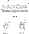
Fig. 3 is a side, partially cross-sectional view of an embodiment of a heat exchanger in accordance with this disclosure, showing a first flow channel wrapped inside a second flow channel, the second flow channel shown in cross-section; -
Fig. 4A is a plan view of the embodiment ofFig. 3 ; and -
Fig. 4B is a sectional view of the embodiment ofFig. 3 . - Reference will now be made to the drawings wherein like reference numerals identify similar structural features or aspects of the subject disclosure. For purposes of explanation and illustration, and not limitation, an illustrative view of an embodiment of a heat exchanger in accordance with the disclosure is shown in
Fig. 1 and is designated generally byreference character 100. Other embodiments and/or aspects of this disclosure are shown inFigs. 2A-4 . The systems and methods described herein can be used to enhance thermal efficiency of heat exchangers. - Referring to
Figs. 1, 2A, and 2B , aheat exchanger 100 can include a monolithically formedbody 102 defining at least two channels configured to allow fluid to flow therethrough. At least one of the at least two channels at least partially wraps around or within at least one other of the at least two channels. In certain embodiments, the at least two channels can include at least afirst channel 101 and asecond channel 103. Any other suitable number of channels (e.g., third, further, fifth, etc.) is contemplated herein. Thebody 102 is not shown inFigs. 1 and 2A because the first andsecond channels - At least the
first channel 101 can be at least partially wound around or within thesecond channel 103, or at least thesecond channel 103 can be at least partially wound around or within thefirst channel 101, or at least thefirst channel 101 and the second channel 013 can be at least partially wound around each other. For example, thefirst channel 101 can be helically or non-helically wound around thesecond channel 103, as shown, or vice versa. Any other type of winding is contemplated herein, and thefirst channel 101 need not be smooth. Thefirst channel 101 and thesecond channel 103 are fluidly isolated from each other and/or can have any suitable shape (e.g., helical, non-helical, straight, etc.). - In certain embodiments, the
first channel 101 can be wound around thesecond channel 103 outside of thesecond channel 103 as shown inFigs. 1-2B . Referring toFig. 3 and 4 , in certain embodiments, aheat exchanger 300 can include abody 302 that defines afirst channel 301 that is wound withinbody 302 to form asecond channel 303 such that fluid within thesecond channel 303 contacts an outer wall of thefirst channel 301. - The
first channel 301 and thesecond channel 303 are fluidly isolated from each other. Thefirst channel 301 can terminate into thebody 302 as shown inFig. 3 to createoutlets 304, for example. - The
second channel second channel - The
body body - A method of forming a heat exchanger includes monolithically forming a
body first channel second channel first channel second channel body first channel first channel second channel - Forming the
body 102 can include forming thefirst channel 101 such that thefirst channel 101 is wound around thesecond channel 103 outside of thesecond channel 103. Forming thebody 302 can include forming thefirst channel 301 such that thefirst channel 301 is wound around thesecond channel 303 inside thesecond channel 303 such that fluid within thesecond channel 303 contacts an outer wall of thefirst channel 301. - Forming the
body second channel second channel body second channel second channel - In certain embodiments, forming the
body body body - Embodiments as described above can be used for cooling and/or heating applications. While embodiments are shown having two channels, any suitable number of fluidly isolated channels is contemplated herein (e.g., two helical first channels around a second channel to form a double helix). Flow can be passed through the first and second channels in a concurrent direction or a different direction. The first channel can be wrapped around the second channel as tightly (amount of winds per unit length of the second channel) as is suitable.
- Additive manufacturing allows unique configurations that cannot be produced in current machining practices. Embodiments as described herein include internal passages that allow flow of two different fluids around each other.
- The methods and systems of the present disclosure, as described above and shown in the drawings, provide for heat exchangers with superior properties. While the apparatus and methods of the subject disclosure have been shown and described with reference to embodiments, those skilled in the art will readily appreciate that changes and/or modifications may be made thereto without departing from the spirit of the invention as defined by the claims.
Claims (15)
- A heat exchanger (100), comprising:a monolithically formed body (102) defining at least two channels (101, 103) configured to allow fluid to flow therethrough, at least one (101) of the at least two channels at least partially wrapping around or within at least one other of the at least two channels (103).
- The heat exchanger of claim 1, wherein the at least two channels (101, 103) include a first channel (101) and a second channel (103), wherein the first channel (101) is wound around or within the second channel (103).
- The heat exchanger of claim 2, wherein the first channel (101) is helically or non-helically wound around the second channel (103).
- The heat exchanger of claim 2, wherein the first channel (101) is wound around the second channel outside of the second channel (103).
- The heat exchanger of claim 2, wherein the first channel (101) is wound within the second channel (103) inside the second channel (103) such that fluid within the second channel (103) contacts an outer wall of the first channel (101).
- The heat exchanger of claim 2, wherein the second channel (103) is straight, or wherein the second channel (103) is cylindrical in shape.
- The heat exchanger of claim 1 or 2, wherein the body (102) is formed of metal.
- The heat exchanger of claim 1 or 2, wherein the body (102) is laser sintered or electron-beam welded.
- A method of forming a heat exchanger, comprising monolithically forming a body (102) to define at least two channels (101, 103)configured to allow fluid to flow therethrough, at least one (101) of the at least two channels (101, 103) at least partially wrapping around or within at least one other of the at least two channels (103).
- The method of claim 9, wherein forming the body (102) to define at least two channels includes defining a first channel (101) and a second channel (103) such that the first channel (101) is wound around or within the second channel (103).
- The method of claim 10, wherein forming the body (102) includes forming the first channel (101) such that the first channel (141) is helically or non-helically wound around the second channel (103).
- The method of claim 10, wherein forming the body (102) includes forming the first channel (101) such that the first channel (101) is wound around the second channel (103) outside of the second channel (103).
- The method of claim 10, wherein forming the body (102) includes forming the first channel (101) such that the first channel (101) is wound around the second channel (103) inside the second channel (103) such that fluid within the second channel (103) contacts an outer wall of the first channel (101).
- The method of claim 10, wherein forming the body includes forming the second channel such that the second channel is straight, or wherein forming the body (102) includes forming the second channel (102) such that the second channel (102) is cylindrical in shape.
- The method of claim 10, wherein forming the body(102) includes forming the body (102) from metal powder, or wherein forming the body (102) includes laser sintering metal powder.
Priority Applications (1)
| Application Number | Priority Date | Filing Date | Title |
|---|---|---|---|
| EP23168084.4A EP4220063B1 (en) | 2016-08-16 | 2017-08-16 | A method of forming a heat exchanger |
Applications Claiming Priority (1)
| Application Number | Priority Date | Filing Date | Title |
|---|---|---|---|
| US15/238,513 US11346611B2 (en) | 2016-08-16 | 2016-08-16 | Heat exchangers with multiple flow channels |
Related Child Applications (1)
| Application Number | Title | Priority Date | Filing Date |
|---|---|---|---|
| EP23168084.4A Division EP4220063B1 (en) | 2016-08-16 | 2017-08-16 | A method of forming a heat exchanger |
Publications (2)
| Publication Number | Publication Date |
|---|---|
| EP3285039A1 true EP3285039A1 (en) | 2018-02-21 |
| EP3285039B1 EP3285039B1 (en) | 2023-04-19 |
Family
ID=59738138
Family Applications (2)
| Application Number | Title | Priority Date | Filing Date |
|---|---|---|---|
| EP17186478.8A Active EP3285039B1 (en) | 2016-08-16 | 2017-08-16 | Heat exchangers with multiple flow channels |
| EP23168084.4A Active EP4220063B1 (en) | 2016-08-16 | 2017-08-16 | A method of forming a heat exchanger |
Family Applications After (1)
| Application Number | Title | Priority Date | Filing Date |
|---|---|---|---|
| EP23168084.4A Active EP4220063B1 (en) | 2016-08-16 | 2017-08-16 | A method of forming a heat exchanger |
Country Status (2)
| Country | Link |
|---|---|
| US (1) | US11346611B2 (en) |
| EP (2) | EP3285039B1 (en) |
Families Citing this family (10)
| Publication number | Priority date | Publication date | Assignee | Title |
|---|---|---|---|---|
| US11118838B2 (en) | 2019-02-20 | 2021-09-14 | Hamilton Sundstrand Corporation | Leaf-shaped geometry for heat exchanger core |
| US11359864B2 (en) | 2019-03-08 | 2022-06-14 | Hamilton Sundstrand Corporation | Rectangular helical core geometry for heat exchanger |
| US11274886B2 (en) | 2019-03-08 | 2022-03-15 | Hamilton Sundstrand Corporation | Heat exchanger header with fractal geometry |
| US11280550B2 (en) | 2019-03-08 | 2022-03-22 | Hamilton Sundstrand Corporation | Radially layered helical core geometry for heat exchanger |
| US11168942B2 (en) | 2019-03-08 | 2021-11-09 | Hamilton Sundstrand Corporation | Circular core for heat exchangers |
| US11754349B2 (en) | 2019-03-08 | 2023-09-12 | Hamilton Sundstrand Corporation | Heat exchanger |
| EP3760958B1 (en) | 2019-07-02 | 2023-10-18 | Hamilton Sundstrand Corporation | Heat exchanger |
| US11268770B2 (en) | 2019-09-06 | 2022-03-08 | Hamilton Sunstrand Corporation | Heat exchanger with radially converging manifold |
| US11209222B1 (en) | 2020-08-20 | 2021-12-28 | Hamilton Sundstrand Corporation | Spiral heat exchanger header |
| US11982499B2 (en) * | 2022-08-05 | 2024-05-14 | Hamilton Sundstrand Corporation | Heat exchanger with heat transfer augmentation features |
Citations (4)
| Publication number | Priority date | Publication date | Assignee | Title |
|---|---|---|---|---|
| US2611585A (en) * | 1948-03-30 | 1952-09-23 | Heat X Changer Co Inc | Heat exchanger |
| FR2592686A1 (en) * | 1986-01-08 | 1987-07-10 | Benarrouch Jacques | Device for heating diesel fuel in a diesel engine or the like |
| JP2003021476A (en) * | 2001-07-09 | 2003-01-24 | Daikin Ind Ltd | Heat exchanger manufacturing method |
| US20160116218A1 (en) * | 2014-10-27 | 2016-04-28 | Ebullient, Llc | Heat exchanger with helical passageways |
Family Cites Families (22)
| Publication number | Priority date | Publication date | Assignee | Title |
|---|---|---|---|---|
| US2260904A (en) * | 1938-07-30 | 1941-10-28 | Trico Products Corp | Windshield clearing system |
| US2409304A (en) * | 1943-04-01 | 1946-10-15 | Joseph I Morrison | Compressible core for cooling pipes |
| GB868388A (en) * | 1957-06-11 | 1961-05-17 | Du Pont | Process for stretching thermoplastic tubing |
| US3359753A (en) * | 1966-02-16 | 1967-12-26 | Arrow Tools Inc | Air dryer |
| US3513908A (en) * | 1967-08-18 | 1970-05-26 | Guru B Singh | Embedded tube heat exchanger |
| US3563212A (en) * | 1969-08-27 | 1971-02-16 | Steam Engines Systems Corp | Vapor generator |
| US3704748A (en) * | 1970-02-11 | 1972-12-05 | Ratheon Co | Heat transfer structure |
| US3899031A (en) * | 1974-06-17 | 1975-08-12 | Gen Electric | Vapor generator |
| US4277322A (en) * | 1980-02-04 | 1981-07-07 | Corning Glass Works | Oxygen sensor |
| EP0538244B1 (en) * | 1986-10-17 | 1996-05-22 | Board Of Regents, The University Of Texas System | Method and apparatus for producing parts by selective sintering |
| US5020319A (en) * | 1987-06-09 | 1991-06-04 | Ngk Spark Plug Co., Ltd. | Hollow heat-resisting body assembly for internal combustion engine |
| DE10234043A1 (en) * | 2002-07-26 | 2004-02-05 | Forschungszentrum Karlsruhe Gmbh | Microstructure apparatus for heating a fluid |
| JP2005076915A (en) | 2003-08-28 | 2005-03-24 | Kobe Steel Ltd | Composite heat exchanger tube |
| JP2008121908A (en) | 2006-11-08 | 2008-05-29 | Sumitomo Light Metal Ind Ltd | Heat exchanger |
| ATE544546T1 (en) | 2006-12-14 | 2012-02-15 | Cta Technology Proprietary Ltd | METHOD FOR PRODUCING A MULTI-CHANNEL COPPER TUBE AND DEVICE FOR PRODUCING THE TUBE |
| JP2009281711A (en) | 2008-05-26 | 2009-12-03 | Usui Kokusai Sangyo Kaisha Ltd | Double tube bending method, double tube bent by the method, and double tube type heat exchanger using the double tube |
| JP4636204B2 (en) * | 2008-12-19 | 2011-02-23 | ダイキン工業株式会社 | Geothermal heat exchanger and air conditioning system including the same |
| US9134072B2 (en) | 2010-03-15 | 2015-09-15 | The Trustees Of Dartmouth College | Geometry of heat exchanger with high efficiency |
| CN103292620B (en) | 2013-05-30 | 2015-10-21 | 西安交通大学 | A kind of Novel telescopic heat exchange tube |
| JP6043704B2 (en) | 2013-09-19 | 2016-12-14 | 東京瓦斯株式会社 | Motor cooler and method for manufacturing motor cooler |
| US20160025422A1 (en) | 2014-07-22 | 2016-01-28 | Hamilton Sundstrand Space Systems International, Inc. | Heat transfer plate |
| US10995996B2 (en) | 2014-10-07 | 2021-05-04 | Unison Industries, Llc | Multi-branch furcating flow heat exchanger |
-
2016
- 2016-08-16 US US15/238,513 patent/US11346611B2/en active Active
-
2017
- 2017-08-16 EP EP17186478.8A patent/EP3285039B1/en active Active
- 2017-08-16 EP EP23168084.4A patent/EP4220063B1/en active Active
Patent Citations (4)
| Publication number | Priority date | Publication date | Assignee | Title |
|---|---|---|---|---|
| US2611585A (en) * | 1948-03-30 | 1952-09-23 | Heat X Changer Co Inc | Heat exchanger |
| FR2592686A1 (en) * | 1986-01-08 | 1987-07-10 | Benarrouch Jacques | Device for heating diesel fuel in a diesel engine or the like |
| JP2003021476A (en) * | 2001-07-09 | 2003-01-24 | Daikin Ind Ltd | Heat exchanger manufacturing method |
| US20160116218A1 (en) * | 2014-10-27 | 2016-04-28 | Ebullient, Llc | Heat exchanger with helical passageways |
Also Published As
| Publication number | Publication date |
|---|---|
| EP4220063A1 (en) | 2023-08-02 |
| EP3285039B1 (en) | 2023-04-19 |
| EP4220063B1 (en) | 2026-04-08 |
| US11346611B2 (en) | 2022-05-31 |
| US20180051934A1 (en) | 2018-02-22 |
Similar Documents
| Publication | Publication Date | Title |
|---|---|---|
| EP3285039B1 (en) | Heat exchangers with multiple flow channels | |
| JP3438087B2 (en) | Ribbon plate heat pipe | |
| CN103673702B (en) | Heat pipe and manufacture method thereof | |
| US10845126B2 (en) | Counterflow helical heat exchanger | |
| DE3486345T2 (en) | Thermostatic control devices. | |
| US20110303392A1 (en) | Flat heat pipe | |
| CN101526324A (en) | Fin, heat exchanger with fin and heat exchanger device | |
| JP2013002640A (en) | Flat heat pipe and method of manufacturing the same | |
| JP6436529B2 (en) | Heat exchanger | |
| US20140345137A1 (en) | Method for manufacturing flat heat pipe with sectional differences | |
| US7726345B2 (en) | Metallic strip and methods and structures incorporating the same | |
| US20150198376A1 (en) | Heat pipe structure with deformable wick structure | |
| US2963779A (en) | Method of making heat exchange structures | |
| EP3286824B1 (en) | Heat sink for an electric machine and method for manufacturing the same | |
| DE102018103048A1 (en) | Electric heater | |
| JP2005337606A (en) | Stacked heat exchanger and its manufacturing method | |
| DE112022002043T5 (en) | POWER SUPPLY CABLE AND POWER SUPPLY CABLE EQUIPPED WITH A CONNECTOR | |
| JPS63220091A (en) | Coil type passage for heat exchanger and heat exchanging coil unit employing said passage | |
| JP2017146024A (en) | heat pipe | |
| US2588500A (en) | Process for making heat exchangers | |
| EP2738504A1 (en) | Tubing element for a heat exchanger means | |
| WO2012081379A1 (en) | Method for manufacturing baffle plate for heat exchanger, and method for manufacturing heat exchanger | |
| DE102010061524A1 (en) | Closed cooling circuit evaporator for use with circulating phase-change coolant, is formed as spiral or helical pipe, where leading coolant line is formed from condenser to evaporator, as capillary tube | |
| JP2010185610A (en) | Heat exchanger and heat transfer tube | |
| EP2677263B1 (en) | Heat exchanger |
Legal Events
| Date | Code | Title | Description |
|---|---|---|---|
| PUAI | Public reference made under article 153(3) epc to a published international application that has entered the european phase |
Free format text: ORIGINAL CODE: 0009012 |
|
| STAA | Information on the status of an ep patent application or granted ep patent |
Free format text: STATUS: THE APPLICATION HAS BEEN PUBLISHED |
|
| AK | Designated contracting states |
Kind code of ref document: A1 Designated state(s): AL AT BE BG CH CY CZ DE DK EE ES FI FR GB GR HR HU IE IS IT LI LT LU LV MC MK MT NL NO PL PT RO RS SE SI SK SM TR |
|
| AX | Request for extension of the european patent |
Extension state: BA ME |
|
| STAA | Information on the status of an ep patent application or granted ep patent |
Free format text: STATUS: REQUEST FOR EXAMINATION WAS MADE |
|
| 17P | Request for examination filed |
Effective date: 20180821 |
|
| RBV | Designated contracting states (corrected) |
Designated state(s): AL AT BE BG CH CY CZ DE DK EE ES FI FR GB GR HR HU IE IS IT LI LT LU LV MC MK MT NL NO PL PT RO RS SE SI SK SM TR |
|
| STAA | Information on the status of an ep patent application or granted ep patent |
Free format text: STATUS: EXAMINATION IS IN PROGRESS |
|
| 17Q | First examination report despatched |
Effective date: 20181123 |
|
| GRAP | Despatch of communication of intention to grant a patent |
Free format text: ORIGINAL CODE: EPIDOSNIGR1 |
|
| STAA | Information on the status of an ep patent application or granted ep patent |
Free format text: STATUS: GRANT OF PATENT IS INTENDED |
|
| INTG | Intention to grant announced |
Effective date: 20221031 |
|
| GRAS | Grant fee paid |
Free format text: ORIGINAL CODE: EPIDOSNIGR3 |
|
| GRAA | (expected) grant |
Free format text: ORIGINAL CODE: 0009210 |
|
| STAA | Information on the status of an ep patent application or granted ep patent |
Free format text: STATUS: THE PATENT HAS BEEN GRANTED |
|
| AK | Designated contracting states |
Kind code of ref document: B1 Designated state(s): AL AT BE BG CH CY CZ DE DK EE ES FI FR GB GR HR HU IE IS IT LI LT LU LV MC MK MT NL NO PL PT RO RS SE SI SK SM TR |
|
| REG | Reference to a national code |
Ref country code: GB Ref legal event code: FG4D |
|
| REG | Reference to a national code |
Ref country code: DE Ref legal event code: R096 Ref document number: 602017067791 Country of ref document: DE |
|
| REG | Reference to a national code |
Ref country code: CH Ref legal event code: EP |
|
| REG | Reference to a national code |
Ref country code: IE Ref legal event code: FG4D |
|
| REG | Reference to a national code |
Ref country code: AT Ref legal event code: REF Ref document number: 1561494 Country of ref document: AT Kind code of ref document: T Effective date: 20230515 |
|
| REG | Reference to a national code |
Ref country code: LT Ref legal event code: MG9D |
|
| REG | Reference to a national code |
Ref country code: NL Ref legal event code: MP Effective date: 20230419 |
|
| REG | Reference to a national code |
Ref country code: AT Ref legal event code: MK05 Ref document number: 1561494 Country of ref document: AT Kind code of ref document: T Effective date: 20230419 |
|
| PG25 | Lapsed in a contracting state [announced via postgrant information from national office to epo] |
Ref country code: NL Free format text: LAPSE BECAUSE OF FAILURE TO SUBMIT A TRANSLATION OF THE DESCRIPTION OR TO PAY THE FEE WITHIN THE PRESCRIBED TIME-LIMIT Effective date: 20230419 |
|
| PG25 | Lapsed in a contracting state [announced via postgrant information from national office to epo] |
Ref country code: SE Free format text: LAPSE BECAUSE OF FAILURE TO SUBMIT A TRANSLATION OF THE DESCRIPTION OR TO PAY THE FEE WITHIN THE PRESCRIBED TIME-LIMIT Effective date: 20230419 Ref country code: PT Free format text: LAPSE BECAUSE OF FAILURE TO SUBMIT A TRANSLATION OF THE DESCRIPTION OR TO PAY THE FEE WITHIN THE PRESCRIBED TIME-LIMIT Effective date: 20230821 Ref country code: NO Free format text: LAPSE BECAUSE OF FAILURE TO SUBMIT A TRANSLATION OF THE DESCRIPTION OR TO PAY THE FEE WITHIN THE PRESCRIBED TIME-LIMIT Effective date: 20230719 Ref country code: ES Free format text: LAPSE BECAUSE OF FAILURE TO SUBMIT A TRANSLATION OF THE DESCRIPTION OR TO PAY THE FEE WITHIN THE PRESCRIBED TIME-LIMIT Effective date: 20230419 Ref country code: AT Free format text: LAPSE BECAUSE OF FAILURE TO SUBMIT A TRANSLATION OF THE DESCRIPTION OR TO PAY THE FEE WITHIN THE PRESCRIBED TIME-LIMIT Effective date: 20230419 |
|
| PG25 | Lapsed in a contracting state [announced via postgrant information from national office to epo] |
Ref country code: RS Free format text: LAPSE BECAUSE OF FAILURE TO SUBMIT A TRANSLATION OF THE DESCRIPTION OR TO PAY THE FEE WITHIN THE PRESCRIBED TIME-LIMIT Effective date: 20230419 Ref country code: PL Free format text: LAPSE BECAUSE OF FAILURE TO SUBMIT A TRANSLATION OF THE DESCRIPTION OR TO PAY THE FEE WITHIN THE PRESCRIBED TIME-LIMIT Effective date: 20230419 Ref country code: LV Free format text: LAPSE BECAUSE OF FAILURE TO SUBMIT A TRANSLATION OF THE DESCRIPTION OR TO PAY THE FEE WITHIN THE PRESCRIBED TIME-LIMIT Effective date: 20230419 Ref country code: LT Free format text: LAPSE BECAUSE OF FAILURE TO SUBMIT A TRANSLATION OF THE DESCRIPTION OR TO PAY THE FEE WITHIN THE PRESCRIBED TIME-LIMIT Effective date: 20230419 Ref country code: IS Free format text: LAPSE BECAUSE OF FAILURE TO SUBMIT A TRANSLATION OF THE DESCRIPTION OR TO PAY THE FEE WITHIN THE PRESCRIBED TIME-LIMIT Effective date: 20230819 Ref country code: HR Free format text: LAPSE BECAUSE OF FAILURE TO SUBMIT A TRANSLATION OF THE DESCRIPTION OR TO PAY THE FEE WITHIN THE PRESCRIBED TIME-LIMIT Effective date: 20230419 Ref country code: GR Free format text: LAPSE BECAUSE OF FAILURE TO SUBMIT A TRANSLATION OF THE DESCRIPTION OR TO PAY THE FEE WITHIN THE PRESCRIBED TIME-LIMIT Effective date: 20230720 Ref country code: AL Free format text: LAPSE BECAUSE OF FAILURE TO SUBMIT A TRANSLATION OF THE DESCRIPTION OR TO PAY THE FEE WITHIN THE PRESCRIBED TIME-LIMIT Effective date: 20230419 |
|
| PG25 | Lapsed in a contracting state [announced via postgrant information from national office to epo] |
Ref country code: FI Free format text: LAPSE BECAUSE OF FAILURE TO SUBMIT A TRANSLATION OF THE DESCRIPTION OR TO PAY THE FEE WITHIN THE PRESCRIBED TIME-LIMIT Effective date: 20230419 |
|
| PG25 | Lapsed in a contracting state [announced via postgrant information from national office to epo] |
Ref country code: SK Free format text: LAPSE BECAUSE OF FAILURE TO SUBMIT A TRANSLATION OF THE DESCRIPTION OR TO PAY THE FEE WITHIN THE PRESCRIBED TIME-LIMIT Effective date: 20230419 |
|
| REG | Reference to a national code |
Ref country code: DE Ref legal event code: R097 Ref document number: 602017067791 Country of ref document: DE |
|
| PG25 | Lapsed in a contracting state [announced via postgrant information from national office to epo] |
Ref country code: SM Free format text: LAPSE BECAUSE OF FAILURE TO SUBMIT A TRANSLATION OF THE DESCRIPTION OR TO PAY THE FEE WITHIN THE PRESCRIBED TIME-LIMIT Effective date: 20230419 Ref country code: SK Free format text: LAPSE BECAUSE OF FAILURE TO SUBMIT A TRANSLATION OF THE DESCRIPTION OR TO PAY THE FEE WITHIN THE PRESCRIBED TIME-LIMIT Effective date: 20230419 Ref country code: RO Free format text: LAPSE BECAUSE OF FAILURE TO SUBMIT A TRANSLATION OF THE DESCRIPTION OR TO PAY THE FEE WITHIN THE PRESCRIBED TIME-LIMIT Effective date: 20230419 Ref country code: EE Free format text: LAPSE BECAUSE OF FAILURE TO SUBMIT A TRANSLATION OF THE DESCRIPTION OR TO PAY THE FEE WITHIN THE PRESCRIBED TIME-LIMIT Effective date: 20230419 Ref country code: DK Free format text: LAPSE BECAUSE OF FAILURE TO SUBMIT A TRANSLATION OF THE DESCRIPTION OR TO PAY THE FEE WITHIN THE PRESCRIBED TIME-LIMIT Effective date: 20230419 Ref country code: CZ Free format text: LAPSE BECAUSE OF FAILURE TO SUBMIT A TRANSLATION OF THE DESCRIPTION OR TO PAY THE FEE WITHIN THE PRESCRIBED TIME-LIMIT Effective date: 20230419 |
|
| PLBE | No opposition filed within time limit |
Free format text: ORIGINAL CODE: 0009261 |
|
| STAA | Information on the status of an ep patent application or granted ep patent |
Free format text: STATUS: NO OPPOSITION FILED WITHIN TIME LIMIT |
|
| PG25 | Lapsed in a contracting state [announced via postgrant information from national office to epo] |
Ref country code: MC Free format text: LAPSE BECAUSE OF FAILURE TO SUBMIT A TRANSLATION OF THE DESCRIPTION OR TO PAY THE FEE WITHIN THE PRESCRIBED TIME-LIMIT Effective date: 20230419 |
|
| 26N | No opposition filed |
Effective date: 20240122 |
|
| REG | Reference to a national code |
Ref country code: CH Ref legal event code: PL |
|
| PG25 | Lapsed in a contracting state [announced via postgrant information from national office to epo] |
Ref country code: MC Free format text: LAPSE BECAUSE OF FAILURE TO SUBMIT A TRANSLATION OF THE DESCRIPTION OR TO PAY THE FEE WITHIN THE PRESCRIBED TIME-LIMIT Effective date: 20230419 |
|
| PG25 | Lapsed in a contracting state [announced via postgrant information from national office to epo] |
Ref country code: LU Free format text: LAPSE BECAUSE OF NON-PAYMENT OF DUE FEES Effective date: 20230816 |
|
| GBPC | Gb: european patent ceased through non-payment of renewal fee |
Effective date: 20230816 |
|
| PG25 | Lapsed in a contracting state [announced via postgrant information from national office to epo] |
Ref country code: LU Free format text: LAPSE BECAUSE OF NON-PAYMENT OF DUE FEES Effective date: 20230816 Ref country code: CH Free format text: LAPSE BECAUSE OF NON-PAYMENT OF DUE FEES Effective date: 20230831 |
|
| PG25 | Lapsed in a contracting state [announced via postgrant information from national office to epo] |
Ref country code: SI Free format text: LAPSE BECAUSE OF FAILURE TO SUBMIT A TRANSLATION OF THE DESCRIPTION OR TO PAY THE FEE WITHIN THE PRESCRIBED TIME-LIMIT Effective date: 20230419 |
|
| REG | Reference to a national code |
Ref country code: BE Ref legal event code: MM Effective date: 20230831 |
|
| REG | Reference to a national code |
Ref country code: IE Ref legal event code: MM4A |
|
| PG25 | Lapsed in a contracting state [announced via postgrant information from national office to epo] |
Ref country code: SI Free format text: LAPSE BECAUSE OF FAILURE TO SUBMIT A TRANSLATION OF THE DESCRIPTION OR TO PAY THE FEE WITHIN THE PRESCRIBED TIME-LIMIT Effective date: 20230419 Ref country code: IT Free format text: LAPSE BECAUSE OF FAILURE TO SUBMIT A TRANSLATION OF THE DESCRIPTION OR TO PAY THE FEE WITHIN THE PRESCRIBED TIME-LIMIT Effective date: 20230419 |
|
| PG25 | Lapsed in a contracting state [announced via postgrant information from national office to epo] |
Ref country code: IE Free format text: LAPSE BECAUSE OF NON-PAYMENT OF DUE FEES Effective date: 20230816 |
|
| PG25 | Lapsed in a contracting state [announced via postgrant information from national office to epo] |
Ref country code: GB Free format text: LAPSE BECAUSE OF NON-PAYMENT OF DUE FEES Effective date: 20230816 |
|
| PG25 | Lapsed in a contracting state [announced via postgrant information from national office to epo] |
Ref country code: IE Free format text: LAPSE BECAUSE OF NON-PAYMENT OF DUE FEES Effective date: 20230816 Ref country code: GB Free format text: LAPSE BECAUSE OF NON-PAYMENT OF DUE FEES Effective date: 20230816 |
|
| PG25 | Lapsed in a contracting state [announced via postgrant information from national office to epo] |
Ref country code: BE Free format text: LAPSE BECAUSE OF NON-PAYMENT OF DUE FEES Effective date: 20230831 |
|
| PG25 | Lapsed in a contracting state [announced via postgrant information from national office to epo] |
Ref country code: BG Free format text: LAPSE BECAUSE OF FAILURE TO SUBMIT A TRANSLATION OF THE DESCRIPTION OR TO PAY THE FEE WITHIN THE PRESCRIBED TIME-LIMIT Effective date: 20230419 |
|
| PG25 | Lapsed in a contracting state [announced via postgrant information from national office to epo] |
Ref country code: BG Free format text: LAPSE BECAUSE OF FAILURE TO SUBMIT A TRANSLATION OF THE DESCRIPTION OR TO PAY THE FEE WITHIN THE PRESCRIBED TIME-LIMIT Effective date: 20230419 |
|
| PG25 | Lapsed in a contracting state [announced via postgrant information from national office to epo] |
Ref country code: CY Free format text: LAPSE BECAUSE OF FAILURE TO SUBMIT A TRANSLATION OF THE DESCRIPTION OR TO PAY THE FEE WITHIN THE PRESCRIBED TIME-LIMIT; INVALID AB INITIO Effective date: 20170816 |
|
| PG25 | Lapsed in a contracting state [announced via postgrant information from national office to epo] |
Ref country code: HU Free format text: LAPSE BECAUSE OF FAILURE TO SUBMIT A TRANSLATION OF THE DESCRIPTION OR TO PAY THE FEE WITHIN THE PRESCRIBED TIME-LIMIT; INVALID AB INITIO Effective date: 20170816 |
|
| PGFP | Annual fee paid to national office [announced via postgrant information from national office to epo] |
Ref country code: DE Payment date: 20250724 Year of fee payment: 9 |
|
| PGFP | Annual fee paid to national office [announced via postgrant information from national office to epo] |
Ref country code: FR Payment date: 20250725 Year of fee payment: 9 |
|
| PG25 | Lapsed in a contracting state [announced via postgrant information from national office to epo] |
Ref country code: TR Free format text: LAPSE BECAUSE OF FAILURE TO SUBMIT A TRANSLATION OF THE DESCRIPTION OR TO PAY THE FEE WITHIN THE PRESCRIBED TIME-LIMIT Effective date: 20230419 |
|
| P01 | Opt-out of the competence of the unified patent court (upc) registered |
Free format text: CASE NUMBER: UPC_APP_0017244_3285039/2025 Effective date: 20251211 |