EP3285000A1 - Vehicle lamp and light-emitting device - Google Patents
Vehicle lamp and light-emitting device Download PDFInfo
- Publication number
- EP3285000A1 EP3285000A1 EP16779848.7A EP16779848A EP3285000A1 EP 3285000 A1 EP3285000 A1 EP 3285000A1 EP 16779848 A EP16779848 A EP 16779848A EP 3285000 A1 EP3285000 A1 EP 3285000A1
- Authority
- EP
- European Patent Office
- Prior art keywords
- phosphor
- light
- laser light
- condensing lens
- reflector
- Prior art date
- Legal status (The legal status is an assumption and is not a legal conclusion. Google has not performed a legal analysis and makes no representation as to the accuracy of the status listed.)
- Withdrawn
Links
Images


Classifications
-
- F—MECHANICAL ENGINEERING; LIGHTING; HEATING; WEAPONS; BLASTING
- F21—LIGHTING
- F21S—NON-PORTABLE LIGHTING DEVICES; SYSTEMS THEREOF; VEHICLE LIGHTING DEVICES SPECIALLY ADAPTED FOR VEHICLE EXTERIORS
- F21S41/00—Illuminating devices specially adapted for vehicle exteriors, e.g. headlamps
- F21S41/10—Illuminating devices specially adapted for vehicle exteriors, e.g. headlamps characterised by the light source
- F21S41/14—Illuminating devices specially adapted for vehicle exteriors, e.g. headlamps characterised by the light source characterised by the type of light source
- F21S41/16—Laser light sources
-
- F—MECHANICAL ENGINEERING; LIGHTING; HEATING; WEAPONS; BLASTING
- F21—LIGHTING
- F21S—NON-PORTABLE LIGHTING DEVICES; SYSTEMS THEREOF; VEHICLE LIGHTING DEVICES SPECIALLY ADAPTED FOR VEHICLE EXTERIORS
- F21S41/00—Illuminating devices specially adapted for vehicle exteriors, e.g. headlamps
- F21S41/10—Illuminating devices specially adapted for vehicle exteriors, e.g. headlamps characterised by the light source
- F21S41/14—Illuminating devices specially adapted for vehicle exteriors, e.g. headlamps characterised by the light source characterised by the type of light source
- F21S41/176—Light sources where the light is generated by photoluminescent material spaced from a primary light generating element
-
- F—MECHANICAL ENGINEERING; LIGHTING; HEATING; WEAPONS; BLASTING
- F21—LIGHTING
- F21S—NON-PORTABLE LIGHTING DEVICES; SYSTEMS THEREOF; VEHICLE LIGHTING DEVICES SPECIALLY ADAPTED FOR VEHICLE EXTERIORS
- F21S41/00—Illuminating devices specially adapted for vehicle exteriors, e.g. headlamps
- F21S41/20—Illuminating devices specially adapted for vehicle exteriors, e.g. headlamps characterised by refractors, transparent cover plates, light guides or filters
- F21S41/285—Refractors, transparent cover plates, light guides or filters not provided in groups F21S41/24-F21S41/28
-
- F—MECHANICAL ENGINEERING; LIGHTING; HEATING; WEAPONS; BLASTING
- F21—LIGHTING
- F21S—NON-PORTABLE LIGHTING DEVICES; SYSTEMS THEREOF; VEHICLE LIGHTING DEVICES SPECIALLY ADAPTED FOR VEHICLE EXTERIORS
- F21S43/00—Signalling devices specially adapted for vehicle exteriors, e.g. brake lamps, direction indicator lights or reversing lights
- F21S43/10—Signalling devices specially adapted for vehicle exteriors, e.g. brake lamps, direction indicator lights or reversing lights characterised by the light source
- F21S43/19—Attachment of light sources or lamp holders
- F21S43/195—Details of lamp holders, terminals or connectors
-
- F—MECHANICAL ENGINEERING; LIGHTING; HEATING; WEAPONS; BLASTING
- F21—LIGHTING
- F21S—NON-PORTABLE LIGHTING DEVICES; SYSTEMS THEREOF; VEHICLE LIGHTING DEVICES SPECIALLY ADAPTED FOR VEHICLE EXTERIORS
- F21S43/00—Signalling devices specially adapted for vehicle exteriors, e.g. brake lamps, direction indicator lights or reversing lights
- F21S43/30—Signalling devices specially adapted for vehicle exteriors, e.g. brake lamps, direction indicator lights or reversing lights characterised by reflectors
- F21S43/37—Attachment thereof
-
- F—MECHANICAL ENGINEERING; LIGHTING; HEATING; WEAPONS; BLASTING
- F21—LIGHTING
- F21S—NON-PORTABLE LIGHTING DEVICES; SYSTEMS THEREOF; VEHICLE LIGHTING DEVICES SPECIALLY ADAPTED FOR VEHICLE EXTERIORS
- F21S45/00—Arrangements within vehicle lighting devices specially adapted for vehicle exteriors, for purposes other than emission or distribution of light
- F21S45/70—Prevention of harmful light leakage
-
- H—ELECTRICITY
- H01—ELECTRIC ELEMENTS
- H01S—DEVICES USING THE PROCESS OF LIGHT AMPLIFICATION BY STIMULATED EMISSION OF RADIATION [LASER] TO AMPLIFY OR GENERATE LIGHT; DEVICES USING STIMULATED EMISSION OF ELECTROMAGNETIC RADIATION IN WAVE RANGES OTHER THAN OPTICAL
- H01S5/00—Semiconductor lasers
- H01S5/005—Optical components external to the laser cavity, specially adapted therefor, e.g. for homogenisation or merging of the beams or for manipulating laser pulses, e.g. pulse shaping
- H01S5/0087—Optical components external to the laser cavity, specially adapted therefor, e.g. for homogenisation or merging of the beams or for manipulating laser pulses, e.g. pulse shaping for illuminating phosphorescent or fluorescent materials, e.g. using optical arrangements specifically adapted for guiding or shaping laser beams illuminating these materials
-
- H—ELECTRICITY
- H01—ELECTRIC ELEMENTS
- H01S—DEVICES USING THE PROCESS OF LIGHT AMPLIFICATION BY STIMULATED EMISSION OF RADIATION [LASER] TO AMPLIFY OR GENERATE LIGHT; DEVICES USING STIMULATED EMISSION OF ELECTROMAGNETIC RADIATION IN WAVE RANGES OTHER THAN OPTICAL
- H01S5/00—Semiconductor lasers
- H01S5/02—Structural details or components not essential to laser action
- H01S5/022—Mountings; Housings
- H01S5/0225—Out-coupling of light
- H01S5/02257—Out-coupling of light using windows, e.g. specially adapted for back-reflecting light to a detector inside the housing
-
- B—PERFORMING OPERATIONS; TRANSPORTING
- B60—VEHICLES IN GENERAL
- B60Q—ARRANGEMENT OF SIGNALLING OR LIGHTING DEVICES, THE MOUNTING OR SUPPORTING THEREOF OR CIRCUITS THEREFOR, FOR VEHICLES IN GENERAL
- B60Q2300/00—Indexing codes for automatically adjustable headlamps or automatically dimmable headlamps
- B60Q2300/10—Indexing codes relating to particular vehicle conditions
- B60Q2300/14—Other vehicle conditions
- B60Q2300/146—Abnormalities, e.g. fail-safe
-
- F—MECHANICAL ENGINEERING; LIGHTING; HEATING; WEAPONS; BLASTING
- F21—LIGHTING
- F21K—NON-ELECTRIC LIGHT SOURCES USING LUMINESCENCE; LIGHT SOURCES USING ELECTROCHEMILUMINESCENCE; LIGHT SOURCES USING CHARGES OF COMBUSTIBLE MATERIAL; LIGHT SOURCES USING SEMICONDUCTOR DEVICES AS LIGHT-GENERATING ELEMENTS; LIGHT SOURCES NOT OTHERWISE PROVIDED FOR
- F21K9/00—Light sources using semiconductor devices as light-generating elements, e.g. using light-emitting diodes [LED] or lasers
- F21K9/60—Optical arrangements integrated in the light source, e.g. for improving the colour rendering index or the light extraction
- F21K9/64—Optical arrangements integrated in the light source, e.g. for improving the colour rendering index or the light extraction using wavelength conversion means distinct or spaced from the light-generating element, e.g. a remote phosphor layer
-
- F—MECHANICAL ENGINEERING; LIGHTING; HEATING; WEAPONS; BLASTING
- F21—LIGHTING
- F21S—NON-PORTABLE LIGHTING DEVICES; SYSTEMS THEREOF; VEHICLE LIGHTING DEVICES SPECIALLY ADAPTED FOR VEHICLE EXTERIORS
- F21S41/00—Illuminating devices specially adapted for vehicle exteriors, e.g. headlamps
- F21S41/30—Illuminating devices specially adapted for vehicle exteriors, e.g. headlamps characterised by reflectors
- F21S41/32—Optical layout thereof
- F21S41/33—Multi-surface reflectors, e.g. reflectors with facets or reflectors with portions of different curvature
- F21S41/338—Multi-surface reflectors, e.g. reflectors with facets or reflectors with portions of different curvature the reflector having surface portions added to its general concavity
-
- H—ELECTRICITY
- H01—ELECTRIC ELEMENTS
- H01L—SEMICONDUCTOR DEVICES NOT COVERED BY CLASS H10
- H01L33/00—Semiconductor devices with at least one potential-jump barrier or surface barrier specially adapted for light emission; Processes or apparatus specially adapted for the manufacture or treatment thereof or of parts thereof; Details thereof
- H01L33/48—Semiconductor devices with at least one potential-jump barrier or surface barrier specially adapted for light emission; Processes or apparatus specially adapted for the manufacture or treatment thereof or of parts thereof; Details thereof characterised by the semiconductor body packages
- H01L33/50—Wavelength conversion elements
- H01L33/501—Wavelength conversion elements characterised by the materials, e.g. binder
- H01L33/502—Wavelength conversion materials
- H01L33/504—Elements with two or more wavelength conversion materials
-
- H—ELECTRICITY
- H01—ELECTRIC ELEMENTS
- H01L—SEMICONDUCTOR DEVICES NOT COVERED BY CLASS H10
- H01L33/00—Semiconductor devices with at least one potential-jump barrier or surface barrier specially adapted for light emission; Processes or apparatus specially adapted for the manufacture or treatment thereof or of parts thereof; Details thereof
- H01L33/48—Semiconductor devices with at least one potential-jump barrier or surface barrier specially adapted for light emission; Processes or apparatus specially adapted for the manufacture or treatment thereof or of parts thereof; Details thereof characterised by the semiconductor body packages
- H01L33/50—Wavelength conversion elements
- H01L33/507—Wavelength conversion elements the elements being in intimate contact with parts other than the semiconductor body or integrated with parts other than the semiconductor body
-
- H—ELECTRICITY
- H01—ELECTRIC ELEMENTS
- H01S—DEVICES USING THE PROCESS OF LIGHT AMPLIFICATION BY STIMULATED EMISSION OF RADIATION [LASER] TO AMPLIFY OR GENERATE LIGHT; DEVICES USING STIMULATED EMISSION OF ELECTROMAGNETIC RADIATION IN WAVE RANGES OTHER THAN OPTICAL
- H01S5/00—Semiconductor lasers
- H01S5/02—Structural details or components not essential to laser action
- H01S5/022—Mountings; Housings
- H01S5/02208—Mountings; Housings characterised by the shape of the housings
- H01S5/02212—Can-type, e.g. TO-CAN housings with emission along or parallel to symmetry axis
Definitions
- the present invention relates to a vehicle lamp configured to use a semiconductor laser element as a light source, and particularly, to a vehicle lamp including a light-emitting device configured to generate white light by using a semiconductor laser element and a phosphor. Also, the present invention relates to alight-emitting device to be used for the vehicle lamp.
- a laser diode In a vehicle lamp such as a headlight of an automobile, a laser diode (LD) is tried to be used instead of a light-emitting diode (LED) (refer to Patent Document 1). Since an LD light source has a high light conversion efficiency and a small light-emitting area, it is advantageous to miniaturization of the lamp.
- blue laser light is emitted from an LD element to a phosphor, which is a wavelength conversion element.
- the phosphor is configured to absorb a part of the blue laser light and to emit yellow fluorescence. In this way, the blue laser light and the yellow fluorescence are mixed to generate white light.
- the laser light is high-energy light having high directionality. For this reason, when the laser light is used as the light of a headlight of an automobile, for example, the laser light is converted into the white light suitable for road surface illumination and having appropriate energy by the phosphor, as described above. If the laser light is not sufficiently illuminated to the phosphor, the laser light is reflected on a reflector with high energy, so that the high-energy laser light is illuminated to a pedestrian, a vehicle, a road surface and the like in front thereof. In order to avoid this situation, the phosphor is firmly fixed to an attachment member and is thus securely prevented from being separated and damaged.
- Patent Document 1 discloses a structure where a reflector configured to reflect laser light is formed with a through-hole or an escape hole penetrating the reflector.
- the laser light escapes to the outside of the reflector when an abnormality occurs, so that the high-energy laser light is prevented from being reflected forward from the reflector.
- Patent Document 1 JP-A-2014-180886
- the high-energy laser light may be reflected on the reflector and illuminated forward, as it is.
- the reflector when the reflector is formed with the escape hole, a part of the white light reaching the reflector upon the normal operation is wasted. Also, the laser light escapes to the outside of the reflector when an abnormality occurs is reflected to the respective members more than once, so that finally it may be emitted outside of a lamp chamber with high energy.
- the light having passed through the phosphor includes the blue light and the like, yellow light and the like and white light.
- the blue and the like light passes by an optical axis of a lens, enters into the phosphor in a relatively short time and having relatively strong energy.
- the yellow light and the like progresses obliquely in the phosphor, entering into the phosphor in a relatively long time and having relatively weak energy.
- the white light to be scattered in all directions. That is, the light having passed through the phosphor has a color unevenness in which a central portion has a strong blue tinge and a peripheral portion has a strong yellow tinge.
- the light having the color unevenness may not meet chromaticity standards. Further, the light having the color unevenness is reflected by the reflector and is illuminated onto a surface and the like.
- An object of the present invention is to provide a vehicle lamp capable of preventing a situation where laser light emitted from a semiconductor laser element and condensed by a lens is directly illuminated toward an outside of a vehicle, even when a phosphor fixed at a predetermined position is separated or the phosphor cannot perform a normal function.
- Another object of the present invention is to provide a vehicle lamp capable of solving a color unevenness of light having passed through a phosphor.
- a vehicle lamp in accordance with an aspect of the present invention includes:
- the vehicle lamp capable of preventing a situation where the laser light emitted from the semiconductor laser element and condensed by the lens is directly illuminated toward an outside of a vehicle, even when the phosphor fixed at a predetermined position is separated or the phosphor cannot perform a normal function. Further, it is possible to provide the vehicle lamp capable of solving a color unevenness of the light having passed through the phosphor.
- FIGS. 1 , 2A , 2B and 4 a vehicle lamp 1 and a light-emitting device 3 in accordance with a first embodiment of the present invention will be described with reference to FIGS. 1 , 2A , 2B and 4 .
- a vehicle lamp 1 (hereinafter, simply referred to as 'lamp 1') of the first embodiment includes a reflector 60, a projection lens 70, and a light-emitting device 3.
- the reflector 60, the projection lens 70, and the light-emitting device 3 are respectively disposed in a lamp chamber S formed by an outer cover 80 and a housing 90.
- the reflector 60 has a dome shape and is disposed above the light-emitting device 3 so as to cover the light-emitting device 3.
- the reflector 60 is configured to reflect light (for example, white light having low directionality generated by a first phosphor 9 and white light generated by a second phosphor 21) emitted from the light-emitting device 3 toward the projection lens 70.
- the light-emitting device 3 is disposed at or in the vicinity of a first focus of the reflector 60, and the projection lens 70 is disposed at or in the vicinity of a second focus of the reflector.
- the light emitted from the light-emitting device 3 is reflected by the reflector 60, and the light reflected by the reflector 60 passes through the projection lens 70 and is then emitted to an outside (for example, a forward region of a vehicle) of the lamp 1.
- a light distribution pattern (for example, a light distribution pattern for low beam) is formed in the forward region of the vehicle.
- the projection lens 70 is made of a transparent resin such as acryl, for example.
- the projection lens 70 is a non-spherical lens of which a front surface-side is a convex surface and a rear surface-side is a planar surface.
- the projection lens 70 may be fixed to a holder or the like.
- An optical axis of the projection lens 70 coincides with an optical axis of the lamp 1.
- the light-emitting device 3 includes a semiconductor laser element 5, a condensing lens 7, a first phosphor 9, a first accommodation part 18, a second phosphor 21, and a second accommodation part 17.
- the semiconductor laser element 5 is a semiconductor light-emitting element configured to emit laser light, and is configured to emit blue laser light of which a light emission peak wavelength is about 450nm or near-ultraviolet laser light of which a light emission peak wavelength is in a near-ultraviolet region (about 405nm), for example.
- the first accommodation part 18 has a circular cylinder shape and is disposed on a circular plate 11.
- the first accommodation part 18 is configured to accommodate therein the semiconductor laser element 5 and the condensing lens 7.
- a laser accommodation part 13 configured to accommodate therein the semiconductor laser element 5 is accommodated in the first accommodation part 18, and the semiconductor laser element 5 is accommodated in the laser accommodation part 13.
- the laser accommodation part 13 may be formed integrally with the circular plate 11.
- the condensing lens 7 is supported to an inner wall surface (particularly, an inner wall surface extending between the semiconductor laser element 5 and the first phosphor 9) of the first accommodation part 18 and is thus fixed to the first accommodation part 18.
- the condensing lens 7 is disposed at a substantially central portion of the first accommodation part 18.
- the semiconductor laser element 5 may be disposed at a position of one focus of the condensing lens 7.
- the semiconductor laser element 5, the first phosphor 9, and the second phosphor 21 may be disposed on an optical axis of the condensing lens 7.
- the condensing lens 7 is configured to condense the laser light emitted from the semiconductor laser element 5.
- the laser light condensed by the condensing lens 7 is illuminated to the first phosphor 9.
- the first phosphor 9 is fitted in a fixing hole 15 formed in the first accommodation part 18.
- the first phosphor 9 is adhered to an inner wall surface defining the fixing hole 15 by a transparent adhesive such as silicon, low-melting temperature glass or the like, and is thus fixed to the first accommodation part 18.
- the first phosphor 9 and the fixing hole 15 have the same shape, as seen from a plan view.
- the first phosphor 9 may be configured as a rectangular or circular plate-shaped member, for example.
- the first phosphor 9 is configured to convert a wavelength of at least a part of the laser light condensed by the condensing lens 7, thereby generating white light.
- the first phosphor 9 is configured to absorb at least a part of blue laser light as excited light, thereby emitting yellow fluorescence. In this way, the blue laser light and the yellow fluorescence are mixed to generate the white light.
- the first phosphor 9 may be configured by a complex body of YAG having an activator such as cerium Ce or the like introduced therein and alumina Al 2 O 3 .
- the first phosphor 9 may be formed as a plate-shaped member having a lower surface and an upper surface aligned in substantially parallel with each other or a layer-shaped member. A thickness of the first phosphor 9 may be appropriately selected depending on a desired chromaticity.
- the second accommodation part 17 having a substantial semi-spherical shape is disposed on an upper surface of the first accommodation part 18.
- a lower end surface of the second accommodation part 17 is adhered to a peripheral edge portion of the upper surface of the first accommodation part 18.
- the second accommodation part 17 has a fixing hole 19 having the substantially same shape as the fixing hole 15.
- the second phosphor 21 is fitted in a fixing hole 19 formed in the second accommodation part 17.
- the second phosphor 21 is adhered to an inner wall surface defining the fixing hole 19 by a transparent adhesive such as silicon, low-melting temperature glass or the like, and is thus fixed to the second accommodation part 17.
- the second phosphor 21 and the fixing hole 19 have the same shape, as seen from a plan view.
- the second phosphor 21 may be configured as a rectangular or circular plate-shaped member, for example. Also, the second phosphor 21 may be configured by the same material as the first phosphor 9.
- the second phosphor 21 is disposed between the first phosphor 9 and the reflector 60 in a direction parallel with the optical axis of the condensing lens 7 (in other words, the second phosphor 21 is disposed at a side opposite to a side of the first phosphor 9 facing the condensing lens 7).
- the second phosphor 21 is configured to convert a wavelength of at least a part of the light emitted from the first phosphor 9.
- FIG. 2A is an outline view depicting a light path of laser light before and after passing through a phosphor 23 in a light-emitting device having a semiconductor laser element of the related art, and an outline view depicting a beam profile of the laser light.
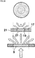
- FIG. 2B is an outline view depicting a light path of the laser light before and after passing through the first phosphor 9 and the second phosphor 21 in the light-emitting device 3 of FIG. 1 , and an outline view depicting a beam profile of the laser light.
- the light having passed through a single phosphor 23 includes blue light (a black portion of a beam profile in FIG. 2A ), yellow light (a dotted portion of the beam profile in FIG. 2A ), and light (a white portion of the beam profile in FIG. 2A ) between the blue light and the yellow light.
- the blue light passes by the optical axis of the condensing lens 7, and enters into the phosphor 23 in a relatively short time and has relatively strong energy.
- the yellow light enters into the phosphor 23 in a relatively long time, progresses obliquely in the phosphor 23, and has relatively weak energy. That is, the light having passed through the phosphor 23 has a color unevenness.
- the white light having passed through the first phosphor 9 has a color unevenness in which a central portion has a strong blue tinge and a peripheral portion has a strong yellow tinge, similarly to the beam profile of FIG. 2A .
- the light having the color unevenness is incident on the second phosphor 21 fitted in the fixing hole 19 of the second accommodation part 17.
- the white light of the central portion which has a short passing distance through the first phosphor 9 and the blue light tinge remains therein, passes through the second phosphor 21, so that it is scattered by the second phosphor 21 and a wavelength thereof is converted. In this way, since the directionality of the white light of the central portion is sufficiently weakened, it is possible to obtain the white light of which the color unevenness is substantially removed.
- the white light of which the color unevenness is substantially removed is reflected by the reflector 60 disposed above the second phosphor 21, and the light reflected by the reflector 60 is illuminated in front of the vehicle through the projection lens 70.
- the first embodiment even when any one of the first phosphor 9 and the second phosphor 21 is separated from the first accommodation part 18 or the second accommodation part 17 or any one of the first phosphor 9 and the second phosphor 21 is damaged and the wavelength conversion function is not normally performed, it is possible to prevent a situation where the laser light emitted from the semiconductor laser element 5 and condensed by the lens 7 is directly illuminated toward the outside of the vehicle by the other phosphor. That is, even when the condensed laser light is not sufficiently illuminated to one phosphor, the laser light is sufficiently illuminated to the other phosphor, so that the other phosphor functions as a fail-safe mechanism. As a result, it is possible to prevent a situation where the condensed laser light is directly illuminated to the outside without passing through the phosphor.
- the reflector 60 it is not necessary to form the reflector 60 with an opening corresponding to the escape hole of the related art. In particular, since it is possible to avoid a situation where a part of the white light passes through an opening of the reflector 60, it is possible to improve the energy efficiency of the lamp 1.
- FIG. 5 is a longitudinal sectional view depicting a vehicle lamp 1A (hereinafter, simply referred to as 'lamp 1A') in accordance with the second embodiment.
- FIG. 3A is a longitudinal sectional view depicting an abnormal state of a light-emitting device 33 in accordance with a second embodiment of the present invention.
- FIG. 3B is a longitudinal sectional view depicting a normal state of the light-emitting device 33 in accordance with the second embodiment.
- the overlapping descriptions of the elements denoted with the same reference numerals as the first illustrative embodiment are omitted.
- the lamp 1A includes a reflector 60A, the projection lens 70, and a light-emitting device 33.
- the reflector 60A, the projection lens 70, and the light-emitting device 33 are respectively disposed in the lamp chamber S formed by the outer cover 80 and the housing 90.
- the light-emitting device 33 includes a semiconductor laser element 35, a condensing lens 37, a phosphor 39 (the first phosphor), a first accommodation part 38, and a second accommodation part 47.
- the semiconductor laser element 35 is a semiconductor light-emitting element configured to emit laser light.
- the condensing lens 37 is configured to condense the laser light emitted from the semiconductor laser element.
- the laser light condensed by the condensing lens 37 is illuminated to the phosphor 39.
- the condensing lens 37 is supported to an inner wall surface (particularly, an inner wall surface extending between the semiconductor laser element 35 and the phosphor 39) of the first accommodation part 38 and is thus fixed to the first accommodation part 38.
- the first accommodation part 38 has a circular cylinder shape and is disposed on a circular plate 41.
- the first accommodation part 38 is configured to accommodate therein the semiconductor laser element 35 and the condensing lens 37.
- a laser accommodation part 43 configured to accommodate therein the semiconductor laser element 35 is accommodated in the first accommodation part 38, and the semiconductor laser element 35 is accommodated in the laser accommodation part 43.
- the laser accommodation part 43 may be formed integrally with the circular plate 11.
- the phosphor 39 is fitted in a fixing hole 45 formed in the first accommodation part 38.
- the phosphor 39 is adhered to an inner wall surface defining the fixing hole 45 by a transparent adhesive such as silicon, low-melting temperature glass or the like, and is thus fixed to the first accommodation part 38.
- the first phosphor 39 and the fixing hole 45 have the same shape, as seen from a plan view.
- the phosphor 39 may be configured as a rectangular or circular plate-shaped member, for example.
- the second accommodation part 47 (laser light discoloring part) is disposed on the circular plate 41 so as to cover the first accommodation part 38. Also, the second accommodation part 47 is disposed between the phosphor 39 and the reflector 60A (in other words, the second accommodation part 47 is disposed at a side opposite to a side of the phosphor 39 facing the condensing lens 37), and is configured so that a part thereof is to be discolored by illumination of the laser light.
- the second accommodation part 47 has a circular cylinder shape, and is configured by a resin material such as an acryl resin, an urethane resin or the like, for example. A gap is formed between the first accommodation part 38 and the second accommodation part 47.
- a characteristic of the resin configuring the second accommodation part 47 is not changed (a color thereof is not changed) by the white light having passed through the phosphor 39 but the resin is discolored by the laser light before passing through the phosphor 39.
- the second accommodation part 47 may also be configured by two or more types of resins.
- the second accommodation part 47 may be configured by a resin material that is not to be discolored by the laser light (the laser light before passing through the phosphor 39), and a laser light discoloring layer (laser light discoloring part) that is to be discolored by the laser light may be formed on a surface of the second accommodation part 47 facing the phosphor 39.
- the laser light discoloring layer is disposed between the phosphor 39 and the reflector, and is configured so that a part thereof is to be discolored by illumination of the laser light.
- the second accommodation part 47 may be configured by a resin material that is to be discolored by the laser light, and a laser light discoloring layer may be formed on a surface of the second accommodation part 47 facing the phosphor 39.
- the phosphor 39, a portion of the second accommodation part 47 facing the phosphor 39, and the laser light discoloring layer may be disposed on an optical axis of the condensing lens 37.
- the material configuring the laser light discoloring layer may be a material that reacts with laser light of a predetermined wavelength band (for example, 700nm to 12000nm) to develop a color.
- a predetermined wavelength band for example, 700nm to 12000nm
- an inorganic material and an organic material are exemplified.
- metal such as iron, zinc, tine, nickel, copper, silver, gold and the like, metal salt such as copper carbonate, nickel carbonate, magnesium nitrate, manganese nitrate, iron nitrate, cadmium nitrate, zinc nitrate, cobalt nitrate, lead nitrate, nickel nitrate and the like, metal hydroxide such as copper hydroxide, aluminum hydroxide, magnesium hydroxide and the like, and metal oxide such as silicon oxide, aluminum oxide, iron oxide and the like can be exemplified.
- organic material fluoran-based, phenothiazine-based and spiropyran-based laser discoloring colorants can be exemplified.
- the second accommodation part 47 is formed of the resin that is discolored by the laser light, it is possible to prevent a situation where the laser light passes through the second accommodation part 47, by a portion discolored by the laser light.
- the second accommodation part 47 may be configured to completely prevent transmission of the laser light or may be configured to remarkably reduce transmissivity of the laser light.
- the second accommodation part 47 is configured by the resin that is to be discolored by the laser light and a laser light discoloring layer is provided on a surface of the second accommodation part 47 facing the phosphor 39, it is possible to more securely prevent a situation where the laser light passes through the second accommodation part 47. Also, even when the second accommodation part 47 is configured by a resin that is not to be discolored by the laser light and a laser light discoloring layer is provided on a surface of the second accommodation part 47 facing the phosphor 39, it is possible to prevent a situation where the laser light passes through the second accommodation part 47.
- the reflector 60A may be formed on its surface with a scattering light forming part 62A configured to scatter the laser light.
- the scattering light forming part 62A may be formed on a surface of the reflector 60A intersecting with the optical axis of the condensing lens 37.
- the laser light having reached the reflector 60A is diffusely reflected by the scattering light forming part 62A.
- the laser light having directionality is converted into the scattering light of low energy by the scattering light forming part 62A, it is possible to prevent a situation where the high-energy laser light is illuminated in front of the vehicle.
- the scattering light forming part 62A may be formed to have an elliptical shape slightly greater than an elliptical shape of the laser light reaching the reflector 60A.
- a curved surface, a concave-convex surface or a diffusing agent formed on the surface of the reflector 60A, an auxiliary phosphor, which is the same as or different from the phosphor 39, or a diffraction grating can be exemplified.
Abstract
Description
- The present invention relates to a vehicle lamp configured to use a semiconductor laser element as a light source, and particularly, to a vehicle lamp including a light-emitting device configured to generate white light by using a semiconductor laser element and a phosphor. Also, the present invention relates to alight-emitting device to be used for the vehicle lamp.
- In a vehicle lamp such as a headlight of an automobile, a laser diode (LD) is tried to be used instead of a light-emitting diode (LED) (refer to Patent Document 1). Since an LD light source has a high light conversion efficiency and a small light-emitting area, it is advantageous to miniaturization of the lamp. In the vehicle lamp configured to use the LD light source, blue laser light is emitted from an LD element to a phosphor, which is a wavelength conversion element. The phosphor is configured to absorb a part of the blue laser light and to emit yellow fluorescence. In this way, the blue laser light and the yellow fluorescence are mixed to generate white light.
- The laser light is high-energy light having high directionality. For this reason, when the laser light is used as the light of a headlight of an automobile, for example, the laser light is converted into the white light suitable for road surface illumination and having appropriate energy by the phosphor, as described above. If the laser light is not sufficiently illuminated to the phosphor, the laser light is reflected on a reflector with high energy, so that the high-energy laser light is illuminated to a pedestrian, a vehicle, a road surface and the like in front thereof. In order to avoid this situation, the phosphor is firmly fixed to an attachment member and is thus securely prevented from being separated and damaged.
- In order to avoid the forward illumination of the high-energy laser light toward the pedestrian and the like, a variety of methods including firmly fixing the phosphor to the attachment member to prevent the phosphor from being separated from the attachment member or being damaged are adopted. However, it cannot be definitely said that it is possible to perfectly avoid an extremely low possibility that the phosphor will be separated from the attachment member. In order to check that the laser light is normally illuminated and scattered to the phosphor (in other words, in order to detect an abnormality of an optical system of the vehicle lamp), a light detector is equipped at a necessary place on a light path, an energy amount of the light (intensity of the light) and a wavelength of the light are measured to check whether the optical system of the vehicle lamp is abnormal by the light detector. If an abnormality is detected and the high-energy laser light is directly reflected by the reflector without being illuminated to the phosphor, it is assumed that the phosphor is separated from the attachment member or is damaged due to a certain cause, and the driving of the laser element is stopped.
- Also, Patent Document 1 discloses a structure where a reflector configured to reflect laser light is formed with a through-hole or an escape hole penetrating the reflector. In Patent Document 1, the laser light escapes to the outside of the reflector when an abnormality occurs, so that the high-energy laser light is prevented from being reflected forward from the reflector.
- Patent Document 1:
JP-A-2014-180886 - However, when there is no light detector, when the light detector is abnormal or when the light detector is not promptly operated, the high-energy laser light may be reflected on the reflector and illuminated forward, as it is.
- Furthermore, when the reflector is formed with the escape hole, a part of the white light reaching the reflector upon the normal operation is wasted. Also, the laser light escapes to the outside of the reflector when an abnormality occurs is reflected to the respective members more than once, so that finally it may be emitted outside of a lamp chamber with high energy.
- Also, in the case of the blue laser light or purple laser light, the light having passed through the phosphor includes the blue light and the like, yellow light and the like and white light. The blue and the like light passes by an optical axis of a lens, enters into the phosphor in a relatively short time and having relatively strong energy. The yellow light and the like progresses obliquely in the phosphor, entering into the phosphor in a relatively long time and having relatively weak energy. The white light to be scattered in all directions. That is, the light having passed through the phosphor has a color unevenness in which a central portion has a strong blue tinge and a peripheral portion has a strong yellow tinge. The light having the color unevenness may not meet chromaticity standards. Further, the light having the color unevenness is reflected by the reflector and is illuminated onto a surface and the like.
- An object of the present invention is to provide a vehicle lamp capable of preventing a situation where laser light emitted from a semiconductor laser element and condensed by a lens is directly illuminated toward an outside of a vehicle, even when a phosphor fixed at a predetermined position is separated or the phosphor cannot perform a normal function. Another object of the present invention is to provide a vehicle lamp capable of solving a color unevenness of light having passed through a phosphor.
- A vehicle lamp in accordance with an aspect of the present invention includes:
- a semiconductor laser element configured to emit laser light;
- a condensing lens configured to condense the laser light emitted from the semiconductor laser element;
- a first phosphor configured to convert a wavelength of at least a part of the laser light condensed by the condensing lens, thereby generating white light;
- a reflector configured to reflect the white light emitted from the first phosphor, and
- a second phosphor disposed between the first phosphor and the reflector and configured to convert a wavelength of at least a part of the light emitted from the first phosphor.
- According to the present invention, it is possible to provide the vehicle lamp capable of preventing a situation where the laser light emitted from the semiconductor laser element and condensed by the lens is directly illuminated toward an outside of a vehicle, even when the phosphor fixed at a predetermined position is separated or the phosphor cannot perform a normal function. Further, it is possible to provide the vehicle lamp capable of solving a color unevenness of the light having passed through the phosphor.
-
-
FIG. 1 is a longitudinal sectional view depicting a light-emitting device in accordance with a first embodiment of the present invention. -
FIG. 2A is an outline view depicting a light path of laser light before and after passing through a phosphor in a light-emitting device having a semiconductor laser element of the related art, and an outline view depicting a beam profile of the laser light. -
FIG. 2B is an outline view depicting a light path of laser light before and after passing through a first phosphor and a second phosphor in the light-emitting device ofFIG. 1 , and an outline view depicting a beam profile of the laser light. -
FIG. 3A is a longitudinal sectional view depicting an abnormal state of a light-emitting device in accordance with a second embodiment of the present invention. -
FIG. 3B is a longitudinal sectional view depicting a normal state of the light-emitting device in accordance with the second embodiment. -
FIG. 4 is a longitudinal sectional view depicting a vehicle lamp in accordance with the first embodiment. -
FIG. 5 is a longitudinal sectional view depicting a vehicle lamp in accordance with the second embodiment. - Hereinafter, a vehicle lamp 1 and a light-
emitting device 3 in accordance with a first embodiment of the present invention will be described with reference toFIGS. 1 ,2A ,2B and4 . - As shown in
FIG. 4 , a vehicle lamp 1 (hereinafter, simply referred to as 'lamp 1') of the first embodiment includes areflector 60, aprojection lens 70, and a light-emitting device 3. Thereflector 60, theprojection lens 70, and the light-emittingdevice 3 are respectively disposed in a lamp chamber S formed by anouter cover 80 and ahousing 90. - The
reflector 60 has a dome shape and is disposed above the light-emitting device 3 so as to cover the light-emitting device 3. Thereflector 60 is configured to reflect light (for example, white light having low directionality generated by afirst phosphor 9 and white light generated by a second phosphor 21) emitted from the light-emittingdevice 3 toward theprojection lens 70. The light-emitting device 3 is disposed at or in the vicinity of a first focus of thereflector 60, and theprojection lens 70 is disposed at or in the vicinity of a second focus of the reflector. The light emitted from the light-emittingdevice 3 is reflected by thereflector 60, and the light reflected by thereflector 60 passes through theprojection lens 70 and is then emitted to an outside (for example, a forward region of a vehicle) of the lamp 1. In this way, a light distribution pattern (for example, a light distribution pattern for low beam) is formed in the forward region of the vehicle. - The
projection lens 70 is made of a transparent resin such as acryl, for example. Theprojection lens 70 is a non-spherical lens of which a front surface-side is a convex surface and a rear surface-side is a planar surface. Theprojection lens 70 may be fixed to a holder or the like. An optical axis of theprojection lens 70 coincides with an optical axis of the lamp 1. - As shown in
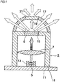
FIG. 1 , the light-emittingdevice 3 includes asemiconductor laser element 5, a condensinglens 7, afirst phosphor 9, afirst accommodation part 18, asecond phosphor 21, and asecond accommodation part 17. - The
semiconductor laser element 5 is a semiconductor light-emitting element configured to emit laser light, and is configured to emit blue laser light of which a light emission peak wavelength is about 450nm or near-ultraviolet laser light of which a light emission peak wavelength is in a near-ultraviolet region (about 405nm), for example. - The
first accommodation part 18 has a circular cylinder shape and is disposed on acircular plate 11. Thefirst accommodation part 18 is configured to accommodate therein thesemiconductor laser element 5 and the condensinglens 7. In particular, alaser accommodation part 13 configured to accommodate therein thesemiconductor laser element 5 is accommodated in thefirst accommodation part 18, and thesemiconductor laser element 5 is accommodated in thelaser accommodation part 13. Thelaser accommodation part 13 may be formed integrally with thecircular plate 11. - The condensing
lens 7 is supported to an inner wall surface (particularly, an inner wall surface extending between thesemiconductor laser element 5 and the first phosphor 9) of thefirst accommodation part 18 and is thus fixed to thefirst accommodation part 18. The condensinglens 7 is disposed at a substantially central portion of thefirst accommodation part 18. Thesemiconductor laser element 5 may be disposed at a position of one focus of the condensinglens 7. Also, thesemiconductor laser element 5, thefirst phosphor 9, and thesecond phosphor 21 may be disposed on an optical axis of the condensinglens 7. The condensinglens 7 is configured to condense the laser light emitted from thesemiconductor laser element 5. The laser light condensed by the condensinglens 7 is illuminated to thefirst phosphor 9. - The
first phosphor 9 is fitted in a fixinghole 15 formed in thefirst accommodation part 18. In particular, thefirst phosphor 9 is adhered to an inner wall surface defining the fixinghole 15 by a transparent adhesive such as silicon, low-melting temperature glass or the like, and is thus fixed to thefirst accommodation part 18. Thefirst phosphor 9 and the fixinghole 15 have the same shape, as seen from a plan view. Thefirst phosphor 9 may be configured as a rectangular or circular plate-shaped member, for example. - The
first phosphor 9 is configured to convert a wavelength of at least a part of the laser light condensed by the condensinglens 7, thereby generating white light. For example, thefirst phosphor 9 is configured to absorb at least a part of blue laser light as excited light, thereby emitting yellow fluorescence. In this way, the blue laser light and the yellow fluorescence are mixed to generate the white light. - The
first phosphor 9 may be configured by a complex body of YAG having an activator such as cerium Ce or the like introduced therein and alumina Al2O3. Thefirst phosphor 9 may be formed as a plate-shaped member having a lower surface and an upper surface aligned in substantially parallel with each other or a layer-shaped member. A thickness of thefirst phosphor 9 may be appropriately selected depending on a desired chromaticity. - The
second accommodation part 17 having a substantial semi-spherical shape is disposed on an upper surface of thefirst accommodation part 18. In particular, a lower end surface of thesecond accommodation part 17 is adhered to a peripheral edge portion of the upper surface of thefirst accommodation part 18. Thesecond accommodation part 17 has a fixinghole 19 having the substantially same shape as the fixinghole 15. - The
second phosphor 21 is fitted in a fixinghole 19 formed in thesecond accommodation part 17. In particular, thesecond phosphor 21 is adhered to an inner wall surface defining the fixinghole 19 by a transparent adhesive such as silicon, low-melting temperature glass or the like, and is thus fixed to thesecond accommodation part 17. Thesecond phosphor 21 and the fixinghole 19 have the same shape, as seen from a plan view. Thesecond phosphor 21 may be configured as a rectangular or circular plate-shaped member, for example. Also, thesecond phosphor 21 may be configured by the same material as thefirst phosphor 9. - The
second phosphor 21 is disposed between thefirst phosphor 9 and thereflector 60 in a direction parallel with the optical axis of the condensing lens 7 (in other words, thesecond phosphor 21 is disposed at a side opposite to a side of thefirst phosphor 9 facing the condensing lens 7). Thesecond phosphor 21 is configured to convert a wavelength of at least a part of the light emitted from thefirst phosphor 9. -
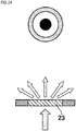
FIG. 2A is an outline view depicting a light path of laser light before and after passing through aphosphor 23 in a light-emitting device having a semiconductor laser element of the related art, and an outline view depicting a beam profile of the laser light.FIG. 2B is an outline view depicting a light path of the laser light before and after passing through thefirst phosphor 9 and thesecond phosphor 21 in the light-emittingdevice 3 ofFIG. 1 , and an outline view depicting a beam profile of the laser light. - As shown in
FIG. 2A , like the related art, the light having passed through asingle phosphor 23 includes blue light (a black portion of a beam profile inFIG. 2A ), yellow light (a dotted portion of the beam profile inFIG. 2A ), and light (a white portion of the beam profile inFIG. 2A ) between the blue light and the yellow light. The blue light passes by the optical axis of the condensinglens 7, and enters into thephosphor 23 in a relatively short time and has relatively strong energy. The yellow light enters into thephosphor 23 in a relatively long time, progresses obliquely in thephosphor 23, and has relatively weak energy. That is, the light having passed through thephosphor 23 has a color unevenness. - In contrast, in the first embodiment, the white light having passed through the
first phosphor 9 has a color unevenness in which a central portion has a strong blue tinge and a peripheral portion has a strong yellow tinge, similarly to the beam profile ofFIG. 2A . The light having the color unevenness is incident on thesecond phosphor 21 fitted in the fixinghole 19 of thesecond accommodation part 17. The white light of the central portion, which has a short passing distance through thefirst phosphor 9 and the blue light tinge remains therein, passes through thesecond phosphor 21, so that it is scattered by thesecond phosphor 21 and a wavelength thereof is converted. In this way, since the directionality of the white light of the central portion is sufficiently weakened, it is possible to obtain the white light of which the color unevenness is substantially removed. - In the first embodiment of
FIGS. 1 and2B , the white light of which the color unevenness is substantially removed is reflected by thereflector 60 disposed above thesecond phosphor 21, and the light reflected by thereflector 60 is illuminated in front of the vehicle through theprojection lens 70. - According to the first embodiment, even when any one of the
first phosphor 9 and thesecond phosphor 21 is separated from thefirst accommodation part 18 or thesecond accommodation part 17 or any one of thefirst phosphor 9 and thesecond phosphor 21 is damaged and the wavelength conversion function is not normally performed, it is possible to prevent a situation where the laser light emitted from thesemiconductor laser element 5 and condensed by thelens 7 is directly illuminated toward the outside of the vehicle by the other phosphor. That is, even when the condensed laser light is not sufficiently illuminated to one phosphor, the laser light is sufficiently illuminated to the other phosphor, so that the other phosphor functions as a fail-safe mechanism. As a result, it is possible to prevent a situation where the condensed laser light is directly illuminated to the outside without passing through the phosphor. - Also, according to the first embodiment, it is not necessary to form the
reflector 60 with an opening corresponding to the escape hole of the related art. In particular, since it is possible to avoid a situation where a part of the white light passes through an opening of thereflector 60, it is possible to improve the energy efficiency of the lamp 1. - In the below, a
vehicle lamp 1A and a light-emittingdevice 33 in accordance with a second embodiment of the present invention will be described with reference toFIGS. 3A ,3B and5. FIG. 5 is a longitudinal sectional view depicting avehicle lamp 1A (hereinafter, simply referred to as 'lamp 1A') in accordance with the second embodiment.FIG. 3A is a longitudinal sectional view depicting an abnormal state of a light-emittingdevice 33 in accordance with a second embodiment of the present invention.FIG. 3B is a longitudinal sectional view depicting a normal state of the light-emittingdevice 33 in accordance with the second embodiment. Meanwhile, in the second embodiment, the overlapping descriptions of the elements denoted with the same reference numerals as the first illustrative embodiment are omitted. - As shown in
FIG. 5A , thelamp 1A includes areflector 60A, theprojection lens 70, and a light-emittingdevice 33. Thereflector 60A, theprojection lens 70, and the light-emittingdevice 33 are respectively disposed in the lamp chamber S formed by theouter cover 80 and thehousing 90. - As shown in
FIG. 3B , the light-emittingdevice 33 includes asemiconductor laser element 35, a condensinglens 37, a phosphor 39 (the first phosphor), afirst accommodation part 38, and asecond accommodation part 47. - The
semiconductor laser element 35 is a semiconductor light-emitting element configured to emit laser light. The condensinglens 37 is configured to condense the laser light emitted from the semiconductor laser element. The laser light condensed by the condensinglens 37 is illuminated to thephosphor 39. The condensinglens 37 is supported to an inner wall surface (particularly, an inner wall surface extending between thesemiconductor laser element 35 and the phosphor 39) of thefirst accommodation part 38 and is thus fixed to thefirst accommodation part 38. - The
first accommodation part 38 has a circular cylinder shape and is disposed on acircular plate 41. Thefirst accommodation part 38 is configured to accommodate therein thesemiconductor laser element 35 and the condensinglens 37. In particular, alaser accommodation part 43 configured to accommodate therein thesemiconductor laser element 35 is accommodated in thefirst accommodation part 38, and thesemiconductor laser element 35 is accommodated in thelaser accommodation part 43. Thelaser accommodation part 43 may be formed integrally with thecircular plate 11. - The
phosphor 39 is fitted in a fixinghole 45 formed in thefirst accommodation part 38. In particular, thephosphor 39 is adhered to an inner wall surface defining the fixinghole 45 by a transparent adhesive such as silicon, low-melting temperature glass or the like, and is thus fixed to thefirst accommodation part 38. Thefirst phosphor 39 and the fixinghole 45 have the same shape, as seen from a plan view. Thephosphor 39 may be configured as a rectangular or circular plate-shaped member, for example. - The second accommodation part 47 (laser light discoloring part) is disposed on the
circular plate 41 so as to cover thefirst accommodation part 38. Also, thesecond accommodation part 47 is disposed between thephosphor 39 and thereflector 60A (in other words, thesecond accommodation part 47 is disposed at a side opposite to a side of thephosphor 39 facing the condensing lens 37), and is configured so that a part thereof is to be discolored by illumination of the laser light. Thesecond accommodation part 47 has a circular cylinder shape, and is configured by a resin material such as an acryl resin, an urethane resin or the like, for example. A gap is formed between thefirst accommodation part 38 and thesecond accommodation part 47. A characteristic of the resin configuring thesecond accommodation part 47 is not changed (a color thereof is not changed) by the white light having passed through thephosphor 39 but the resin is discolored by the laser light before passing through thephosphor 39. In the meantime, thesecond accommodation part 47 may also be configured by two or more types of resins. - In a modified embodiment of the second embodiment, the
second accommodation part 47 may be configured by a resin material that is not to be discolored by the laser light (the laser light before passing through the phosphor 39), and a laser light discoloring layer (laser light discoloring part) that is to be discolored by the laser light may be formed on a surface of thesecond accommodation part 47 facing thephosphor 39. In this case, the laser light discoloring layer is disposed between thephosphor 39 and the reflector, and is configured so that a part thereof is to be discolored by illumination of the laser light. Furthermore, thesecond accommodation part 47 may be configured by a resin material that is to be discolored by the laser light, and a laser light discoloring layer may be formed on a surface of thesecond accommodation part 47 facing thephosphor 39. Thephosphor 39, a portion of thesecond accommodation part 47 facing thephosphor 39, and the laser light discoloring layer may be disposed on an optical axis of the condensinglens 37. - The material configuring the laser light discoloring layer may be a material that reacts with laser light of a predetermined wavelength band (for example, 700nm to 12000nm) to develop a color. As the material, an inorganic material and an organic material are exemplified. As the inorganic material, metal such as iron, zinc, tine, nickel, copper, silver, gold and the like, metal salt such as copper carbonate, nickel carbonate, magnesium nitrate, manganese nitrate, iron nitrate, cadmium nitrate, zinc nitrate, cobalt nitrate, lead nitrate, nickel nitrate and the like, metal hydroxide such as copper hydroxide, aluminum hydroxide, magnesium hydroxide and the like, and metal oxide such as silicon oxide, aluminum oxide, iron oxide and the like can be exemplified. As the organic material, fluoran-based, phenothiazine-based and spiropyran-based laser discoloring colorants can be exemplified.
- In the second embodiment, as shown in
FIG. 3A , even when thephosphor 39 is separated from the fixinghole 45 and thus the high-energy laser light reaches thesecond accommodation part 47, since thesecond accommodation part 47 is formed of the resin that is discolored by the laser light, it is possible to prevent a situation where the laser light passes through thesecond accommodation part 47, by a portion discolored by the laser light. - For example, when the laser light (the blue laser light or purple laser light) condensed by the condensing
lens 37 and having high energy is illuminated to thesecond accommodation part 47, since a portion of the second accommodation part illuminated by the laser light is discolored (for example, blackened), it is possible to prevent a situation where the laser light passes through thesecond accommodation part 47. Here, thesecond accommodation part 47 may be configured to completely prevent transmission of the laser light or may be configured to remarkably reduce transmissivity of the laser light. - Also, when the
second accommodation part 47 is configured by the resin that is to be discolored by the laser light and a laser light discoloring layer is provided on a surface of thesecond accommodation part 47 facing thephosphor 39, it is possible to more securely prevent a situation where the laser light passes through thesecond accommodation part 47. Also, even when thesecond accommodation part 47 is configured by a resin that is not to be discolored by the laser light and a laser light discoloring layer is provided on a surface of thesecond accommodation part 47 facing thephosphor 39, it is possible to prevent a situation where the laser light passes through thesecond accommodation part 47. - Also, in the second embodiment, the
reflector 60A may be formed on its surface with a scatteringlight forming part 62A configured to scatter the laser light. In particular, the scatteringlight forming part 62A may be formed on a surface of thereflector 60A intersecting with the optical axis of the condensinglens 37. In this case, even when a part of the high-energy laser light reaches the surface of thereflector 60A, the laser light having reached thereflector 60A is diffusely reflected by the scatteringlight forming part 62A. In this way, since the laser light having directionality is converted into the scattering light of low energy by the scatteringlight forming part 62A, it is possible to prevent a situation where the high-energy laser light is illuminated in front of the vehicle. - The scattering
light forming part 62A may be formed to have an elliptical shape slightly greater than an elliptical shape of the laser light reaching thereflector 60A. As the scatteringlight forming part 62A, a curved surface, a concave-convex surface or a diffusing agent formed on the surface of thereflector 60A, an auxiliary phosphor, which is the same as or different from thephosphor 39, or a diffraction grating can be exemplified. - Although the embodiments of the present invention have been described, the technical scope of the present invention is not construed to be limited to the embodiments. The embodiments are just exemplary and one skilled in the art can understand that a variety of changes to the embodiments can be made within the scope of the present invention defined in the claims. The technical scope of the present invention is to be determined on the basis of the scope of the present invention defined in the claims and the equivalent scope thereto.
- The subject application is based on a Japanese Patent Application No.
2015-084903 filed on April 17, 2015
Claims (5)
- A vehicle lamp comprising:a semiconductor laser element configured to emit laser light;a condensing lens configured to condense the laser light emitted from the semiconductor laser element;a first phosphor configured to convert a wavelength of at least a part of the laser light condensed by the condensing lens, thereby generating white light;a reflector configured to reflect the white light emitted from the first phosphor; anda second phosphor disposed between the first phosphor and the reflector and configured to convert a wavelength of at least a part of the light emitted from the first phosphor.
- A vehicle lamp comprising:a semiconductor laser element configured to emit laser light;a condensing lens configured to condense the laser light emitted from the semiconductor laser element;a first phosphor configured to convert a wavelength of at least a part of the laser light condensed by the condensing lens, thereby generating white light;a reflector configured to reflect the white light emitted from the first phosphor, anda laser light discoloring part disposed between the first phosphor and the reflector and configured to be partially discolored by illumination of the laser light.
- The vehicle lamp according to claim 2, wherein a surface of the reflector intersecting with an optical axis of the condensing lens is formed with a scattering light forming part configured to scatter the laser light.
- A light-emitting device comprising:a semiconductor laser element configured to emit laser light;a condensing lens configured to condense the laser light emitted from the semiconductor laser element;an accommodation part configured to accommodate therein the semiconductor laser element and the condensing lens;a first phosphor configured to convert a wavelength of at least a part of the laser light condensed by the condensing lens, thereby generating white light, and fixed to the accommodation part; anda second phosphor disposed at a side opposite to a side of the first phosphor facing the condensing lens and configured to convert a wavelength of at least a part of the light emitted from the first phosphor,wherein the first phosphor and the second phosphor are disposed on an optical axis of the condensing lens.
- A light-emitting device comprising:a semiconductor laser element configured to emit laser light;a condensing lens configured to condense the laser light emitted from the semiconductor laser element;a first accommodation part configured to accommodate therein the semiconductor laser element and the condensing lens;a first phosphor configured to convert a wavelength of at least a part of the laser light condensed by the condensing lens, thereby generating white light, and fixed to the first accommodation part; anda laser light discoloring part disposed at a side opposite to a side of the first phosphor facing the condensing lens and configured to be partially discolored by illumination of the laser light,wherein the first phosphor and laser light discoloring part are disposed on an optical axis of the condensing lens.
Applications Claiming Priority (2)
| Application Number | Priority Date | Filing Date | Title |
|---|---|---|---|
| JP2015084903A JP6568706B2 (en) | 2015-04-17 | 2015-04-17 | Vehicle lighting |
| PCT/JP2016/057296 WO2016167056A1 (en) | 2015-04-17 | 2016-03-09 | Vehicle lamp and light-emitting device |
Publications (2)
| Publication Number | Publication Date |
|---|---|
| EP3285000A1 true EP3285000A1 (en) | 2018-02-21 |
| EP3285000A4 EP3285000A4 (en) | 2019-05-01 |
Family
ID=57126164
Family Applications (1)
| Application Number | Title | Priority Date | Filing Date |
|---|---|---|---|
| EP16779848.7A Withdrawn EP3285000A4 (en) | 2015-04-17 | 2016-03-09 | Vehicle lamp and light-emitting device |
Country Status (5)
| Country | Link |
|---|---|
| US (1) | US20180094788A1 (en) |
| EP (1) | EP3285000A4 (en) |
| JP (1) | JP6568706B2 (en) |
| CN (1) | CN108307646B (en) |
| WO (1) | WO2016167056A1 (en) |
Cited By (1)
| Publication number | Priority date | Publication date | Assignee | Title |
|---|---|---|---|---|
| EP3636993A1 (en) * | 2018-10-08 | 2020-04-15 | Automotive Lighting Reutlingen GmbH | Illumination device for a motor vehicle and motor vehicle with same |
Families Citing this family (11)
| Publication number | Priority date | Publication date | Assignee | Title |
|---|---|---|---|---|
| AT518010B1 (en) * | 2015-10-23 | 2017-10-15 | Zkw Group Gmbh | Monitoring device for monitoring the operating state of a laser vehicle headlight and vehicle headlights |
| DE102017101008A1 (en) * | 2017-01-19 | 2018-07-19 | Osram Gmbh | MODULE, SET OF POSITIONING ELEMENTS, ARRANGEMENT WITH A MODULE, HEADLIGHTS AND METHOD FOR MANUFACTURING A MODULE |
| DE102017117027B3 (en) * | 2017-07-27 | 2018-12-13 | SMR Patents S.à.r.l. | Projection device, review device and motor vehicle |
| EP3756250B1 (en) * | 2018-02-20 | 2022-01-12 | Lumileds LLC | Light converting device with confined light converter |
| US11231569B2 (en) * | 2018-06-13 | 2022-01-25 | Panasonic Corporation | Light-emitting device and illumination device |
| CN109027950A (en) * | 2018-07-27 | 2018-12-18 | 华域视觉科技(上海)有限公司 | A kind of headlight for vehicles and its laser assisted distance light mould group and laser safety detection device |
| WO2020019396A1 (en) * | 2018-07-27 | 2020-01-30 | 华域视觉科技(上海)有限公司 | Automobile headlamp and laser-assisted distance light module therefor, and laser safety testing apparatus |
| CN109578823B (en) * | 2018-12-17 | 2020-02-14 | 华中科技大学 | Laser white light source with laser diode and fluorescent powder film cooled simultaneously |
| JP7308083B2 (en) * | 2019-06-26 | 2023-07-13 | 株式会社小糸製作所 | vehicle lamp |
| CN111076140A (en) * | 2019-12-31 | 2020-04-28 | 华域视觉科技(上海)有限公司 | Illumination detection module |
| US11603975B1 (en) | 2022-01-28 | 2023-03-14 | Toyota Motor Engineering & Manufacturing North America, Inc. | Dynamic adjustment of forward lighting projection lens using photochromatic material |
Family Cites Families (10)
| Publication number | Priority date | Publication date | Assignee | Title |
|---|---|---|---|---|
| JP4546176B2 (en) * | 2004-07-16 | 2010-09-15 | 京セラ株式会社 | Light emitting device |
| JP2006135002A (en) * | 2004-11-04 | 2006-05-25 | Koito Mfg Co Ltd | Light-emitting device and lighting fixture for car |
| JP5083205B2 (en) * | 2006-03-10 | 2012-11-28 | 日亜化学工業株式会社 | Light emitting device |
| EP2461090B1 (en) * | 2010-12-01 | 2020-07-01 | Stanley Electric Co., Ltd. | Vehicle light |
| JP5657357B2 (en) * | 2010-12-01 | 2015-01-21 | スタンレー電気株式会社 | Vehicle lighting |
| WO2012121304A1 (en) * | 2011-03-08 | 2012-09-13 | 三菱化学株式会社 | Light-emitting device, and lighting device equipped with light-emitting device |
| JP6164518B2 (en) * | 2013-03-18 | 2017-07-19 | スタンレー電気株式会社 | Vehicle headlamp |
| US9142733B2 (en) * | 2013-09-03 | 2015-09-22 | Panasonic Intellectual Property Management Co., Ltd. | Light source device including a high energy light source and a wavelength conversion member, illuminating device comprising the same, and vehicle |
| WO2015098258A1 (en) * | 2013-12-25 | 2015-07-02 | シャープ株式会社 | Light-emitting device |
| JP5780325B2 (en) * | 2014-02-26 | 2015-09-16 | カシオ計算機株式会社 | Light source device and projector |
-
2015
- 2015-04-17 JP JP2015084903A patent/JP6568706B2/en active Active
-
2016
- 2016-03-09 US US15/566,789 patent/US20180094788A1/en not_active Abandoned
- 2016-03-09 EP EP16779848.7A patent/EP3285000A4/en not_active Withdrawn
- 2016-03-09 WO PCT/JP2016/057296 patent/WO2016167056A1/en active Application Filing
- 2016-03-09 CN CN201680022062.XA patent/CN108307646B/en active Active
Cited By (1)
| Publication number | Priority date | Publication date | Assignee | Title |
|---|---|---|---|---|
| EP3636993A1 (en) * | 2018-10-08 | 2020-04-15 | Automotive Lighting Reutlingen GmbH | Illumination device for a motor vehicle and motor vehicle with same |
Also Published As
| Publication number | Publication date |
|---|---|
| JP6568706B2 (en) | 2019-08-28 |
| EP3285000A4 (en) | 2019-05-01 |
| US20180094788A1 (en) | 2018-04-05 |
| JP2016207330A (en) | 2016-12-08 |
| CN108307646A (en) | 2018-07-20 |
| WO2016167056A1 (en) | 2016-10-20 |
| CN108307646B (en) | 2021-04-23 |
Similar Documents
| Publication | Publication Date | Title |
|---|---|---|
| EP3285000A1 (en) | Vehicle lamp and light-emitting device | |
| US9970619B2 (en) | Vehicle lamp | |
| CN106051576B (en) | Vehicle lamp | |
| KR102154645B1 (en) | Vehicle headlight | |
| US9803832B2 (en) | Lighting device with a phosphor body spaced apart from a light source | |
| EP2461090B1 (en) | Vehicle light | |
| US9261259B2 (en) | Laser-beam utilization device and vehicle headlight | |
| JP5212785B2 (en) | Vehicle headlamp | |
| EP2461092B1 (en) | Vehicle light | |
| CN106164575B (en) | Lighting device with light source and spaced apart luminaries | |
| EP3627037B1 (en) | Vehicular lamp | |
| JP2015146396A (en) | Light emitting device, vehicle lamp fitting and vehicle illuminating device | |
| US20150070929A1 (en) | Lighting device having a reflector, lens, and aperture | |
| JP5647499B2 (en) | Vehicle lighting | |
| CN109751564B (en) | Phosphor module | |
| EP3421879A1 (en) | Led lamp | |
| CN111197725A (en) | Lighting device and lamp |
Legal Events
| Date | Code | Title | Description |
|---|---|---|---|
| PUAI | Public reference made under article 153(3) epc to a published international application that has entered the european phase |
Free format text: ORIGINAL CODE: 0009012 |
|
| 17P | Request for examination filed |
Effective date: 20171012 |
|
| AK | Designated contracting states |
Kind code of ref document: A1 Designated state(s): AL AT BE BG CH CY CZ DE DK EE ES FI FR GB GR HR HU IE IS IT LI LT LU LV MC MK MT NL NO PL PT RO RS SE SI SK SM TR |
|
| AX | Request for extension of the european patent |
Extension state: BA ME |
|
| DAV | Request for validation of the european patent (deleted) | ||
| DAX | Request for extension of the european patent (deleted) | ||
| RIC1 | Information provided on ipc code assigned before grant |
Ipc: F21S 8/10 20181130AFI20161024BHEP Ipc: F21Y 115/10 20160101ALI20161024BHEP |
|
| RIC1 | Information provided on ipc code assigned before grant |
Ipc: F21Y 115/30 20160101ALN20181213BHEP Ipc: F21S 41/176 20180101ALI20181213BHEP Ipc: F21S 41/16 20180101AFI20181213BHEP |
|
| RIC1 | Information provided on ipc code assigned before grant |
Ipc: F21S 41/176 20180101ALI20181213BHEP Ipc: F21Y 115/30 20160101ALN20181213BHEP Ipc: F21S 41/16 20180101AFI20181213BHEP |
|
| A4 | Supplementary search report drawn up and despatched |
Effective date: 20190403 |
|
| RIC1 | Information provided on ipc code assigned before grant |
Ipc: F21Y 115/30 20160101ALN20190328BHEP Ipc: F21S 41/16 20180101AFI20190328BHEP Ipc: F21S 41/176 20180101ALI20190328BHEP |
|
| STAA | Information on the status of an ep patent application or granted ep patent |
Free format text: STATUS: THE APPLICATION HAS BEEN WITHDRAWN |
|
| 18W | Application withdrawn |
Effective date: 20210113 |