EP3284969A1 - Vibration-damping device - Google Patents
Vibration-damping device Download PDFInfo
- Publication number
- EP3284969A1 EP3284969A1 EP16827744.0A EP16827744A EP3284969A1 EP 3284969 A1 EP3284969 A1 EP 3284969A1 EP 16827744 A EP16827744 A EP 16827744A EP 3284969 A1 EP3284969 A1 EP 3284969A1
- Authority
- EP
- European Patent Office
- Prior art keywords
- center
- coupling shaft
- vibration damping
- damping device
- restoring force
- Prior art date
- Legal status (The legal status is an assumption and is not a legal conclusion. Google has not performed a legal analysis and makes no representation as to the accuracy of the status listed.)
- Withdrawn
Links
Images







Classifications
-
- F—MECHANICAL ENGINEERING; LIGHTING; HEATING; WEAPONS; BLASTING
- F16—ENGINEERING ELEMENTS AND UNITS; GENERAL MEASURES FOR PRODUCING AND MAINTAINING EFFECTIVE FUNCTIONING OF MACHINES OR INSTALLATIONS; THERMAL INSULATION IN GENERAL
- F16F—SPRINGS; SHOCK-ABSORBERS; MEANS FOR DAMPING VIBRATION
- F16F15/00—Suppression of vibrations in systems; Means or arrangements for avoiding or reducing out-of-balance forces, e.g. due to motion
- F16F15/10—Suppression of vibrations in rotating systems by making use of members moving with the system
- F16F15/14—Suppression of vibrations in rotating systems by making use of members moving with the system using masses freely rotating with the system, i.e. uninvolved in transmitting driveline torque, e.g. rotative dynamic dampers
- F16F15/1407—Suppression of vibrations in rotating systems by making use of members moving with the system using masses freely rotating with the system, i.e. uninvolved in transmitting driveline torque, e.g. rotative dynamic dampers the rotation being limited with respect to the driving means
- F16F15/145—Masses mounted with play with respect to driving means thus enabling free movement over a limited range
-
- F—MECHANICAL ENGINEERING; LIGHTING; HEATING; WEAPONS; BLASTING
- F16—ENGINEERING ELEMENTS AND UNITS; GENERAL MEASURES FOR PRODUCING AND MAINTAINING EFFECTIVE FUNCTIONING OF MACHINES OR INSTALLATIONS; THERMAL INSULATION IN GENERAL
- F16F—SPRINGS; SHOCK-ABSORBERS; MEANS FOR DAMPING VIBRATION
- F16F15/00—Suppression of vibrations in systems; Means or arrangements for avoiding or reducing out-of-balance forces, e.g. due to motion
- F16F15/10—Suppression of vibrations in rotating systems by making use of members moving with the system
- F16F15/14—Suppression of vibrations in rotating systems by making use of members moving with the system using masses freely rotating with the system, i.e. uninvolved in transmitting driveline torque, e.g. rotative dynamic dampers
-
- F—MECHANICAL ENGINEERING; LIGHTING; HEATING; WEAPONS; BLASTING
- F16—ENGINEERING ELEMENTS AND UNITS; GENERAL MEASURES FOR PRODUCING AND MAINTAINING EFFECTIVE FUNCTIONING OF MACHINES OR INSTALLATIONS; THERMAL INSULATION IN GENERAL
- F16F—SPRINGS; SHOCK-ABSORBERS; MEANS FOR DAMPING VIBRATION
- F16F15/00—Suppression of vibrations in systems; Means or arrangements for avoiding or reducing out-of-balance forces, e.g. due to motion
- F16F15/10—Suppression of vibrations in rotating systems by making use of members moving with the system
- F16F15/14—Suppression of vibrations in rotating systems by making use of members moving with the system using masses freely rotating with the system, i.e. uninvolved in transmitting driveline torque, e.g. rotative dynamic dampers
- F16F15/1407—Suppression of vibrations in rotating systems by making use of members moving with the system using masses freely rotating with the system, i.e. uninvolved in transmitting driveline torque, e.g. rotative dynamic dampers the rotation being limited with respect to the driving means
- F16F15/1464—Masses connected to driveline by a kinematic mechanism or gear system
- F16F15/1471—Masses connected to driveline by a kinematic mechanism or gear system with a kinematic mechanism, i.e. linkages, levers
-
- F—MECHANICAL ENGINEERING; LIGHTING; HEATING; WEAPONS; BLASTING
- F16—ENGINEERING ELEMENTS AND UNITS; GENERAL MEASURES FOR PRODUCING AND MAINTAINING EFFECTIVE FUNCTIONING OF MACHINES OR INSTALLATIONS; THERMAL INSULATION IN GENERAL
- F16F—SPRINGS; SHOCK-ABSORBERS; MEANS FOR DAMPING VIBRATION
- F16F15/00—Suppression of vibrations in systems; Means or arrangements for avoiding or reducing out-of-balance forces, e.g. due to motion
- F16F15/30—Flywheels
- F16F15/31—Flywheels characterised by means for varying the moment of inertia
-
- F—MECHANICAL ENGINEERING; LIGHTING; HEATING; WEAPONS; BLASTING
- F16—ENGINEERING ELEMENTS AND UNITS; GENERAL MEASURES FOR PRODUCING AND MAINTAINING EFFECTIVE FUNCTIONING OF MACHINES OR INSTALLATIONS; THERMAL INSULATION IN GENERAL
- F16D—COUPLINGS FOR TRANSMITTING ROTATION; CLUTCHES; BRAKES
- F16D3/00—Yielding couplings, i.e. with means permitting movement between the connected parts during the drive
- F16D3/02—Yielding couplings, i.e. with means permitting movement between the connected parts during the drive adapted to specific functions
- F16D3/12—Yielding couplings, i.e. with means permitting movement between the connected parts during the drive adapted to specific functions specially adapted for accumulation of energy to absorb shocks or vibration
-
- F—MECHANICAL ENGINEERING; LIGHTING; HEATING; WEAPONS; BLASTING
- F16—ENGINEERING ELEMENTS AND UNITS; GENERAL MEASURES FOR PRODUCING AND MAINTAINING EFFECTIVE FUNCTIONING OF MACHINES OR INSTALLATIONS; THERMAL INSULATION IN GENERAL
- F16F—SPRINGS; SHOCK-ABSORBERS; MEANS FOR DAMPING VIBRATION
- F16F2228/00—Functional characteristics, e.g. variability, frequency-dependence
- F16F2228/001—Specific functional characteristics in numerical form or in the form of equations
-
- F—MECHANICAL ENGINEERING; LIGHTING; HEATING; WEAPONS; BLASTING
- F16—ENGINEERING ELEMENTS AND UNITS; GENERAL MEASURES FOR PRODUCING AND MAINTAINING EFFECTIVE FUNCTIONING OF MACHINES OR INSTALLATIONS; THERMAL INSULATION IN GENERAL
- F16F—SPRINGS; SHOCK-ABSORBERS; MEANS FOR DAMPING VIBRATION
- F16F2232/00—Nature of movement
- F16F2232/02—Rotary
-
- F—MECHANICAL ENGINEERING; LIGHTING; HEATING; WEAPONS; BLASTING
- F16—ENGINEERING ELEMENTS AND UNITS; GENERAL MEASURES FOR PRODUCING AND MAINTAINING EFFECTIVE FUNCTIONING OF MACHINES OR INSTALLATIONS; THERMAL INSULATION IN GENERAL
- F16H—GEARING
- F16H45/00—Combinations of fluid gearings for conveying rotary motion with couplings or clutches
- F16H45/02—Combinations of fluid gearings for conveying rotary motion with couplings or clutches with mechanical clutches for bridging a fluid gearing of the hydrokinetic type
- F16H2045/0221—Combinations of fluid gearings for conveying rotary motion with couplings or clutches with mechanical clutches for bridging a fluid gearing of the hydrokinetic type with damping means
- F16H2045/0226—Combinations of fluid gearings for conveying rotary motion with couplings or clutches with mechanical clutches for bridging a fluid gearing of the hydrokinetic type with damping means comprising two or more vibration dampers
-
- F—MECHANICAL ENGINEERING; LIGHTING; HEATING; WEAPONS; BLASTING
- F16—ENGINEERING ELEMENTS AND UNITS; GENERAL MEASURES FOR PRODUCING AND MAINTAINING EFFECTIVE FUNCTIONING OF MACHINES OR INSTALLATIONS; THERMAL INSULATION IN GENERAL
- F16H—GEARING
- F16H45/00—Combinations of fluid gearings for conveying rotary motion with couplings or clutches
- F16H45/02—Combinations of fluid gearings for conveying rotary motion with couplings or clutches with mechanical clutches for bridging a fluid gearing of the hydrokinetic type
- F16H2045/0221—Combinations of fluid gearings for conveying rotary motion with couplings or clutches with mechanical clutches for bridging a fluid gearing of the hydrokinetic type with damping means
- F16H2045/0263—Combinations of fluid gearings for conveying rotary motion with couplings or clutches with mechanical clutches for bridging a fluid gearing of the hydrokinetic type with damping means the damper comprising a pendulum
Definitions
- the invention according to the present disclosure relates to a vibration damping device that damps vibration of a rotary element.
- a damper that includes: a link mechanism that includes a first link serving as a crank member coupled to a crankshaft and a second link serving as a connecting rod coupled to the first link; and an annular inertial body coupled to the second link and coupled so as to be turnable by a predetermined angle relative to the crankshaft via the link mechanism (see Patent Document 1, for example).
- the point of coupling between the crankshaft and the first link is spaced away in the circumferential direction from the point of coupling between the inertial body and the second link, and a mass body is formed on the first link.
- the first link and the second link of the link mechanism operate to keep a state in which the first link and the second link are balanced with respective centrifugal forces that act thereon when the crankshaft is rotated. Therefore, a force (a force in the rotational direction) that acts to keep the link mechanism in an equilibrium state (balanced state) acts on the inertial body, and such a force causes the inertial body to make motion that is generally similar to that made when the inertial body is coupled to a rotary shaft via a spring member. Consequently, with the link mechanism functioning as a spring member and with the inertial body functioning as a mass body, twisting vibration caused in the crankshaft is reduced.
- Patent Document 1 Japanese Patent Application Publication No. 2001-263424 ( JP 2001-263424 A )
- the equivalent rigidity K of the damper depends on a restoring force that acts to return the first and second links to their positions in the equilibrium state, that is, a component force of a centrifugal force that acts mainly on the first link. In the damper described in Patent Document 1, however, the component force of the centrifugal force is zero at the center of the swing range (see the broken line in FIG.
- the present disclosure provides a vibration damping device that includes: a support member that rotates together with a rotary element, to which torque from an engine is transferred, about a center of rotation of the rotary element; a restoring force generation member that is coupled to the support member via a coupling shaft and that is swingable about the coupling shaft along with rotation of the support member; and an inertial mass body coupled to the support member via the restoring force generation member and swung about the center of rotation in conjunction with the restoring force generation member along with rotation of the support member, the vibration damping device damping vibration of the rotary element, in which when the support member is rotated, a component force of a centrifugal force that acts on the restoring force generation member along with rotation of the support member in a direction that is orthogonal to a direction from a center of the coupling shaft toward a center of gravity of the restoring force generation member always acts on the restoring force generation member as a restoring force that acts to return the inertial mass body to a center of a swing range
- a component force of a centrifugal force that acts on the restoring force generation member along with rotation of the support member in a direction that is orthogonal to the direction from the center of the coupling shaft toward the center of gravity of the restoring force generation member acts as a restoring force (moment) that acts to return the inertial mass body to the center of the swing range.
- the component force is maximum when the inertial mass body is positioned at the center of the swing range.
- the restoring force for the same centrifugal force which acts on the restoring force generation member can be increased over the entire swing range of the restoring force generation member compared to a case where the component force of the centrifugal force which acts on the restoring force generation member in a direction that is orthogonal to the direction from the center of the coupling shaft toward the center of gravity of the restoring force generation member is zero when the inertial mass body is positioned at the center of the swing range.
- the vibration damping device it is possible to increase the equivalent rigidity of the vibration damping device while suppressing an increase in weight of the restoring force generation member, which can improve the degree of freedom in setting of the equivalent rigidity and the equivalent mass, that is, the vibration order. As a result, it is possible to further improve the vibration damping performance while suppressing an increase in weight or size of the restoring force generation member and hence the entire device.
- FIG. 1 is a schematic diagram illustrating a starting device 1 that includes a vibration damping device 20 according to the present disclosure.
- the starting device 1 illustrated in the drawing is mounted on a vehicle that includes an engine (internal combustion engine) EG that serves as a drive device (motor), for example.
- engine internal combustion engine
- the starting device 1 includes: a front cover 3 that serves as an input member coupled to a crankshaft of the engine EG; a pump impeller (input-side fluid transmission element) 4 fixed to the front cover 3 to rotate together with the front cover 3; a turbine runner (output-side fluid transmission element) 5 that is rotatable coaxially with the pump impeller 4; a damper hub 7 that serves as an output member fixed to an input shaft IS of a transmission (power transfer device) TM that is an automatic transmission (AT), a continuously variable transmission (CVT), a dual clutch transmission (DCT), a hybrid transmission, or a speed reducer; a lock-up clutch 8 that is a hydraulic single-plate clutch, for example; a damper device 10; and so forth.
- a transmission power transfer device
- TM that is an automatic transmission (AT), a continuously variable transmission (CVT), a dual clutch transmission (DCT), a hybrid transmission, or a speed reducer
- a lock-up clutch 8 that is a hydraulic single-
- the term “axial direction” basically indicates the direction of extension of the center axis (axis) of the starting device 1 or the damper device 10 (vibration damping device 20).
- the term “radial direction” basically indicates the radial direction of the starting device 1, the damper device 10, or a rotary element of the damper device 10 etc., that is, the direction of extension of a line that extends in directions (radial directions) that are orthogonal to the center axis of the starting device 1 or the damper device 10 from the center axis.
- circumferential direction basically indicates the circumferential direction of the starting device 1, the damper device 10, or a rotary element of the damper device 10 etc., that is, a direction along the rotational direction of such a rotary element.
- the pump impeller 4 has a pump shell (not illustrated) tightly fixed to the front cover 3, and a plurality of pump blades (not illustrated) disposed on the inner surface of the pump shell.
- the turbine runner 5 has a turbine shell (not illustrated), and a plurality of turbine blades (not illustrated) disposed on the inner surface of the turbine shell.
- the inner peripheral portion of the turbine shell is fixed to the damper hub 7 via a plurality of rivets.
- the pump impeller 4 and the turbine runner 5 face each other.
- a stator 6 is disposed between and coaxially with the pump impeller 4 and the turbine runner 5.
- the stator 6 adjusts a flow of working oil (working fluid) from the turbine runner 5 to the pump impeller 4.
- the stator 6 has a plurality of stator blades (not illustrated).
- the rotational direction of the stator 6 is set to only one direction by a one-way clutch 61.
- the pump impeller 4, the turbine runner 5, and the stator 6 form a torus (annular flow passage) that allows circulation of working oil, and function as a torque converter (fluid transmission apparatus) with a torque amplification function. It should be noted, however, that the stator 6 and the one-way clutch 61 may be omitted from the starting device 1, and that the pump impeller 4 and the turbine runner 5 may function as a fluid coupling.
- the lock-up clutch 8 can establish and release lock-up in which the front cover 3 and the damper hub 7 are coupled to each other via the damper device 10.
- the lock-up clutch 8 is constituted as a hydraulic single-plate clutch, and has a lock-up piston 80 (not illustrated) disposed inside the front cover 3 and in the vicinity of the inner wall surface of the front cover 3 on the engine EG side and fitted so as to be movable in the axial direction with respect to the damper hub 7.
- a friction material is affixed to surfaces of the lock-up piston 80 on the outer peripheral side and on the front cover 3 side.
- a lock-up chamber (not illustrated) is defined between the lock-up piston 80 and the front cover 3.
- the lock-up chamber is connected to a hydraulic control device (not illustrated) via a working oil supply passage and an oil passage formed in the input shaft IS.
- a hydraulic multi-plate clutch that includes at least one friction engagement plate (a plurality of friction materials) may be adopted as the lock-up clutch 8.
- the damper device 10 includes, as rotary elements, an annular drive member (input element) 11 coupled to the lock-up piston 80 of the lock-up clutch 8 so as to rotate therewith, and an annular driven member (output element) 15 coupled to the input shaft IS of the transmission TM.
- the damper device 10 also includes a plurality of (e.g. four in the present embodiment) springs (elastic bodies) SP disposed at intervals in the circumferential direction on the same circumference.
- Arc coil springs which are made of a metal material wound so as to have an axis that extends arcuately when no load is applied, or straight coil springs, which are made of a metal material spirally wound so as to have an axis that extends straight when no load is applied, are adopted as the springs SP.
- so-called double springs may be adopted as the springs SP.
- the drive member 11, which is an input element of the damper device 10, includes: an annular first input plate member disposed in proximity to the lock-up piston 80 (front cover 3); and an annular second input plate member disposed close to the pump impeller 4 and the turbine runner 5 and away from the lock-up piston 80 with respect to the first input plate member and coupled to the first input plate member via a plurality of rivets (neither of which is illustrated).
- the first input plate member is rotatably supported by the damper hub 7, and coupled to the lock-up piston 80 so as to rotate therewith.
- the first input plate member has: a plurality of (e.g. four in the present embodiment) outer spring support portions that support (guide) the outer peripheral portions of the associated springs SP from the front cover 3 (engine EG) side; a plurality of (e.g. four in the present embodiment) inner spring support portions that support (guide) the inner peripheral portions of the associated springs SP from the front cover 3 side; and a plurality of (e.g. four in the present embodiment) spring abutment portions (none of which is illustrated).
- the second input plate member has: a plurality of (e.g.
- outer spring support portions that support (guide) the outer peripheral portions of the associated springs SP from the turbine runner 5 (transmission TM) side; a plurality of (e.g. four in the present embodiment) inner spring support portions that support (guide) the inner peripheral portions of the associated springs SP from the turbine runner 5 side; and a plurality of (e.g. four in the present embodiment) spring abutment portions (none of which is illustrated).
- the outer spring support portions of the first input plate member face the respective outer spring support portions of the second input plate member
- the inner spring support portions of the first input plate member face the respective inner spring support portions of the second input plate member.
- the springs SP are supported by the first and second input plate members which constitute the drive member 11, and are arranged at intervals (equal intervals) in the circumferential direction in the vicinity of the inner peripheral portion of the turbine shell, for example. With the damper device 10 in the attached state, in addition, the spring abutment portions of the first and second input plate members are provided between the springs SP which are adjacent to each other to abut against the end portions of such springs SP.
- the driven member 15 is disposed between the first input plate member and the second input plate member of the drive member 11, and fixed to the damper hub 7 together with the turbine shell of the turbine runner 5 via a plurality of rivets or by welding. Consequently, the driven member 15 is coupled to the input shaft IS of the transmission TM via the damper hub 7.
- the driven member 15 has a plurality of (e.g. four in the present embodiment) spring abutment portions (not illustrated) that can abut against the end portions of the associated springs SP. With the damper device 10 in the attached state, the spring abutment portions of the driven member 15 are provided between the springs SP which are adjacent to each other to abut against the end portions of such springs SP. Consequently, the driven member 15 is coupled to the drive member 11 via the plurality of springs SP which act in parallel with each other.
- the vibration damping device 20 is coupled to the driven member 15 of the damper device 10, and disposed inside the fluid transmission chamber 9 which is filled with working oil.
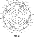
- the vibration damping device 20 includes: the driven member 15 which serves as a support member (first link); a plurality of (e.g. four in the present embodiment) crank members 22 that serve as a restoring force generation member (second link); a plurality of (e.g. a total of eight in the present embodiment) connecting rods 23 that serve as a connecting member (third link); and a single annular inertial mass body (fourth link) 24.
- the driven member 15 has a plurality of (e.g. four in the present embodiment) projecting support portions 151 formed at intervals (equal intervals) in the circumferential direction to project radially outward from the outer periphery of the driven member 15.
- a first end portion of each crank member 22 is rotatably coupled to a corresponding one of the projecting support portions 151 of the driven member 15.
- each of the crank members 22 has two plate members 220.
- the plate members 220 are formed from a metal plate so as to have an arcuate planar shape, and the radius of curvature of the outer peripheral edges of the plate members 220 is determined to be the same as the radius of curvature of the outer peripheral edge of the inertial mass body 24.
- the two plate members 220 face each other in the axial direction of the damper device 10 via the associated projecting support portion 151 and the inertial mass body 24, and are coupled to each other via a first coupling shaft A1.
- the first coupling shaft A1 is inserted through a coupling hole (circular hole) formed in the projecting support portion 151 of the driven member 15, and both end portions of the first coupling shaft A1 are supported by first end portions of the associated plate members 220. Consequently, each of the crank members 22 (two plate members 220) is coupled (pinned) to the driven member 15 so as to be rotatable, that is, swingable, about the first coupling shaft A1.
- a bearing such as a ball bearing may be disposed in at least one of a space between the plate members 220 and the first coupling shaft A1 and a space between the projecting support portion 151 and the first coupling shaft A1.
- Each of the connecting rods 23 is formed from a metal plate to be narrow in width. As illustrated in FIG. 4 , two connecting rods 23 are provided for each of the crank members 22. That is, one connecting rod 23 is interposed between one of the plate members 220 that constitute the crank member 22 and the inertial mass body 24 in the axial direction, and one connecting rod 23 is interposed between the other plate member 220 that constitute the crank member 22 and the inertial mass body 24 in the axial direction.
- a first end (end portion on the radially outer side) of each connecting rod 23 is rotatably coupled (pinned) to a corresponding one of the plate members 220 via a second coupling shaft A2.
- the second coupling shaft A2 is disposed such that the center thereof extends coaxially with a line that passes through a center of gravity G of the crank member 22 (around the center portion of the plate member 220 in the longitudinal direction). Consequently, the length from the center of the first coupling shaft A1, which couples the driven member 15 (projecting support portion 151) and the crank member 22 to each other, to the center of gravity G of the crank member 22 coincides with the length (interaxial distance) from the center of the first coupling shaft A1 to the center of the second coupling shaft A2, which couples the crank member 22 and the connecting rod 23 to each other.
- crank member 22 (plate members 220) is positioned on the opposite side of the second coupling shaft A2 from the first coupling shaft A1.
- a bearing such as a ball bearing may be disposed in at least one of a space between the plate members 220 and the second coupling shaft A2 and a space between the connecting rods 23 and the second coupling shaft A2.
- the inertial mass body 24 is an annular member formed from a metal plate. As illustrated in FIGS. 2 to 4 , the inertial mass body 24 has: a short cylindrical (annular) main body 240; and a plurality of (e.g. four in the present embodiment) projecting portions 241 provided at intervals (equal intervals) in the circumferential direction to project radially inward from the inner peripheral surface of the main body 240.
- the weight of the inertial mass body 24 is determined to be sufficiently larger than the weight of one crank member 22, and to be sufficiently larger than the weight of one connecting rod 23. As illustrated in FIG.
- the projecting portions 241 of the inertial mass body 24 are disposed away from the projecting support portions 151 of the driven member 15 in the circumferential direction, and each held by two connecting rods 23 from both sides in the axial direction.
- each of the projecting portions 241 has a coupling hole (circular hole), and rotatably coupled (pinned) to second ends of (end portions on the radially inner side) of the two connecting rods 23 on both sides via a third coupling shaft A3 inserted through the coupling hole. Consequently, the inertial mass body 24 is coupled to the driven member 15 which serves as the support member via the plurality of connecting rods 23 and the plurality of crank members 22.
- a bearing such as a ball bearing may be disposed in at least one of a space between the connecting rods 23 and the third coupling shaft A3 and a space between the projecting portion 241 and the third coupling shaft A3.
- the inner peripheral surface of the main body 240 of the inertial mass body 24 is in sliding contact with the outer peripheral surfaces of the projecting support portions 151 of the driven member 15, and the inner peripheral surfaces of the projecting portions 241 of the inertial mass body 24 are in sliding contact with portions of an outer peripheral surface 152 of the driven member 15 between the projecting support portions 151 which are adjacent to each other. Consequently, the inertial mass body 24 which is annular is supported (aligned) by the driven member 15 such that the center of the inertial mass body 24 coincides with a center of rotation RC of the driven member 15 which is fixed to the damper hub 7, and is rotatable about the center of rotation RC.
- the vibration damping device 20 compact by rotatably supporting the inertial mass body 24 using the driven member 15 (support member) in this way.
- the driven member 15 support member
- the driven member 15, which serves as the first link (rotary element) which is rotated by power from the engine EG, and the crank member 22, which is rotatably coupled to the driven member 15, constitute a turning pair.
- the crank member 22 and the connecting rods 23, which are rotatably coupled to the crank member 22, constitute a turning pair.
- the inertial mass body 24 is rotatably coupled to the connecting rods 23 to constitute a turning pair with the connecting rods 23, and rotatably supported by the driven member 15 to constitute a turning pair with the driven member 15. That is, the driven member 15, the crank members 22, the connecting rods 23, and the inertial mass body 24 constitute a four-node rotary link mechanism in which the driven member 15 serves as a fixed node.
- the length (the interaxial distance between the center of rotation RC and the first coupling shaft A1) from the center of rotation RC of the driven member 15 to the center of the first coupling shaft A1 which couples the driven member 15 and the crank member 22 (plate members 220) to each other is defined as "L1”
- the length (the interaxial distance between the first coupling shaft A1 and the second coupling shaft A2) from the center of the first coupling shaft A1 to the center of the second coupling shaft A2 which couples the crank member 22 (plate members 220) and the connecting rods 23 to each other is defined as "L2”
- the length (the interaxial distance between the second coupling shaft A2 and the third coupling shaft A3) from the center of the second coupling shaft A2 to the center of the third coupling shaft A3 which couples the connecting rods 23 and the inertial mass body 24 to each other is defined as "L3"
- the connecting rods 23 are configured such that the interaxial distance L3 between the second coupling shaft A2 and the third coupling shaft A3 is shorter than the interaxial distances L1, L2, and L4, and as short as possible in the range in which operation of the crank members 22, the connecting rods 23, and the inertial mass body 24 is not hindered.
- the driven member 15 which serves as the first link is configured such that the interaxial distance L1 between the center of rotation RC and the first coupling shaft A1 is longer than the interaxial distances L2, L3, and L4.
- the relationship L1 > L4 > L2 >L3 is met, and the driven member 15, the crank members 22, the connecting rods 23, and the inertial mass body 24 constitute a double lever mechanism in which the driven member 15 which faces the connecting rods 23 as the shortest links serves as a fixed node.
- the "equilibrium state (balanced state)" of the vibration damping device 20 corresponds to a state in which the resultant force of the total of centrifugal forces that act on the constituent elements of the vibration damping device 20 and forces that act on the nodes (the centers of the coupling shafts A1, A2, and A3 and the center of rotation RC) of the vibration damping device 20 is zero.
- the vibration damping device 20 is in the equilibrium state, as illustrated in FIG.
- the center of the second coupling shaft A2 which couples the crank member 22 and the connecting rods 23 to each other, the center of the third coupling shaft A3 which couples the connecting rods 23 and the inertial mass body 24 to each other, and the center of rotation RC of the driven member 15 are positioned on one line, and the inertial mass body 24 is positioned at the center of the swing range thereof.
- the vibration damping device 20 is configured so as to meet 60° ⁇ ⁇ ⁇ 120°, more preferably 70° ⁇ ⁇ ⁇ 90°, when the angle formed by the direction from the center of the first coupling shaft A1 toward the center of the second coupling shaft A2 and the direction from the center of the second coupling shaft A2 toward the center of rotation RC in the equilibrium state in which the center of the second coupling shaft A2, the center of the third coupling shaft A3, and the center of rotation RC are positioned on one line is defined as " ⁇ " (see FIG. 2 ).
- the driven member 15 of the damper device 10 is also rotated in the same direction as the front cover 3 about the axis of the starting device 1.
- the crank members 22, the connecting rods 23, and the inertial mass body 24 which constitute the vibration damping device 20 are swung with respect to the driven member 15, and accordingly vibration transferred from the engine EG to the driven member 15 is damped also by the vibration damping device 20.
- the vibration damping device 20 is configured such that the order (vibration order q) of swing of the crank members 22 and the inertial mass body 24 coincides with the order of vibration transferred from the engine EG to the driven member 15 (1.5 order in the case where the engine EG is e.g. a three-cylinder engine, and second order in the case where the engine EG is e.g. a four-cylinder engine), and damps vibration transferred from the engine EG to the driven member 15 irrespective of the rotational speed of the engine EG (driven member 15). Consequently, it is possible to damp vibration significantly well using both the damper device 10 and the vibration damping device 20 while suppressing an increase in weight of the damper device 10.
- the order (vibration order q) of swing of the crank members 22 and the inertial mass body 24 coincides with the order of vibration transferred from the engine EG to the driven member 15 (1.5 order in the case where the engine EG is e.g. a three-cylinder engine, and second order in the case where the engine EG is e
- the driven member 15, the crank members 22, the connecting rods 23, and the inertial mass body 24 which constitute the vibration damping device 20 constitute a four-node rotary link mechanism, that is, a double lever mechanism, that meets the relationship L1 + L2 > L3 + L4.
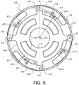
- the driven member 15 is rotated in one direction (e.g. the counterclockwise direction in FIG. 5 ) about the center of rotation RC as illustrated in FIG. 5
- the crank members 22 are rotated in the direction opposite to the driven member 15 (e.g. the clockwise direction in FIGS. 5 and 6A ) about the first coupling shaft A1 from the position in the equilibrium state (see the dash-and-dot line in FIG.
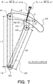
- a centrifugal force Fc acts on each of the crank members 22 (center of gravity G) as illustrated in FIG. 7 .
- the restoring force Fr which acts on each of the crank members 22 is transferred to the inertial mass body 24 via the second coupling shaft A2 and the connecting rod 23.
- ⁇ is the angle formed by the direction of the centrifugal force Fc which acts on the crank member 22 and the direction from the center of the first coupling shaft A1 toward the center of gravity G (the center of the second coupling shaft A2) of the crank member 22.
- m denotes the weight of the crank member 22
- ⁇ denotes the rotational angular velocity of the driven member 15 (the same applies to FIG. 9 ).
- the restoring force Fr which acts on each of the crank members 22 comes to overcome a force (moment of inertia) that acts to rotate the crank member 22 and the inertial mass body 24 in the rotational direction in which the crank member 22 and the inertial mass body 24 have been rotated so far, at a turn-back position (see the solid line in FIG. 6A ) at which the crank member 22 has been rotated in one direction (the clockwise direction in FIG. 6A ) about the first coupling shaft A1 from the position in the equilibrium state, that is, a turn-back position determined in accordance with the amplitude (vibration level) of vibration transferred from the engine EG to the driven member 15.
- a force misment of inertia
- each of the crank members 22 is rotated in the direction opposite to the direction in which the crank member 22 has been rotated so far about the first coupling shaft A1, and returned to the position in the equilibrium state illustrated in FIG. 6B from the turn-back position.
- the inertial mass body 24 is rotated in the direction opposite to the direction in which the inertial mass body 24 has been rotated so far about the center of rotation RC in conjunction with each of the crank members 22, and returned to the position in the equilibrium state (the center of the swing range) illustrated in FIG. 6B from one end of the swing range which is determined in accordance with the vibration angle (swing range) of the crank member 22.
- each of the crank members 22 is rotated in the same direction as the driven member 15 (e.g. the clockwise direction in FIGS. 6C and 8 ) about the first coupling shaft A1 from the position in the equilibrium state (see the dash-and-dot line in FIG. 6C ) because of the moment of inertia (difficulty of rotation) of the inertial mass body 24 as illustrated in FIGS. 6C and 8 .
- the vibration damping device 20 is configured to meet the relationship L1 + L2 > L3 + L4, the inertial mass body 24 is rotated in the direction opposite to the driven member 15 and the crank members 22 (e.g. the counterclockwise direction in FIGS. 6C and 8 ) about the center of rotation RC of the driven member 15 from the position in the equilibrium state (the center of the swing range) as illustrated in FIGS. 6C and 8 with motion of the crank members 22 transferred to the inertial mass body 24 via the connecting rods 23.
- the crank members 22 e.g. the counterclockwise direction in FIGS. 6C and 8
- the centrifugal force Fc acts on each of the crank members 22 (center of gravity G), and a component force of the centrifugal force Fc which acts on each of the crank members 22, that is, the restoring force Fr, is transferred to the inertial mass body 24 via the second coupling shaft A2 and the connecting rods 23.
- the restoring force Fr which acts on each of the crank members 22 comes to overcome a force (moment of inertia) that acts to rotate the crank member 22 and the inertial mass body 24 in the rotational direction in which the crank member 22 and the inertial mass body 24 have been rotated so far, at a turn-back position (see the solid line in FIG.
- each of the crank members 22 is rotated in the direction opposite to the direction in which the crank member 22 has been rotated so far about the first coupling shaft A1, and returned to the position in the equilibrium state illustrated in FIG. 6B from the turn-back position.
- the inertial mass body 24 is rotated in the direction opposite to the direction in which the inertial mass body 24 has been rotated so far about the center of rotation RC in conjunction with each of the crank members 22, and returned to the position in the equilibrium state (the center of the swing range) illustrated in FIG. 6B from the other end of the swing range which is determined in accordance with the vibration angle (swing range) of the crank member 22.
- each of the crank members 22, which serves as a restoring force generation member, of the vibration damping device 20 is swung (makes reciprocal rotational motion) about the first coupling shaft A1 between the position in the equilibrium state and the turn-back position which is determined in accordance with the amplitude (vibration level) of vibration transferred from the engine EG to the driven member 15, and the inertial mass body 24 is swung (makes reciprocal rotational motion) in the direction opposite to the driven member 15 about the center of rotation RC within the swing range which is determined in accordance with the vibration angle (swing range) of the crank member 22 and which is centered on the position in the equilibrium state.
- the inertial mass body 24 moves from the position in the equilibrium state to one end of the swing range, thereafter returns to the position in the equilibrium state, further moves to the other end of the swing range, and thereafter returns to the position in the equilibrium state. Consequently, vibration that is opposite in phase to vibration transferred from the engine EG to the drive member 11 is applied from the inertial mass body 24 which is swung to the driven member 15 via the connecting rods 23 and the crank members 22, so that it is possible to damp vibration of the driven member 15.
- a vibration damping device that does not meet the relationship L1 + L2 > L3 + L4 as with the damper device described in Patent Document 1
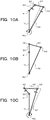
- the crank member 22 is always swung (makes reciprocal rotational motion) in the direction opposite to the driven member 15 about the first coupling shaft A1 within the swing range which is centered on the position in the equilibrium state, as with the inertial mass body 24, as illustrated in FIGS. 10A, 10B, and 10C .
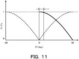
- a component force of the centrifugal force which acts on the crank member 22 in a direction that is orthogonal to the direction from the center of the first coupling shaft A1 toward the center of gravity G of the crank member 22 is zero in the equilibrium state illustrated in FIG. 10B . That is, in the vibration damping device according to the comparative example, the restoring force Fr which acts on the crank member 22 which is swung in the swing range which is centered on the position in the equilibrium state is zero (minimum) at the position in the equilibrium state (at a vibration angle ⁇ of 0° in FIG. 11 ) as indicated by the broken line in FIG. 11 , and the ratio (Fr/Fc) of the restoring force Fr to the centrifugal force Fc is increased as the vibration angle ⁇ becomes larger (as the crank member 22 approaches an end portion of the swing range).
- a component force of the centrifugal force which acts on the crank member 22 in a direction that is orthogonal to the direction from the center of the first coupling shaft A1 toward the center of gravity G of the crank member 22 in the equilibrium state illustrated in FIG. 6B is more than zero. That is, in the vibration damping device 20, the restoring force Fr which acts on the crank member 22 which is swung between the position in the equilibrium state and the turn-back position is maximum at the position in the equilibrium state (at a vibration angle ⁇ of 0° in FIG. 11 ), and reduced as the vibration angle ⁇ becomes larger, as indicated by the solid line in FIG. 11 .
- a restoring force does not act on each of the crank members 22 momentarily when the equilibrium state is established while the crank members 22 and the inertial mass body 24 are swung within their respective swing ranges in the vibration damping device according to the comparative example, whereas a restoring force that acts to return the mass body 24 to the position in the equilibrium state, that is, the center of the swing range, always acts on each of the crank members 22 while the crank members 22 and the inertial mass body 24 are swung within their respective swing ranges in the vibration damping device 20.
- the inertial mass body 24 moves from the position in the equilibrium state to one end of the swing range, thereafter returns to the position in the equilibrium state, further moves to the other end of the swing range, and thereafter returns to the position in the equilibrium state.
- the vibration angle ⁇ that is, the swing range, of the crank member 22 about the first coupling shaft A1 which matches vibration transferred to the driven member 15 is small compared to the inertial mass body 24.
- motion of the connecting rods 23 and the inertial mass body 24 is similar to motion of two links that constitute a toggle mechanism, which significantly restricts swing of the crank members 22 compared to the inertial mass body 24 as seen from FIGS. 6A, 6B, and 6C .
- the direction of the restoring force Fr is very close to the direction of the centrifugal force Fc (the angle ⁇ is closer to 90°).
- the fact that a larger restoring force Fr may be applied to the crank member 22 (and the inertial mass body 24) means that the vibration damping device 20 has high torsional rigidity.
- the crank member 22 is swung about the first coupling shaft A1 between the position in the equilibrium state and the turn-back position at which the crank member 22 has been rotated in one direction about the first coupling shaft A1 from the position in the equilibrium state. That is, in the vibration damping device 20, as illustrated in FIGS.
- the vibration damping device which meets the relationship L1 + L2 ⁇ L3 + L4 such as the damper device described in Patent Document 1, as illustrated in FIGS. 10A, 10B, and 10C , the crank member 22 is always rotated in the direction opposite to the driven member 15 about the first coupling shaft A1 as with the inertial mass body 24.
- the weight of the crank member 22 greatly affects both the equivalent rigidity K and the equivalent mass M, and thus it is not easy to improve the degree of freedom in setting of the vibration order q as with the vibration damping device 20 according to the present embodiment.
- ⁇ L3/(L3 + L4) of the interaxial distance L3 to the sum of the interaxial distances L3 and L4.
- the vibration angle of the crank member 22 about the first coupling shaft A1 can be further reduced by making the interaxial distance L3 shorter. Consequently, it is possible to further reduce the effect of the weight of the crank member 22 on the equivalent mass M, and to make the entire device compact by causing an end portion of the crank member 22 on the opposite from the first coupling shaft A1 to be moved toward the center of rotation RC (or reducing the amount of projection toward the radially outer side as much as possible).
- the interaxial distance L1 between the center of rotation RC and the first coupling shaft A1 is determined to be longer than the interaxial distances L2, L3, and L4. Consequently, the center of gravity G (second coupling shaft A2) of the crank member 22 can be positioned on the radially outer side with the crank member 22 spaced away from the center of rotation RC of the driven member 15.
- the center of gravity G (second coupling shaft A2) of the crank member 22 can be positioned on the radially outer side with the crank member 22 spaced away from the center of rotation RC of the driven member 15.
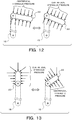
- the crank member 22 can be disposed along a circumference that passes through the center of the first coupling shaft A1 and that is centered on the center of rotation RC, and the vibration angle of the crank member 22 about the first coupling shaft A1 can be reduced. Consequently, as seen from FIG. 12 , it is possible to reduce the effect of a force due to a centrifugal hydraulic pressure that acts on the crank member 22 in the fluid transmission chamber 9 which is filled with working oil on the restoring force Fr, and to reduce fluctuations in force due to the centrifugal hydraulic pressure which is caused when the crank member 22 is swung, compared to the vibration damping device (see FIG.
- the vibration damping device 20 By configuring the vibration damping device 20 so as to meet L1 > L4 > L2 > L3, practically good equivalent rigidity K can be secured, and the effect of the weight of the crank member 22 on the equivalent mass M can be reduced to be practically ignorable. As a result, it is possible to damp vibration significantly well by easily causing the vibration order q of the vibration damping device 20 to coincide with (approximate) the order of vibration to be damped.
- the maximum vibration angle (swing limit) of each of the crank members 22 and the maximum swing range of the inertial mass body 24 are determined from the interaxial distances L1, L2, L3, and L4.
- the interaxial distances L1, L2, L3, and L4 of the vibration damping device 20 are preferably determined in consideration of the amplitude (vibration level) of vibration transferred to the driven member 15 so that the vibration damping device 20 do not fail to damp vibration transferred to the driven member 15.
- the vibration damping device 20 is configured so as to meet 60° ⁇ ⁇ ⁇ 120°, more preferably 70° ⁇ ⁇ ⁇ 90°, when the angle formed by the direction from the center of the first coupling shaft A1 toward the center of the second coupling shaft A2 and the direction from the center of the second coupling shaft A2 toward the center of rotation RC in the equilibrium state in which the center of the second coupling shaft A2, the center of the third coupling shaft A3, and the center of rotation RC of the driven member 15 are positioned on one line is defined as " ⁇ ".
- the inertial mass body 24 can be prevented from being swung greatly to one side of the swing range to reach the swing limit (dead center) on the one side and being swung slightly to the other side when the rotational speed of the driven member 15 is low.
- the vibration damping device 20 By rotatably supporting (aligning) the inertial mass body 24 which is annular using the driven member 15 as in the present embodiment, further, it is possible to make the vibration damping device 20 compact, and to smoothly swing the inertial mass body 24 about the center of rotation RC of the driven member 15 (rotary element) when the crank members 22 are swung.
- the effect of the centrifugal force and the centrifugal liquid pressure which act on the inertial mass body 24 on swing of the inertial mass body 24 can be eliminated by forming the inertial mass body 24 to be annular.
- the inertial mass body 24 which is annular on the radially outer side of the driven member 15, additionally, it is possible to increase the moment of inertia of the inertial mass body 24 while suppressing an increase in weight of the inertial mass body 24, and to suppress an increase in axial length of the vibration damping device 20.
- FIG. 14 illustrates the results of analyzing the relationship between a vibration angle ⁇ of the inertial mass body 24 about the center of rotation RC and an effective order qeff for the plurality of models of the vibration damping device 20 (ratio p).
- ratio p an order deviation occurred when the vibration angle ⁇ of the inertial mass body 24 about the center of rotation RC was significantly small, and the amount of deviation of the effective order qeff from the target order qtag went out of the permissible range before the vibration angle ⁇ reached the maximum vibration angle.
- the effective order qeff generally coincided with the target order qtag over the entire range of the vibration angle ⁇ .
- the vibration damping performance of the vibration damping device 20 may be improved better by reducing variations in the effective order qeff (order deviation) at the time when the vibration angle ⁇ of the inertial mass body 24 about the center of rotation RC is large.
- the vibration damping device 20 may be configured so as to meet the relationship Lg > L2 as illustrated in FIG. 15 .
- the center of gravity G of the crank member 22 is positioned on a line that passes through the centers of the first and second coupling shafts A1 and A2. However, it is not necessary that the center of gravity G should be positioned on the line which passes through the centers of the first and second coupling shafts A1 and A2.
- the inertial mass body 24 which is annular may be replaced with a plurality of (e.g. four) mass bodies that have the same specifications (such as dimensions and weight) as each other.
- the mass bodies may be constituted from metal plates that have an arcuate planar shape, for example, and that are coupled to the driven member 15 via the crank member 22 (two plate members 220) and two connecting rods 23 so as to be arranged at intervals (equal intervals) in the circumferential direction in the equilibrium state and swing about the center of rotation RC.
- a guide portion that guides each of the mass bodies so as to swing about the center of rotation RC while receiving a centrifugal force (centrifugal hydraulic pressure) that acts on the mass body may be provided at the outer peripheral portion of the driven member 15. Also with the vibration damping device 20 which includes such a plurality of mass bodies, it is possible to improve the degree of freedom in setting of the vibration order q, which allows improving the vibration damping performance while suppressing an increase in weight or size of the crank member 22 and hence the entire device.
- the vibration damping device 20 may be coupled to the drive member (input element) 11 of the damper device 10.
- the vibration damping device 20 may include a dedicated support member (first link) that constitutes a turning pair with the crank member 22 by swingably supporting the crank member 22 and that constitutes a turning pair with the inertial mass body 24. That is, the crank member 22 may be coupled to a rotary element indirectly via a dedicated support member that serves as the first link.
- the support member of the vibration damping device 20 should be coupled so as to rotate coaxially and together with a rotary element, such as the drive member 11 or the driven member 15 of the damper device 10, for example, vibration of which is to be damped. Also with the thus configured vibration damping device 20, it is possible to damp vibration of a rotary element well.
- the vibration damping device 20 may be applied to a damper device 10B illustrated in FIG. 16 .
- the damper device 10B of FIG. 16 includes the drive member (input element) 11, an intermediate member 12 (intermediate element), and the driven member 15 (output element) as rotary elements, and also includes a first spring SP1 disposed between the drive member 11 and the intermediate member 12 and a second spring SP2 disposed between the intermediate member 12 and the driven member 15 as torque transfer elements.
- the vibration damping device 20 may be coupled to the intermediate member 12 of the damper device 10B as illustrated in the drawing, or may be coupled to the drive member 11 or the driven member 15.
- the vibration damping device 20 may be applied to a damper device 10C illustrated in FIG. 17 .
- the damper device 10C of FIG. 17 includes the drive member (input element) 11, a first intermediate member (first intermediate element) 121, a second intermediate member (second intermediate element) 122, and the driven member (output element) 15 as rotary elements, and also includes a first spring SP1 disposed between the drive member 11 and the first intermediate member 121, a second spring SP2 disposed between the first intermediate member 121 and the second intermediate member 122, and a third spring SP3 disposed between the second intermediate member 122 and the driven member 15 as torque transfer elements.
- the vibration damping device 20 may be coupled to the first intermediate member 121 of the damper device 10C as illustrated in the drawing, or may be coupled to the drive member 11, the second intermediate member 122, or the driven member 15. In any case, by coupling the vibration damping device 20 to a rotary element of the damper device 10, 10B, or 10C, it is possible to damp vibration significantly well using both the damper device 10 to 10C and the vibration damping device 20 while suppressing an increase in weight of the damper device 10 to 10C.
- the present disclosure provides a vibration damping device (20) that includes: a support member (15) that rotates together with a rotary element (15), to which torque from an engine is transferred, about a center of rotation (RC) of the rotary element (15); a restoring force generation member (22) that is coupled to the support member (15) via a coupling shaft (A1) and that is swingable about the coupling shaft (A1) along with rotation of the support member (15); and an inertial mass body (24) coupled to the support member (15) via the restoring force generation member (22) and swung about the center of rotation (RC) in conjunction with the restoring force generation member (22) along with rotation of the support member (15), the vibration damping device (20) damping vibration of the rotary element (15), in which when the support member (15) is rotated, a component force of a centrifugal force that acts on the restoring force generation member (22) along with rotation of the support member (15) in a direction that is orthogonal to a direction from a center of the coupling shaft (
- a component force of a centrifugal force that acts on the restoring force generation member along with rotation of the support member in a direction that is orthogonal to the direction from the center of the coupling shaft toward the center of gravity of the restoring force generation member acts as a restoring force (moment) that acts to return the inertial mass body to the center of the swing range.
- the component force is maximum when the inertial mass body is positioned at the center of the swing range.
- the restoring force for the same centrifugal force which acts on the restoring force generation member can be increased over the entire swing range of the restoring force generation member compared to a case where the component force of the centrifugal force which acts on the restoring force generation member in a direction that is orthogonal to the direction from the center of the coupling shaft toward the center of gravity of the restoring force generation member is zero when the inertial mass body is positioned at the center of the swing range.
- the vibration damping device it is possible to increase the equivalent rigidity of the vibration damping device while suppressing an increase in weight of the restoring force generation member, which can improve the degree of freedom in setting of the equivalent rigidity and the equivalent mass, that is, the vibration order. As a result, it is possible to further improve the vibration damping performance while suppressing an increase in weight or size of the restoring force generation member and hence the entire device.
- the restoring force generation member (22) may be swung about the coupling shaft (A1) between a position in an equilibrium state, in which the inertial mass body (24) is positioned at the center of the swing range, and a turn-back position, at which the inertial mass body (24) has been rotated in one direction about the coupling shaft (A1) from the position in the equilibrium state. That is, in such a vibration damping device, the inertial mass body is always rotated in the direction opposite to (in the phase opposite to) the rotary element (support member) about the center of rotation, whereas the restoring force generation member is not only rotated in the direction opposite to (in the phase opposite to) the rotary element etc. about the coupling shaft, but also rotated in the same direction as (in the same phase as) the rotary element etc. Consequently, it is possible to reduce the effect of the weight of the restoring force generation member on the equivalent mass of the vibration damping device.
- the inertial mass body (24) may move from the position in the equilibrium state to one end of the swing range, thereafter return to the position in the equilibrium state, further move to the other end of the swing range, and thereafter return to the position in the equilibrium state. Consequently, it is possible to reduce the vibration angle (swing range) of the restoring force generation member about the coupling shaft, and to increase the restoring force which acts on the restoring force generation member (and the inertial mass body) which is swung.
- the vibration damping device (20) may further include a connecting member (23) rotatably coupled to the restoring force generation member (22) via a second coupling shaft (A2) and rotatably coupled to the inertial mass body (24) via a third coupling shaft (A3); and when an interaxial distance between the center of rotation (RC) of the rotary element (15) and the coupling shaft (A1) is defined as "L1", an interaxial distance between the coupling shaft (A1) and the second coupling shaft (A2) is defined as "L2", an interaxial distance between the second coupling shaft (A2) and the third coupling shaft (A3) is defined as "L3", and an interaxial distance between the third coupling shaft (A3) and the center of rotation (RC) is defined as "L4", L1 + L2 > L3 + L4 may be met.
- the support member, the restoring force generation member, the connecting member, and the inertial mass body constitute a four-node rotary link mechanism in which the support member (rotary element) serves as a fixed node, and a restoring force (moment) that acts to return the inertial mass body to the center of the swing range (position in the equilibrium state) acts on the restoring force generation member which is swung with respect to the support member.
- the vibration damping device By configuring the vibration damping device so as to meet the relationship L1 + L2 > L3 + L4, the angle which is formed by the direction of the centrifugal force which acts on the restoring force generation member and the direction from the center of the coupling shaft, which couples the support member and the restoring force generation member to each other, toward the center of gravity of the restoring force generation member can be approximated to 90°. That is, with the vibration damping device, it is possible to approximate the direction of the restoring force which acts on the restoring force generation member (a component force of the centrifugal force) to the direction of the centrifugal force.
- the restoring force for the same centrifugal force which acts on the restoring force generation member can be increased compared to a case where the relationship L1 + L2 > L3 + L4 is not met, which makes it possible to increase the equivalent rigidity of the vibration damping device while suppressing an increase in weight of the restoring force generation member.
- the effect of the weight of the restoring force generation member on the equivalent mass of the vibration damping device can be made very small, which can improve the degree of freedom in setting of the equivalent rigidity and the equivalent mass, that is, the vibration order.
- the vibration damping device may be configured such that a component force of a centrifugal force that acts on the restoring force generation member along with rotation of the support member in a direction that is orthogonal to the direction from the center of the coupling shaft toward the center of the second coupling shaft is larger than zero in the equilibrium state in which the inertial mass body is positioned at the center of the swing range.
- the interaxial distance L3 may be shorter than the interaxial distances L1, L2, and L4. That is, the equivalent rigidity of the vibration damping device discussed above is inversely proportional to the square value of the ratio (L3/(L3 + L4)) of the interaxial distance L3 to the sum of the interaxial distances L3 and L4.
- the vibration angle of the restoring force generation member can be further reduced by making the interaxial distance L3 shorter, which makes it possible to further reduce the effect of the weight of the restoring force generation member on the equivalent mass, and to make the entire device compact.
- the interaxial distance L1 may be longer than the interaxial distances L2, L3, and L4. Consequently, the center of gravity of the restoring force generation member can be positioned on the radially outer side with the restoring force generation member spaced away from the center of rotation of the rotary element, which makes it possible to increase the component force of the centrifugal force which acts on the restoring force generation member, that is, the restoring force. Additionally, by making the interaxial distance L1 the longest while meeting the relationship L1 + L2 > L3 + L4, the restoring force generation member can be disposed along a circumference that passes through the center of the coupling shaft and that is centered on the center of rotation of the rotary element, and the vibration angle of the restoring force generation member can be reduced.
- the vibration damping device is disposed in oil, it is possible to reduce the effect of a force due to a centrifugal hydraulic pressure that acts on the restoring force generation member on the restoring force, and to reduce fluctuations in force due to the centrifugal hydraulic pressure which is caused when the restoring force generation member is swung.
- the vibration damping device (20) may be configured such that L1 > L4 > L2 > L3 is met. Consequently, it is possible to secure practically good equivalent rigidity of the vibration damping device, and to reduce the effect of the weight of the restoring force generation member on the equivalent mass of the vibration damping device to be practically ignorable.
- the vibration damping device (20) may be configured such that, when an angle is defined as " ⁇ ", 60° ⁇ ⁇ ⁇ 120° is met, the angle being formed by a direction from the center of the first coupling shaft (A1) toward a center of the second coupling shaft (A2) and a direction from the center of the second coupling shaft (A2) toward the center of rotation (RC) with the center of the second coupling shaft (A2), a center of the third coupling shaft (A3), and the center of rotation (RC) positioned on one line.
- the inertial mass body can be prevented from being swung greatly to one side of the swing range to reach the swing limit (dead center) on the one side and being swung slightly to the other side when the rotational speed of the rotary element is low.
- it is possible to improve the vibration damping performance by causing the inertial mass body to be swung symmetrically with respect to the center of the swing range (position in the equilibrium state) since the time when the rotational speed of the rotary element is relatively low.
- the vibration damping device (20) may be configured such that, when a distance from the center of the first coupling shaft (A1) to the center of gravity (G) of the restoring force generation member (22) is defined as "Lg", Lg ⁇ L2 is met. Consequently, it is possible to further increase the restoring force which acts on the restoring force generation member using leverage.
- the restoring force generation member (22) may include at least one plate member (220) that has an arcuate planar shape. Consequently, in the case where the vibration damping device is disposed in oil, it is possible to reduce the effect of a force due to a centrifugal hydraulic pressure that acts on the restoring force generation member on the restoring force well.
- the inertial mass body (24) may be an annular member disposed so as to surround the support member (15), and be rotatably supported by the support member (15).
- the inertial mass body is rotatably supported by the support member in this way, it is possible to make the vibration damping device compact, and to smoothly swing the inertial mass body about the center of rotation of the rotary element (support member) when the restoring force generation member is swung.
- the effect of the centrifugal force (and the centrifugal liquid pressure) which acts on the inertial mass body on swing of the inertial mass body can be eliminated by forming the inertial mass body to be annular.
- the inertial mass body which is annular on the radially outer side of the support member additionally, it is possible to increase the moment of inertia of the inertial mass body while suppressing an increase in weight of the inertial mass body, and to suppress an increase in axial length of the vibration damping device.
- the support member (15) may rotate coaxially and integrally with a rotary element of a damper device (10, 10B, 10C) that has a plurality of rotary elements (11, 12, 121, 122, 15) that include at least an input element (11) and an output element (15) and an elastic body (SP, SP1, SP2, SP3) that transfers torque between the input element (11) and the output element (15).
- the input element (11) of the damper device (10, 10B, 10C) may be functionally (directly or indirectly) coupled to an output shaft of a motor (EG).
- the output element (15) of the damper device (10, 10B, 10C) may be functionally (directly or indirectly) coupled to an input shaft (Is) of a transmission (TM).
- the invention according to the present disclosure can be utilized in the field of manufacture of vibration damping devices that damp vibration of a rotary element.
Landscapes
- Engineering & Computer Science (AREA)
- General Engineering & Computer Science (AREA)
- Mechanical Engineering (AREA)
- Physics & Mathematics (AREA)
- Acoustics & Sound (AREA)
- Aviation & Aerospace Engineering (AREA)
- Vibration Prevention Devices (AREA)
Abstract
Description
- The invention according to the present disclosure relates to a vibration damping device that damps vibration of a rotary element.
- There has hitherto been known a damper that includes: a link mechanism that includes a first link serving as a crank member coupled to a crankshaft and a second link serving as a connecting rod coupled to the first link; and an annular inertial body coupled to the second link and coupled so as to be turnable by a predetermined angle relative to the crankshaft via the link mechanism (see
Patent Document 1, for example). In the damper, the point of coupling between the crankshaft and the first link is spaced away in the circumferential direction from the point of coupling between the inertial body and the second link, and a mass body is formed on the first link. The first link and the second link of the link mechanism operate to keep a state in which the first link and the second link are balanced with respective centrifugal forces that act thereon when the crankshaft is rotated. Therefore, a force (a force in the rotational direction) that acts to keep the link mechanism in an equilibrium state (balanced state) acts on the inertial body, and such a force causes the inertial body to make motion that is generally similar to that made when the inertial body is coupled to a rotary shaft via a spring member. Consequently, with the link mechanism functioning as a spring member and with the inertial body functioning as a mass body, twisting vibration caused in the crankshaft is reduced. - [Patent Document 1] Japanese Patent Application Publication No.
2001-263424 JP 2001-263424 A - In order for the damper according to the related art to damp targeted vibration well, it is necessary to approximate a vibration order q of the damper, which is represented as q = √(K/M) when the equivalent rigidity and the equivalent mass of the damper are defined as "K" and "M", respectively, to the order of the targeted vibration as much as possible. The equivalent rigidity K of the damper depends on a restoring force that acts to return the first and second links to their positions in the equilibrium state, that is, a component force of a centrifugal force that acts mainly on the first link. In the damper described in
Patent Document 1, however, the component force of the centrifugal force is zero at the center of the swing range (see the broken line inFIG. 11 ), and it is difficult to secure a sufficient restoring force over the entire swing range. If it is attempted to increase the weight of the first link (crank member) or the inertial body in order to increase the restoring force in the damper, an increase in weight or the size of the entire damper may be incurred. In the case where the weight of the first link cannot be increased because of constraints of the weight or the size in the damper, the targeted vibration may not be damped. - Thus, it is a main object of the invention according to the present disclosure to provide a vibration damping device which can improve the vibration damping performance while suppressing an increase in weight or size of the entire device.
- The present disclosure provides a vibration damping device that includes: a support member that rotates together with a rotary element, to which torque from an engine is transferred, about a center of rotation of the rotary element; a restoring force generation member that is coupled to the support member via a coupling shaft and that is swingable about the coupling shaft along with rotation of the support member; and an inertial mass body coupled to the support member via the restoring force generation member and swung about the center of rotation in conjunction with the restoring force generation member along with rotation of the support member, the vibration damping device damping vibration of the rotary element, in which when the support member is rotated, a component force of a centrifugal force that acts on the restoring force generation member along with rotation of the support member in a direction that is orthogonal to a direction from a center of the coupling shaft toward a center of gravity of the restoring force generation member always acts on the restoring force generation member as a restoring force that acts to return the inertial mass body to a center of a swing range, and the component force is maximum when the inertial mass body is positioned at the center of the swing range.
- In the vibration damping device, a component force of a centrifugal force that acts on the restoring force generation member along with rotation of the support member in a direction that is orthogonal to the direction from the center of the coupling shaft toward the center of gravity of the restoring force generation member acts as a restoring force (moment) that acts to return the inertial mass body to the center of the swing range. The component force is maximum when the inertial mass body is positioned at the center of the swing range. Consequently, the restoring force for the same centrifugal force which acts on the restoring force generation member can be increased over the entire swing range of the restoring force generation member compared to a case where the component force of the centrifugal force which acts on the restoring force generation member in a direction that is orthogonal to the direction from the center of the coupling shaft toward the center of gravity of the restoring force generation member is zero when the inertial mass body is positioned at the center of the swing range. Thus, with the vibration damping device, it is possible to increase the equivalent rigidity of the vibration damping device while suppressing an increase in weight of the restoring force generation member, which can improve the degree of freedom in setting of the equivalent rigidity and the equivalent mass, that is, the vibration order. As a result, it is possible to further improve the vibration damping performance while suppressing an increase in weight or size of the restoring force generation member and hence the entire device.
-
- [
FIG. 1] FIG. 1 is a schematic diagram illustrating a starting device that includes a vibration damping device according to the present disclosure. - [
FIG. 2] FIG. 2 is a front view of the vibration damping device according to the present disclosure. - [
FIG. 3] FIG. 3 is an enlarged sectional view illustrating an essential portion of the vibration damping device according to the present disclosure. - [
FIG. 4] FIG. 4 is an enlarged sectional view illustrating an essential portion of the vibration damping device according to the present disclosure. - [
FIG. 5] FIG. 5 is a front view illustrating operation of the vibration damping device according to the present disclosure. - [
FIG. 6A] FIG. 6A is a schematic diagram illustrating operation of the vibration damping device according to the present disclosure. - [
FIG. 6B] FIG. 6B is a schematic diagram illustrating operation of the vibration damping device according to the present disclosure. - [
FIG. 6C] FIG. 6C is a schematic diagram illustrating operation of the vibration damping device according to the present disclosure. - [
FIG. 7] FIG. 7 is a schematic diagram illustrating operation of the vibration damping device according to the present disclosure. - [
FIG. 8] FIG. 8 is a front view illustrating operation of the vibration damping device according to the present disclosure. - [
FIG. 9] FIG. 9 is a schematic diagram illustrating operation of a vibration damping device according to a comparative example. - [
FIG. 10A] FIG. 10A is a schematic diagram illustrating operation of the vibration damping device according to the comparative example. - [
FIG. 10B] FIG. 10B is a schematic diagram illustrating operation of the vibration damping device according to the comparative example. - [
FIG. 10C] FIG. 10C is a schematic diagram illustrating operation of the vibration damping device according to the comparative example. - [
FIG. 11] FIG. 11 is a chart illustrating the relationship between the vibration angle of a restoring force generation member included in the vibration damping device according to the present disclosure and the ratio of a restoring force to a centrifugal force that acts on the restoring force generation member. - [
FIG. 12] FIG. 12 is a schematic diagram illustrating operation of the vibration damping device according to the present disclosure. - [
FIG. 13] FIG. 13 is a schematic diagram illustrating operation of the vibration damping device according to the comparative example. - [
FIG. 14] FIG. 14 is a chart illustrating the results of analyzing the relationship between the vibration angle of a mass body about the center of rotation and the order of vibration damped by the vibration damping device according to the present disclosure. - [
FIG. 15] FIG. 15 is a schematic diagram illustrating a vibration damping device according to a modification of the present disclosure. - [
FIG. 16] FIG. 16 is a schematic diagram illustrating a modification of a damper device that includes the vibration damping device according to the present disclosure. - [
FIG. 17] FIG. 17 is a schematic diagram illustrating another modification of the damper device which includes the vibration damping device according to the present disclosure. - Now, an embodiment of the invention according to the present disclosure will be described with reference to the drawings.
-
FIG. 1 is a schematic diagram illustrating astarting device 1 that includes avibration damping device 20 according to the present disclosure. Thestarting device 1 illustrated in the drawing is mounted on a vehicle that includes an engine (internal combustion engine) EG that serves as a drive device (motor), for example. In addition to the vibration damping device (four-node link vibration absorption device) 20, thestarting device 1 includes: afront cover 3 that serves as an input member coupled to a crankshaft of the engine EG; a pump impeller (input-side fluid transmission element) 4 fixed to thefront cover 3 to rotate together with thefront cover 3; a turbine runner (output-side fluid transmission element) 5 that is rotatable coaxially with thepump impeller 4; adamper hub 7 that serves as an output member fixed to an input shaft IS of a transmission (power transfer device) TM that is an automatic transmission (AT), a continuously variable transmission (CVT), a dual clutch transmission (DCT), a hybrid transmission, or a speed reducer; a lock-up clutch 8 that is a hydraulic single-plate clutch, for example; adamper device 10; and so forth. - In the following description, unless specifically stated, the term "axial direction" basically indicates the direction of extension of the center axis (axis) of the
starting device 1 or the damper device 10 (vibration damping device 20). In addition, unless specifically stated, the term "radial direction" basically indicates the radial direction of thestarting device 1, thedamper device 10, or a rotary element of thedamper device 10 etc., that is, the direction of extension of a line that extends in directions (radial directions) that are orthogonal to the center axis of thestarting device 1 or thedamper device 10 from the center axis. Furthermore, unless specifically stated, the term "circumferential direction" basically indicates the circumferential direction of thestarting device 1, thedamper device 10, or a rotary element of thedamper device 10 etc., that is, a direction along the rotational direction of such a rotary element. - The
pump impeller 4 has a pump shell (not illustrated) tightly fixed to thefront cover 3, and a plurality of pump blades (not illustrated) disposed on the inner surface of the pump shell. Theturbine runner 5 has a turbine shell (not illustrated), and a plurality of turbine blades (not illustrated) disposed on the inner surface of the turbine shell. The inner peripheral portion of the turbine shell is fixed to thedamper hub 7 via a plurality of rivets. - The
pump impeller 4 and theturbine runner 5 face each other. Astator 6 is disposed between and coaxially with thepump impeller 4 and theturbine runner 5. Thestator 6 adjusts a flow of working oil (working fluid) from theturbine runner 5 to thepump impeller 4. Thestator 6 has a plurality of stator blades (not illustrated). The rotational direction of thestator 6 is set to only one direction by a one-way clutch 61. Thepump impeller 4, theturbine runner 5, and thestator 6 form a torus (annular flow passage) that allows circulation of working oil, and function as a torque converter (fluid transmission apparatus) with a torque amplification function. It should be noted, however, that thestator 6 and the one-way clutch 61 may be omitted from the startingdevice 1, and that thepump impeller 4 and theturbine runner 5 may function as a fluid coupling. - The lock-up
clutch 8 can establish and release lock-up in which thefront cover 3 and thedamper hub 7 are coupled to each other via thedamper device 10. In the present embodiment, the lock-upclutch 8 is constituted as a hydraulic single-plate clutch, and has a lock-up piston 80 (not illustrated) disposed inside thefront cover 3 and in the vicinity of the inner wall surface of thefront cover 3 on the engine EG side and fitted so as to be movable in the axial direction with respect to thedamper hub 7. A friction material is affixed to surfaces of the lock-uppiston 80 on the outer peripheral side and on thefront cover 3 side. A lock-up chamber (not illustrated) is defined between the lock-uppiston 80 and thefront cover 3. The lock-up chamber is connected to a hydraulic control device (not illustrated) via a working oil supply passage and an oil passage formed in the input shaft IS. - Working oil from the hydraulic control device, which is supplied radially outward from the side near the axis of the
pump impeller 4 and the turbine runner 5 (the vicinity of the one-way clutch 61) to thepump impeller 4 and the turbine runner 5 (torus) via the oil passage which is formed in the input shaft IS etc., can flow into the lock-up chamber of the lock-upclutch 8. Thus, if the pressure in afluid transmission chamber 9 defined by thefront cover 3 and the pump shell of thepump impeller 4 and the pressure in the lock-up chamber are kept equal to each other, the lock-uppiston 80 is not moved toward thefront cover 3, and the lock-uppiston 80 is not frictionally engaged with thefront cover 3. If the pressure in the lock-up chamber is decreased by the hydraulic control device (not illustrated), in contrast, the lock-uppiston 80 is moved toward thefront cover 3 by a pressure difference to be frictionally engaged with thefront cover 3. Consequently, the front cover 3 (engine EG) is coupled to thedamper hub 7 via thedamper device 10. A hydraulic multi-plate clutch that includes at least one friction engagement plate (a plurality of friction materials) may be adopted as the lock-upclutch 8. - As illustrated in
FIG. 1 , thedamper device 10 includes, as rotary elements, an annular drive member (input element) 11 coupled to the lock-uppiston 80 of the lock-upclutch 8 so as to rotate therewith, and an annular driven member (output element) 15 coupled to the input shaft IS of the transmission TM. Thedamper device 10 also includes a plurality of (e.g. four in the present embodiment) springs (elastic bodies) SP disposed at intervals in the circumferential direction on the same circumference. Arc coil springs, which are made of a metal material wound so as to have an axis that extends arcuately when no load is applied, or straight coil springs, which are made of a metal material spirally wound so as to have an axis that extends straight when no load is applied, are adopted as the springs SP. Alternatively, so-called double springs may be adopted as the springs SP. - The
drive member 11, which is an input element of thedamper device 10, includes: an annular first input plate member disposed in proximity to the lock-up piston 80 (front cover 3); and an annular second input plate member disposed close to thepump impeller 4 and theturbine runner 5 and away from the lock-uppiston 80 with respect to the first input plate member and coupled to the first input plate member via a plurality of rivets (neither of which is illustrated). - The first input plate member is rotatably supported by the
damper hub 7, and coupled to the lock-uppiston 80 so as to rotate therewith. In addition, the first input plate member has: a plurality of (e.g. four in the present embodiment) outer spring support portions that support (guide) the outer peripheral portions of the associated springs SP from the front cover 3 (engine EG) side; a plurality of (e.g. four in the present embodiment) inner spring support portions that support (guide) the inner peripheral portions of the associated springs SP from thefront cover 3 side; and a plurality of (e.g. four in the present embodiment) spring abutment portions (none of which is illustrated). The second input plate member has: a plurality of (e.g. four in the present embodiment) outer spring support portions that support (guide) the outer peripheral portions of the associated springs SP from the turbine runner 5 (transmission TM) side; a plurality of (e.g. four in the present embodiment) inner spring support portions that support (guide) the inner peripheral portions of the associated springs SP from theturbine runner 5 side; and a plurality of (e.g. four in the present embodiment) spring abutment portions (none of which is illustrated). - When the first and second input plate members are coupled to each other, the outer spring support portions of the first input plate member face the respective outer spring support portions of the second input plate member, and the inner spring support portions of the first input plate member face the respective inner spring support portions of the second input plate member. The springs SP are supported by the first and second input plate members which constitute the
drive member 11, and are arranged at intervals (equal intervals) in the circumferential direction in the vicinity of the inner peripheral portion of the turbine shell, for example. With thedamper device 10 in the attached state, in addition, the spring abutment portions of the first and second input plate members are provided between the springs SP which are adjacent to each other to abut against the end portions of such springs SP. - The driven
member 15 is disposed between the first input plate member and the second input plate member of thedrive member 11, and fixed to thedamper hub 7 together with the turbine shell of theturbine runner 5 via a plurality of rivets or by welding. Consequently, the drivenmember 15 is coupled to the input shaft IS of the transmission TM via thedamper hub 7. In addition, the drivenmember 15 has a plurality of (e.g. four in the present embodiment) spring abutment portions (not illustrated) that can abut against the end portions of the associated springs SP. With thedamper device 10 in the attached state, the spring abutment portions of the drivenmember 15 are provided between the springs SP which are adjacent to each other to abut against the end portions of such springs SP. Consequently, the drivenmember 15 is coupled to thedrive member 11 via the plurality of springs SP which act in parallel with each other. - The
vibration damping device 20 is coupled to the drivenmember 15 of thedamper device 10, and disposed inside thefluid transmission chamber 9 which is filled with working oil. As illustrated inFIGS. 2 to 4 , thevibration damping device 20 includes: the drivenmember 15 which serves as a support member (first link); a plurality of (e.g. four in the present embodiment) crankmembers 22 that serve as a restoring force generation member (second link); a plurality of (e.g. a total of eight in the present embodiment) connectingrods 23 that serve as a connecting member (third link); and a single annular inertial mass body (fourth link) 24. - The driven
member 15 has a plurality of (e.g. four in the present embodiment) projectingsupport portions 151 formed at intervals (equal intervals) in the circumferential direction to project radially outward from the outer periphery of the drivenmember 15. A first end portion of each crankmember 22 is rotatably coupled to a corresponding one of the projectingsupport portions 151 of the drivenmember 15. In the present embodiment, as illustrated inFIG. 3 , each of thecrank members 22 has twoplate members 220. Theplate members 220 are formed from a metal plate so as to have an arcuate planar shape, and the radius of curvature of the outer peripheral edges of theplate members 220 is determined to be the same as the radius of curvature of the outer peripheral edge of the inertialmass body 24. - The two
plate members 220 face each other in the axial direction of thedamper device 10 via the associated projectingsupport portion 151 and the inertialmass body 24, and are coupled to each other via a first coupling shaft A1. In the present embodiment, the first coupling shaft A1 is inserted through a coupling hole (circular hole) formed in the projectingsupport portion 151 of the drivenmember 15, and both end portions of the first coupling shaft A1 are supported by first end portions of the associatedplate members 220. Consequently, each of the crank members 22 (two plate members 220) is coupled (pinned) to the drivenmember 15 so as to be rotatable, that is, swingable, about the first coupling shaft A1. A bearing such as a ball bearing may be disposed in at least one of a space between theplate members 220 and the first coupling shaft A1 and a space between the projectingsupport portion 151 and the first coupling shaft A1. - Each of the connecting
rods 23 is formed from a metal plate to be narrow in width. As illustrated inFIG. 4 , two connectingrods 23 are provided for each of thecrank members 22. That is, one connectingrod 23 is interposed between one of theplate members 220 that constitute thecrank member 22 and the inertialmass body 24 in the axial direction, and one connectingrod 23 is interposed between theother plate member 220 that constitute thecrank member 22 and the inertialmass body 24 in the axial direction. A first end (end portion on the radially outer side) of each connectingrod 23 is rotatably coupled (pinned) to a corresponding one of theplate members 220 via a second coupling shaft A2. - In the present embodiment, the second coupling shaft A2 is disposed such that the center thereof extends coaxially with a line that passes through a center of gravity G of the crank member 22 (around the center portion of the
plate member 220 in the longitudinal direction). Consequently, the length from the center of the first coupling shaft A1, which couples the driven member 15 (projecting support portion 151) and thecrank member 22 to each other, to the center of gravity G of thecrank member 22 coincides with the length (interaxial distance) from the center of the first coupling shaft A1 to the center of the second coupling shaft A2, which couples thecrank member 22 and the connectingrod 23 to each other. In addition, the second end portion of the crank member 22 (plate members 220) is positioned on the opposite side of the second coupling shaft A2 from the first coupling shaft A1. A bearing such as a ball bearing may be disposed in at least one of a space between theplate members 220 and the second coupling shaft A2 and a space between the connectingrods 23 and the second coupling shaft A2. - The inertial
mass body 24 is an annular member formed from a metal plate. As illustrated inFIGS. 2 to 4 , the inertialmass body 24 has: a short cylindrical (annular)main body 240; and a plurality of (e.g. four in the present embodiment) projectingportions 241 provided at intervals (equal intervals) in the circumferential direction to project radially inward from the inner peripheral surface of themain body 240. The weight of the inertialmass body 24 is determined to be sufficiently larger than the weight of one crankmember 22, and to be sufficiently larger than the weight of one connectingrod 23. As illustrated inFIG. 2 , the projectingportions 241 of the inertialmass body 24 are disposed away from the projectingsupport portions 151 of the drivenmember 15 in the circumferential direction, and each held by two connectingrods 23 from both sides in the axial direction. In addition, each of the projectingportions 241 has a coupling hole (circular hole), and rotatably coupled (pinned) to second ends of (end portions on the radially inner side) of the two connectingrods 23 on both sides via a third coupling shaft A3 inserted through the coupling hole. Consequently, the inertialmass body 24 is coupled to the drivenmember 15 which serves as the support member via the plurality of connectingrods 23 and the plurality of crankmembers 22. A bearing such as a ball bearing may be disposed in at least one of a space between the connectingrods 23 and the third coupling shaft A3 and a space between the projectingportion 241 and the third coupling shaft A3. - In the present embodiment, further, the inner peripheral surface of the
main body 240 of the inertialmass body 24 is in sliding contact with the outer peripheral surfaces of the projectingsupport portions 151 of the drivenmember 15, and the inner peripheral surfaces of the projectingportions 241 of the inertialmass body 24 are in sliding contact with portions of an outerperipheral surface 152 of the drivenmember 15 between the projectingsupport portions 151 which are adjacent to each other. Consequently, the inertialmass body 24 which is annular is supported (aligned) by the drivenmember 15 such that the center of the inertialmass body 24 coincides with a center of rotation RC of the drivenmember 15 which is fixed to thedamper hub 7, and is rotatable about the center of rotation RC. It is possible to make thevibration damping device 20 compact by rotatably supporting the inertialmass body 24 using the driven member 15 (support member) in this way. In order to rotatably support the inertialmass body 24 using the drivenmember 15, it is only necessary that at least one of the inner peripheral surface of themain body 240 and the inner peripheral surfaces of the projectingportions 241 should be in sliding contact with the drivenmember 15. - In the
vibration damping device 20, the drivenmember 15, which serves as the first link (rotary element) which is rotated by power from the engine EG, and thecrank member 22, which is rotatably coupled to the drivenmember 15, constitute a turning pair. In addition, thecrank member 22 and the connectingrods 23, which are rotatably coupled to thecrank member 22, constitute a turning pair. Furthermore, the inertialmass body 24 is rotatably coupled to the connectingrods 23 to constitute a turning pair with the connectingrods 23, and rotatably supported by the drivenmember 15 to constitute a turning pair with the drivenmember 15. That is, the drivenmember 15, thecrank members 22, the connectingrods 23, and the inertialmass body 24 constitute a four-node rotary link mechanism in which the drivenmember 15 serves as a fixed node. - As illustrated in
FIG. 2 , in addition, when the length (the interaxial distance between the center of rotation RC and the first coupling shaft A1) from the center of rotation RC of the driven member 15 to the center of the first coupling shaft A1 which couples the driven member 15 and the crank member 22 (plate members 220) to each other is defined as "L1", the length (the interaxial distance between the first coupling shaft A1 and the second coupling shaft A2) from the center of the first coupling shaft A1 to the center of the second coupling shaft A2 which couples the crank member 22 (plate members 220) and the connecting rods 23 to each other is defined as "L2", the length (the interaxial distance between the second coupling shaft A2 and the third coupling shaft A3) from the center of the second coupling shaft A2 to the center of the third coupling shaft A3 which couples the connecting rods 23 and the inertial mass body 24 to each other is defined as "L3", and the length (the interaxial distance between the third coupling shaft A3 and the center of rotation RC) from the center of the third coupling shaft A3 to the center of rotation RC is defined as "L4", the driven member 15, the crank members 22, the connecting rods 23, and the inertial mass body 24 are configured to meet the relationship L1 + L2 > L3 + L4. - Furthermore, the connecting
rods 23 are configured such that the interaxial distance L3 between the second coupling shaft A2 and the third coupling shaft A3 is shorter than the interaxial distances L1, L2, and L4, and as short as possible in the range in which operation of thecrank members 22, the connectingrods 23, and the inertialmass body 24 is not hindered. In addition, the drivenmember 15 which serves as the first link is configured such that the interaxial distance L1 between the center of rotation RC and the first coupling shaft A1 is longer than the interaxial distances L2, L3, and L4. Consequently, in thevibration damping device 20 according to the present embodiment, the relationship L1 > L4 > L2 >L3 is met, and the drivenmember 15, thecrank members 22, the connectingrods 23, and the inertialmass body 24 constitute a double lever mechanism in which the drivenmember 15 which faces the connectingrods 23 as the shortest links serves as a fixed node. Additionally, in thevibration damping device 20 according to the present embodiment, when the length from the center of the first coupling shaft A1 which couples the drivenmember 15 and thecrank member 22 to each other to the center of gravity G of thecrank member 22 is defined as "Lg", the relationship Lg = L2 is met. - In addition, the "equilibrium state (balanced state)" of the
vibration damping device 20 corresponds to a state in which the resultant force of the total of centrifugal forces that act on the constituent elements of thevibration damping device 20 and forces that act on the nodes (the centers of the coupling shafts A1, A2, and A3 and the center of rotation RC) of thevibration damping device 20 is zero. When thevibration damping device 20 is in the equilibrium state, as illustrated inFIG. 2 , the center of the second coupling shaft A2 which couples thecrank member 22 and the connectingrods 23 to each other, the center of the third coupling shaft A3 which couples the connectingrods 23 and the inertialmass body 24 to each other, and the center of rotation RC of the drivenmember 15 are positioned on one line, and the inertialmass body 24 is positioned at the center of the swing range thereof. Furthermore, thevibration damping device 20 according to the present embodiment is configured so as to meet 60° ≤ α ≤ 120°, more preferably 70° ≤ α ≤ 90°, when the angle formed by the direction from the center of the first coupling shaft A1 toward the center of the second coupling shaft A2 and the direction from the center of the second coupling shaft A2 toward the center of rotation RC in the equilibrium state in which the center of the second coupling shaft A2, the center of the third coupling shaft A3, and the center of rotation RC are positioned on one line is defined as "α" (seeFIG. 2 ). - In the starting
device 1 which includes thedamper device 10 and thevibration damping device 20, when lock-up is released by the lock-upclutch 8, as seen fromFIG. 1 , torque (power) from the engine EG which serves as a motor is transferred to the input shaft IS of the transmission TM via a path that includes thefront cover 3, thepump impeller 4, theturbine runner 5, and thedamper hub 7. Meanwhile, when lock-up is established by the lock-upclutch 8, as seen fromFIG. 1 , torque (power) from the engine EG is transferred to the input shaft IS of the transmission TM via a path that includes thefront cover 3, the lock-up clutch 8 (lock-up piston 80), thedrive member 11, the springs SP, the drivenmember 15, and thedamper hub 7. - When the
drive member 11 which is coupled to thefront cover 3 by the lock-upclutch 8 is rotated along with rotation of the engine EG while lock-up is established by the lock-upclutch 8, the spring abutment portions of thedrive member 11 press first ends of the associated springs SP, and second ends of the springs SP press the associated spring abutment portions of the drivenmember 15. Consequently, torque from the engine EG transferred to thefront cover 3 is transferred to the input shaft IS of the transmission TM, and fluctuations in torque from the engine EG are damped (absorbed) mainly by the springs SP of thedamper device 10. - In the starting
device 1, further, when thedamper device 10, which is coupled to thefront cover 3 by the lock-upclutch 8 along with establishment of lock-up, is rotated together with thefront cover 3, the drivenmember 15 of thedamper device 10 is also rotated in the same direction as thefront cover 3 about the axis of the startingdevice 1. Along with rotation of the drivenmember 15, thecrank members 22, the connectingrods 23, and the inertialmass body 24 which constitute thevibration damping device 20 are swung with respect to the drivenmember 15, and accordingly vibration transferred from the engine EG to the drivenmember 15 is damped also by thevibration damping device 20. That is, thevibration damping device 20 is configured such that the order (vibration order q) of swing of thecrank members 22 and the inertialmass body 24 coincides with the order of vibration transferred from the engine EG to the driven member 15 (1.5 order in the case where the engine EG is e.g. a three-cylinder engine, and second order in the case where the engine EG is e.g. a four-cylinder engine), and damps vibration transferred from the engine EG to the drivenmember 15 irrespective of the rotational speed of the engine EG (driven member 15). Consequently, it is possible to damp vibration significantly well using both thedamper device 10 and thevibration damping device 20 while suppressing an increase in weight of thedamper device 10. - Next, operation of the
vibration damping device 20 will be described in detail. - As discussed above, the driven
member 15, thecrank members 22, the connectingrods 23, and the inertialmass body 24 which constitute thevibration damping device 20 constitute a four-node rotary link mechanism, that is, a double lever mechanism, that meets the relationship L1 + L2 > L3 + L4. Thus, when the drivenmember 15 is rotated in one direction (e.g. the counterclockwise direction inFIG. 5 ) about the center of rotation RC as illustrated inFIG. 5 , thecrank members 22 are rotated in the direction opposite to the driven member 15 (e.g. the clockwise direction inFIGS. 5 and6A ) about the first coupling shaft A1 from the position in the equilibrium state (see the dash-and-dot line inFIG. 6A ) because of the moment of inertia (difficulty of rotation) of the inertialmass body 24 as illustrated inFIGS. 5 and6A . When motion of each of thecrank members 22 is transferred to the inertialmass body 24 via the second coupling shaft A2 and the connectingrods 23, further, the inertialmass body 24 is rotated in the direction opposite to the driven member 15 (the same direction as thecrank members 22, i.e. the clockwise direction in the drawings) about the center of rotation RC from the position in the equilibrium state, that is, the center of the swing range. - When the driven
member 15 is rotated, in addition, a centrifugal force Fc acts on each of the crank members 22 (center of gravity G) as illustrated inFIG. 7 . A component force (= Fc·sinφ) of the centrifugal force Fc in a direction that is orthogonal to the direction from the center of the first coupling shaft A1 toward the center of gravity G of thecrank member 22 serves as a restoring force Fr that acts to return the crank member 22 (vibration damping device 20) to the position in the equilibrium state. The restoring force Fr which acts on each of thecrank members 22 is transferred to the inertialmass body 24 via the second coupling shaft A2 and the connectingrod 23. It should be noted, however, that "φ" is the angle formed by the direction of the centrifugal force Fc which acts on thecrank member 22 and the direction from the center of the first coupling shaft A1 toward the center of gravity G (the center of the second coupling shaft A2) of thecrank member 22. InFIG. 7 , in addition, "m" denotes the weight of thecrank member 22, and "ω" denotes the rotational angular velocity of the driven member 15 (the same applies toFIG. 9 ). - The restoring force Fr which acts on each of the
crank members 22 comes to overcome a force (moment of inertia) that acts to rotate thecrank member 22 and the inertialmass body 24 in the rotational direction in which thecrank member 22 and the inertialmass body 24 have been rotated so far, at a turn-back position (see the solid line inFIG. 6A ) at which thecrank member 22 has been rotated in one direction (the clockwise direction inFIG. 6A ) about the first coupling shaft A1 from the position in the equilibrium state, that is, a turn-back position determined in accordance with the amplitude (vibration level) of vibration transferred from the engine EG to the drivenmember 15. Consequently, each of thecrank members 22 is rotated in the direction opposite to the direction in which thecrank member 22 has been rotated so far about the first coupling shaft A1, and returned to the position in the equilibrium state illustrated inFIG. 6B from the turn-back position. In addition, the inertialmass body 24 is rotated in the direction opposite to the direction in which the inertialmass body 24 has been rotated so far about the center of rotation RC in conjunction with each of thecrank members 22, and returned to the position in the equilibrium state (the center of the swing range) illustrated inFIG. 6B from one end of the swing range which is determined in accordance with the vibration angle (swing range) of thecrank member 22. - Furthermore, when the driven
member 15 is rotated in the other direction (e.g. the clockwise direction inFIG. 8 ) about the center of rotation RC by vibration from the engine EG transferred via thedrive member 11 etc. as illustrated inFIG. 8 , each of thecrank members 22 is rotated in the same direction as the driven member 15 (e.g. the clockwise direction inFIGS. 6C and8 ) about the first coupling shaft A1 from the position in the equilibrium state (see the dash-and-dot line inFIG. 6C ) because of the moment of inertia (difficulty of rotation) of the inertialmass body 24 as illustrated inFIGS. 6C and8 . In this event, since thevibration damping device 20 is configured to meet the relationship L1 + L2 > L3 + L4, the inertialmass body 24 is rotated in the direction opposite to the drivenmember 15 and the crank members 22 (e.g. the counterclockwise direction inFIGS. 6C and8 ) about the center of rotation RC of the drivenmember 15 from the position in the equilibrium state (the center of the swing range) as illustrated inFIGS. 6C and8 with motion of thecrank members 22 transferred to the inertialmass body 24 via the connectingrods 23. - In this case as well, the centrifugal force Fc acts on each of the crank members 22 (center of gravity G), and a component force of the centrifugal force Fc which acts on each of the
crank members 22, that is, the restoring force Fr, is transferred to the inertialmass body 24 via the second coupling shaft A2 and the connectingrods 23. The restoring force Fr which acts on each of thecrank members 22 comes to overcome a force (moment of inertia) that acts to rotate thecrank member 22 and the inertialmass body 24 in the rotational direction in which thecrank member 22 and the inertialmass body 24 have been rotated so far, at a turn-back position (see the solid line inFIG. 6C ) at which thecrank member 22 has been rotated in one direction (the clockwise direction inFIG. 6C ) about the first coupling shaft A1 from the position in the equilibrium state, that is, a turn-back position determined in accordance with the amplitude (vibration level) of vibration transferred from the engine EG to the drivenmember 15. Consequently, each of thecrank members 22 is rotated in the direction opposite to the direction in which thecrank member 22 has been rotated so far about the first coupling shaft A1, and returned to the position in the equilibrium state illustrated inFIG. 6B from the turn-back position. In addition, the inertialmass body 24 is rotated in the direction opposite to the direction in which the inertialmass body 24 has been rotated so far about the center of rotation RC in conjunction with each of thecrank members 22, and returned to the position in the equilibrium state (the center of the swing range) illustrated inFIG. 6B from the other end of the swing range which is determined in accordance with the vibration angle (swing range) of thecrank member 22. - In this way, when the driven
member 15 is rotated in one direction, each of thecrank members 22, which serves as a restoring force generation member, of thevibration damping device 20 is swung (makes reciprocal rotational motion) about the first coupling shaft A1 between the position in the equilibrium state and the turn-back position which is determined in accordance with the amplitude (vibration level) of vibration transferred from the engine EG to the drivenmember 15, and the inertialmass body 24 is swung (makes reciprocal rotational motion) in the direction opposite to the drivenmember 15 about the center of rotation RC within the swing range which is determined in accordance with the vibration angle (swing range) of thecrank member 22 and which is centered on the position in the equilibrium state. That is, while each of thecrank members 22 makes motion of moving from the position in the equilibrium state to the turn-back position and returning from the turn-back position to the position in the equilibrium state twice, the inertialmass body 24 moves from the position in the equilibrium state to one end of the swing range, thereafter returns to the position in the equilibrium state, further moves to the other end of the swing range, and thereafter returns to the position in the equilibrium state. Consequently, vibration that is opposite in phase to vibration transferred from the engine EG to thedrive member 11 is applied from the inertialmass body 24 which is swung to the drivenmember 15 via the connectingrods 23 and thecrank members 22, so that it is possible to damp vibration of the drivenmember 15. - Here, in a vibration damping device that does not meet the relationship L1 + L2 > L3 + L4, that is, a vibration damping device (see
FIG. 9 ) according to a comparative example that meets the relationship L1 + L2 < L3 + L4 as with the damper device described inPatent Document 1, thecrank member 22 is always swung (makes reciprocal rotational motion) in the direction opposite to the drivenmember 15 about the first coupling shaft A1 within the swing range which is centered on the position in the equilibrium state, as with the inertialmass body 24, as illustrated inFIGS. 10A, 10B, and 10C . Furthermore, in the vibration damping device according to the comparative example, a component force of the centrifugal force which acts on thecrank member 22 in a direction that is orthogonal to the direction from the center of the first coupling shaft A1 toward the center of gravity G of thecrank member 22 is zero in the equilibrium state illustrated inFIG. 10B . That is, in the vibration damping device according to the comparative example, the restoring force Fr which acts on thecrank member 22 which is swung in the swing range which is centered on the position in the equilibrium state is zero (minimum) at the position in the equilibrium state (at a vibration angle θ of 0° inFIG. 11 ) as indicated by the broken line inFIG. 11 , and the ratio (Fr/Fc) of the restoring force Fr to the centrifugal force Fc is increased as the vibration angle θ becomes larger (as thecrank member 22 approaches an end portion of the swing range). - In the
vibration damping device 20 which meets the relationship L1 + L2 > L3 + L4, in contrast, a component force of the centrifugal force which acts on thecrank member 22 in a direction that is orthogonal to the direction from the center of the first coupling shaft A1 toward the center of gravity G of thecrank member 22 in the equilibrium state illustrated inFIG. 6B is more than zero. That is, in thevibration damping device 20, the restoring force Fr which acts on thecrank member 22 which is swung between the position in the equilibrium state and the turn-back position is maximum at the position in the equilibrium state (at a vibration angle θ of 0° inFIG. 11 ), and reduced as the vibration angle θ becomes larger, as indicated by the solid line inFIG. 11 . In other words, a restoring force does not act on each of thecrank members 22 momentarily when the equilibrium state is established while thecrank members 22 and the inertialmass body 24 are swung within their respective swing ranges in the vibration damping device according to the comparative example, whereas a restoring force that acts to return themass body 24 to the position in the equilibrium state, that is, the center of the swing range, always acts on each of thecrank members 22 while thecrank members 22 and the inertialmass body 24 are swung within their respective swing ranges in thevibration damping device 20. - In addition, in the
vibration damping device 20, as discussed above, while each of thecrank members 22 makes motion of moving from the position in the equilibrium state to the turn-back position and returning from the turn-back position to the position in the equilibrium state twice, the inertialmass body 24 moves from the position in the equilibrium state to one end of the swing range, thereafter returns to the position in the equilibrium state, further moves to the other end of the swing range, and thereafter returns to the position in the equilibrium state. Thus, the vibration angle θ, that is, the swing range, of thecrank member 22 about the first coupling shaft A1 which matches vibration transferred to the drivenmember 15 is small compared to the inertialmass body 24. That is, in thevibration damping device 20, motion of the connectingrods 23 and the inertialmass body 24 is similar to motion of two links that constitute a toggle mechanism, which significantly restricts swing of thecrank members 22 compared to the inertialmass body 24 as seen fromFIGS. 6A, 6B, and 6C . - As a result, in the
vibration damping device 20, as indicated inFIG. 11 , the swing range of thecrank member 22 is a narrow range to a position at which thecrank member 22 has been vibrated by a relatively small angle from the position in the equilibrium state (θ = 0°), and a component force of the centrifugal force Fc, that is, the restoring force Fr, is maximum in the equilibrium state in which the inertialmass body 24 is positioned at the center of the swing range. Thus, it is possible to increase the restoring force Fr (ratio Fr/Fc) for the same centrifugal force Fc which acts on thecrank member 22 over the entire swing range of thecrank member 22 compared to a case where a component force of the centrifugal force Fc which acts on thecrank member 22 in a direction that is orthogonal to the direction from the center of the first coupling shaft A1 toward the center of gravity G of thecrank member 22 is zero in the equilibrium state (the vibration damping device according to the comparative example). Specifically, in thevibration damping device 20, the direction of the restoring force Fr (= Fc·sinφ) which acts on the center of gravity G of thecrank member 22 can be made closer to the direction of the centrifugal force Fc by approximating the angle φ indicated inFIG. 7 to 90°. In a state that is close to the equilibrium state illustrated inFIG. 7 , in particular, the direction of the restoring force Fr is very close to the direction of the centrifugal force Fc (the angle φ is closer to 90°). The fact that a larger restoring force Fr may be applied to the crank member 22 (and the inertial mass body 24) means that thevibration damping device 20 has high torsional rigidity. Thus, with thevibration damping device 20, it is possible to increase an equivalent rigidity K while suppressing an increase in weight of thecrank member 22. - In addition, while the inertial
mass body 24 is swung about the center of rotation RC within the swing range which is centered on the position in the equilibrium state, thecrank member 22 is swung about the first coupling shaft A1 between the position in the equilibrium state and the turn-back position at which thecrank member 22 has been rotated in one direction about the first coupling shaft A1 from the position in the equilibrium state. That is, in thevibration damping device 20, as illustrated inFIGS. 6A, 6B, and 6C , while the inertialmass body 24 is always rotated in the direction opposite to (in the phase opposite to) the drivenmember 15 about the center of rotation RC, thecrank member 22 is not only rotated in the direction opposite to (in the phase opposite to) the drivenmember 15, but also rotated in the same direction as (in the same phase as) the drivenmember 15, about the first coupling shaft A1. Consequently, the effect of the weight of thecrank member 22 on an equivalent mass M of thevibration damping device 20 can be made very small. - Thus, with the
vibration damping device 20, it is possible to further improve the degree of freedom in setting of the equivalent rigidity K and the equivalent mass M, that is, the vibration order q = √(K/M), which allows improving the vibration damping performance significantly well while suppressing an increase in weight or size of thecrank member 22 and hence the entire device. In the vibration damping device which meets the relationship L1 + L2 < L3 + L4 such as the damper device described inPatent Document 1, as illustrated inFIGS. 10A, 10B, and 10C , thecrank member 22 is always rotated in the direction opposite to the drivenmember 15 about the first coupling shaft A1 as with the inertialmass body 24. Thus, with the damper device described inPatent Document 1, the weight of thecrank member 22 greatly affects both the equivalent rigidity K and the equivalent mass M, and thus it is not easy to improve the degree of freedom in setting of the vibration order q as with thevibration damping device 20 according to the present embodiment. - In addition, an analysis conducted by the inventors has revealed that the equivalent rigidity K of the
vibration damping device 20 is inversely proportional to the square value of a ratio ρ = L3/(L3 + L4) of the interaxial distance L3 to the sum of the interaxial distances L3 and L4. Thus, it is possible to increase the equivalent rigidity K while suppressing an increase in weight of thecrank member 22 by making the interaxial distance L3 between the second coupling shaft A2 and the third coupling shaft A3 shorter than the interaxial distance L1 between the center of rotation RC and the first coupling shaft A1, the interaxial distance L2 between the first coupling shaft A1 and the second coupling shaft A2, and the interaxial distance L4 between the third coupling shaft A3 and the center of rotation RC as discussed above. Additionally, the vibration angle of thecrank member 22 about the first coupling shaft A1 can be further reduced by making the interaxial distance L3 shorter. Consequently, it is possible to further reduce the effect of the weight of thecrank member 22 on the equivalent mass M, and to make the entire device compact by causing an end portion of thecrank member 22 on the opposite from the first coupling shaft A1 to be moved toward the center of rotation RC (or reducing the amount of projection toward the radially outer side as much as possible). - In the
vibration damping device 20, further, the interaxial distance L1 between the center of rotation RC and the first coupling shaft A1 is determined to be longer than the interaxial distances L2, L3, and L4. Consequently, the center of gravity G (second coupling shaft A2) of thecrank member 22 can be positioned on the radially outer side with thecrank member 22 spaced away from the center of rotation RC of the drivenmember 15. Thus, it is possible to secure a sufficient space for arrangement of the springs SP of thedamper device 10, and to increase a component force of the centrifugal force Fc that acts on thecrank member 22, that is, the restoring force Fr, without increasing the weight of thecrank member 22. - In addition, by making the interaxial distance L1 the longest while meeting the relationship L1 + L2 > L3 + L4, the
crank member 22 can be disposed along a circumference that passes through the center of the first coupling shaft A1 and that is centered on the center of rotation RC, and the vibration angle of thecrank member 22 about the first coupling shaft A1 can be reduced. Consequently, as seen fromFIG. 12 , it is possible to reduce the effect of a force due to a centrifugal hydraulic pressure that acts on thecrank member 22 in thefluid transmission chamber 9 which is filled with working oil on the restoring force Fr, and to reduce fluctuations in force due to the centrifugal hydraulic pressure which is caused when thecrank member 22 is swung, compared to the vibration damping device (seeFIG. 13 ) which meets the relationship L1 + L2 < L3 + L4 such as the damper device described inPatent Document 1. Additionally, it is possible to reduce the effect of the force due to the centrifugal hydraulic pressure which acts on thecrank member 22 on the restoring force Fr well by constituting thecrank member 22 using twoplate members 220 which have an arcuate planar shape as in the present embodiment. - By configuring the
vibration damping device 20 so as to meet L1 > L4 > L2 > L3, practically good equivalent rigidity K can be secured, and the effect of the weight of thecrank member 22 on the equivalent mass M can be reduced to be practically ignorable. As a result, it is possible to damp vibration significantly well by easily causing the vibration order q of thevibration damping device 20 to coincide with (approximate) the order of vibration to be damped. The maximum vibration angle (swing limit) of each of thecrank members 22 and the maximum swing range of the inertialmass body 24 are determined from the interaxial distances L1, L2, L3, and L4. Thus, the interaxial distances L1, L2, L3, and L4 of thevibration damping device 20 are preferably determined in consideration of the amplitude (vibration level) of vibration transferred to the drivenmember 15 so that thevibration damping device 20 do not fail to damp vibration transferred to the drivenmember 15. - In addition, the
vibration damping device 20 is configured so as to meet 60° ≤ α ≤ 120°, more preferably 70° ≤ α ≤ 90°, when the angle formed by the direction from the center of the first coupling shaft A1 toward the center of the second coupling shaft A2 and the direction from the center of the second coupling shaft A2 toward the center of rotation RC in the equilibrium state in which the center of the second coupling shaft A2, the center of the third coupling shaft A3, and the center of rotation RC of the drivenmember 15 are positioned on one line is defined as "α". Consequently, the inertialmass body 24 can be prevented from being swung greatly to one side of the swing range to reach the swing limit (dead center) on the one side and being swung slightly to the other side when the rotational speed of the drivenmember 15 is low. As a result, it is possible to improve the vibration damping performance of thevibration damping device 20 by causing the inertialmass body 24 to be swung symmetrically with respect to the position in the equilibrium state (seeFIG. 6B ) since the time when the rotational speed of the drivenmember 15 is relatively low. - By rotatably supporting (aligning) the inertial
mass body 24 which is annular using the drivenmember 15 as in the present embodiment, further, it is possible to make thevibration damping device 20 compact, and to smoothly swing the inertialmass body 24 about the center of rotation RC of the driven member 15 (rotary element) when thecrank members 22 are swung. In addition, the effect of the centrifugal force and the centrifugal liquid pressure which act on the inertialmass body 24 on swing of the inertialmass body 24 can be eliminated by forming the inertialmass body 24 to be annular. By disposing the inertialmass body 24 which is annular on the radially outer side of the drivenmember 15, additionally, it is possible to increase the moment of inertia of the inertialmass body 24 while suppressing an increase in weight of the inertialmass body 24, and to suppress an increase in axial length of thevibration damping device 20. - It has been revealed that, in the
vibration damping device 20 discussed above, there occurs a deviation between an order (hereinafter referred to as a "target order") qtag of vibration to be originally intended to be damped by thevibration damping device 20 and the order (hereinafter referred to as an "effective order") of vibration to be actually damped by thevibration damping device 20 when the vibration angle (swing range) of the inertialmass body 24 becomes large. In thevibration damping device 20, in addition, when a state in which the inertialmass body 24 has been rotated by a certain initial angle (corresponding to the vibration angle of the inertialmass body 24 about the center of rotation) about the center of rotation from the position in the equilibrium state is defined as an initial state, the inertialmass body 24 etc. are swung at a frequency that matches the initial angle in the case where torque that does not contain a vibration component is applied to the drivenmember 15 to rotate the drivenmember 15 at a constant rotational speed. - In the light of the above, in order to suppress the order deviation discussed above by adjusting the ratio ρ = L3/(L3 + L4) of the interaxial distance L3 to the sum of the interaxial distances L3 and L4, the inventors prepared a plurality of models of the
vibration damping device 20 that have different ratios p, and performed a simulation in which torque that did not contain a vibration component was applied to the drivenmember 15 for each of a plurality of initial angles (vibration angles) for each of the models to rotate the drivenmember 15 at a constant rotational speed (e.g. 1000 rpm). All the plurality of models used in the simulation were prepared to damp vibration with a target order qtag = 2 of four-cylinder engines, and met the relationship Lg = L2. By performing such a simulation, the inventors calculated an effective order for each vibration angle (initial angle) of the inertialmass body 24 on the basis of a difference (amount of deviation) between the frequency of swing of the inertialmass body 24 and a theoretical value (33.3 Hz with a target order qtag = 2 and at a rotational speed of 1000 rpm) for each of the models (ratio p). -
FIG. 14 illustrates the results of analyzing the relationship between a vibration angle θ of the inertialmass body 24 about the center of rotation RC and an effective order qeff for the plurality of models of the vibration damping device 20 (ratio p). As indicated in the drawing, for a model with a ratio ρ = 0.05, an order deviation occurred when the vibration angle θ of the inertialmass body 24 about the center of rotation RC was significantly small, and the amount of deviation of the effective order qeff from the target order qtag went out of the permissible range before the vibration angle θ reached the maximum vibration angle. Similarly for a model with a ratio ρ = 0.25, an order deviation occurred when the vibration angle θ of the inertialmass body 24 about the center of rotation RC was relatively small, and the amount of deviation of the effective order qeff from the target order qtag went out of the permissible range before the vibration angle θ reached the maximum vibration angle. - For a model with a ratio ρ = 0.20, meanwhile, there occurred an order deviation when the vibration angle θ of the inertial
mass body 24 about the center of rotation RC became large, but the amount of deviation of the effective order qeff from the target order qtag was included in the permissible range over a relatively wide range of the swing range (between the maximum vibration angles). For models with a ratio ρ = 0.10 and 0.15, in addition, the amount of deviation of the effective order qeff from the target order qtag was included in the permissible range over the entire range of the vibration angle θ. For a model with a ratio ρ = 0.12, further, the effective order qeff generally coincided with the target order qtag over the entire range of the vibration angle θ. Thus, it is understood that, by configuring thevibration damping device 20 so as to meet the relationship 0.1 ≤ ρ = L3/(L3 + L4) ≤ 0.2, more preferably 0.1 ≤ ρ ≤ 0.15, the vibration damping performance of thevibration damping device 20 may be improved better by reducing variations in the effective order qeff (order deviation) at the time when the vibration angle θ of the inertialmass body 24 about the center of rotation RC is large. - By causing the length Lg from the center of the first coupling shaft A1 to the center of gravity G of the
crank member 22 to coincide with the interaxial distance L2 between the first coupling shaft A1 and the second coupling shaft A2 as in thevibration damping device 20, it is possible to reduce the load (burden) which acts on the support portion (bearing portion) of the first coupling shaft A1. It should be noted, however, that it is not necessary that the length Lg and the interaxial distance L2 should coincide with each other. That is, thevibration damping device 20 may be configured so as to meet the relationship Lg > L2 as illustrated inFIG. 15 . Consequently, although the load (burden) which acts on the support portion (bearing portion) of the first coupling shaft A1 is increased compared to a case where the relationship Lg = L2 is met, it is possible to further increase the restoring force Fr which acts on thecrank member 22 using leverage. In the example illustrated inFIG. 15 , in addition, the center of gravity G of thecrank member 22 is positioned on a line that passes through the centers of the first and second coupling shafts A1 and A2. However, it is not necessary that the center of gravity G should be positioned on the line which passes through the centers of the first and second coupling shafts A1 and A2. It should be understood that, even in the case where the center of the second coupling shaft A2 and the center of gravity G of thecrank member 22 do not extend coaxially with each other, a component force of the centrifugal force which acts on thecrank member 22 in a direction that is orthogonal to the direction from the center of the first coupling shaft A1 toward the center of the second coupling shaft A2 is also larger than zero if the restoring force Fr which acts on the center of gravity G of thecrank member 22 in the equilibrium state is larger than zero. - In the
vibration damping device 20, in addition, the inertialmass body 24 which is annular may be replaced with a plurality of (e.g. four) mass bodies that have the same specifications (such as dimensions and weight) as each other. In this case, the mass bodies may be constituted from metal plates that have an arcuate planar shape, for example, and that are coupled to the drivenmember 15 via the crank member 22 (two plate members 220) and two connectingrods 23 so as to be arranged at intervals (equal intervals) in the circumferential direction in the equilibrium state and swing about the center of rotation RC. Furthermore, a guide portion that guides each of the mass bodies so as to swing about the center of rotation RC while receiving a centrifugal force (centrifugal hydraulic pressure) that acts on the mass body may be provided at the outer peripheral portion of the drivenmember 15. Also with thevibration damping device 20 which includes such a plurality of mass bodies, it is possible to improve the degree of freedom in setting of the vibration order q, which allows improving the vibration damping performance while suppressing an increase in weight or size of thecrank member 22 and hence the entire device. - Furthermore, the
vibration damping device 20 may be coupled to the drive member (input element) 11 of thedamper device 10. In addition, thevibration damping device 20 may include a dedicated support member (first link) that constitutes a turning pair with thecrank member 22 by swingably supporting thecrank member 22 and that constitutes a turning pair with the inertialmass body 24. That is, thecrank member 22 may be coupled to a rotary element indirectly via a dedicated support member that serves as the first link. In this case, it is only necessary that the support member of thevibration damping device 20 should be coupled so as to rotate coaxially and together with a rotary element, such as thedrive member 11 or the drivenmember 15 of thedamper device 10, for example, vibration of which is to be damped. Also with the thus configuredvibration damping device 20, it is possible to damp vibration of a rotary element well. - In addition, the
vibration damping device 20 may be applied to adamper device 10B illustrated inFIG. 16 . Thedamper device 10B ofFIG. 16 includes the drive member (input element) 11, an intermediate member 12 (intermediate element), and the driven member 15 (output element) as rotary elements, and also includes a first spring SP1 disposed between thedrive member 11 and theintermediate member 12 and a second spring SP2 disposed between theintermediate member 12 and the drivenmember 15 as torque transfer elements. In this case, thevibration damping device 20 may be coupled to theintermediate member 12 of thedamper device 10B as illustrated in the drawing, or may be coupled to thedrive member 11 or the drivenmember 15. - Furthermore, the
vibration damping device 20 may be applied to adamper device 10C illustrated inFIG. 17 . Thedamper device 10C ofFIG. 17 includes the drive member (input element) 11, a first intermediate member (first intermediate element) 121, a second intermediate member (second intermediate element) 122, and the driven member (output element) 15 as rotary elements, and also includes a first spring SP1 disposed between thedrive member 11 and the firstintermediate member 121, a second spring SP2 disposed between the firstintermediate member 121 and the secondintermediate member 122, and a third spring SP3 disposed between the secondintermediate member 122 and the drivenmember 15 as torque transfer elements. In this case, thevibration damping device 20 may be coupled to the firstintermediate member 121 of thedamper device 10C as illustrated in the drawing, or may be coupled to thedrive member 11, the secondintermediate member 122, or the drivenmember 15. In any case, by coupling thevibration damping device 20 to a rotary element of thedamper device damper device 10 to 10C and thevibration damping device 20 while suppressing an increase in weight of thedamper device 10 to 10C. - As has been described above, the present disclosure provides a vibration damping device (20) that includes: a support member (15) that rotates together with a rotary element (15), to which torque from an engine is transferred, about a center of rotation (RC) of the rotary element (15); a restoring force generation member (22) that is coupled to the support member (15) via a coupling shaft (A1) and that is swingable about the coupling shaft (A1) along with rotation of the support member (15); and an inertial mass body (24) coupled to the support member (15) via the restoring force generation member (22) and swung about the center of rotation (RC) in conjunction with the restoring force generation member (22) along with rotation of the support member (15), the vibration damping device (20) damping vibration of the rotary element (15), in which when the support member (15) is rotated, a component force of a centrifugal force that acts on the restoring force generation member (22) along with rotation of the support member (15) in a direction that is orthogonal to a direction from a center of the coupling shaft (A1) toward a center of gravity (G) of the restoring force generation member (22) always acts on the restoring force generation member (22) as a restoring force that acts to return the inertial mass body (24) to a center of a swing range, and the component force is maximum when the inertial mass body (24) is positioned at the center of the swing range.
- In the vibration damping device, a component force of a centrifugal force that acts on the restoring force generation member along with rotation of the support member in a direction that is orthogonal to the direction from the center of the coupling shaft toward the center of gravity of the restoring force generation member acts as a restoring force (moment) that acts to return the inertial mass body to the center of the swing range. The component force is maximum when the inertial mass body is positioned at the center of the swing range. Consequently, the restoring force for the same centrifugal force which acts on the restoring force generation member can be increased over the entire swing range of the restoring force generation member compared to a case where the component force of the centrifugal force which acts on the restoring force generation member in a direction that is orthogonal to the direction from the center of the coupling shaft toward the center of gravity of the restoring force generation member is zero when the inertial mass body is positioned at the center of the swing range. Thus, with the vibration damping device, it is possible to increase the equivalent rigidity of the vibration damping device while suppressing an increase in weight of the restoring force generation member, which can improve the degree of freedom in setting of the equivalent rigidity and the equivalent mass, that is, the vibration order. As a result, it is possible to further improve the vibration damping performance while suppressing an increase in weight or size of the restoring force generation member and hence the entire device.
- The restoring force generation member (22) may be swung about the coupling shaft (A1) between a position in an equilibrium state, in which the inertial mass body (24) is positioned at the center of the swing range, and a turn-back position, at which the inertial mass body (24) has been rotated in one direction about the coupling shaft (A1) from the position in the equilibrium state. That is, in such a vibration damping device, the inertial mass body is always rotated in the direction opposite to (in the phase opposite to) the rotary element (support member) about the center of rotation, whereas the restoring force generation member is not only rotated in the direction opposite to (in the phase opposite to) the rotary element etc. about the coupling shaft, but also rotated in the same direction as (in the same phase as) the rotary element etc. Consequently, it is possible to reduce the effect of the weight of the restoring force generation member on the equivalent mass of the vibration damping device.
- While the restoring force generation member (22) makes motion of moving from the position in the equilibrium state to the turn-back position and returning from the turn-back position to the position in the equilibrium state twice, the inertial mass body (24) may move from the position in the equilibrium state to one end of the swing range, thereafter return to the position in the equilibrium state, further move to the other end of the swing range, and thereafter return to the position in the equilibrium state. Consequently, it is possible to reduce the vibration angle (swing range) of the restoring force generation member about the coupling shaft, and to increase the restoring force which acts on the restoring force generation member (and the inertial mass body) which is swung.
- The vibration damping device (20) may further include a connecting member (23) rotatably coupled to the restoring force generation member (22) via a second coupling shaft (A2) and rotatably coupled to the inertial mass body (24) via a third coupling shaft (A3); and when an interaxial distance between the center of rotation (RC) of the rotary element (15) and the coupling shaft (A1) is defined as "L1", an interaxial distance between the coupling shaft (A1) and the second coupling shaft (A2) is defined as "L2", an interaxial distance between the second coupling shaft (A2) and the third coupling shaft (A3) is defined as "L3", and an interaxial distance between the third coupling shaft (A3) and the center of rotation (RC) is defined as "L4", L1 + L2 > L3 + L4 may be met.
- In such a vibration damping device, the support member, the restoring force generation member, the connecting member, and the inertial mass body constitute a four-node rotary link mechanism in which the support member (rotary element) serves as a fixed node, and a restoring force (moment) that acts to return the inertial mass body to the center of the swing range (position in the equilibrium state) acts on the restoring force generation member which is swung with respect to the support member. By configuring the vibration damping device so as to meet the relationship L1 + L2 > L3 + L4, the angle which is formed by the direction of the centrifugal force which acts on the restoring force generation member and the direction from the center of the coupling shaft, which couples the support member and the restoring force generation member to each other, toward the center of gravity of the restoring force generation member can be approximated to 90°. That is, with the vibration damping device, it is possible to approximate the direction of the restoring force which acts on the restoring force generation member (a component force of the centrifugal force) to the direction of the centrifugal force. Consequently, the restoring force for the same centrifugal force which acts on the restoring force generation member can be increased compared to a case where the relationship L1 + L2 > L3 + L4 is not met, which makes it possible to increase the equivalent rigidity of the vibration damping device while suppressing an increase in weight of the restoring force generation member. In the case where the relationship L1 + L2 > L3 + L4 is met, further, swing of the restoring force generation member is restricted (the vibration angle is reduced) compared to the inertial mass body, and the inertial mass body is always rotated in the direction opposite to (in the phase opposite to) the rotary element (support member) about the center of rotation, whereas the restoring force generation member is not only rotated in the direction opposite to (in the phase opposite to) the rotary element about the first coupling shaft, but also rotated in the same direction as (in the same phase as) the rotary element. Consequently, the effect of the weight of the restoring force generation member on the equivalent mass of the vibration damping device can be made very small, which can improve the degree of freedom in setting of the equivalent rigidity and the equivalent mass, that is, the vibration order. As a result, it is possible to further improve the vibration damping performance significantly well while suppressing an increase in weight or size of the restoring force generation member and hence the entire device. The vibration damping device according to the present disclosure may be configured such that a component force of a centrifugal force that acts on the restoring force generation member along with rotation of the support member in a direction that is orthogonal to the direction from the center of the coupling shaft toward the center of the second coupling shaft is larger than zero in the equilibrium state in which the inertial mass body is positioned at the center of the swing range.
- The interaxial distance L3 may be shorter than the interaxial distances L1, L2, and L4. That is, the equivalent rigidity of the vibration damping device discussed above is inversely proportional to the square value of the ratio (L3/(L3 + L4)) of the interaxial distance L3 to the sum of the interaxial distances L3 and L4. Thus, by making the interaxial distance L3 shorter than the interaxial distances L1, L2, and L4, it is possible to increase the equivalent rigidity while suppressing an increase in weight of the restoring force generation member. Additionally, the vibration angle of the restoring force generation member can be further reduced by making the interaxial distance L3 shorter, which makes it possible to further reduce the effect of the weight of the restoring force generation member on the equivalent mass, and to make the entire device compact.
- The interaxial distance L1 may be longer than the interaxial distances L2, L3, and L4. Consequently, the center of gravity of the restoring force generation member can be positioned on the radially outer side with the restoring force generation member spaced away from the center of rotation of the rotary element, which makes it possible to increase the component force of the centrifugal force which acts on the restoring force generation member, that is, the restoring force. Additionally, by making the interaxial distance L1 the longest while meeting the relationship L1 + L2 > L3 + L4, the restoring force generation member can be disposed along a circumference that passes through the center of the coupling shaft and that is centered on the center of rotation of the rotary element, and the vibration angle of the restoring force generation member can be reduced. Consequently, in the case where the vibration damping device is disposed in oil, it is possible to reduce the effect of a force due to a centrifugal hydraulic pressure that acts on the restoring force generation member on the restoring force, and to reduce fluctuations in force due to the centrifugal hydraulic pressure which is caused when the restoring force generation member is swung.
- The vibration damping device (20) may be configured such that L1 > L4 > L2 > L3 is met. Consequently, it is possible to secure practically good equivalent rigidity of the vibration damping device, and to reduce the effect of the weight of the restoring force generation member on the equivalent mass of the vibration damping device to be practically ignorable.
- The vibration damping device (20) may be configured such that, when an angle is defined as "α", 60° ≤ α ≤ 120° is met, the angle being formed by a direction from the center of the first coupling shaft (A1) toward a center of the second coupling shaft (A2) and a direction from the center of the second coupling shaft (A2) toward the center of rotation (RC) with the center of the second coupling shaft (A2), a center of the third coupling shaft (A3), and the center of rotation (RC) positioned on one line. Consequently, the inertial mass body can be prevented from being swung greatly to one side of the swing range to reach the swing limit (dead center) on the one side and being swung slightly to the other side when the rotational speed of the rotary element is low. As a result, it is possible to improve the vibration damping performance by causing the inertial mass body to be swung symmetrically with respect to the center of the swing range (position in the equilibrium state) since the time when the rotational speed of the rotary element is relatively low.
- The vibration damping device (20) may be configured such that, when a distance from the center of the first coupling shaft (A1) to the center of gravity (G) of the restoring force generation member (22) is defined as "Lg", Lg ≥ L2 is met. Consequently, it is possible to further increase the restoring force which acts on the restoring force generation member using leverage.
- The vibration damping device (20) may be configured such that Lg = L2 and 0.1 ≤ L3/(L3 + L4) ≤ 0.2 are met. Consequently, it is possible to suppress fluctuations in order of vibration to be damped by the vibration damping device as the vibration angle of the inertial mass body becomes larger, and to improve the vibration damping performance of the vibration damping device.
- The restoring force generation member (22) may include at least one plate member (220) that has an arcuate planar shape. Consequently, in the case where the vibration damping device is disposed in oil, it is possible to reduce the effect of a force due to a centrifugal hydraulic pressure that acts on the restoring force generation member on the restoring force well.
- The inertial mass body (24) may be an annular member disposed so as to surround the support member (15), and be rotatably supported by the support member (15). When the inertial mass body is rotatably supported by the support member in this way, it is possible to make the vibration damping device compact, and to smoothly swing the inertial mass body about the center of rotation of the rotary element (support member) when the restoring force generation member is swung. In addition, the effect of the centrifugal force (and the centrifugal liquid pressure) which acts on the inertial mass body on swing of the inertial mass body can be eliminated by forming the inertial mass body to be annular. By disposing the inertial mass body which is annular on the radially outer side of the support member, additionally, it is possible to increase the moment of inertia of the inertial mass body while suppressing an increase in weight of the inertial mass body, and to suppress an increase in axial length of the vibration damping device.
- The support member (15) may rotate coaxially and integrally with a rotary element of a damper device (10, 10B, 10C) that has a plurality of rotary elements (11, 12, 121, 122, 15) that include at least an input element (11) and an output element (15) and an elastic body (SP, SP1, SP2, SP3) that transfers torque between the input element (11) and the output element (15). By coupling the vibration damping device to the rotary element of the damper device in this way, it is possible to damp vibration significantly well using both the damper device and the vibration damping device while suppressing an increase in weight of the damper device.
- The input element (11) of the damper device (10, 10B, 10C) may be functionally (directly or indirectly) coupled to an output shaft of a motor (EG). The output element (15) of the damper device (10, 10B, 10C) may be functionally (directly or indirectly) coupled to an input shaft (Is) of a transmission (TM).
- The invention according to the present disclosure is not limited to the embodiment described above in any way, and it is a matter of course that the invention may be modified in various ways without departing from the range of the extension of the present disclosure. Furthermore, the mode for carrying out the invention described above is merely a specific form of the invention described in the "SUMMARY OF THE INVENTION" section, and does not limit the elements of the invention described in the "SUMMARY OF THE INVENTION" section.
- The invention according to the present disclosure can be utilized in the field of manufacture of vibration damping devices that damp vibration of a rotary element.
Claims (15)
- A vibration damping device that includes: a support member that rotates together with a rotary element, to which torque from an engine is transferred, about a center of rotation of the rotary element; a restoring force generation member that is coupled to the support member via a coupling shaft and that is swingable about the coupling shaft along with rotation of the support member; and an inertial mass body coupled to the support member via the restoring force generation member and swung about the center of rotation in conjunction with the restoring force generation member along with rotation of the support member, the vibration damping device damping vibration of the rotary element, wherein
when the support member is rotated, a component force of a centrifugal force that acts on the restoring force generation member along with rotation of the support member in a direction that is orthogonal to a direction from a center of the coupling shaft toward a center of gravity of the restoring force generation member always acts on the restoring force generation member as a restoring force that acts to return the inertial mass body to a center of a swing range, and the component force is maximum when the inertial mass body is positioned at the center of the swing range. - The vibration damping device according to claim 1, wherein
the restoring force generation member is swung about the coupling shaft between a position in an equilibrium state, in which the inertial mass body is positioned at the center of the swing range, and a turn-back position, at which the inertial mass body has been rotated in one direction about the coupling shaft from the position in the equilibrium state. - The vibration damping device according to claim 2, wherein
while the restoring force generation member makes motion of moving from the position in the equilibrium state to the turn-back position and returning from the turn-back position to the position in the equilibrium state twice, the inertial mass body moves from the position in the equilibrium state to one end of the swing range, thereafter returns to the position in the equilibrium state, further moves to the other end of the swing range, and thereafter returns to the position in the equilibrium state. - The vibration damping device according to any one of claims 1 to 3, further comprising:a connecting member rotatably coupled to the restoring force generation member via a second coupling shaft and rotatably coupled to the inertial mass body via a third coupling shaft, whereinwhen an interaxial distance between the center of rotation of the rotary element and the coupling shaft is defined as "L1", an interaxial distance between the coupling shaft and the second coupling shaft is defined as "L2", an interaxial distance between the second coupling shaft and the third coupling shaft is defined as "L3", and an interaxial distance between the third coupling shaft and the center of rotation is defined as "L4", L1 + L2 > L3 + L4 is met.
- The vibration damping device according to claim 4, wherein
the interaxial distance L3 is shorter than the interaxial distances L1, L2, and L4. - The vibration damping device according to claim 4 or 5, wherein
the interaxial distance L1 is longer than the interaxial distances L2, L3, and L4. - The vibration damping device according to any one of claims 4 to 6, wherein
L1 > L4 > L2 > L3 is met. - The vibration damping device according to any one of claims 4 to 7, wherein
when an angle is defined as "α", 60° ≤ α ≤ 120° is met, the angle being formed by a direction from the center of the coupling shaft toward a center of the second coupling shaft and a direction from the center of the second coupling shaft toward the center of rotation with the center of the second coupling shaft, a center of the third coupling shaft, and the center of rotation positioned on one line. - The vibration damping device according to any one of claims 1 to 8, wherein
when a distance from the center of the coupling shaft to the center of gravity of the restoring force generation member is defined as "Lg", Lg ≥ L2 is met. - The vibration damping device according to claim 9, wherein

- The vibration damping device according to any one of claims 1 to 10, wherein
the restoring force generation member includes at least one plate member that has an arcuate planar shape. - The vibration damping device according to any one of claims 1 to 11, wherein
the inertial mass body is an annular member disposed so as to surround the support member, and is rotatably supported by the support member. - The vibration damping device according to any one of claims 1 to 12, wherein
the support member rotates coaxially and integrally with a rotary element of a damper device that has a plurality of rotary elements that include at least an input element and an output element and an elastic body that transfers torque between the input element and the output element. - The vibration damping device according to claim 13, wherein
the input element of the damper device is functionally coupled to an output shaft of a motor. - The vibration damping device according to claim 13 or 14, wherein
the output element of the damper device is functionally coupled to an input shaft of a transmission.
Applications Claiming Priority (3)
| Application Number | Priority Date | Filing Date | Title |
|---|---|---|---|
| JP2015143487 | 2015-07-17 | ||
| JP2015226653A JP6505003B2 (en) | 2015-07-17 | 2015-11-19 | Vibration damping device |
| PCT/JP2016/070994 WO2017014184A1 (en) | 2015-07-17 | 2016-07-15 | Vibration-damping device |
Publications (2)
| Publication Number | Publication Date |
|---|---|
| EP3284969A1 true EP3284969A1 (en) | 2018-02-21 |
| EP3284969A4 EP3284969A4 (en) | 2018-07-11 |
Family
ID=57946400
Family Applications (1)
| Application Number | Title | Priority Date | Filing Date |
|---|---|---|---|
| EP16827744.0A Withdrawn EP3284969A4 (en) | 2015-07-17 | 2016-07-15 | Vibration-damping device |
Country Status (5)
| Country | Link |
|---|---|
| US (1) | US20180187744A1 (en) |
| EP (1) | EP3284969A4 (en) |
| JP (1) | JP6505003B2 (en) |
| KR (1) | KR20180078181A (en) |
| CN (1) | CN107709826B (en) |
Cited By (2)
| Publication number | Priority date | Publication date | Assignee | Title |
|---|---|---|---|---|
| WO2019192644A1 (en) * | 2018-04-03 | 2019-10-10 | Schaeffler Technologies AG & Co. KG | Centrifugal force pendulum, and drive system having a centrifugal force pendulum of said type |
| WO2019223831A1 (en) * | 2018-05-23 | 2019-11-28 | Schaeffler Technologies AG & Co. KG | Ring pendulum device |
Families Citing this family (6)
| Publication number | Priority date | Publication date | Assignee | Title |
|---|---|---|---|---|
| JP6566119B2 (en) * | 2016-03-16 | 2019-08-28 | アイシン・エィ・ダブリュ株式会社 | Vibration damping device and design method thereof |
| DE112017002956T5 (en) * | 2016-09-09 | 2019-02-21 | Aisin Aw Co., Ltd. | VIBRATION DEVICE |
| JP2018132159A (en) | 2017-02-17 | 2018-08-23 | 株式会社エクセディ | Torque fluctuation suppressing device, torque converter, and power transmission device |
| CN108086771A (en) * | 2018-01-22 | 2018-05-29 | 同济大学 | Used appearance shock mitigation system with nonlinear energy trap |
| CN110864054B (en) * | 2019-11-27 | 2020-12-08 | 安徽江淮汽车集团股份有限公司 | Separation and reunion cylinder, separation and reunion system and vehicle |
| DE102020214062A1 (en) * | 2020-11-10 | 2022-05-12 | Zf Friedrichshafen Ag | torque transmission device |
Family Cites Families (16)
| Publication number | Priority date | Publication date | Assignee | Title |
|---|---|---|---|---|
| GB638246A (en) * | 1948-02-17 | 1950-06-07 | Metalastik Ltd | A new or improved torsional vibration absorber or damper |
| US2653457A (en) * | 1950-02-02 | 1953-09-29 | Gen Motors Corp | Flexible link drive for isolating torsional vibration |
| JPH01312246A (en) * | 1988-06-13 | 1989-12-18 | Nissan Motor Co Ltd | Constant order type dynamic damper |
| GB2284038B (en) * | 1991-01-30 | 1995-08-16 | Automotive Products Plc | Twin mass flywheel |
| GB9603268D0 (en) * | 1996-02-16 | 1996-04-17 | Automotive Products Plc | Twin Mass Flywheel |
| DE19627764A1 (en) * | 1996-07-10 | 1998-01-15 | Mannesmann Sachs Ag | Torsional vibration damper |
| DE19702666C1 (en) * | 1997-01-25 | 1998-05-28 | Mannesmann Sachs Ag | Torsional-vibration damper with clutch |
| DE19816515A1 (en) * | 1998-04-14 | 1999-10-21 | Mannesmann Sachs Ag | Torsional vibration damper with intensive, speed proportional damping |
| JP2001263424A (en) * | 2000-03-17 | 2001-09-26 | Valeo Unisia Transmission Kk | Dynamic damper |
| GB2397360A (en) * | 2003-01-14 | 2004-07-21 | Safe Developments Ltd | A flywheel for use in an internal combustion engine including a plurality of centrifugal pendulum masses |
| WO2009006869A1 (en) * | 2007-07-05 | 2009-01-15 | Luk Lamellen Und Kupplungsbau Beteiligungs Kg | Friction clutch with a clutch disk for transmitting torques |
| WO2010105589A1 (en) * | 2009-03-16 | 2010-09-23 | Luk Lamellen Und Kupplungsbau Beteiligungs Kg | Centrifugal force pendulum |
| US8424659B2 (en) * | 2010-01-27 | 2013-04-23 | GM Global Technology Operations LLC | Vibration absorber |
| JP5445423B2 (en) * | 2010-10-07 | 2014-03-19 | トヨタ自動車株式会社 | Dynamic damper |
| DE102011086982A1 (en) * | 2011-11-23 | 2013-05-23 | Zf Friedrichshafen Ag | Torsional vibration damping arrangement, in particular for the drive train of a vehicle |
| CN203627647U (en) * | 2013-11-29 | 2014-06-04 | 东风小康汽车有限公司重庆分公司 | Flywheel with variable rotational inertia |
-
2015
- 2015-11-19 JP JP2015226653A patent/JP6505003B2/en not_active Expired - Fee Related
-
2016
- 2016-07-15 EP EP16827744.0A patent/EP3284969A4/en not_active Withdrawn
- 2016-07-15 US US15/570,805 patent/US20180187744A1/en not_active Abandoned
- 2016-07-15 KR KR1020177035434A patent/KR20180078181A/en not_active Abandoned
- 2016-07-15 CN CN201680037289.1A patent/CN107709826B/en not_active Expired - Fee Related
Cited By (3)
| Publication number | Priority date | Publication date | Assignee | Title |
|---|---|---|---|---|
| WO2019192644A1 (en) * | 2018-04-03 | 2019-10-10 | Schaeffler Technologies AG & Co. KG | Centrifugal force pendulum, and drive system having a centrifugal force pendulum of said type |
| CN111819372A (en) * | 2018-04-03 | 2020-10-23 | 舍弗勒技术股份两合公司 | Centrifugal pendulum and drive system with such a centrifugal pendulum |
| WO2019223831A1 (en) * | 2018-05-23 | 2019-11-28 | Schaeffler Technologies AG & Co. KG | Ring pendulum device |
Also Published As
| Publication number | Publication date |
|---|---|
| CN107709826A (en) | 2018-02-16 |
| US20180187744A1 (en) | 2018-07-05 |
| KR20180078181A (en) | 2018-07-09 |
| JP6505003B2 (en) | 2019-04-24 |
| EP3284969A4 (en) | 2018-07-11 |
| JP2017026139A (en) | 2017-02-02 |
| CN107709826B (en) | 2019-08-16 |
Similar Documents
| Publication | Publication Date | Title |
|---|---|---|
| EP3284969A1 (en) | Vibration-damping device | |
| US20180372182A1 (en) | Vibration damping device | |
| JP5952432B2 (en) | Damper device and starting device | |
| US10480615B2 (en) | Vibration damping device and method of designing the same | |
| JP6781791B2 (en) | Damper device | |
| KR101925736B1 (en) | Damper device | |
| JP6332421B2 (en) | Damper device and starting device | |
| WO2012090945A1 (en) | Centrifugal pendulum absorber device | |
| JP2019035454A (en) | Vibration attenuation device | |
| US20200378448A1 (en) | Vibration damping device | |
| US20190003554A1 (en) | Vibration damping device | |
| JP5387562B2 (en) | Centrifugal pendulum vibration absorber | |
| JP6331585B2 (en) | Centrifugal pendulum vibration absorber | |
| US20190257398A1 (en) | Vibration damping device | |
| WO2017014184A1 (en) | Vibration-damping device | |
| WO2019066015A1 (en) | Vibration attenuating device | |
| JP5545207B2 (en) | Centrifugal pendulum vibration absorber |
Legal Events
| Date | Code | Title | Description |
|---|---|---|---|
| PUAI | Public reference made under article 153(3) epc to a published international application that has entered the european phase |
Free format text: ORIGINAL CODE: 0009012 |
|
| 17P | Request for examination filed |
Effective date: 20171115 |
|
| AK | Designated contracting states |
Kind code of ref document: A1 Designated state(s): AL AT BE BG CH CY CZ DE DK EE ES FI FR GB GR HR HU IE IS IT LI LT LU LV MC MK MT NL NO PL PT RO RS SE SI SK SM TR |
|
| AX | Request for extension of the european patent |
Extension state: BA ME |
|
| A4 | Supplementary search report drawn up and despatched |
Effective date: 20180607 |
|
| RIC1 | Information provided on ipc code assigned before grant |
Ipc: F16F 15/14 20060101AFI20180601BHEP Ipc: F16F 15/31 20060101ALI20180601BHEP |
|
| 17Q | First examination report despatched |
Effective date: 20180618 |
|
| RAP1 | Party data changed (applicant data changed or rights of an application transferred) |
Owner name: KAGOSHIMA UNIVERSITY Owner name: AISIN AW CO., LTD. Owner name: NATIONAL UNIVERSITY CORPORATION OITA UNIVERSITY |
|
| DAV | Request for validation of the european patent (deleted) | ||
| DAX | Request for extension of the european patent (deleted) | ||
| STAA | Information on the status of an ep patent application or granted ep patent |
Free format text: STATUS: THE APPLICATION IS DEEMED TO BE WITHDRAWN |
|
| 18D | Application deemed to be withdrawn |
Effective date: 20200103 |