EP3284813A1 - Component analysis device, drug component analysis device, component analysis method, and drug component analysis method - Google Patents
Component analysis device, drug component analysis device, component analysis method, and drug component analysis method Download PDFInfo
- Publication number
- EP3284813A1 EP3284813A1 EP16779787.7A EP16779787A EP3284813A1 EP 3284813 A1 EP3284813 A1 EP 3284813A1 EP 16779787 A EP16779787 A EP 16779787A EP 3284813 A1 EP3284813 A1 EP 3284813A1
- Authority
- EP
- European Patent Office
- Prior art keywords
- container
- drug
- amount
- liver cell
- cell tissue
- Prior art date
- Legal status (The legal status is an assumption and is not a legal conclusion. Google has not performed a legal analysis and makes no representation as to the accuracy of the status listed.)
- Granted
Links
- 238000004458 analytical method Methods 0.000 title claims abstract description 39
- 239000003814 drug Substances 0.000 title claims description 196
- 229940079593 drug Drugs 0.000 title claims description 189
- 210000005229 liver cell Anatomy 0.000 claims abstract description 94
- 210000004027 cell Anatomy 0.000 claims abstract description 91
- 239000000243 solution Substances 0.000 claims abstract description 81
- 210000000013 bile duct Anatomy 0.000 claims abstract description 38
- 239000007853 buffer solution Substances 0.000 claims abstract description 33
- 239000000126 substance Substances 0.000 claims abstract description 15
- 239000007788 liquid Substances 0.000 claims description 41
- 230000001105 regulatory effect Effects 0.000 claims description 20
- 230000033228 biological regulation Effects 0.000 claims description 16
- 230000014759 maintenance of location Effects 0.000 claims description 12
- 238000012360 testing method Methods 0.000 description 89
- 239000000872 buffer Substances 0.000 description 58
- OKKJLVBELUTLKV-UHFFFAOYSA-N Methanol Chemical compound OC OKKJLVBELUTLKV-UHFFFAOYSA-N 0.000 description 51
- 239000000306 component Substances 0.000 description 41
- 108010078791 Carrier Proteins Proteins 0.000 description 37
- 238000005259 measurement Methods 0.000 description 37
- 239000006228 supernatant Substances 0.000 description 28
- 238000000034 method Methods 0.000 description 27
- 238000002360 preparation method Methods 0.000 description 22
- 239000003153 chemical reaction reagent Substances 0.000 description 20
- 238000009792 diffusion process Methods 0.000 description 19
- 102000004142 Trypsin Human genes 0.000 description 18
- 108090000631 Trypsin Proteins 0.000 description 18
- 239000012588 trypsin Substances 0.000 description 18
- XLYOFNOQVPJJNP-UHFFFAOYSA-N water Substances O XLYOFNOQVPJJNP-UHFFFAOYSA-N 0.000 description 17
- 239000000428 dust Substances 0.000 description 16
- DEFVIWRASFVYLL-UHFFFAOYSA-N ethylene glycol bis(2-aminoethyl)tetraacetic acid Chemical compound OC(=O)CN(CC(O)=O)CCOCCOCCN(CC(O)=O)CC(O)=O DEFVIWRASFVYLL-UHFFFAOYSA-N 0.000 description 16
- 238000011534 incubation Methods 0.000 description 16
- 210000004204 blood vessel Anatomy 0.000 description 14
- 150000001875 compounds Chemical class 0.000 description 14
- 230000000694 effects Effects 0.000 description 13
- KCXVZYZYPLLWCC-UHFFFAOYSA-N EDTA Chemical compound OC(=O)CN(CC(O)=O)CCN(CC(O)=O)CC(O)=O KCXVZYZYPLLWCC-UHFFFAOYSA-N 0.000 description 12
- 230000005732 intercellular adhesion Effects 0.000 description 12
- 238000004895 liquid chromatography mass spectrometry Methods 0.000 description 11
- 239000006285 cell suspension Substances 0.000 description 10
- 230000010412 perfusion Effects 0.000 description 10
- 230000029142 excretion Effects 0.000 description 8
- 230000000717 retained effect Effects 0.000 description 8
- 238000005406 washing Methods 0.000 description 8
- 230000008859 change Effects 0.000 description 7
- 239000002547 new drug Substances 0.000 description 7
- 102000029816 Collagenase Human genes 0.000 description 6
- 108060005980 Collagenase Proteins 0.000 description 6
- 210000000741 bile canaliculi Anatomy 0.000 description 6
- 238000005119 centrifugation Methods 0.000 description 6
- 229960002424 collagenase Drugs 0.000 description 6
- 238000009509 drug development Methods 0.000 description 6
- 230000031852 maintenance of location in cell Effects 0.000 description 6
- 230000004060 metabolic process Effects 0.000 description 6
- TUFFYSFVSYUHPA-UHFFFAOYSA-M rhodamine 123 Chemical compound [Cl-].COC(=O)C1=CC=CC=C1C1=C(C=CC(N)=C2)C2=[O+]C2=C1C=CC(N)=C2 TUFFYSFVSYUHPA-UHFFFAOYSA-M 0.000 description 6
- 238000012258 culturing Methods 0.000 description 5
- 238000011161 development Methods 0.000 description 5
- 238000000338 in vitro Methods 0.000 description 5
- 230000003834 intracellular effect Effects 0.000 description 5
- 238000010899 nucleation Methods 0.000 description 5
- 239000002699 waste material Substances 0.000 description 5
- 241001465754 Metazoa Species 0.000 description 4
- 210000000170 cell membrane Anatomy 0.000 description 4
- 229940000406 drug candidate Drugs 0.000 description 4
- 238000003379 elimination reaction Methods 0.000 description 4
- 238000002474 experimental method Methods 0.000 description 4
- 230000008569 process Effects 0.000 description 4
- BHPQYMZQTOCNFJ-UHFFFAOYSA-N Calcium cation Chemical compound [Ca+2] BHPQYMZQTOCNFJ-UHFFFAOYSA-N 0.000 description 3
- JLVVSXFLKOJNIY-UHFFFAOYSA-N Magnesium ion Chemical compound [Mg+2] JLVVSXFLKOJNIY-UHFFFAOYSA-N 0.000 description 3
- 229910001424 calcium ion Inorganic materials 0.000 description 3
- 230000008030 elimination Effects 0.000 description 3
- 239000012530 fluid Substances 0.000 description 3
- 238000011065 in-situ storage Methods 0.000 description 3
- 210000004185 liver Anatomy 0.000 description 3
- 229910001425 magnesium ion Inorganic materials 0.000 description 3
- 239000008188 pellet Substances 0.000 description 3
- 239000000047 product Substances 0.000 description 3
- 230000001988 toxicity Effects 0.000 description 3
- 231100000419 toxicity Toxicity 0.000 description 3
- 230000035899 viability Effects 0.000 description 3
- 102000035195 Peptidases Human genes 0.000 description 2
- 108091005804 Peptidases Proteins 0.000 description 2
- 230000015556 catabolic process Effects 0.000 description 2
- 239000002738 chelating agent Substances 0.000 description 2
- 230000003750 conditioning effect Effects 0.000 description 2
- 238000006731 degradation reaction Methods 0.000 description 2
- 230000000593 degrading effect Effects 0.000 description 2
- 238000001647 drug administration Methods 0.000 description 2
- 230000001747 exhibiting effect Effects 0.000 description 2
- 210000003608 fece Anatomy 0.000 description 2
- 210000005260 human cell Anatomy 0.000 description 2
- 108010082117 matrigel Proteins 0.000 description 2
- 239000003960 organic solvent Substances 0.000 description 2
- WEXRUCMBJFQVBZ-UHFFFAOYSA-N pentobarbital Chemical compound CCCC(C)C1(CC)C(=O)NC(=O)NC1=O WEXRUCMBJFQVBZ-UHFFFAOYSA-N 0.000 description 2
- 108090000623 proteins and genes Proteins 0.000 description 2
- 102000004169 proteins and genes Human genes 0.000 description 2
- 238000011002 quantification Methods 0.000 description 2
- 238000012546 transfer Methods 0.000 description 2
- 102000040811 transporter activity Human genes 0.000 description 2
- 108091092194 transporter activity Proteins 0.000 description 2
- 210000002700 urine Anatomy 0.000 description 2
- 206010002091 Anaesthesia Diseases 0.000 description 1
- 102000016289 Cell Adhesion Molecules Human genes 0.000 description 1
- 108010067225 Cell Adhesion Molecules Proteins 0.000 description 1
- 108010035532 Collagen Proteins 0.000 description 1
- 102000008186 Collagen Human genes 0.000 description 1
- 108010052285 Membrane Proteins Proteins 0.000 description 1
- 102000018697 Membrane Proteins Human genes 0.000 description 1
- 239000004365 Protease Substances 0.000 description 1
- GLNADSQYFUSGOU-GPTZEZBUSA-J Trypan blue Chemical compound [Na+].[Na+].[Na+].[Na+].C1=C(S([O-])(=O)=O)C=C2C=C(S([O-])(=O)=O)C(/N=N/C3=CC=C(C=C3C)C=3C=C(C(=CC=3)\N=N\C=3C(=CC4=CC(=CC(N)=C4C=3O)S([O-])(=O)=O)S([O-])(=O)=O)C)=C(O)C2=C1N GLNADSQYFUSGOU-GPTZEZBUSA-J 0.000 description 1
- 238000010521 absorption reaction Methods 0.000 description 1
- 230000009471 action Effects 0.000 description 1
- 239000013543 active substance Substances 0.000 description 1
- 230000037005 anaesthesia Effects 0.000 description 1
- 238000010420 art technique Methods 0.000 description 1
- 238000003556 assay Methods 0.000 description 1
- 238000010256 biochemical assay Methods 0.000 description 1
- 239000008280 blood Substances 0.000 description 1
- 210000004369 blood Anatomy 0.000 description 1
- 238000004113 cell culture Methods 0.000 description 1
- 229920001436 collagen Polymers 0.000 description 1
- 230000001143 conditioned effect Effects 0.000 description 1
- 238000011109 contamination Methods 0.000 description 1
- 239000012228 culture supernatant Substances 0.000 description 1
- 210000004748 cultured cell Anatomy 0.000 description 1
- 238000001514 detection method Methods 0.000 description 1
- 238000010586 diagram Methods 0.000 description 1
- 230000029087 digestion Effects 0.000 description 1
- 238000002224 dissection Methods 0.000 description 1
- 238000007876 drug discovery Methods 0.000 description 1
- 230000005284 excitation Effects 0.000 description 1
- 230000007717 exclusion Effects 0.000 description 1
- 230000014509 gene expression Effects 0.000 description 1
- 239000000815 hypotonic solution Substances 0.000 description 1
- 239000004615 ingredient Substances 0.000 description 1
- 239000003112 inhibitor Substances 0.000 description 1
- 238000002350 laparotomy Methods 0.000 description 1
- 238000004949 mass spectrometry Methods 0.000 description 1
- 239000000463 material Substances 0.000 description 1
- 239000012533 medium component Substances 0.000 description 1
- 239000002061 nanopillar Substances 0.000 description 1
- 210000000056 organ Anatomy 0.000 description 1
- 229960001412 pentobarbital Drugs 0.000 description 1
- 210000003240 portal vein Anatomy 0.000 description 1
- 235000019833 protease Nutrition 0.000 description 1
- 235000019419 proteases Nutrition 0.000 description 1
- 230000003134 recirculating effect Effects 0.000 description 1
- 230000009467 reduction Effects 0.000 description 1
- BPRHUIZQVSMCRT-VEUZHWNKSA-N rosuvastatin Chemical compound CC(C)C1=NC(N(C)S(C)(=O)=O)=NC(C=2C=CC(F)=CC=2)=C1\C=C\[C@@H](O)C[C@@H](O)CC(O)=O BPRHUIZQVSMCRT-VEUZHWNKSA-N 0.000 description 1
- 229960000672 rosuvastatin Drugs 0.000 description 1
- 238000012216 screening Methods 0.000 description 1
- 238000000638 solvent extraction Methods 0.000 description 1
- 239000004094 surface-active agent Substances 0.000 description 1
- 239000000725 suspension Substances 0.000 description 1
Images


Classifications
-
- G—PHYSICS
- G01—MEASURING; TESTING
- G01N—INVESTIGATING OR ANALYSING MATERIALS BY DETERMINING THEIR CHEMICAL OR PHYSICAL PROPERTIES
- G01N33/00—Investigating or analysing materials by specific methods not covered by groups G01N1/00 - G01N31/00
- G01N33/48—Biological material, e.g. blood, urine; Haemocytometers
- G01N33/50—Chemical analysis of biological material, e.g. blood, urine; Testing involving biospecific ligand binding methods; Immunological testing
- G01N33/5005—Chemical analysis of biological material, e.g. blood, urine; Testing involving biospecific ligand binding methods; Immunological testing involving human or animal cells
- G01N33/5008—Chemical analysis of biological material, e.g. blood, urine; Testing involving biospecific ligand binding methods; Immunological testing involving human or animal cells for testing or evaluating the effect of chemical or biological compounds, e.g. drugs, cosmetics
- G01N33/5014—Chemical analysis of biological material, e.g. blood, urine; Testing involving biospecific ligand binding methods; Immunological testing involving human or animal cells for testing or evaluating the effect of chemical or biological compounds, e.g. drugs, cosmetics for testing toxicity
-
- C—CHEMISTRY; METALLURGY
- C12—BIOCHEMISTRY; BEER; SPIRITS; WINE; VINEGAR; MICROBIOLOGY; ENZYMOLOGY; MUTATION OR GENETIC ENGINEERING
- C12M—APPARATUS FOR ENZYMOLOGY OR MICROBIOLOGY; APPARATUS FOR CULTURING MICROORGANISMS FOR PRODUCING BIOMASS, FOR GROWING CELLS OR FOR OBTAINING FERMENTATION OR METABOLIC PRODUCTS, i.e. BIOREACTORS OR FERMENTERS
- C12M1/00—Apparatus for enzymology or microbiology
-
- C—CHEMISTRY; METALLURGY
- C12—BIOCHEMISTRY; BEER; SPIRITS; WINE; VINEGAR; MICROBIOLOGY; ENZYMOLOGY; MUTATION OR GENETIC ENGINEERING
- C12M—APPARATUS FOR ENZYMOLOGY OR MICROBIOLOGY; APPARATUS FOR CULTURING MICROORGANISMS FOR PRODUCING BIOMASS, FOR GROWING CELLS OR FOR OBTAINING FERMENTATION OR METABOLIC PRODUCTS, i.e. BIOREACTORS OR FERMENTERS
- C12M21/00—Bioreactors or fermenters specially adapted for specific uses
- C12M21/08—Bioreactors or fermenters specially adapted for specific uses for producing artificial tissue or for ex-vivo cultivation of tissue
-
- C—CHEMISTRY; METALLURGY
- C12—BIOCHEMISTRY; BEER; SPIRITS; WINE; VINEGAR; MICROBIOLOGY; ENZYMOLOGY; MUTATION OR GENETIC ENGINEERING
- C12M—APPARATUS FOR ENZYMOLOGY OR MICROBIOLOGY; APPARATUS FOR CULTURING MICROORGANISMS FOR PRODUCING BIOMASS, FOR GROWING CELLS OR FOR OBTAINING FERMENTATION OR METABOLIC PRODUCTS, i.e. BIOREACTORS OR FERMENTERS
- C12M23/00—Constructional details, e.g. recesses, hinges
- C12M23/02—Form or structure of the vessel
- C12M23/12—Well or multiwell plates
-
- C—CHEMISTRY; METALLURGY
- C12—BIOCHEMISTRY; BEER; SPIRITS; WINE; VINEGAR; MICROBIOLOGY; ENZYMOLOGY; MUTATION OR GENETIC ENGINEERING
- C12M—APPARATUS FOR ENZYMOLOGY OR MICROBIOLOGY; APPARATUS FOR CULTURING MICROORGANISMS FOR PRODUCING BIOMASS, FOR GROWING CELLS OR FOR OBTAINING FERMENTATION OR METABOLIC PRODUCTS, i.e. BIOREACTORS OR FERMENTERS
- C12M41/00—Means for regulation, monitoring, measurement or control, e.g. flow regulation
- C12M41/30—Means for regulation, monitoring, measurement or control, e.g. flow regulation of concentration
- C12M41/32—Means for regulation, monitoring, measurement or control, e.g. flow regulation of concentration of substances in solution
-
- G—PHYSICS
- G01—MEASURING; TESTING
- G01N—INVESTIGATING OR ANALYSING MATERIALS BY DETERMINING THEIR CHEMICAL OR PHYSICAL PROPERTIES
- G01N33/00—Investigating or analysing materials by specific methods not covered by groups G01N1/00 - G01N31/00
- G01N33/48—Biological material, e.g. blood, urine; Haemocytometers
- G01N33/50—Chemical analysis of biological material, e.g. blood, urine; Testing involving biospecific ligand binding methods; Immunological testing
- G01N33/5005—Chemical analysis of biological material, e.g. blood, urine; Testing involving biospecific ligand binding methods; Immunological testing involving human or animal cells
- G01N33/5008—Chemical analysis of biological material, e.g. blood, urine; Testing involving biospecific ligand binding methods; Immunological testing involving human or animal cells for testing or evaluating the effect of chemical or biological compounds, e.g. drugs, cosmetics
- G01N33/502—Chemical analysis of biological material, e.g. blood, urine; Testing involving biospecific ligand binding methods; Immunological testing involving human or animal cells for testing or evaluating the effect of chemical or biological compounds, e.g. drugs, cosmetics for testing non-proliferative effects
-
- G—PHYSICS
- G01—MEASURING; TESTING
- G01N—INVESTIGATING OR ANALYSING MATERIALS BY DETERMINING THEIR CHEMICAL OR PHYSICAL PROPERTIES
- G01N33/00—Investigating or analysing materials by specific methods not covered by groups G01N1/00 - G01N31/00
- G01N33/48—Biological material, e.g. blood, urine; Haemocytometers
- G01N33/50—Chemical analysis of biological material, e.g. blood, urine; Testing involving biospecific ligand binding methods; Immunological testing
- G01N33/5005—Chemical analysis of biological material, e.g. blood, urine; Testing involving biospecific ligand binding methods; Immunological testing involving human or animal cells
- G01N33/5008—Chemical analysis of biological material, e.g. blood, urine; Testing involving biospecific ligand binding methods; Immunological testing involving human or animal cells for testing or evaluating the effect of chemical or biological compounds, e.g. drugs, cosmetics
- G01N33/5044—Chemical analysis of biological material, e.g. blood, urine; Testing involving biospecific ligand binding methods; Immunological testing involving human or animal cells for testing or evaluating the effect of chemical or biological compounds, e.g. drugs, cosmetics involving specific cell types
- G01N33/5067—Liver cells
Definitions
- the present invention relates to an assessment in vitro (outside the body) of an overall picture of pharmacokinetics, such as uptake, metabolism, and excretion, of a medicament, useful for new drug development.
- PTL 1 and PTL 2 have previously disclosed a technique in which a drug is administered to cultured cells to assess an amount excreted from the bile duct of the cells (elimination amount).
- This assessment method assesses a drug elimination amount which is an amount of the administered drug that is excreted into the bile duct without exhibiting toxicity or a medical efficacy, and then excreted out of the body with urine or feces.
- the prior art techniques were methods which assesse a bile duct excretion amount, namely, an amount of a component that has no medical efficacy, that is, methods for assessing the out-of-body-elimination amount.
- a bile duct excretion amount namely, an amount of a component that has no medical efficacy
- a method for analyzing an amount of a compound excreted into blood vessels has not been established.
- a component analysis device including a retention unit for retaining a plurality of containers for retaining a liver cell tissue and an analysis unit for measuring a component fed to the plurality of containers and analyzing the component thus measured, wherein the plurality of containers are at least a first container and a second container, wherein the first container retains a first solution containing a substance that releases adhesion between multiple cells forming the liver cell tissue, and the second container retains a buffer liquid, and wherein the analysis unit measures an amount of the component discharged from the liver cell tissue in the first container into the first solution and an amount of the component discharged from the liver cell tissue in the second container into the buffer liquid in the second container, to analyze an amount of the component to be discharged via a bile duct in the liver cell tissue.
- a component such as a drug, excreted to the blood vessel side of the cells can be accessed in a direct manner. Furthermore, a blood-vessel (basal/basolateral)-side discharge fraction via a transporter and via diffusion, a lumen (apical)-side discharge fraction, and an intracellular retention fraction, of a pharmaceutical candidate compound (parent compound and metabolism product) are quantified, and the total amount of the administered pharmaceutical candidate compound and a distribution ratio into fractions are determined, whereby kinetics of the administered pharmaceutical candidate compound can be assessed, an accuracy in screening in vitro a drug candidate exhibiting a medical efficacy from among a huge number of pharmaceutical candidate compounds can be enhanced. As a result, it becomes possible to screen a pharmaceutical candidate compound in an early phase, and to reduce a wasted animal experiment and an unnecessary human clinical trial.
- the present invention contributes to reduction of new drug development cost which places a burden on pharmaceutical companies.
- testing Sections 1 to 3 are used in this example.
- a retention area for retaining cells are present, and in the retention areas, respective containers may be used for respective testing sections, or one container having plural retention areas may be partitioned to set the respective testing sections.
- Step 0 preparation and culture of liver cells>
- liver cells are prepared and cultured for verifying an effect of a drug.
- An example will be shown below.
- the preparation of liver cells was made according to an in-situ collagenase perfusion method. The detail is as follows. A rat (5 to 6 weeks old) is subjected to laparotomy under pentobarbital anesthesia, and a catheter is inserted into the portal vein and a pre-perfusion fluid (Hanks' solution not containing Ca2+ and Mg2+ but containing EGTA) is injected.
- a pre-perfusion fluid Hanks' solution not containing Ca2+ and Mg2+ but containing EGTA
- the perfusion is stopped.
- the perfusion fluid is replaced with a collagenase solution, and then perfusion is performed.
- perfusion is performed using a Hanks' solution containing 0.05% collagenase, but the perfusion fluid is not limited thereto.
- the perfusion is stopped.
- the liver is cut out, cut into elongated segments in a cooled Hanks' solution, and dispersed as cells by pipetting. Damaged liver cells are removed by centrifugation of 500G for 5 minutes using isotonic Percoll.
- liver cells of a viability of 85% or more are used for culture. Although liver cells of a viability of 85% or more are used for culture here, the present invention is obviously not limited to the condition.
- preparation of liver cells is not necessarily limited to the in-situ collagenase perfusion method.
- the liver cells to be used are not limited to those originated in a rat, and the linage of the rat is not limited. Although liver cells were used in this example, the present invention is not limited thereto.
- Liver cells prepared by the in-situ collagenase perfusion method as described above are suspended in a medium, and the liver cells in the suspension at a density of 5 ⁇ 10 5 cells/mL are seeded on a commercially available collagen-coated culture dish, to conduct two dimensional plane culture (for example, sandwich culture).
- the seeding density, medium, culture plate 001 are not particularly limited.
- the culture plate is shown in Fig. 1 . Although a 24-well culture plate containing 24 culture areas (wells, 002) is illustrated here, the culture plate is not limited thereto and a container having another shape may be used as long as given cells can be retained therein.
- a medium used for culture from 18 hours after the seeding is not particularly limited, in this example, a medium obtained by excluding FCS from a medium (10%FCS+) to make a medium (herein after medium (FCS-)) and then adding matrigel thereto was used. After that, medium exchange is performed with the medium (FCS-) every 24 hours.
- a 24-well nanopillar cell culture plate may be used.
- the number of wells is not particularly limited.
- the cells prepared at a density of 5 ⁇ 10 5 cells/mL are seeded, and then culture is started using a CO2 incubator under conditions of 5% CO2 and 37°C. After 18 hours or more, a first medium exchange is performed.
- a medium used for culture from 18 hours after the seeding is not particularly limited, in this example, a medium obtained by excluding FCS from a medium (10%FCS+) (hereinafter, referred to as medium (FCS-)) was used.
- a medium used for culture from 48 hours after the seeding is not particularly limited, in this example, a medium obtained by excluding FCS from a medium (10%FCS+) to make a medium (herein after medium (FCS-)) and then adding matrigel thereto was used. After that, medium exchange is performed with the medium (FCS-) every 24 hours.
- Step 5 since tests under different three types of conditions are conducted in Step 5 (described in detail in Testing sections 1, 2, and 3: Step 5), three culture plates having the same condition are independently prepared at this point. In Steps 0 to 4 and Step 5, the same testing operation is conducted for three types of testing sections.
- cells cultured in Step 0 are conditioned to a condition suitable for a drug assessment.
- An example will be shown below.
- the culture supernatant of cells cultured for 4 days in Step 0 is removed, 400 ⁇ L of a Hanks' solution is added as a buffer, and then incubation is performed at 37°C for 10 minutes ( Fig. 2 , Step 1).
- the kinds and amount of the buffer is not particularly limited.
- the operation of Step 1 is desirably repeated twice.
- a component in which the cells settle is replaced from a medium used in culture in Step 0 into a buffer liquid (for example, Hanks' solution) in this manner, a groundwork can be prepared for conducting accurate measurement and dissection in the subsequent steps.
- the number of repetitions of Step 1 may obviously be arbitrarily changed depending on the kinds of the buffer liquid and the cells used.
- a drug solution to be assessed is administered to cells.
- An example will be shown below.
- 200 ⁇ L of 10 ⁇ M CDF (fluorescent reagent) is added to a well, incubation is performed at 37°C for 30 minutes, the well is then retained at 4°C for 5 minutes ( Fig. 2 , Step 2) .
- the kind, concentration, and amount of the reagent are not particularly limited.
- CDF emits fluorescence, and therefore can be easily quantified by a plate reader as a model reagent.
- the administered amount which was 200 ⁇ L, was selected as such an amount that allows for all the cells in the well to be immersed in the reagent.
- the amount is not limited to such an amount as long as all the cells are immersed in the reagent.
- the CDF concentration may be any concentration that has been heretofore used in a fluorescent assay of a cell. The above concentration is desirably applied in terms of the amount of reagent for detection with a plate reader.
- the time period of the incubation which was 30 minutes, was adopted based on a result of a previous study in which a time period for reaching a significant equilibrium condition in the drug intake-discharge rate was 30 minutes.
- the time period is not limited but depends on the purpose, and plural time periods may be combined.
- incubation is desirably performed using a CO2 incubator under conditions of 5% CO2 and 37°C, as with the case of Step 0.
- the plate temperature was lowered to 4°C. This is conducted for causing a phenomenon that a cell suppresses discharge of a drug to the outside when the temperature inside the container is lowered.
- the temperature which was 4°C in this example, is not limited thereto as long as leaking of the administered drug out of the cells can be suppressed.
- the method for suppressing leaking of the administered drug out of the cells is not limited to the method of lowering the temperature if another method, for example, a method of administering an inhibitor, can be applied.
- the temperature for preventing discharge or leaking of the administered drug out of cells is lower than the plate temperature upon administering the drug solution (for example, 37°C). It is because uptake of the administered drug solution into cells is a biological phenomenon, which is considered to be typically activated at 37°C.
- the timing of the drug administration is not limited to this example.
- the drug administration is sometimes started on the day before the test day or several days earlier.
- the drug may be administered at Step 0 to omit Steps 1 and 2.
- Step 3 any other substances than the drug solution retained in the cells are washed off by Step 3. An example will be explained below.
- cells are washed with 400 ⁇ L of an ice-cooled Hanks' solution 3 times ( Fig. 2 , Step 3).
- the reason of 4°C is the same as described above.
- the amount of the medium in culturing was 400 ⁇ L, and for the purpose of removing a medium component remaining on the inside wall of the well, the amount of the washing Hanks' solution was set to 400 ⁇ L.
- the conditions of washing amount, number of times of washing, or the like are not limited. In this manner, it is possible to remove any other substances than the drug solution to be measured to enhance the accuracy of the medical efficacy assessment in the subsequent steps.
- the drug is leaked from cells for a predetermined time.
- a buffer liquid for a pretreatment for example, Hanks' solution
- incubation was performed at 37°C for 30 minutes
- the Hanks' solution containing the drug (supernatant) was collected ( Fig. 2 , step 4).
- the incubation time is defined depending on the used drug and the purpose, and is not limited to 30 minutes as in this Example.
- the incubation is desirably performed using a CO2 incubator under conditions of 5% CO2 and 37°C, as with the case of Step 0.
- a buffer liquid of the same kind as one used in step 5 may be used, or one of other kinds may be used.
- the temperature was maintained at 37°C.
- the blood-vessel-side discharge in Step 4 was defined as the first blood-vessel-side discharge
- the blood-vessel-side discharge in Step 5 was defined as a second blood-vessel-side discharge.
- both of the steps are a step for discharge from cells to the blood vessel side (basal/basolateral) (supernatant).
- Step 4 can be considered as a washing step prior to the collection step by Step 5.
- a transporter is a membrane protein that is expressed on a cell membrane and has a function to transport a substance.
- a transporter plays a role of active substance transportation between the inside and the outside of a cell.
- the passive diffusion is discharge out of the cell not through a transporter, including leaking from a cell membrane, or the like.
- the reason why the drug discharged into the Hanks' solution is defined as the blood-vessel-side discharge fraction in step 4 is that the top surface portion of the cell facing the Hanks' solution corresponds to a basal/basolateral surface ( Fig. 3 , 104), which is assumed to be a part facing a blood vessel in the body.
- Step 5 explained below is a step for collecting the drug by different 3 kinds of operations (Testing sections 1, 2, and 3).
- the first blood-vessel-side discharge fraction (a drug discharged into the Hanks' solution) in advance in Step 4 as described above, an index for verifying whether or not the drug is apt to remain in the cell can be acquired.
- the Hanks' solution used for grasping the blood-vessel-side discharge fraction the Hanks' solution of any testing section may be used.
- all the Hanks' solutions for Testing sections 1 to 3 may be assessed or only a part thereof may be used.
- Steps 3 and 4 are steps for performing the analysis of the present invention in more detail to achieve a highly accurate assessment, and these steps may obviously be skipped to perform an operation of Step 5.
- Steps 0 to 4 described above are, as shown in Fig. 2 , performed at least in Testing sections 1 to 3.
- Step 5 in order to acquire plural index data to be determined in the present invention by analysis described later, in each of Testing sections 1 to 3, a treatment under a different condition is performed. An example of Step 5 will be shown below.
- Step 4.0, Fig. 4 For quantifying the total amount of the drug administered to cells, some other cells than the cells used in Testing sections 1 to 3 are separately provided in advance, and a step for breaking the cells and collecting a cell extract solution was added between Step 3 and Step 4 (Step 4.0, Fig. 4 ).
- a fraction obtained in this step is referred to as a 4-cell fraction.
- the 4-cell fraction corresponds to a container which is separately provided from the containers used in Testing sections 1 to 3, that is corresponds to a sort of Testing section 4.
- By adding this step it is possible to determine the collection rate of the drug from the sum of the drug amounts collected in Testing sections 1 to 3 in the subsequent Steps 4, 5, and 6 relative to the total drug amount obtained in Testing section 4.
- By determining the collection rate of the drug it is possible to assess the drug intake-discharge rate.
- the drug collection and measurement of the fluorescence intensity can be performed by following the collection protocol for fluorescence measurement shown in Fig. 2 , Step 6.
- the drug collection and LCMS measurement can be performed by following the collection protocol for LCMS measurement shown in Fig. 2 , Step 6.
- the reagent is not limited to this reagent as long as it can release intercellular adhesion in a structure in which cells are three dimensionally arranged such as spheroid to degrade the structure into the single cells.
- the reagent may be any reagent that can extract the intracellular fraction in a 3D structure even not through degrading the structure into the single cells, and can be applied to a liquid chromatography mass spectrometry (LCMS) measurement.
- LCMS liquid chromatography mass spectrometry
- the drug intake-discharge rate can be calculated by (Steps 4+5+6) / 4-Cell ⁇ 100.
- a collection rate in the case where a 2D structure was subjected to a water and methanol treatment was 92.3%
- a collection rate in the case where the 2D structure was subjected to a trypsin treatment, followed by a water and methanol treatment was 94.0%.
- a trypsin treatment is not necessary in a 2D structure, but essential in a 3D spheroid.
- the reagent is obviously not limited to trypsin/EDTA as long as it is a reagent that releases intercellular adhesion to facilitate degradation into the single cells.
- the total of the bile-duct-side discharge (3) and the second blood-vessel-side discharge (that is, discharge by diffusion (1) and a transporter (TP) (2)) is discharged from cells into a buffer liquid (for example, Hanks' (-) solution).
- a buffer liquid for example, Hanks' (-) solution.
- the Hanks' (-) solution is a Hanks' solution containing no calcium ion and no magnesium ion, and used in the case, such as this testing section, where intercellular adhesion is intentionally not to be strengthened.
- a chelator such as EGTA as described later is used.
- EGTA has a chelating function for suppressing an action of Ca2+ and Mg2+ which involve in adhesion of intercellular adhesion molecules, and is a reagent for releasing the intercellular adhesion. This allows a bile duct formed in the culture process to collapse.
- the incubation is desirably performed using a CO2 incubator under conditions of 5% CO2 and 37°C as with the case of Step 0.
- the reagent is not limited to EGTA as long as it has a chelating function.
- the kind and amount of the buffer containing EGTA and the temperature and time period for the incubation are not particularly limited.
- Step 5 The reason why (3) is defined as a bile-duct-side discharge fraction in Step 5 is that a cell membrane part around a gap formed in the intercellular adhesion part corresponds to an apical face ( Fig. 3 , 105), and that the gap is assumed as a bile canaliculi ( Fig. 3 , 103).
- Step 5 Testing section 1
- the temperature is maintained at 37°C, and therefore a fraction discharged from cells into the blood vessel side includes a fraction via passive diffusion ( Fig. 3 , Step 5, (1)) and a fraction via a transporter ( Fig. 3 , Step 5, (2)).
- a fraction discharged from cells into the blood vessel side includes a fraction via passive diffusion ( Fig. 3 , Step 5, (1)) and a fraction via a transporter ( Fig. 3 , Step 5, (2)).
- the intercellular adhesion release did not proceed and it was difficult to collect the bile duct discharge fraction ( Fig. 6A ).
- testing section 2 the bile duct is not collapsed unlike in Testing section 1 and only a fraction that is called the second blood-vessel-side discharge in Fig. 3 (diffusion (1) and transporter (2)) is discharged.
- the Hanks' solution was added in an amount of 200 ⁇ L. Since Testing section 2 does not contain a chelating agent such as EGTA unlike Testing section 1, intercellular adhesion remains to be maintained, and therefore, in this testing section, collapse of a bile canaliculi is not induced.
- the incubation is desirably performed using a CO2 incubator under conditions of 5% CO2 and 37°C as with the case of Step 0.
- testing section 2 of Step 5 the drug retained in the cells at the time when Step 4 ends ( Fig. 3 , Step 5, and image view (1), (2)) is discharged into the supernatant and collected ( Fig. 3 , Step 5, Testing section 2).
- Various conditions are not limited.
- the drug discharged in the supernatant is defined as the second blood-vessel-side discharge fraction.
- Step 5 Testing section 2, since the temperature is maintained at 37°C, a fraction discharged from cells into the blood vessel side includes a fraction via passive diffusion ( Fig. 3 , Step 5, (1)), and a fraction via a transporter ( Fig. 3 , Step 5, (2)).
- a drug amount of the bile-duct-side discharge (3) can be calculated.
- Testing section 3 By making Testing section 3 in a lower temperature condition than Testing sections 1 and 2 as described later, as for the second blood-vessel-side discharge, the discharge of the drug from a transporter (1) is suppressed, and only the discharge fraction through diffusion (2) is discharged. After 200 ⁇ L of a Hanks' solution was added and incubation was performed at 4°C for 30 minutes, the supernatant was collected. This testing section is different in the test temperature from Step 5, Testing section 2 that shares a common point of a maintained system.
- Step 5 Testing section 3, by adopting Testing section of a low temperature, 4°C in which a transporter activity is suppressed, it is possible to quantify only a discharge amount via passive diffusion ( Fig. 3 , Step 5, (1)) to calculate (quantify) the blood-vessel-side drug discharge amount via a transporter in comparison with Step 5, Testing section 2.
- a specific transporter is present for moving inside and outside the cells. Accordingly, the possibility of excluding the discharge amount via passive diffusion and quantifying discharge amount via a transporter means possibility of quantifying a specific discharge amount for each drug.
- the kind and amount of the buffer, and the temperature and time period of incubation are not particularly limited.
- the discharge fraction via a transporter can be calculated.
- Testing sections 1, 2, and 3 are used to calculate the respective discharge fractions was described in this example, but the number of the testing sections is not necessarily limited to three.
- Step 6 all the three testing sections return into a common operation again.
- drug collection is performed for quantifying the intracellular retention fraction.
- a fluorescence drug or the like is quantified with a plate reader or the like, it is desired that a Hanks' solution containing 1% of a surfactant is added, for example, in an amount of 200 ⁇ L, to suspend the cells therein, and the whole amount is collected ( Fig. 2 , Step 6).
- the resulting sample was transferred into a culture plate, and a fluorescence measurement was performed using a plate reader. For a blank measurement, a well in which only a Hanks' solution is added is provided. The fluorescence intensity is measured using an excitation wavelength of 484 nm and an absorption wavelength of 519 nm.
- LCMS mass spectrometry
- the drug is quantified using a LCMS device as described later.
- a LCMS device as described later.
- a cell pellet collected after centrifugation in Testing section 1, Step 5 is subjected to the breaking step described above and the drug is quantified.
- Pattern 1 This case is referred to as "Pattern 1". From 6 kinds of values determined by the fluorescence amount measurements (B1, B2, B3, C1, C2, and C3), a distribution ratio into fractions as shown in Fig. 7 , Pattern 1 is obtained. From the values,
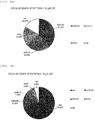
- a circular graph such as the graph of Pattern 1 in Fig. 8A , can be drawn, making it possible to visually understand an overall picture of the distribution ratio into fractions. Furthermore, based on the quantification results, it is possible to make a scoring peculiar for each drug as described below.
- CDF score calculated an example of a CDF score calculated will be shown.
- the score calculated is not limited thereto.
- a score for assessing a blood-vessel-side discharge via a transporter is obtained by
- CDF is a drug that has a property of being more likely to be excreted into a bile duct and less likely to be discharged to the blood vessel side, as compared with Rhodamine 123.
- Example 2 determination of a distribution ratio into fractions and scoring based on measurement results will be explained in the case of using a different method from that in Example 1.
- This case is referred to as "Pattern 2".
- the 9 kinds (S1, S2, S3, B1, B2, B3, C1, C2, and C3) determined by the testing sections of Step 4, 5, and 6 can be used as indices for assessment.
- the distribution ratio into the fractions as shown in Pattern 2 of Fig. 7 can be obtained. From the values, • the first blood-vessel-side discharge fraction (Sup fraction) is associated to S1 ( ⁇ S2 ⁇ S3),
- Example 1 This matches the assessment of the intracellular retention fraction in Example 1. Furthermore, based on the quantification results, a scoring peculiar for the drug can be made, which is as shown in Example 1.
- Example 3 an example of a device for realizing automation of a series of steps described in Example 1 and 2 will be described. Incidentally, descriptions of the purpose of the operation of the device described below, the role of the component thereof, and the like may be sometimes omitted when they are the same as in Example 1 or 2.
- the areas for retaining cells set for the respective Testing sections 1 to 3 shown in Examples 1 to 2 are explained with expressions of a "well for Testing section 1", “well for Testing section 2", “well for Testing section 3", and the like.
- a plurality of containers each of which is the aforementioned "well culture plate” are set for the respective testing sections, or a plurality of wells in one well culture plate may be partitioned to set the partitioned areas as, for example, "a first container", “a second container”, “a third container”, and the like.
- the 4-cell fraction (Testing section 4) explained in Example 1 described above is another "fourth container” that is different from the first to third containers.
- the well for Testing section 1 and the well for Testing section 2 are adjusted to almost the same temperature, a more efficient assessment can be achieved in terms of the accuracy and speed when the sections are set by partitioning one well culture plate.
- the well in the operation of the device described later, as for an operation for replacing a well (container) for each testing section, the well may be replaced automatically or by hand.
- the replacement and install operations of the containers are omitted in the following explanation.
- this device is composed of a culturing unit 106, a sample preparation unit 107 (including an input unit 107A), an analysis unit 108, and a display unit 109. Furthermore, the sample preparation unit 107 includes a temperature regulation unit 107B for regulating temperatures inside containers (plate(s)) described later, a liquid feeding unit 107C capable of feeding or collecting a liquid to or from the containers, and the like.
- the sample preparation unit is desirably under an environment of 5% CO2 and 37°C.
- the analysis unit 108 includes a measurement unit 108A for measuring amounts of a component such as a drug and an analyzing unit 108B for analyzing the amounts of fractions discharged via a transporter and via a bile duct, remaining in cells, and discharged from other paths than the transporter and the bile duct (diffusion) from the amounts of the component such as a drug obtained by the measurement unit.
- the device configuration is an example, and, for example, a configuration in which the analyzing unit is implemented by another device, to which information obtained by the measurement unit is sent, may be obviously employed.
- the sample preparation unit has a role of automatically preparing the fractions to be analyzed.
- FIG. 13 An automated measurement device operation flow chart is shown in Fig. 13 .
- the flowchart of Fig. 13 is merely an example, and as described in Example 1, ⁇ step 2>, in the case where the drug is administered at a different time, the flowchart is not limited thereto.
- a plate including multiple cell retention areas (wells) is used as an example of a container for retaining cells, but the container is obviously not limited to a plate as long as it can retain cells.
- a liver cell tissue is cultured in the culturing unit 106 ( Fig. 10 , Fig. 13A , Sub-step 1). Then, the plate retaining the cultured liver cell tissue is transferred onto a first temperature-regulating-function-equipped plate holder 210 and a second temperature-regulating-function-equipped plate holder (211) of a sample preparation unit ( Fig. 10 , Fig. 13A , Sub-step 2).
- a suction head 205 which is placed in the liquid feeding unit 107C and provided with a suction nozzle for sucking a liquid is moved to a well 002 on a culture plate 001 filled with a medium to be removed, on the plate holder, and sucks the medium from the well to remove the whole amount ( Fig. 13A , Sub-step 3).
- the medium removed is collected for disposal in a waste liquid tank 206.
- a chip 302 for retaining a liquid 301 is attached to a chip head 204 mounted on the suction nozzle from a chip rack 207 storing a plurality of chips.
- the chip head moves to a normal temperature drug solution rack 209, and sucks a buffer ( Fig. 13A , Sub-step 4).
- the chip head moves to a target well, adds the buffer ( Fig. 13A , Sub-step 5), and then moves to a dust box 214 to discard the chip.
- replaceable chips are used here for preventing contamination, the present invention is not limited thereto.
- the suction head moves to the well filled with the buffer and removes the buffer ( Fig. 13A , Sub-step 6).
- the removed medium is collected for disposal into the waste liquid tank 206. This step is repeated twice in total (washing step) ( Fig. 13A , Sub-step 7).
- a chip in the chip rack 207 is attached to the chip head 204, and the chip head moves to the normal temperature drug solution rack 209 and sucks the buffer ( Fig. 13A , Sub-step 8).
- the chip head moves to the target well, adds the buffer, and then moves to the dust box 214 to discard the chip.
- the device waits at 37°C for 10 minutes (conditioning) ( Fig. 13A , Sub-step 9).
- the suction head 205 moves to the well filled with the buffer, and removes the whole amount of the buffer ( Fig. 13A , Sub-step 10).
- a chip in the chip rack 207 is attached to the chip head 204, and the chip head moves to the normal temperature drug solution rack 209, and sucks a drug solution ( Fig. 13A , Sub-step 11).
- the chip head 204 moves to the target well, adds the drug solution ( Fig. 13A , Sub-step 12), and then moves to the dust box 214 to discard the chip.
- the device waits at 37°C for 30 minutes ( Fig. 13A , Sub-step 12).
- the first temperature-regulating-function-equipped plate holder 210 and the second temperature-regulating-function-equipped plate holder 211 which constitute one configuration example of the container retention unit for retaining containers, change from 37°C to 4°C ( Fig. 13A , Sub-step 13), then the suction head 205 moves to the well filled with the drug solution, and removes the whole amount of the drug solution ( Fig. 13A , Sub-step 14).
- the temperature regulation unit in this example a plate holder is equipped with a temperature regulating function in this explanation, but the temperature regulation unit may obviously be present separately from the container retention unit.
- a chip in the chip rack 207 is attached to the chip head 204, and the chip head moves to the cold-stored drug solution rack 208 and sucks a buffer ( Fig. 13A , Sub-step 15).
- the reason why a cold-stored drug solution is used is to stop an active biological phenomenon such as a transporter activity, as described above.
- the cold-stored drug solution rack 208 is intended for keeping a drug solution, a buffer, or the like at a low temperature for this purpose.
- the chip head 204 moves to the target well, adds the buffer thereto ( Fig. 13A , Sub-step 16), and then moves to the dust box 214 to discard the chip.
- the suction head moves to he well filled with the buffer, and removes the buffer ( Fig. 13A , Sub-step 17).
- the removed medium is discarded into the waste liquid tank 206. This step is repeated 3 times in total (washing step) ( Fig. 13A , Sub-step 18).
- a chip in the chip rack 207 is attached to the chip head 204, the chip head moves to the cold-stored drug solution rack 208, and sucks the buffer ( Fig. 13A , Sub-step 20).
- the chip head 204 moves to the target well, adds the buffer ( Fig. 13A , Sub-step 21), and then moves to the dust box 214 to discard the chip.
- the device waits at 37°C for 30 minutes ( Fig. 13A , Sub-step 20). Then, the first temperature-regulating-function-equipped plate holder 210 and the second temperature-regulating-function-equipped plate holder 211 change from 37°C to 4°C ( Fig. 13A , Sub-step 22). Then, a chip in the chip rack 207 is attached to the chip head 204, moves to the well filled with the buffer containing the drug, sucks the drug-containing buffer (supernatant), and dispenses the supernatant to a collection plate for collection on the first plate holder 212 and the second plate holder 213 (collection) ( Fig. 13A , Sub-step 23).
- the chip head 204 moves to a well for Testing section 4 on the first temperature-regulating-function-equipped plate holder (210), adds the 1% TritonX-100 or pure water/methanol ( Fig. 14 , Sub-step 21), and then moves to the dust box 214 to discard the chip.
- a chip in the chip rack 207 is attached to the chip head 204, moves to the well filled with the aforementioned reagent, sucks the whole amount of the cell suspension, and dispenses the cell suspension into the collection plate for collection on the first plate holder 212 (collection) ( Fig. 14 , Sub-step 22).
- the chip head moves to a well for Testing section 4 on the first temperature-regulating-function-equipped plate holder (210), adds the trypsin/EDTA, and then the device waits at 37°C for 30 minutes ( Fig. 15B , Sub-step 21).
- the chip head sucks 1% TritonX-100 or pure water/methanol ( Fig. 15B , Sub-step 22).
- the chip head 204 moves to the well for Testing section 4 on the first temperature-regulating-function-equipped plate holder (210), adds the 1% TritonX-100 or pure water/methanol ( Fig. 15B , Sub-step 23), and then moves to the dust box 214 to discard the chip.
- a chip in the chip rack 207 is attached to the chip head 204, moves to the well filled with the aforementioned reagent, sucks the whole amount of the cell suspension, and dispenses the cell suspension into the collection plate for collection on the first plate holder 212 (collection) ( Fig. 15B , Sub-step 24).
- the chip head 204 moves to a well for Testing section 1 on the first plate holder 212, adds the buffer containing EGTA ( Fig. 13B , Sub-step 26), and then moves to the dust box 214 to discard the chip.
- the device waits at 37°C for 30 minutes ( Fig. 13B , Sub-step 26).
- a chip in the chip rack 207 is attached to the chip head 204, and the chip head moves to the normal temperature drug solution rack 209, and sucks a buffer ( Fig. 13B , Sub-step 27).
- the chip head 204 moves to a well for Testing section 2 on the first plate holder 212, adds the buffer ( Fig. 13B , Sub-step 28), and then moves to the dust box 214 to discard the chip.
- the device waits at 37°C for 30 minutes ( Fig. 13B , Sub-step 28) .
- a chip in the chip rack 207 is attached to the chip head 204, and the chip head moves to the cold-stored drug solution rack 209, and sucks a buffer ( Fig. 13B , Sub-step 29).
- the chip head 204 moves to a well for Testing section 3 on the second plate holder 213, adds the buffer ( Fig. 13B , Sub-step 30), and then moves to the dust box 214 to discard the chip.
- the device waits at 4°C for 30 minutes ( Fig. 13B , Sub-step 30).
- a chip in the chip rack 207 is attached to the chip head 204, moves to the well filled with the EGTA buffer containing the drug, sucks the drug-containing EGTA buffer (supernatant), and dispenses (collects) the supernatant into the collection plate for collection on the first plate holder 212 ( Fig. 13B , Sub-step 31).
- a chip in the chip rack 207 is attached to the chip head 204, moves to the well filled with the buffer containing the drug, sucks the drug-containing buffer (supernatant), and dispenses (collects) the supernatant into the collection plate for collection on the first plate holder 212 ( Fig. 13B , Sub-step 32).
- a chip in the chip rack 207 is attached to the chip head 204, moves to the well filled with the EGTA buffer containing the drug, sucks the drug-containing buffer (supernatant), dispenses (collects) the supernatant into the collection plate for collection on the first plate holder 213 ( Fig. 13B , Sub-step 33).
- a chip in the chip rack 207 is attached to the chip head 204, the chip head moves to the normal temperature drug solution rack 209, and sucks 1% TritonX-100 or pure water/methanol ( Fig. 13B , Sub-step 35).
- the chip head 204 moves to the well for each of Testing sections 1, 2, and 3 on the first temperature-regulating-function-equipped plate holder (210) and the second temperature-regulating-function-equipped plate holder 211, adds the 1% TritonX-100 or pure water/methanol ( Fig. 13B , Sub-step 36), and then moves to the dust box 214 to discard the chip.
- a chip in the chip rack 207 is attached to the chip head 204, moves to the well filled with the aforementioned reagent, sucks the whole amount of the cell suspension, and dispenses the cell suspension into the collection plate for collection on the first plate holder 212 and the second plate holder 213 (collection) ( Fig. 13B , Sub-step 37).
- operations in the steps of Testing sections 1 to 3 in Examples 1 and 2 are sequentially performed, but the steps may be performed sequentially or in parallel.
- a chip in the chip rack 207 is attached to the chip head 204, and the chip head moves to the normal temperature drug solution rack (209), and sucks a buffer containing trypsin/EDTA ( Fig. 16B , Sub-step 25).
- the chip head 204 moves to a well for Testing section 1 on the first plate holder 212, adds the buffer containing trypsin/EDTA ( Fig. 16B , Sub-step 26), and moves to the dust box 214 to discard the chip.
- the device waits at 37°C for 30 minutes ( Fig. 16B , Sub-step 26).
- a chip in the chip rack 207 is attached to the chip head 204, and the chip head moves to the normal temperature drug solution rack 209, and sucks a buffer ( Fig. 16B , Sub-step 27).
- the chip head 204 moves to a well for Testing section 2 on the first plate holder 212, adds the buffer ( Fig. 16B , Sub-step 28), and then moves to the dust box 214 to discard the chip.
- the device waits at 37°C for 30 minutes ( Fig. 16B , Sub-step 28).
- a chip in the chip rack 207 is attached to the chip head 204, and the chip head moves to the cold-stored drug solution rack 209, and sucks a buffer ( Fig. 16B , Sub-step 29).
- the chip head 204 moves to a well for Testing section 3 on the second plate holder 213, adds the buffer ( Fig. 16B , Sub-step 30), and then moves to the dust box 214 to discard the chip.
- the device waits at 4°C for 30 minutes ( Fig. 16B , Sub-step 30).
- a chip in the chip rack 207 is attached to the chip head 204, moves to the well filled with the trypsin/EDTA buffer containing the drug, sucks the cell suspension, and dispenses (collects) the cell suspension into the collection plate for collection on the first plate holder 212 ( Fig. 16B , Sub-step 31).
- the dispensed plate is subjected to centrifugation in a centrifugation unit to separate into a supernatant and a cell pellet, and then the supernatant is dispensed (collected) into the collection plate for collection on the first plate holder 212 ( Fig. 16B , Sub-step 32).
- centrifugation is used here, the method is obviously not limited thereto as long as it can separate the supernatant and the pellet.
- a chip in the chip rack 207 is attached to the chip head 204, and the chip head 204 moves to the well filled with the buffer containing the drug, sucks the drug-containing buffer (supernatant), and dispenses (collects) the supernatant into the collection plate for collection on the first plate holder 212 ( Fig. 16B , Sub-step 33).
- a chip in the chip rack 207 is attached to the chip head 204, and the chip head 204 moves to the well filled with the buffer containing the drug, sucks the drug-containing buffer (supernatant), dispenses (collects) the supernatant into the collection plate for collection on the first plate holder 213 ( Fig. 16B , Sub-step 34).
- a chip in the chip rack 207 is attached to the chip head 204, and the chip head 204 moves to the normal temperature drug solution rack 209, and sucks 1% TritonX-100 or pure water/methanol ( Fig. 16B , Sub-step 36).
- the chip head 204 moves to the well for each of Testing sections 1, 2, and 3 on the first temperature-regulating-function-equipped plate holder (210) and the second temperature-regulating-function-equipped plate holder 211, adds the 1% TritonX-100 or pure water/methanol ( Fig. 16B , Sub-step 37), and then moves to the dust box 214 to discard the chip.
- a chip in the chip rack 207 is attached to the chip head 204, moves to the well filled with the aforementioned reagent, sucks the whole amount of a cell suspension, and dispenses the cell suspension into the collection plate for collection on the first plate holder 212 and the second plate holder 213 (collection) ( Fig. 16B , Sub-step 38).
- the drug collected on the culture plates is transferred to a measurement unit ( Fig. 13B , Sub-step 38).
- the drug is measured by a plate reader or an LCMS ( Fig. 13B , Sub-step 39).
- the component analysis device further comprising a temperature regulation unit for regulating a temperature of a liquid in the plurality of containers, wherein the plurality of containers are at least a first container, a second container, and a third container, wherein the third container retains the buffer solution, and wherein the temperature regulation unit makes regulation so that a second temperature inside the third container is lower than a first temperature inside the first container and inside the second container, and wherein the analysis unit measures an amount of the component discharged from the liver cell tissue in the third container to the buffer solution in the third container, and analyzes an amount of the component to be discharged via a transporter of the liver cell tissue and an amount of the component to be discharged from other paths than the transporter and the bile duct in the liver cell tissue.
- a temperature regulation unit for regulating a temperature of a liquid in the plurality of containers, wherein the plurality of containers are at least a first container, a second container, and a third container, wherein the third container retains the buffer solution, and wherein the temperature regulation unit
- It is drug component analysis device comprising a retention unit for retaining a plurality of containers for retaining a liver cell tissue having a drug absorbed therein, a liquid feeding unit for feeding a liquid in the plurality of containers, a temperature regulation unit for regulating a temperature of a liquid in the plurality of containers, and an analysis unit for measuring amounts of the drug in the plurality of containers and analyzing the drug thus measured, wherein the plurality of containers are a first container, a second container, a third container, and a fourth container, wherein the liquid feeding unit feeds a first solution containing a substance that releases adhesion between multiple cells forming the liver cell tissue into the fourth container, feeds the first solution into the first container, and feeds a buffer solution into the second container and the third container, wherein the temperature regulation unit regulates a temperature so that a temperature inside the third container is lower than a temperature inside the first container and inside the second container, and wherein the analysis unit analyzes an amount of the drug discharged from the liver cell tissue in the first container to the
- It is a component analysis method including an analyzing step for measuring a component fed into a plurality of containers retaining a liver cell tissue and analyzing the component thus measured, wherein the plurality of containers are at least a first container and a second container, wherein the first container retains a first solution containing a substance that releases adhesion between multiple of cells forming the liver cell tissue, and wherein the second container retains a buffer solution, and wherein in the analyzing step, an amount of the component discharged from the liver cell tissue in the first container into the first solution and an amount of the component discharged from the liver cell tissue in the second container into the buffer solution in the second container are measured and an amount of the component to be discharged via a bile duct in the liver cell tissue is analyzed.
- It is a drug component analysis method comprising a liquid feeding step for feeding a liquid in a plurality of containers retaining a liver cell tissue having a drug absorbed therein, a temperature regulating step for regulating a temperature of a liquid in the plurality of container, and an analyzing step for measuring amounts of the drug in the plurality of containers and analyzing the drug thus measured, wherein the plurality of containers are a first container, a second container, a third container, and a fourth container, wherein in the liquid feeding step, a first solution containing a substance that releases adhesion between multiple cells forming the liver cell tissue is fed to the fourth container, the first solution is fed to the first container, and a buffer solution is fed to the second container and the third container, wherein in the temperature regulating step, a temperature is regulated so that the temperature inside the third container becomes lower than a temperature inside the first container and inside the second container, and wherein in the analyzing step, an amount of the drug discharged from the liver cell tissue in the first container into the first solution, an
Landscapes
- Health & Medical Sciences (AREA)
- Life Sciences & Earth Sciences (AREA)
- Engineering & Computer Science (AREA)
- Chemical & Material Sciences (AREA)
- Biomedical Technology (AREA)
- Bioinformatics & Cheminformatics (AREA)
- Immunology (AREA)
- Zoology (AREA)
- Organic Chemistry (AREA)
- Wood Science & Technology (AREA)
- Biotechnology (AREA)
- Microbiology (AREA)
- General Health & Medical Sciences (AREA)
- Biochemistry (AREA)
- Molecular Biology (AREA)
- Hematology (AREA)
- Urology & Nephrology (AREA)
- Genetics & Genomics (AREA)
- Toxicology (AREA)
- Cell Biology (AREA)
- General Engineering & Computer Science (AREA)
- Sustainable Development (AREA)
- Analytical Chemistry (AREA)
- Medicinal Chemistry (AREA)
- Physics & Mathematics (AREA)
- Tropical Medicine & Parasitology (AREA)
- Food Science & Technology (AREA)
- General Physics & Mathematics (AREA)
- Pathology (AREA)
- Gastroenterology & Hepatology (AREA)
- Clinical Laboratory Science (AREA)
- Measuring Or Testing Involving Enzymes Or Micro-Organisms (AREA)
- Apparatus Associated With Microorganisms And Enzymes (AREA)
- Investigating Or Analysing Biological Materials (AREA)
Abstract
Description
- The present invention relates to an assessment in vitro (outside the body) of an overall picture of pharmacokinetics, such as uptake, metabolism, and excretion, of a medicament, useful for new drug development.
- In the process of new drug development, a clinical trial ("human clinical trial") in which a drug is administered to human bodies to verify the efficacy is necessarily performed under the Pharmaceutical Affairs Act. However, a human clinical trial and an animal experiment trial require an enormous development expense. In recent years, the entire cost for new drug development has increased due mainly to such a development expense. One of main causes thereof is the fact that in the case of a drug candidate whose short medical efficacy and whose toxicity are not able to be detected in non-clinical animal experiments in an early phase of the development process, but found only in a human clinical trial in a latter phase of the development process, the previous development expenses and the expenses for the human clinical trial go to waste.
- Against the background, in order to increase a pass rate of a human clinical trial to reduce the cost for new drug development, it is important to screen a new drug candidate substance that has a medical efficacy and does not show toxicity, in an early phase. Thus, many pharmaceutical companies demand an assessment system in vitro (outside the body) in which, in an early phase of a drug discovery, a drug candidate is not screened only by an animal experiment which has a small correlation with the characteristics of human cells, but pharmacokinetics of an administered medicament in human bodies can be successfully predicted using human cells.
- However, a technique for grasping and dissecting an overall picture of pharmacokinetics, such as uptake, metabolism, and bile duct and blood vessel excretions, of an administered pharmaceutical candidate compound by utilizing the cells has not been established yet. In order for a drug to exhibit a medical efficacy in the body, the drug once taken into a liver is required, after being converted into a metabolism product or in a form of the original compound (parent compound) as it is without undergoing metabolism, to be discharged into a blood vessel side and then recirculate through the bloodstream again to reach a target organ or part.
- Accordingly, also in a trial system in vitro, if the recirculating amount of a pharmaceutical candidate compound discharged to the blood vessel side after administration can be measured to assess the medical efficacy which is one of the most important indices in the new drug development, such a measurement can be a very useful assessment method of pharmacokinetics. In addition, by grasping an overall picture of pharmacokinetics including an amount of the compound excreted from the cells to the bile duct (elimination amount), which is then excreted out of the body with urine or feces after the bile duct excretion and an amount of the compound retained in the cells, it becomes possible to determine a distribution ratio into fractions.
-
PTL 1 andPTL 2 have previously disclosed a technique in which a drug is administered to cultured cells to assess an amount excreted from the bile duct of the cells (elimination amount). This assessment method assesses a drug elimination amount which is an amount of the administered drug that is excreted into the bile duct without exhibiting toxicity or a medical efficacy, and then excreted out of the body with urine or feces. -
- PTL 1: Japanese Patent Publication No.
2012-65659 - PTL 2: Japanese Patent Publication No.
8-503610 - The prior art techniques were methods which assesse a bile duct excretion amount, namely, an amount of a component that has no medical efficacy, that is, methods for assessing the out-of-body-elimination amount. However, in order to obtain information of a component having a medical efficacy, it is desired to directly assess the amount of the component excreted to the blood vessel side. In the prior art, however, a method for analyzing an amount of a compound excreted into blood vessels has not been established. Furthermore, there has not been any established assessment method in which not only a part of pharmacokinetics can be assessed, but also an overall picture of pharmacokinetics in vitro can be provided to achieve a medical efficacy assessment with a higher accuracy, by dividing an administered drug into fractions and quantifying the fractions, such as a blood-vessel (basal/basolateral)-side discharge fraction, a lumen (apical)-side discharge fraction, and an intracellular retention fraction, to determine where the administered drug is excreted from and where the drug is retained in.
- For example, provided is a component analysis device, including a retention unit for retaining a plurality of containers for retaining a liver cell tissue and an analysis unit for measuring a component fed to the plurality of containers and analyzing the component thus measured, wherein the plurality of containers are at least a first container and a second container, wherein the first container retains a first solution containing a substance that releases adhesion between multiple cells forming the liver cell tissue, and the second container retains a buffer liquid, and wherein the analysis unit measures an amount of the component discharged from the liver cell tissue in the first container into the first solution and an amount of the component discharged from the liver cell tissue in the second container into the buffer liquid in the second container, to analyze an amount of the component to be discharged via a bile duct in the liver cell tissue.
- By applying the present invention, a component, such as a drug, excreted to the blood vessel side of the cells can be accessed in a direct manner. Furthermore, a blood-vessel (basal/basolateral)-side discharge fraction via a transporter and via diffusion, a lumen (apical)-side discharge fraction, and an intracellular retention fraction, of a pharmaceutical candidate compound (parent compound and metabolism product) are quantified, and the total amount of the administered pharmaceutical candidate compound and a distribution ratio into fractions are determined, whereby kinetics of the administered pharmaceutical candidate compound can be assessed, an accuracy in screening in vitro a drug candidate exhibiting a medical efficacy from among a huge number of pharmaceutical candidate compounds can be enhanced. As a result, it becomes possible to screen a pharmaceutical candidate compound in an early phase, and to reduce a wasted animal experiment and an unnecessary human clinical trial. The present invention contributes to reduction of new drug development cost which places a burden on pharmaceutical companies.
-
-
Fig. 1 shows a culture plate. -
Fig. 2 shows a sample preparation flow. -
Fig. 3 shows objects to be quantified and medicament distribution image views forSteps -
Fig. 4 shows a flow with 4-cell. -
Fig. 5 shows a collection rates by a new protocol. -
Fig. 6A shows fluorescence intensities of a collected drug inTesting section 1,Step 5. -
Fig. 6B shows fluorescence intensities of a collected drug inTesting section 1,step 5. -
Fig. 6C shows an effect of a dispersed drug. -
Fig. 6D shows an effect of a dispersed drug. -
Fig. 6E shows an effect of a dispersed drug. -
Fig. 6F shows an effect of a dispersed drug. -
Fig. 6G shows an effect of a dispersed drug. -
Fig. 6H shows an effect of a dispersed drug. -
Fig. 6I shows an effect of a dispersed drug. -
Fig. 6J shows an effect of a dispersed drug. -
Fig. 6K shows an effect of a dispersed drug. -
Fig. 6L shows an effect of a dispersed drug. -
Fig. 7 shows definitions of fractions and results for CDF. -
Fig. 8A shows a distribution ratio of CDF. -
Fig. 8B shows a distribution ratio of CDF. -
Fig. 9A shows a distribution ratio of Rhodamine 123. -
Fig. 9B shows a distribution ratio of Rhodamine 123. -
Fig. 10 shows an automated measurement device configuration diagram. -
Fig. 11 shows a sample preparation unit top view. -
Fig. 12 shows a sample preparation unit front view. -
Fig. 13A shows an automated measurement device operation flow chart. -
Fig. 13B shows an automated measurement device operation flow chart. -
Fig. 14 shows an automated measurement device operation flow chart. -
Fig. 15A shows an automated measurement device operation flow chart. -
Fig. 15B shows an automated measurement device operation flow chart. -
Fig. 16A shows an automated measurement device operation flow chart. -
Fig. 16B shows an automated measurement device operation flow chart. -
Fig. 17 shows a chip head and a chip. - In this example, a component analysis method for the medical efficacy assessment described above will be explained along
Steps 0 to 6 inFig. 2 .Steps 4 to 6 will be described in detail with reference toFig. 3 . Incidentally, in the following plural examples, although an explanation will be made based on an assessment method of a medicinal efficacious ingredient, the method is merely an example for explaining the invention of the present application, and the component analysis method of the invention of this application can obviously be applied for assessing any other chemicals than drugs, as well as medicament metabolism products. In addition, specific conditions, such as the buffer liquid, temperature, and time period, shown in this example, are merely examples, and other conditions may obviously be applied as long as they have the same effect in terms of a technical idea. - In this example, a case where at least three testing sections of
Testing Sections 1 to 3 are used is explained. In each testing section, a retention area for retaining cells are present, and in the retention areas, respective containers may be used for respective testing sections, or one container having plural retention areas may be partitioned to set the respective testing sections. - In this step, liver cells are prepared and cultured for verifying an effect of a drug. An example will be shown below. The preparation of liver cells was made according to an in-situ collagenase perfusion method. The detail is as follows. A rat (5 to 6 weeks old) is subjected to laparotomy under pentobarbital anesthesia, and a catheter is inserted into the portal vein and a pre-perfusion fluid (Hanks' solution not containing Ca2+ and Mg2+ but containing EGTA) is injected.
- After thorough blood removal from the liver is confirmed, the perfusion is stopped. The perfusion fluid is replaced with a collagenase solution, and then perfusion is performed. In this example, perfusion is performed using a Hanks' solution containing 0.05% collagenase, but the perfusion fluid is not limited thereto. After digestion of the intercellular tissue by collagenase is confirmed, the perfusion is stopped. The liver is cut out, cut into elongated segments in a cooled Hanks' solution, and dispersed as cells by pipetting. Damaged liver cells are removed by centrifugation of 500G for 5 minutes using isotonic Percoll.
- The viability of the resulting liver cells is measured by the trypan blue exclusion method, liver cells of a viability of 85% or more are used for culture. Although liver cells of a viability of 85% or more are used for culture here, the present invention is obviously not limited to the condition. In addition, preparation of liver cells is not necessarily limited to the in-situ collagenase perfusion method. The liver cells to be used are not limited to those originated in a rat, and the linage of the rat is not limited. Although liver cells were used in this example, the present invention is not limited thereto.
- Liver cells prepared by the in-situ collagenase perfusion method as described above are suspended in a medium, and the liver cells in the suspension at a density of 5 × 10⁵ cells/mL are seeded on a commercially available collagen-coated culture dish, to conduct two dimensional plane culture (for example, sandwich culture). The seeding density, medium,
culture plate 001 are not particularly limited. - The culture plate is shown in
Fig. 1 . Although a 24-well culture plate containing 24 culture areas (wells, 002) is illustrated here, the culture plate is not limited thereto and a container having another shape may be used as long as given cells can be retained therein. - After seeding, culture is started using a CO2 incubator under conditions of 5% CO2 and 37°C. After 18 hours or more elapse, a first medium exchange is performed. Although a medium used for culture from 18 hours after the seeding is not particularly limited, in this example, a medium obtained by excluding FCS from a medium (10%FCS+) to make a medium (herein after medium (FCS-)) and then adding matrigel thereto was used. After that, medium exchange is performed with the medium (FCS-) every 24 hours.
- In addition, in a case where cells are cultured in a three-dimensional spheroid, that is, in this example, in a case where a three-dimensionally formed liver cell tissue is cultured, a 24-well nanopillar cell culture plate may be used. The number of wells is not particularly limited.
- The cells prepared at a density of 5 × 10⁵ cells/mL are seeded, and then culture is started using a CO2 incubator under conditions of 5% CO2 and 37°C. After 18 hours or more, a first medium exchange is performed. Although a medium used for culture from 18 hours after the seeding is not particularly limited, in this example, a medium obtained by excluding FCS from a medium (10%FCS+) (hereinafter, referred to as medium (FCS-)) was used.
- Although a medium used for culture from 48 hours after the seeding is not particularly limited, in this example, a medium obtained by excluding FCS from a medium (10%FCS+) to make a medium (herein after medium (FCS-)) and then adding matrigel thereto was used. After that, medium exchange is performed with the medium (FCS-) every 24 hours.
- As described later, since tests under different three types of conditions are conducted in Step 5 (described in detail in
Testing sections Steps 0 to 4 andStep 5, the same testing operation is conducted for three types of testing sections. - In this step, cells cultured in
Step 0 are conditioned to a condition suitable for a drug assessment. An example will be shown below. The culture supernatant of cells cultured for 4 days inStep 0 is removed, 400·L of a Hanks' solution is added as a buffer, and then incubation is performed at 37°C for 10 minutes (Fig. 2 , Step 1). - The kinds and amount of the buffer is not particularly limited. The operation of
Step 1 is desirably repeated twice. When a component in which the cells settle is replaced from a medium used in culture inStep 0 into a buffer liquid (for example, Hanks' solution) in this manner, a groundwork can be prepared for conducting accurate measurement and dissection in the subsequent steps. However, the number of repetitions ofStep 1 may obviously be arbitrarily changed depending on the kinds of the buffer liquid and the cells used. - In this step, a drug solution to be assessed is administered to cells. An example will be shown below. After removing the buffer, 200 µL of 10 µM CDF (fluorescent reagent) is added to a well, incubation is performed at 37°C for 30 minutes, the well is then retained at 4°C for 5 minutes (
Fig. 2 , Step 2) . - The kind, concentration, and amount of the reagent are not particularly limited. CDF emits fluorescence, and therefore can be easily quantified by a plate reader as a model reagent. In addition, the administered amount, which was 200 µL, was selected as such an amount that allows for all the cells in the well to be immersed in the reagent. The amount is not limited to such an amount as long as all the cells are immersed in the reagent. The CDF concentration may be any concentration that has been heretofore used in a fluorescent assay of a cell. The above concentration is desirably applied in terms of the amount of reagent for detection with a plate reader. The time period of the incubation, which was 30 minutes, was adopted based on a result of a previous study in which a time period for reaching a significant equilibrium condition in the drug intake-discharge rate was 30 minutes. The time period is not limited but depends on the purpose, and plural time periods may be combined. In addition, incubation is desirably performed using a CO2 incubator under conditions of 5% CO2 and 37°C, as with the case of
Step 0. - For the purpose of preventing the administered drug from leaking outside the cells, after the incubation for 30 minutes, the plate temperature was lowered to 4°C. This is conducted for causing a phenomenon that a cell suppresses discharge of a drug to the outside when the temperature inside the container is lowered.
- By lowering the temperature of the drug to a prescribed temperature or lower in this manner, the drug remains in the cells, and the phenomenon of the drug leaking out of the cells can be suppressed. The temperature, which was 4°C in this example, is not limited thereto as long as leaking of the administered drug out of the cells can be suppressed.
- In addition, the method for suppressing leaking of the administered drug out of the cells is not limited to the method of lowering the temperature if another method, for example, a method of administering an inhibitor, can be applied. In any methods, the temperature for preventing discharge or leaking of the administered drug out of cells is lower than the plate temperature upon administering the drug solution (for example, 37°C). It is because uptake of the administered drug solution into cells is a biological phenomenon, which is considered to be typically activated at 37°C.
- The timing of the drug administration is not limited to this example. For example, the drug administration is sometimes started on the day before the test day or several days earlier. In this case, the drug may be administered at
Step 0 to omitSteps - In this step, any other substances than the drug solution retained in the cells are washed off by
Step 3. An example will be explained below. Next, while holding the plate at 4°C, cells are washed with 400 µL of an ice-cooled Hanks'solution 3 times (Fig. 2 , Step 3). - The reason of 4°C is the same as described above. The amount of the medium in culturing was 400 µL, and for the purpose of removing a medium component remaining on the inside wall of the well, the amount of the washing Hanks' solution was set to 400 µL. The number of times of washing in an ordinary biochemical assay, which is typically three, was followed here. The conditions of washing amount, number of times of washing, or the like are not limited. In this manner, it is possible to remove any other substances than the drug solution to be measured to enhance the accuracy of the medical efficacy assessment in the subsequent steps.
- As one index for assessing a medical efficacy, it is effective to analyze whether an administered drug is likely to remain in cells for a long period of time or for only a short period. Thus, in this step, in order to acquire data for the index, prior to an assessment of cells in each testing section in
Step 5 described later, the drug is leaked from cells for a predetermined time. An example will be shown below. First, a buffer liquid for a pretreatment (for example, Hanks' solution) was administered, incubation was performed at 37°C for 30 minutes, and the Hanks' solution containing the drug (supernatant) was collected (Fig. 2 , step 4). - The incubation time is defined depending on the used drug and the purpose, and is not limited to 30 minutes as in this Example. In addition, the incubation is desirably performed using a CO2 incubator under conditions of 5% CO2 and 37°C, as with the case of
Step 0. As for the buffer liquid, a buffer liquid of the same kind as one used instep 5 may be used, or one of other kinds may be used. - In order to discharge the drug that had been retained in the liver cell tissue (
Fig. 3 , 101) untilStep 3 into the Hanks' solution through first blood-vessel-side discharge, that is, via passive diffusion (Fig. 2 ,Step 4, (1)') and via a transporter (TP) (Fig. 2 ,Step 4, (2)' and 102 in the image view), the temperature was maintained at 37°C. As described later, since blood-vessel-side discharge is performed also inStep 5, for discriminating them, the blood-vessel-side discharge inStep 4 was defined as the first blood-vessel-side discharge, and the blood-vessel-side discharge inStep 5 was defined as a second blood-vessel-side discharge. - Essentially, both of the steps are a step for discharge from cells to the blood vessel side (basal/basolateral) (supernatant). Alternatively, depending on the purpose,
Step 4 can be considered as a washing step prior to the collection step byStep 5. A transporter is a membrane protein that is expressed on a cell membrane and has a function to transport a substance. A transporter plays a role of active substance transportation between the inside and the outside of a cell. - In addition, the passive diffusion is discharge out of the cell not through a transporter, including leaking from a cell membrane, or the like. The reason why the drug discharged into the Hanks' solution is defined as the blood-vessel-side discharge fraction in
step 4 is that the top surface portion of the cell facing the Hanks' solution corresponds to a basal/basolateral surface (Fig. 3 , 104), which is assumed to be a part facing a blood vessel in the body. -
Step 5 explained below is a step for collecting the drug by different 3 kinds of operations (Testing sections step 5, the first blood-vessel-side discharge fraction (a drug discharged into the Hanks' solution) in advance inStep 4 as described above, an index for verifying whether or not the drug is apt to remain in the cell can be acquired. - Incidentally, as the Hanks' solution used for grasping the blood-vessel-side discharge fraction, the Hanks' solution of any testing section may be used. For example, all the Hanks' solutions for
Testing sections 1 to 3 may be assessed or only a part thereof may be used. In addition, Steps 3 and 4 are steps for performing the analysis of the present invention in more detail to achieve a highly accurate assessment, and these steps may obviously be skipped to perform an operation ofStep 5. -
Steps 0 to 4 described above are, as shown inFig. 2 , performed at least inTesting sections 1 to 3. InStep 5, in order to acquire plural index data to be determined in the present invention by analysis described later, in each ofTesting sections 1 to 3, a treatment under a different condition is performed. An example ofStep 5 will be shown below. - On the other hand, for quantifying the total amount of the drug administered to cells, some other cells than the cells used in
Testing sections 1 to 3 are separately provided in advance, and a step for breaking the cells and collecting a cell extract solution was added betweenStep 3 and Step 4 (Step 4.0,Fig. 4 ). - A fraction obtained in this step is referred to as a 4-cell fraction. The 4-cell fraction corresponds to a container which is separately provided from the containers used in
Testing sections 1 to 3, that is corresponds to a sort ofTesting section 4. By adding this step, it is possible to determine the collection rate of the drug from the sum of the drug amounts collected inTesting sections 1 to 3 in thesubsequent Steps Testing section 4. By determining the collection rate of the drug, it is possible to assess the drug intake-discharge rate. - In the case of a fluorescence measurement, for example, either in a 2D structure such as sandwich culture or in a 3D structure such as spheroid, the drug collection and measurement of the fluorescence intensity can be performed by following the collection protocol for fluorescence measurement shown in
Fig. 2 ,Step 6. - In addition, also in an LCMS measurement, for example, in the case of a 2D structure such as sandwich culture, the drug collection and LCMS measurement can be performed by following the collection protocol for LCMS measurement shown in
Fig. 2 ,Step 6. - On the other hand, in the case of a 3D structure such as spheroid, collection of the whole amount of the drug has been difficult even with the collection protocol for LCMS measurement shown in
Fig. 2 ,Step 6. Accordingly, a protocol in which trypsin/EDTA is added as described in Step 4.0 inFig. 4 has been devised. - This aims at cutting an intercellular adhered protein by trypsin which is a proteinase to degrade spheroid into single cells, facilitating access with water and methanol, and thereby extracting the intracellular fraction efficiently.
- The reagent is not limited to this reagent as long as it can release intercellular adhesion in a structure in which cells are three dimensionally arranged such as spheroid to degrade the structure into the single cells. In addition, the reagent may be any reagent that can extract the intracellular fraction in a 3D structure even not through degrading the structure into the single cells, and can be applied to a liquid chromatography mass spectrometry (LCMS) measurement. An example in which 10 µM of Rosuvastatin is administered to cells and a LCMS measurement is performed to assess a drug intake-discharge rate is shown in
Fig. 5 . - The drug intake-discharge rate can be calculated by (
Steps 4+5+6) / 4-Cell × 100. As a result, a collection rate in the case where a 2D structure was subjected to a water and methanol treatment was 92.3%, and a collection rate in the case where the 2D structure was subjected to a trypsin treatment, followed by a water and methanol treatment was 94.0%. - On the other hand, a collection rate in the case where a 3D spheroid was subjected to the water and methanol treatment was 138%, and a collection rate in the case where the 3D spheroid was subjected to the trypsin treatment, followed by the water and methanol treatment was 92.2%. The reason why the collection rate in the case of a 3D spheroid treated only with water and methanol exceeded 100% was considered as follows: the drug of the 4-cell fraction was not be able to be fully collected only with water and methanol and thus the sum of the drug amounts collected in the
subsequent Steps - As is apparent from the above results, in order to collect the intracellular fraction completely to obtain an precise drug intake-discharge rate, a trypsin treatment is not necessary in a 2D structure, but essential in a 3D spheroid. The reagent is obviously not limited to trypsin/EDTA as long as it is a reagent that releases intercellular adhesion to facilitate degradation into the single cells.
- In
Testing section 1, as illustrated inTesting section 1 ofFig. 3 , the total of the bile-duct-side discharge (3) and the second blood-vessel-side discharge (that is, discharge by diffusion (1) and a transporter (TP) (2)) is discharged from cells into a buffer liquid (for example, Hanks' (-) solution). - The Hanks' (-) solution is a Hanks' solution containing no calcium ion and no magnesium ion, and used in the case, such as this testing section, where intercellular adhesion is intentionally not to be strengthened. In the case of a sandwich culture with a two dimensional plane form, for the purpose of actively releasing intercellular adhesion, a chelator such as EGTA as described later is used.
- Next, 200 µL of the Hanks' (-) solution containing 1 mM of EGTA was added. EGTA has a chelating function for suppressing an action of Ca2+ and Mg2+ which involve in adhesion of intercellular adhesion molecules, and is a reagent for releasing the intercellular adhesion. This allows a bile duct formed in the culture process to collapse.
- After incubation at 37°C for 30 minutes, the supernatant was collected. The incubation is desirably performed using a CO2 incubator under conditions of 5% CO2 and 37°C as with the case of
Step 0. The reagent is not limited to EGTA as long as it has a chelating function. The kind and amount of the buffer containing EGTA and the temperature and time period for the incubation are not particularly limited. - In
Testing section 1 ofStep 5, at the time whenStep 4 is ended, all of the drug retained in the cells (Fig. 3 ,Step 5, and image views (1) and (2)) and the drug discharged into the bile duct (Fig. 3 ,Step 5 and image view (3)) are discharged into the supernatant and collected (Fig. 3 ,Step 5, Testing section 1). - The reason why (3) is defined as a bile-duct-side discharge fraction in
Step 5 is that a cell membrane part around a gap formed in the intercellular adhesion part corresponds to an apical face (Fig. 3 , 105), and that the gap is assumed as a bile canaliculi (Fig. 3 , 103). - In
Step 5,Testing section 1, the temperature is maintained at 37°C, and therefore a fraction discharged from cells into the blood vessel side includes a fraction via passive diffusion (Fig. 3 ,Step 5, (1)) and a fraction via a transporter (Fig. 3 ,Step 5, (2)). In addition, in the case of 3D spheroid culture, since the cells formed several layers or for other reasons, even when the treatment with a buffer containing EGTA was performed for a appropriate time period for a two dimensional sandwich culture, the intercellular adhesion release did not proceed and it was difficult to collect the bile duct discharge fraction (Fig. 6A ). - For this reason, for a 3D spheroid obtained after adding 200 µL of 10 µM of CDF (fluorescent reagent) to a well in
Step 2 and performing incubation at 37°C for 30 minutes, trypsin/EDTA was used inStep 5,Testing section 1. - This was performed for the purpose as follows: since it was considered difficult for only EGTA to release the intercellular adhesion of the 3D structure composed of several layers of cells within an appropriate time period, the intercellular adhesion protein is more actively cut into the single cells with trypsin which is a protease.
- The detail of the protocol is as described in
Fig. 4 ,Testing section 1,Step 5. Results of fluorescence intensity measurements of the supernatant, taken immediately after the buffer administration, and at 2 minutes, 5 minutes, 10 minutes, and 20 minutes after administration are shown inFig. 6B . The case of only the buffer is plotted by ▲, the case of EGTA by ■, the case of trypsin/EDTA by ●. As a result, it was found that, unlike in the case of treatment with only EGTA (■), in the case of treatment with trypsin/EDTA (●), the supernatant-side discharge amount apparently increased (Fig. 6B ). - The reason was considered as follows: as is apparent from the phase contrast microscopic image in
Figs. 6C to 6L , , intercellular adhesion was collapsed by the trypsin/EDTA treatment, and the bile duct discharge fraction was discharged to the supernatant side. This suggests that for completely collecting the bile duct discharge fraction from a 3D spheroid, a treatment for degrading the cells into the single cells is essential. The reagent is obviously not limited to trypsin/EDTA as long as it releases intercellular adhesion to facilitate the degradation into single cells. - In
Testing section 2, the bile duct is not collapsed unlike inTesting section 1 and only a fraction that is called the second blood-vessel-side discharge inFig. 3 (diffusion (1) and transporter (2)) is discharged. The Hanks' solution was added in an amount of 200 µL. SinceTesting section 2 does not contain a chelating agent such as EGTA unlikeTesting section 1, intercellular adhesion remains to be maintained, and therefore, in this testing section, collapse of a bile canaliculi is not induced. - After incubation at 37°C for 30 minutes, the supernatant was collected. The incubation is desirably performed using a CO2 incubator under conditions of 5% CO2 and 37°C as with the case of
Step 0. - In
Testing section 2 ofStep 5, the drug retained in the cells at the time whenStep 4 ends (Fig. 3 ,Step 5, and image view (1), (2)) is discharged into the supernatant and collected (Fig. 3 ,Step 5, Testing section 2). Various conditions are not limited. - According to the foregoing explanations, the drug discharged in the supernatant is defined as the second blood-vessel-side discharge fraction. In
Step 5,Testing section 2, since the temperature is maintained at 37°C, a fraction discharged from cells into the blood vessel side includes a fraction via passive diffusion (Fig. 3 ,Step 5, (1)), and a fraction via a transporter (Fig. 3 ,Step 5, (2)). - By quantitatively analyzing amounts of the drug collected from
Testing section 1 andTesting section 2 ofStep 5, for example, by subtracting a quantified value of the amount of the drug collected inTesting section 2 from a quantified value of the amount of the drug collected inTesting section 1, a drug amount of the bile-duct-side discharge (3) can be calculated. - By making
Testing section 3 in a lower temperature condition thanTesting sections Step 5,Testing section 2 that shares a common point of a maintained system. - This is because the blood-vessel-side discharge via a transporter is suppressed by adopting 4°C. In
Step 5,Testing section 3, by adopting Testing section of a low temperature, 4°C in which a transporter activity is suppressed, it is possible to quantify only a discharge amount via passive diffusion (Fig. 3 ,Step 5, (1)) to calculate (quantify) the blood-vessel-side drug discharge amount via a transporter in comparison withStep 5,Testing section 2. - For each drug, a specific transporter is present for moving inside and outside the cells. Accordingly, the possibility of excluding the discharge amount via passive diffusion and quantifying discharge amount via a transporter means possibility of quantifying a specific discharge amount for each drug. The kind and amount of the buffer, and the temperature and time period of incubation are not particularly limited.
- By quantifying the drug collected from
Testing section 2 andTesting section 3 ofStep 5 in the same manner as described above, the discharge fraction via a transporter can be calculated. Incidentally, an example in whichTesting sections - For example, if only the bile-duct-side discharge (3) and the second blood-vessel-side discharge ((1)+(2)) are desired to be separated, only Testing
sections sections - In addition, by separately providing a 4°C-collapsed system as needed, as for the discharge into the bile-canaliculi-side, discharge via a transporter is suppressed, and only the discharge by diffusion can be measured. This makes it possible to separately assess the discharge into the bile canaliculi side by diffusion and the discharge into the bile canaliculi side via a transporter, for example, by comparing the 4°C-collapsed system with
Testing section 3. The steps in each ofTesting sections 1 to 3 described above may be conducted in any order, or the steps may be conducted in parallel. - In
Step 6, all the three testing sections return into a common operation again. InStep 6, drug collection is performed for quantifying the intracellular retention fraction. In the case where a fluorescence drug or the like is quantified with a plate reader or the like, it is desired that a Hanks' solution containing 1% of a surfactant is added, for example, in an amount of 200 µL, to suspend the cells therein, and the whole amount is collected (Fig. 2 , Step 6). - This makes it possible to break a cell membrane to discharge the drug remaining in the cells. The resulting sample was transferred into a culture plate, and a fluorescence measurement was performed using a plate reader. For a blank measurement, a well in which only a Hanks' solution is added is provided. The fluorescence intensity is measured using an excitation wavelength of 484 nm and an absorption wavelength of 519 nm.
- In addition, when a drug is quantified using a mass spectrometry (LCMS) device, or the like, the drug remaining in cells is extracted through making a hypotonic solution by adding water, a treatment with an organic solvent, or other procedure, and then, the cells are suspended in an organic solvent such as methanol to collect the whole amount (
Fig. 2 , Step 6). - Subsequently, the drug is quantified using a LCMS device as described later. Either in the case of a plate reader measurement of a fluorescence drug as described above, or in the case of a LCMS measurement of a drug, when a 3D spheroid is used as a material, a cell pellet collected after centrifugation in
Testing section 1,Step 5 is subjected to the breaking step described above and the drug is quantified. - Based on fluorescence intensities reflecting the drug amounts obtained in the above steps, a distribution ratio into fractions is calculated. Here, the total sum of
Steps 5 and 6 (Fig. 3 , B# + C# = (1) + (2) + (3) + (4)) is taken as a 100% drug amount. - This case is referred to as "
Pattern 1". From 6 kinds of values determined by the fluorescence amount measurements (B1, B2, B3, C1, C2, and C3), a distribution ratio into fractions as shown inFig. 7 ,Pattern 1 is obtained. From the values, - the second-blood-vessel-side discharge fraction only by diffusion (extracellular efflux by diffusion, ExEfx-Dif) is associated to B3,
- the second-blood-vessel-side discharge fraction only via a transporter (extracellular efflux by transporter, ExEfx-TP) is associated to B2-B3,
- the bile-duct-side discharge fraction (bile canaliculi efflux, BCEfx) is associated to B1-B2,
- the intracellular retention fraction (Cell) is associated to C1.
- Based on the results, a circular graph, such as the graph of
Pattern 1 inFig. 8A , can be drawn, making it possible to visually understand an overall picture of the distribution ratio into fractions. Furthermore, based on the quantification results, it is possible to make a scoring peculiar for each drug as described below. - In this example, an example of a CDF score calculated will be shown. The score calculated is not limited thereto. A score for assessing a blood-vessel-side discharge via a transporter is obtained by
- (B2-B3)/B2 as a ratio of a drug amount discharged via a transporter relative to the second blood-vessel-side discharge drug amount (ratio of extracellular efflux by diffusion, RexEMTP). A score for assessing excretion into a bile duct is obtained by
- (B1-B2)/(C1+C2) as a ratio of a bile duct excretion drug amount relative to the whole drug amount taken in cells (biliary retention drug, BiRD),
- (C2-C1)/C2, (B1-B2)/C1, or the like, as a ratio of a bile duct excretion drug amount relative to a drug amount remaining in cells.
- By replacing CDF with Rhodamine 123, results shown in
Fig. 9A (Pattern 1) can be obtained in the same operation as described above. It can be seen that a clearly different distribution ratio can be detected fromFig. 8A (Pattern 1) which shows results for CDF. - In addition, for example, it can be seen that the ratio of the drug amount discharged via a transporter relative to the blood-vessel-side discharge drug amount of CDF (RexEMTP) and the ratio of the bile duct excretion drug amount relative to the whole drug amount taken in the cells (BiRD) are 41.08 and 18.58, respectively, whereas those of Rhodamine 123 are 52.52 and 4. 92, respectively. Thus, it can be seen that CDF is a drug that has a property of being more likely to be excreted into a bile duct and less likely to be discharged to the blood vessel side, as compared with Rhodamine 123. As described above, according to the present invention, it is possible to assess what pharmacokinetics each compound exhibits.
- In Example 2, determination of a distribution ratio into fractions and scoring based on measurement results will be explained in the case of using a different method from that in Example 1. In this example, it is possible to give, in addition to the distribution ratio into fractions shown in
Pattern 1 of Example 1, information on whether or not the administered medicament is likely to remain in cells by utilizing the quantified values S# (corresponding to Step 4) shown inFig. 3 , and to achieve a more accurate assessment. - Specifically, the total sum of
Step Fig. 3 , S# + B# + C# = (1)' + (2)' + (1) + (2) + (3) + (4)) is taken as a 100% amount of the administered medicament. This case is referred to as "Pattern 2". Accordingly, the 9 kinds (S1, S2, S3, B1, B2, B3, C1, C2, and C3) determined by the testing sections ofStep - From the 9 kinds of values determined by the fluorescence amount measurements, the distribution ratio into the fractions as shown in
Pattern 2 ofFig. 7 can be obtained. From the values, • the first blood-vessel-side discharge fraction (Sup fraction) is associated to S1 (≅ S2 ≅ S3), - the second blood-vessel-side discharge fraction only by diffusion (extracellular efflux by diffusion, ExEfx-Dif) is associated to B3,
- the second blood-vessel-side discharge fraction only via a transporter (extracellular efflux by transporter, ExEfx-TP) is associated to B2-B3,
- the bile-duct-side discharge fraction (bile canaliculi efflux, BCEfx) is associated to B1-B2, and
- the intracellular retention fraction (Cell) is associated to C1.
- Based on the above results, a circular graph as shown in
Pattern 2 ofFig. 8B can be drawn, making it possible to visually understand an overall picture of the distribution ratio into fractions. With the methods shown in Example 2, the sup fraction which is an index for whether or not the medicament is likely to remain in the cells is 70.82 for CDF, but 39.29 for Rhodamine 123 (Fig. 9B , Pattern 2), and it can be seen that CDF tends to be discharged to the blood vessel side. - This matches the assessment of the intracellular retention fraction in Example 1. Furthermore, based on the quantification results, a scoring peculiar for the drug can be made, which is as shown in Example 1.
- In Example 3, an example of a device for realizing automation of a series of steps described in Example 1 and 2 will be described. Incidentally, descriptions of the purpose of the operation of the device described below, the role of the component thereof, and the like may be sometimes omitted when they are the same as in Example 1 or 2.
- In the device configuration described below, the areas for retaining cells set for the
respective Testing sections 1 to 3 shown in Examples 1 to 2 are explained with expressions of a "well forTesting section 1", "well forTesting section 2", "well forTesting section 3", and the like. As for the areas, for example, a plurality of containers each of which is the aforementioned "well culture plate" are set for the respective testing sections, or a plurality of wells in one well culture plate may be partitioned to set the partitioned areas as, for example, "a first container", "a second container", "a third container", and the like. Incidentally, in this case, the 4-cell fraction (Testing section 4) explained in Example 1 described above is another "fourth container" that is different from the first to third containers. - In particular, since the well for
Testing section 1 and the well forTesting section 2 are adjusted to almost the same temperature, a more efficient assessment can be achieved in terms of the accuracy and speed when the sections are set by partitioning one well culture plate.
Incidentally, in the operation of the device described later, as for an operation for replacing a well (container) for each testing section, the well may be replaced automatically or by hand. The replacement and install operations of the containers are omitted in the following explanation. - As shown in
Fig. 10 , this device is composed of aculturing unit 106, a sample preparation unit 107 (including an input unit 107A), ananalysis unit 108, and adisplay unit 109. Furthermore, thesample preparation unit 107 includes atemperature regulation unit 107B for regulating temperatures inside containers (plate(s)) described later, aliquid feeding unit 107C capable of feeding or collecting a liquid to or from the containers, and the like. The sample preparation unit is desirably under an environment of 5% CO2 and 37°C. - The
analysis unit 108 includes ameasurement unit 108A for measuring amounts of a component such as a drug and ananalyzing unit 108B for analyzing the amounts of fractions discharged via a transporter and via a bile duct, remaining in cells, and discharged from other paths than the transporter and the bile duct (diffusion) from the amounts of the component such as a drug obtained by the measurement unit. The device configuration is an example, and, for example, a configuration in which the analyzing unit is implemented by another device, to which information obtained by the measurement unit is sent, may be obviously employed. - In addition, the detailed configuration of the sample preparation unit is illustrated in
Figs. 11 and12 . As described above in Examples 1 and 2, the sample preparation unit has a role of automatically preparing the fractions to be analyzed. - Each component will be explained with reference to flowcharts described later. An automated measurement device operation flow chart is shown in
Fig. 13 . The flowchart ofFig. 13 is merely an example, and as described in Example 1, <step 2>, in the case where the drug is administered at a different time, the flowchart is not limited thereto. In this example, a plate including multiple cell retention areas (wells) is used as an example of a container for retaining cells, but the container is obviously not limited to a plate as long as it can retain cells. - First, a liver cell tissue is cultured in the culturing unit 106 (
Fig. 10 ,Fig. 13A , Sub-step 1). Then, the plate retaining the cultured liver cell tissue is transferred onto a first temperature-regulating-function-equippedplate holder 210 and a second temperature-regulating-function-equipped plate holder (211) of a sample preparation unit (Fig. 10 ,Fig. 13A , Sub-step 2). - A
suction head 205 which is placed in theliquid feeding unit 107C and provided with a suction nozzle for sucking a liquid is moved to a well 002 on aculture plate 001 filled with a medium to be removed, on the plate holder, and sucks the medium from the well to remove the whole amount (Fig. 13A , Sub-step 3). The medium removed is collected for disposal in awaste liquid tank 206. - Next, a
chip 302 for retaining a liquid 301 is attached to achip head 204 mounted on the suction nozzle from achip rack 207 storing a plurality of chips. The chip head moves to a normal temperaturedrug solution rack 209, and sucks a buffer (Fig. 13A , Sub-step 4). The chip head moves to a target well, adds the buffer (Fig. 13A , Sub-step 5), and then moves to adust box 214 to discard the chip. Although replaceable chips are used here for preventing contamination, the present invention is not limited thereto. - The suction head moves to the well filled with the buffer and removes the buffer (
Fig. 13A , Sub-step 6). The removed medium is collected for disposal into thewaste liquid tank 206. This step is repeated twice in total (washing step) (Fig. 13A , Sub-step 7). - Next, a chip in the
chip rack 207 is attached to thechip head 204, and the chip head moves to the normal temperaturedrug solution rack 209 and sucks the buffer (Fig. 13A , Sub-step 8). The chip head moves to the target well, adds the buffer, and then moves to thedust box 214 to discard the chip. The device waits at 37°C for 10 minutes (conditioning) (Fig. 13A , Sub-step 9). Then, thesuction head 205 moves to the well filled with the buffer, and removes the whole amount of the buffer (Fig. 13A , Sub-step 10). - A chip in the
chip rack 207 is attached to thechip head 204, and the chip head moves to the normal temperaturedrug solution rack 209, and sucks a drug solution (Fig. 13A , Sub-step 11). Thechip head 204 moves to the target well, adds the drug solution (Fig. 13A , Sub-step 12), and then moves to thedust box 214 to discard the chip. The device waits at 37°C for 30 minutes (Fig. 13A , Sub-step 12). - Then, the first temperature-regulating-function-equipped
plate holder 210 and the second temperature-regulating-function-equippedplate holder 211, which constitute one configuration example of the container retention unit for retaining containers, change from 37°C to 4°C (Fig. 13A , Sub-step 13), then thesuction head 205 moves to the well filled with the drug solution, and removes the whole amount of the drug solution (Fig. 13A , Sub-step 14). Incidentally, as the temperature regulation unit in this example, a plate holder is equipped with a temperature regulating function in this explanation, but the temperature regulation unit may obviously be present separately from the container retention unit. - A chip in the
chip rack 207 is attached to thechip head 204, and the chip head moves to the cold-storeddrug solution rack 208 and sucks a buffer (Fig. 13A , Sub-step 15). The reason why a cold-stored drug solution is used is to stop an active biological phenomenon such as a transporter activity, as described above. - The cold-stored
drug solution rack 208 is intended for keeping a drug solution, a buffer, or the like at a low temperature for this purpose. Thechip head 204 moves to the target well, adds the buffer thereto (Fig. 13A , Sub-step 16), and then moves to thedust box 214 to discard the chip. - The suction head moves to he well filled with the buffer, and removes the buffer (
Fig. 13A , Sub-step 17). The removed medium is discarded into thewaste liquid tank 206. This step is repeated 3 times in total (washing step) (Fig. 13A , Sub-step 18). - After the first temperature-regulating-function-equipped
plate holder 210 and the second temperature-regulating-function-equippedplate holder 211 change from 4°C to 37°C (Fig. 13A , Sub-step 19), a chip in thechip rack 207 is attached to thechip head 204, the chip head moves to the cold-storeddrug solution rack 208, and sucks the buffer (Fig. 13A , Sub-step 20). Thechip head 204 moves to the target well, adds the buffer (Fig. 13A , Sub-step 21), and then moves to thedust box 214 to discard the chip. - The device waits at 37°C for 30 minutes (
Fig. 13A , Sub-step 20). Then, the first temperature-regulating-function-equippedplate holder 210 and the second temperature-regulating-function-equippedplate holder 211 change from 37°C to 4°C (Fig. 13A , Sub-step 22). Then, a chip in thechip rack 207 is attached to thechip head 204, moves to the well filled with the buffer containing the drug, sucks the drug-containing buffer (supernatant), and dispenses the supernatant to a collection plate for collection on thefirst plate holder 212 and the second plate holder 213 (collection) (Fig. 13A , Sub-step 23). - [For 2D tissue] After the first temperature-regulating-function-equipped
plate holder 210 and the second temperature-regulating-function-equippedplate holder 211 change from 4°C to 37°C (Fig. 14 , Sub-step 19), a chip in thechip rack 207 is attached to thechip head 204, and the chip head moves to the normal temperaturedrug solution rack 209 and sucks 1% TritonX-100 or pure water/methanol (Fig. 14 , Sub-step 20). - The
chip head 204 moves to a well forTesting section 4 on the first temperature-regulating-function-equipped plate holder (210), adds the 1% TritonX-100 or pure water/methanol (Fig. 14 , Sub-step 21), and then moves to thedust box 214 to discard the chip. - A chip in the
chip rack 207 is attached to thechip head 204, moves to the well filled with the aforementioned reagent, sucks the whole amount of the cell suspension, and dispenses the cell suspension into the collection plate for collection on the first plate holder 212 (collection) (Fig. 14 , Sub-step 22). - In the operation of the device described above, operations in the steps of
Testing sections 1 to 3 in Examples 1 and 2 are sequentially performed, but the steps may be performed sequentially or in parallel. In addition,Sub-steps 1 to 18 inFig. 14 are the same as those inFig. 13A . - [For 3D tissue] After the first temperature-regulating-function-equipped
plate holder 210 and the second temperature-regulating-function-equippedplate holder 211 change from 4°C to 37°C (Fig. 15A , Sub-step 19), a chip in thechip rack 207 is attached to thechip head 204, and the chip head moves to the normal temperaturedrug solution rack 209, and sucks trypsin/EDTA (Fig. 15B , Sub-step 20). - The chip head moves to a well for
Testing section 4 on the first temperature-regulating-function-equipped plate holder (210), adds the trypsin/EDTA, and then the device waits at 37°C for 30 minutes (Fig. 15B , Sub-step 21). The chip head sucks 1% TritonX-100 or pure water/methanol (Fig. 15B , Sub-step 22). - The
chip head 204 moves to the well forTesting section 4 on the first temperature-regulating-function-equipped plate holder (210), adds the 1% TritonX-100 or pure water/methanol (Fig. 15B , Sub-step 23), and then moves to thedust box 214 to discard the chip. - A chip in the
chip rack 207 is attached to thechip head 204, moves to the well filled with the aforementioned reagent, sucks the whole amount of the cell suspension, and dispenses the cell suspension into the collection plate for collection on the first plate holder 212 (collection) (Fig. 15B , Sub-step 24). - In the operation of the device described above, operations in the steps of
Testing sections 1 to 3 in Examples 1 and 2 are sequentially performed, but the steps may be performed sequentially or in parallel. In addition,Sub-steps 1 to 18 inFig. 15A are the same as those inFig. 13A . - [For 2D tissue] After the first temperature-regulating-function-equipped
plate holder 210 changes from 4°C to 37°C (Fig. 13A , Sub-step 24), a chip in thechip rack 207 is attached to thechip head 204, the chip head moves to the normal temperature drug solution rack (209), and sucks a buffer containing EGTA (Fig. 13A , Sub-step 25). - The
chip head 204 moves to a well forTesting section 1 on thefirst plate holder 212, adds the buffer containing EGTA (Fig. 13B , Sub-step 26), and then moves to thedust box 214 to discard the chip. The device waits at 37°C for 30 minutes (Fig. 13B , Sub-step 26). - A chip in the
chip rack 207 is attached to thechip head 204, and the chip head moves to the normal temperaturedrug solution rack 209, and sucks a buffer (Fig. 13B , Sub-step 27). - The
chip head 204 moves to a well forTesting section 2 on thefirst plate holder 212, adds the buffer (Fig. 13B , Sub-step 28), and then moves to thedust box 214 to discard the chip. The device waits at 37°C for 30 minutes (Fig. 13B , Sub-step 28) . A chip in thechip rack 207 is attached to thechip head 204, and the chip head moves to the cold-storeddrug solution rack 209, and sucks a buffer (Fig. 13B , Sub-step 29). - The
chip head 204 moves to a well forTesting section 3 on thesecond plate holder 213, adds the buffer (Fig. 13B , Sub-step 30), and then moves to thedust box 214 to discard the chip. The device waits at 4°C for 30 minutes (Fig. 13B , Sub-step 30). A chip in thechip rack 207 is attached to thechip head 204, moves to the well filled with the EGTA buffer containing the drug, sucks the drug-containing EGTA buffer (supernatant), and dispenses (collects) the supernatant into the collection plate for collection on the first plate holder 212 (Fig. 13B , Sub-step 31). - A chip in the
chip rack 207 is attached to thechip head 204, moves to the well filled with the buffer containing the drug, sucks the drug-containing buffer (supernatant), and dispenses (collects) the supernatant into the collection plate for collection on the first plate holder 212 (Fig. 13B , Sub-step 32). - A chip in the
chip rack 207 is attached to thechip head 204, moves to the well filled with the EGTA buffer containing the drug, sucks the drug-containing buffer (supernatant), dispenses (collects) the supernatant into the collection plate for collection on the first plate holder 213 (Fig. 13B , Sub-step 33). - After both the first temperature-regulating-function-equipped
plate holder 210 and the second temperature-regulating-function-equippedplate holder 211 change to a room temperature (Fig. 13B , Sub-step 34), a chip in thechip rack 207 is attached to thechip head 204, the chip head moves to the normal temperaturedrug solution rack 209, and sucks 1% TritonX-100 or pure water/methanol (Fig. 13B , Sub-step 35). - The
chip head 204 moves to the well for each ofTesting sections plate holder 211, adds the 1% TritonX-100 or pure water/methanol (Fig. 13B , Sub-step 36), and then moves to thedust box 214 to discard the chip. - A chip in the
chip rack 207 is attached to thechip head 204, moves to the well filled with the aforementioned reagent, sucks the whole amount of the cell suspension, and dispenses the cell suspension into the collection plate for collection on thefirst plate holder 212 and the second plate holder 213 (collection) (Fig. 13B , Sub-step 37). In the operation of the device described above, operations in the steps ofTesting sections 1 to 3 in Examples 1 and 2 are sequentially performed, but the steps may be performed sequentially or in parallel. [For 3D tissue] After the first temperature-regulating-function-equippedplate holder 210 changes from 4°C to 37°C (Fig. 16A , Sub-step 24), a chip in thechip rack 207 is attached to thechip head 204, and the chip head moves to the normal temperature drug solution rack (209), and sucks a buffer containing trypsin/EDTA (Fig. 16B , Sub-step 25). - The
chip head 204 moves to a well forTesting section 1 on thefirst plate holder 212, adds the buffer containing trypsin/EDTA (Fig. 16B , Sub-step 26), and moves to thedust box 214 to discard the chip. The device waits at 37°C for 30 minutes (Fig. 16B , Sub-step 26). A chip in thechip rack 207 is attached to thechip head 204, and the chip head moves to the normal temperaturedrug solution rack 209, and sucks a buffer (Fig. 16B , Sub-step 27). - The
chip head 204 moves to a well forTesting section 2 on thefirst plate holder 212, adds the buffer (Fig. 16B , Sub-step 28), and then moves to thedust box 214 to discard the chip. The device waits at 37°C for 30 minutes (Fig. 16B , Sub-step 28). A chip in thechip rack 207 is attached to thechip head 204, and the chip head moves to the cold-storeddrug solution rack 209, and sucks a buffer (Fig. 16B , Sub-step 29). - The
chip head 204 moves to a well forTesting section 3 on thesecond plate holder 213, adds the buffer (Fig. 16B , Sub-step 30), and then moves to thedust box 214 to discard the chip. The device waits at 4°C for 30 minutes (Fig. 16B , Sub-step 30). A chip in thechip rack 207 is attached to thechip head 204, moves to the well filled with the trypsin/EDTA buffer containing the drug, sucks the cell suspension, and dispenses (collects) the cell suspension into the collection plate for collection on the first plate holder 212 (Fig. 16B , Sub-step 31). - The dispensed plate is subjected to centrifugation in a centrifugation unit to separate into a supernatant and a cell pellet, and then the supernatant is dispensed (collected) into the collection plate for collection on the first plate holder 212 (
Fig. 16B , Sub-step 32). Although centrifugation is used here, the method is obviously not limited thereto as long as it can separate the supernatant and the pellet. - A chip in the
chip rack 207 is attached to thechip head 204, and thechip head 204 moves to the well filled with the buffer containing the drug, sucks the drug-containing buffer (supernatant), and dispenses (collects) the supernatant into the collection plate for collection on the first plate holder 212 (Fig. 16B , Sub-step 33). A chip in thechip rack 207 is attached to thechip head 204, and thechip head 204 moves to the well filled with the buffer containing the drug, sucks the drug-containing buffer (supernatant), dispenses (collects) the supernatant into the collection plate for collection on the first plate holder 213 (Fig. 16B , Sub-step 34). - After both the first temperature-regulating-function-equipped
plate holder 210 and the second temperature-regulating-function-equippedplate holder 211 change to a room temperature (Fig. 16B , Sub-step 35), a chip in thechip rack 207 is attached to thechip head 204, and thechip head 204 moves to the normal temperaturedrug solution rack 209, and sucks 1% TritonX-100 or pure water/methanol (Fig. 16B , Sub-step 36). - The
chip head 204 moves to the well for each ofTesting sections plate holder 211, adds the 1% TritonX-100 or pure water/methanol (Fig. 16B , Sub-step 37), and then moves to thedust box 214 to discard the chip. A chip in thechip rack 207 is attached to thechip head 204, moves to the well filled with the aforementioned reagent, sucks the whole amount of a cell suspension, and dispenses the cell suspension into the collection plate for collection on thefirst plate holder 212 and the second plate holder 213 (collection) (Fig. 16B , Sub-step 38). - In the operation of the device described above, operations in the steps of
Testing sections 1 to 3 in Examples 1 and 2 are sequentially performed, but the steps may be performed sequentially or in parallel. In addition,Sub-steps 1 to 24 inFig. 16A are the same as those inFig. 13A . - The drug collected on the culture plates is transferred to a measurement unit (
Fig. 13B , Sub-step 38). In the measurement unit, the drug is measured by a plate reader or an LCMS (Fig. 13B , Sub-step 39). - Based on the measurement results, a distribution ratio into fractions and a score are calculated (
Fig. 13B , Sub-step 40). Then, the obtained calculation value is shown on the display unit (Fig. 13B , Sub-step 41). - Merely as an example of the configurations explained in Examples 1 to 3 above, the following examples will be mentioned.
- It is a component analysis device, comprizing a retention unit for retaining a plurality of containers for retaining a liver cell tissue, and an analysis unit for measuring a component supplied to the plurality of containers and analyzing the component thus measured, wherein the plurality of containers are at least a first container and a second container, wherein the first container retains a first solution containing a substance that releases adhesion between multiple cells forming the liver cell tissue, and the second container retains a buffer solution, and wherein the analysis unit measures an amount of the component discharged from the liver cell tissue in the first container into the first solution and an amount of the component discharged from the liver cell tissue in the second container into the buffer liquid in the second container, and analyzes an amount of the component to be discharged via a bile duct in the liver cell tissue.
- It is the component analysis device according to
Configuration 1, further comprising a temperature regulation unit for regulating a temperature of a liquid in the plurality of containers, wherein the plurality of containers are at least a first container, a second container, and a third container, wherein the third container retains the buffer solution, and wherein the temperature regulation unit makes regulation so that a second temperature inside the third container is lower than a first temperature inside the first container and inside the second container, and wherein the analysis unit measures an amount of the component discharged from the liver cell tissue in the third container to the buffer solution in the third container, and analyzes an amount of the component to be discharged via a transporter of the liver cell tissue and an amount of the component to be discharged from other paths than the transporter and the bile duct in the liver cell tissue. - It is drug component analysis device, comprising a retention unit for retaining a plurality of containers for retaining a liver cell tissue having a drug absorbed therein, a liquid feeding unit for feeding a liquid in the plurality of containers, a temperature regulation unit for regulating a temperature of a liquid in the plurality of containers, and an analysis unit for measuring amounts of the drug in the plurality of containers and analyzing the drug thus measured, wherein the plurality of containers are a first container, a second container, a third container, and a fourth container, wherein the liquid feeding unit feeds a first solution containing a substance that releases adhesion between multiple cells forming the liver cell tissue into the fourth container, feeds the first solution into the first container, and feeds a buffer solution into the second container and the third container, wherein the temperature regulation unit regulates a temperature so that a temperature inside the third container is lower than a temperature inside the first container and inside the second container, and wherein the analysis unit analyzes an amount of the drug discharged from the liver cell tissue in the first container to the first solution, an amount of the drug discharged from the liver cell tissue in the second container to the buffer solution in the second container, an amount of the drug discharged from the liver cell tissue in the third container to the buffer solution in the third container, an amount of the drug discharged from the liver cell tissue in the fourth container to the buffer solution in the fourth container, an amount of the drug to be discharged from a transporter in the liver cell tissue, an amount of the drug to be discharged from a bile duct in the liver cell tissue, and an amount of the component to be discharged from other paths than the transporter and the bile duct in the liver cell tissue.
- It is a component analysis method, including an analyzing step for measuring a component fed into a plurality of containers retaining a liver cell tissue and analyzing the component thus measured, wherein the plurality of containers are at least a first container and a second container, wherein the first container retains a first solution containing a substance that releases adhesion between multiple of cells forming the liver cell tissue, and wherein the second container retains a buffer solution, and wherein in the analyzing step, an amount of the component discharged from the liver cell tissue in the first container into the first solution and an amount of the component discharged from the liver cell tissue in the second container into the buffer solution in the second container are measured and an amount of the component to be discharged via a bile duct in the liver cell tissue is analyzed.
- It is the component analysis method according to the
configuration 4, further comprising a temperature regulating step for regulating a temperature of a liquid in the plurality of containers, wherein the plurality of containers are at least the first container, the second container, and a third container, wherein the third container retains the buffer solution, and wherein in the temperature regulating step, a second temperature inside the third container is regulated to be lower than a first temperature inside the first container and inside the second container, and wherein in the analyzing step, an amount of the component discharged from the liver cell tissue in the third container into the buffer solution in the third container is measured, and an amount of the component to be discharged via a transporter in the liver cell tissue and an amount of the component to be discharged from other paths than the transporter and the bile duct in the liver cell tissue are analyzed. - It is a drug component analysis method, comprising a liquid feeding step for feeding a liquid in a plurality of containers retaining a liver cell tissue having a drug absorbed therein, a temperature regulating step for regulating a temperature of a liquid in the plurality of container, and an analyzing step for measuring amounts of the drug in the plurality of containers and analyzing the drug thus measured, wherein the plurality of containers are a first container, a second container, a third container, and a fourth container, wherein in the liquid feeding step, a first solution containing a substance that releases adhesion between multiple cells forming the liver cell tissue is fed to the fourth container, the first solution is fed to the first container, and a buffer solution is fed to the second container and the third container, wherein in the temperature regulating step, a temperature is regulated so that the temperature inside the third container becomes lower than a temperature inside the first container and inside the second container, and wherein in the analyzing step, an amount of the drug discharged from the liver cell tissue in the first container into the first solution, an amount of the drug discharged from the liver cell tissue in the second container into the buffer solution in the second container, an amount of the drug discharged from the liver cell tissue in the third container into the buffer solution in the third container, an amount of the drug discharged from the liver cell tissue in the fourth container into the buffer solution in the fourth container, an amount of the drug to be discharged from a transporter in the liver cell tissue, an amount of the drug to be discharged from a bile duct in the liver cell tissue, and an amount of the component to be discharged from other paths than the transporter and the bile duct in the liver cell tissue are analyzed.
-
- 001 culture plate
- 002 well
- 106 culturing unit
- 107 sample preparation unit
- 107A input unit
- 107B temperature regulation unit
- 107C liquid feeding unit
- 107D centrifugation unit
- 108 analysis unit
- 108A measurement unit
- 108B analyzing unit
- 109 display unit
- 201 syringe pump controller
- 202 temperature regulation controller
- 203 syringe pump
- 204 chip head
- 205 suction head
- 206 waste liquid tank
- 207 chip rack
- 208 cold-stored drug solution rack
- 209 normal temperature drug solution rack
- 210 first temperature-regulating-function-equipped plate holder
- 211 second temperature-regulating-function-equipped plate holder
- 212 first plate holder
- 213 second plate holder
- 214 dust box
- 215 circulator
- 216 suction pump
- 301 sucked liquid
- 302 chip
Claims (6)
- A component analysis device, comprising
a retention unit for retaining a plurality of containers for retaining a liver cell tissue, and
an analysis unit for measuring a component fed to the plurality of containers and analyzing the component thus measured, wherein
the plurality of containers are at least a first container and a second container, wherein
the first container retains a first solution containing a substance that releases adhesion between multiple cells forming the liver cell tissue, and
the second container retains a buffer solution, and wherein
the analysis unit measures
an amount of the component discharged from the liver cell tissue in the first container into the first solution and
an amount of the component discharged from the liver cell tissue in the second container into the buffer solution in the second container, and analyzes
an amount of the component to be discharged via a bile duct in the liver cell tissue. - The component analysis device according to claim 1, further comprising a temperature regulation unit for regulating a temperature of a liquid in the plurality of containers, wherein
the plurality of containers are at least the first container, the second container, and a third container, wherein
the third container retains the buffer solution, and wherein
the temperature regulation unit makes regulation so that a second temperature inside the third container is lower than a first temperature inside the first container and inside the second container, and wherein
the analysis unit measures
an amount of the component discharged from the liver cell tissue in the third container into the buffer solution in the third container, and analyzes
an amount of the component to be discharged via a transporter in the liver cell tissue, and
an amount of the component to be discharged from other paths than the transporter and the bile duct in the liver cell tissue. - A drug component analysis device, comprising
a retention unit for retaining a plurality of containers for retaining a liver cell tissue having a drug absorbed therein,
a liquid feeding unit for feeding a liquid in the plurality of containers,
a temperature regulation unit for regulating a temperature of a liquid inside the plurality of containers, and
an analysis unit for measuring an amount of the drug in the plurality of containers and analyzing the drug thus measured, wherein
the plurality of containers are a first container, a second container, a third container, and a fourth container, wherein
the liquid feeding unit
feeds a first solution containing a substance that releases adhesion between multiple cells forming the liver cell tissue into the fourth container,
feeds the first solution into the first container, and feeds a buffer solution into the second container and the third container, wherein
the temperature regulation unit
regulates an temperature so that a temperature inside the third container is lower than a temperature inside the first container and inside the second container, and wherein
the analysis unit analyzes
an amount of the drug discharged from the liver cell tissue in the first container into the first solution,
an amount of the drug discharged from the liver cell tissue in the second container into the buffer solution in the second container,
an amount of the drug discharged from the liver cell tissue in the third container into the buffer solution in the third container,
an amount of the drug discharged from the liver cell tissue in the fourth container into the buffer solution in the fourth container,
an amount of the drug to be discharged from a transporter in the liver cell tissue,
an amount of the drug to be discharged from a bile duct in the liver cell tissue, and
an amount of the component to be discharged from other paths than the transporter and the bile duct in the liver cell tissue. - A component analysis method, comprising an analyzing step for measuring a component fed into a plurality of containers retaining a liver cell tissue and analyzing the component thus measured, wherein
the plurality of containers are at least a first container and a second container, wherein
the first container retains a first solution containing a substance that releases adhesion between multiple cells forming the liver cell tissue, and
the second container retains a buffer solution, and wherein
in the analyzing step,
an amount of the component discharged from the liver cell tissue in the first container into the first solution, and
an amount of the component discharged from the liver cell tissue in the second container into the buffer solution in the second container,
are measured, and
an amount of the component to be discharged via a bile duct in the liver cell tissue
is analyzed. - The component analysis method according to claim 4, further comprising a temperature regulating step for regulating a temperature of a liquid in the plurality of containers, wherein
the plurality of containers are at least the first container, the second container, and a third container, wherein
the third container retains the buffer solution, and wherein
in the temperature step,
regulation is made such that a second temperature inside the third container is lower than a first temperature inside the first container and inside the second container, and wherein
in the analyzing step,
an amount of the component discharged from the liver cell tissue in the third container into the buffer solution in the third container
is measured, and
an amount of the component to be discharged via a transporter in the liver cell tissue, and
an amount of the component to be discharged from other paths than the transporter and the bile duct in the liver cell tissue are analyzed. - A drug component analysis method, comprising
a liquid feeding step for feeding a liquid in a plurality of containers retaining a liver cell tissue having a drug absorbed therein,
a temperature regulating step for regulating a temperature of a liquid in the plurality of containers, and
an analyzing step for measuring an amount of the drug in the plurality of containers and analyzing the drug thus measured, wherein
the plurality of containers are a first container, a second container, a third container, and a fourth container, wherein
in the liquid feeding step,
a first solution containing a substance that releases adhesion between multiple cells forming the liver cell tissue is fed to the fourth container,
the first solution is fed to the first container, and
a buffer solution is fed to the second container and the third container, wherein
in the temperature regulating step,
a temperature is regulated so that a temperature inside the third container is lower than a temperature inside the first container and inside the second container, and wherein
in the analyzing step,
an amount of the drug discharged from the liver cell tissue in the first container into the first solution,
an amount of the drug discharged from the liver cell tissue in the second container into the buffer solution in the second container,
an amount of the drug discharged from the liver cell tissue in the third container into the buffer solution in the third container,
an amount of the drug discharged from the liver cell tissue in the fourth container into the buffer solution in the fourth container,
an amount of the drug to be discharged from a transporter in the liver cell tissue,
an amount of the drug to be discharged from a bile duct in the liver cell tissue, and
an amount of the drug to be discharged from other paths than the transporter and the bile duct in the liver cell tissue are analyzed.
Applications Claiming Priority (2)
| Application Number | Priority Date | Filing Date | Title |
|---|---|---|---|
| JP2015084671A JP6758026B2 (en) | 2015-04-17 | 2015-04-17 | Component analyzer, drug component analyzer, component analysis method and drug component analysis method |
| PCT/JP2016/050093 WO2016166995A1 (en) | 2015-04-17 | 2016-01-05 | Component analysis device, drug component analysis device, component analysis method, and drug component analysis method |
Publications (3)
| Publication Number | Publication Date |
|---|---|
| EP3284813A1 true EP3284813A1 (en) | 2018-02-21 |
| EP3284813A4 EP3284813A4 (en) | 2018-12-05 |
| EP3284813B1 EP3284813B1 (en) | 2021-03-10 |
Family
ID=57126735
Family Applications (1)
| Application Number | Title | Priority Date | Filing Date |
|---|---|---|---|
| EP16779787.7A Active EP3284813B1 (en) | 2015-04-17 | 2016-01-05 | Component analysis device, drug component analysis device, component analysis method, and drug component analysis method |
Country Status (5)
| Country | Link |
|---|---|
| US (2) | US10830763B2 (en) |
| EP (1) | EP3284813B1 (en) |
| JP (1) | JP6758026B2 (en) |
| CN (1) | CN107406814B (en) |
| WO (1) | WO2016166995A1 (en) |
Families Citing this family (1)
| Publication number | Priority date | Publication date | Assignee | Title |
|---|---|---|---|---|
| CN113396225A (en) * | 2019-02-26 | 2021-09-14 | 株式会社日立高新技术 | Dynamic analysis method of intracellular compound |
Family Cites Families (11)
| Publication number | Priority date | Publication date | Assignee | Title |
|---|---|---|---|---|
| CA2154701A1 (en) | 1992-11-25 | 1994-06-09 | Jerome Hochman | Hepatic model |
| CA2130013C (en) * | 1993-09-10 | 1999-03-30 | Rolf Moser | Apparatus for automatic performance of temperature cycles |
| US7601494B2 (en) * | 1999-03-17 | 2009-10-13 | The University Of North Carolina At Chapel Hill | Method of screening candidate compounds for susceptibility to biliary excretion |
| JP4451570B2 (en) * | 1999-03-17 | 2010-04-14 | ユニバーシティ オブ ノース カロライナ アット チャペル ヒル | Method for screening candidate compounds for susceptibility to biliary excretion |
| JP2007526743A (en) * | 2003-06-06 | 2007-09-20 | ザ・ボード・オブ・トラスティーズ・オブ・ザ・ユニバーシティ・オブ・イリノイ | A method for assessing the invasive potential of cells using chromatin analysis |
| JP2007516699A (en) | 2003-10-14 | 2007-06-28 | ザ ボード オブ トラスティーズ オブ ザ ユニバーシティ オブ イリノイ | Methods and compositions for matrix chips |
| US8945865B2 (en) * | 2011-03-10 | 2015-02-03 | Eisai R&D Management Co., Ltd. | Method for screening for compound capable of enhancing or inhibiting OATP1B1 transport activity, and method for determining expression level of OATP1B1 |
| JP2013226112A (en) * | 2011-07-12 | 2013-11-07 | Mitsubishi Chemical Medience Corp | Hepatocyte culture method |
| US10954489B2 (en) * | 2013-06-04 | 2021-03-23 | The Regents Of The University Of California | Liver-mimetic device and method for simulation of hepatic function using such device |
| JP6087264B2 (en) | 2013-11-29 | 2017-03-01 | 株式会社日立ハイテクノロジーズ | Component analyzer, medicinal effect analyzer, and analysis method |
| GB201406716D0 (en) * | 2014-04-15 | 2014-05-28 | Insphero Ag | Method of preparing cells for 3D tissue culture |
-
2015
- 2015-04-17 JP JP2015084671A patent/JP6758026B2/en active Active
-
2016
- 2016-01-05 EP EP16779787.7A patent/EP3284813B1/en active Active
- 2016-01-05 US US15/565,959 patent/US10830763B2/en active Active
- 2016-01-05 CN CN201680021328.9A patent/CN107406814B/en active Active
- 2016-01-05 WO PCT/JP2016/050093 patent/WO2016166995A1/en active Application Filing
-
2020
- 2020-09-29 US US17/035,862 patent/US20210011003A1/en active Pending
Also Published As
| Publication number | Publication date |
|---|---|
| EP3284813B1 (en) | 2021-03-10 |
| EP3284813A4 (en) | 2018-12-05 |
| JP2016202024A (en) | 2016-12-08 |
| US20180120296A1 (en) | 2018-05-03 |
| US10830763B2 (en) | 2020-11-10 |
| JP6758026B2 (en) | 2020-09-23 |
| WO2016166995A1 (en) | 2016-10-20 |
| CN107406814A (en) | 2017-11-28 |
| CN107406814B (en) | 2021-07-27 |
| US20210011003A1 (en) | 2021-01-14 |
Similar Documents
| Publication | Publication Date | Title |
|---|---|---|
| US10684276B2 (en) | Componential analyzer, drug efficacy analyzer, and analysis method | |
| EP2210080A2 (en) | Improved methods and devices for cellular analysis | |
| US20210301261A1 (en) | Human liver microphysiology platform and self assembly liver acinus model and methods of their use | |
| US20210011003A1 (en) | Component analysis device, drug component analysis device, component analysis method, and drug component analysis method | |
| US8192949B2 (en) | Microaggregates including endothelial cells | |
| JP6582070B2 (en) | Analysis method | |
| JP6282362B2 (en) | Component analyzer, medicinal effect analyzer, and analysis method | |
| JP7113132B2 (en) | Intracellular dynamics analysis method for compounds |
Legal Events
| Date | Code | Title | Description |
|---|---|---|---|
| STAA | Information on the status of an ep patent application or granted ep patent |
Free format text: STATUS: THE INTERNATIONAL PUBLICATION HAS BEEN MADE |
|
| PUAI | Public reference made under article 153(3) epc to a published international application that has entered the european phase |
Free format text: ORIGINAL CODE: 0009012 |
|
| STAA | Information on the status of an ep patent application or granted ep patent |
Free format text: STATUS: REQUEST FOR EXAMINATION WAS MADE |
|
| 17P | Request for examination filed |
Effective date: 20171117 |
|
| AK | Designated contracting states |
Kind code of ref document: A1 Designated state(s): AL AT BE BG CH CY CZ DE DK EE ES FI FR GB GR HR HU IE IS IT LI LT LU LV MC MK MT NL NO PL PT RO RS SE SI SK SM TR |
|
| AX | Request for extension of the european patent |
Extension state: BA ME |
|
| DAV | Request for validation of the european patent (deleted) | ||
| DAX | Request for extension of the european patent (deleted) | ||
| A4 | Supplementary search report drawn up and despatched |
Effective date: 20181025 |
|
| RIC1 | Information provided on ipc code assigned before grant |
Ipc: C12M 1/00 20060101AFI20181020BHEP Ipc: G01N 33/50 20060101ALI20181020BHEP Ipc: G01N 33/15 20060101ALI20181020BHEP |
|
| STAA | Information on the status of an ep patent application or granted ep patent |
Free format text: STATUS: EXAMINATION IS IN PROGRESS |
|
| 17Q | First examination report despatched |
Effective date: 20190708 |
|
| RAP1 | Party data changed (applicant data changed or rights of an application transferred) |
Owner name: HITACHI HIGH-TECH CORPORATION |
|
| GRAP | Despatch of communication of intention to grant a patent |
Free format text: ORIGINAL CODE: EPIDOSNIGR1 |
|
| STAA | Information on the status of an ep patent application or granted ep patent |
Free format text: STATUS: GRANT OF PATENT IS INTENDED |
|
| INTG | Intention to grant announced |
Effective date: 20200904 |
|
| GRAS | Grant fee paid |
Free format text: ORIGINAL CODE: EPIDOSNIGR3 |
|
| STAA | Information on the status of an ep patent application or granted ep patent |
Free format text: STATUS: GRANT OF PATENT IS INTENDED |
|
| GRAA | (expected) grant |
Free format text: ORIGINAL CODE: 0009210 |
|
| STAA | Information on the status of an ep patent application or granted ep patent |
Free format text: STATUS: THE PATENT HAS BEEN GRANTED |
|
| AK | Designated contracting states |
Kind code of ref document: B1 Designated state(s): AL AT BE BG CH CY CZ DE DK EE ES FI FR GB GR HR HU IE IS IT LI LT LU LV MC MK MT NL NO PL PT RO RS SE SI SK SM TR |
|
| REG | Reference to a national code |
Ref country code: GB Ref legal event code: FG4D |
|
| REG | Reference to a national code |
Ref country code: AT Ref legal event code: REF Ref document number: 1369823 Country of ref document: AT Kind code of ref document: T Effective date: 20210315 Ref country code: CH Ref legal event code: EP |
|
| REG | Reference to a national code |
Ref country code: IE Ref legal event code: FG4D |
|
| REG | Reference to a national code |
Ref country code: DE Ref legal event code: R096 Ref document number: 602016054062 Country of ref document: DE |
|
| REG | Reference to a national code |
Ref country code: LT Ref legal event code: MG9D |
|
| PG25 | Lapsed in a contracting state [announced via postgrant information from national office to epo] |
Ref country code: GR Free format text: LAPSE BECAUSE OF FAILURE TO SUBMIT A TRANSLATION OF THE DESCRIPTION OR TO PAY THE FEE WITHIN THE PRESCRIBED TIME-LIMIT Effective date: 20210611 Ref country code: FI Free format text: LAPSE BECAUSE OF FAILURE TO SUBMIT A TRANSLATION OF THE DESCRIPTION OR TO PAY THE FEE WITHIN THE PRESCRIBED TIME-LIMIT Effective date: 20210310 Ref country code: HR Free format text: LAPSE BECAUSE OF FAILURE TO SUBMIT A TRANSLATION OF THE DESCRIPTION OR TO PAY THE FEE WITHIN THE PRESCRIBED TIME-LIMIT Effective date: 20210310 Ref country code: NO Free format text: LAPSE BECAUSE OF FAILURE TO SUBMIT A TRANSLATION OF THE DESCRIPTION OR TO PAY THE FEE WITHIN THE PRESCRIBED TIME-LIMIT Effective date: 20210610 Ref country code: LT Free format text: LAPSE BECAUSE OF FAILURE TO SUBMIT A TRANSLATION OF THE DESCRIPTION OR TO PAY THE FEE WITHIN THE PRESCRIBED TIME-LIMIT Effective date: 20210310 Ref country code: BG Free format text: LAPSE BECAUSE OF FAILURE TO SUBMIT A TRANSLATION OF THE DESCRIPTION OR TO PAY THE FEE WITHIN THE PRESCRIBED TIME-LIMIT Effective date: 20210610 |
|
| REG | Reference to a national code |
Ref country code: AT Ref legal event code: MK05 Ref document number: 1369823 Country of ref document: AT Kind code of ref document: T Effective date: 20210310 |
|
| REG | Reference to a national code |
Ref country code: NL Ref legal event code: MP Effective date: 20210310 |
|
| PG25 | Lapsed in a contracting state [announced via postgrant information from national office to epo] |
Ref country code: LV Free format text: LAPSE BECAUSE OF FAILURE TO SUBMIT A TRANSLATION OF THE DESCRIPTION OR TO PAY THE FEE WITHIN THE PRESCRIBED TIME-LIMIT Effective date: 20210310 Ref country code: RS Free format text: LAPSE BECAUSE OF FAILURE TO SUBMIT A TRANSLATION OF THE DESCRIPTION OR TO PAY THE FEE WITHIN THE PRESCRIBED TIME-LIMIT Effective date: 20210310 Ref country code: SE Free format text: LAPSE BECAUSE OF FAILURE TO SUBMIT A TRANSLATION OF THE DESCRIPTION OR TO PAY THE FEE WITHIN THE PRESCRIBED TIME-LIMIT Effective date: 20210310 |
|
| PG25 | Lapsed in a contracting state [announced via postgrant information from national office to epo] |
Ref country code: NL Free format text: LAPSE BECAUSE OF FAILURE TO SUBMIT A TRANSLATION OF THE DESCRIPTION OR TO PAY THE FEE WITHIN THE PRESCRIBED TIME-LIMIT Effective date: 20210310 |
|
| PG25 | Lapsed in a contracting state [announced via postgrant information from national office to epo] |
Ref country code: CZ Free format text: LAPSE BECAUSE OF FAILURE TO SUBMIT A TRANSLATION OF THE DESCRIPTION OR TO PAY THE FEE WITHIN THE PRESCRIBED TIME-LIMIT Effective date: 20210310 Ref country code: EE Free format text: LAPSE BECAUSE OF FAILURE TO SUBMIT A TRANSLATION OF THE DESCRIPTION OR TO PAY THE FEE WITHIN THE PRESCRIBED TIME-LIMIT Effective date: 20210310 Ref country code: SM Free format text: LAPSE BECAUSE OF FAILURE TO SUBMIT A TRANSLATION OF THE DESCRIPTION OR TO PAY THE FEE WITHIN THE PRESCRIBED TIME-LIMIT Effective date: 20210310 Ref country code: AT Free format text: LAPSE BECAUSE OF FAILURE TO SUBMIT A TRANSLATION OF THE DESCRIPTION OR TO PAY THE FEE WITHIN THE PRESCRIBED TIME-LIMIT Effective date: 20210310 |
|
| PG25 | Lapsed in a contracting state [announced via postgrant information from national office to epo] |
Ref country code: IS Free format text: LAPSE BECAUSE OF FAILURE TO SUBMIT A TRANSLATION OF THE DESCRIPTION OR TO PAY THE FEE WITHIN THE PRESCRIBED TIME-LIMIT Effective date: 20210710 Ref country code: PT Free format text: LAPSE BECAUSE OF FAILURE TO SUBMIT A TRANSLATION OF THE DESCRIPTION OR TO PAY THE FEE WITHIN THE PRESCRIBED TIME-LIMIT Effective date: 20210712 Ref country code: PL Free format text: LAPSE BECAUSE OF FAILURE TO SUBMIT A TRANSLATION OF THE DESCRIPTION OR TO PAY THE FEE WITHIN THE PRESCRIBED TIME-LIMIT Effective date: 20210310 Ref country code: SK Free format text: LAPSE BECAUSE OF FAILURE TO SUBMIT A TRANSLATION OF THE DESCRIPTION OR TO PAY THE FEE WITHIN THE PRESCRIBED TIME-LIMIT Effective date: 20210310 Ref country code: RO Free format text: LAPSE BECAUSE OF FAILURE TO SUBMIT A TRANSLATION OF THE DESCRIPTION OR TO PAY THE FEE WITHIN THE PRESCRIBED TIME-LIMIT Effective date: 20210310 |
|
| REG | Reference to a national code |
Ref country code: DE Ref legal event code: R097 Ref document number: 602016054062 Country of ref document: DE |
|
| PLBE | No opposition filed within time limit |
Free format text: ORIGINAL CODE: 0009261 |
|
| STAA | Information on the status of an ep patent application or granted ep patent |
Free format text: STATUS: NO OPPOSITION FILED WITHIN TIME LIMIT |
|
| PG25 | Lapsed in a contracting state [announced via postgrant information from national office to epo] |
Ref country code: DK Free format text: LAPSE BECAUSE OF FAILURE TO SUBMIT A TRANSLATION OF THE DESCRIPTION OR TO PAY THE FEE WITHIN THE PRESCRIBED TIME-LIMIT Effective date: 20210310 Ref country code: AL Free format text: LAPSE BECAUSE OF FAILURE TO SUBMIT A TRANSLATION OF THE DESCRIPTION OR TO PAY THE FEE WITHIN THE PRESCRIBED TIME-LIMIT Effective date: 20210310 Ref country code: ES Free format text: LAPSE BECAUSE OF FAILURE TO SUBMIT A TRANSLATION OF THE DESCRIPTION OR TO PAY THE FEE WITHIN THE PRESCRIBED TIME-LIMIT Effective date: 20210310 |
|
| 26N | No opposition filed |
Effective date: 20211213 |
|
| PG25 | Lapsed in a contracting state [announced via postgrant information from national office to epo] |
Ref country code: SI Free format text: LAPSE BECAUSE OF FAILURE TO SUBMIT A TRANSLATION OF THE DESCRIPTION OR TO PAY THE FEE WITHIN THE PRESCRIBED TIME-LIMIT Effective date: 20210310 |
|
| PG25 | Lapsed in a contracting state [announced via postgrant information from national office to epo] |
Ref country code: IT Free format text: LAPSE BECAUSE OF FAILURE TO SUBMIT A TRANSLATION OF THE DESCRIPTION OR TO PAY THE FEE WITHIN THE PRESCRIBED TIME-LIMIT Effective date: 20210310 |
|
| PG25 | Lapsed in a contracting state [announced via postgrant information from national office to epo] |
Ref country code: IS Free format text: LAPSE BECAUSE OF FAILURE TO SUBMIT A TRANSLATION OF THE DESCRIPTION OR TO PAY THE FEE WITHIN THE PRESCRIBED TIME-LIMIT Effective date: 20210710 |
|
| PG25 | Lapsed in a contracting state [announced via postgrant information from national office to epo] |
Ref country code: MC Free format text: LAPSE BECAUSE OF FAILURE TO SUBMIT A TRANSLATION OF THE DESCRIPTION OR TO PAY THE FEE WITHIN THE PRESCRIBED TIME-LIMIT Effective date: 20210310 |
|
| REG | Reference to a national code |
Ref country code: BE Ref legal event code: MM Effective date: 20220131 |
|
| PG25 | Lapsed in a contracting state [announced via postgrant information from national office to epo] |
Ref country code: LU Free format text: LAPSE BECAUSE OF NON-PAYMENT OF DUE FEES Effective date: 20220105 |
|
| PG25 | Lapsed in a contracting state [announced via postgrant information from national office to epo] |
Ref country code: BE Free format text: LAPSE BECAUSE OF NON-PAYMENT OF DUE FEES Effective date: 20220131 |
|
| PG25 | Lapsed in a contracting state [announced via postgrant information from national office to epo] |
Ref country code: IE Free format text: LAPSE BECAUSE OF NON-PAYMENT OF DUE FEES Effective date: 20220105 |
|
| PGFP | Annual fee paid to national office [announced via postgrant information from national office to epo] |
Ref country code: GB Payment date: 20231130 Year of fee payment: 9 |
|
| PGFP | Annual fee paid to national office [announced via postgrant information from national office to epo] |
Ref country code: FR Payment date: 20231212 Year of fee payment: 9 |
|
| PG25 | Lapsed in a contracting state [announced via postgrant information from national office to epo] |
Ref country code: HU Free format text: LAPSE BECAUSE OF FAILURE TO SUBMIT A TRANSLATION OF THE DESCRIPTION OR TO PAY THE FEE WITHIN THE PRESCRIBED TIME-LIMIT; INVALID AB INITIO Effective date: 20160105 |
|
| PG25 | Lapsed in a contracting state [announced via postgrant information from national office to epo] |
Ref country code: MK Free format text: LAPSE BECAUSE OF FAILURE TO SUBMIT A TRANSLATION OF THE DESCRIPTION OR TO PAY THE FEE WITHIN THE PRESCRIBED TIME-LIMIT Effective date: 20210310 Ref country code: CY Free format text: LAPSE BECAUSE OF FAILURE TO SUBMIT A TRANSLATION OF THE DESCRIPTION OR TO PAY THE FEE WITHIN THE PRESCRIBED TIME-LIMIT Effective date: 20210310 |
|
| PGFP | Annual fee paid to national office [announced via postgrant information from national office to epo] |
Ref country code: DE Payment date: 20231128 Year of fee payment: 9 Ref country code: CH Payment date: 20240202 Year of fee payment: 9 |