EP3284525A1 - Crystallizer and method for treating produced water - Google Patents
Crystallizer and method for treating produced water Download PDFInfo
- Publication number
- EP3284525A1 EP3284525A1 EP17153853.1A EP17153853A EP3284525A1 EP 3284525 A1 EP3284525 A1 EP 3284525A1 EP 17153853 A EP17153853 A EP 17153853A EP 3284525 A1 EP3284525 A1 EP 3284525A1
- Authority
- EP
- European Patent Office
- Prior art keywords
- chamber
- pipe
- produced water
- scraper
- interior
- Prior art date
- Legal status (The legal status is an assumption and is not a legal conclusion. Google has not performed a legal analysis and makes no representation as to the accuracy of the status listed.)
- Withdrawn
Links
- XLYOFNOQVPJJNP-UHFFFAOYSA-N water Substances O XLYOFNOQVPJJNP-UHFFFAOYSA-N 0.000 title claims abstract description 56
- 238000000034 method Methods 0.000 title claims abstract description 26
- IJGRMHOSHXDMSA-UHFFFAOYSA-N Atomic nitrogen Chemical compound N#N IJGRMHOSHXDMSA-UHFFFAOYSA-N 0.000 claims abstract description 82
- 229910052757 nitrogen Inorganic materials 0.000 claims abstract description 41
- 239000012530 fluid Substances 0.000 claims abstract description 34
- 150000003839 salts Chemical class 0.000 claims abstract description 27
- 239000013078 crystal Substances 0.000 claims abstract description 19
- 238000004891 communication Methods 0.000 claims abstract description 16
- 239000013505 freshwater Substances 0.000 claims abstract description 10
- 239000007788 liquid Substances 0.000 claims description 13
- 239000007789 gas Substances 0.000 claims description 9
- 238000004519 manufacturing process Methods 0.000 claims description 6
- 238000007790 scraping Methods 0.000 claims description 2
- 238000001816 cooling Methods 0.000 description 3
- 230000001419 dependent effect Effects 0.000 description 3
- 238000013461 design Methods 0.000 description 3
- 239000000463 material Substances 0.000 description 3
- 238000010276 construction Methods 0.000 description 2
- 238000002425 crystallisation Methods 0.000 description 2
- 230000008025 crystallization Effects 0.000 description 2
- 230000000694 effects Effects 0.000 description 2
- 230000005496 eutectics Effects 0.000 description 2
- 238000012986 modification Methods 0.000 description 2
- 230000004048 modification Effects 0.000 description 2
- 238000000926 separation method Methods 0.000 description 2
- 239000007787 solid Substances 0.000 description 2
- 229910000831 Steel Inorganic materials 0.000 description 1
- 239000006227 byproduct Substances 0.000 description 1
- 239000000356 contaminant Substances 0.000 description 1
- 230000007797 corrosion Effects 0.000 description 1
- 238000005260 corrosion Methods 0.000 description 1
- 230000008021 deposition Effects 0.000 description 1
- 238000004821 distillation Methods 0.000 description 1
- 238000005516 engineering process Methods 0.000 description 1
- 230000008020 evaporation Effects 0.000 description 1
- 238000001704 evaporation Methods 0.000 description 1
- 229920002313 fluoropolymer Polymers 0.000 description 1
- 239000004811 fluoropolymer Substances 0.000 description 1
- 230000008014 freezing Effects 0.000 description 1
- 238000007710 freezing Methods 0.000 description 1
- 230000004927 fusion Effects 0.000 description 1
- 229930195733 hydrocarbon Natural products 0.000 description 1
- 150000002430 hydrocarbons Chemical class 0.000 description 1
- 230000003993 interaction Effects 0.000 description 1
- 239000004033 plastic Substances 0.000 description 1
- 229920003023 plastic Polymers 0.000 description 1
- 230000008569 process Effects 0.000 description 1
- 238000011084 recovery Methods 0.000 description 1
- 239000003507 refrigerant Substances 0.000 description 1
- 230000001105 regulatory effect Effects 0.000 description 1
- 238000001223 reverse osmosis Methods 0.000 description 1
- 239000010959 steel Substances 0.000 description 1
- 238000012546 transfer Methods 0.000 description 1
- 230000008016 vaporization Effects 0.000 description 1
- 238000009834 vaporization Methods 0.000 description 1
Images
Classifications
-
- B—PERFORMING OPERATIONS; TRANSPORTING
- B01—PHYSICAL OR CHEMICAL PROCESSES OR APPARATUS IN GENERAL
- B01D—SEPARATION
- B01D9/00—Crystallisation
- B01D9/0004—Crystallisation cooling by heat exchange
- B01D9/0009—Crystallisation cooling by heat exchange by direct heat exchange with added cooling fluid
-
- B—PERFORMING OPERATIONS; TRANSPORTING
- B01—PHYSICAL OR CHEMICAL PROCESSES OR APPARATUS IN GENERAL
- B01D—SEPARATION
- B01D9/00—Crystallisation
- B01D9/0063—Control or regulation
-
- C—CHEMISTRY; METALLURGY
- C02—TREATMENT OF WATER, WASTE WATER, SEWAGE, OR SLUDGE
- C02F—TREATMENT OF WATER, WASTE WATER, SEWAGE, OR SLUDGE
- C02F1/00—Treatment of water, waste water, or sewage
- C02F1/22—Treatment of water, waste water, or sewage by freezing
-
- C—CHEMISTRY; METALLURGY
- C02—TREATMENT OF WATER, WASTE WATER, SEWAGE, OR SLUDGE
- C02F—TREATMENT OF WATER, WASTE WATER, SEWAGE, OR SLUDGE
- C02F1/00—Treatment of water, waste water, or sewage
- C02F1/52—Treatment of water, waste water, or sewage by flocculation or precipitation of suspended impurities
- C02F1/5236—Treatment of water, waste water, or sewage by flocculation or precipitation of suspended impurities using inorganic agents
-
- C—CHEMISTRY; METALLURGY
- C02—TREATMENT OF WATER, WASTE WATER, SEWAGE, OR SLUDGE
- C02F—TREATMENT OF WATER, WASTE WATER, SEWAGE, OR SLUDGE
- C02F1/00—Treatment of water, waste water, or sewage
- C02F1/68—Treatment of water, waste water, or sewage by addition of specified substances, e.g. trace elements, for ameliorating potable water
-
- B—PERFORMING OPERATIONS; TRANSPORTING
- B01—PHYSICAL OR CHEMICAL PROCESSES OR APPARATUS IN GENERAL
- B01D—SEPARATION
- B01D9/00—Crystallisation
- B01D2009/0086—Processes or apparatus therefor
-
- C—CHEMISTRY; METALLURGY
- C02—TREATMENT OF WATER, WASTE WATER, SEWAGE, OR SLUDGE
- C02F—TREATMENT OF WATER, WASTE WATER, SEWAGE, OR SLUDGE
- C02F1/00—Treatment of water, waste water, or sewage
- C02F1/52—Treatment of water, waste water, or sewage by flocculation or precipitation of suspended impurities
- C02F2001/5218—Crystallization
-
- C—CHEMISTRY; METALLURGY
- C02—TREATMENT OF WATER, WASTE WATER, SEWAGE, OR SLUDGE
- C02F—TREATMENT OF WATER, WASTE WATER, SEWAGE, OR SLUDGE
- C02F2103/00—Nature of the water, waste water, sewage or sludge to be treated
- C02F2103/10—Nature of the water, waste water, sewage or sludge to be treated from quarries or from mining activities
-
- C—CHEMISTRY; METALLURGY
- C02—TREATMENT OF WATER, WASTE WATER, SEWAGE, OR SLUDGE
- C02F—TREATMENT OF WATER, WASTE WATER, SEWAGE, OR SLUDGE
- C02F2209/00—Controlling or monitoring parameters in water treatment
- C02F2209/02—Temperature
-
- C—CHEMISTRY; METALLURGY
- C02—TREATMENT OF WATER, WASTE WATER, SEWAGE, OR SLUDGE
- C02F—TREATMENT OF WATER, WASTE WATER, SEWAGE, OR SLUDGE
- C02F2305/00—Use of specific compounds during water treatment
Definitions
- the present invention relates to a crystallizer and to a method for treating produced water.
- Hydraulic fracturing is becoming a desirable method for extracting hydrocarbons.
- this method is being given scrutiny by public and regulatory agencies due to their extensive requirement for and consumption of water.
- TDS dissolved solids
- an object of the present invention is to overcome the limitations and problems that earlier apparatus and methods have experienced.
- the present invention basically provides for a crystallizer and method for water reclamation, more particularly for a liquid nitrogen (LIN) based crystallizer and its use in reclaiming water from oil and gas produced water streams.
- a crystallizer and method for water reclamation more particularly for a liquid nitrogen (LIN) based crystallizer and its use in reclaiming water from oil and gas produced water streams.
- LIN liquid nitrogen
- the present invention provides for a crystallizer for treatment of produced water from oil and gas production processes, and a method of using the crystallizer for treating produced water from oil and gas production processes.
- a crystallizer comprising a chamber being cylindrical in shape and comprising an interior wall and a top and a bottom, the chamber being in fluid communication with a pipe for introducing produced water, the pipe is in fluid communication with a porous pipe to allow for distribution of the produced water through the interior of the chamber; a source of gaseous nitrogen (GAN) in fluid communication with a nozzle wherein the nozzle is located inside the chamber and is in fluid communication with an interior pipe which is further in fluid communication with the produced water; at least one scraper which is mounted circumferentially about the porous pipe and having arms that extend outwardly from the scraper center in contact with the interior wall of the chamber thereby scraping salt crystals on the interior wall of the chamber; and a top pipe in fluid communication with the chamber thereby to remove fresh water from the chamber.
- GAN gaseous nitrogen
- the produced water may be from an oil and gas production process.
- the gaseous nitrogen (GAN) may be formed by feeding liquid nitrogen (LIN) to a fluid temperature control system.
- LIN liquid nitrogen
- gaseous nitrogen may be recovered from the chamber.
- the gaseous nitrogen (GAN) may be fed to the fluid temperature control system.
- the porous pipe may distribute the produced water throughout the chamber.
- the nozzle may feed the produced water and gaseous nitrogen (GAN) to the interior pipe.
- GAN gaseous nitrogen
- slush or ice crystals may be formed in the interior pipe.
- the scraper may be operated periodically.
- the scraper may rotate between 0 degree and 180 degree.
- salts removal means from the bottom of the chamber may be provided.
- the produced water may be from an oil and gas production process.
- the gaseous nitrogen (GAN) may be formed by feeding liquid nitrogen (LIN) to a fluid temperature control system.
- LIN liquid nitrogen
- gaseous nitrogen may be recovered from the chamber.
- the gaseous nitrogen (GAN) may be fed to the fluid temperature control system.
- the porous pipe may distribute the produced water throughout the chamber.
- the nozzle may feed the produced water and gaseous nitrogen (GAN) to the interior pipe.
- GAN gaseous nitrogen
- slush or ice crystals may be formed in the interior pipe.
- the scraper may be operated periodically.
- the scraper may rotate between 0 degree and 180 degree.
- salts may be removed from the bottom of the chamber.
- the fresh water may be recovered from the chamber through a top pipe.
- the gaseous nitrogen is typically formed by feeding liquid nitrogen to a fluid temperature control system which can cool process fluids while reducing the risk of freezing.
- the gaseous nitrogen is also recovered from the chamber after it has flowed to the top of the chamber and this recovered nitrogen can be fed to the fluid temperature control system to provide some heat exchange before being fed into the chamber.
- the produced water is fed to a porous pipe which can be any pipe constructed in a manner to allow for the distribution of the produced water throughout the chamber.
- the nozzle will feed both the gaseous nitrogen and the produced water to the pipe present in the chamber.
- the interaction of the gas and produced water will produce slush or ice crystals which will flow upwards through the pipe to the top of the chamber where the slush or ice crystals will be recovered as fresh water and removed from the chamber.
- the flow rates for the gases will vary.
- the produced water achieves supersaturation as it enters the crystallizer and the ice solubility limits of -4°C to -10°C are reached. Ice crystals will then start forming and the solution will advance temperature wise to the eutectic point. At the eutectic point, salt will start coming out of the produced water.
- the scraper is a device that is mounted circumferentially about the porous pipe.
- the scraper has arms that extend outwards from its center and contact the interior walls of the chamber.
- the scraper will be operated periodically and rotated between 0 degree and 180 degree so that the arms will contact any salts that have formed on the interior walls of the chamber. These salts will then drop to the bottom of the chamber where they can be recovered in solution from the bottom of the chamber and used accordingly.
- the scraper is typically driven by an electric motor or through exhaust gaseous nitrogen.
- the scraper will contact and clean the internal surface of the crystallizer to remove salt deposition that can occur. This keeps the surface of the crystallizer clean thereby improving thermal efficiency of the operation as well as improving the yield of salt.
- the various components of the crystallizer unit could be made from plastics or polymeric materials or ordinary steel coated with fluoro polymers. Since this is a low temperature design for water reclamation there is little likelihood of scaling and fouling effects and therefore the unit does not require more expensive material further lowering the overall capital expenditures (CapEx) for the unit.
- the nozzle is typically designed to avoid clogging while rapidly cooling and assisting in the crystallization of ice crystals from the water feed through the expansion of liquid nitrogen (LIN).
- LIN liquid nitrogen
- the present invention avoids these difficulties because the separation of ice and salt is performed in the same unit using the same fluid thereby lowering capital expenditures (CapEx) and operating expenditures (OpEx) by intensifying energy but also mass exchange in one unit.
- crystallizer of the present invention has a lower energy requirement compared to distillation or evaporative crystallizers as the latent heat of fusion of ice is only one seventh that of the latent heat of vaporization.
- the lower operating temperatures further result in minimizing scaling and corrosion effects from the water present in the crystallizer chamber. This allows the operator to use lower cost materials of construction.
- the design per the present invention allows for no pretreatment of the produced water before being treated in the crystallizer.
- the present invention further provides for the recovery of salts in near pure form allowing for their reuse or sale for use in other applications.
- the present invention provides for a modular and movable crystallizer allowing for the unit to be moved to where there is a need to treat produced water.
- the present invention further provides a high turn down ratio or TDR.
- TDR turn down ratio
- a crystallizer is shown in FIG. 1 as well as a schematic of the operation of the crystallizer in the method of the present invention.
- Produced water from an oil and gas production process is fed through line 4 to a porous pipe G which will distribute the produced water throughout the chamber C.
- Liquid nitrogen (LIN) is fed from a liquid nitrogen (LIN) source A through line 1 to a fluid temperature control system B which will cool the liquid nitrogen (LIN) and form gaseous nitrogen (GAN).
- a fluid temperature control system B which will cool the liquid nitrogen (LIN) and form gaseous nitrogen (GAN).
- GAN gaseous nitrogen
- the gaseous nitrogen (GAN) is fed from the fluid temperature control system B through line 2 to the chamber C where it will enter a nozzle D.
- the nozzle D will also be in fluid communication with the produced water present in chamber C and will direct the produced water and gaseous nitrogen (GAN) to an interior pipe F where they will form slush or ice crystals in the interior pipe F. This slush or ice crystals will be forced through the top of the interior pipe F where they can be recovered as fresh water from the chamber C through line 6.
- GAN gaseous nitrogen
- the gaseous nitrogen (GAN) will be recovered from the top of the chamber C where it will be fed through line 7 to the fluid temperature control system B where it can then be cooled in temperature and fed through line 8 back to the chamber C and nozzle D.
- GAN gaseous nitrogen
- a scraper E is mounted circumferentially around the porous pipe G.
- the scraper E will have arms extending outwards from its center and these arms will contact at least a portion of the height of the interior wall of the chamber C.
- This scraper E will be driven by an electric motor or exhaust gaseous nitrogen.
- This scraper E will be operated periodically and the arms will contact salts that have formed on the interior walls of the chamber C. These salts are the byproducts of contaminants present in the produced water and will be separated out as a result of the operation of the crystallizer.
- the salts will be removed from the bottom of the chamber C through line 5 where they can be recovered, purified further as necessary and reused in suitable industrial operations or disposed of in an environmentally responsible manner.
Landscapes
- Chemical & Material Sciences (AREA)
- Life Sciences & Earth Sciences (AREA)
- Hydrology & Water Resources (AREA)
- Engineering & Computer Science (AREA)
- Environmental & Geological Engineering (AREA)
- Water Supply & Treatment (AREA)
- Organic Chemistry (AREA)
- Physics & Mathematics (AREA)
- Thermal Sciences (AREA)
- Crystallography & Structural Chemistry (AREA)
- Chemical Kinetics & Catalysis (AREA)
- Inorganic Chemistry (AREA)
- Health & Medical Sciences (AREA)
- Medicinal Chemistry (AREA)
- Gas Separation By Absorption (AREA)
- Organic Low-Molecular-Weight Compounds And Preparation Thereof (AREA)
Abstract
a) feeding (4) produced water to a porous pipe (G) in a chamber (C) wherein the chamber (C) is cylindrically shaped having an interior wall with a top and a bottom;
b) feeding gaseous nitrogen (GAN) to a nozzle (D) present in the chamber (C), wherein the nozzle (D) is in fluid communication with an interior pipe (F);
c) feeding the produced water to the interior pipe (F) wherein slush is formed in the interior pipe (F) and this slush is forced through the interior pipe (F) to the top of the chamber (C);
d) operating at least one scraper (E) which is mounted circumferentially about the porous pipe (G) and has arms that extend outwardly from the scraper (E) center in contact with the interior wall of the chamber (C) wherein the scraper (E) will contact and remove salt crystals from the interior walls of the chamber (C);
e) recovering salts, in particular salt crystals, from the bottom of the chamber (C); and
f) recovering fresh water from the chamber (C).
Description
- The present invention relates to a crystallizer and to a method for treating produced water.
- Hydraulic fracturing is becoming a desirable method for extracting hydrocarbons. However, this method is being given scrutiny by public and regulatory agencies due to their extensive requirement for and consumption of water.
- This problem is exacerbated, for example in certain regions of the United States, because there is a water shortage to contend with. For example the Permian Basin in Texas is one such area so there is a continuous need for methods that use water more efficiently in the hydraulic fracturing operations.
- Typically the produced water that is recovered is characterized by unusually high percentages of dissolved solids (TDS) in the range of 50,000 p[arts]p[er]m[illion] to 600,000 p[arts]p[er]m[illion] which makes these types of water not suitable for reverse osmosis units. Evaporative crystallization (EC) technologies are also not desirable due to their low efficiencies due to the heat of evaporation of water.
- Starting from the disadvantages and shortcomings as described above as well as taking the prior art as discussed into account, an object of the present invention is to overcome the limitations and problems that earlier apparatus and methods have experienced.
- This object is accomplished by a crystallizer comprising the features of claim 1 as well as by a method comprising the features of
claim 6. Advantageous embodiments, expedient improvements and other optional features of the present invention are set forth herein and disclosed in the respective dependent claims. - The present invention basically provides for a crystallizer and method for water reclamation, more particularly for a liquid nitrogen (LIN) based crystallizer and its use in reclaiming water from oil and gas produced water streams.
- More particularly, the present invention provides for a crystallizer for treatment of produced water from oil and gas production processes, and a method of using the crystallizer for treating produced water from oil and gas production processes.
- In a first embodiment of the present invention, there is disclosed a crystallizer comprising a chamber being cylindrical in shape and comprising an interior wall and a top and a bottom, the chamber being in fluid communication with a pipe for introducing produced water, the pipe is in fluid communication with a porous pipe to allow for distribution of the produced water through the interior of the chamber; a source of gaseous nitrogen (GAN) in fluid communication with a nozzle wherein the nozzle is located inside the chamber and is in fluid communication with an interior pipe which is further in fluid communication with the produced water; at least one scraper which is mounted circumferentially about the porous pipe and having arms that extend outwardly from the scraper center in contact with the interior wall of the chamber thereby scraping salt crystals on the interior wall of the chamber; and a top pipe in fluid communication with the chamber thereby to remove fresh water from the chamber.
- According to an advantageous embodiment of the present invention, the produced water may be from an oil and gas production process.
- In an expedient embodiment of the present invention, the gaseous nitrogen (GAN) may be formed by feeding liquid nitrogen (LIN) to a fluid temperature control system.
- According to a favoured embodiment of the present invention, gaseous nitrogen (GAN) may be recovered from the chamber.
- In a preferred embodiment of the present invention, the gaseous nitrogen (GAN) may be fed to the fluid temperature control system.
- According to an advantageous embodiment of the present invention, the porous pipe may distribute the produced water throughout the chamber.
- In an expedient embodiment of the present invention, the nozzle may feed the produced water and gaseous nitrogen (GAN) to the interior pipe.
- According to a favoured embodiment of the present invention, slush or ice crystals may be formed in the interior pipe.
- In a preferred embodiment of the present invention, the scraper may be operated periodically.
- According to an advantageous embodiment of the present invention, the scraper may rotate between 0 degree and 180 degree.
- In an expedient embodiment of the present invention, salts removal means from the bottom of the chamber may be provided.
- In a second embodiment of the present invention, there is disclosed a method for treating produced water, comprising the steps of:
- a) feeding produced water to a porous pipe in a chamber wherein the chamber is cylindrically shaped having an interior wall with a top and a bottom;
- b) feeding gaseous nitrogen to a nozzle present in the chamber, wherein the nozzle is in fluid communication with an interior pipe;
- c) feeding the produced water to the interior pipe wherein slush is formed in the pipe and this slush is forced through the interior pipe to the top of the chamber;
- d) operating at least one scraper which is mounted circumferentially about the porous pipe and having arms that extend outwardly from the scraper center in contact with the interior wall of the chamber wherein the scraper will contact and remove salt crystals from the interior walls of the chamber;
- e) recovering salt crystals from the bottom of the chamber; and
- f) recovering fresh water from the chamber.
- According to an advantageous embodiment of the present invention, the produced water may be from an oil and gas production process.
- In an expedient embodiment of the present invention, the gaseous nitrogen (GAN) may be formed by feeding liquid nitrogen (LIN) to a fluid temperature control system.
- According to a favoured embodiment of the present invention, gaseous nitrogen (GAN) may be recovered from the chamber.
- In a preferred embodiment of the present invention, the gaseous nitrogen (GAN) may be fed to the fluid temperature control system.
- According to an advantageous embodiment of the present invention, the porous pipe may distribute the produced water throughout the chamber.
- In an expedient embodiment of the present invention, the nozzle may feed the produced water and gaseous nitrogen (GAN) to the interior pipe.
- According to a favoured embodiment of the present invention, slush or ice crystals may be formed in the interior pipe.
- In a preferred embodiment of the present invention, the scraper may be operated periodically.
- According to an advantageous embodiment of the present invention, the scraper may rotate between 0 degree and 180 degree.
- In an expedient embodiment of the present invention, salts may be removed from the bottom of the chamber.
- According to a favoured embodiment of the present invention, the fresh water may be recovered from the chamber through a top pipe.
- The gaseous nitrogen is typically formed by feeding liquid nitrogen to a fluid temperature control system which can cool process fluids while reducing the risk of freezing.
- The gaseous nitrogen is also recovered from the chamber after it has flowed to the top of the chamber and this recovered nitrogen can be fed to the fluid temperature control system to provide some heat exchange before being fed into the chamber.
- The produced water is fed to a porous pipe which can be any pipe constructed in a manner to allow for the distribution of the produced water throughout the chamber.
- The nozzle will feed both the gaseous nitrogen and the produced water to the pipe present in the chamber. The interaction of the gas and produced water will produce slush or ice crystals which will flow upwards through the pipe to the top of the chamber where the slush or ice crystals will be recovered as fresh water and removed from the chamber.
- Depending upon the throughput of the crystallizer, the flow rates for the gases will vary. The liquid nitrogen flow is directly dependent upon the cooling duty for the crystallizer whether it is a size of 18.93 litres per minute (= of five gallon per minute) or larger.
- The produced water achieves supersaturation as it enters the crystallizer and the ice solubility limits of -4°C to -10°C are reached. Ice crystals will then start forming and the solution will advance temperature wise to the eutectic point. At the eutectic point, salt will start coming out of the produced water.
- The scraper is a device that is mounted circumferentially about the porous pipe. The scraper has arms that extend outwards from its center and contact the interior walls of the chamber. The scraper will be operated periodically and rotated between 0 degree and 180 degree so that the arms will contact any salts that have formed on the interior walls of the chamber. These salts will then drop to the bottom of the chamber where they can be recovered in solution from the bottom of the chamber and used accordingly.
- The scraper is typically driven by an electric motor or through exhaust gaseous nitrogen. The scraper will contact and clean the internal surface of the crystallizer to remove salt deposition that can occur. This keeps the surface of the crystallizer clean thereby improving thermal efficiency of the operation as well as improving the yield of salt.
- The various components of the crystallizer unit could be made from plastics or polymeric materials or ordinary steel coated with fluoro polymers. Since this is a low temperature design for water reclamation there is little likelihood of scaling and fouling effects and therefore the unit does not require more expensive material further lowering the overall capital expenditures (CapEx) for the unit.
- The nozzle is typically designed to avoid clogging while rapidly cooling and assisting in the crystallization of ice crystals from the water feed through the expansion of liquid nitrogen (LIN).
- Previous attempts at commercialization of indirect crystallizers to treat high total dissolved solids water were less successful due to the high capital expenditures (CapEx) and operating expenditures (OpEx) involved in the separation of ice and salt crystals as well as the cooling loop and refrigerant compressor design.
- The present invention avoids these difficulties because the separation of ice and salt is performed in the same unit using the same fluid thereby lowering capital expenditures (CapEx) and operating expenditures (OpEx) by intensifying energy but also mass exchange in one unit.
- Further the crystallizer of the present invention has a lower energy requirement compared to distillation or evaporative crystallizers as the latent heat of fusion of ice is only one seventh that of the latent heat of vaporization.
- The lower operating temperatures further result in minimizing scaling and corrosion effects from the water present in the crystallizer chamber. This allows the operator to use lower cost materials of construction.
- The high surface area by the direct contact between the produced water and liquid nitrogen results in a greater heat transfer coefficient.
- The design per the present invention allows for no pretreatment of the produced water before being treated in the crystallizer.
- The present invention further provides for the recovery of salts in near pure form allowing for their reuse or sale for use in other applications.
- The present invention provides for a modular and movable crystallizer allowing for the unit to be moved to where there is a need to treat produced water.
- The present invention further provides a high turn down ratio or TDR. This reflects the maximum capacity to minimum capacity in terms of flow so a unit with good TDR is desirable as when the feed flow changes the unit can adjust and still perform the desired work without upset the operability of the unit.
- For a more complete understanding of the present embodiment disclosures and as already discussed above, there are several options to embody as well as to improve the teaching of the present invention in an advantageous manner. To this aim, reference may be made to the claims dependent on claim 1 as well as on
claim 6; further improvements, features and advantages of the present invention are explained below in more detail with reference to particular and preferred embodiments by way of non-limiting example and to the appended drawing figure taken in conjunction with the following description of exemplary embodiments, of which: -
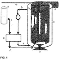
FIG. 1 is a schematic of a crystallizer according to the present invention, said crystallizer being used in and/or working according to the method of the present invention. - Before explaining the inventive embodiments in detail, it is to be understood that the present invention is not limited in its application to the details of construction and arrangement of parts illustrated in the accompanying drawings, since the present invention is capable of other embodiments and being practiced or carried out in various ways. Also, it is to be understood that the phraseology or terminology employed herein is for the purpose of description and not of limitation.
- In the description above and below, terms such as horizontal, upright, vertical, above, below, beneath and the like, are used solely for the purpose of clarity illustrating the present invention and should not be taken as words of limitation. The drawings are for the purpose of illustrating the present invention and are not intended to be to scale.
- A crystallizer is shown in
FIG. 1 as well as a schematic of the operation of the crystallizer in the method of the present invention. Produced water from an oil and gas production process is fed throughline 4 to a porous pipe G which will distribute the produced water throughout the chamber C. - Liquid nitrogen (LIN) is fed from a liquid nitrogen (LIN) source A through line 1 to a fluid temperature control system B which will cool the liquid nitrogen (LIN) and form gaseous nitrogen (GAN). Such a system may be a CUMULUS system available from Linde AG. The gaseous nitrogen (GAN) is fed from the fluid temperature control system B through
line 2 to the chamber C where it will enter a nozzle D. - The nozzle D will also be in fluid communication with the produced water present in chamber C and will direct the produced water and gaseous nitrogen (GAN) to an interior pipe F where they will form slush or ice crystals in the interior pipe F. This slush or ice crystals will be forced through the top of the interior pipe F where they can be recovered as fresh water from the chamber C through
line 6. - The gaseous nitrogen (GAN) will be recovered from the top of the chamber C where it will be fed through line 7 to the fluid temperature control system B where it can then be cooled in temperature and fed through line 8 back to the chamber C and nozzle D.
- A scraper E is mounted circumferentially around the porous pipe G. The scraper E will have arms extending outwards from its center and these arms will contact at least a portion of the height of the interior wall of the chamber C. This scraper E will be driven by an electric motor or exhaust gaseous nitrogen.
- This scraper E will be operated periodically and the arms will contact salts that have formed on the interior walls of the chamber C. These salts are the byproducts of contaminants present in the produced water and will be separated out as a result of the operation of the crystallizer.
- The salts will be removed from the bottom of the chamber C through
line 5 where they can be recovered, purified further as necessary and reused in suitable industrial operations or disposed of in an environmentally responsible manner. - It will be understood that the embodiments described herein are merely exemplary, and that one skilled in the art may make variations and modifications without departing from the spirit and scope of the present invention. All such variations and modifications are intended to be included within the scope of the present invention as described and claimed herein. Further, all embodiments disclosed are not necessarily in the alternative, as various embodiments of the present invention may be combined to provide the desired result.
-
- 1
- line or pipe or tube from liquid nitrogen (LIN) source A to fluid temperature control system B
- 2
- line or pipe or tube from fluid temperature control system B to chamber C
- 4
- line or pipe or tube for feeding or introducing produced water
- 5
- line or pipe or tube for removing salts from bottom of chamber C
- 6
- line or pipe or tube for recovering fresh water
- 7
- line or pipe or tube from chamber C to fluid temperature control system B
- 8
- line or pipe or tube from fluid temperature control system B to chamber C and to nozzle D
- A
- liquid nitrogen (LIN) source
- B
- fluid temperature control system
- C
- chamber
- D
- nozzle
- E
- scraper
- F
- interior pipe
- G
- porous pipe
Claims (15)
- A crystallizer comprising- a chamber (C) being cylindrical in shape and comprising an interior wall and a top and a bottom, the chamber (C) being in fluid communication with a pipe (4) for introducing produced water, the pipe (4) being in fluid communication with a porous pipe (G) to allow for distribution of the produced water through the interior of the chamber (C);- a source of gaseous nitrogen (GAN) in fluid communication with a nozzle (D) wherein the nozzle (D) is located inside the chamber (C) and is in fluid communication with an interior pipe (F) which is further in fluid communication with the produced water;- at least one scraper (E) which is mounted circumferentially about the porous pipe (G) and has arms that extend outwardly from the scraper (E) center in contact with the interior wall of the chamber (C) thereby scraping salt crystals on the interior wall of the chamber (C); and- a top pipe in fluid communication with the chamber (C) thereby to remove fresh water from the chamber (C).
- The crystallizer according to claim 1 wherein the gaseous nitrogen (GAN) is formed by feeding liquid nitrogen (LIN) to a fluid temperature control system (B).
- The crystallizer according to claim 2 wherein gaseous nitrogen (GAN) is recovered from the chamber (C).
- The crystallizer according to claim 3 wherein the gaseous nitrogen (GAN) is fed to the fluid temperature control system (B).
- The crystallizer according to at least one of claims 1 to 4 having salt removal means, in particular salt crystal removal means, from the bottom of the chamber (C), in particular for recovering, for being purified further and/or for being reused or disposed of.
- A method for treating produced water, comprising the steps of:a) feeding (4) produced water to a porous pipe (G) in a chamber (C) wherein the chamber (C) is cylindrically shaped having an interior wall with a top and a bottom;b) feeding gaseous nitrogen (GAN) to a nozzle (D) present in the chamber (C), wherein the nozzle (D) is in fluid communication with an interior pipe (F);c) feeding the produced water to the interior pipe (F) wherein slush is formed in the interior pipe (F) and this slush is forced through the interior pipe (F) to the top of the chamber (C);d) operating at least one scraper (E) which is mounted circumferentially about the porous pipe (G) and has arms that extend outwardly from the scraper (E) center in contact with the interior wall of the chamber (C) wherein the scraper (E) will contact and remove salt crystals from the interior walls of the chamber (C);e) recovering salts, in particular salt crystals, from the bottom of the chamber (C); andf) recovering fresh water from the chamber (C).
- The method according to claim 6 wherein the produced water is from an oil and gas production process.
- The method according to claim 6 or 7 wherein the porous pipe (G) distributes the produced water throughout the chamber (C).
- The method according to at least one of claims 6 to 8 wherein the nozzle (D) feeds the produced water and gaseous nitrogen (GAN) to the interior pipe (F).
- The method according to at least one of claims 6 to 9 wherein slush or ice crystals are formed in the interior pipe (F).
- The method according to at least one of claims 6 to 10 wherein the scraper (E) is operated periodically.
- The method according to at least one of claims 6 to 11 wherein the scraper (E) rotates between 0 degree and 180 degree.
- The method according to at least one of claims 6 to 12 wherein the scraper (E) is driven by an electric motor or through exhaust gaseous nitrogen (GAN).
- The method according to at least one of claims 6 to 13 wherein the salts are removed from the bottom of the chamber (C) for recovering, purifying further and/or reusing or disposing of.
- The method according to at least one of claims 6 to 14 wherein the fresh water is recovered from the chamber (C) through a top pipe.
Applications Claiming Priority (1)
| Application Number | Priority Date | Filing Date | Title |
|---|---|---|---|
| US15/238,320 US20180050280A1 (en) | 2016-08-16 | 2016-08-16 | Crystallizer and method for water reclamation |
Publications (1)
| Publication Number | Publication Date |
|---|---|
| EP3284525A1 true EP3284525A1 (en) | 2018-02-21 |
Family
ID=57960271
Family Applications (1)
| Application Number | Title | Priority Date | Filing Date |
|---|---|---|---|
| EP17153853.1A Withdrawn EP3284525A1 (en) | 2016-08-16 | 2017-01-30 | Crystallizer and method for treating produced water |
Country Status (3)
| Country | Link |
|---|---|
| US (1) | US20180050280A1 (en) |
| EP (1) | EP3284525A1 (en) |
| WO (1) | WO2018035085A1 (en) |
Cited By (1)
| Publication number | Priority date | Publication date | Assignee | Title |
|---|---|---|---|---|
| CN108480297A (en) * | 2018-03-12 | 2018-09-04 | 中国科学院上海硅酸盐研究所 | Historical relic removes salt well |
Families Citing this family (2)
| Publication number | Priority date | Publication date | Assignee | Title |
|---|---|---|---|---|
| CN110193335A (en) * | 2019-05-27 | 2019-09-03 | 衢州市沃德仪器有限公司 | A kind of high/low temperature reacting furnace |
| CN118370999B (en) * | 2024-06-21 | 2024-09-03 | 湖南欧德环保科技有限公司 | Evaporation equipment, intelligent reaction catalytic system and fixed metal catalytic bed |
Citations (6)
| Publication number | Priority date | Publication date | Assignee | Title |
|---|---|---|---|---|
| US2862548A (en) * | 1957-02-11 | 1958-12-02 | Oscar A Yost | Self-powered agitating evaporator |
| US3027320A (en) * | 1959-09-14 | 1962-03-27 | Phillips Petroleum Co | Removing salt from sea water |
| US3132096A (en) * | 1961-11-21 | 1964-05-05 | Socony Mobil Oil Co Inc | Continuous saline water purification |
| EP0455243A2 (en) * | 1990-05-03 | 1991-11-06 | Praxair Technology, Inc. | Draft tube, direct contact crystallizer |
| US20030209492A1 (en) * | 2002-05-08 | 2003-11-13 | Max Michael D. | Hydrate-based desalination/purification using permeable support member |
| WO2008113386A1 (en) * | 2007-03-20 | 2008-09-25 | Technische Universiteit Delft | Crystallizer with internal scraped cooled wall and method of use thereof |
Family Cites Families (7)
| Publication number | Priority date | Publication date | Assignee | Title |
|---|---|---|---|---|
| US3992900A (en) * | 1973-03-27 | 1976-11-23 | Avco Corporation | Plural stage freeze crystallization with wash-water/concentrate interface control |
| US4936114A (en) * | 1989-06-23 | 1990-06-26 | Chicago Bridge & Iron Technical Services Company | Apparatus and method of freeze concentrating aqueous waste and process streams to separate water from precipitable salts |
| US5362455A (en) * | 1990-05-03 | 1994-11-08 | Praxair Technology, Inc. | Draft tube, direct contact cryogenic crystallizer |
| DE59306742D1 (en) * | 1993-03-03 | 1997-07-17 | Ciba Geigy Ag | Device for producing crystal nuclei in melts and a crystallization system containing such a device |
| US5394706A (en) * | 1993-05-20 | 1995-03-07 | Waterworks International, Inc. | Freeze crystallization for the removal of water from a solution of dissolved solids |
| US6112675A (en) * | 1996-04-08 | 2000-09-05 | Foster Wheeler Environmental Corporation | Process and apparatus for treating process streams from a system for separating constituents from contaminated material |
| US8728325B2 (en) * | 2011-03-23 | 2014-05-20 | Conocophillips Company | Advanced oxidation of kinetic hydrate inhibitors |
-
2016
- 2016-08-16 US US15/238,320 patent/US20180050280A1/en not_active Abandoned
-
2017
- 2017-01-30 EP EP17153853.1A patent/EP3284525A1/en not_active Withdrawn
- 2017-08-15 WO PCT/US2017/046876 patent/WO2018035085A1/en not_active Ceased
Patent Citations (6)
| Publication number | Priority date | Publication date | Assignee | Title |
|---|---|---|---|---|
| US2862548A (en) * | 1957-02-11 | 1958-12-02 | Oscar A Yost | Self-powered agitating evaporator |
| US3027320A (en) * | 1959-09-14 | 1962-03-27 | Phillips Petroleum Co | Removing salt from sea water |
| US3132096A (en) * | 1961-11-21 | 1964-05-05 | Socony Mobil Oil Co Inc | Continuous saline water purification |
| EP0455243A2 (en) * | 1990-05-03 | 1991-11-06 | Praxair Technology, Inc. | Draft tube, direct contact crystallizer |
| US20030209492A1 (en) * | 2002-05-08 | 2003-11-13 | Max Michael D. | Hydrate-based desalination/purification using permeable support member |
| WO2008113386A1 (en) * | 2007-03-20 | 2008-09-25 | Technische Universiteit Delft | Crystallizer with internal scraped cooled wall and method of use thereof |
Non-Patent Citations (1)
| Title |
|---|
| ALLEN J BARDUHN: "The freezing processes for desalting saline water", PROCEEDINGS OF THE XIITH INTERNATIONAL CONGRESS OF REFRIGERATION, GRAFICAS REUNIDAS, MADRID, vol. 1, 9 August 1967 (1967-08-09), pages 1 - 19, XP008102211 * |
Cited By (2)
| Publication number | Priority date | Publication date | Assignee | Title |
|---|---|---|---|---|
| CN108480297A (en) * | 2018-03-12 | 2018-09-04 | 中国科学院上海硅酸盐研究所 | Historical relic removes salt well |
| CN108480297B (en) * | 2018-03-12 | 2020-12-11 | 中国科学院上海硅酸盐研究所 | Cultural Relic Desalination Well |
Also Published As
| Publication number | Publication date |
|---|---|
| WO2018035085A1 (en) | 2018-02-22 |
| US20180050280A1 (en) | 2018-02-22 |
Similar Documents
| Publication | Publication Date | Title |
|---|---|---|
| AU2008264872B2 (en) | Process and apparatus for concentrating dilute solution | |
| WO2018035085A1 (en) | Crystallizer and method for water reclamation | |
| US6159382A (en) | Waste acid recovery | |
| TWI607800B (en) | Process to purify a compound, apparatus to purify a coumpound | |
| US4810274A (en) | Vacuum freezing ambient pressure melting (VFAPM) process and sub-triple point vapor processing unit for use therein | |
| CN102471214B (en) | Device for crystallizing acrylic acid and method for crystallizing acrylic acid using same | |
| EP2203390B1 (en) | Process for the reduction of the concentration of salts in an aqueous stream containing them | |
| EP0078164B1 (en) | Separation of a mixture by the vacuum freezing vapor desublimation desublimate vaporization process | |
| CN103880585A (en) | Crystallization method applied to production of p-xylene | |
| CN1638844A (en) | Method and apparatus for processing a suspension | |
| US20180008903A1 (en) | Distillation processes, distillation units, and systems therefor | |
| EP1867372B1 (en) | Method for crystallization of paraxylene through adiabatic cooling | |
| US8163970B2 (en) | Method for adiabatic cooling type crystallization of organic compound and apparatus therefor | |
| EP3284524A1 (en) | Draft tube crystallizer | |
| CN104557436A (en) | Method for directly cooling, crystallizing and separating p-xylene by virtue of one-step process | |
| WO1999050177A1 (en) | Waste acid recovery | |
| CN101423204A (en) | Method and device capable of purifying phosphoric acid using fractional crystallization | |
| CN117003325B (en) | Method and device for treating dye wastewater by freeze concentration | |
| KR101374962B1 (en) | Method and system for obtaining solid reaction products from solutions | |
| KR20160053165A (en) | Apparatus and method of purification | |
| RU2345954C1 (en) | Water purifier | |
| EP1876147A1 (en) | Desalination process | |
| WO2025186403A1 (en) | A combined falling film crystallizer and evaporator | |
| RU2625110C1 (en) | Method of main water cleaning | |
| JP2010243141A (en) | Method and device of making slurry ice |
Legal Events
| Date | Code | Title | Description |
|---|---|---|---|
| PUAI | Public reference made under article 153(3) epc to a published international application that has entered the european phase |
Free format text: ORIGINAL CODE: 0009012 |
|
| STAA | Information on the status of an ep patent application or granted ep patent |
Free format text: STATUS: THE APPLICATION HAS BEEN PUBLISHED |
|
| AK | Designated contracting states |
Kind code of ref document: A1 Designated state(s): AL AT BE BG CH CY CZ DE DK EE ES FI FR GB GR HR HU IE IS IT LI LT LU LV MC MK MT NL NO PL PT RO RS SE SI SK SM TR |
|
| AX | Request for extension of the european patent |
Extension state: BA ME |
|
| STAA | Information on the status of an ep patent application or granted ep patent |
Free format text: STATUS: REQUEST FOR EXAMINATION WAS MADE |
|
| 17P | Request for examination filed |
Effective date: 20180821 |
|
| RBV | Designated contracting states (corrected) |
Designated state(s): AL AT BE BG CH CY CZ DE DK EE ES FI FR GB GR HR HU IE IS IT LI LT LU LV MC MK MT NL NO PL PT RO RS SE SI SK SM TR |
|
| RAP1 | Party data changed (applicant data changed or rights of an application transferred) |
Owner name: LINDE GMBH |
|
| STAA | Information on the status of an ep patent application or granted ep patent |
Free format text: STATUS: THE APPLICATION IS DEEMED TO BE WITHDRAWN |
|
| 18D | Application deemed to be withdrawn |
Effective date: 20210803 |