EP3284502A1 - Treatment tool for endoscope, and method for manufacturing treatment tool for endoscope - Google Patents
Treatment tool for endoscope, and method for manufacturing treatment tool for endoscope Download PDFInfo
- Publication number
- EP3284502A1 EP3284502A1 EP16779812.3A EP16779812A EP3284502A1 EP 3284502 A1 EP3284502 A1 EP 3284502A1 EP 16779812 A EP16779812 A EP 16779812A EP 3284502 A1 EP3284502 A1 EP 3284502A1
- Authority
- EP
- European Patent Office
- Prior art keywords
- lumen
- cut surface
- guide wire
- sheath
- treatment tool
- Prior art date
- Legal status (The legal status is an assumption and is not a legal conclusion. Google has not performed a legal analysis and makes no representation as to the accuracy of the status listed.)
- Withdrawn
Links
- 238000011282 treatment Methods 0.000 title claims abstract description 241
- 238000000034 method Methods 0.000 title claims description 95
- 238000004519 manufacturing process Methods 0.000 title claims description 37
- 238000003780 insertion Methods 0.000 claims abstract description 114
- 230000037431 insertion Effects 0.000 claims abstract description 114
- 238000005520 cutting process Methods 0.000 claims abstract description 83
- 239000002184 metal Substances 0.000 description 37
- 229910052751 metal Inorganic materials 0.000 description 37
- 230000002183 duodenal effect Effects 0.000 description 30
- 150000002739 metals Chemical class 0.000 description 12
- 210000000013 bile duct Anatomy 0.000 description 11
- 239000002872 contrast media Substances 0.000 description 10
- 239000012530 fluid Substances 0.000 description 10
- 230000010339 dilation Effects 0.000 description 9
- 239000007788 liquid Substances 0.000 description 7
- 239000000463 material Substances 0.000 description 6
- 238000004891 communication Methods 0.000 description 3
- 230000008602 contraction Effects 0.000 description 3
- 229920005989 resin Polymers 0.000 description 3
- 239000011347 resin Substances 0.000 description 3
- 239000004575 stone Substances 0.000 description 3
- 239000004952 Polyamide Substances 0.000 description 2
- 239000004020 conductor Substances 0.000 description 2
- 238000010586 diagram Methods 0.000 description 2
- 229920001971 elastomer Polymers 0.000 description 2
- 239000000806 elastomer Substances 0.000 description 2
- 239000011810 insulating material Substances 0.000 description 2
- 229920002647 polyamide Polymers 0.000 description 2
- 229920000139 polyethylene terephthalate Polymers 0.000 description 2
- 239000005020 polyethylene terephthalate Substances 0.000 description 2
- -1 polytetrafluoroethylene Polymers 0.000 description 2
- 229920001343 polytetrafluoroethylene Polymers 0.000 description 2
- 239000004810 polytetrafluoroethylene Substances 0.000 description 2
- 230000000717 retained effect Effects 0.000 description 2
- 239000000126 substance Substances 0.000 description 2
- 229920003002 synthetic resin Polymers 0.000 description 2
- 239000000057 synthetic resin Substances 0.000 description 2
- 230000000740 bleeding effect Effects 0.000 description 1
- 210000004204 blood vessel Anatomy 0.000 description 1
- 238000013189 cholangiography Methods 0.000 description 1
- 238000013461 design Methods 0.000 description 1
- 230000000916 dilatatory effect Effects 0.000 description 1
- 230000000694 effects Effects 0.000 description 1
- 238000010438 heat treatment Methods 0.000 description 1
- 239000004816 latex Substances 0.000 description 1
- 229920000126 latex Polymers 0.000 description 1
- 239000007769 metal material Substances 0.000 description 1
- 239000000203 mixture Substances 0.000 description 1
- 238000000465 moulding Methods 0.000 description 1
- 239000002504 physiological saline solution Substances 0.000 description 1
- 229920002635 polyurethane Polymers 0.000 description 1
- 239000004814 polyurethane Substances 0.000 description 1
- 238000012545 processing Methods 0.000 description 1
- 239000000243 solution Substances 0.000 description 1
- 238000003466 welding Methods 0.000 description 1
Images






















Classifications
-
- A—HUMAN NECESSITIES
- A61—MEDICAL OR VETERINARY SCIENCE; HYGIENE
- A61B—DIAGNOSIS; SURGERY; IDENTIFICATION
- A61B1/00—Instruments for performing medical examinations of the interior of cavities or tubes of the body by visual or photographical inspection, e.g. endoscopes; Illuminating arrangements therefor
- A61B1/00064—Constructional details of the endoscope body
- A61B1/00071—Insertion part of the endoscope body
- A61B1/0008—Insertion part of the endoscope body characterised by distal tip features
- A61B1/00098—Deflecting means for inserted tools
-
- A—HUMAN NECESSITIES
- A61—MEDICAL OR VETERINARY SCIENCE; HYGIENE
- A61B—DIAGNOSIS; SURGERY; IDENTIFICATION
- A61B1/00—Instruments for performing medical examinations of the interior of cavities or tubes of the body by visual or photographical inspection, e.g. endoscopes; Illuminating arrangements therefor
-
- A—HUMAN NECESSITIES
- A61—MEDICAL OR VETERINARY SCIENCE; HYGIENE
- A61B—DIAGNOSIS; SURGERY; IDENTIFICATION
- A61B1/00—Instruments for performing medical examinations of the interior of cavities or tubes of the body by visual or photographical inspection, e.g. endoscopes; Illuminating arrangements therefor
- A61B1/00131—Accessories for endoscopes
- A61B1/00133—Drive units for endoscopic tools inserted through or with the endoscope
-
- A—HUMAN NECESSITIES
- A61—MEDICAL OR VETERINARY SCIENCE; HYGIENE
- A61B—DIAGNOSIS; SURGERY; IDENTIFICATION
- A61B1/00—Instruments for performing medical examinations of the interior of cavities or tubes of the body by visual or photographical inspection, e.g. endoscopes; Illuminating arrangements therefor
- A61B1/00131—Accessories for endoscopes
- A61B1/00137—End pieces at either end of the endoscope, e.g. caps, seals or forceps plugs
-
- A—HUMAN NECESSITIES
- A61—MEDICAL OR VETERINARY SCIENCE; HYGIENE
- A61B—DIAGNOSIS; SURGERY; IDENTIFICATION
- A61B17/00—Surgical instruments, devices or methods
- A61B17/34—Trocars; Puncturing needles
- A61B17/3417—Details of tips or shafts, e.g. grooves, expandable, bendable; Multiple coaxial sliding cannulas, e.g. for dilating
- A61B17/3421—Cannulas
-
- A—HUMAN NECESSITIES
- A61—MEDICAL OR VETERINARY SCIENCE; HYGIENE
- A61B—DIAGNOSIS; SURGERY; IDENTIFICATION
- A61B18/00—Surgical instruments, devices or methods for transferring non-mechanical forms of energy to or from the body
- A61B18/04—Surgical instruments, devices or methods for transferring non-mechanical forms of energy to or from the body by heating
- A61B18/12—Surgical instruments, devices or methods for transferring non-mechanical forms of energy to or from the body by heating by passing a current through the tissue to be heated, e.g. high-frequency current
- A61B18/14—Probes or electrodes therefor
- A61B18/1492—Probes or electrodes therefor having a flexible, catheter-like structure, e.g. for heart ablation
-
- A—HUMAN NECESSITIES
- A61—MEDICAL OR VETERINARY SCIENCE; HYGIENE
- A61M—DEVICES FOR INTRODUCING MEDIA INTO, OR ONTO, THE BODY; DEVICES FOR TRANSDUCING BODY MEDIA OR FOR TAKING MEDIA FROM THE BODY; DEVICES FOR PRODUCING OR ENDING SLEEP OR STUPOR
- A61M25/00—Catheters; Hollow probes
-
- A—HUMAN NECESSITIES
- A61—MEDICAL OR VETERINARY SCIENCE; HYGIENE
- A61M—DEVICES FOR INTRODUCING MEDIA INTO, OR ONTO, THE BODY; DEVICES FOR TRANSDUCING BODY MEDIA OR FOR TAKING MEDIA FROM THE BODY; DEVICES FOR PRODUCING OR ENDING SLEEP OR STUPOR
- A61M25/00—Catheters; Hollow probes
- A61M25/01—Introducing, guiding, advancing, emplacing or holding catheters
-
- A—HUMAN NECESSITIES
- A61—MEDICAL OR VETERINARY SCIENCE; HYGIENE
- A61M—DEVICES FOR INTRODUCING MEDIA INTO, OR ONTO, THE BODY; DEVICES FOR TRANSDUCING BODY MEDIA OR FOR TAKING MEDIA FROM THE BODY; DEVICES FOR PRODUCING OR ENDING SLEEP OR STUPOR
- A61M25/00—Catheters; Hollow probes
- A61M25/01—Introducing, guiding, advancing, emplacing or holding catheters
- A61M25/0172—Exchanging a guidewire while keeping the catheter in place
-
- A—HUMAN NECESSITIES
- A61—MEDICAL OR VETERINARY SCIENCE; HYGIENE
- A61M—DEVICES FOR INTRODUCING MEDIA INTO, OR ONTO, THE BODY; DEVICES FOR TRANSDUCING BODY MEDIA OR FOR TAKING MEDIA FROM THE BODY; DEVICES FOR PRODUCING OR ENDING SLEEP OR STUPOR
- A61M25/00—Catheters; Hollow probes
- A61M25/01—Introducing, guiding, advancing, emplacing or holding catheters
- A61M25/09—Guide wires
-
- A—HUMAN NECESSITIES
- A61—MEDICAL OR VETERINARY SCIENCE; HYGIENE
- A61B—DIAGNOSIS; SURGERY; IDENTIFICATION
- A61B1/00—Instruments for performing medical examinations of the interior of cavities or tubes of the body by visual or photographical inspection, e.g. endoscopes; Illuminating arrangements therefor
- A61B1/00131—Accessories for endoscopes
- A61B1/00135—Oversleeves mounted on the endoscope prior to insertion
-
- A—HUMAN NECESSITIES
- A61—MEDICAL OR VETERINARY SCIENCE; HYGIENE
- A61B—DIAGNOSIS; SURGERY; IDENTIFICATION
- A61B1/00—Instruments for performing medical examinations of the interior of cavities or tubes of the body by visual or photographical inspection, e.g. endoscopes; Illuminating arrangements therefor
- A61B1/005—Flexible endoscopes
- A61B1/01—Guiding arrangements therefore
-
- A—HUMAN NECESSITIES
- A61—MEDICAL OR VETERINARY SCIENCE; HYGIENE
- A61B—DIAGNOSIS; SURGERY; IDENTIFICATION
- A61B1/00—Instruments for performing medical examinations of the interior of cavities or tubes of the body by visual or photographical inspection, e.g. endoscopes; Illuminating arrangements therefor
- A61B1/012—Instruments for performing medical examinations of the interior of cavities or tubes of the body by visual or photographical inspection, e.g. endoscopes; Illuminating arrangements therefor characterised by internal passages or accessories therefor
- A61B1/018—Instruments for performing medical examinations of the interior of cavities or tubes of the body by visual or photographical inspection, e.g. endoscopes; Illuminating arrangements therefor characterised by internal passages or accessories therefor for receiving instruments
-
- A—HUMAN NECESSITIES
- A61—MEDICAL OR VETERINARY SCIENCE; HYGIENE
- A61B—DIAGNOSIS; SURGERY; IDENTIFICATION
- A61B10/00—Instruments for taking body samples for diagnostic purposes; Other methods or instruments for diagnosis, e.g. for vaccination diagnosis, sex determination or ovulation-period determination; Throat striking implements
- A61B10/02—Instruments for taking cell samples or for biopsy
- A61B10/04—Endoscopic instruments, e.g. catheter-type instruments
-
- A—HUMAN NECESSITIES
- A61—MEDICAL OR VETERINARY SCIENCE; HYGIENE
- A61B—DIAGNOSIS; SURGERY; IDENTIFICATION
- A61B17/00—Surgical instruments, devices or methods
- A61B2017/0046—Surgical instruments, devices or methods with a releasable handle; with handle and operating part separable
- A61B2017/00469—Surgical instruments, devices or methods with a releasable handle; with handle and operating part separable for insertion of instruments, e.g. guide wire, optical fibre
-
- A—HUMAN NECESSITIES
- A61—MEDICAL OR VETERINARY SCIENCE; HYGIENE
- A61B—DIAGNOSIS; SURGERY; IDENTIFICATION
- A61B17/00—Surgical instruments, devices or methods
- A61B17/22—Implements for squeezing-off ulcers or the like on inner organs of the body; Implements for scraping-out cavities of body organs, e.g. bones; for invasive removal or destruction of calculus using mechanical vibrations; for removing obstructions in blood vessels, not otherwise provided for
- A61B2017/22038—Implements for squeezing-off ulcers or the like on inner organs of the body; Implements for scraping-out cavities of body organs, e.g. bones; for invasive removal or destruction of calculus using mechanical vibrations; for removing obstructions in blood vessels, not otherwise provided for with a guide wire
- A61B2017/22039—Implements for squeezing-off ulcers or the like on inner organs of the body; Implements for scraping-out cavities of body organs, e.g. bones; for invasive removal or destruction of calculus using mechanical vibrations; for removing obstructions in blood vessels, not otherwise provided for with a guide wire eccentric
-
- A—HUMAN NECESSITIES
- A61—MEDICAL OR VETERINARY SCIENCE; HYGIENE
- A61B—DIAGNOSIS; SURGERY; IDENTIFICATION
- A61B17/00—Surgical instruments, devices or methods
- A61B17/34—Trocars; Puncturing needles
- A61B17/3417—Details of tips or shafts, e.g. grooves, expandable, bendable; Multiple coaxial sliding cannulas, e.g. for dilating
- A61B17/3421—Cannulas
- A61B2017/3445—Cannulas used as instrument channel for multiple instruments
-
- A—HUMAN NECESSITIES
- A61—MEDICAL OR VETERINARY SCIENCE; HYGIENE
- A61B—DIAGNOSIS; SURGERY; IDENTIFICATION
- A61B18/00—Surgical instruments, devices or methods for transferring non-mechanical forms of energy to or from the body
- A61B2018/00315—Surgical instruments, devices or methods for transferring non-mechanical forms of energy to or from the body for treatment of particular body parts
- A61B2018/00482—Digestive system
- A61B2018/00494—Stomach, intestines or bowel
-
- A—HUMAN NECESSITIES
- A61—MEDICAL OR VETERINARY SCIENCE; HYGIENE
- A61B—DIAGNOSIS; SURGERY; IDENTIFICATION
- A61B18/00—Surgical instruments, devices or methods for transferring non-mechanical forms of energy to or from the body
- A61B2018/00571—Surgical instruments, devices or methods for transferring non-mechanical forms of energy to or from the body for achieving a particular surgical effect
- A61B2018/00601—Cutting
-
- A—HUMAN NECESSITIES
- A61—MEDICAL OR VETERINARY SCIENCE; HYGIENE
- A61B—DIAGNOSIS; SURGERY; IDENTIFICATION
- A61B18/00—Surgical instruments, devices or methods for transferring non-mechanical forms of energy to or from the body
- A61B2018/00982—Surgical instruments, devices or methods for transferring non-mechanical forms of energy to or from the body combined with or comprising means for visual or photographic inspections inside the body, e.g. endoscopes
-
- A—HUMAN NECESSITIES
- A61—MEDICAL OR VETERINARY SCIENCE; HYGIENE
- A61B—DIAGNOSIS; SURGERY; IDENTIFICATION
- A61B18/00—Surgical instruments, devices or methods for transferring non-mechanical forms of energy to or from the body
- A61B18/04—Surgical instruments, devices or methods for transferring non-mechanical forms of energy to or from the body by heating
- A61B18/12—Surgical instruments, devices or methods for transferring non-mechanical forms of energy to or from the body by heating by passing a current through the tissue to be heated, e.g. high-frequency current
- A61B18/14—Probes or electrodes therefor
- A61B2018/1405—Electrodes having a specific shape
- A61B2018/144—Wire
-
- A—HUMAN NECESSITIES
- A61—MEDICAL OR VETERINARY SCIENCE; HYGIENE
- A61M—DEVICES FOR INTRODUCING MEDIA INTO, OR ONTO, THE BODY; DEVICES FOR TRANSDUCING BODY MEDIA OR FOR TAKING MEDIA FROM THE BODY; DEVICES FOR PRODUCING OR ENDING SLEEP OR STUPOR
- A61M25/00—Catheters; Hollow probes
- A61M25/01—Introducing, guiding, advancing, emplacing or holding catheters
- A61M2025/018—Catheters having a lateral opening for guiding elongated means lateral to the catheter
-
- A—HUMAN NECESSITIES
- A61—MEDICAL OR VETERINARY SCIENCE; HYGIENE
- A61M—DEVICES FOR INTRODUCING MEDIA INTO, OR ONTO, THE BODY; DEVICES FOR TRANSDUCING BODY MEDIA OR FOR TAKING MEDIA FROM THE BODY; DEVICES FOR PRODUCING OR ENDING SLEEP OR STUPOR
- A61M25/00—Catheters; Hollow probes
- A61M25/01—Introducing, guiding, advancing, emplacing or holding catheters
- A61M2025/0188—Introducing, guiding, advancing, emplacing or holding catheters having slitted or breakaway lumens
Definitions
- the present invention relates to a treatment tool for an endoscope and a method for manufacturing a treatment tool for an endoscope.
- Priority is claimed on Japanese Patent Application No. 2015-083528, filed April 15, 2015 , the content of which is incorporated herein by reference.
- Various treatment tools having a treatment part at a distal end portion and having a multi-lumen sheath extending from the distal end portion and the treatment part toward a proximal end side are known as treatment tools for an endoscope.
- a treatment tool used by being inserted into a bile duct, a dilation balloon configured to dilate a duodenal papilla, and a dilation balloon with a knife in which an incision knife configured to incise the duodenal papilla is combined with the dilation balloon can be cited as examples of such a treatment tool for an endoscope.
- the treatment tool for an endoscope is inserted into a patient's body along a guide wire indwelled in the patient's body.
- a guide wire lumen for inserting the guide wire is provided in a multi-lumen sheath of the treatment tool for an endoscope.
- An insertion opening for inserting the guide wire into the guide wire lumen from a proximal end side is provided at the proximal end side (proximal side) in an insertion direction of the treatment tool for an endoscope.
- the insertion opening is provided, for example, at a distal end portion of an operation part in the treatment tool for an endoscope.
- the insertion opening communicates with an opening formed at a side of a proximal end portion of the guide wire lumen in the multi-lumen sheath.
- a slit that has a narrower width than an outer diameter of the guide wire and communicates with the guide wire lumen is formed in the multi-lumen sheath along a longitudinal direction of the guide wire lumen.
- a slit that has a wider width than the outer diameter of the guide wire extends in a longitudinal direction of the treatment tool for an endoscope and is formed at a distal end side of the insertion opening in the operation part.
- the guide wire inserted into the insertion opening at the proximal end side can be inserted along the guide wire lumen.
- an operator can allow the guide wire to pass through the respective slits formed in the operation part and the multi-lumen sheath and be taken out of the lumen from a side of the multi-lumen sheath. Because of this, it is possible to perform an operation of the guide wire even beside the patient.
- Patent Literature 1 a treatment tool having slits formed at distal end sides of a multi-lumen sheath and an operation part is described in Patent Literature 1.
- Patent Literature 1 United States Patent No. 6,879,854
- the above-described conventional treatment tool for an endoscope has a problem in that it becomes difficult to insert the guide wire as the number of lumens of a multi-lumen tube increases.
- Fig. 65 is a schematic perspective view illustrating a proximal end portion of a multi-lumen tube according to an example of a treatment tool for an endoscope of a prior art.
- Fig. 66 is a schematic perspective view illustrating a constitution in the vicinity of a guide wire insertion opening.
- Figs. 67 and 68 are explanatory views of operation of the treatment tool for an endoscope of the prior art according to the example.
- a treatment tool 201 of the prior art includes a multi-lumen sheath 212 fitted in a distal end tubular part 220a of an operation part main body 220 at a proximal end side (see Fig. 66 ).
- first lumen 212a extends in a longitudinal direction of the multi-lumen sheath 212 and are formed inside the multi-lumen sheath 212.
- the first lumen 212a is a through-hole into which a guide wire (not illustrated) is inserted.
- the second lumen 212b and the third lumen 212c are through-holes having a smaller diameter than the first lumen 212a.
- the second lumen 212b and the third lumen 212c may, for example, have a linear member inserted thereinto or a fluid circulating therethrough according to use of the treatment tool 201.
- a slit 212e extending along the longitudinal direction of the multi-lumen sheath 212 and communicating with the first lumen 212a is formed in the first lumen 212a.
- a clearance width of the slit 212e is narrower than an outer shape of the guide wire (not illustrated).
- An insertion opening 212i for the guide wire is formed at a proximal end portion of the multi-lumen sheath 212 by partially cutting a sidewall part of the first lumen 212a.
- An axially cut surface 212f and a side cut surface 212g are formed around the insertion opening 212i.
- the axially cut surface 212f is a plane formed by cutting from a proximal end surface 212k of the multi-lumen sheath 212 (see Fig. 65 ) in a longitudinal direction and passing through an approximate center of the first lumen 212a.
- the side cut surface 212g is a plane formed by cutting from an outer circumferential surface, at which the slit 212e is formed, in a direction orthogonal to the longitudinal direction of the multi-lumen sheath 212 toward a distal end portion in a cutting direction of the axially cut surface 212f.
- the proximal end portion of the multi-lumen sheath 212 is inserted into the distal end tubular part 220a of the operation part main body 220 and fixed to the operation part main body 220.
- a guide wire insertion opening 220b is formed in the distal end tubular part 220a.
- the guide wire insertion opening 220b is located at a position facing the insertion opening 212i of the multi-lumen sheath 212.
- the guide wire insertion opening 220b is a substantially rectangular opening elongated in an axial direction of the multi-lumen sheath 212 and the distal end tubular part 220a.
- a width in a short-side direction of the guide wire insertion opening 220b has a dimension almost equal to a width in a short-side direction of the insertion opening 212i.
- a slit 220c passing through to a distal end of the distal end tubular part 220a is formed at a distal end of the guide wire insertion opening 220b in a longitudinal direction.
- the slit 220c extends coaxially with the slit 212e.
- a clearance width of the slit 220c is wider than an outer diameter of the guide wire (not illustrated) and is narrower than the width in the short-side direction of the guide wire insertion opening 220b.
- a guide part 220j that has a C-shaped cross-section and is fitted over the multi-lumen sheath 212 is formed at a more distal end side than the guide wire insertion opening 220b.
- the side cut surface 212g of the multi-lumen sheath 212 is fixed at a position that is an intermediate portion of the guide part 220j in the longitudinal direction. Because of this, as illustrated in Fig. 67 , a proximal end side (the right side in the drawing) of the guide part 220j covers the insertion opening 212i further toward the proximal end side than the side cut surface 212g.
- an operator inserts the guide wire 230 into the guide wire insertion opening 220b from a side of the operation part main body 220 and inserts the guide wire 230 into the first lumen 212a covered with the guide part 220j.
- the number of lumens is small and the diameter of the first lumen 212a is large. Because of this, the side cut surface 212g has an arc shape, and a width of the side cut surface 212g in a diametric direction is smaller than an outer diameter of the guide wire 230. Because of this, only a part of the distal end portion 230a of the guide wire 230 comes into contact with the side cut surface 212g in a state of protruding inward in the diametric direction from the side cut surface 212g.
- the distal end portion 230a slides and moves on the side cut surface 212g and enters the inside of the first lumen 212a.
- the guide wire 230 is smoothly inserted therein along an inner circumferential surface of the first lumen 212a.
- the operator can insert the guide wire 230 into the first lumen 212a just by pushing the guide wire 230 further.
- a multi-lumen sheath used for a treatment tool for an endoscope is increased, or a multi-lumen sheath includes a lumen having a larger diameter than a guide wire lumen into which a guide wire is inserted.
- a treatment tool for an endoscope is a dilation balloon
- a balloon lumen through which a fluid for dilating the balloon passes is required.
- an inner diameter of the balloon lumen should be made as large as possible.
- the inner diameter of the balloon lumen is sometimes equal to or larger than an inner diameter of the guide wire lumen.
- the guide wire lumen has a small diameter, a guide wire cannot be smoothly inserted therein in some cases.
- Fig. 69 is a schematic perspective view illustrating a proximal end portion of a multi-lumen tube according to another example of a treatment tool for an endoscope of the prior art.
- Fig. 70 is a schematic perspective view illustrating a constitution in the vicinity of a guide wire insertion opening.
- Fig. 71 is a view for describing operation of the treatment tool for an endoscope of the prior art according to another example.
- Fig. 72 is a plan view viewed from a direction of Z in Fig. 71 .
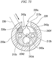
- Fig. 73 is a cross-sectional view taken along line R-R in Fig. 72 .
- a treatment tool 241 according to another example of the prior art includes a multi-lumen sheath 242 having an outer diameter equal to that of the multi-lumen sheath 212.
- points different from the treatment tool 201 will be mainly described.
- Like reference numerals will be given to members, parts, and the like identical or corresponding to those of the treatment tool 201, and overlapping descriptions will be omitted.
- the multi-lumen sheath 242 includes a first lumen 242a having a smaller diameter. Also, the multi-lumen sheath 242 includes a fourth lumen 242d having a diameter substantially equal to that of the first lumen 242a.
- the first lumen 242a and the fourth lumen 242d are arranged at positions facing each other across a central axis O242 of the multi-lumen sheath 242.
- the second lumen 212b and the third lumen 212c are also arranged at positions facing each other across the central axis O242 of the multi-lumen sheath 242.
- a direction in which the second lumen 212b and the third lumen 212c face each other is a direction orthogonal to a direction in which the first lumen 242a and the fourth lumen 242d face each other.
- the center of the first lumen 242a is disposed more outward in a diametric direction than the center of the first lumen 212a in the treatment tool 201 with respect to the center of the multi-lumen sheath 242.
- an insertion opening 242i of a guide wire is formed at a proximal end portion of the multi-lumen sheath 242 by partially cutting a sidewall part of the first lumen 242a.
- An axially cut surface 242f and a side cut surface 242g are formed around the insertion opening 242i.
- the axially cut surface 242f is a plane formed by cutting from a proximal end surface 212k of the multi-lumen sheath 242 in the longitudinal direction and passes through an approximate center of the first lumen 242a.
- the side cut surface 242g is a plane formed by cutting from an outer circumferential surface at which the slit 212e is formed in a direction orthogonal to the longitudinal direction of the multi-lumen sheath 242 toward a distal end portion in a cutting direction of the axially cut surface 242f.
- the proximal end portion of the multi-lumen sheath 242 is inserted into the distal end tubular part 220a of the operation part main body 220 and fixed to the operation part main body 220.
- an operator inserts the guide wire 230 into the guide wire insertion opening 220b from a side of the operation part main body 220 and inserts the guide wire 230 into the first lumen 242a covered with the guide part 220j.
- the operator inserts the distal end portion 230a of the guide wire 230 between the guide part 220j and the axially cut surface 242f.
- the distal end portion 230a abuts the side cut surface 242g.
- the number of lumens is larger than the multi-lumen sheath 212, and the inner diameter of the first lumen 242a is smaller than the inner diameter of the first lumen 212a. Because of this, as illustrated in Fig. 73 , a width of the side cut surface 242g in the diametric direction is wider than the width in the diametric direction of the side cut surface 212g. Because of this, for example, a portion at which the width in the diametric direction of the side cut surface 242g is equal to or larger than the outer diameter of the guide wire 230 is formed.
- the distal end portion 230a does not move inside the first lumen 242a in some cases.
- the distal end portion 230a of the guide wire 230 may be easily caught by the side cut surface 242g and be unable to advance.
- the operator needs to pull the guide wire 230 back and attempt insertion again or perform insertion while positioning the guide wire 230 so that the distal end portion 230a enters the first lumen 242a.
- the present invention has been made in view of the above-described problems, and an objective of the present invention is to provide a treatment tool for an endoscope in which, when equipped with a multi-lumen sheath, a guide wire can be easily inserted into a guide wire lumen, and a method for manufacturing the treatment tool for an endoscope.
- a treatment tool for an endoscope includes a multi-lumen sheath having a plurality of lumens including a guide wire lumen into which a guide wire is inserted, and a first slit extending along an axial direction of the guide wire lumen and through which the guide wire is configured to be taken in and out of the guide wire lumen, and a sheath-retaining part including a tubular part configured to retain a first end portion of the multi-lumen sheath and having a guide wire insertion opening formed at a side surface of the tubular part, the guide wire insertion includes a second slit overlapping the first slit when viewed from a diametric direction and having a wider clearance than the first slit and a main opening having a wider opening width than the second slit formed in that order from a distal end side, wherein the first end portion of the multi-lumen sheath has a first side cut surface and a second side cut surface formed by being intersected
- the first side cut surface and the second side cut surface may be orthogonal to the axially cut surface.
- the first side cut surface and the second side cut surface may be arranged at a position further toward the distal end side than the guide wire insertion opening when viewed from the diametric direction and overlapping the tubular part.
- a method for manufacturing a treatment tool for an endoscope is a method for manufacturing a treatment tool for an endoscope, the treatment tool including a multi-lumen sheath having a plurality of lumens including a guide wire lumen into which a guide wire is inserted and a first slit extending along an axial direction of the guide wire lumen and through which the guide wire is configured to be taken in and out of the guide wire lumen, and a sheath-retaining part including a tubular part configured to retain a first end portion of the multi-lumen sheath, and includes forming, in the first end portion of the multi-lumen sheath, a first side cut surface and a second side cut surface by forming an X-shape intersecting in an axial direction of the multi-lumen sheath and cutting the multi-lumen sheath from an outer circumferential surface of the multi-lumen sheath to an inside of the guide wire lumen, forming, in the first end
- a treatment tool for an endoscope and a method for manufacturing a treatment tool for an endoscope when a guide wire is inserted, because the guide wire moves along a first side cut surface and a second side cut surface which intersect in an X-shape even when deviating from a guide wire lumen, the guide wire can be easily inserted into the guide wire lumen when the treatment tool for an endoscope includes a multi-lumen sheath.
- a treatment tool for an endoscope according to a first embodiment of the present invention will be described.
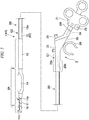
- Fig. 1 is a schematic perspective view illustrating a constitution of the treatment tool for an endoscope according to the first embodiment of the present invention.
- Fig. 2 is a schematic front view illustrating the constitution of the treatment tool for an endoscope according to the first embodiment of the present invention.
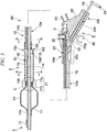
- Fig. 3 is a schematic cross-sectional view along a longitudinal direction of the treatment tool for an endoscope according to the first embodiment of the present invention.
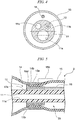
- Fig. 4 is a cross-sectional view taken along line A-A in Fig. 3 .
- Fig. 5 is an enlarged view of portion C in Fig. 3 .
- Fig. 6 is a schematic perspective view illustrating a constitution of an elongation suppressing wire of the treatment tool for an endoscope according to the first embodiment of the present invention.
- Fig. 7 is a cross-sectional view taken along line B - B in Fig. 3 .
- Fig. 8 is a schematic perspective view illustrating a constitution inside a balloon tube of the treatment tool for an endoscope according to the first embodiment of the present invention.
- Fig. 9 is a schematic perspective view illustrating a constitution in the vicinity of a guide wire insertion opening of the treatment tool for an endoscope according to the first embodiment of the present invention.
- Fig. 10 is a plan view viewed from a direction of E in Fig. 9 .
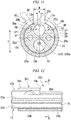
- Fig. 11 is a cross-sectional view taken along line G-G in Fig. 10 .
- Fig. 12 is a cross-sectional view taken along line F-F in Fig. 10 .
- FIG. 13 is a schematic perspective view illustrating a constitution of a second end portion of a second sheath of the treatment tool for an endoscope according to the first embodiment of the present invention.
- Fig. 14 is a plan view viewed from a direction of T in Fig. 13 .
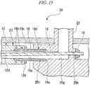
- Fig. 15 is an enlarged view of portion D in Fig. 3 .
- a treatment tool 1 (a treatment tool for an endoscope) according to the present embodiment includes an insertion part 2 inserted into a patient's body and an operation part 3 configured to perform an operation of the treatment tool 1 from outside the patient's body.
- the insertion part 2 is a long linear member.
- the insertion part 2 is inserted into the patient's body through a treatment tool channel of an endoscope.
- distal end side in an insertion direction with respect to a patient
- proximal end side which is the opposite side thereof (a side at which the operation part 3 is provided)
- proximal end side a distal end side in an insertion direction with respect to a patient
- an "axial direction,” a “circumferential direction,” and a “diametric direction” are used in some cases.
- the axial direction is a direction along an axis.
- the circumferential direction is a direction that revolves around the axis.
- the diametric direction is a direction along a line intersecting the axis on a plane orthogonal to the axis. In the diametric direction, a direction receding from the axis is referred to as outward in the diametric direction, and a direction approaching the axis is referred to as inward in the diametric direction in some cases.
- the insertion part 2 includes a distal end side insertion part 2A and a proximal end side insertion part 2B in that order from the distal end side toward the proximal end side.
- the distal end side insertion part 2A includes a treatment part 4 and a balloon part 5 in that order from the distal end side toward the proximal end side.
- a first sheath 11 is inserted into the balloon part 5.
- the first sheath 11 is a multi-lumen sheath through which three lumens, a first lumen 11a (guide wire lumen), a second lumen 11b, and a third lumen 11c, pass in the axial direction.
- the first lumen 11a is a through-hole into which a guide wire (not illustrated) configured to guide insertion of the treatment tool 1 into a patient's body is inserted.
- the guide wire can be used as a guide for guiding a distal end portion of the insertion part 2 of the treatment tool 1 to a treatment target site.
- a guide wire having a predetermined wire diameter is used in combination with the treatment tool 1 according to an inner diameter of a blood vessel or the like at the treatment target site.
- the first lumen 11a has an inner diameter that allows the guide wire to be smoothly inserted therein.
- the second lumen 11b and the third lumen 11c are through-holes used for inserting a linear member different from the above-described guide wire or circulating a liquid chemical required for treatment.
- inner diameters of the second lumen 11b and the third lumen 11c are both smaller than the inner diameter of the first lumen 11a.
- a knife wire 10 which will be described below, can be inserted into the second lumen 11b.
- liquid such as a contrast medium can circulate through the third lumen 11c.
- the type of the treatment part 4 is not particularly limited, hereinafter, a case in which the treatment part 4 includes the knife wire 10, as illustrated in Figs. 1 to 3 , will be described as an example.
- the knife wire 10 is a conductive wire member capable of incising living tissue by applying a high-frequency current to the living tissue.
- the knife wire 10 is exposed outside the first sheath 11 at the distal end side insertion part 2A.
- a distal end portion of the knife wire 10 is locked to an inside of the second lumen 11b of the first sheath 11 (see Fig. 4 ).
- the knife wire 10 is exposed outside the first sheath 11 through a first side hole 11d communicating with the second lumen (see Fig. 4 ) and reenters the second lumen 11b from a second side hole 11e provided to communicate with the second lumen 11b at a more proximal end side than the first side hole 11d.
- the knife wire 10 that entered the second lumen 11b extends further toward the proximal end side in the second lumen 11b.
- the knife wire 10 extends to the operation part 3, which will be described below, (see Fig. 3 ) through a lumen formed in the proximal end side insertion part 2B, which will be described below, and is connected to the operation part 3.
- a portion of the knife wire 10 exposed outside the first sheath 11 contributes to the incision of living tissue.
- the knife wire 10 can be used, for example, for a treatment in which a duodenal papilla is incised.
- the first sheath 11 is formed of a flexible insulating material having heat resistance so that the knife wire 10 is inserted therein.
- the first sheath 11 is formed of, for example, polytetrafluoroethylene (PTFE).
- the balloon part 5 includes a balloon 14 and a balloon tube 15 in that order from the distal end side toward the proximal end side at an outer circumferential portion at the proximal end side of the first sheath 11.
- the balloon 14 has a tubular first neck part 14a having an inner diameter fitted over the first sheath 11 at the distal end side.
- the balloon 14 has a tubular second neck part 14b slightly larger than an outer diameter of the first sheath 11 at the proximal end side.
- An intermediate portion in the longitudinal direction of the balloon 14 can be expanded to a diameter larger than inner diameters of the first neck part 14a and the second neck part 14b.
- Fig. 3 illustrates a state in which the balloon 14 is expanded.
- Figs. 1 and 2 illustrate a state in which the balloon 14 is reduced.
- the balloon tube 15 is a tubular member having an outer diameter larger than the first sheath 11 and smaller than an outer diameter of the balloon 14 when the balloon 14 is expanded.
- a cylindrical locking part 15a for locking a fixing pipe 17 is formed at a distal end side of the balloon tube 15.
- the fixing pipe 17 includes a tubular part 17a into which the first sheath 11 is inserted and a locking part 17b protruding outward in the diametric direction from a distal end portion of the tubular part 17a.
- An elongation suppressing wire 16 configured to suppress elongation of the insertion part 2 in the longitudinal direction is fixed to a proximal end portion of the tubular part 17a.
- the elongation suppressing wire 16 is formed of a metal wire having higher tensile rigidity than of the first sheath 11 and a second sheath 12, which will be described below, (see Fig. 3 ).
- a wire formed of a stainless metal material may be adopted as the elongation suppressing wire 16.
- the elongation suppressing wire 16 extends to the operation part 3 through the balloon tube 15 and a lumen formed in the second sheath 12, which will be described below.
- a method of fixing between the elongation suppressing wire 16 and the operation part 3 will be described below.
- the fixing pipe 17 is arranged such that the locking part 17b faces the distal end side.
- the first sheath 11 is inserted into the fixing pipe 17.
- the tubular part 17a of the fixing pipe 17 is fitted in the locking part 15a of the balloon tube 15.
- the locking part 17b of the fixing pipe 17 is locked to a distal end surface 15d of the locking part 15a of the balloon tube 15.
- the treatment tool 1 receives an external force from a treatment tool channel or the like of an endoscope and tension is generated in the elongation suppressing wire 16 when the treatment tool 1 is operated, the locking part 17b is pulled by the elongation suppressing wire 16 and locked to the distal end surface of the locking part 15a.
- the second neck part 14b of the balloon 14 is arranged to be fitted over the locking part 17b of the fixing pipe 17 and the locking part 15a of the balloon tube 15. Also, the second neck part 14b is fixed to be watertight at a first fixing part 15b at an outer circumferential surface of the balloon tube 15 at the proximal end side of the locking part 15a.
- the first fixing part 15b may be formed by thermally welding the second neck part 14b to the outer circumferential portion at the proximal end side about several mm from the distal end of the balloon tube 15.
- the locking part 15a is disposed further toward the distal end side than the first fixing part 15b, the locking part 15a is not deformed due to an influence of heating. Because of this, the locking part 15a retains a cylindrical shape even after the first fixing part 15b is formed.
- the balloon 14 and the balloon tube 15 constitute a tubular part connected to be watertight.
- a distal end of the tubular part is closed by the first neck part 14a fixed to the first sheath 11.
- a second fixing part 15c at a proximal end portion of the balloon tube 15 is fitted over a second end portion E2 of the second sheath 12, which will be described below, and is fixed to the second sheath 12 to be watertight.
- a clearance extending along the axial direction of the balloon part 5 is formed between the outer circumferential surface of the first sheath 11 and inner circumferential surfaces of the balloon 14 and the balloon tube 15.
- the clearance constitutes a liquid-sending space S1 which serves as a flow path of a fluid for expanding the balloon 14.
- the elongation suppressing wire 16 extends toward the proximal end side through the liquid-sending space S1.
- the balloon 14 is a compliance balloon whose expansion diameter changes according to pressure of a fluid in the balloon 14.
- a correlation between the outer diameter of the balloon 14 and internal pressure of the balloon 14 is nonlinear.
- the outer diameter of the balloon 14 has a one-to-one relationship with at least three internal pressures.
- an outer diameter value of the balloon 14 with respect to each of the three internal pressures is defined as "compliance.”
- a compliance value of the balloon 14 is attached to, for example, the operation part 3 as a display label to be recognized by the operator.
- polyamide polyamide elastomer, polyethylene terephthalate (PET) elastomer, polyurethane, or the like may be adopted.
- PET polyethylene terephthalate
- the balloon 14 of the present embodiment manufactured with the above material has a compliance set to, for example, 15 mm/3 ATM, 17 mm/4 ATM, or 18 mm/ 5 ATM.
- the notation "15 mm/3 ATM" means that the outer diameter of the balloon 14 is 15 mm when the internal pressure of the balloon 14 is 3 ATM.
- the balloon 14 may also be formed of a very flexible material such as latex although an expansion force thereof is extremely small.
- the proximal end side insertion part 2B includes the second sheath 12 (multi-lumen sheath).
- the second sheath 12 is a multi-lumen sheath through which four lumens, a first lumen 12a (guide wire lumen), a second lumen 12b, a third lumen 12c, and a fourth lumen 12d, pass in the axial direction.
- the first lumen 12a is a through-hole into which a guide wire (not illustrated) configured to guide insertion of the treatment tool 1 into a patient's body is inserted.
- the first lumen 12a has an inner diameter that allows the guide wire to be smoothly inserted therein.
- a slit 12e (first slit) having a clearance of a predetermined width w is formed in a part of the first lumen 12a.
- the width w of the clearance in the slit 12e of the second sheath 12 is narrower than an outer diameter of the guide wire inserted into the first lumen 12a.
- the slit 12e extends from the vicinity of the second fixing part 15c at a distal end side of the second sheath 12 toward an end portion at a proximal end side thereof.
- the inner diameter of the first lumen 12a is almost the same (including the case of being the same) as that of the first lumen 11a of the first sheath 11.
- the second lumen 12b and the third lumen 12c illustrated in Fig. 7 are through-holes used for inserting a linear member different from the above-described guide wire or circulating liquid chemical required for treatment.
- inner diameters of the second lumen 12b and the third lumen 12c are almost the same (including the case of being the same) as those of the second lumen 11b and the third lumen 11c of the first sheath 11.
- the inner diameters of the second lumen 12b and the third lumen 12c are both smaller than the inner diameter of the first lumen 11a.
- the knife wire 10 can be inserted into the second lumen 12b.
- liquid such as a contrast medium can circulate through the third lumen 12c.
- the fourth lumen 12d is a through-hole (balloon lumen) for forming a flow path of a fluid for expanding the balloon 14. Further, in the present embodiment, the elongation suppressing wire 16 is inserted into the fourth lumen 12d.
- an inner diameter of the fourth lumen 12d should be made as large as possible.
- the inner diameter of the fourth lumen 12d is substantially the same (includes the case of being the same) as the inner diameter of the first lumen 12a.
- the first lumen 12a and the fourth lumen 12d are arranged at positions facing each other across a central axis 012 of the second sheath 12.
- the second lumen 12b and the third lumen 12c are also arranged at positions facing each other across the central axis O12 of the second sheath 12.
- a direction in which the second lumen 12b and the third lumen 12c face each other is a direction orthogonal to a direction in which the first lumen 12a and the fourth lumen 12d face each other.
- the second fixing part 15c of the balloon tube 15 is fixed to an outer circumferential surface of the second end portion E2, which is the distal end portion of the second sheath 12, to be watertight.
- the proximal end portion of the first sheath 11 faces the second end portion E2 of the second sheath 12.
- the second sheath 12 and the first sheath 11 are connected to each other via a connecting tube 13.
- the connecting tube 13 includes a first connecting tube 13a, a second connecting tube 13b, and a third connecting tube 13c.
- the first connecting tube 13a is connected to the first lumen 11a of the first sheath 11 and the first lumen 12a of the second sheath 12 to be watertight.
- the second connecting tube 13b is connected to the second lumen 11b of the first sheath 11 and the second lumen 12b of the second sheath 12 to be watertight.
- the third connecting tube 13c is connected to the third lumen 11c of the first sheath 11 and the third lumen 12c of the second sheath 12 to be watertight.
- the first lumens 11a and 12a, the second lumens 11b and 12b, and the third lumens 11c and 12c constitute independent communication paths via the connecting tube 13. Because the communication paths do not communicate with the liquid-sending space S1, a fluid in the liquid-sending space S1 does not enter each of the communication paths.
- the first lumens 11a and 12a communicate with the outer circumferential surroundings of the second sheath 12 by the slit 12e formed in the first lumen 12a.
- the fourth lumen 12d of the second sheath 12 opens into the liquid-sending space S1 at the second end portion E2. Because of this, the fourth lumen 12d communicates with the liquid-sending space S1.
- the elongation suppressing wire 16 extending from the fourth lumen 12d into the liquid-sending space S1 extends from a first end portion E1, which is the proximal end portion of the second sheath 12, to the operation part 3, which will be described below.
- a schematic constitution of the operation part 3 will be described prior to describing a shape of the first end portion E1 of the second sheath 12.
- the operation part 3 is arranged at the proximal end portion of the insertion part 2.
- the operation part 3 is provided to operate the balloon 14 and the knife wire 10.
- the operation part 3 includes an operation part main body 20 (sheath-retaining part), a mouthpiece part 22, a fixture 26, a slider 21, and a plug 25.
- the operation part main body 20 has a distal end tubular part 20a (tubular part) at a distal end side and has a slide guide part 20f at a proximal end side.
- the mouthpiece part 22, a connector 23, and the fixture 26 are arranged at an intermediate portion between the distal end tubular part 20a and the slide guide part 20f in the operation part main body 20.
- the distal end tubular part 20a is formed in a tubular shape having a hole portion into which the proximal end portion of the insertion part 2 is inserted. As will be described below, the first end portion E1 of the second sheath 12 is fixed to the hole portion of the distal end tubular part 20a.
- the slide guide part 20f slidably retains the slider 21, which will be described below.
- a slide hole 20n extending to the hole portion of the distal end tubular part 20a is formed inside the slide guide part 20f.
- a discharge port of a pressurizer 120 configured to control an amount of expansion of the balloon 14 can be attached to the mouthpiece part 22 to be watertight. Since the pressurizer 120 is attached to the mouthpiece part 22, a fluid for expanding the balloon 14 can be introduced from the pressurizer 120 to the balloon 14.
- the connector 23 is, for example, a luer lock connector.
- the connector 23 communicates with the third lumen 12c of the second sheath 12 via a flow path (not illustrated).
- a syringe 126 which will be described below, (see Fig. 30 ) configured to supply a contrast medium can be attached to the connector 23.
- the fixture 26 is a member configured to detachably fix the operation part 3 to the pressurizer 120.
- the fixture 26 is formed at a side surface of the operation part main body 20.
- the fixture 26 is formed in a C-shape that can be locked to an outer circumference of the pressurizer 120.
- the operation part main body 20 and the fixture 26 have rigidity such that, when a force for operating the slider 21, which will be described below, and the pressurizer 120 is applied to the slider 21 and the pressurizer 120, the operation part main body 20 and the fixture 26 are not substantially deformed.
- the operation part main body 20 and the fixture 26 may be formed by integrally molding a mold as a synthetic resin or may be formed by combining molded parts of a synthetic resin.
- the fixture 26 is attachable to and detachable from the pressurizer 120 and is selectively attachable to and detachable from any one of the pressurizer 120 and an endoscope 130, which will be described below.
- the fixture 26 may be used for a purpose of fixing the treatment tool 1 to the endoscope.
- the fixture 26 In a state in which the fixture 26 is fixed to the pressurizer 120, the fixture 26 is arranged at a position at which display of the compliance of the balloon 14 and display of a pressure of the pressurizer 120 are simultaneously visible.
- the slider 21 is an operation portion configured to advance and retract the knife wire 10 in a direction of a central axis of the knife wire 10.
- the slider 21 is movably attached to the slide guide part 20f.
- the slider 21 is formed of an insulating material.
- An operation rod 24 configured to connect the slider 21 and a proximal end portion of the knife wire 10 is fixed to the slider 21.
- the operation rod 24 is slidably inserted into the slide hole 20n in the operation part main body 20.
- the knife wire 10 extending from the second sheath 12 toward the proximal end side is connected to a distal end portion of the operation rod 24. Because of this, the knife wire 10 inserted into the insertion part 2 can be advanced and retracted at the proximal end side by the operator sliding the slider 21 along the slide guide part 20f. Because of this, the operator can pull the knife wire 10, exposed outside the first sheath 11 in the distal end side insertion part 2A, into an arc shape or loosen the knife wire 10.
- the operation rod 24 is formed of a conductor and electrically connects the knife wire 10 and the plug 25, which will be described below.
- the plug 25 is a conductor fixed to the slider 21.
- the plug 25 is fixed to the proximal end portion of the knife wire 10 via the operation rod 24.
- the plug 25 and the knife wire 10 are electrically conducted via the operation rod 24.
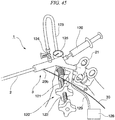
- the plug 25 can be connected to a high-frequency power supply device 128, which will be described below, (see Fig. 45 ) configured to supply high-frequency current to the knife wire 10.
- a guide wire insertion opening 20b formed in the distal end tubular part 20a is provided to insert the guide wire from the operation part 3 into the insertion part 2.
- the guide wire insertion opening 20b is not provided only for inserting the guide wire.
- the guide wire insertion opening 20b can also be used as an opening for pulling out the guide wire.
- the guide wire insertion opening 20b includes a slit 20c (second slit) and a main opening 20d.
- the slit 20c extends along the central axis O20a (see Fig. 10 ) of the distal end tubular part 20a and passes through a side surface of the distal end tubular part 20a in the diametric direction. In an extending direction, the slit 20c opens to a distal end surface of the distal end tubular part 20a and an inner circumferential portion of the main opening 20d.
- the width W of a clearance of the slit 20c is narrower than the slit 12e of the second sheath 12 and wider than an outer diameter of the guide wire 30.
- the main opening 20d is a substantially rectangular opening elongated in a direction along the central axis O20a when viewed from the diametric direction.
- a main opening distal end surface 20k which is a wall surface at a distal end side of an inner circumferential surface of the main opening 20d, is formed of a plane orthogonal to the central axis O20a.
- An opening width in a short-side direction of the main opening 20d is wider than a clearance width of the slit 20c.
- the slit 20c opens at a central part of the main opening distal end surface 20k at the distal end side (the left side in the drawing) of the main opening 20d.
- a pair of guide parts 20j protruding farther inward than the inner circumferential portion in the short-side direction of the main opening 20d are formed further toward the distal end side than the main opening 20d.
- the pair of guide parts 20j face each other in a circumferential direction of the distal end tubular part 20a.
- the slit 20c is formed by end surfaces in the circumferential direction of each of the guide parts 20j.
- each of the guide parts 20j are bent in an arc shape along a cylindrical tubular shape of the distal end tubular part 20a.
- a shape of a cross-section orthogonal to the axial direction at a more distal end side than the guide wire insertion opening 20b is a C-shape.
- An inclined portion 20e is a portion configured to guide an insertion posture of the guide wire 30 (see Fig. 11 ) so that it is easy for the guide wire 30 to be inserted from the proximal end side toward the distal end side with respect to the main opening 20d.
- the inclined portion 20e is formed at the proximal end side of the main opening 20d.
- the inclined portion 20e is inclined inward from the outer circumferential portion of the distal end tubular part 20a in a direction from the proximal end side toward the distal end side.
- the first end portion E1 of the second sheath 12 is inserted into a space defined by an inner circumferential surface 20m (see Figs. 11 and 12 ) of the distal end tubular part 20a.
- an opening OP is formed in the first end portion E1 of the second sheath 12 by cutting a side portion of the second sheath 12.
- the inner circumferential surface of the first lumen 12a is exposed to an inside of the opening OP.
- the opening OP When viewed from the diametric direction, the opening OP is surrounded by a pair of exposed surfaces Sf and exposed surfaces Sg and Sh being arranged in a substantially U-shape.
- the pair of exposed surfaces Sf extend in a longitudinal direction of the first lumen 12a from an end surface 12k in the axial direction at the proximal end side of the second sheath 12 toward the distal end side.
- the pair of exposed surfaces Sf extend parallel to each other across the exposed portion of the first lumen 12a.
- the pair of exposed surfaces Sf are formed of planes at equal distances from the central axis 012.
- the pair of exposed surfaces Sf are formed at positions passing through a substantial center (including the center) of the first lumen 12a.
- each of the exposed surfaces Sf extends substantially parallel (including parallel) to the second lumen 12b and the third lumen 12c.
- the exposed surfaces Sg and Sh When viewed from the diametric direction, as illustrated in Fig. 14 , the exposed surfaces Sg and Sh form a V-shape having a top part on the central axis 012.
- the exposed surfaces Sg and Sh are planes extending toward the exposed surfaces Sf from the outer circumferential surface of the second sheath 12 in which the slit 12e is formed.
- both of the exposed surfaces Sg and Sh are planes orthogonal to the exposed surfaces Sf.
- the exposed surfaces Sg and Sh when viewed from the diametric direction passing through the center of the slit 12e, the exposed surfaces Sg and Sh, for example, intersect at an angle of about 45° (includes 45°) with respect to the central axis 012.
- Each of the exposed surfaces Sf is formed by an axially cut surface 12f.
- the exposed surfaces Sg and Sh are formed by a first side cut surface 12g and a second side cut surface 12h.
- the axially cut surface 12f is a surface formed by passing through substantially the center of the first lumen 12a from the end surface 12k and cutting in a direction substantially parallel to the central axis 012, the second lumen 12b, an the third lumen 12c.
- the axially cut surface 12f is formed as two surfaces facing each other when the cutting is performed. However, as will be described below, the axially cut surface 12f facing the exposed surfaces Sf are removed when all of the cutting is completed.
- the first side cut surface 12g and the second side cut surface 12h are cut surfaces intersecting in an X-shape with respect to the second sheath 12 when viewed from the diametric direction, which passes through the center of the slit 12e, and reaching a position on the same plane as the axially cut surface 12f.
- the first side cut surface 12g and the second side cut surface 12h intersect in an X-shape at a point P on the central axis 012 disposed slightly further toward the proximal end side than the distal end portion of the axially cut surface 12f.
- the first side cut surface 12g and the second side cut surface 12h intersect at an angle of about 45° with respect to the central axis 012.
- the first side cut surface 12g (the second side cut surface 12h) is formed as two surfaces facing each other. However, as will be described below, the first side cut surface 12g (the second side cut surface 12h) facing the exposed surface Sg (Sh) is removed when all of the cutting is completed.
- the first side cut surface 12g (the second side cut surface 12h) forming the two surfaces facing each other is formed further toward the distal end side in the second sheath 12 than the point P.
- the axially cut surface 12f forming the two surfaces facing each other is formed in an area ranging from a position at which the axially cut surface 12f intersects the exposed surfaces Sg and Sh to a distal end portion in a cutting direction of the axially cut surface 12f.
- cutting edge of the cutter When cutting is performed by a cutter, a cutting edge of the cutter often performs movement in which movement parallel to the cutting edge and movement perpendicular to the cutting edge are combined.
- the "cutting direction" in the present specification refers to a direction orthogonal to a cutting edge among movement directions of the cutting edge when cutting is performed.
- a triangular piece-like part 12j first piece-like part having the exposed surface Sg and the axially cut surface 12f at an outer edge thereof is formed.
- a triangular piece-like part 12i second piece-like part having the exposed surface Sh and the axially cut surface 12f at an outer edge thereof is formed.
- the first end portion E1 of the second sheath 12 having the above constitution is inserted into the distal end tubular part 20a so that the slit 12e is disposed at the center of the slit 20c when viewed from the diametric direction, as illustrated in Fig. 10 .
- a position of the first end portion E1 in the axial direction is a position at which the first side cut surface 12g and the second side cut surface 12h are closer to the distal end side than the main opening distal end surface 20k (see Figs. 10 and 12 ) and at which the end surface 12k of the second sheath 12 is further toward the proximal end side than the inclined portion 20e (see Fig. 10 ).
- the second sheath 12 is fixed to the operation part main body 20 via a fixing member 19.
- the fixing member 19 is a tubular member having a distal end portion fitted in the fourth lumen 12d and a proximal end portion locked to the operation part main body 20.
- An inner diameter of a through-hole 19a passing through the fixing member 19 in the axial direction is larger than the outer diameter of the elongation suppressing wire 16.
- An engaging protrusion 19b biting into an inner circumferential surface of the fourth lumen 12d is formed at an outer circumferential surface of the distal end portion of the fixing member 19.
- the engaging protrusion 19b protrudes outward in the diametric direction from the outer circumferential surface of the fixing member 19.
- a cylindrical proximal end side tubular part 19d is formed at the proximal end portion of the fixing member 19.
- a locking part 19c configured to lock the end surface 12k at the outer circumferential side of the fourth lumen 12d in the axial direction is formed at an intermediate portion of the fixing member 19 in the axial direction.
- the locking part 19c protrudes outward in the diametric direction from the outer circumferential surface of the fixing member 19.
- the distal end portion of the fixing member 19 is inserted into the proximal end side of the fourth lumen 12d, and the fixing member 19 is connected to the second sheath 12 by being pushed until the end surface 12k comes into contact with the locking part 19c.
- An outer diameter of the fixing member 19 is a slightly larger diameter than the fourth lumen 12d. The locking part 19c and the end surface 12k are adhered to each other. Because of this, the fixing member 19 is mounted to be watertight on the fourth lumen 12d.
- a locking hole portion 20i is provided at a distal end portion of a liquid-sending duct 20g (a left end portion of the liquid-sending duct 20g in Fig. 15 ) communicating with the mouthpiece part 22.
- the proximal end side tubular part 19d of the fixing member 19 is fitted in the locking hole portion 20i to be watertight.
- An inner diameter of the locking hole portion 20i is larger than the inner diameter of the liquid-sending duct 20g. Because of this, at the proximal end side of the locking hole portion 20i, a step is formed between the locking hole portion 20i and the liquid-sending duct 20g. The step restricts movement of the fixing member 19 so that an end surface 19e of the proximal end side tubular part 19d of the fixing member 19 does not move over the step toward the proximal end side in the axial direction.
- the fourth lumen 12d communicates with the inside of the liquid-sending duct 20g and the mouthpiece part 22, a fluid can be introduced into the liquid-sending space S1 or the fluid in the liquid-sending space S1 can be discharged through the mouthpiece part 22.
- the elongation suppressing wire 16 inserted into the fourth lumen 12d extends into the liquid-sending duct 20g through the through-hole 19a of the fixing member 19.
- a through-hole 20h into which the elongation suppressing wire 16 is inserted is formed in the liquid-sending duct 20g.
- the proximal end portion of the elongation suppressing wire 16 is inserted into the through-hole 20h.
- the proximal end portion of the elongation suppressing wire 16 is fixed to a wall surface through which the through-hole 20h passes via a fixing part 18.
- the fixing part 18 fixes a position of the elongation suppressing wire 16 and seals the through-hole 20h to be watertight.
- the distal end portion of the elongation suppressing wire 16 is fixed to the fixing pipe 17, and the proximal end portion of the elongation suppressing wire 16 is fixed to the operation part main body 20. Because of this, the elongation suppressing wire 16 is arranged in parallel with the first sheath 11 and the second sheath 12 in a communicating space of the liquid-sending space S1 and the fourth lumen 12d. Because the elongation suppressing wire 16 is formed of a metal wire, tensile rigidity thereof is higher than the first sheath 11 and the second sheath 12.
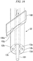
- Fig. 16 is a perspective process explanatory view of a process for manufacturing the treatment tool for an endoscope according to the first embodiment of the present invention.
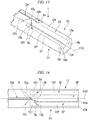
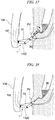
- Fig. 17 is a plan process explanatory plan view of the process for manufacturing the treatment tool for an endoscope according to the first embodiment of the present invention.
- Fig. 18 is a cross-sectional view taken along line J-J in Fig. 17 .
- Fig. 19 is a perspective process explanatory view of the process for manufacturing the treatment tool for an endoscope according to the first embodiment of the present invention.
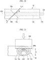
- Fig. 20 is a plan process explanatory view of the process for manufacturing the treatment tool for an endoscope according to the first embodiment of the present invention.
- Fig. 21 is a cross-sectional view taken along line K-K in Fig. 20 .
- Fig. 22 is a perspective process explanatory view of the process for manufacturing the treatment tool for an endoscope according to the first embodiment of the present invention.
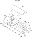
- Fig. 23 is a perspective process explanatory view of the process for manufacturing the treatment tool for an endoscope according to the first embodiment of the present invention.
- Fig. 24 is a plan view viewed from a direction of U in Fig. 23 .
- Fig. 25 is a cross-sectional view taken along line L-L in Fig. 24 .
- a multi-lumen tube 32 in which the first lumen 12a, the second lumen 12b, the third lumen 12c, and the fourth lumen 12d are formed is manufactured.
- the multi-lumen tube 32 is horizontally arranged so that the first lumen 12a is on an upper side thereof and the fourth lumen 12d is on a lower side, and a core metal 101 is inserted into the first lumen 12a.
- the core metal 101 comes into contact with the lowermost inner circumferential surface of the first lumen 12a due to its own weight.
- the core metal 101 is inserted to a position more inward than the position at which the first side cut surface 12g and the second side cut surface 12h intersect.
- the core metal 101 is a member configured to regulate a cutting amount of a cutter 100 configured to form the first side cut surface 12g and the second side cut surface 12h.
- a posture of the cutter 100 is a posture in which a cutting edge 100a is horizontally arranged and the cutting direction is along a vertical direction. Further, the posture of the cutter 100 in a plan view with respect to the multi-lumen tube 32 is inclined by an angle ⁇ with respect to a central axis O32 of the multi-lumen tube 32, as illustrated in Fig. 17 .
- the angle ⁇ is equal to an angle of inclination between the first side cut surface 12g and the central axis 012 in the second sheath 12. In the present embodiment, the angle ⁇ is about 45°.
- the cutter 100 causes a cut in a part of the multi-lumen tube 32 and forms the first side cut surface 12g.
- the cutting edge 100a of the cutter 100 comes into contact with the core metal 101, the cutting cannot be performed further. Because of this, the first side cut surface 12g stops at a position of the cutting edge 100a.
- the cutting edge 100a may be placed on a horizontal plane where a distance from the outer circumferential surface becomes h at a side opposite the first lumen 12a.
- the cutting edge 100a is at a position equally distant from the centers of the second lumen 12b and the third lumen 12c.
- the cutter 100 is rotated around a vertical axis to cut into the multi-lumen tube 32 in a posture inclined by the angle ⁇ at a side of the multi-lumen tube 32 opposite the central axis O32 (see Fig. 20 ).
- the cutter 100 cuts into a position intersecting the center of the first side cut surface 12g.
- the cutter 100 cuts until the cutting edge 100a comes into contact with the core metal 101 as described above. When the cutting edge 100a comes into contact with the core metal 101, the cutter 100 is pulled out.
- the first side cut surface 12g and the second side cut surface 12h intersecting in an X-shape at the point P when viewed from the diametric direction are formed.
- first side cut surface 12g and the second side cut surface 12h pass through an upper half of the first lumen 12a.
- the cutter 100 is arranged at an upper portion of the core metal 101 extending from the multi-lumen tube 32. Then, as illustrated in Figs. 23 and 24 , the cutter 100 performs cutting in a cutting direction which is a direction from the end surface 12k along the central axis of the multi-lumen tube 32.
- the cutting edge 100a of the cutter 100 retains a posture orthogonal to the central axis O32 of the multi-lumen tube 32 (see Fig. 23 ).
- the cutter 100 comes into contact with the core metal 101 from above and horizontally moves with the core metal 101 as a guide.
- the axially cut surface 12f is formed from the end surface 12k along the horizontal plane parallel to the central axis O32.
- An end portion of the multi-lumen tube 32 is divided into two with the axially cut surface 12f as a boundary therebetween due to the cutting operation.
- the two divided parts are connected to each other at a distal end side of the cutting edge 100a as long as the two divided parts do not intersect any of the first side cut surface 12g and the second side cut surface 12h.
- the axially cut surface 12f intersects lower end portions of the first side cut surface 12g and the second side cut surface 12h.
- a cutout portion 32B above the cutter 100 is spaced apart from a tube main body portion 32A.
- the cutout portion is further increased.
- the cutting operation is stopped to prevent this when the cutting edge 100a of the cutter 100 moves slightly further than the point P toward the distal end side when viewed from the diametric direction.
- the piece-like parts 12j and 12i are formed in a range in which the first side cut surface 12g and the second side cut surface 12h overlap the axially cut surface 12f when viewed from the diametric direction.
- the tube main body portion 32A As illustrated in Figs. 23 and 24 , when the cutout portion 32B is removed, the tube main body portion 32A, of which the side portion is cut out, remains in the multi-lumen tube 32. Since the cutout portion 32B is removed, the first side cut surface 12g and the second side cut surface 12h closer to the end surface 12k than the point P are exposed. As a result, the exposed surfaces Sg and Sh are formed in the tube main body portion 32A.
- the axially cut surface 12f between the exposed surfaces Sg and Sh and the end surface 12k is exposed, and the exposed surface Sf is formed in the tube main body portion 32A therefrom.
- the first lumen 12a is exposed in an area surrounded by the exposed surfaces Sg, Sh, and Sf arranged in a substantially U-shape when viewed from the diametric direction. As a result, the opening OP is formed in the tube main body portion 32A.
- the slit 12e is processed along the central axis O32 from the point P of the tube main body portion 32A, which is a portion at which the first side cut surface 12g and the second side cut surface 12h intersect.
- a method of processing the slit 12e is not particularly limited.
- the slit 12e may be processed using a cutter having two cutting edges spaced apart by a clearance width of the slit 12e.
- the second sheath 12 is connected to the first sheath 11 via the connecting tube 13. Also, the knife wire 10 is inserted into the second sheath 12.
- the fixing pipe 17 is inserted into the first sheath 11, and the elongation suppressing wire 16 of the fixing pipe 17 is inserted into the fourth lumen 12d of the second sheath 12.
- the balloon 14 and the balloon tube 15 are fixed to the first sheath 11 and the second sheath 12 by inserting the second end portion E2 of the first sheath 11 and the second sheath 12 into the balloon 14 and the balloon tube 15.
- the fixing member 19 is fitted to the fourth lumen 12d, and the first end portion E1 of the second sheath 12 is inserted into the distal end tubular part 20a together with the fixing member 19.
- the second sheath 12 is retained by the operation part main body 20, which is a sheath-retaining part.
- the opening OP of the second sheath 12 is aligned with the guide wire insertion opening 20b of the second sheath 12, and the elongation suppressing wire 16 extending from the fixing member 19 is fixed to the operation part main body 20.
- the knife wire 10 extending from the first lumen 12a is fixed to the operation rod 24.
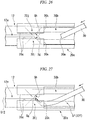
- Figs. 26 and 27 are plan explanatory views of operation of the treatment tool for an endoscope according to the first embodiment of the present invention.
- Figs. 28 and 29 are cross-sectional views for describing an action of the treatment tool for an endoscope according to the first embodiment of the present invention.
- the guide wire 30 needs to be inserted into the first lumen 12a to insert the treatment tool 1 along the guide wire 30 into a patient's body.
- the guide wire 30 can be inserted into the guide wire insertion opening 20b of the operation part 3.
- the operator inserts the distal end of the guide wire 30 into the guide wire insertion opening 20b along the inclined portion 20e (not illustrated) of the guide wire 30.
- the guide part 20j prevents the guide wire 30 from deviating outward in the diametric direction.
- a distal end 30a of the guide wire 30 comes into contact with the exposed surface Sg or the exposed surface Sh.
- Fig. 27 illustrates an example of a case in which the distal end 30a comes into contact with the exposed surface Sg.
- the exposed surface Sg has a portion wider than the outer diameter of the guide wire 30 when viewed from the axial direction, and there is a positional relationship in which most of the distal end 30a of the guide wire 30 overlap the exposed surface Sg.
- the exposed surface Sg is inclined with respect to the central axis 012 when viewed from the diametric direction. Because of this, since the distal end 30a of the guide wire 30 does not entirely come into contact with the exposed surface Sg, a large frictional force that prevents movement of the guide wire 30 does not act thereon. Further, because the exposed surface Sg is inclined at a slant with respect to an insertion direction of the guide wire 30, the distal end 30a of the guide wire 30 can smoothly move in a direction approaching the central axis 012 along the inclination of the exposed surface Sg when viewed from the diametric direction.
- the distal end 30a of the guide wire 30 moves in the direction approaching the central axis 012 when viewed from the diametric direction, the distal end 30a moves into the first lumen 12a as indicated by the two-dot chain line in Fig. 11 . As a result, the guide wire 30 is inserted into the first lumen 12a.
- the guide wire 30 has an outer diameter larger than the clearance width w of the slit 12e, when the distal end portion of the guide wire 30 enters the first lumen 12a, the guide wire 30 is inserted toward the distal end side without deviating from the inside of the first lumen 12a.
- the guide wire 30 moves along the first side cut surface 12g and the second side cut surface 12h which intersect in an X-shape. Because of this, according to the treatment tool 1, the guide wire can be easily inserted into the guide wire lumen when the treatment tool 1 includes a multi-lumen sheath.
- the piece-like parts 12j and 12i are formed.
- the first side cut surface 12g at the outer edge of the piece-like part 12i moves in a direction receding from the axially cut surface 12f continuous with the exposed surface Sf.
- An action of the piece-like part 12i is similar when the guide wire 30 is withdrawn toward the proximal end side.
- the piece-like part 12j performs exactly the same action as the piece-like part 12i.
- the piece-like parts 12i and 12j are not only deformed in the direction receding from the axially cut surface 12f continuous with the exposed surface Sf, but are also deformable by being moved in a direction along the axially cut surface 12f. Because of this, even when the piece-like parts 12i and 12j receive an external force from the guide wire 30 in the direction along the axially cut surface 12f, the reaction force acting on the guide wire 30 is reduced.
- the slit 12e is deformed when a force is applied to the guide wire 30 inserted therein. Because of this, the guide wire 30 can be retracted to the outside through the slit 12e. For example, when the guide wire 30 extending outward from the guide wire insertion opening 20b is moved toward the slit 20c, the guide wire 30 moves toward the opening of the slit 12e along the V-shaped portion formed by the exposed surfaces Sg and Sh.
- the guide wire 30 When the operator applies force to retract the guide wire 30 outward in the diametric direction and toward the distal end side, the guide wire 30 enters between the slit 12e and the slit 20c. Since the clearance width W of the slit 20c is larger than the outer diameter of the guide wire 30, the guide wire 30 does not come into contact with the slit 20c having high rigidity.
- the slit 12e has low rigidity, when the guide wire 30 is inserted therein, the clearance width thereof increases, and the guide wire 30 can be withdrawn to the outside of the first lumen 12a.
- the operator can extend the guide wire 30 to the outside of the first lumen 12a from any position at which the slit 12e is provided in the longitudinal direction of the treatment tool 1.
- the guide wire 30 extending outward from the slit 12e is returned into the first lumen 12a when pushed inward in the diametric direction by the operator.
- the guide wire 30 can be extended from the slit 12e at the distal end side of the treatment tool 1. In this case, because an operator located in the vicinity of a patient can perform the insertion of the guide wire 30 by hand, the operability of the guide wire 30 is improved.
- the operator When the operator moves the treatment tool 1 further into the body, the operator returns the guide wire 30 to the first lumen 12a by sequentially pushing the guide wire 30 back into the slit 12e.
- Figs. 30 to 52 are schematic view illustrating one process during use of the treatment tool for an endoscope according to the first embodiment of the present invention.
- the treatment tool 1 is used to perform a series of treatments including retrograde cholangiography, an incision of a duodenal papilla PV, and dilation of the duodenal papilla PV, and enable stones to be removed.
- the treatment tool 1 and the pressurizer 120 are connected to the mouthpiece part 22 via a connecting tube 123.
- the pressurizer 120 contains a dilation liquid composed of a mixture of a contrast medium and a physiological saline solution.
- the syringe 126 for injecting a contrast medium is attached to the connector 23.
- the syringe 126 for injecting a contrast medium is filled with the contrast medium.
- the syringe 126 and the connector 23 are connected to be watertight, and the contrast medium can be discharged from the distal end of the insertion part 2 through the third lumen 12c and the third lumen 11c by extruding the contrast medium from the syringe 126.
- a cylinder 121 of the pressurizer 120 has an outer circumferential portion retained by the fixture 26 of the treatment tool 1 and a fixed positional relationship with the treatment tool 1.
- both ends of the fixture 26 may be fastened by an elastic band 26A.
- the guide wire 30 configured to guide the distal end of the treatment tool 1 to a treatment target site is prepared. As illustrated in Fig. 32 , the guide wire 30 is inserted into the proximal end portion of the insertion part 2 via the guide wire insertion opening 20b of the operation part 3.
- the guide wire 30 is inserted into the first lumen 12a of the second sheath 12 (not illustrated) through the guide wire insertion opening 20b and is conveyed to an opening at the distal end side (distal end side) of the first lumen 11a of the first sheath 11.
- the insertion part 2 of the treatment tool 1 is inserted from the distal end side into a treatment tool channel 131 of the endoscope 130.
- the distal end of the insertion part 2 of the treatment tool 1 protrudes from a distal end of the treatment tool channel 131 of the endoscope 130, the distal end of the treatment tool 1 is inserted into a duodenal papilla PV by operating the endoscope 130 and operating the treatment tool 1.
- the guide wire 30 is used as a technique for inserting the distal end of the treatment tool 1 into the duodenal papilla PV in some cases.
- a tube inside the duodenal papilla PV is rarely bent in some cases.
- the guide wire 30 having a more flexible distal end portion than the insertion part 2 is used, and the guide wire 30 is first inserted from the duodenal papilla PV toward the bile duct.
- the guide wire 30 slightly protrudes from the distal end of the treatment tool 1 in a state in which the distal end of the insertion part 2 of the treatment tool 1 is placed at an entrance of the duodenal papilla PV (see Fig. 37 ).
- a direction of the flexible distal end of the guide wire 30 is oriented along a curve in the duodenal papilla PV by gently and slowly advancing or rotating the proximal end portion of the guide wire 30.
- the guide wire 30 can advance toward the bile duct over the curve of the duodenal papilla PV (see Fig. 38 ).
- the guide wire 30 configured to guide the treatment tool 1 is installed in the duodenal papilla PV before the treatment tool 1 is inserted into the duodenal papilla PV. Then, the insertion part 2 of the treatment tool 1 may be inserted deeply into the duodenal papilla PV along the guide wire 30 (see Fig. 39 ).
- the slit 12e having a width slightly smaller than the outer diameter of the guide wire 30 is formed in the second sheath 12 of the insertion part 2.
- the slit 12e is formed in the first lumen 12a (not illustrated), which is a guide wire lumen.
- the second sheath 12 Due to the second sheath 12 being formed of a resin material, the second sheath 12 can be elastically deformed.
- the second sheath 12 may withdraw the guide wire 30 to the outside even through the slit 12e by being elastically deformed. For example, a position at which the guide wire 30 is withdrawn to the outside of the second sheath 12 may be moved to a guide wire operation position Q in the vicinity of a forceps plug 173 of the endoscope 130.
- the bile duct is filled with the contrast medium from the syringe 126 attached to the operation part 3.
- the distal end portion of the knife wire 10 is moved to an incision position of the duodenal papilla PV, as illustrated in Fig. 43 .
- a connecting cord 129 of the high-frequency power supply device 128 is connected to the plug 25 of the operation part 3.
- the distal end portion of the knife wire 10 is slightly pulled into an arc shape as illustrated in Fig. 46 to come into contact with the duodenal papilla PV by the slider 21 of the operation part 3 being operated, as illustrated in Fig. 45 , and a high-frequency current is passed therethrough to incise the duodenal papilla PV.
- the insertion part 2 of the treatment tool 1 is advanced until the center of the balloon 14 almost reaches the entrance of the duodenal papilla PV in the longitudinal direction, as illustrated in Fig. 47 .
- a plunger 122 of the pressurizer 120 is advanced to dilate the balloon 14 in a state in which the balloon 14 is placed inside the duodenal papilla PV, as illustrated in Figs. 48 and 49 .
- the plunger 122 of the pressurizer 120 is retracted, as illustrated in Fig. 50 , to contract the balloon 14 in the duodenal papilla PV, as illustrated in Fig. 51 .
- the treatment tool 1 is pulled out of the treatment tool channel 131 of the endoscope 130, a stone-removing basket 140 or the like is attached to the endoscope 130, as illustrated in Fig. 52 , the basket 140 is introduced from the duodenal papilla PV to the bile duct, and the stone Ca is collected.
- Fig. 53 is a schematic view illustrating an operation of a balloon of the treatment tool for an endoscope according to the first embodiment of the present invention.
- (a-1) is a schematic perspective view illustrating a mode when an unused balloon is contracted.
- (a-2) is a schematic perspective view illustrating a mode when the balloon is dilated.
- (a-3) is a schematic perspective view illustrating a mode when the balloon is contracted after being dilated.
- Fig. 53 is a schematic view illustrating an operation of a balloon of the treatment tool for an endoscope according to the first embodiment of the present invention.
- (a-1) is a schematic perspective view illustrating a mode when an unused balloon is contracted.
- (a-2) is a schematic perspective view illustrating a mode when the balloon is dilated.
- (a-3) is a schematic perspective view illustrating a mode when the balloon is contracted after being dilated.
- Fig. 53 is a schematic view illustrating one process during use of the treatment tool for an endoscope according to the first embodiment of the present invention.
- Fig. 55 is a cross-sectional view for describing an action of the elongation suppressing wire of the treatment tool for an endoscope according to the first embodiment of the present invention.
- the elongation suppressing wire 16 is arranged in parallel with the first sheath 11, a part of the knife wire 10, and the second sheath 12 inside the insertion part 2. Because of this, when the insertion part 2 is pulled, elongation of the insertion part 2 is suppressed by the tensile rigidity of the elongation suppressing wire 16 in a range in which the elongation suppressing wire 16 is parallel thereto.
- An example of a case in which the insertion part 2 is drawn into the treatment tool channel 131 of the endoscope 130 after the balloon is contracted may be given as an example of the case in which the insertion part 2 is pulled.
- the unused balloon 14 is contracted because a dilation fluid is not supplied into the balloon 14.
- the balloon 14 is folded along the outer circumferential surface of the first sheath 11.
- the folded balloon 14 is placed in a cylindrical range having a slightly larger diameter than the first sheath 11.
- the balloon 14 is dilated when the dilation liquid is introduced into the balloon 14 by the pressurizer 120, as illustrated in (a-2) and (b-2) of Fig. 53 .
- the balloon 14 is contracted when the dilation liquid is discharged from the inside of the balloon 14 by the pressurizer 120.
- the balloon 14 is contracted as if pressed and crushed in one direction in the diametric direction, as illustrated in (a-3) and (b-3) of Fig. 53 . Because of this, a shape of the contracted balloon 14 is, for example, changed into a flat shape including a central portion 14A adhered to the outer circumferential surface of the first sheath 11 and a pair of protrusions 14B protruding outward in the diametric direction of the first sheath 11 due to the balloon 14 being adhered to itself.
- the protrusion 14B is, for example, made to be easily caught by a distal end opening 131a of the treatment tool channel 131 of the endoscope 130 when retracted the insertion part 2 from a tube inside the duodenal papilla PV, as schematically illustrated in Fig. 54 .
- the protrusion 14B is flexible, when retracted with a certain degree of force, the protrusion 14B is deformed and enters the treatment tool channel 131. However, a tensile force acts on the entire insertion part 2 until the protrusion 14B completely enters the treatment tool channel 131.
- a length of the insertion part 2 from the proximal end portion of the balloon 14 to the operation part 3 is referred to as a length L1 of the second sheath 12. It is assumed that the balloon 14 is contracted and the protrusion 14B is locked to the distal end opening 131a.
- the second sheath 12 formed of a resin material extends as illustrated in Fig. 55(b) , and a length of the insertion part 2 is extended to L1+ ⁇ L.
- the knife wire 10 inserted into the second sheath 12 cannot extend like the second sheath 12, the knife wire 10 moves toward the proximal end side by about ⁇ L.
- the knife wire 10 protruding outward from the first sheath 11 is drawn into the first sheath 11, and the first sheath 11 in the treatment part 4 is bent.
- the treatment tool 1 of the present embodiment has the elongation suppressing wire 16 inside the insertion part 2. Because of this, as illustrated in Fig. 55(c) , since the elongation suppressing wire 16 resists the tensile force even when the insertion part 2 is pulled toward the proximal end side in a state in which the balloon 14 is locked to the distal end opening 131a, elongation of the insertion part 2 hardly occurs and the length of the insertion part 2 is maintained as L1.
- Fig. 56 is a schematic perspective view illustrating a constitution of a second end portion of a second sheath of the treatment tool for an endoscope according to the second embodiment of the present invention.
- Fig. 57 is a plan view viewed from a direction of V in Fig. 56 .
- Fig. 58 is a cross-sectional view taken along line Y-Y in Fig. 57 .
- a treatment tool 41 according to the present embodiment includes a second sheath 42 (multi-lumen sheath) instead of the second sheath 12 of the treatment tool 1 according to the first embodiment.
- the second sheath 42 includes a second lumen 42b and a third lumen 42c instead of the second lumen 12b and the third lumen 12c of the second sheath 12 according to the first embodiment.
- the second lumen 42b and the third lumen 42c are in the same positional relationship as the second lumen 12b and the third lumen 12c.
- the second lumen 42b and the third lumen 42c may be arranged closer to the first lumen 12a in the direction in which the first lumen 12a and the fourth lumen 12d face each other.
- an area beside the fourth lumen 12d can be widened.
- a fifth lumen, a sixth lumen, and the like may be, for example, provided in the area beside the fourth lumen 12d.
- the second sheath 42 includes exposed surfaces sg, sh, sf, an axially cut surface 42f, a first side cut surface 42g, and a second side cut surface 42h instead of the exposed surfaces Sg, Sh, Sf, the axially cut surface 12f, the first side cut surface 12g, and the second side cut surface 12h of the second sheath 12 according to the first embodiment.
- the exposed surfaces sg and sh are the same as the exposed surfaces Sg and Sh of the first embodiment except for the fact that the exposed surfaces sg and sh are formed by the first side cut surface 42g and the second cut slit surface 42h, which will be described below.
- the exposed surface sf is formed by the axially cut surface 42f, which will be described below, the exposed surface sf is the same as the exposed surface Sf according to the first embodiment except for the fact that the exposed surface sf is formed across the second lumen 42b and the third lumen 42c.
- the axially cut surface 42f of the present embodiment is different from the axially cut surface 12f in the first embodiment in that the axially cut surface 42f intersects with any one of the first lumen 12a, the third lumen 42c, and the fourth lumen 12d.
- the axially cut surface 42f is formed as two surfaces facing each other. However, as will be described below, the axially cut surface 12f facing the exposed surface sf is removed when all of the cutting is completed.
- the first side cut surface 42g and the second side cut surface 42h are the same as the first side cut surface 12g and the second side cut surface 12h in the first embodiment in that the first side cut surface 42g and the second side cut surface 42h intersect in an X-shape at a point P on the second sheath 42 when viewed from the diametric direction passing through the center of the slit 12e, as illustrated in Fig. 57 .
- first side cut surface 42g and the second side cut surface 42h are different from the first side cut surface 12g and the second side cut surface 12h in the first embodiment in that a portion closer to the end surface 12k intersects across the axially cut surface 42f.
- the distal end portion of the first side cut surface 42g and the second side cut surface 42h in the cutting direction extends in an inclined direction that intersects the axially cut surface 42f as shown with broken lines in Fig. 58 .
- the first side cut surface 42g (the second side cut surface 42h) is formed as two surfaces facing each other. However, like the first side cut surface 12g and the second side cut surface 12h according to the first embodiment, the first side cut surface 42g (the second side cut surface 42h) facing the exposed surface sg (sh), which will be described below, is removed when all of the cutting is completed.
- the first side cut surface 42g (the second side cut surface 42h) forming two surfaces facing each other is formed further toward the distal end side in the second sheath 42 than the point P.
- the axially cut surface 42f forming two surfaces facing each other is formed in an area ranging from a position intersecting the first side cut surface 42g forming the exposed surface sg and the second side cut surface 42h forming the exposed surface sh to the distal end portion in the cutting direction of the axially cut surface 12f.
- a side portion of the second sheath 42 is cut out at the first end portion E1 of the second sheath 42, and the same opening OP as the first embodiment is formed.
- the opening OP the inner circumferential surface of the first lumen 12a is exposed outward.
- the opening OP in the present embodiment is surrounded by a pair of exposed surfaces sf consisting of two types of surfaces and the exposed surfaces sg and sh being arranged in a substantially U-shape.
- first end portion E1 of the second sheath 42 having the above constitution are inserted into the distal end tubular part 20a and fixed to the distal end tubular part 20a in same the positional relationship as the second sheath 12.
- first end portion E1 of the second sheath 42 is inserted into the distal end tubular part 20a so that the slit 12e is placed at the center of the slit 20c when viewed from the diametric direction.
- the position of the first end portion E1 in the axial direction is a position at which the first side cut surface 42g and the second side cut surface 42h are further toward the distal end side than the main opening distal end surface 20k and the end surface 12k of the second sheath 42 is further toward the proximal end side than the inclined portion 20e.
- the second lumen 42b and the third lumen 42c are open in the diametric direction in the first end portion E1.
- a tube 43 is inserted into the second lumen 42b and the third lumen 42c.
- Fig. 59 is a perspective process explanatory view of a process for manufacturing the treatment tool for an endoscope according to the second embodiment of the present invention.
- Fig. 60 is a cross-sectional process explanatory diagram of the process for manufacturing the treatment tool for an endoscope according to the second embodiment of the present invention.
- Fig. 61 is a perspective process explanatory view of the process for manufacturing the treatment tool for an endoscope according to the second embodiment of the present invention.
- Fig. 62 is a cross-sectional process explanatory view of the process for manufacturing the treatment tool for an endoscope according to the second embodiment of the present invention.
- Fig. 63 is a perspective process explanatory view of the process for manufacturing the treatment tool for an endoscope according to the second embodiment of the present invention.
- Fig. 64 is a cross-sectional process explanatory view of the process for manufacturing the treatment tool for an endoscope according to the second embodiment of the present invention.
- a multi-lumen tube 52 in which the first lumen 12a, the second lumen 42b, the third lumen 42c, and the fourth lumen 12d are formed is manufactured.
- the multi-lumen tube 52 is horizontally arranged so that the first lumen 12a is on an upper side thereof and the fourth lumen 12d is on a lower side thereof, and a core metal 102 is inserted into the first lumen 12a. Also, a core metal 103 is inserted into each of the second lumen 42b and the third lumen 42c.
- the core metal 102 comes into contact with the lowermost inner circumferential surface of the first lumen 12a due to its own weight.
- the core metals 103 come into contact with the lowermost inner circumferential surface of the second lumen 42b and the third lumen 42c due to their own weight.
- the core metal 102 and each of the core metals 103 are inserted to a position more inward than the position at which the first side cut surface 42g and the second side cut surface 42h intersect.
- the core metal 102 and each of the core metals 103 are members configured to regulate a cutting amount of the cutter 100 configured to form the first side cut surface 42g and the second side cut surface 42h.
- each of the core metals 103 is also a member configured to guide movement of the cutter 100 when forming the axially cut surface 42f.
- cutting is performed by the cutter 100 from the outer circumferential side facing the first lumen 12a and the third lumen 42c in a cutting direction toward the multi-lumen tube 52.
- a posture of the cutter 100 is different from the posture of the cutter 100 in the first embodiment in that, as illustrated in Fig. 60 , the posture is an inclined direction that allows the cutting edge 100a to simultaneously come into contact with the core metals 102 and 103 to be inserted from the outer circumferential side facing the first lumen 12a and the third lumen 42c.
- the cutter 100 causes a cut portion in the multi-lumen tube 52 and forms the first side cut surface 42g in the cut portion.
- the cutting edge 100a of the cutter 100 comes into contact with the core metals 102 and 103, the cutting cannot be performed further. Because of this, the first side cut surface 42g stops at the position of the cutting edge 100a.
- An amount by which the first lumen 12a and the third lumen 42c are cut by the cutting edge 100a may be adjusted by appropriately setting the outer diameter of the core metals 102 and 103.
- the cutter 100 is rotated around the vertical axis to cut into the multi-lumen tube 52 in a posture intersecting the first side cut surface 42g in an X-shape.
- the cutter 100 cuts until the cutting edge 100a comes into contact with the core metal 103 inserted into the second lumen 42b and the core metal 102. When the cutting edge 100a comes into contact with the core metals 102 and 103, the cutter 100 is pulled out.
- the first side cut surface 42g and the second side cut surface 42h intersecting in an X-shape at the point P when viewed from the diametric direction are formed.
- the core metal 102 is retracted from the first lumen 12a.
- the cutter 100 is placed on an upper portion of each of the core metals 103 extending from the multi-lumen tube 52.
- the cutter 100 performs cutting with a direction from the end surface 12k along the central axis of the multi-lumen tube 52 as a cutting direction.
- the cutting edge 100a of the cutter 100 retains a posture orthogonal to the central axis O32 of the multi-lumen tube 32.
- the cutter 100 is in contact with each of the core metals 103 from above and horizontally moves with each of the metal cores 103 as a guide. Due to such a cut operation of the cutter 100, the axially cut surface 42f is formed from the end surface 12k along a horizontal plane parallel to a central axis O52 of the multi-lumen tube 52 (see Fig. 64 ).
- An end portion of the multi-lumen tube 52 is divided into two with the axially cut surface 42f as a boundary therebetween by the cutting operation.
- a cutout portion (not illustrated), which is the same as the cutout portion 32B of the first embodiment, is spaced apart.
- a tube main body portion 52A is formed.
- the cutting operation is stopped when the cutting edge 100a of the cutter 100 slightly moves from the point P to the distal end side as seen from the diametric direction.
- the piece-like parts 42i and 42j are formed in a range in which the first side cut surface 42g and the second side cut surface 42h overlap the axially cut surface 42f when viewed from the diametric direction by such a cutting operation.
- the tube main body portion 52A in which a side portion is cut out is formed by forming the first side cut surface 42g, the second side cut surface 42h, and the axially cut surface 42f.
- the slit 12e is processed from the point P of the tube main body portion 52A along the central axis O52 in the same way as the first embodiment.
- the treatment tool 41 can be manufactured by performing the same assembly process as the assembly process of the second sheath 12 according to the first embodiment for the second sheath 42 except that the tube 43 is inserted into the second lumen 42b and the third lumen 42c at the first end portion E1.
- the treatment tool 41 includes the first side cut surface 42g, the second side cut surface 42h, and the axially cut surface 42f instead of the first side cut surface 12g, the second side cut surface 12h, and the axially cut surface 12f, the treatment tool 41 performs the same action as the treatment tool 1.
- the guide wire 30 even when the guide wire 30 deviates from the guide wire lumen at a time of inserting the guide wire 30, the guide wire 30 moves along the first side cut surface 42g and the second side cut surface 42h which intersect in an X-shape. Because of this, according to the treatment tool 41, the guide wire can be easily inserted into the guide wire lumen when the treatment tool 41 includes a multi-lumen sheath.
- the axially cut surface may stop further toward the proximal end side than the point P as long as the axially cut surface intersects the first side cut surface and the second side cut surface at the side of the end surface 12k.
- the slit 12e is formed after the first side cut surface, the second side cut surface, and the axially cut surface are formed has been described as an example.
- the slit 12e may be formed before any of the first side cut surface, the second side cut surface, and the axially cut surface.
- the case in which the axially cut surface is formed after the first side cut surface and the second side cut surface are formed has been described as an example.
- the first side cut surface and the second side cut surface may be formed after forming the axially cut surface.
- the axially cut surface may also be formed further toward the distal end side than the end surface 12k as long as the axially cut surface is at the side of the end surface 12k in the multi-lumen sheath. In this case, it is not necessary for the cutter forming the axially cut surface to cut into the end surface 12k.
- the present invention can be used as a treatment tool for an endoscope used together with a guide wire.
Landscapes
- Health & Medical Sciences (AREA)
- Life Sciences & Earth Sciences (AREA)
- Surgery (AREA)
- Engineering & Computer Science (AREA)
- Public Health (AREA)
- Veterinary Medicine (AREA)
- Animal Behavior & Ethology (AREA)
- General Health & Medical Sciences (AREA)
- Biomedical Technology (AREA)
- Heart & Thoracic Surgery (AREA)
- Biophysics (AREA)
- Nuclear Medicine, Radiotherapy & Molecular Imaging (AREA)
- Medical Informatics (AREA)
- Molecular Biology (AREA)
- Pathology (AREA)
- Physics & Mathematics (AREA)
- Radiology & Medical Imaging (AREA)
- Optics & Photonics (AREA)
- Pulmonology (AREA)
- Anesthesiology (AREA)
- Hematology (AREA)
- Cardiology (AREA)
- Plasma & Fusion (AREA)
- Otolaryngology (AREA)
- Endoscopes (AREA)
- Media Introduction/Drainage Providing Device (AREA)
Abstract
Description
- The present invention relates to a treatment tool for an endoscope and a method for manufacturing a treatment tool for an endoscope. Priority is claimed on Japanese Patent Application No.
2015-083528, filed April 15, 2015 - Various treatment tools having a treatment part at a distal end portion and having a multi-lumen sheath extending from the distal end portion and the treatment part toward a proximal end side are known as treatment tools for an endoscope. For example, a treatment tool used by being inserted into a bile duct, a dilation balloon configured to dilate a duodenal papilla, and a dilation balloon with a knife in which an incision knife configured to incise the duodenal papilla is combined with the dilation balloon can be cited as examples of such a treatment tool for an endoscope.
- The treatment tool for an endoscope is inserted into a patient's body along a guide wire indwelled in the patient's body. A guide wire lumen for inserting the guide wire is provided in a multi-lumen sheath of the treatment tool for an endoscope.
- An insertion opening for inserting the guide wire into the guide wire lumen from a proximal end side is provided at the proximal end side (proximal side) in an insertion direction of the treatment tool for an endoscope. The insertion opening is provided, for example, at a distal end portion of an operation part in the treatment tool for an endoscope. The insertion opening communicates with an opening formed at a side of a proximal end portion of the guide wire lumen in the multi-lumen sheath.
- To facilitate the operation of inserting the treatment tool for an endoscope into a patient's body, there is a case in which the treatment tool for an endoscope is configured so that the guide wire can be taken in and out of the guide wire lumen even at an appropriate position between a distal end portion of the treatment tool for an endoscope and the insertion opening. In this case, a slit that has a narrower width than an outer diameter of the guide wire and communicates with the guide wire lumen is formed in the multi-lumen sheath along a longitudinal direction of the guide wire lumen. Further, a slit that has a wider width than the outer diameter of the guide wire extends in a longitudinal direction of the treatment tool for an endoscope and is formed at a distal end side of the insertion opening in the operation part.
- In the treatment tool for an endoscope, the guide wire inserted into the insertion opening at the proximal end side can be inserted along the guide wire lumen. However, an operator can allow the guide wire to pass through the respective slits formed in the operation part and the multi-lumen sheath and be taken out of the lumen from a side of the multi-lumen sheath. Because of this, it is possible to perform an operation of the guide wire even beside the patient.
- For example, a treatment tool having slits formed at distal end sides of a multi-lumen sheath and an operation part is described in
Patent Literature 1. - [Patent Literature 1]
United States Patent No.6,879,854 - However, the above-described conventional treatment tool for an endoscope has a problem in that it becomes difficult to insert the guide wire as the number of lumens of a multi-lumen tube increases.
- First, a conventional treatment tool for an endoscope having a multi-lumen sheath with a small number of lumens will be described with reference to
Figs. 65 to 68 . -
Fig. 65 is a schematic perspective view illustrating a proximal end portion of a multi-lumen tube according to an example of a treatment tool for an endoscope of a prior art.Fig. 66 is a schematic perspective view illustrating a constitution in the vicinity of a guide wire insertion opening.Figs. 67 and 68 are explanatory views of operation of the treatment tool for an endoscope of the prior art according to the example. - As illustrated in
Figs. 65 and 66 , atreatment tool 201 of the prior art according to the example includes amulti-lumen sheath 212 fitted in a distal endtubular part 220a of an operation partmain body 220 at a proximal end side (seeFig. 66 ). - Three lumens, a
first lumen 212a, asecond lumen 212b, and athird lumen 212c, extend in a longitudinal direction of themulti-lumen sheath 212 and are formed inside themulti-lumen sheath 212. Thefirst lumen 212a is a through-hole into which a guide wire (not illustrated) is inserted. Thesecond lumen 212b and thethird lumen 212c are through-holes having a smaller diameter than thefirst lumen 212a. - The
second lumen 212b and thethird lumen 212c may, for example, have a linear member inserted thereinto or a fluid circulating therethrough according to use of thetreatment tool 201. - A
slit 212e extending along the longitudinal direction of themulti-lumen sheath 212 and communicating with thefirst lumen 212a is formed in thefirst lumen 212a. A clearance width of theslit 212e is narrower than an outer shape of the guide wire (not illustrated). - An insertion opening 212i for the guide wire is formed at a proximal end portion of the
multi-lumen sheath 212 by partially cutting a sidewall part of thefirst lumen 212a. An axiallycut surface 212f and aside cut surface 212g are formed around the insertion opening 212i. - The axially
cut surface 212f is a plane formed by cutting from aproximal end surface 212k of the multi-lumen sheath 212 (seeFig. 65 ) in a longitudinal direction and passing through an approximate center of thefirst lumen 212a. - The
side cut surface 212g is a plane formed by cutting from an outer circumferential surface, at which theslit 212e is formed, in a direction orthogonal to the longitudinal direction of themulti-lumen sheath 212 toward a distal end portion in a cutting direction of the axiallycut surface 212f. - As illustrated in
Fig. 66 , the proximal end portion of themulti-lumen sheath 212 is inserted into the distal endtubular part 220a of the operation partmain body 220 and fixed to the operation partmain body 220. - A guide wire insertion opening 220b is formed in the distal end
tubular part 220a. The guide wire insertion opening 220b is located at a position facing the insertion opening 212i of themulti-lumen sheath 212. - The guide wire insertion opening 220b is a substantially rectangular opening elongated in an axial direction of the
multi-lumen sheath 212 and the distal endtubular part 220a. A width in a short-side direction of the guide wire insertion opening 220b has a dimension almost equal to a width in a short-side direction of the insertion opening 212i. - A
slit 220c passing through to a distal end of the distal endtubular part 220a is formed at a distal end of the guide wire insertion opening 220b in a longitudinal direction. - At a position overlapping the
slit 212e of themulti-lumen sheath 212, theslit 220c extends coaxially with theslit 212e. A clearance width of theslit 220c is wider than an outer diameter of the guide wire (not illustrated) and is narrower than the width in the short-side direction of the guide wire insertion opening 220b. - In the distal end
tubular part 220a, aguide part 220j that has a C-shaped cross-section and is fitted over themulti-lumen sheath 212 is formed at a more distal end side than the guide wire insertion opening 220b. - The side cut
surface 212g of themulti-lumen sheath 212 is fixed at a position that is an intermediate portion of theguide part 220j in the longitudinal direction. Because of this, as illustrated inFig. 67 , a proximal end side (the right side in the drawing) of theguide part 220j covers the insertion opening 212i further toward the proximal end side than theside cut surface 212g. - The operation of inserting a
guide wire 230 from the guide wire insertion opening 220b of thetreatment tool 201 will be described with reference toFigs. 67 and 68 . - As illustrated in
Fig. 67 , an operator inserts theguide wire 230 into the guide wire insertion opening 220b from a side of the operation partmain body 220 and inserts theguide wire 230 into thefirst lumen 212a covered with theguide part 220j. - When the operator inserts a
distal end portion 230a of theguide wire 230 between theguide part 220j and the axiallycut surface 212f, as illustrated inFig. 68 , theguide wire 230 is guided by theguide part 220j. When the operator sends theguide wire 230 further toward the distal end side, thedistal end portion 230a abuts the side cutsurface 212g. - In the
multi-lumen sheath 212, the number of lumens is small and the diameter of thefirst lumen 212a is large. Because of this, theside cut surface 212g has an arc shape, and a width of theside cut surface 212g in a diametric direction is smaller than an outer diameter of theguide wire 230. Because of this, only a part of thedistal end portion 230a of theguide wire 230 comes into contact with theside cut surface 212g in a state of protruding inward in the diametric direction from theside cut surface 212g. - Because of this, when the operator continues the insertion, the
distal end portion 230a slides and moves on the side cutsurface 212g and enters the inside of thefirst lumen 212a. When thedistal end portion 230a enters thefirst lumen 212a, theguide wire 230 is smoothly inserted therein along an inner circumferential surface of thefirst lumen 212a. - As described above, even when the
guide wire 230 is inserted at a position deviating from thefirst lumen 212a of thetreatment tool 201 and is caught by theside cut surface 212g, the operator can insert theguide wire 230 into thefirst lumen 212a just by pushing theguide wire 230 further. - Nowadays, treatment tools for an endoscope are becoming multi-functional and miniaturized, and there are cases in which the number of lumens in a multi-lumen sheath used for a treatment tool for an endoscope is increased, or a multi-lumen sheath includes a lumen having a larger diameter than a guide wire lumen into which a guide wire is inserted. For example, when a treatment tool for an endoscope is a dilation balloon, a balloon lumen through which a fluid for dilating the balloon passes is required. To shorten a contraction time of a balloon, an inner diameter of the balloon lumen should be made as large as possible. In this case, the inner diameter of the balloon lumen is sometimes equal to or larger than an inner diameter of the guide wire lumen. In such a treatment tool for an endoscope, because the guide wire lumen has a small diameter, a guide wire cannot be smoothly inserted therein in some cases.
- This point will be described with reference to
Figs. 69 to 73 using another example of a conventional treatment tool for an endoscope having a multi-lumen sheath to which a large-diameter lumen is added. -
Fig. 69 is a schematic perspective view illustrating a proximal end portion of a multi-lumen tube according to another example of a treatment tool for an endoscope of the prior art.Fig. 70 is a schematic perspective view illustrating a constitution in the vicinity of a guide wire insertion opening.Fig. 71 is a view for describing operation of the treatment tool for an endoscope of the prior art according to another example.Fig. 72 is a plan view viewed from a direction of Z inFig. 71 .Fig. 73 is a cross-sectional view taken along line R-R inFig. 72 . - As illustrated in
Figs. 69 and 70 , instead of themulti-lumen sheath 212 of thetreatment tool 201, atreatment tool 241 according to another example of the prior art includes amulti-lumen sheath 242 having an outer diameter equal to that of themulti-lumen sheath 212. Hereinafter, points different from thetreatment tool 201 will be mainly described. Like reference numerals will be given to members, parts, and the like identical or corresponding to those of thetreatment tool 201, and overlapping descriptions will be omitted. - Instead of the
first lumen 212a of thetreatment tool 201, themulti-lumen sheath 242 includes afirst lumen 242a having a smaller diameter. Also, themulti-lumen sheath 242 includes afourth lumen 242d having a diameter substantially equal to that of thefirst lumen 242a. - The
first lumen 242a and thefourth lumen 242d are arranged at positions facing each other across a central axis O242 of themulti-lumen sheath 242. Thesecond lumen 212b and thethird lumen 212c are also arranged at positions facing each other across the central axis O242 of themulti-lumen sheath 242. However, a direction in which thesecond lumen 212b and thethird lumen 212c face each other is a direction orthogonal to a direction in which thefirst lumen 242a and thefourth lumen 242d face each other. - The center of the
first lumen 242a is disposed more outward in a diametric direction than the center of thefirst lumen 212a in thetreatment tool 201 with respect to the center of themulti-lumen sheath 242. - As with the
multi-lumen sheath 212, an insertion opening 242i of a guide wire is formed at a proximal end portion of themulti-lumen sheath 242 by partially cutting a sidewall part of thefirst lumen 242a. An axially cutsurface 242f and aside cut surface 242g are formed around the insertion opening 242i. - The
axially cut surface 242f is a plane formed by cutting from aproximal end surface 212k of themulti-lumen sheath 242 in the longitudinal direction and passes through an approximate center of thefirst lumen 242a. - The side cut
surface 242g is a plane formed by cutting from an outer circumferential surface at which theslit 212e is formed in a direction orthogonal to the longitudinal direction of themulti-lumen sheath 242 toward a distal end portion in a cutting direction of theaxially cut surface 242f. - As illustrated in
Fig. 70 , as with themulti-lumen sheath 212, the proximal end portion of themulti-lumen sheath 242 is inserted into the distal endtubular part 220a of the operation partmain body 220 and fixed to the operation partmain body 220. - The operation of inserting the
guide wire 230 from the guidewire insertion opening 220b of thetreatment tool 241 will be described with reference toFigs. 71 to 73 . - As in the case of the
treatment tool 201, an operator inserts theguide wire 230 into the guidewire insertion opening 220b from a side of the operation partmain body 220 and inserts theguide wire 230 into thefirst lumen 242a covered with theguide part 220j. - As illustrated in
Fig. 71 , the operator inserts thedistal end portion 230a of theguide wire 230 between theguide part 220j and theaxially cut surface 242f. When the operator sends theguide wire 230 further toward the distal end side, thedistal end portion 230a abuts the side cutsurface 242g. - In the
multi-lumen sheath 242, the number of lumens is larger than themulti-lumen sheath 212, and the inner diameter of thefirst lumen 242a is smaller than the inner diameter of thefirst lumen 212a. Because of this, as illustrated inFig. 73 , a width of the side cutsurface 242g in the diametric direction is wider than the width in the diametric direction of the side cutsurface 212g. Because of this, for example, a portion at which the width in the diametric direction of the side cutsurface 242g is equal to or larger than the outer diameter of theguide wire 230 is formed. - When the
distal end portion 230a of theguide wire 230 comes into contact with such a wide-width portion in the side cutsurface 242g, the entiredistal end portion 230a is pressed by the side cutsurface 242g. Because of this, due to a frictional force, thedistal end portion 230a is locked to the side cutsurface 242g. - As a result, even when the operator continues the insertion, the
distal end portion 230a does not move inside thefirst lumen 242a in some cases. - As described above, in the
treatment tool 241, thedistal end portion 230a of theguide wire 230 may be easily caught by the side cutsurface 242g and be unable to advance. When thedistal end portion 230a is caught by the side cutsurface 242g and cannot advance, the operator needs to pull theguide wire 230 back and attempt insertion again or perform insertion while positioning theguide wire 230 so that thedistal end portion 230a enters thefirst lumen 242a. - Because of this, workability of the operation of inserting the
guide wire 230 is deteriorated. - The present invention has been made in view of the above-described problems, and an objective of the present invention is to provide a treatment tool for an endoscope in which, when equipped with a multi-lumen sheath, a guide wire can be easily inserted into a guide wire lumen, and a method for manufacturing the treatment tool for an endoscope.
- According to a first aspect of the present invention, a treatment tool for an endoscope includes a multi-lumen sheath having a plurality of lumens including a guide wire lumen into which a guide wire is inserted, and a first slit extending along an axial direction of the guide wire lumen and through which the guide wire is configured to be taken in and out of the guide wire lumen, and a sheath-retaining part including a tubular part configured to retain a first end portion of the multi-lumen sheath and having a guide wire insertion opening formed at a side surface of the tubular part, the guide wire insertion includes a second slit overlapping the first slit when viewed from a diametric direction and having a wider clearance than the first slit and a main opening having a wider opening width than the second slit formed in that order from a distal end side, wherein the first end portion of the multi-lumen sheath has a first side cut surface and a second side cut surface formed by being intersected in an X-shape having the first slit of the multi-lumen sheath as a center when viewed from the diametric direction and cutting the multi-lumen sheath from an outer circumferential surface of the multi-lumen sheath to an inside of the guide wire lumen, an axially cut surface formed by cutting the multi-lumen sheath in parallel with a central axis of the guide wire lumen from an axial end surface side of the first end portion of the multi-lumen sheath to a position intersecting a part of the first side cut surface and a part of the second side cut surface, an opening surrounded by a portion disposed in the vicinity of the axial end surface of the first end portion in the first side cut surface, the second side cut surface, and the axially cut surface and communicating with the guide wire lumen, formed at a position overlapping the main opening, a first piece-like part having the first side cut surface and the axially cut surface at an outer edge thereof, and a second piece-like part having the second side cut surface and the axially cut surface at an outer edge thereof.
- In the treatment tool for an endoscope, the first side cut surface and the second side cut surface may be orthogonal to the axially cut surface.
- In the treatment tool for an endoscope, the first side cut surface and the second side cut surface may be arranged at a position further toward the distal end side than the guide wire insertion opening when viewed from the diametric direction and overlapping the tubular part.
- According to a second aspect of the present invention, a method for manufacturing a treatment tool for an endoscope is a method for manufacturing a treatment tool for an endoscope, the treatment tool including a multi-lumen sheath having a plurality of lumens including a guide wire lumen into which a guide wire is inserted and a first slit extending along an axial direction of the guide wire lumen and through which the guide wire is configured to be taken in and out of the guide wire lumen, and a sheath-retaining part including a tubular part configured to retain a first end portion of the multi-lumen sheath, and includes forming, in the first end portion of the multi-lumen sheath, a first side cut surface and a second side cut surface by forming an X-shape intersecting in an axial direction of the multi-lumen sheath and cutting the multi-lumen sheath from an outer circumferential surface of the multi-lumen sheath to an inside of the guide wire lumen, forming, in the first end portion of the multi-lumen sheath, an axially cut surface formed by cutting the multi-lumen sheath in parallel with a central axis of the guide wire lumen from an axial end surface side of the first end portion of the multi-lumen sheath to a position intersecting a part of the first side cut surface and a part of the second side cut surface, forming, in the first end portion of the multi-lumen sheath, an opening communicating with the guide wire lumen, a first piece-like part having the first side cut surface and the axially cut surface at an outer edge thereof, and a second piece-like part having the second side cut surface and the axially cut surface at an outer edge thereof by forming the axially cut surface, and forming, in the first end portion of the multi-lumen sheath, a first slit passing through an intersection part between the first side cut surface and the second side cut surface via the opening, extending along the axial direction of the guide wire lumen, and communicating with the guide wire lumen.
- According to a treatment tool for an endoscope and a method for manufacturing a treatment tool for an endoscope, when a guide wire is inserted, because the guide wire moves along a first side cut surface and a second side cut surface which intersect in an X-shape even when deviating from a guide wire lumen, the guide wire can be easily inserted into the guide wire lumen when the treatment tool for an endoscope includes a multi-lumen sheath.
-
-
Fig. 1 is a schematic perspective view illustrating a constitution of a treatment tool for an endoscope according to a first embodiment of the present invention. -
Fig. 2 is a schematic front view illustrating the constitution of the treatment tool for an endoscope according to the first embodiment of the present invention. -
Fig. 3 is a schematic cross-sectional view along a longitudinal direction of the treatment tool for an endoscope according to the first embodiment of the present invention. -
Fig. 4 is a cross-sectional view taken along line A-A inFig. 3 . -
Fig. 5 is an enlarged view of portion C inFig. 3 . -
Fig. 6 is a schematic perspective view illustrating a constitution of an elongation suppressing wire of the treatment tool for an endoscope according to the first embodiment of the present invention. -
Fig. 7 is a cross-sectional view taken along line B - B inFig. 3 . -
Fig. 8 is a schematic perspective view illustrating a constitution inside a balloon tube of the treatment tool for an endoscope according to the first embodiment of the present invention. -
Fig. 9 is a schematic perspective view illustrating a constitution in the vicinity of a guide wire insertion opening of the treatment tool for an endoscope according to the first embodiment of the present invention. -
Fig. 10 is a plan view viewed from a direction of E inFig. 9 . -
Fig. 11 is a cross-sectional view taken along line G-G inFig. 10 . -
Fig. 12 is a cross-sectional view taken along line F-F inFig. 10 . -
Fig. 13 is a schematic perspective view illustrating a constitution of a second end portion of a second sheath of the treatment tool for an endoscope according to the first embodiment of the present invention. -
Fig. 14 is a plan view viewed from a direction of T inFig. 13 . -
Fig. 15 is an enlarged view of portion D inFig. 3 . -
Fig. 16 is a perspective process explanatory view of a process for manufacturing the treatment tool for an endoscope according to the first embodiment of the present invention. -
Fig. 17 is a plan process explanatory plan view of the process for manufacturing the treatment tool for an endoscope according to the first embodiment of the present invention. -
Fig. 18 is a cross-sectional view taken along line J-J inFig. 17 . -
Fig. 19 is a perspective process explanatory view of the process for manufacturing the treatment tool for an endoscope according to the first embodiment of the present invention. -
Fig. 20 is a plan process explanatory view of the process for manufacturing the treatment tool for an endoscope according to the first embodiment of the present invention. -
Fig. 21 is a cross-sectional view taken along line K-K inFig. 20 . -
Fig. 22 is a perspective process explanatory view of the process for manufacturing the treatment tool for an endoscope according to the first embodiment of the present invention. -
Fig. 23 is a perspective process explanatory view of the process for manufacturing the treatment tool for an endoscope according to the first embodiment of the present invention. -
Fig. 24 is a plan view viewed from a direction of U inFig. 23 . -
Fig. 25 is a cross-sectional view taken along line L-L inFig. 24 . -
Fig. 26 is a plan explanatory view of operation of the treatment tool for an endoscope according to the first embodiment of the present invention. -
Fig. 27 is a plan explanatory view of operation of the treatment tool for an endoscope according to the first embodiment of the present invention. -
Fig. 28 is a cross-sectional view for describing an action of the treatment tool for an endoscope according to the first embodiment of the present invention. -
Fig. 29 is a cross-sectional view for describing the action of the treatment tool for an endoscope according to the first embodiment of the present invention. -
Fig. 30 is a schematic view illustrating one process during use of the treatment tool for an endoscope according to the first embodiment of the present invention. -
Fig. 31 is a schematic view illustrating one process during use of the treatment tool for an endoscope. -
Fig. 32 is a schematic view illustrating one process during use of the treatment tool for an endoscope. -
Fig. 33 is a schematic view illustrating one process during use of the treatment tool for an endoscope. -
Fig. 34 is a schematic view illustrating one process during use of the treatment tool for an endoscope. -
Fig. 35 is a schematic view illustrating one process during use of the treatment tool for an endoscope. -
Fig. 36 is a schematic view illustrating one process during use of the treatment tool for an endoscope. -
Fig. 37 is a schematic view illustrating one process during use of the treatment tool for an endoscope. -
Fig. 38 is a schematic view illustrating one process during use of the treatment tool for an endoscope. -
Fig. 39 is a schematic view illustrating one process during use of the treatment tool for an endoscope. -
Fig. 40 is a schematic view illustrating one process during use of the treatment tool for an endoscope. -
Fig. 41 is a schematic view illustrating one process during use of the treatment tool for an endoscope. -
Fig. 42 is a schematic view illustrating one process during use of the treatment tool for an endoscope. -
Fig. 43 is a schematic view illustrating one process during use of the treatment tool for an endoscope. -
Fig. 44 is a schematic view illustrating one process during use of the treatment tool for an endoscope. -
Fig. 45 is a schematic view illustrating one process during use of the treatment tool for an endoscope. -
Fig. 46 is a schematic view illustrating one process during use of the treatment tool for an endoscope. -
Fig. 47 is a schematic view illustrating one process during use of the treatment tool for an endoscope. -
Fig. 48 is a schematic view illustrating one process during use of the treatment tool for an endoscope. -
Fig. 49 is a schematic view illustrating one process during use of the treatment tool for an endoscope. -
Fig. 50 is a schematic view illustrating one process during use of the treatment tool for an endoscope. -
Fig. 51 is a schematic view illustrating one process during use of the treatment tool for an endoscope. -
Fig. 52 is a schematic view illustrating one process during use of the treatment tool for an endoscope. -
Fig. 53 is a schematic view illustrating an operation of a balloon of the treatment tool for an endoscope according to the first embodiment of the present invention. -
Fig. 54 is a schematic view illustrating one process during use of the treatment tool for an endoscope according to the first embodiment of the present invention. -
Fig. 55 is a cross-sectional view for describing an action of the elongation suppressing wire of the treatment tool for an endoscope according to the first embodiment of the present invention. -
Fig. 56 is a schematic perspective view illustrating a constitution of a second end portion of a second sheath of a treatment tool for an endoscope according to a second embodiment of the present invention. -
Fig. 57 is a plan view viewed from a direction of V inFig. 56 . -
Fig. 58 is a cross-sectional view taken along line Y-Y inFig. 57 . -
Fig. 59 is a perspective process explanatory view of a process for manufacturing the treatment tool for an endoscope according to the second embodiment of the present invention. -
Fig. 60 is a cross-sectional process explanatory diagram of the process for manufacturing the treatment tool for an endoscope according to the second embodiment of the present invention. -
Fig. 61 is a perspective process explanatory view of the process for manufacturing the treatment tool for an endoscope according to the second embodiment of the present invention. -
Fig. 62 is a cross-sectional process explanatory view of the process for manufacturing the treatment tool for an endoscope according to the second embodiment of the present invention. -
Fig. 63 is a perspective process explanatory view of the process for manufacturing the treatment tool for an endoscope according to the second embodiment of the present invention. -
Fig. 64 is a cross-sectional process explanatory view of the process for manufacturing the treatment tool for an endoscope according to the second embodiment of the present invention. -
Fig. 65 is a schematic perspective view illustrating a proximal end portion of a multi-lumen tube according to an example of a treatment tool for an endoscope of a prior art. -
Fig. 66 is a schematic perspective view illustrating a constitution in the vicinity of a guide wire insertion opening according to the example of the treatment tool for an endoscope of the prior art. -
Fig. 67 is an explanatory view of operation of the treatment tool for an endoscope of the prior art according to the example. -
Fig. 68 is an explanatory view of operation of the treatment tool for an endoscope of the prior art according to the example. -
Fig. 69 is a schematic perspective view illustrating a proximal end portion of a multi-lumen tube according to another example of a treatment tool for an endoscope of the prior art. -
Fig. 70 is a schematic perspective view illustrating a constitution in the vicinity of a guide wire insertion opening according to another example of the treatment tool for an endoscope of the prior art. -
Fig. 71 is an explanatory view of operation of the treatment tool for an endoscope of the prior art according to another example. -
Fig. 72 is a plan view viewed from a direction of Z inFig. 71 . -
Fig. 73 is a cross-sectional view taken along line R-R inFig. 72 . - Hereinafter, embodiments of the present invention will be described with reference to the accompanying drawings. In all of the drawings, like reference numerals are given to like or corresponding members, and overlapping descriptions are omitted even when embodiments are different.
- A treatment tool for an endoscope according to a first embodiment of the present invention will be described.
-
Fig. 1 is a schematic perspective view illustrating a constitution of the treatment tool for an endoscope according to the first embodiment of the present invention.Fig. 2 is a schematic front view illustrating the constitution of the treatment tool for an endoscope according to the first embodiment of the present invention.Fig. 3 is a schematic cross-sectional view along a longitudinal direction of the treatment tool for an endoscope according to the first embodiment of the present invention.Fig. 4 is a cross-sectional view taken along line A-A inFig. 3 .Fig. 5 is an enlarged view of portion C inFig. 3 .Fig. 6 is a schematic perspective view illustrating a constitution of an elongation suppressing wire of the treatment tool for an endoscope according to the first embodiment of the present invention.Fig. 7 is a cross-sectional view taken along line B - B inFig. 3 .Fig. 8 is a schematic perspective view illustrating a constitution inside a balloon tube of the treatment tool for an endoscope according to the first embodiment of the present invention.Fig. 9 is a schematic perspective view illustrating a constitution in the vicinity of a guide wire insertion opening of the treatment tool for an endoscope according to the first embodiment of the present invention.Fig. 10 is a plan view viewed from a direction of E inFig. 9 .Fig. 11 is a cross-sectional view taken along line G-G inFig. 10 .Fig. 12 is a cross-sectional view taken along line F-F inFig. 10 .Fig. 13 is a schematic perspective view illustrating a constitution of a second end portion of a second sheath of the treatment tool for an endoscope according to the first embodiment of the present invention.Fig. 14 is a plan view viewed from a direction of T inFig. 13 .Fig. 15 is an enlarged view of portion D inFig. 3 . - Because each of the drawings is a schematic view, shapes or dimensions are exaggerated therein (the same applies to the drawings below).
- As illustrated in
Figs. 1 to 3 , a treatment tool 1 (a treatment tool for an endoscope) according to the present embodiment includes aninsertion part 2 inserted into a patient's body and anoperation part 3 configured to perform an operation of thetreatment tool 1 from outside the patient's body. - The
insertion part 2 is a long linear member. Theinsertion part 2 is inserted into the patient's body through a treatment tool channel of an endoscope. - In the present specification, when describing relative positions in the
treatment tool 1, a distal end side (distal side) in an insertion direction with respect to a patient is simply referred to as a "distal end side," and a proximal end side (proximal side), which is the opposite side thereof (a side at which theoperation part 3 is provided), is simply referred to as a "proximal end side" unless indicated otherwise. - In the present specification, when describing relative positions related to an axial or tubular member (including a part) that can specify an axis such as a central axis, an "axial direction," a "circumferential direction," and a "diametric direction" are used in some cases. The axial direction is a direction along an axis. The circumferential direction is a direction that revolves around the axis. The diametric direction is a direction along a line intersecting the axis on a plane orthogonal to the axis. In the diametric direction, a direction receding from the axis is referred to as outward in the diametric direction, and a direction approaching the axis is referred to as inward in the diametric direction in some cases.
- The
insertion part 2 includes a distal endside insertion part 2A and a proximal endside insertion part 2B in that order from the distal end side toward the proximal end side. - The distal end
side insertion part 2A includes atreatment part 4 and aballoon part 5 in that order from the distal end side toward the proximal end side. Afirst sheath 11 is inserted into theballoon part 5. - As illustrated in
Fig. 4 , thefirst sheath 11 is a multi-lumen sheath through which three lumens, afirst lumen 11a (guide wire lumen), asecond lumen 11b, and athird lumen 11c, pass in the axial direction. - The
first lumen 11a is a through-hole into which a guide wire (not illustrated) configured to guide insertion of thetreatment tool 1 into a patient's body is inserted. The guide wire can be used as a guide for guiding a distal end portion of theinsertion part 2 of thetreatment tool 1 to a treatment target site. A guide wire having a predetermined wire diameter is used in combination with thetreatment tool 1 according to an inner diameter of a blood vessel or the like at the treatment target site. - The
first lumen 11a has an inner diameter that allows the guide wire to be smoothly inserted therein. - The
second lumen 11b and thethird lumen 11c are through-holes used for inserting a linear member different from the above-described guide wire or circulating a liquid chemical required for treatment. In the present embodiment, inner diameters of thesecond lumen 11b and thethird lumen 11c are both smaller than the inner diameter of thefirst lumen 11a. - For example, a
knife wire 10, which will be described below, can be inserted into thesecond lumen 11b. For example, liquid such as a contrast medium can circulate through thethird lumen 11c. - Although the type of the
treatment part 4 is not particularly limited, hereinafter, a case in which thetreatment part 4 includes theknife wire 10, as illustrated inFigs. 1 to 3 , will be described as an example. - The
knife wire 10 is a conductive wire member capable of incising living tissue by applying a high-frequency current to the living tissue. - The
knife wire 10 is exposed outside thefirst sheath 11 at the distal endside insertion part 2A. - Although not illustrated, a distal end portion of the
knife wire 10 is locked to an inside of thesecond lumen 11b of the first sheath 11 (seeFig. 4 ). - As illustrated in
Fig. 2 , theknife wire 10 is exposed outside thefirst sheath 11 through afirst side hole 11d communicating with the second lumen (seeFig. 4 ) and reenters thesecond lumen 11b from asecond side hole 11e provided to communicate with thesecond lumen 11b at a more proximal end side than thefirst side hole 11d. Theknife wire 10 that entered thesecond lumen 11b (seeFig. 4 ) extends further toward the proximal end side in thesecond lumen 11b. Further, theknife wire 10 extends to theoperation part 3, which will be described below, (seeFig. 3 ) through a lumen formed in the proximal endside insertion part 2B, which will be described below, and is connected to theoperation part 3. - A portion of the
knife wire 10 exposed outside thefirst sheath 11 contributes to the incision of living tissue. In the present embodiment, theknife wire 10 can be used, for example, for a treatment in which a duodenal papilla is incised. - In the present embodiment, the
first sheath 11 is formed of a flexible insulating material having heat resistance so that theknife wire 10 is inserted therein. In the present embodiment, thefirst sheath 11 is formed of, for example, polytetrafluoroethylene (PTFE). - As illustrated in
Fig. 1 , theballoon part 5 includes aballoon 14 and aballoon tube 15 in that order from the distal end side toward the proximal end side at an outer circumferential portion at the proximal end side of thefirst sheath 11. - As illustrated in
Fig. 3 , theballoon 14 has a tubularfirst neck part 14a having an inner diameter fitted over thefirst sheath 11 at the distal end side. Theballoon 14 has a tubularsecond neck part 14b slightly larger than an outer diameter of thefirst sheath 11 at the proximal end side. An intermediate portion in the longitudinal direction of theballoon 14 can be expanded to a diameter larger than inner diameters of thefirst neck part 14a and thesecond neck part 14b. -
Fig. 3 illustrates a state in which theballoon 14 is expanded.Figs. 1 and2 illustrate a state in which theballoon 14 is reduced. - The
balloon tube 15 is a tubular member having an outer diameter larger than thefirst sheath 11 and smaller than an outer diameter of theballoon 14 when theballoon 14 is expanded. - As illustrated in
Fig. 5 , acylindrical locking part 15a for locking a fixingpipe 17 is formed at a distal end side of theballoon tube 15. - As illustrated in
Figs. 5 and6 , the fixingpipe 17 includes atubular part 17a into which thefirst sheath 11 is inserted and a lockingpart 17b protruding outward in the diametric direction from a distal end portion of thetubular part 17a. - An
elongation suppressing wire 16 configured to suppress elongation of theinsertion part 2 in the longitudinal direction is fixed to a proximal end portion of thetubular part 17a. Theelongation suppressing wire 16 is formed of a metal wire having higher tensile rigidity than of thefirst sheath 11 and asecond sheath 12, which will be described below, (seeFig. 3 ). For example, a wire formed of a stainless metal material may be adopted as theelongation suppressing wire 16. - As illustrated in
Fig. 3 , theelongation suppressing wire 16 extends to theoperation part 3 through theballoon tube 15 and a lumen formed in thesecond sheath 12, which will be described below. A method of fixing between theelongation suppressing wire 16 and theoperation part 3 will be described below. - As illustrated in
Fig. 5 , the fixingpipe 17 is arranged such that the lockingpart 17b faces the distal end side. Thefirst sheath 11 is inserted into the fixingpipe 17. Thetubular part 17a of the fixingpipe 17 is fitted in the lockingpart 15a of theballoon tube 15. The lockingpart 17b of the fixingpipe 17 is locked to adistal end surface 15d of the lockingpart 15a of theballoon tube 15. - As will be described below, because the
treatment tool 1 receives an external force from a treatment tool channel or the like of an endoscope and tension is generated in theelongation suppressing wire 16 when thetreatment tool 1 is operated, the lockingpart 17b is pulled by theelongation suppressing wire 16 and locked to the distal end surface of the lockingpart 15a. - The
second neck part 14b of theballoon 14 is arranged to be fitted over the lockingpart 17b of the fixingpipe 17 and the lockingpart 15a of theballoon tube 15. Also, thesecond neck part 14b is fixed to be watertight at afirst fixing part 15b at an outer circumferential surface of theballoon tube 15 at the proximal end side of the lockingpart 15a. - For example, the first fixing
part 15b may be formed by thermally welding thesecond neck part 14b to the outer circumferential portion at the proximal end side about several mm from the distal end of theballoon tube 15. In this case, because the lockingpart 15a is disposed further toward the distal end side than the first fixingpart 15b, the lockingpart 15a is not deformed due to an influence of heating. Because of this, the lockingpart 15a retains a cylindrical shape even after the first fixingpart 15b is formed. - In such an assembled state, the
balloon 14 and theballoon tube 15 constitute a tubular part connected to be watertight. A distal end of the tubular part is closed by thefirst neck part 14a fixed to thefirst sheath 11. - As illustrated in
Fig. 3 , asecond fixing part 15c at a proximal end portion of theballoon tube 15 is fitted over a second end portion E2 of thesecond sheath 12, which will be described below, and is fixed to thesecond sheath 12 to be watertight. - A clearance extending along the axial direction of the
balloon part 5 is formed between the outer circumferential surface of thefirst sheath 11 and inner circumferential surfaces of theballoon 14 and theballoon tube 15. The clearance constitutes a liquid-sending space S1 which serves as a flow path of a fluid for expanding theballoon 14. - In the
balloon part 5, theelongation suppressing wire 16 extends toward the proximal end side through the liquid-sending space S1. - The
balloon 14 is a compliance balloon whose expansion diameter changes according to pressure of a fluid in theballoon 14. In the present embodiment, a correlation between the outer diameter of theballoon 14 and internal pressure of theballoon 14 is nonlinear. - The outer diameter of the
balloon 14 has a one-to-one relationship with at least three internal pressures. Hereinafter, an outer diameter value of theballoon 14 with respect to each of the three internal pressures is defined as "compliance." Although not particularly illustrated, a compliance value of theballoon 14 is attached to, for example, theoperation part 3 as a display label to be recognized by the operator. - As a material of the
balloon 14, for example, polyamide, polyamide elastomer, polyethylene terephthalate (PET) elastomer, polyurethane, or the like may be adopted. - The
balloon 14 of the present embodiment manufactured with the above material has a compliance set to, for example, 15 mm/3 ATM, 17 mm/4 ATM, or 18 mm/ 5 ATM. - For example, the notation "15 mm/3 ATM" means that the outer diameter of the
balloon 14 is 15 mm when the internal pressure of theballoon 14 is 3 ATM. - The
balloon 14 may also be formed of a very flexible material such as latex although an expansion force thereof is extremely small. - As illustrated in
Fig. 3 , the proximal endside insertion part 2B includes the second sheath 12 (multi-lumen sheath). - As illustrated in
Fig. 7 , thesecond sheath 12 is a multi-lumen sheath through which four lumens, afirst lumen 12a (guide wire lumen), asecond lumen 12b, athird lumen 12c, and afourth lumen 12d, pass in the axial direction. - Like the
first lumen 11a of the first sheath 11 (seeFig. 4 ), thefirst lumen 12a is a through-hole into which a guide wire (not illustrated) configured to guide insertion of thetreatment tool 1 into a patient's body is inserted. Thefirst lumen 12a has an inner diameter that allows the guide wire to be smoothly inserted therein. - A
slit 12e (first slit) having a clearance of a predetermined width w is formed in a part of thefirst lumen 12a. The width w of the clearance in theslit 12e of thesecond sheath 12 is narrower than an outer diameter of the guide wire inserted into thefirst lumen 12a. - As illustrated in
Fig. 3 , theslit 12e extends from the vicinity of the second fixingpart 15c at a distal end side of thesecond sheath 12 toward an end portion at a proximal end side thereof. - The inner diameter of the
first lumen 12a is almost the same (including the case of being the same) as that of thefirst lumen 11a of thefirst sheath 11. - The
second lumen 12b and thethird lumen 12c illustrated inFig. 7 are through-holes used for inserting a linear member different from the above-described guide wire or circulating liquid chemical required for treatment. In the present embodiment, inner diameters of thesecond lumen 12b and thethird lumen 12c are almost the same (including the case of being the same) as those of thesecond lumen 11b and thethird lumen 11c of thefirst sheath 11. - The inner diameters of the
second lumen 12b and thethird lumen 12c are both smaller than the inner diameter of thefirst lumen 11a. - For example, the
knife wire 10 can be inserted into thesecond lumen 12b. For example, liquid such as a contrast medium can circulate through thethird lumen 12c. - The
fourth lumen 12d is a through-hole (balloon lumen) for forming a flow path of a fluid for expanding theballoon 14. Further, in the present embodiment, theelongation suppressing wire 16 is inserted into thefourth lumen 12d. - To shorten a contraction time of the
balloon 14, an inner diameter of thefourth lumen 12d should be made as large as possible. In the present embodiment, for example, the inner diameter of thefourth lumen 12d is substantially the same (includes the case of being the same) as the inner diameter of thefirst lumen 12a. - The
first lumen 12a and thefourth lumen 12d are arranged at positions facing each other across acentral axis 012 of thesecond sheath 12. Thesecond lumen 12b and thethird lumen 12c are also arranged at positions facing each other across the central axis O12 of thesecond sheath 12. However, a direction in which thesecond lumen 12b and thethird lumen 12c face each other is a direction orthogonal to a direction in which thefirst lumen 12a and thefourth lumen 12d face each other. - The
second fixing part 15c of theballoon tube 15 is fixed to an outer circumferential surface of the second end portion E2, which is the distal end portion of thesecond sheath 12, to be watertight. - As illustrated in
Fig. 8 , the proximal end portion of thefirst sheath 11 faces the second end portion E2 of thesecond sheath 12. Thesecond sheath 12 and thefirst sheath 11 are connected to each other via a connectingtube 13. - The connecting
tube 13 includes a first connectingtube 13a, a second connectingtube 13b, and a third connectingtube 13c. - The first connecting
tube 13a is connected to thefirst lumen 11a of thefirst sheath 11 and thefirst lumen 12a of thesecond sheath 12 to be watertight. - The second connecting
tube 13b is connected to thesecond lumen 11b of thefirst sheath 11 and thesecond lumen 12b of thesecond sheath 12 to be watertight. - The third connecting
tube 13c is connected to thethird lumen 11c of thefirst sheath 11 and thethird lumen 12c of thesecond sheath 12 to be watertight. - The
first lumens second lumens third lumens tube 13. Because the communication paths do not communicate with the liquid-sending space S1, a fluid in the liquid-sending space S1 does not enter each of the communication paths. - The
first lumens second sheath 12 by theslit 12e formed in thefirst lumen 12a. - As illustrated in
Fig. 3 , thefourth lumen 12d of thesecond sheath 12 opens into the liquid-sending space S1 at the second end portion E2. Because of this, thefourth lumen 12d communicates with the liquid-sending space S1. - The
elongation suppressing wire 16 extending from thefourth lumen 12d into the liquid-sending space S1 extends from a first end portion E1, which is the proximal end portion of thesecond sheath 12, to theoperation part 3, which will be described below. - A schematic constitution of the
operation part 3 will be described prior to describing a shape of the first end portion E1 of thesecond sheath 12. - As illustrated in
Fig. 2 , theoperation part 3 is arranged at the proximal end portion of theinsertion part 2. Theoperation part 3 is provided to operate theballoon 14 and theknife wire 10. - The
operation part 3 includes an operation part main body 20 (sheath-retaining part), amouthpiece part 22, afixture 26, aslider 21, and aplug 25. - The operation part
main body 20 has a distal endtubular part 20a (tubular part) at a distal end side and has aslide guide part 20f at a proximal end side. Themouthpiece part 22, aconnector 23, and thefixture 26 are arranged at an intermediate portion between the distal endtubular part 20a and theslide guide part 20f in the operation partmain body 20. - The distal end
tubular part 20a is formed in a tubular shape having a hole portion into which the proximal end portion of theinsertion part 2 is inserted. As will be described below, the first end portion E1 of thesecond sheath 12 is fixed to the hole portion of the distal endtubular part 20a. - The
slide guide part 20f slidably retains theslider 21, which will be described below. As illustrated inFig. 3 , aslide hole 20n extending to the hole portion of the distal endtubular part 20a is formed inside theslide guide part 20f. - A discharge port of a
pressurizer 120 configured to control an amount of expansion of theballoon 14 can be attached to themouthpiece part 22 to be watertight. Since thepressurizer 120 is attached to themouthpiece part 22, a fluid for expanding theballoon 14 can be introduced from thepressurizer 120 to theballoon 14. - The
connector 23 is, for example, a luer lock connector. Theconnector 23 communicates with thethird lumen 12c of thesecond sheath 12 via a flow path (not illustrated). Asyringe 126, which will be described below, (seeFig. 30 ) configured to supply a contrast medium can be attached to theconnector 23. - The
fixture 26 is a member configured to detachably fix theoperation part 3 to thepressurizer 120. Thefixture 26 is formed at a side surface of the operation partmain body 20. In the present embodiment, thefixture 26 is formed in a C-shape that can be locked to an outer circumference of thepressurizer 120. - The operation part
main body 20 and thefixture 26 have rigidity such that, when a force for operating theslider 21, which will be described below, and thepressurizer 120 is applied to theslider 21 and thepressurizer 120, the operation partmain body 20 and thefixture 26 are not substantially deformed. - The operation part
main body 20 and thefixture 26 may be formed by integrally molding a mold as a synthetic resin or may be formed by combining molded parts of a synthetic resin. - In the present embodiment, the
fixture 26 is attachable to and detachable from thepressurizer 120 and is selectively attachable to and detachable from any one of thepressurizer 120 and anendoscope 130, which will be described below. - That is, when the
pressurizer 120 is not used, thefixture 26 may be used for a purpose of fixing thetreatment tool 1 to the endoscope. - In a state in which the
fixture 26 is fixed to thepressurizer 120, thefixture 26 is arranged at a position at which display of the compliance of theballoon 14 and display of a pressure of thepressurizer 120 are simultaneously visible. - As illustrated in
Fig. 2 , theslider 21 is an operation portion configured to advance and retract theknife wire 10 in a direction of a central axis of theknife wire 10. Theslider 21 is movably attached to theslide guide part 20f. Theslider 21 is formed of an insulating material. - An
operation rod 24 configured to connect theslider 21 and a proximal end portion of theknife wire 10 is fixed to theslider 21. - As illustrated in
Fig. 3 , theoperation rod 24 is slidably inserted into theslide hole 20n in the operation partmain body 20. - The
knife wire 10 extending from thesecond sheath 12 toward the proximal end side is connected to a distal end portion of theoperation rod 24. Because of this, theknife wire 10 inserted into theinsertion part 2 can be advanced and retracted at the proximal end side by the operator sliding theslider 21 along theslide guide part 20f. Because of this, the operator can pull theknife wire 10, exposed outside thefirst sheath 11 in the distal endside insertion part 2A, into an arc shape or loosen theknife wire 10. - The
operation rod 24 is formed of a conductor and electrically connects theknife wire 10 and theplug 25, which will be described below. - The
plug 25 is a conductor fixed to theslider 21. Theplug 25 is fixed to the proximal end portion of theknife wire 10 via theoperation rod 24. Theplug 25 and theknife wire 10 are electrically conducted via theoperation rod 24. Theplug 25 can be connected to a high-frequencypower supply device 128, which will be described below, (seeFig. 45 ) configured to supply high-frequency current to theknife wire 10. - A guide
wire insertion opening 20b formed in the distal endtubular part 20a is provided to insert the guide wire from theoperation part 3 into theinsertion part 2. However, the guidewire insertion opening 20b is not provided only for inserting the guide wire. The guidewire insertion opening 20b can also be used as an opening for pulling out the guide wire. - As illustrated in
Figs. 9 and 10 , the guidewire insertion opening 20b includes aslit 20c (second slit) and amain opening 20d. - The
slit 20c extends along the central axis O20a (seeFig. 10 ) of the distal endtubular part 20a and passes through a side surface of the distal endtubular part 20a in the diametric direction. In an extending direction, theslit 20c opens to a distal end surface of the distal endtubular part 20a and an inner circumferential portion of themain opening 20d. - As illustrated in
Fig. 11 , the width W of a clearance of theslit 20c is narrower than theslit 12e of thesecond sheath 12 and wider than an outer diameter of theguide wire 30. - As illustrated in
Fig. 10 , themain opening 20d is a substantially rectangular opening elongated in a direction along the central axis O20a when viewed from the diametric direction. A main openingdistal end surface 20k, which is a wall surface at a distal end side of an inner circumferential surface of themain opening 20d, is formed of a plane orthogonal to the central axis O20a. - An opening width in a short-side direction of the
main opening 20d is wider than a clearance width of theslit 20c. Theslit 20c opens at a central part of the main openingdistal end surface 20k at the distal end side (the left side in the drawing) of themain opening 20d. - A pair of
guide parts 20j protruding farther inward than the inner circumferential portion in the short-side direction of themain opening 20d are formed further toward the distal end side than themain opening 20d. The pair ofguide parts 20j face each other in a circumferential direction of the distal endtubular part 20a. Theslit 20c is formed by end surfaces in the circumferential direction of each of theguide parts 20j. - As illustrated in
Fig. 11 , when viewed from the axial direction, each of theguide parts 20j are bent in an arc shape along a cylindrical tubular shape of the distal endtubular part 20a. In the distal endtubular part 20a, a shape of a cross-section orthogonal to the axial direction at a more distal end side than the guidewire insertion opening 20b is a C-shape. - An
inclined portion 20e is a portion configured to guide an insertion posture of the guide wire 30 (seeFig. 11 ) so that it is easy for theguide wire 30 to be inserted from the proximal end side toward the distal end side with respect to themain opening 20d. - The
inclined portion 20e is formed at the proximal end side of themain opening 20d. Theinclined portion 20e is inclined inward from the outer circumferential portion of the distal endtubular part 20a in a direction from the proximal end side toward the distal end side. - As illustrated in
Figs. 9 to 12 , the first end portion E1 of thesecond sheath 12 is inserted into a space defined by an innercircumferential surface 20m (seeFigs. 11 and 12 ) of the distal endtubular part 20a. - As illustrated in
Figs. 13 and 14 , an opening OP is formed in the first end portion E1 of thesecond sheath 12 by cutting a side portion of thesecond sheath 12. The inner circumferential surface of thefirst lumen 12a is exposed to an inside of the opening OP. - When viewed from the diametric direction, the opening OP is surrounded by a pair of exposed surfaces Sf and exposed surfaces Sg and Sh being arranged in a substantially U-shape.
- The pair of exposed surfaces Sf extend in a longitudinal direction of the
first lumen 12a from anend surface 12k in the axial direction at the proximal end side of thesecond sheath 12 toward the distal end side. The pair of exposed surfaces Sf extend parallel to each other across the exposed portion of thefirst lumen 12a. - In the present embodiment, the pair of exposed surfaces Sf are formed of planes at equal distances from the
central axis 012. - In the present embodiment, as illustrated in
Fig. 11 , the pair of exposed surfaces Sf are formed at positions passing through a substantial center (including the center) of thefirst lumen 12a. A distance from each of the exposed surfaces Sf to the outer circumferential surface of thesecond sheath 12, which is the outside of thefourth lumen 12d, is a distance h which is longer than a radius of thesecond sheath 12. In the present embodiment, each of the exposed surfaces Sf extends substantially parallel (including parallel) to thesecond lumen 12b and thethird lumen 12c. - When viewed from the diametric direction, as illustrated in
Fig. 14 , the exposed surfaces Sg and Sh form a V-shape having a top part on thecentral axis 012. The exposed surfaces Sg and Sh are planes extending toward the exposed surfaces Sf from the outer circumferential surface of thesecond sheath 12 in which theslit 12e is formed. In the present embodiment, both of the exposed surfaces Sg and Sh are planes orthogonal to the exposed surfaces Sf. In the present embodiment, when viewed from the diametric direction passing through the center of theslit 12e, the exposed surfaces Sg and Sh, for example, intersect at an angle of about 45° (includes 45°) with respect to thecentral axis 012. - Each of the exposed surfaces Sf is formed by an
axially cut surface 12f. The exposed surfaces Sg and Sh are formed by a first side cutsurface 12g and a second side cutsurface 12h. - The axially cut
surface 12f is a surface formed by passing through substantially the center of thefirst lumen 12a from theend surface 12k and cutting in a direction substantially parallel to thecentral axis 012, thesecond lumen 12b, an thethird lumen 12c. - The axially cut
surface 12f is formed as two surfaces facing each other when the cutting is performed. However, as will be described below, the axially cutsurface 12f facing the exposed surfaces Sf are removed when all of the cutting is completed. - As illustrated in
Fig. 14 , the first side cutsurface 12g and the second side cutsurface 12h are cut surfaces intersecting in an X-shape with respect to thesecond sheath 12 when viewed from the diametric direction, which passes through the center of theslit 12e, and reaching a position on the same plane as the axially cutsurface 12f. - When viewed from the diametric direction passing through the center of the
slit 12e, the first side cutsurface 12g and the second side cutsurface 12h intersect in an X-shape at a point P on thecentral axis 012 disposed slightly further toward the proximal end side than the distal end portion of theaxially cut surface 12f. - When viewed from the diametric direction passing through the center of the
slit 12e, the first side cutsurface 12g and the second side cutsurface 12h intersect at an angle of about 45° with respect to thecentral axis 012. - When cutting is performed, the first side cut
surface 12g (the second side cutsurface 12h) is formed as two surfaces facing each other. However, as will be described below, the first side cutsurface 12g (the second side cutsurface 12h) facing the exposed surface Sg (Sh) is removed when all of the cutting is completed. - Because of this, in the present embodiment, the first side cut
surface 12g (the second side cutsurface 12h) forming the two surfaces facing each other is formed further toward the distal end side in thesecond sheath 12 than the point P. - The axially cut
surface 12f forming the two surfaces facing each other is formed in an area ranging from a position at which the axially cutsurface 12f intersects the exposed surfaces Sg and Sh to a distal end portion in a cutting direction of theaxially cut surface 12f. - When cutting is performed by a cutter, a cutting edge of the cutter often performs movement in which movement parallel to the cutting edge and movement perpendicular to the cutting edge are combined. The "cutting direction" in the present specification refers to a direction orthogonal to a cutting edge among movement directions of the cutting edge when cutting is performed.
- In this way, since the distal end portion of the
axially cut surface 12f is disposed further toward the distal end side than an intersecting position thereof with the exposed surface Sg, a triangular piece-like part 12j (first piece-like part) having the exposed surface Sg and theaxially cut surface 12f at an outer edge thereof is formed. Likewise, since the distal end portion of theaxially cut surface 12f is disposed further toward the distal end side than an intersecting position thereof with the exposed surface Sh, a triangular piece-like part 12i (second piece-like part) having the exposed surface Sh and theaxially cut surface 12f at an outer edge thereof is formed. - The first end portion E1 of the
second sheath 12 having the above constitution is inserted into the distal endtubular part 20a so that theslit 12e is disposed at the center of theslit 20c when viewed from the diametric direction, as illustrated inFig. 10 . A position of the first end portion E1 in the axial direction is a position at which the first side cutsurface 12g and the second side cutsurface 12h are closer to the distal end side than the main openingdistal end surface 20k (seeFigs. 10 and12 ) and at which theend surface 12k of thesecond sheath 12 is further toward the proximal end side than theinclined portion 20e (seeFig. 10 ). - As illustrated in
Fig. 15 , thesecond sheath 12 is fixed to the operation partmain body 20 via a fixingmember 19. - The fixing
member 19 is a tubular member having a distal end portion fitted in thefourth lumen 12d and a proximal end portion locked to the operation partmain body 20. An inner diameter of a through-hole 19a passing through the fixingmember 19 in the axial direction is larger than the outer diameter of theelongation suppressing wire 16. - An engaging
protrusion 19b biting into an inner circumferential surface of thefourth lumen 12d is formed at an outer circumferential surface of the distal end portion of the fixingmember 19. The engagingprotrusion 19b protrudes outward in the diametric direction from the outer circumferential surface of the fixingmember 19. - A cylindrical proximal end side
tubular part 19d is formed at the proximal end portion of the fixingmember 19. - In the
second sheath 12, a lockingpart 19c configured to lock theend surface 12k at the outer circumferential side of thefourth lumen 12d in the axial direction is formed at an intermediate portion of the fixingmember 19 in the axial direction. The lockingpart 19c protrudes outward in the diametric direction from the outer circumferential surface of the fixingmember 19. - The distal end portion of the fixing
member 19 is inserted into the proximal end side of thefourth lumen 12d, and the fixingmember 19 is connected to thesecond sheath 12 by being pushed until theend surface 12k comes into contact with the lockingpart 19c. An outer diameter of the fixingmember 19 is a slightly larger diameter than thefourth lumen 12d. The lockingpart 19c and theend surface 12k are adhered to each other. Because of this, the fixingmember 19 is mounted to be watertight on thefourth lumen 12d. - A locking
hole portion 20i is provided at a distal end portion of a liquid-sendingduct 20g (a left end portion of the liquid-sendingduct 20g inFig. 15 ) communicating with themouthpiece part 22. The proximal end sidetubular part 19d of the fixingmember 19 is fitted in thelocking hole portion 20i to be watertight. An inner diameter of thelocking hole portion 20i is larger than the inner diameter of the liquid-sendingduct 20g. Because of this, at the proximal end side of thelocking hole portion 20i, a step is formed between the lockinghole portion 20i and the liquid-sendingduct 20g. The step restricts movement of the fixingmember 19 so that anend surface 19e of the proximal end sidetubular part 19d of the fixingmember 19 does not move over the step toward the proximal end side in the axial direction. - In this way, because the
fourth lumen 12d communicates with the inside of the liquid-sendingduct 20g and themouthpiece part 22, a fluid can be introduced into the liquid-sending space S1 or the fluid in the liquid-sending space S1 can be discharged through themouthpiece part 22. - The
elongation suppressing wire 16 inserted into thefourth lumen 12d extends into the liquid-sendingduct 20g through the through-hole 19a of the fixingmember 19. - A through-
hole 20h into which theelongation suppressing wire 16 is inserted is formed in the liquid-sendingduct 20g. The proximal end portion of theelongation suppressing wire 16 is inserted into the through-hole 20h. The proximal end portion of theelongation suppressing wire 16 is fixed to a wall surface through which the through-hole 20h passes via a fixingpart 18. - The fixing
part 18 fixes a position of theelongation suppressing wire 16 and seals the through-hole 20h to be watertight. - As illustrated in
Fig. 3 , in thetreatment tool 1, the distal end portion of theelongation suppressing wire 16 is fixed to the fixingpipe 17, and the proximal end portion of theelongation suppressing wire 16 is fixed to the operation partmain body 20. Because of this, theelongation suppressing wire 16 is arranged in parallel with thefirst sheath 11 and thesecond sheath 12 in a communicating space of the liquid-sending space S1 and thefourth lumen 12d. Because theelongation suppressing wire 16 is formed of a metal wire, tensile rigidity thereof is higher than thefirst sheath 11 and thesecond sheath 12. Because of this, when theinsertion part 2 is pulled in a range in which theelongation suppressing wire 16 is parallel thereto, elongation of theinsertion part 2 in the axial direction is suppressed by the tensile rigidity of theelongation suppressing wire 16. - Next, a method for manufacturing the
treatment tool 1 will be described mainly with reference to a method for manufacturing thesecond sheath 12. -
Fig. 16 is a perspective process explanatory view of a process for manufacturing the treatment tool for an endoscope according to the first embodiment of the present invention.Fig. 17 is a plan process explanatory plan view of the process for manufacturing the treatment tool for an endoscope according to the first embodiment of the present invention.Fig. 18 is a cross-sectional view taken along line J-J inFig. 17 .Fig. 19 is a perspective process explanatory view of the process for manufacturing the treatment tool for an endoscope according to the first embodiment of the present invention.Fig. 20 is a plan process explanatory view of the process for manufacturing the treatment tool for an endoscope according to the first embodiment of the present invention.Fig. 21 is a cross-sectional view taken along line K-K inFig. 20 .Fig. 22 is a perspective process explanatory view of the process for manufacturing the treatment tool for an endoscope according to the first embodiment of the present invention.Fig. 23 is a perspective process explanatory view of the process for manufacturing the treatment tool for an endoscope according to the first embodiment of the present invention.Fig. 24 is a plan view viewed from a direction of U inFig. 23 .Fig. 25 is a cross-sectional view taken along line L-L inFig. 24 . - As illustrated in
Fig. 16 , when manufacturing thesecond sheath 12, first, amulti-lumen tube 32 in which thefirst lumen 12a, thesecond lumen 12b, thethird lumen 12c, and thefourth lumen 12d are formed is manufactured. - Then, a process for forming the first side cut
surface 12g, the second side cutsurface 12h, and theaxially cut surface 12f at an end portion of themulti-lumen tube 32, which becomes the first end portion E1 in thesecond sheath 12, is performed. - First, as illustrated in
Fig. 16 , themulti-lumen tube 32 is horizontally arranged so that thefirst lumen 12a is on an upper side thereof and thefourth lumen 12d is on a lower side, and acore metal 101 is inserted into thefirst lumen 12a. - The
core metal 101 comes into contact with the lowermost inner circumferential surface of thefirst lumen 12a due to its own weight. Thecore metal 101 is inserted to a position more inward than the position at which the first side cutsurface 12g and the second side cutsurface 12h intersect. - The
core metal 101 is a member configured to regulate a cutting amount of acutter 100 configured to form the first side cutsurface 12g and the second side cutsurface 12h. - First, to form the first side cut
surface 12g, cutting in a cutting direction from the outer circumferential side facing thefirst lumen 12a toward themulti-lumen tube 32 is performed by thecutter 100. - A posture of the
cutter 100 is a posture in which acutting edge 100a is horizontally arranged and the cutting direction is along a vertical direction. Further, the posture of thecutter 100 in a plan view with respect to themulti-lumen tube 32 is inclined by an angle θ with respect to a central axis O32 of themulti-lumen tube 32, as illustrated inFig. 17 . The angle θ is equal to an angle of inclination between the first side cutsurface 12g and thecentral axis 012 in thesecond sheath 12. In the present embodiment, the angle θ is about 45°. - When such a cutting operation is performed, as illustrated in
Fig. 18 , thecutter 100 causes a cut in a part of themulti-lumen tube 32 and forms the first side cutsurface 12g. However, when thecutting edge 100a of thecutter 100 comes into contact with thecore metal 101, the cutting cannot be performed further. Because of this, the first side cutsurface 12g stops at a position of thecutting edge 100a. - By appropriately setting an outer diameter of the
core metal 101, thecutting edge 100a may be placed on a horizontal plane where a distance from the outer circumferential surface becomes h at a side opposite thefirst lumen 12a. - In this state, the
cutting edge 100a is at a position equally distant from the centers of thesecond lumen 12b and thethird lumen 12c. - When the
cutting edge 100a comes into contact with thecore metal 101, thecutter 100 is pulled out. - Then, as illustrated in
Figs. 19 and20 , thecutter 100 is rotated around a vertical axis to cut into themulti-lumen tube 32 in a posture inclined by the angle θ at a side of themulti-lumen tube 32 opposite the central axis O32 (seeFig. 20 ). Thecutter 100 cuts into a position intersecting the center of the first side cutsurface 12g. - As illustrated in
Fig. 21 , thecutter 100 cuts until thecutting edge 100a comes into contact with thecore metal 101 as described above. When thecutting edge 100a comes into contact with thecore metal 101, thecutter 100 is pulled out. - As a result, the second side cut
surface 12h is formed. - In this way, as illustrated in
Fig. 22 , at a side surface of themulti-lumen tube 32, the first side cutsurface 12g and the second side cutsurface 12h intersecting in an X-shape at the point P when viewed from the diametric direction are formed. - In the present embodiment, the first side cut
surface 12g and the second side cutsurface 12h pass through an upper half of thefirst lumen 12a. - Then, the axially cut
surface 12f is formed. - The
cutter 100 is arranged at an upper portion of thecore metal 101 extending from themulti-lumen tube 32. Then, as illustrated inFigs. 23 and24 , thecutter 100 performs cutting in a cutting direction which is a direction from theend surface 12k along the central axis of themulti-lumen tube 32. - The
cutting edge 100a of thecutter 100 retains a posture orthogonal to the central axis O32 of the multi-lumen tube 32 (seeFig. 23 ). - Further, the
cutter 100 comes into contact with thecore metal 101 from above and horizontally moves with thecore metal 101 as a guide. By the cutting operation of thecutter 100, the axially cutsurface 12f is formed from theend surface 12k along the horizontal plane parallel to the central axis O32. - An end portion of the
multi-lumen tube 32 is divided into two with theaxially cut surface 12f as a boundary therebetween due to the cutting operation. The two divided parts are connected to each other at a distal end side of thecutting edge 100a as long as the two divided parts do not intersect any of the first side cutsurface 12g and the second side cutsurface 12h. - However, when the
cutting edge 100a passes through the first side cutsurface 12g and the second side cutsurface 12h, which are closest to theend surface 12k, the axially cutsurface 12f intersects lower end portions of the first side cutsurface 12g and the second side cutsurface 12h. - Because of this, a
cutout portion 32B above thecutter 100 is spaced apart from a tubemain body portion 32A. - When the
cutter 100 is moved further toward the distal end side to the position at which the first side cutsurface 12g and the second side cutsurface 12h intersect, the cutout portion is further increased. However, in the present embodiment, the cutting operation is stopped to prevent this when thecutting edge 100a of thecutter 100 moves slightly further than the point P toward the distal end side when viewed from the diametric direction. - As illustrated in
Fig. 24 , the piece-like parts surface 12g and the second side cutsurface 12h overlap theaxially cut surface 12f when viewed from the diametric direction. - Then, the
cutter 100 and thecore metal 101 are removed. - As illustrated in
Figs. 23 and24 , when thecutout portion 32B is removed, the tubemain body portion 32A, of which the side portion is cut out, remains in themulti-lumen tube 32. Since thecutout portion 32B is removed, the first side cutsurface 12g and the second side cutsurface 12h closer to theend surface 12k than the point P are exposed. As a result, the exposed surfaces Sg and Sh are formed in the tubemain body portion 32A. - Further, the axially cut
surface 12f between the exposed surfaces Sg and Sh and theend surface 12k is exposed, and the exposed surface Sf is formed in the tubemain body portion 32A therefrom. - The
first lumen 12a is exposed in an area surrounded by the exposed surfaces Sg, Sh, and Sf arranged in a substantially U-shape when viewed from the diametric direction. As a result, the opening OP is formed in the tubemain body portion 32A. - In this way, since the first side cut
surface 12g, the second side cutsurface 12h, and theaxially cut surface 12f are formed, the tubemain body portion 32A of which the side portion is cut out is formed. - Then, the
slit 12e is processed along the central axis O32 from the point P of the tubemain body portion 32A, which is a portion at which the first side cutsurface 12g and the second side cutsurface 12h intersect. A method of processing theslit 12e is not particularly limited. For example, theslit 12e may be processed using a cutter having two cutting edges spaced apart by a clearance width of theslit 12e. - In this way, when the
slit 12e is formed through an entire length of the tubemain body portion 32A, thesecond sheath 12 is formed. - At the second end portion E2, the
second sheath 12 is connected to thefirst sheath 11 via the connectingtube 13. Also, theknife wire 10 is inserted into thesecond sheath 12. - Also, the fixing
pipe 17 is inserted into thefirst sheath 11, and theelongation suppressing wire 16 of the fixingpipe 17 is inserted into thefourth lumen 12d of thesecond sheath 12. - Further, the
balloon 14 and theballoon tube 15 are fixed to thefirst sheath 11 and thesecond sheath 12 by inserting the second end portion E2 of thefirst sheath 11 and thesecond sheath 12 into theballoon 14 and theballoon tube 15. - At the first end portion E1 of the
second sheath 12, the fixingmember 19 is fitted to thefourth lumen 12d, and the first end portion E1 of thesecond sheath 12 is inserted into the distal endtubular part 20a together with the fixingmember 19. Thesecond sheath 12 is retained by the operation partmain body 20, which is a sheath-retaining part. - The opening OP of the
second sheath 12 is aligned with the guidewire insertion opening 20b of thesecond sheath 12, and theelongation suppressing wire 16 extending from the fixingmember 19 is fixed to the operation partmain body 20. - The
knife wire 10 extending from thefirst lumen 12a is fixed to theoperation rod 24. - In this way, the
treatment tool 1 is manufactured. - Next, an action of the
treatment tool 1 will be described mainly with reference to an action thereof in the insertion operation of theguide wire 30. -
Figs. 26 and 27 are plan explanatory views of operation of the treatment tool for an endoscope according to the first embodiment of the present invention.Figs. 28 and 29 are cross-sectional views for describing an action of the treatment tool for an endoscope according to the first embodiment of the present invention. - The
guide wire 30 needs to be inserted into thefirst lumen 12a to insert thetreatment tool 1 along theguide wire 30 into a patient's body. - As illustrated in
Fig. 26 , in thetreatment tool 1, theguide wire 30 can be inserted into the guidewire insertion opening 20b of theoperation part 3. - The operator inserts the distal end of the
guide wire 30 into the guidewire insertion opening 20b along theinclined portion 20e (not illustrated) of theguide wire 30. - As illustrated in
Fig. 27 , when the operator inserts the distal end portion of theguide wire 30 between the exposed surface Sf seen from the guidewire insertion opening 20b and theguide part 20j of the distal endtubular part 20a, theguide wire 30 can be smoothly inserted. - When the
guide wire 30 is inserted between the exposed surface Sf and theguide part 20j, theguide part 20j prevents theguide wire 30 from deviating outward in the diametric direction. - When the operator pushes the
guide wire 30, adistal end 30a of theguide wire 30 comes into contact with the exposed surface Sg or the exposed surface Sh.Fig. 27 illustrates an example of a case in which thedistal end 30a comes into contact with the exposed surface Sg. - In the present embodiment, because the
second sheath 12 has four lumens, as illustrated inFig. 11 , the exposed surface Sg has a portion wider than the outer diameter of theguide wire 30 when viewed from the axial direction, and there is a positional relationship in which most of thedistal end 30a of theguide wire 30 overlap the exposed surface Sg. - However, as illustrated in
Fig. 27 , the exposed surface Sg is inclined with respect to thecentral axis 012 when viewed from the diametric direction. Because of this, since thedistal end 30a of theguide wire 30 does not entirely come into contact with the exposed surface Sg, a large frictional force that prevents movement of theguide wire 30 does not act thereon. Further, because the exposed surface Sg is inclined at a slant with respect to an insertion direction of theguide wire 30, thedistal end 30a of theguide wire 30 can smoothly move in a direction approaching thecentral axis 012 along the inclination of the exposed surface Sg when viewed from the diametric direction. - When the
distal end 30a of theguide wire 30 moves in the direction approaching thecentral axis 012 when viewed from the diametric direction, thedistal end 30a moves into thefirst lumen 12a as indicated by the two-dot chain line inFig. 11 . As a result, theguide wire 30 is inserted into thefirst lumen 12a. - Because the
guide wire 30 has an outer diameter larger than the clearance width w of theslit 12e, when the distal end portion of theguide wire 30 enters thefirst lumen 12a, theguide wire 30 is inserted toward the distal end side without deviating from the inside of thefirst lumen 12a. - Conversely, for example, when the exposed surfaces Sg and Sh are in a positional relationship orthogonal to the
central axis 012, the problems described above in [Technical Problem] occur. For example, in the above-describedtreatment tool 241, because thedistal end portion 230a of theguide wire 230 may be easily caught by the side cutsurface 242g and become unable to advance, workability of the operation of inserting theguide wire 230 is deteriorated. - In this way, according to the
treatment tool 1, even when theguide wire 30 is deviated from the guide wire lumen at a time of inserting theguide wire 30, theguide wire 30 moves along the first side cutsurface 12g and the second side cutsurface 12h which intersect in an X-shape. Because of this, according to thetreatment tool 1, the guide wire can be easily inserted into the guide wire lumen when thetreatment tool 1 includes a multi-lumen sheath. - Also, in the
treatment tool 1, because theaxially cut surface 12f is formed by the first side cutsurface 12g and the second side cutsurface 12h being intersected, the piece-like parts surface 12g and the second side cutsurface 12h at an outer edge of each of the piece-like parts surface 12f and the second side cutsurface 12h continuous with the exposed surface Sf. - For example, in some cases, after the
guide wire 30 is inserted without coming into contact with the piece-like part 12i, as illustrated inFig. 28 , an external force acts on theguide wire 30, as illustrated inFig. 29 , and theguide wire 30 is pulled outward in the diametric direction. - In this case, when the
guide wire 30 is pulled outward and the piece-like part 12i receives an external force outward in the diametric direction, the first side cutsurface 12g at the outer edge of the piece-like part 12i moves in a direction receding from theaxially cut surface 12f continuous with the exposed surface Sf. - Because of this, since a reaction force acting on the
guide wire 30 from the piece-like part 12i is reduced, a load at the time of inserting theguide wire 30 is reduced. - Even in this respect, the workability of the operation of inserting the
guide wire 30 is improved. - An action of the piece-
like part 12i is similar when theguide wire 30 is withdrawn toward the proximal end side. - Although a description thereof is omitted, the piece-
like part 12j performs exactly the same action as the piece-like part 12i. - The piece-
like parts axially cut surface 12f continuous with the exposed surface Sf, but are also deformable by being moved in a direction along the axially cutsurface 12f. Because of this, even when the piece-like parts guide wire 30 in the direction along the axially cutsurface 12f, the reaction force acting on theguide wire 30 is reduced. - Also, in the
treatment tool 1, because thefirst lumen 12a is formed of a resin material, theslit 12e is deformed when a force is applied to theguide wire 30 inserted therein. Because of this, theguide wire 30 can be retracted to the outside through theslit 12e. For example, when theguide wire 30 extending outward from the guidewire insertion opening 20b is moved toward theslit 20c, theguide wire 30 moves toward the opening of theslit 12e along the V-shaped portion formed by the exposed surfaces Sg and Sh. - When the operator applies force to retract the
guide wire 30 outward in the diametric direction and toward the distal end side, theguide wire 30 enters between theslit 12e and theslit 20c. Since the clearance width W of theslit 20c is larger than the outer diameter of theguide wire 30, theguide wire 30 does not come into contact with theslit 20c having high rigidity. - Meanwhile, because the
slit 12e has low rigidity, when theguide wire 30 is inserted therein, the clearance width thereof increases, and theguide wire 30 can be withdrawn to the outside of thefirst lumen 12a. - In this way, the operator can extend the
guide wire 30 to the outside of thefirst lumen 12a from any position at which theslit 12e is provided in the longitudinal direction of thetreatment tool 1. - Further, the
guide wire 30 extending outward from theslit 12e is returned into thefirst lumen 12a when pushed inward in the diametric direction by the operator. - Because of this, for example, when the
treatment tool 1 is outside a body or at a shallow position inside the body, theguide wire 30 can be extended from theslit 12e at the distal end side of thetreatment tool 1. In this case, because an operator located in the vicinity of a patient can perform the insertion of theguide wire 30 by hand, the operability of theguide wire 30 is improved. - When the operator moves the
treatment tool 1 further into the body, the operator returns theguide wire 30 to thefirst lumen 12a by sequentially pushing theguide wire 30 back into theslit 12e. - Next, a method of using the
treatment tool 1 according to the present embodiment will be described. -
Figs. 30 to 52 are schematic view illustrating one process during use of the treatment tool for an endoscope according to the first embodiment of the present invention. - Hereinafter, a method of using the
treatment tool 1 will be described on the basis of an example in which thetreatment tool 1 is used to perform a series of treatments including retrograde cholangiography, an incision of a duodenal papilla PV, and dilation of the duodenal papilla PV, and enable stones to be removed. - First, as illustrated in
Fig. 30 , after preparing for air bleeding or the like of theballoon 14, thetreatment tool 1 and thepressurizer 120 are connected to themouthpiece part 22 via a connectingtube 123. Thepressurizer 120 contains a dilation liquid composed of a mixture of a contrast medium and a physiological saline solution. - Then, the
syringe 126 for injecting a contrast medium is attached to theconnector 23. Thesyringe 126 for injecting a contrast medium is filled with the contrast medium. Thesyringe 126 and theconnector 23 are connected to be watertight, and the contrast medium can be discharged from the distal end of theinsertion part 2 through thethird lumen 12c and thethird lumen 11c by extruding the contrast medium from thesyringe 126. - A
cylinder 121 of thepressurizer 120 has an outer circumferential portion retained by thefixture 26 of thetreatment tool 1 and a fixed positional relationship with thetreatment tool 1. - To further increase a fixing force due to the
fixture 26, as illustrated inFig. 32 , both ends of thefixture 26 may be fastened by anelastic band 26A. - Then, the
guide wire 30 configured to guide the distal end of thetreatment tool 1 to a treatment target site is prepared. As illustrated inFig. 32 , theguide wire 30 is inserted into the proximal end portion of theinsertion part 2 via the guidewire insertion opening 20b of theoperation part 3. - The insertion operation of the
guide wire 30 and the action of thesecond sheath 12 during the insertion are the same as the above descriptions. - The
guide wire 30 is inserted into thefirst lumen 12a of the second sheath 12 (not illustrated) through the guidewire insertion opening 20b and is conveyed to an opening at the distal end side (distal end side) of thefirst lumen 11a of thefirst sheath 11. - Then, as illustrated in
Fig. 33 , theinsertion part 2 of thetreatment tool 1 is inserted from the distal end side into atreatment tool channel 131 of theendoscope 130. - When the distal end of the
insertion part 2 of thetreatment tool 1 protrudes from a distal end of thetreatment tool channel 131 of theendoscope 130, the distal end of thetreatment tool 1 is inserted into a duodenal papilla PV by operating theendoscope 130 and operating thetreatment tool 1. - The
guide wire 30 is used as a technique for inserting the distal end of thetreatment tool 1 into the duodenal papilla PV in some cases. As illustrated inFig. 34 , a tube inside the duodenal papilla PV is rarely bent in some cases. In such a duodenal papilla PV, it is sometimes difficult to insert theinsertion part 2 into a bile duct just by aligning a direction of theinsertion part 2 of thetreatment tool 1 with a direction of the bile duct because the distal end of theinsertion part 2 of thetreatment tool 1 bumps into a bent portion X (seeFig. 35 ) of a lumen bent from the duodenal papilla PV to the bile duct. - When the distal end of the
insertion part 2 of thetreatment tool 1 bumps into the bent portion of the lumen bent from the duodenal papilla PV to the bile duct, as illustrated inFigs. 36 and37 , theguide wire 30 having a more flexible distal end portion than theinsertion part 2 is used, and theguide wire 30 is first inserted from the duodenal papilla PV toward the bile duct. - As a specific operation, the
guide wire 30 slightly protrudes from the distal end of thetreatment tool 1 in a state in which the distal end of theinsertion part 2 of thetreatment tool 1 is placed at an entrance of the duodenal papilla PV (seeFig. 37 ). In this state, a direction of the flexible distal end of theguide wire 30 is oriented along a curve in the duodenal papilla PV by gently and slowly advancing or rotating the proximal end portion of theguide wire 30. As a result, theguide wire 30 can advance toward the bile duct over the curve of the duodenal papilla PV (seeFig. 38 ). Due to this, theguide wire 30 configured to guide thetreatment tool 1 is installed in the duodenal papilla PV before thetreatment tool 1 is inserted into the duodenal papilla PV. Then, theinsertion part 2 of thetreatment tool 1 may be inserted deeply into the duodenal papilla PV along the guide wire 30 (seeFig. 39 ). - As illustrated in
Fig. 40 , theslit 12e having a width slightly smaller than the outer diameter of theguide wire 30 is formed in thesecond sheath 12 of theinsertion part 2. Theslit 12e is formed in thefirst lumen 12a (not illustrated), which is a guide wire lumen. - Due to the
second sheath 12 being formed of a resin material, thesecond sheath 12 can be elastically deformed. Thesecond sheath 12 may withdraw theguide wire 30 to the outside even through theslit 12e by being elastically deformed. For example, a position at which theguide wire 30 is withdrawn to the outside of thesecond sheath 12 may be moved to a guide wire operation position Q in the vicinity of aforceps plug 173 of theendoscope 130. - In this case, it is easy for a user operating the
endoscope 130 to operate (insert, retract, or the like) theguide wire 30. - Even when the operation begins with only the
treatment tool 1 and it is desired for theguide wire 30 to be inserted from the guidewire insertion opening 20b in the middle, because theslit 12e is smaller than the outer diameter of theguide wire 30, there is no possibility that theguide wire 30 is withdrawn to the outside of theslit 12e in the middle. Because of this, theguide wire 30 can be inserted into the distal end of thetreatment tool 1. - When the
insertion part 2 of thetreatment tool 1 is inserted into the bile duct, as illustrated inFig. 41 , the bile duct is filled with the contrast medium from thesyringe 126 attached to theoperation part 3. When the bile duct is imaged and a stone Ca is checked, as illustrated inFig. 42 , the distal end portion of theknife wire 10 is moved to an incision position of the duodenal papilla PV, as illustrated inFig. 43 . Also, as illustrated inFig. 44 , a connectingcord 129 of the high-frequencypower supply device 128 is connected to theplug 25 of theoperation part 3. - When the high-frequency
power supply device 128 is connected to theplug 25, the distal end portion of theknife wire 10 is slightly pulled into an arc shape as illustrated inFig. 46 to come into contact with the duodenal papilla PV by theslider 21 of theoperation part 3 being operated, as illustrated inFig. 45 , and a high-frequency current is passed therethrough to incise the duodenal papilla PV. - After the duodenal papilla PV is incised using the
knife wire 10, theinsertion part 2 of thetreatment tool 1 is advanced until the center of theballoon 14 almost reaches the entrance of the duodenal papilla PV in the longitudinal direction, as illustrated inFig. 47 . - Then, a
plunger 122 of thepressurizer 120 is advanced to dilate theballoon 14 in a state in which theballoon 14 is placed inside the duodenal papilla PV, as illustrated inFigs. 48 and49 . - When the duodenal papilla PV is dilated by the
balloon 14, theplunger 122 of thepressurizer 120 is retracted, as illustrated inFig. 50 , to contract theballoon 14 in the duodenal papilla PV, as illustrated inFig. 51 . - Then, the
treatment tool 1 is pulled out of thetreatment tool channel 131 of theendoscope 130, a stone-removingbasket 140 or the like is attached to theendoscope 130, as illustrated inFig. 52 , thebasket 140 is introduced from the duodenal papilla PV to the bile duct, and the stone Ca is collected. - An action of the
elongation suppressing wire 16 in thetreatment tool 1 will be described. -
Fig. 53 is a schematic view illustrating an operation of a balloon of the treatment tool for an endoscope according to the first embodiment of the present invention. InFig. 53 , (a-1) is a schematic perspective view illustrating a mode when an unused balloon is contracted. Likewise, (a-2) is a schematic perspective view illustrating a mode when the balloon is dilated. Likewise, (a-3) is a schematic perspective view illustrating a mode when the balloon is contracted after being dilated. InFig. 53 , (b-1), (b-2), and (b-3) are respectively a cross-sectional view taken along line X1-X1 in (a-1), a cross-sectional view taken along line X2-X2 in (a-2), and a cross-sectional view taken along line X3-X3 in (a-3).Fig. 54 is a schematic view illustrating one process during use of the treatment tool for an endoscope according to the first embodiment of the present invention.Fig. 55 is a cross-sectional view for describing an action of the elongation suppressing wire of the treatment tool for an endoscope according to the first embodiment of the present invention. - As described above, the
elongation suppressing wire 16 is arranged in parallel with thefirst sheath 11, a part of theknife wire 10, and thesecond sheath 12 inside theinsertion part 2. Because of this, when theinsertion part 2 is pulled, elongation of theinsertion part 2 is suppressed by the tensile rigidity of theelongation suppressing wire 16 in a range in which theelongation suppressing wire 16 is parallel thereto. - An example of a case in which the
insertion part 2 is drawn into thetreatment tool channel 131 of theendoscope 130 after the balloon is contracted may be given as an example of the case in which theinsertion part 2 is pulled. - As illustrated in (a-1) and (b-1) of
Fig. 53 , theunused balloon 14 is contracted because a dilation fluid is not supplied into theballoon 14. At this time, theballoon 14 is folded along the outer circumferential surface of thefirst sheath 11. The foldedballoon 14 is placed in a cylindrical range having a slightly larger diameter than thefirst sheath 11. - As described above with reference to
Figs. 48 and49 , theballoon 14 is dilated when the dilation liquid is introduced into theballoon 14 by thepressurizer 120, as illustrated in (a-2) and (b-2) ofFig. 53 . - As described above with reference to
Fig. 50 , theballoon 14 is contracted when the dilation liquid is discharged from the inside of theballoon 14 by thepressurizer 120. - At this time, the
balloon 14 is contracted as if pressed and crushed in one direction in the diametric direction, as illustrated in (a-3) and (b-3) ofFig. 53 . Because of this, a shape of the contractedballoon 14 is, for example, changed into a flat shape including acentral portion 14A adhered to the outer circumferential surface of thefirst sheath 11 and a pair ofprotrusions 14B protruding outward in the diametric direction of thefirst sheath 11 due to theballoon 14 being adhered to itself. - At a time of the contraction, the
protrusion 14B is, for example, made to be easily caught by adistal end opening 131a of thetreatment tool channel 131 of theendoscope 130 when retracted theinsertion part 2 from a tube inside the duodenal papilla PV, as schematically illustrated inFig. 54 . - Because the
protrusion 14B is flexible, when retracted with a certain degree of force, theprotrusion 14B is deformed and enters thetreatment tool channel 131. However, a tensile force acts on theentire insertion part 2 until theprotrusion 14B completely enters thetreatment tool channel 131. - For example, in a
treatment tool 301 in which theelongation suppressing wire 16 is removed from thetreatment tool 1, as illustrated inFig. 55(a) , a length of theinsertion part 2 from the proximal end portion of theballoon 14 to theoperation part 3 is referred to as a length L1 of thesecond sheath 12. It is assumed that theballoon 14 is contracted and theprotrusion 14B is locked to thedistal end opening 131a. - From this state, when the
operation part 3 is pulled toward the distal side (proximal end side), thesecond sheath 12 formed of a resin material extends as illustrated inFig. 55(b) , and a length of theinsertion part 2 is extended to L1+ΔL. However, because theknife wire 10 inserted into thesecond sheath 12 cannot extend like thesecond sheath 12, theknife wire 10 moves toward the proximal end side by about ΔL. As a result, theknife wire 10 protruding outward from thefirst sheath 11 is drawn into thefirst sheath 11, and thefirst sheath 11 in thetreatment part 4 is bent. - As illustrated in
Fig. 54 , when theballoon 14 is locked to thedistal end opening 131a, there is a possibility that tissue inside the body may be damaged due to deformation of thetreatment part 4 or movement of theknife wire 10 because theknife wire 10 exposed from thefirst sheath 11 is placed in the vicinity of the opening of the tube inside the duodenal papilla PV. - Conversely, the
treatment tool 1 of the present embodiment has theelongation suppressing wire 16 inside theinsertion part 2. Because of this, as illustrated inFig. 55(c) , since theelongation suppressing wire 16 resists the tensile force even when theinsertion part 2 is pulled toward the proximal end side in a state in which theballoon 14 is locked to thedistal end opening 131a, elongation of theinsertion part 2 hardly occurs and the length of theinsertion part 2 is maintained as L1. - As a result, because there is no possibility that the
knife wire 10 will be pulled toward the proximal end side, a shape of thetreatment part 4 and the amount of exposure of theknife wire 10 from thefirst sheath 11 do not change even when the tensile force is applied. Because of this, damage to tissue inside the body due to deformation of thetreatment part 4 or movement of theknife wire 10 is reliably prevented. - A treatment tool for an endoscope according to a second embodiment of the present invention will be described.
-
Fig. 56 is a schematic perspective view illustrating a constitution of a second end portion of a second sheath of the treatment tool for an endoscope according to the second embodiment of the present invention.Fig. 57 is a plan view viewed from a direction of V inFig. 56 .Fig. 58 is a cross-sectional view taken along line Y-Y inFig. 57 . - As illustrated in
Figs. 1 and2 , atreatment tool 41 according to the present embodiment includes a second sheath 42 (multi-lumen sheath) instead of thesecond sheath 12 of thetreatment tool 1 according to the first embodiment. - Hereinafter, differences from the first embodiment will be mainly described.
- As illustrated in
Figs. 56 to 58 , thesecond sheath 42 includes asecond lumen 42b and athird lumen 42c instead of thesecond lumen 12b and thethird lumen 12c of thesecond sheath 12 according to the first embodiment. - In
Fig. 58 , thesecond lumen 42b and thethird lumen 42c are in the same positional relationship as thesecond lumen 12b and thethird lumen 12c. However, thesecond lumen 42b and thethird lumen 42c may be arranged closer to thefirst lumen 12a in the direction in which thefirst lumen 12a and thefourth lumen 12d face each other. In this case, in thesecond sheath 42, an area beside thefourth lumen 12d can be widened. A fifth lumen, a sixth lumen, and the like may be, for example, provided in the area beside thefourth lumen 12d. - Further, the
second sheath 42 includes exposed surfaces sg, sh, sf, anaxially cut surface 42f, a first side cutsurface 42g, and a second side cutsurface 42h instead of the exposed surfaces Sg, Sh, Sf, the axially cutsurface 12f, the first side cutsurface 12g, and the second side cutsurface 12h of thesecond sheath 12 according to the first embodiment. - The exposed surfaces sg and sh are the same as the exposed surfaces Sg and Sh of the first embodiment except for the fact that the exposed surfaces sg and sh are formed by the first side cut
surface 42g and the second cut slitsurface 42h, which will be described below. - Since the exposed surface sf is formed by the axially cut
surface 42f, which will be described below, the exposed surface sf is the same as the exposed surface Sf according to the first embodiment except for the fact that the exposed surface sf is formed across thesecond lumen 42b and thethird lumen 42c. - Compared to the axially cut
surface 12f disclosed in the first embodiment formed at a position intersecting thefirst lumen 12a and not intersecting thesecond lumen 12b and thethird lumen 12c, the axially cutsurface 42f of the present embodiment is different from theaxially cut surface 12f in the first embodiment in that theaxially cut surface 42f intersects with any one of thefirst lumen 12a, thethird lumen 42c, and thefourth lumen 12d. - When cutting is performed, the axially cut
surface 42f is formed as two surfaces facing each other. However, as will be described below, the axially cutsurface 12f facing the exposed surface sf is removed when all of the cutting is completed. - The first side cut
surface 42g and the second side cutsurface 42h are the same as the first side cutsurface 12g and the second side cutsurface 12h in the first embodiment in that the first side cutsurface 42g and the second side cutsurface 42h intersect in an X-shape at a point P on thesecond sheath 42 when viewed from the diametric direction passing through the center of theslit 12e, as illustrated inFig. 57 . - However, the first side cut
surface 42g and the second side cutsurface 42h are different from the first side cutsurface 12g and the second side cutsurface 12h in the first embodiment in that a portion closer to theend surface 12k intersects across the axially cutsurface 42f. - The distal end portion of the first side cut
surface 42g and the second side cutsurface 42h in the cutting direction extends in an inclined direction that intersects theaxially cut surface 42f as shown with broken lines inFig. 58 . - When cutting is performed, the first side cut
surface 42g (the second side cutsurface 42h) is formed as two surfaces facing each other. However, like the first side cutsurface 12g and the second side cutsurface 12h according to the first embodiment, the first side cutsurface 42g (the second side cutsurface 42h) facing the exposed surface sg (sh), which will be described below, is removed when all of the cutting is completed. - Because of this, in the present embodiment, the first side cut
surface 42g (the second side cutsurface 42h) forming two surfaces facing each other is formed further toward the distal end side in thesecond sheath 42 than the point P. - The axially cut
surface 42f forming two surfaces facing each other is formed in an area ranging from a position intersecting the first side cutsurface 42g forming the exposed surface sg and the second side cutsurface 42h forming the exposed surface sh to the distal end portion in the cutting direction of theaxially cut surface 12f. - In this way, since the distal end portion of the
axially cut surface 42f is placed further toward the distal end side than the intersecting position thereof with the exposed surface sg, a triangular piece-like part 42j having the exposed surface sg and theaxially cut surface 42f at an outer edge thereof is formed. Likewise, since the distal end portion of theaxially cut surface 42f is placed further toward the distal end side than the intersecting position with the exposed surface sh, a triangular piece-like part 42i having the exposed surface sh and theaxially cut surface 42f at an outer edge thereof is formed. - By the above constitution, as illustrated in
Fig. 57 , a side portion of thesecond sheath 42 is cut out at the first end portion E1 of thesecond sheath 42, and the same opening OP as the first embodiment is formed. In the opening OP, the inner circumferential surface of thefirst lumen 12a is exposed outward. - The opening OP in the present embodiment is surrounded by a pair of exposed surfaces sf consisting of two types of surfaces and the exposed surfaces sg and sh being arranged in a substantially U-shape.
- Although not particularly illustrated, the first end portion E1 of the
second sheath 42 having the above constitution are inserted into the distal endtubular part 20a and fixed to the distal endtubular part 20a in same the positional relationship as thesecond sheath 12. - That is, the first end portion E1 of the
second sheath 42 is inserted into the distal endtubular part 20a so that theslit 12e is placed at the center of theslit 20c when viewed from the diametric direction. The position of the first end portion E1 in the axial direction is a position at which the first side cutsurface 42g and the second side cutsurface 42h are further toward the distal end side than the main openingdistal end surface 20k and theend surface 12k of thesecond sheath 42 is further toward the proximal end side than theinclined portion 20e. - However, in the
second sheath 42, because theaxially cut surface 42f is cut into thesecond lumen 42b and thethird lumen 42c, thesecond lumen 42b and thethird lumen 42c are open in the diametric direction in the first end portion E1. - Accordingly, to prevent an object inserted into the
second lumen 42b and thethird lumen 42c from being exposed, atube 43, indicated by two-dot chain lines inFig. 58 , is inserted into thesecond lumen 42b and thethird lumen 42c. - Next, a method for manufacturing the
treatment tool 41 will be described mainly with reference to a method for manufacturing thesecond sheath 42. -
Fig. 59 is a perspective process explanatory view of a process for manufacturing the treatment tool for an endoscope according to the second embodiment of the present invention.Fig. 60 is a cross-sectional process explanatory diagram of the process for manufacturing the treatment tool for an endoscope according to the second embodiment of the present invention.Fig. 61 is a perspective process explanatory view of the process for manufacturing the treatment tool for an endoscope according to the second embodiment of the present invention.Fig. 62 is a cross-sectional process explanatory view of the process for manufacturing the treatment tool for an endoscope according to the second embodiment of the present invention.Fig. 63 is a perspective process explanatory view of the process for manufacturing the treatment tool for an endoscope according to the second embodiment of the present invention.Fig. 64 is a cross-sectional process explanatory view of the process for manufacturing the treatment tool for an endoscope according to the second embodiment of the present invention. - As illustrated in
Fig. 59 , when manufacturing thesecond sheath 42, first, amulti-lumen tube 52 in which thefirst lumen 12a, thesecond lumen 42b, thethird lumen 42c, and thefourth lumen 12d are formed is manufactured. - Then, a process for forming the first side cut
surface 42g, the second side cutsurface 42h, and theaxially cut surface 42f at an end portion of themulti-lumen tube 52, which becomes the first end portion E1 in thesecond sheath 42, is performed. - First, as illustrated in
Fig. 59 , themulti-lumen tube 52 is horizontally arranged so that thefirst lumen 12a is on an upper side thereof and thefourth lumen 12d is on a lower side thereof, and acore metal 102 is inserted into thefirst lumen 12a. Also, acore metal 103 is inserted into each of thesecond lumen 42b and thethird lumen 42c. - The
core metal 102 comes into contact with the lowermost inner circumferential surface of thefirst lumen 12a due to its own weight. Thecore metals 103 come into contact with the lowermost inner circumferential surface of thesecond lumen 42b and thethird lumen 42c due to their own weight. - The
core metal 102 and each of thecore metals 103 are inserted to a position more inward than the position at which the first side cutsurface 42g and the second side cutsurface 42h intersect. - The
core metal 102 and each of thecore metals 103 are members configured to regulate a cutting amount of thecutter 100 configured to form the first side cutsurface 42g and the second side cutsurface 42h. - Also, each of the
core metals 103 is also a member configured to guide movement of thecutter 100 when forming theaxially cut surface 42f. - First, to form the first side cut
surface 42g, cutting is performed by thecutter 100 from the outer circumferential side facing thefirst lumen 12a and thethird lumen 42c in a cutting direction toward themulti-lumen tube 52. - A posture of the
cutter 100 is different from the posture of thecutter 100 in the first embodiment in that, as illustrated inFig. 60 , the posture is an inclined direction that allows thecutting edge 100a to simultaneously come into contact with thecore metals first lumen 12a and thethird lumen 42c. - When such a cutting operation is performed, as illustrated in
Fig. 60 , thecutter 100 causes a cut portion in themulti-lumen tube 52 and forms the first side cutsurface 42g in the cut portion. However, when thecutting edge 100a of thecutter 100 comes into contact with thecore metals surface 42g stops at the position of thecutting edge 100a. - An amount by which the
first lumen 12a and thethird lumen 42c are cut by thecutting edge 100a may be adjusted by appropriately setting the outer diameter of thecore metals - When the
cutting edge 100a comes into contact with thecore metals cutter 100 is pulled out. - Then, as illustrated in
Figs. 61 and 62 , thecutter 100 is rotated around the vertical axis to cut into themulti-lumen tube 52 in a posture intersecting the first side cutsurface 42g in an X-shape. - As illustrated in
Fig. 62 , thecutter 100 cuts until thecutting edge 100a comes into contact with thecore metal 103 inserted into thesecond lumen 42b and thecore metal 102. When thecutting edge 100a comes into contact with thecore metals cutter 100 is pulled out. - As a result, the second side cut
surface 42h is formed. - In this way, at a side surface of the
multi-lumen tube 52, the first side cutsurface 42g and the second side cutsurface 42h intersecting in an X-shape at the point P when viewed from the diametric direction are formed. - Then, the axially cut
surface 42f is formed. - First, the
core metal 102 is retracted from thefirst lumen 12a. Then, thecutter 100 is placed on an upper portion of each of thecore metals 103 extending from themulti-lumen tube 52. Then, as illustrated inFigs. 63 and 64 , thecutter 100 performs cutting with a direction from theend surface 12k along the central axis of themulti-lumen tube 52 as a cutting direction. - The
cutting edge 100a of thecutter 100 retains a posture orthogonal to the central axis O32 of themulti-lumen tube 32. - Further, the
cutter 100 is in contact with each of thecore metals 103 from above and horizontally moves with each of themetal cores 103 as a guide. Due to such a cut operation of thecutter 100, the axially cutsurface 42f is formed from theend surface 12k along a horizontal plane parallel to a central axis O52 of the multi-lumen tube 52 (seeFig. 64 ). - An end portion of the
multi-lumen tube 52 is divided into two with theaxially cut surface 42f as a boundary therebetween by the cutting operation. - When the
cutting edge 100a intersects the first side cutsurface 42g and the second side cutsurface 42h closest to theend surface 12k, a cutout portion (not illustrated), which is the same as thecutout portion 32B of the first embodiment, is spaced apart. As a result, as illustrated inFig. 63 , a tubemain body portion 52A is formed. - The cutting operation is stopped when the
cutting edge 100a of thecutter 100 slightly moves from the point P to the distal end side as seen from the diametric direction. - The piece-
like parts 42i and 42j are formed in a range in which the first side cutsurface 42g and the second side cutsurface 42h overlap theaxially cut surface 42f when viewed from the diametric direction by such a cutting operation. - Then, the
cutter 100 and each of thecore metals 103 are removed. - In this way, the tube
main body portion 52A in which a side portion is cut out is formed by forming the first side cutsurface 42g, the second side cutsurface 42h, and theaxially cut surface 42f. - Then, the
slit 12e is processed from the point P of the tubemain body portion 52A along the central axis O52 in the same way as the first embodiment. - In this way, when the
slit 12e is formed throughout an entire length of the tubemain body portion 32A, thesecond sheath 42 illustrated inFig. 56 is formed. - The
treatment tool 41 can be manufactured by performing the same assembly process as the assembly process of thesecond sheath 12 according to the first embodiment for thesecond sheath 42 except that thetube 43 is inserted into thesecond lumen 42b and thethird lumen 42c at the first end portion E1. - Although the
treatment tool 41 includes the first side cutsurface 42g, the second side cutsurface 42h, and theaxially cut surface 42f instead of the first side cutsurface 12g, the second side cutsurface 12h, and theaxially cut surface 12f, thetreatment tool 41 performs the same action as thetreatment tool 1. - Therefore, according to the
treatment tool 41, even when theguide wire 30 deviates from the guide wire lumen at a time of inserting theguide wire 30, theguide wire 30 moves along the first side cutsurface 42g and the second side cutsurface 42h which intersect in an X-shape. Because of this, according to thetreatment tool 41, the guide wire can be easily inserted into the guide wire lumen when thetreatment tool 41 includes a multi-lumen sheath. - In the description of each of the above embodiments, the case in which the axially cut surface extends further toward the distal end side than the point P in the axial direction of the second sheath has been described as an example. However, the axially cut surface may stop further toward the proximal end side than the point P as long as the axially cut surface intersects the first side cut surface and the second side cut surface at the side of the
end surface 12k. - In the description of each of the above embodiments, the case in which the
slit 12e is formed after the first side cut surface, the second side cut surface, and the axially cut surface are formed has been described as an example. However, theslit 12e may be formed before any of the first side cut surface, the second side cut surface, and the axially cut surface. - In the description of each of the above embodiments, the case in which the axially cut surface is formed after the first side cut surface and the second side cut surface are formed has been described as an example. However, the first side cut surface and the second side cut surface may be formed after forming the axially cut surface.
- In the description of each of the above embodiments, the case in which cutting is performed from the end surface (the
end surface 12k) in the axial direction of the first end portion of the multi-lumen sheath when forming the axially cut surface has been described as an example. However, the axially cut surface may also be formed further toward the distal end side than theend surface 12k as long as the axially cut surface is at the side of theend surface 12k in the multi-lumen sheath. In this case, it is not necessary for the cutter forming the axially cut surface to cut into theend surface 12k. - Although the embodiments of the present invention have been described above in detail with reference to the drawings, the specific constitution is not limited to the above embodiments, and design changes and the like within a scope not departing from the gist of the present invention are also included. All of the above-described elements can be implemented by being appropriately combined within the scope of the technical spirit of the present invention or being deleted.
- The present invention can be used as a treatment tool for an endoscope used together with a guide wire.
-
- 1, 41 Treatment tool (treatment tool for endoscope)
- 2 Insertion part
- 2A Distal end side insertion part
- 2B Proximal end side insertion part
- 3 Operation part
- 4 Treatment part
- 5 Balloon part
- 10 Knife wire
- 11 First sheath
- 12, 42 Second sheath (multi-lumen sheath)
- 12a First lumen
- 12b, 42b Second lumen
- 12c, 42c Third lumen
- 12d Fourth lumen
- 12e Slit (first slit)
- 12f, 42f Axially cut surface
- 12g, 42g First side cut surface
- 12h, 42h Second side cut surface
- 12i, 42i Piece-like part (second piece-like part)
- 12j, 42j Piece-like part (first piece-like part)
- 13 Connecting tube
- 14 Balloon
- 14B Protrusion
- 15 Balloon tube
- 16 Elongation suppressing tube
- 17 Fixing pipe
- 19 Fixing member
- 20 Operation part main body (sheath-retaining part)
- 20a Distal end tubular part (tubular part)
- 20b Guide wire insertion opening
- 20c Slit (second slit)
- 20d Main opening
- 20j Guide part
- 30 Guide wire
- 32, 52 Multi-lumen tube
- 32A, 52A Tube main body portion
- 32B Cutout portion
- 100 Cutter
- 101, 102, 103 Core metal
- 120 Pressurizer
- 121 Cylinder
- 122 Plunger
- 123 Connecting tube
- 126 Syringe
- 128 High-frequency power supply device
- 130 Endoscope
- 131 Treatment tool channel
- 131a Distal end opening
- 173 Forceps plug
- E1 First end portion
- E2 Second end portion
- O12, O20a, O32, O52 Central axis
- OP opening
- P Point
- PV Duodenal papilla
- Q Guide wire operation position
- S1 Liquid-sending space
- Sf, sf, Sh, sh, Sg, sg Exposed surface
Claims (4)
- A treatment tool for an endoscope, the treatment tool comprising:a multi-lumen sheath having a plurality of lumens including a guide wire lumen, into which a guide wire is inserted, and a first slit extending along an axial direction of the guide wire lumen, and through which the guide wire is configured to be taken in and out of the guide wire lumen; anda sheath-retaining part including a tubular part configured to retain a first end portion of the multi-lumen sheath and having a guide wire insertion opening formed at a side surface of the tubular part, the guide wire insertion includes a second slit overlapping the first slit when viewed from a diametric direction and having a wider clearance than the first slit and a main opening having a wider opening width than the second slit formed in that order from a distal end side,wherein the first end portion of the multi-lumen sheath has:a first side cut surface and a second side cut surface formed by being intersected in an X-shape having the first slit of the multi-lumen sheath as a center when viewed from the diametric direction and cutting the multi-lumen sheath from an outer circumferential surface of the multi-lumen sheath to an inside of the guide wire lumen;an axially cut surface formed by cutting the multi-lumen sheath in parallel with a central axis of the guide wire lumen from an axial end surface side of the first end portion of the multi-lumen sheath to a position intersecting a part of the first side cut surface and a part of the second side cut surface;an opening surrounded by a portion disposed in the vicinity of the axial end surface of the first end portion in the first side cut surface, the second side cut surface, and the axially cut surface and communicating with the guide wire lumen, formed at a position overlapping the main opening;a first piece-like part having the first side cut surface and the axially cut surface at an outer edge thereof; anda second piece-like part having the second side cut surface and the axially cut surface at an outer edge thereof.
- The treatment tool according to Claim 1, wherein the first side cut surface and the second side cut surface are orthogonal to the axially cut surface.
- The treatment tool according to Claim 1 or 2, wherein the first side cut surface and the second side cut surface are arranged at a position further distal end side than the guide wire insertion opening when viewed from the diametric direction and overlapping the tubular part.
- A method for manufacturing a treatment tool for an endoscope, the treatment tool including a multi-lumen sheath having a plurality of lumens including a guide wire lumen into which a guide wire is inserted and a first slit extending along an axial direction of the guide wire lumen and through which the guide wire is configured to be taken in and out of the guide wire lumen, and a sheath-retaining part including a tubular part configured to retain a first end portion of the multi-lumen sheath, the method comprising:forming, in the first end portion of the multi-lumen sheath, a first side cut surface and a second side cut surface by forming an X-shape intersecting in an axial direction of the multi-lumen sheath and cutting the multi-lumen sheath from an outer circumferential surface of the multi-lumen sheath to an inside of the guide wire lumen;forming, in the first end portion of the multi-lumen sheath, an axially cut surface by cutting the multi-lumen sheath in parallel with a central axis of the guide wire lumen from an axial end surface side of the first end portion of the multi-lumen sheath to a position intersecting a part of the first side cut surface and a part of the second side cut surface;forming, in the first end portion of the multi-lumen sheath, an opening communicating with the guide wire lumen, a first piece-like part having the first side cut surface and the axially cut surface at an outer edge thereof, and a second piece-like part having the second side cut surface and the axially cut surface at an outer edge thereof by forming the axially cut surface; andforming, a first slit passing through an intersection part of the first side cut surface and the second side cut surface from the opening, extending along the axial direction of the guide wire lumen, and communicating with the guide wire lumen.
Applications Claiming Priority (2)
| Application Number | Priority Date | Filing Date | Title |
|---|---|---|---|
| JP2015083528A JP6329101B2 (en) | 2015-04-15 | 2015-04-15 | Endoscope treatment tool and method for manufacturing endoscope treatment tool |
| PCT/JP2016/054693 WO2016167020A1 (en) | 2015-04-15 | 2016-02-18 | Treatment tool for endoscope, and method for manufacturing treatment tool for endoscope |
Publications (2)
| Publication Number | Publication Date |
|---|---|
| EP3284502A1 true EP3284502A1 (en) | 2018-02-21 |
| EP3284502A4 EP3284502A4 (en) | 2018-12-05 |
Family
ID=57126175
Family Applications (1)
| Application Number | Title | Priority Date | Filing Date |
|---|---|---|---|
| EP16779812.3A Withdrawn EP3284502A4 (en) | 2015-04-15 | 2016-02-18 | Treatment tool for endoscope, and method for manufacturing treatment tool for endoscope |
Country Status (5)
| Country | Link |
|---|---|
| US (1) | US10448807B2 (en) |
| EP (1) | EP3284502A4 (en) |
| JP (1) | JP6329101B2 (en) |
| CN (1) | CN107427667B (en) |
| WO (1) | WO2016167020A1 (en) |
Cited By (1)
| Publication number | Priority date | Publication date | Assignee | Title |
|---|---|---|---|---|
| US12453838B2 (en) | 2019-05-17 | 2025-10-28 | PAVmed Inc. | Catheter device system and method of use |
Families Citing this family (13)
| Publication number | Priority date | Publication date | Assignee | Title |
|---|---|---|---|---|
| JPWO2018167968A1 (en) * | 2017-03-17 | 2020-01-16 | オリンパス株式会社 | Vascular optical device and blood vessel optical system |
| CN110799083B (en) * | 2017-07-18 | 2022-03-08 | 富士胶片株式会社 | Endoscope with a detachable handle |
| US10898681B2 (en) * | 2017-07-19 | 2021-01-26 | Hoya Corporation | Endoscopic cannulating devices and methods of use |
| US11166745B2 (en) | 2017-09-12 | 2021-11-09 | Jessica Jameson | Multi-port epidural needle |
| JP7108396B2 (en) * | 2017-11-28 | 2022-07-28 | 株式会社カネカ | catheter and manifold |
| CN111511422A (en) * | 2017-12-28 | 2020-08-07 | 赛诺菲 | Dosimetry System |
| GB2570329B (en) * | 2018-01-22 | 2022-11-30 | Gyrus Medical Ltd | Surgical devices |
| JP7001827B2 (en) | 2018-07-20 | 2022-01-20 | オリンパス株式会社 | Guide wire holder |
| US11253287B2 (en) * | 2018-10-04 | 2022-02-22 | Neuravi Limited | Retrograde blood flow occlusion flushing device |
| KR20210096130A (en) * | 2018-11-27 | 2021-08-04 | 뉴웨이브 메디컬, 인코포레이티드 | Endoscopic system for energy delivery |
| JP7271233B2 (en) * | 2019-03-07 | 2023-05-11 | 株式会社カネカ | Positioning device for processing location of multi-lumen tube and manufacturing method of processed multi-lumen tube using same |
| WO2022074723A1 (en) | 2020-10-06 | 2022-04-14 | オリンパス株式会社 | Treatment tool for endoscope and method for using treatment tool for endoscope |
| PL4162890T3 (en) * | 2021-10-08 | 2025-09-22 | Erbe Elektromedizin Gmbh | DEVICE FOR CONNECTING INSTRUMENTS AND THE METHOD OF MANUFACTURING THEREOF |
Family Cites Families (11)
| Publication number | Priority date | Publication date | Assignee | Title |
|---|---|---|---|---|
| US6733473B1 (en) * | 1991-04-05 | 2004-05-11 | Boston Scientific Corporation | Adjustably stiffenable convertible catheter assembly |
| US6007522A (en) * | 1996-09-13 | 1999-12-28 | Boston Scientific Corporation | Single operator exchange biliary catheter |
| US6346093B1 (en) * | 1996-09-13 | 2002-02-12 | Scimed Life Systems, Inc. | Single operator exchange biliary catheter with common distal lumen |
| US6606515B1 (en) * | 1996-09-13 | 2003-08-12 | Scimed Life Systems, Inc. | Guide wire insertion and re-insertion tools and methods of use |
| WO2007095252A1 (en) | 2006-02-15 | 2007-08-23 | Wilson-Cook Medical Inc. | Catheter aperture with attachable structure |
| US7815601B2 (en) * | 2007-02-05 | 2010-10-19 | Boston Scientific Scimed, Inc. | Rapid exchange enteral stent delivery system |
| JP2008302226A (en) * | 2007-06-11 | 2008-12-18 | Olympus Medical Systems Corp | Endoscopic treatment tool |
| CA2711593C (en) * | 2008-01-14 | 2017-04-25 | Boston Scientific Scimed, Inc. | Catheter with stable position during guide wire exchange |
| US8057430B2 (en) * | 2009-02-20 | 2011-11-15 | Boston Scientific Scimed, Inc. | Catheter with skived tubular member |
| US8850676B2 (en) | 2011-02-23 | 2014-10-07 | Medtronic Vascular, Inc. | Guidewire loading tool for a catheter |
| US9005051B2 (en) * | 2012-03-05 | 2015-04-14 | Nike, Inc. | Golf ball with a large and soft polymer core |
-
2015
- 2015-04-15 JP JP2015083528A patent/JP6329101B2/en active Active
-
2016
- 2016-02-18 EP EP16779812.3A patent/EP3284502A4/en not_active Withdrawn
- 2016-02-18 WO PCT/JP2016/054693 patent/WO2016167020A1/en not_active Ceased
- 2016-02-18 CN CN201680021321.7A patent/CN107427667B/en active Active
-
2017
- 2017-10-11 US US15/730,562 patent/US10448807B2/en active Active
Cited By (1)
| Publication number | Priority date | Publication date | Assignee | Title |
|---|---|---|---|---|
| US12453838B2 (en) | 2019-05-17 | 2025-10-28 | PAVmed Inc. | Catheter device system and method of use |
Also Published As
| Publication number | Publication date |
|---|---|
| JP6329101B2 (en) | 2018-05-23 |
| US10448807B2 (en) | 2019-10-22 |
| WO2016167020A1 (en) | 2016-10-20 |
| EP3284502A4 (en) | 2018-12-05 |
| CN107427667A (en) | 2017-12-01 |
| JP2016202231A (en) | 2016-12-08 |
| US20180042462A1 (en) | 2018-02-15 |
| CN107427667B (en) | 2020-03-10 |
Similar Documents
| Publication | Publication Date | Title |
|---|---|---|
| EP3284502A1 (en) | Treatment tool for endoscope, and method for manufacturing treatment tool for endoscope | |
| EP3412330B1 (en) | Expandable medical access sheath | |
| US9974610B2 (en) | Endoscope treatment system and treatment tool for endoscope | |
| US20090125097A1 (en) | Device and Method for Stent Graft Fenestration in Situ | |
| EP1286709B1 (en) | Multi-lumen biliary catheter with angled guidewire exit | |
| US6645178B1 (en) | Apparatus for inserting medical device | |
| EP2873373A1 (en) | Treatment system for endoscope | |
| US20090099550A1 (en) | Rapid Exchange Catheter with Depressable Channel | |
| US20140358087A1 (en) | Devices for creation of multiple vascular access sites | |
| EP3169256B1 (en) | Eus guided access device | |
| CN218944107U (en) | Introducer assembly and quick-insertable center catheter insertion assembly | |
| US20160331454A1 (en) | Treatment tool for endoscope | |
| JP3199259U (en) | Endoscopic treatment tool | |
| CN220002685U (en) | Catheter placement system and catheter placement device | |
| EP3095390A1 (en) | Retractor | |
| JP6581513B2 (en) | Medical long body | |
| EP2740510A1 (en) | Dilator | |
| JP2025504139A (en) | SKIN NICKING DEVICE FOR A CATHETER DEPLOYMENT SYSTEM - Patent application | |
| KR102593656B1 (en) | Medical catheter | |
| US10737069B2 (en) | Retro access vascular sheath and related methods | |
| US12310619B2 (en) | Slotted canulla for arthroscopic surgery | |
| CN118302097A (en) | External sleeve providing additional working channel | |
| KR20130119641A (en) | Insert tube for surgery instrument guider |
Legal Events
| Date | Code | Title | Description |
|---|---|---|---|
| STAA | Information on the status of an ep patent application or granted ep patent |
Free format text: STATUS: THE INTERNATIONAL PUBLICATION HAS BEEN MADE |
|
| PUAI | Public reference made under article 153(3) epc to a published international application that has entered the european phase |
Free format text: ORIGINAL CODE: 0009012 |
|
| STAA | Information on the status of an ep patent application or granted ep patent |
Free format text: STATUS: REQUEST FOR EXAMINATION WAS MADE |
|
| 17P | Request for examination filed |
Effective date: 20171114 |
|
| AK | Designated contracting states |
Kind code of ref document: A1 Designated state(s): AL AT BE BG CH CY CZ DE DK EE ES FI FR GB GR HR HU IE IS IT LI LT LU LV MC MK MT NL NO PL PT RO RS SE SI SK SM TR |
|
| AX | Request for extension of the european patent |
Extension state: BA ME |
|
| DAV | Request for validation of the european patent (deleted) | ||
| DAX | Request for extension of the european patent (deleted) | ||
| A4 | Supplementary search report drawn up and despatched |
Effective date: 20181107 |
|
| RIC1 | Information provided on ipc code assigned before grant |
Ipc: A61M 25/01 20060101ALI20181031BHEP Ipc: A61B 18/14 20060101ALI20181031BHEP Ipc: A61M 25/09 20060101AFI20181031BHEP Ipc: A61M 25/00 20060101ALI20181031BHEP Ipc: A61M 25/14 20060101ALI20181031BHEP Ipc: A61B 1/00 20060101ALI20181031BHEP |
|
| STAA | Information on the status of an ep patent application or granted ep patent |
Free format text: STATUS: THE APPLICATION HAS BEEN WITHDRAWN |
|
| 18W | Application withdrawn |
Effective date: 20190522 |