EP3283144B1 - Pulsinfusionsvorrichtung - Google Patents
Pulsinfusionsvorrichtung Download PDFInfo
- Publication number
- EP3283144B1 EP3283144B1 EP16779710.9A EP16779710A EP3283144B1 EP 3283144 B1 EP3283144 B1 EP 3283144B1 EP 16779710 A EP16779710 A EP 16779710A EP 3283144 B1 EP3283144 B1 EP 3283144B1
- Authority
- EP
- European Patent Office
- Prior art keywords
- pulse
- infusion
- controller
- volume
- pump
- Prior art date
- Legal status (The legal status is an assumption and is not a legal conclusion. Google has not performed a legal analysis and makes no representation as to the accuracy of the status listed.)
- Active
Links
Images


Classifications
-
- A—HUMAN NECESSITIES
- A61—MEDICAL OR VETERINARY SCIENCE; HYGIENE
- A61M—DEVICES FOR INTRODUCING MEDIA INTO, OR ONTO, THE BODY; DEVICES FOR TRANSDUCING BODY MEDIA OR FOR TAKING MEDIA FROM THE BODY; DEVICES FOR PRODUCING OR ENDING SLEEP OR STUPOR
- A61M5/00—Devices for bringing media into the body in a subcutaneous, intra-vascular or intramuscular way; Accessories therefor, e.g. filling or cleaning devices, arm-rests
- A61M5/14—Infusion devices, e.g. infusing by gravity; Blood infusion; Accessories therefor
- A61M5/168—Means for controlling media flow to the body or for metering media to the body, e.g. drip meters, counters ; Monitoring media flow to the body
- A61M5/172—Means for controlling media flow to the body or for metering media to the body, e.g. drip meters, counters ; Monitoring media flow to the body electrical or electronic
-
- A—HUMAN NECESSITIES
- A61—MEDICAL OR VETERINARY SCIENCE; HYGIENE
- A61M—DEVICES FOR INTRODUCING MEDIA INTO, OR ONTO, THE BODY; DEVICES FOR TRANSDUCING BODY MEDIA OR FOR TAKING MEDIA FROM THE BODY; DEVICES FOR PRODUCING OR ENDING SLEEP OR STUPOR
- A61M5/00—Devices for bringing media into the body in a subcutaneous, intra-vascular or intramuscular way; Accessories therefor, e.g. filling or cleaning devices, arm-rests
- A61M5/14—Infusion devices, e.g. infusing by gravity; Blood infusion; Accessories therefor
- A61M5/142—Pressure infusion, e.g. using pumps
- A61M5/14212—Pumping with an aspiration and an expulsion action
- A61M5/14216—Reciprocating piston type
-
- A—HUMAN NECESSITIES
- A61—MEDICAL OR VETERINARY SCIENCE; HYGIENE
- A61M—DEVICES FOR INTRODUCING MEDIA INTO, OR ONTO, THE BODY; DEVICES FOR TRANSDUCING BODY MEDIA OR FOR TAKING MEDIA FROM THE BODY; DEVICES FOR PRODUCING OR ENDING SLEEP OR STUPOR
- A61M5/00—Devices for bringing media into the body in a subcutaneous, intra-vascular or intramuscular way; Accessories therefor, e.g. filling or cleaning devices, arm-rests
- A61M5/14—Infusion devices, e.g. infusing by gravity; Blood infusion; Accessories therefor
- A61M5/142—Pressure infusion, e.g. using pumps
- A61M5/14212—Pumping with an aspiration and an expulsion action
- A61M5/14228—Pumping with an aspiration and an expulsion action with linear peristaltic action, i.e. comprising at least three pressurising members or a helical member
-
- A—HUMAN NECESSITIES
- A61—MEDICAL OR VETERINARY SCIENCE; HYGIENE
- A61M—DEVICES FOR INTRODUCING MEDIA INTO, OR ONTO, THE BODY; DEVICES FOR TRANSDUCING BODY MEDIA OR FOR TAKING MEDIA FROM THE BODY; DEVICES FOR PRODUCING OR ENDING SLEEP OR STUPOR
- A61M5/00—Devices for bringing media into the body in a subcutaneous, intra-vascular or intramuscular way; Accessories therefor, e.g. filling or cleaning devices, arm-rests
- A61M5/14—Infusion devices, e.g. infusing by gravity; Blood infusion; Accessories therefor
- A61M5/168—Means for controlling media flow to the body or for metering media to the body, e.g. drip meters, counters ; Monitoring media flow to the body
- A61M5/16877—Adjusting flow; Devices for setting a flow rate
-
- A—HUMAN NECESSITIES
- A61—MEDICAL OR VETERINARY SCIENCE; HYGIENE
- A61M—DEVICES FOR INTRODUCING MEDIA INTO, OR ONTO, THE BODY; DEVICES FOR TRANSDUCING BODY MEDIA OR FOR TAKING MEDIA FROM THE BODY; DEVICES FOR PRODUCING OR ENDING SLEEP OR STUPOR
- A61M2205/00—General characteristics of the apparatus
- A61M2205/50—General characteristics of the apparatus with microprocessors or computers
- A61M2205/502—User interfaces, e.g. screens or keyboards
- A61M2205/505—Touch-screens; Virtual keyboard or keypads; Virtual buttons; Soft keys; Mouse touches
Definitions
- the present invention relates to the administration of liquid medicines. More particularly there is disclosed a pulse infusion pump which is programmable to suit the volume, the velocity and frequency as directed by the doctor in charge of the patient and/or by the patient him/herself in pain control applications.
- PCA Patient Control Analgesia
- IV pumps for continuous medication insertion are well known in the art, for example, insulin pumps. Such devices are configured to continuously inject small amounts of medication, for example, in the order of 1 ml/hour (0.017 milliliter/minute), intravenously (IV) into a human venous. The amounts of medication injected intravenously must be closely controlled as not to harm the venous while continuously injecting the medication. Other IV pumps known in the art can inject larger amount of medication even up to 30 ml/min, however such pumps are not designed to endure pressures higher than 0.2 bar.
- Such pumps do not suit regional/local anesthesia that requires rapid injection of relatively large amount of anesthetic medication at a relative rapid velocity that is administrated through relative thin and long catheter; requires relatively high pressure, for example, volume of more than 2 ml in a velocity of at least 5 ml/min with 20G catheter 50 to 100 cm long required a pressure of at least 2.5 bar.
- US 2013/0035659 describes an infusion pump, including: a specially programmed microprocessor; a drip chamber for connection to a source of fluid and to an output tubing; a pumping section including a plurality of fingers and a first actuator, controllable using the microprocessor, for sequentially displacing the plurality of finger to compress a first portion of the output tubing to displace fluid from the drip chamber through the output tubing; an inlet valve disposed between the drip chamber and the pumping section and arranged to compress the output tubing to restrict or block flow through the output tubing; and a second actuator, controllable using the microprocessor, for opening or closing the inlet valve independent of the displacement of the plurality of fingers; or for operating the inlet valve to control a rate of flow of fluid from the drip chamber to the portion of the output tubing.
- WO 2009/149367 describes a hazardous fluid transport container and a hazardous fluid delivery system are disclosed.
- the hazardous fluid transport container includes a housing enclosing an at least partially shielded enclosure.
- First and second fluid path elements are disposed within the housing, with the first fluid path element and second fluid path element fluidly coupled together.
- a pump unit may be provided for dispensing fluid from the first and second fluid path elements optionally into a third fluid path element.
- the device of the invention provides infused medication in a continuous pulse flow at a defined volume and frequency and velocity while maintaining a stable and accurate average flow rate.
- the device is particularly useful for large volume pulses at low frequency.
- Embodiments of the invention may be related to a system for administrating an infusion liquid pulse.
- the system comprises a tubing system having an inlet connected to an external reservoir adapted to contain infusion fluids and an outlet connected to a catheter; the tubing system further comprises a check valve proximate to the inlet and an anti-siphon check valve proximate to the outlet; and an automatic pulse flow generation device.
- the automatic pulse flow generation device comprises an internal reservoir; a controller; and a bidirectional pump controlled by the controller and configured to pump infusion fluid from the external reservoir to the internal reservoir and further pump an infusion fluid pulse from the internal reservoir to be injected through a catheter, the infusion liquid pulse having a volume of at least 2 ml and a velocity of at least 5 ml/min.
- the automatic pulse flow generation device comprises an internal reservoir; a controller; and a bidirectional pump controlled by the controller and configured to pump infusion fluid from the external reservoir to the internal reservoir and further pump an infusion fluid pulse from the internal reservoir to be injected through a catheter, the infusion liquid pulse having a volume of at least 2 ml and a velocity of at least 5 ml/min; wherein the actuation apparatus comprises a pull lever that moves along one axis of the bidirectional pump, wherein when the pull lever moves in a first direction the volume of the internal reservoir increases and when the pull lever moves in a second direction the volume of the internal reservoir decreases; and wherein the controller is configured, for each movement cycle, to determine the pumped in volume for movement of the pull lever in the first direction and determine the pumped out volume for movement of the pull lever in the second direction.
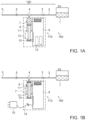
- System 100 which is illustrated in Figs. 1A and 1B , is a stand-alone electro-mechanical infusion system that creates pulsed flow having high volume and high velocity. According to some embodiments of the present invention system 100 may allow a user to set the volume of the pulse, the frequency of the pulses and the pulse velocity.
- system 100 may include a tubing system 120 having an inlet 2 connected to an external reservoir 1 adapted to contain infusion fluids and an outlet 6 connected to a catheter (not illustrated).
- External reservoir 1 may be a fluid medication reservoir; solid, semi-solid container or a bag.
- System 100 may be an automatic pulsed flow generation device 110.
- tubing system 120 may be a disposable tubing system.
- Tubing system 120 may further include a check valve 3 proximate to inlet 2 and an anti-siphon check valve 5 proximate to outlet 6.
- Automatic pulse flow generation device 110 may include an internal reservoir 7, for example, in a form of a tube of a syringe, and a bidirectional pump 12.
- Bidirectional pump 12 may include a piston (as illustrated in Fig. 1A ) and a pulse actuation apparatus 8. It should be understood by those skilled in the art that the piston illustrated in Fig. 1A is given as an example only, and that other bidirectional pumps are in the scope of the present invention.
- automatic pulsed flow generation device 110 may be programmable by a user such as a medical team and/or a patient.
- automatic pulsed flow generation device 110 may be pre-set.
- Bidirectional pump 12 may be configured to pump infusion fluid from external reservoir 1 to internal reservoir 7 and further pump an infusion fluid pulse from internal reservoir 7 to be injected by the catheter, the infusion liquid pulse may have a volume of at least 2 ml and a velocity of at least 5 ml/min at pulse cycle frequency of 15 minutes or longer.
- An exemplary automatic pulsed flow generation device 110 may comprise an internal pump reservoir 7, such as a syringe, a piston 12 and a pulse actuation apparatus 8. During the bidirectional operation syringe 7 is filled and emptied during each cycle.
- Device 100 may further include a controller (not illustrated) configured to control bidirectional pump 12 and optionally also valves 3 and 5.
- the controller may control pulse actuation apparatus 8 included in pump 12 to control the velocity of the infusion pulse, for example to generate or provide an infusion pulse having a velocity of 5-30 ml/min (milliliter/minute).
- the controller may control pulse actuation apparatus 8 included in pump 12 to control the volume of the infusion pulse, for example, to generate or provide an infusion pulse having a volume of 2-15 ml (milliliter).
- the controller may control pulse actuation apparatus 8 included in pump 12 to control a frequency at which the pulses are injected, for example, the pulse may be given to a patient between once in every 90 minutes to once in every 10 minutes.
- the controller may further control the internal pressure at which the pulse is injected.
- a relatively high pressure, for example, of at least 1.5 or 2 bar may be required to produce a pulse at a velocity of at least 5 ml/min.
- the controller may control pump 12 to build a pressure of at least 2 bar in order to inject the pulse at at least 5 ml/min.
- the controller may control pump 12 to pump infusion fluid from external reservoir 1 to internal reservoir 7 while opening valve 3.
- the controller may control pump 12 to generate an infusion fluid pulse by pumping the infusion fluid from internal reservoir 7 to outlet 6 while opening anti siphon check valve 5.
- internal reservoir 7 is filled using energy provided by the flow from external reservoir 1. It would be appreciated by those skilled in the art that other mechanisms may be used for filling internal reservoir 7 with fluid received from external reservoir 1.
- pulsed flow generation device 110 may be operated electromechanically, through an electric motor or solenoid (not shown) which may be controlled by an electronic controller (not shown) in actuation apparatus 8.
- the electronic controller may be programmable or preprogrammed to allow adapting the pulses frequency, the volume and velocity of each pulse of fluid and other parameters in order to tailor these parameters to the needs of each patient.
- device 100 may include more than one controller.
- actuation apparatus 8 may comprise a controller for controlling the pulses frequency (not shown).
- actuation apparatus 8 may comprise another or an additional controller such as a pulsed flow volume controller.
- actuation apparatus 8 may comprise a flow velocity controller. It would be appreciated by those skilled in the art that other controllers, optionally of other parameters, may be used.
- Pulsed flow generation device 110 may pump a defined volume of fluid, for example, 10 ml, received from external reservoir 1 to an internal pump reservoir, such as syringe 7.
- Pump 12 e.g., a piston
- Pump 12 may then pump out that defined volume or a smaller volume, for example, 5 ml, entirely or partially, into a catheter (not shown) placed in the body of the patient.
- These pumping operations may be performed continuously at a selected frequency, for example, once every 60 minutes.
- both internal reservoir 7 and pump 12 may be parts of a disposable syringe set.
- Device operation parameters can be preset during manufacturing (pre-programmed) or, in a programmable version, the medical team may have the option to select and set the operational parameters of the device during the course of the therapy and to permanently lock them when needed.
- the device may be an ambulatory type powered by batteries 13. However a stationary device can be used where the patient is unlikely to be moved. Energy may then be supplied through a cord 14 connected to the building electric supply via a transformer-rectifier 15.
- system may be operated manually by the patient and/or medical team in addition to the automatically pulses delivery. In some embodiments, the system may be operated manually only by the patient and/or medical team. In some embodiments, when operated manually system 100 may be configured to supply an infusion liquid pulse having a volume of at least 2 ml and a velocity of at least 5 ml/min.
- Fig.1A represents an electromechanical pulsed flow generation device 110.
- Tubing system 120 compromise inlet tube 2 that may be connected at one end to external reservoir 1 by use of a standard fitting and on the other end to check valve 3.
- a connector such as a T shape connector 4
- Outlet port 6 may be positioned after said anti-siphon check valve.
- Outlet port 6 may have standard fitting to be connected to an NB catheter placed in the patient body or any other fluid insertion apparatus known in the art.
- the remaining branch of T connector 4 opens into variable volume container such as a standard disposable syringe 7. It would be appreciated by those skilled in the art that actuation apparatus 8 of device 110 may be disposable or reusable, while tubing system 120 and external reservoir 1 are usually disposable components.
- Internal reservoir 7 may be connected to electromechanical programmable actuation apparatus 8 by mounting the reservoir barrel 11 onto a holder 9 and the piston rod 12 to the pull lever 10.
- Check valve 3 may further prevent back-flow of fluids from connector 4 to external reservoir 1.
- Anti-siphon check valve 5 may further prevent gravity flow from reservoir 1 to exit port 6 and prevents back flow from exit port 6 to connector 4.
- Pull lever 10 of actuation apparatus 8 may move linearly only along one axis of pump 12 (in the direction of the double-headed arrow indicated in Figs. 1A and 1B ) so that when pull lever 10 moves in a first direction, the internal volume of internal reservoir 7 increases and when pull lever 10 moves in a second direction the volume of internal reservoir 7 decreases.
- the pump e.g., piston
- Movement of pull lever 10 in said second direction applies pressure on the fluid in internal reservoir 7 that pumps out the medication from said internal reservoir 7 to the patient through anti-siphon check valve 5 and through outlet port 6.
- Electronic programmable means of actuation apparatus 8 may enable to determine the volume that to be pumped into syringe 7 every and each movement cycle of pull lever 10 (e.g., 15 ml) in the first direction and the volume that is pumped out of syringe 7 (e.g., 5 ml) every and each movement of pull lever 10 in the second direction.
- Frequency of pull lever 10 movement may also be pre-set and controlled.
- the speed of movement of pull lever 10 may also be pre-set and controlled.
- actuation apparatus 8 may be equipped with electronic means to store and analyze the infusion data and to sound an alarm when data received and recorded is outside pre-defined limits. For example, when the total pulsed flow volume is beyond a predefined maximum dosage.
- Fig. 1B shows the electromechanical pulse infusion system 100, presenting the system in a situation where the pull lever 10 has moved in the second direction to its extremity, i.e. pumping out the fluids within syringe 7.
- device 110 may be arranged to receive power from a wall socket, using a transformer-rectifier 15 and a cable 14.
- Fig. 1C is a schematic illustration of a stationary pulse infusion system 100 according to some embodiments of the invention.
- External reservoir 1 in a form of a plastic bag may be placed on a pole near or above a patient's bad.
- Tubing system 120 may connect the bag to system 100 and may further be connected to a catheter.
- System 100 may further include a manual pulse flow controlling device 260, allowing the patient and/or medical team member to manually control pulse flow generation device 110 to give an additional pulse of medication upon the patient's request (regardless of the administration frequency determined and programed in the automatic pulse flow generation device).
- System 100 may be configured to deliver manual pulse flow only.
- FIG. 1D is a schematic illustration of an ambulatory pulse infusion system 100 according to some embodiments of the invention.
- External reservoir 1 may be placed inside or attached to the body of system 100 to be carried out by the patient.
- An ambulatory system 100 may further include a tubing system 120 and a manual pulse flow controlling device 260 as disclosed above.
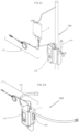
- FIG. 2 is a schematic drawing of another electromechanical embodiment of the present invention.
- tubing 2 is connected to an inlet port 52 through an optional one-way valve 3.
- a connector such as a T shape connector 4 leads to an anti-siphon check valve 5 and an exit port 20.
- Pulse flow generation device 110 is also connected to the 'T' connector 4. Pulsed flow generation device 110 is equipped with a pump (e.g., piston) 12, an optional spring 26, an electric actuation apparatus 8 and a sensor (proximity switch) 30. Syringe 7 is filled and discharges through connector 4.
- a pump e.g., piston
- a spring e.g., spring
- a sensor e.g., proximity switch
- a fluid such as fluid medicament
- a fluid may flow from an infusion pump (not shown) through inlet port 52, and through valve 3.
- the fluid flowing into tube 2 between valves 3 and 5 may cause pressure build-up and push piston 12 in the first direction to increase the volume of fluid that may be contained in syringe 7.
- actuation apparatus 8 causes piston 12 to start moving in a second direction to pump out the fluid contained in syringe 7.
- pressure in tube 2 increases until pressure check valve 5 is opened, and a pulse of fluid may flow through the pressure-activated check valve 5 and may exit into a patient's body through outlet port 20.
- actuation apparatus 8 retracts to its original position after a preset delay, typically between 1 and 3 seconds. The reduced fluid pressure in syringe 7 allows new fluid therein thus starting a new cycle.
- spring 26 may not be required and other buffer mechanisms may be used. It would be further realized that a buffer may not be required at all.
- Means are provided to change the position of sensor or proximity switch 30, thus adjusting the pulsed fluid volume. Other means for adjusting the volume of fluid released in each pulse may be used.
- sensor 30 is a component which continuously monitors piston 12 position and transmits signals to a programmable controller (PEC) (not illustrated).
- PEC programmable controller
- the PEC is easily set to a desired fluid volume per pulse, and additionally any desired time delay can be programmed therein.
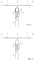
- FIG. 3 is an illustration of a pulse flow generation device 110 according to some embodiments of the invention.
- Device 110 of Fig. 3 is almost identical to that seen in Fig. 2 except that no sensor (proximity switch) is provided.
- a PEC (not shown) controls the actuation apparatus 8, generating an electric signal according to a time interval set by the medical team. The signal connects power to the actuation apparatus 8 to move in a second direction to pump out fluid from syringe 7 and the pulse is generated exactly as described with reference to Fig. 2 .
- the time interval set in the PEC may be easily changed, and thus different pulsed volumes can be ejected while using the same basic flow rate.
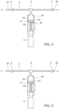
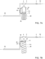
- FIG. 4 illustrates an embodiment provided with a syringe 7 having an internal container 34 made of an elastic material, for example of silicone rubber positioned inside a rigid container 32.
- Internal container 34 has a controlled volume and is beneficial in preventing any leak of a fluid into the pump mechanism. Furthermore, internal container 34 reduces the area of contact between the fluid and parts of the pump. In all other respects the present embodiment is identical to the embodiment described with reference to Fig. 2 .
- Fig. 5 which illustrates an embodiment similar to that shown in Fig. 4 , except that a PEC (not shown) comprised within actuation apparatus 8 creates an electric signal according to a time interval set by the user. Therefore switch or sensor 30 seen in Fig. 4 may not be required.
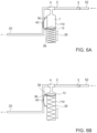
- Figs. 6A and 6B illustrate a mechanical pulse device, so there is no electric actuation apparatus 8 as was seen in previous embodiments.
- Tubing 2 is connected to an inlet port 52 through an optional one-way valve 3.
- a connector such as T shaped connector 4 leads to a pressure-activated check valve 40 and an exit port 20.
- Pulsed flow generation device 110 is also connected to the 'T' connector 4. Pulsed flow generation device 110 may be equipped with a piston 12, a spring 26, and a projection 38.
- the normally closed valve 40 thus prevents fluid discharge through outlet port 20, wherefore incoming fluid accumulates in syringe 7.
- Valve 40 may be actuated by a lever 36 when pushed by projection 38.
- a fluid such as a fluid medicament may flow from an infusion pump (not seen) through inlet port 52.
- piston 12 moves in a first direction to increase the volume of fluid contained in syringe 7 until projection 38 contacts a part of lever 36, opening valve 40 and forcing a pulse of liquid through port 20.
- Means are provided to change the position of the projection 38 relative to the dimensions of pulse flow generation device 110, thus adjusting the pulse volume.
- two projections, lower and upper may be used instead of projection 38.
- the lower projection can be adjusted by the medical team member for varying the pulse volume. It would be appreciated that other means for adjusting the pulsed volume may be used.
- syringe 7 comprises an internal container made of an elastic material, for example of silicone rubber
- syringe 7 comprises an internal container made of an elastic material, for example of silicone rubber
- FIG. 8 is an illustration of an arrangement of a mechanical pulse device similar to the devices seen in Figs. 6A and 6B .
- An elastic band 42 may be connected to projections 44 while being tensioned over a piston rod 46.
- the elastic band 42 thus replaces the compression spring 26 seen in previous embodiments, and being external can be easily replaced when necessary.
- the pulsed flow generation device 110 can be an integral part of an infusion pump or may be connectable to any infusion pump known in the art.
- Fig. 9 is a flowchart of a method for converting a constant flow into a pulse flow which is an example useful for understanding the invention but which does not form part of the claimed subject matter. The method comprising the following steps:
- a fluid such as an infusion medicament
- the fluid may than pass through a one-way valve to prevent the fluid from returning to the external reservoir [Block 1010].
- the fluid flowing form the external reservoir is prevented from returning to the reservoir by the one-way valve, and cannot pass another valve, such as an anti-siphon check valve, the fluid enters and contained in an internal reservoir, such as a syringe [Block 1020].
- an actuation apparatus applies pressure on the fluid contained in the reservoir and thus releases the contained fluid in an at least one pulsed flow [Block 1030].
- the volume of fluid contained in the internal reservoir may be released in several consecutive pulses, each pulse having a volume which is relative to the number of pulses. For example, if the reservoir has been filled with 30ml of fluid medication, it may be released in one pulse of 30ml, or may be released in 3 consecutive pulses of 10ml. each.
- Device 110 may include, a device body 201, made for example, from a rigid polymer, a screen 202, a keyboard 203 and a housing 204 for holding an internal reservoir and bidirectional pump, for example, in the form of syringe 250 illustrated in Fig. 11 .
- Housing 204 may include holder 214 for holding the syringe.
- holder 214 may include more than one component, for example, an internal reservoir holder 213 and a bidirectional pump holder 212.
- a device body 201 made for example, from a rigid polymer
- a screen 202 for example, a keyboard 203 and a housing 204 for holding an internal reservoir and bidirectional pump, for example, in the form of syringe 250 illustrated in Fig. 11 .
- Housing 204 may include holder 214 for holding the syringe.
- holder 214 may include more than one component, for example, an internal reservoir holder 213 and a bidirectional pump holder 212.
- the internal reservoir holder 213 holds a syringe barrel and a bidirectional pump holder 212 holds a plunger of a piston.
- Housing 204 may further include a lever 211 to support the movement of the piston and a switch 215 for verifying that the internal reservoir was inserted into holder 214 and that a compatible internal reservoir is being used, for example in order to avoid administration errors such as overdosing or underdoing due to an insertion of a wrong internal reservoir.
- Fig. 10B is a high level block diagram that includes some of the components of device 110.
- Device 110 may further include a motor 220 (e.g., a servo motor) and a transmission 221 for transmitting a translational (or rotational) movement to lever 211 positioned over a shaft 222.
- Motor 220 may be powered by a battery 225 via a power supply unit 224.
- Device 110 may further include a controller 230.
- Controller 230 may be configured to control at least some of the elements included in system 100 and device 110, for example, motor 220 and lever 211. Controller 230 may further be configured to control the bidirectional pump (e.g., pumps 12 and 251). Controller 230 may include any computation platform that may be configured to control system 100 according to code saved in a non-transitory memory associated with the controller, which when executed causes system 100 to perform the invention. Additionally or alternatively controller 230 may execute instructions received from a user using a user interface associated with controller 230, for example, using keyboard 203 and/or screen 202. Screen 202 may be a touch screen or any other display known in the art.
- Controller 230 may include a processor (e.g., a CPU, microcontroller, programmable logic controller (PLC) and the like), a non-transitory memory for storing codes that when executed by the processor perform the invention. Controller 230 may be associated with a user interface (e.g., a graphical user interface) that may include any devices that allow a user to communicate with the controller.
- a processor e.g., a CPU, microcontroller, programmable logic controller (PLC) and the like
- PLC programmable logic controller
- Controller 230 may be associated with a user interface (e.g., a graphical user interface) that may include any devices that allow a user to communicate with the controller.
- Controller 230 may control system 100 and device 110 to pump infusion fluid from the external reservoir to the internal reservoir and further pump an infusion fluid pulse from the internal reservoir to be injected by the catheter, the infusion liquid pulse may have a volume of at least 2 ml and a velocity of at least 5 ml/min.
- a syringe 250 may include an internal reservoir 253, for example, in the form of a barrel and a bidirectional pump 251, for example, in the form of a plunger pump and a piston located inside internal reservoir 253.
- Internal reservoir 253 may have a volume of 2-50 ml, for example, 15 ml.
- a Piston may be connected to a plunger pump (as illustrated) to form the bidirectional pump 251.
- Bidirectional pump 251 may be configured to pump infusion fluid from external reservoir, such as reservoir 1, to internal reservoir 253 and further pump an infusion fluid pulse from internal reservoir 253 to be injected by the catheter, the infusion liquid pulse may have a volume of at least 2 ml and a velocity of at least 5 ml/min.
- Controller 230 may be configured to cause bidirectional pump 251 to pump infusion liquid to or from internal reservoir 253, for example, by controlling motor 220 to move lever 211 to push or pull the plunger of pump 251.
- Syringe 250 may further include an indicator 254 for identifying the syringe, for example, in order to verify that the syringe is in the correct volume or contains the correct substance.
- the internal reservoir and the bidirectional pump are included in a single device, syringe 250.
- the internal reservoir and the bisectional pump may each be a standalone component connected together via tubing system.
- the bidirectional pump may be any pump configured to pump liquids to and from a reservoir.
- the bidirectional pump may include: a plunger pump (as illustrated), a peristaltic pump, a roots-type pump or any other pump known in the art.
- the internal reservoir may include any container configured to hold infusion fluids.
- the internal reservoir may have a constant volume or a changeable volume that may vary with the amount of infusion fluid in the reservoir.
- Figs. 12 and 13 are illustrations of tubing systems 120 according to some embodiments of the invention.
- Both systems 120 of Figs. 12 and 13 may include one-way check valve 123, Y connector 124, syringe connector 122, patient clamp 125, filer 126, anti-siphon one way check valve 127 and outlet port 131.
- the tubing system of Fig. 12 further includes piercing device 121 at the inlet port proximate to valve 123.
- the tubing system of Fig. 13 may further include an external reservoir 130, a medical team clamp 128 and a filling port 129.
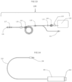
- Fig. 14 is an illustration of a manual controller (e.g., controller 260) for controlling device 110 to apply a Patient Control Analgesia (PCA) and/or a Clinician Bolus by operating system 100 to inject infusion liquid pulse, for example, upon a request from the patient or a decision made by a medical professional.
- the injected infusion liquid pulse may have a volume of at least 2 ml and a velocity of at least 5 ml/min.
- the manual controller may include a housing 261, a push button 262 to be pushed by the patient, a wire 263 and a plug 264.
- the manual controller may be configured to cause an application of a predetermined amount of medication at a predetermined velocity, for example, 3 ml at 5 ml/min when the patient/clinician pushes button 262, regardless of the frequency of infusion liquid pulse programed in automatic device 110.
- the manual controller may be operated in addition to the automatic administration programed in automatic device 110 or separately when no administration is programed in automatic device 110. It should be appreciated by those skilled in the art that in order to avoid overdosing, a lock time period during which additional pulses cannot be initiated by the patient may be set. It should be further appreciated that the predetermined amount of medication released by the patient and/or clinician may be reduced from the total volume of liquid in the internal reservoir and thus from the total volume of medication given to the patient in a given time interval.
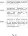
- Fig. 15 is a flowchart of a method of administrating an infusion liquid pulse which is an example useful for understanding the invention but which does not form part of the claimed subject matter.
- the method of Fig. 15 may be performed by pulse infusion system 100, disclosed above.
- the method may include automatically pumping an infusion liquid from an external reservoir (e.g., reservoir 1) to an internal reservoir (e.g., internal reservoirs 7 or 253) included in a pulse infusion system, the external reservoir may be adapted to contain infusion fluids.
- System 100 may automatically pump the infusion liquid from the external reservoir every predetermined amount of time, for example, at least once in every 90 minutes, or every shorter periods of time.
- the infusion liquid may be pump using bidirectional pump.
- the method may include automatically generating the infusion liquid pulse by pumping a predetermined volume of an infusion liquid from the internal reservoir and injecting the predetermined volume at a predetermined velocity, the predetermined volume may be at least 2 ml and the predetermined velocity may be at least 5 ml/min.
- the infusion liquid pulse may be generated using the bidirectional pump.
- the infusion liquid pulse may be injected to a patient via a catheter.
- the predetermined volume may be between 2 ml to 15 ml.
- the predetermined velocity may be between 5 ml/min to 30 ml/min.
- the pressure of the infusion liquid pulse inside the internal reservoir may be any predetermined pressure to enable injecting the predetermined volume at a predetermined velocity, for example in the range of 2-4 bars.
- the method may include manually generating the infusion liquid pulse by pumping a predetermined volume of an infusion liquid from the internal reservoir and injecting the predetermined volume at a predetermined velocity, the predetermined volume may be at least 2 ml and the predetermined velocity may be at least 5 ml/min.
- the infusion liquid pulse may be generated by controlling a manual controller (e.g., by pushing button 262) to operate the bidirectional pump.
- the infusion liquid pulse may be injected to a patient via a catheter.
- the predetermined volume may be between 2 ml to 15 ml.
- the predetermined velocity may be between 5 ml/min to 30 ml/min.
- the pressure of the infusion liquid pulse inside the internal reservoir may be any predetermined pressure to enable injecting the predetermined volume at a the predetermined velocity, for example, in the range of 2-4 bars.
- the method may include repeating the automatic generation of the infusion liquid pulse every predetermined duration of time, for example, at least once in every 90 minutes. In some embodiments, the method may include repeating the automatically pumping the infusion liquid from the external reservoir and automatic generation of the infusion liquid pulse every the same predetermined amount of time.
Landscapes
- Health & Medical Sciences (AREA)
- Vascular Medicine (AREA)
- Engineering & Computer Science (AREA)
- Anesthesiology (AREA)
- Biomedical Technology (AREA)
- Heart & Thoracic Surgery (AREA)
- Hematology (AREA)
- Life Sciences & Earth Sciences (AREA)
- Animal Behavior & Ethology (AREA)
- General Health & Medical Sciences (AREA)
- Public Health (AREA)
- Veterinary Medicine (AREA)
- Physics & Mathematics (AREA)
- Fluid Mechanics (AREA)
- Infusion, Injection, And Reservoir Apparatuses (AREA)
Claims (8)
- Pulsinfusionssystem (100) umfassend wie folgt:ein Schlauchsystem (120), das einen Eingang (2) hat, der mit einem externen Sammelbehälter (1) verbunden ist, welcher dazu adaptiert ist, um Infusionsfluide zu enthalten, und das einen Ausgang (6) hat, der mit einem Katheter verbunden ist, wobei das Schlauchsystem (120) ferner ein Rückschlagventil (3) umfasst, das in der Nähe des Eingangs (2) ist, und ein Anti-Siphon-Rückschlagventil (5), das in der Nähe des Ausgangs (6) ist; undeine automatische Pulsfluss-Generierungsvorrichtung (110) umfassend wie folgt:einen internen Sammelbehälter (7);einen Controller (230); undeine bidirektionelle Pumpe (12), die von dem Controller (230) gesteuert wird, und umfassend einePuls-Betätigungsvorrichtung (8), wobei die bidirektionelle Pumpe (12) dazu konfiguriert ist, um Infusionsfluid aus dem externen Sammelbehälter (1) in den internen Sammelbehälter (7) zu pumpen und ferner einen Infusionsfluidpuls, welcher von dem Katheter zu injizieren ist, aus dem internen Sammelbehälter (7) zu pumpen, wobei der Infusionsflüssigkeitspuls ein Volumen von mindestens 2 Millilitern (ml) und eine Geschwindigkeit von mindestens 5 Millilitern/Minute (ml/min) hat,wobei der Controller (230) die Puls-Betätigungsvorrichtung (8) zu steuern hat, um die Geschwindigkeit des Infusionspulses zu steuerndadurch gekennzeichnet, dass:die Betätigungsvorrichtung (8) einen Zughebel (10) umfasst, der entlang einer Achse der bidirektionellen Pumpe (12) bewegt wird, wobei gilt, dass, wenn der Zughebel (10) in eine erste Richtung bewegt wird,das Volumen des internen Sammelbehälters (7) zunimmt und dass, wenn der Zughebel (10) in eine zweite Richtung bewegt wird, das Volumen des internen Sammelbehälters (7) abnimmt, undwobei der Controller (230) dazu konfiguriert ist, um für jeden Bewegungszyklus jeweils das gepumpte Volumen zur Bewegung des Zughebels (10) in die erste Richtung zu bestimmen und jeweils das gepumpte Volumen zur Bewegung des Zughebels (10) in die zweite Richtung zu bestimmen.
- Pulsinfusionssystem (100) nach Anspruch 1, wobei der Controller (230) ferner dazu konfiguriert ist, um von einem Benutzer Werte hinsichtlich dem Volumen und der Geschwindigkeit zu empfangen.
- Pulsinfusionssystem (100) nach Anspruch 1, wobei der Controller (230) ferner dazu konfiguriert ist, um eine Frequenz, mit der die Pulse injiziert werden, zu steuern.
- Pulsinfusionssystem (100) nach Anspruch 1, wobei der Controller (230) ferner dazu konfiguriert ist, um das Rückschlagventil (3) und das Anti-Siphon-Rückschlagventil (5) zu steuern.
- Pulsinfusionssystem (100) nach Anspruch 1, wobei der Controller die bidirektionelle Pumpe steuert, sodass diese den Infusionsflüssigkeitspuls mit einer Geschwindigkeit von 5 ml/min bis 30 ml/min erzeugt.
- Pulsinfusionssystem (100) nach Anspruch 1, wobei der Controller die bidirektionelle Pumpe steuert, sodass diese den Infusionsflüssigkeitspuls mit einem Volumen von 2 ml/min bis 15 ml/min erzeugt.
- Pulsinfusionssystem (100) nach Anspruch 1, wobei die automatische Pulsstrom-Generierungsvorrichtung (110) dazu konfiguriert ist, um den Infusionsflüssigkeitspuls mit einer Frequenz von jeweils einmal alle 90 Minuten bis jeweils einmal alle 10 Minuten zu erzeugen.
- Pulsinfusionssystem (100) nach Anspruch 1 ferner umfassend einen manuell betriebenen Controller (260) zum manuellen Steuern der automatischen Pulsstrom-Generierungsvorrichtung (110) zusätzlich zur automatischen Pulsbereitstellung, um einen Infusionsflüssigkeitspuls zu injizieren.
Applications Claiming Priority (2)
| Application Number | Priority Date | Filing Date | Title |
|---|---|---|---|
| US14/685,711 US10086137B2 (en) | 2010-07-22 | 2015-04-14 | Pulse infusion device system and method |
| PCT/IL2016/050388 WO2016166754A1 (en) | 2015-04-14 | 2016-04-13 | Pulse infusion device and method |
Publications (3)
| Publication Number | Publication Date |
|---|---|
| EP3283144A1 EP3283144A1 (de) | 2018-02-21 |
| EP3283144A4 EP3283144A4 (de) | 2018-10-10 |
| EP3283144B1 true EP3283144B1 (de) | 2025-06-04 |
Family
ID=57125982
Family Applications (1)
| Application Number | Title | Priority Date | Filing Date |
|---|---|---|---|
| EP16779710.9A Active EP3283144B1 (de) | 2015-04-14 | 2016-04-13 | Pulsinfusionsvorrichtung |
Country Status (2)
| Country | Link |
|---|---|
| EP (1) | EP3283144B1 (de) |
| WO (1) | WO2016166754A1 (de) |
Families Citing this family (1)
| Publication number | Priority date | Publication date | Assignee | Title |
|---|---|---|---|---|
| CN109364330A (zh) * | 2018-11-09 | 2019-02-22 | 潍坊科技学院 | 一种自动换药输液装置 |
Family Cites Families (5)
| Publication number | Priority date | Publication date | Assignee | Title |
|---|---|---|---|---|
| US4562829A (en) * | 1983-02-28 | 1986-01-07 | E. R. Squibb & Sons, Inc. | Strontium-rubidium infusion system |
| CN102119252B (zh) * | 2008-06-06 | 2015-02-18 | 拜耳医疗保健公司 | 用于向患者递送流体注射药丸以及处理有害流体的装置和方法 |
| US20130123703A1 (en) * | 2010-07-22 | 2013-05-16 | Ofer Shay | Pulse infusion device system and method |
| US10086137B2 (en) * | 2010-07-22 | 2018-10-02 | Medical Flow Systems Ltd | Pulse infusion device system and method |
| US9144644B2 (en) * | 2011-08-02 | 2015-09-29 | Baxter International Inc. | Infusion pump with independently controllable valves and low power operation and methods thereof |
-
2016
- 2016-04-13 WO PCT/IL2016/050388 patent/WO2016166754A1/en not_active Ceased
- 2016-04-13 EP EP16779710.9A patent/EP3283144B1/de active Active
Also Published As
| Publication number | Publication date |
|---|---|
| EP3283144A1 (de) | 2018-02-21 |
| WO2016166754A1 (en) | 2016-10-20 |
| EP3283144A4 (de) | 2018-10-10 |
Similar Documents
| Publication | Publication Date | Title |
|---|---|---|
| US20130123703A1 (en) | Pulse infusion device system and method | |
| US10780221B2 (en) | Pulse infusion device system and method | |
| RU2578540C2 (ru) | Управляемое пациентом устройство для введения жидкого лекарственного средства (варианты) | |
| US6656159B2 (en) | Dispenser for patient infusion device | |
| US8114064B2 (en) | Infusion device with piston pump | |
| EP3436112B1 (de) | Pulsinfusionsvorrichtungssystem und -verfahren | |
| JP7511559B2 (ja) | 医療用流体送達装置およびシステム、ならびに作動方法 | |
| US10279129B2 (en) | Pulse infusion device system and method | |
| EP3055002B1 (de) | Patientengesteuerte arzneimittelverabreichungsvorrichtung mit sperre für grossvolumigen bolus | |
| EP3283144B1 (de) | Pulsinfusionsvorrichtung | |
| EP4651921A1 (de) | Verfahren und vorrichtung zur kontrollierten infusion über impulse mit vordefiniertem diskretem bolusvolumen zur erzielung einer pharmakokinetischen reaktion auf eine kontrollierte infusion |
Legal Events
| Date | Code | Title | Description |
|---|---|---|---|
| STAA | Information on the status of an ep patent application or granted ep patent |
Free format text: STATUS: THE INTERNATIONAL PUBLICATION HAS BEEN MADE |
|
| PUAI | Public reference made under article 153(3) epc to a published international application that has entered the european phase |
Free format text: ORIGINAL CODE: 0009012 |
|
| STAA | Information on the status of an ep patent application or granted ep patent |
Free format text: STATUS: REQUEST FOR EXAMINATION WAS MADE |
|
| 17P | Request for examination filed |
Effective date: 20171113 |
|
| AK | Designated contracting states |
Kind code of ref document: A1 Designated state(s): AL AT BE BG CH CY CZ DE DK EE ES FI FR GB GR HR HU IE IS IT LI LT LU LV MC MK MT NL NO PL PT RO RS SE SI SK SM TR |
|
| AX | Request for extension of the european patent |
Extension state: BA ME |
|
| DAV | Request for validation of the european patent (deleted) | ||
| DAX | Request for extension of the european patent (deleted) | ||
| A4 | Supplementary search report drawn up and despatched |
Effective date: 20180907 |
|
| RIC1 | Information provided on ipc code assigned before grant |
Ipc: A61M 5/142 20060101AFI20180903BHEP Ipc: A61M 5/168 20060101ALI20180903BHEP Ipc: A61M 5/172 20060101ALI20180903BHEP |
|
| STAA | Information on the status of an ep patent application or granted ep patent |
Free format text: STATUS: EXAMINATION IS IN PROGRESS |
|
| 17Q | First examination report despatched |
Effective date: 20220609 |
|
| GRAP | Despatch of communication of intention to grant a patent |
Free format text: ORIGINAL CODE: EPIDOSNIGR1 |
|
| STAA | Information on the status of an ep patent application or granted ep patent |
Free format text: STATUS: GRANT OF PATENT IS INTENDED |
|
| GRAS | Grant fee paid |
Free format text: ORIGINAL CODE: EPIDOSNIGR3 |
|
| INTG | Intention to grant announced |
Effective date: 20250318 |
|
| GRAA | (expected) grant |
Free format text: ORIGINAL CODE: 0009210 |
|
| STAA | Information on the status of an ep patent application or granted ep patent |
Free format text: STATUS: THE PATENT HAS BEEN GRANTED |
|
| AK | Designated contracting states |
Kind code of ref document: B1 Designated state(s): AL AT BE BG CH CY CZ DE DK EE ES FI FR GB GR HR HU IE IS IT LI LT LU LV MC MK MT NL NO PL PT RO RS SE SI SK SM TR |
|
| REG | Reference to a national code |
Ref country code: GB Ref legal event code: FG4D |
|
| REG | Reference to a national code |
Ref country code: CH Ref legal event code: EP |
|
| REG | Reference to a national code |
Ref country code: DE Ref legal event code: R096 Ref document number: 602016092459 Country of ref document: DE |
|
| REG | Reference to a national code |
Ref country code: IE Ref legal event code: FG4D |
|
| REG | Reference to a national code |
Ref country code: NL Ref legal event code: MP Effective date: 20250604 |
|
| PG25 | Lapsed in a contracting state [announced via postgrant information from national office to epo] |
Ref country code: FI Free format text: LAPSE BECAUSE OF FAILURE TO SUBMIT A TRANSLATION OF THE DESCRIPTION OR TO PAY THE FEE WITHIN THE PRESCRIBED TIME-LIMIT Effective date: 20250604 Ref country code: ES Free format text: LAPSE BECAUSE OF FAILURE TO SUBMIT A TRANSLATION OF THE DESCRIPTION OR TO PAY THE FEE WITHIN THE PRESCRIBED TIME-LIMIT Effective date: 20250604 |
|
| REG | Reference to a national code |
Ref country code: LT Ref legal event code: MG9D |
|
| PG25 | Lapsed in a contracting state [announced via postgrant information from national office to epo] |
Ref country code: NO Free format text: LAPSE BECAUSE OF FAILURE TO SUBMIT A TRANSLATION OF THE DESCRIPTION OR TO PAY THE FEE WITHIN THE PRESCRIBED TIME-LIMIT Effective date: 20250904 Ref country code: GR Free format text: LAPSE BECAUSE OF FAILURE TO SUBMIT A TRANSLATION OF THE DESCRIPTION OR TO PAY THE FEE WITHIN THE PRESCRIBED TIME-LIMIT Effective date: 20250905 |
|
| PG25 | Lapsed in a contracting state [announced via postgrant information from national office to epo] |
Ref country code: PL Free format text: LAPSE BECAUSE OF FAILURE TO SUBMIT A TRANSLATION OF THE DESCRIPTION OR TO PAY THE FEE WITHIN THE PRESCRIBED TIME-LIMIT Effective date: 20250604 |
|
| PG25 | Lapsed in a contracting state [announced via postgrant information from national office to epo] |
Ref country code: BG Free format text: LAPSE BECAUSE OF FAILURE TO SUBMIT A TRANSLATION OF THE DESCRIPTION OR TO PAY THE FEE WITHIN THE PRESCRIBED TIME-LIMIT Effective date: 20250604 |
|
| PG25 | Lapsed in a contracting state [announced via postgrant information from national office to epo] |
Ref country code: HR Free format text: LAPSE BECAUSE OF FAILURE TO SUBMIT A TRANSLATION OF THE DESCRIPTION OR TO PAY THE FEE WITHIN THE PRESCRIBED TIME-LIMIT Effective date: 20250604 |
|
| PG25 | Lapsed in a contracting state [announced via postgrant information from national office to epo] |
Ref country code: RS Free format text: LAPSE BECAUSE OF FAILURE TO SUBMIT A TRANSLATION OF THE DESCRIPTION OR TO PAY THE FEE WITHIN THE PRESCRIBED TIME-LIMIT Effective date: 20250904 |
|
| PG25 | Lapsed in a contracting state [announced via postgrant information from national office to epo] |
Ref country code: LV Free format text: LAPSE BECAUSE OF FAILURE TO SUBMIT A TRANSLATION OF THE DESCRIPTION OR TO PAY THE FEE WITHIN THE PRESCRIBED TIME-LIMIT Effective date: 20250604 |
|
| PG25 | Lapsed in a contracting state [announced via postgrant information from national office to epo] |
Ref country code: NL Free format text: LAPSE BECAUSE OF FAILURE TO SUBMIT A TRANSLATION OF THE DESCRIPTION OR TO PAY THE FEE WITHIN THE PRESCRIBED TIME-LIMIT Effective date: 20250604 |
|
| PG25 | Lapsed in a contracting state [announced via postgrant information from national office to epo] |
Ref country code: PT Free format text: LAPSE BECAUSE OF FAILURE TO SUBMIT A TRANSLATION OF THE DESCRIPTION OR TO PAY THE FEE WITHIN THE PRESCRIBED TIME-LIMIT Effective date: 20251006 |
|
| REG | Reference to a national code |
Ref country code: AT Ref legal event code: MK05 Ref document number: 1799766 Country of ref document: AT Kind code of ref document: T Effective date: 20250604 |
|
| PG25 | Lapsed in a contracting state [announced via postgrant information from national office to epo] |
Ref country code: IS Free format text: LAPSE BECAUSE OF FAILURE TO SUBMIT A TRANSLATION OF THE DESCRIPTION OR TO PAY THE FEE WITHIN THE PRESCRIBED TIME-LIMIT Effective date: 20251004 |
|
| PG25 | Lapsed in a contracting state [announced via postgrant information from national office to epo] |
Ref country code: AT Free format text: LAPSE BECAUSE OF FAILURE TO SUBMIT A TRANSLATION OF THE DESCRIPTION OR TO PAY THE FEE WITHIN THE PRESCRIBED TIME-LIMIT Effective date: 20250604 Ref country code: SM Free format text: LAPSE BECAUSE OF FAILURE TO SUBMIT A TRANSLATION OF THE DESCRIPTION OR TO PAY THE FEE WITHIN THE PRESCRIBED TIME-LIMIT Effective date: 20250604 |
|
| PG25 | Lapsed in a contracting state [announced via postgrant information from national office to epo] |
Ref country code: CZ Free format text: LAPSE BECAUSE OF FAILURE TO SUBMIT A TRANSLATION OF THE DESCRIPTION OR TO PAY THE FEE WITHIN THE PRESCRIBED TIME-LIMIT Effective date: 20250604 |
|
| PG25 | Lapsed in a contracting state [announced via postgrant information from national office to epo] |
Ref country code: EE Free format text: LAPSE BECAUSE OF FAILURE TO SUBMIT A TRANSLATION OF THE DESCRIPTION OR TO PAY THE FEE WITHIN THE PRESCRIBED TIME-LIMIT Effective date: 20250604 |
|
| PG25 | Lapsed in a contracting state [announced via postgrant information from national office to epo] |
Ref country code: SK Free format text: LAPSE BECAUSE OF FAILURE TO SUBMIT A TRANSLATION OF THE DESCRIPTION OR TO PAY THE FEE WITHIN THE PRESCRIBED TIME-LIMIT Effective date: 20250604 Ref country code: RO Free format text: LAPSE BECAUSE OF FAILURE TO SUBMIT A TRANSLATION OF THE DESCRIPTION OR TO PAY THE FEE WITHIN THE PRESCRIBED TIME-LIMIT Effective date: 20250604 |
|
| PG25 | Lapsed in a contracting state [announced via postgrant information from national office to epo] |
Ref country code: IT Free format text: LAPSE BECAUSE OF FAILURE TO SUBMIT A TRANSLATION OF THE DESCRIPTION OR TO PAY THE FEE WITHIN THE PRESCRIBED TIME-LIMIT Effective date: 20250604 |
|
| REG | Reference to a national code |
Ref country code: DE Ref legal event code: R097 Ref document number: 602016092459 Country of ref document: DE |
|
| PLBE | No opposition filed within time limit |
Free format text: ORIGINAL CODE: 0009261 |
|
| STAA | Information on the status of an ep patent application or granted ep patent |
Free format text: STATUS: NO OPPOSITION FILED WITHIN TIME LIMIT |
|
| PG25 | Lapsed in a contracting state [announced via postgrant information from national office to epo] |
Ref country code: DK Free format text: LAPSE BECAUSE OF FAILURE TO SUBMIT A TRANSLATION OF THE DESCRIPTION OR TO PAY THE FEE WITHIN THE PRESCRIBED TIME-LIMIT Effective date: 20250604 |
|
| REG | Reference to a national code |
Ref country code: CH Ref legal event code: L10 Free format text: ST27 STATUS EVENT CODE: U-0-0-L10-L00 (AS PROVIDED BY THE NATIONAL OFFICE) Effective date: 20260416 |