EP3282885B1 - Joint mechanism of an application device of a cosmetic product, associated device, application method and manufacturing method - Google Patents
Joint mechanism of an application device of a cosmetic product, associated device, application method and manufacturing method Download PDFInfo
- Publication number
- EP3282885B1 EP3282885B1 EP16716601.6A EP16716601A EP3282885B1 EP 3282885 B1 EP3282885 B1 EP 3282885B1 EP 16716601 A EP16716601 A EP 16716601A EP 3282885 B1 EP3282885 B1 EP 3282885B1
- Authority
- EP
- European Patent Office
- Prior art keywords
- guiding
- path
- pin
- bracket
- axis
- Prior art date
- Legal status (The legal status is an assumption and is not a legal conclusion. Google has not performed a legal analysis and makes no representation as to the accuracy of the status listed.)
- Active
Links
Images

Classifications
-
- A—HUMAN NECESSITIES
- A45—HAND OR TRAVELLING ARTICLES
- A45D—HAIRDRESSING OR SHAVING EQUIPMENT; EQUIPMENT FOR COSMETICS OR COSMETIC TREATMENTS, e.g. FOR MANICURING OR PEDICURING
- A45D34/00—Containers or accessories specially adapted for handling liquid toiletry or cosmetic substances, e.g. perfumes
- A45D34/04—Appliances specially adapted for applying liquid, e.g. using roller or ball
-
- A—HUMAN NECESSITIES
- A45—HAND OR TRAVELLING ARTICLES
- A45D—HAIRDRESSING OR SHAVING EQUIPMENT; EQUIPMENT FOR COSMETICS OR COSMETIC TREATMENTS, e.g. FOR MANICURING OR PEDICURING
- A45D40/00—Casings or accessories specially adapted for storing or handling solid or pasty toiletry or cosmetic substances, e.g. shaving soaps or lipsticks
- A45D40/22—Casings characterised by a hinged cover
-
- A—HUMAN NECESSITIES
- A45—HAND OR TRAVELLING ARTICLES
- A45D—HAIRDRESSING OR SHAVING EQUIPMENT; EQUIPMENT FOR COSMETICS OR COSMETIC TREATMENTS, e.g. FOR MANICURING OR PEDICURING
- A45D40/00—Casings or accessories specially adapted for storing or handling solid or pasty toiletry or cosmetic substances, e.g. shaving soaps or lipsticks
- A45D40/26—Appliances specially adapted for applying pasty paint, e.g. using roller, using a ball
-
- A—HUMAN NECESSITIES
- A45—HAND OR TRAVELLING ARTICLES
- A45D—HAIRDRESSING OR SHAVING EQUIPMENT; EQUIPMENT FOR COSMETICS OR COSMETIC TREATMENTS, e.g. FOR MANICURING OR PEDICURING
- A45D40/00—Casings or accessories specially adapted for storing or handling solid or pasty toiletry or cosmetic substances, e.g. shaving soaps or lipsticks
- A45D40/26—Appliances specially adapted for applying pasty paint, e.g. using roller, using a ball
- A45D40/262—Appliances specially adapted for applying pasty paint, e.g. using roller, using a ball using a brush or the like
- A45D40/265—Appliances specially adapted for applying pasty paint, e.g. using roller, using a ball using a brush or the like connected to the cap of the container
-
- A—HUMAN NECESSITIES
- A45—HAND OR TRAVELLING ARTICLES
- A45D—HAIRDRESSING OR SHAVING EQUIPMENT; EQUIPMENT FOR COSMETICS OR COSMETIC TREATMENTS, e.g. FOR MANICURING OR PEDICURING
- A45D34/00—Containers or accessories specially adapted for handling liquid toiletry or cosmetic substances, e.g. perfumes
- A45D2034/002—Accessories
-
- A—HUMAN NECESSITIES
- A45—HAND OR TRAVELLING ARTICLES
- A45D—HAIRDRESSING OR SHAVING EQUIPMENT; EQUIPMENT FOR COSMETICS OR COSMETIC TREATMENTS, e.g. FOR MANICURING OR PEDICURING
- A45D40/00—Casings or accessories specially adapted for storing or handling solid or pasty toiletry or cosmetic substances, e.g. shaving soaps or lipsticks
- A45D2040/0006—Accessories
-
- A—HUMAN NECESSITIES
- A45—HAND OR TRAVELLING ARTICLES
- A45D—HAIRDRESSING OR SHAVING EQUIPMENT; EQUIPMENT FOR COSMETICS OR COSMETIC TREATMENTS, e.g. FOR MANICURING OR PEDICURING
- A45D2200/00—Details not otherwise provided for in A45D
- A45D2200/10—Details of applicators
- A45D2200/1072—Eyeliners
Definitions
- This invention relates to a joint mechanism of an application device of a cosmetic product, comprising a first part having a rib and a second part carrying a bracket receiving the rib, said first part being mobile in rotation with respect to said second part about an axis.
- the application device is intended to package and to accurately apply a cosmetic product on a surface of the body of a user, such as the skin or the hair of the user.
- the cosmetic product is advantageously a makeup or care product such as an eye-liner, a mascara, a gloss or a lipstick.
- the cosmetic product has a fluid form.
- a cosmetic product is a product as defined in EC Regulation N° 1223/2009 of the European Parliament and the Council of November 30, 2009, relating to cosmetic products.
- a joint mechanism is known for example in document FR 2976166 A1 .
- This document describes an eye-liner comprising a joint between the handle and a part carrying the application tip.
- This joint consists of a pin extending between two flanges of the part carrying the application tip.
- US 4370989 discloses another example of an articulated rod shaped applicator for cosmetic products.
- the joint authorizes a pivoting of the application tip with respect to the handle facilitating the handling and the accuracy of the application.
- a first solution consists in masking the joint by providing a band comprising an outer skirt extending to below the pin.
- the band then forms an abutment that limits the amplitude of pivoting.
- a purpose of the invention is therefore to provide a joint mechanism according to claim 1 for an application device of a cosmetic product, that is simple and accurate to use while still having a very satisfactory external appearance.
- the invention has for object a mechanism of the aforementioned type, wherein one among the first part and the second part comprises at least one protruding pin, and in that the other among the first part and the second part defines a path for guiding the pin, the pin being inserted into the path for guiding, with the pin and the path for guiding being off-centered with respect to the axis.
- the mechanism according to the invention can include one or more of the following features, taken alone or in any technically possible combination:
- the invention also has for object an application device of a cosmetic product according to claim 11, comprising:
- the device according to the invention can include one or more of the following features, considered alone or in any combination that is technically possible:
- the invention also has for object a method according to claim 14 for applying cosmetic product on a surface of the body of a user including the following steps:
- the invention also has for object a method according to claim 15 for mounting a joint mechanism of an application device of cosmetic product, including the following steps:
- a first device 10 according to the invention is shown in Figure 1 .
- the device 10 is intended to condition a cosmetic product and to apply the cosmetic product on a body surface of a user, for example on the skin, or a keratin fiber of a user.
- the cosmetic product is advantageously a makeup or care product such as an eye-liner, a mascara, a gloss or a lipstick.
- the cosmetic product has a fluid form.
- the device 10 shown in figures 1, 2 and 3 comprises a gripping member 14, a rod carrier 16 carrying an applicator 18 and a joint mechanism 12 connecting the gripping member 14 to the rod carrier 16.
- the device 10 further comprises a receptacle 20, wherein the rod carrier 16 and the applicator 18 are intended to be introduced.
- the joint mechanism 12 comprises a first part 22 mobile jointly in rotation with the gripping member 14 and a second part 24 mounted mobile jointly in rotation with the rod carrier 16, with the first part 22 and the second part 24 being mounted mobile in rotation in relation to one another about an axis A-A'.
- the first part 22, in particular shown in figure 4 comprises an outer skirt 26, a rib 28 mounted in the center of the skirt 26, at least one protruding joint pin 30 and an upper portion 32.
- the outer skirt 26 extends between a free edge 34 and an upper edge 36 about a main axis B.
- the skirt 26 moves away from the axis B between the upper edge 36 and the free edge 34.
- the skirt 26 is substantially a cylinder about the axis B.
- the skirt 26 is hollow and delimits an inner surface 37.
- the skirt 26 defines notches 38. These notches 38 exit on its free edge 34.
- the skirt 26 comprises for example four notches 38.
- the notches 38 of the skirt 26 define inbetween at least one deformable tab 40.
- the deformable tab 40 is able to be moved away from and/or brought closer to the axis B.
- the rib 28 protrudes outside of the outer skirt 26 beyond the free edge 34.
- the rib 28 here has two ends 42 linked to the inner surface 37 of the skirt 26 and located on either side of the skirt 26.
- the two ends 42 are connected by a protruding portion 44, for example substantially in the shape of an arc or of a parabola.
- the rib 28 extends substantially along a median plane P of the skirt 26 comprising the axis B.
- the rib 28 comprises an inner recess and can be deformed in the event of pressure exerted on its protruding portion 44.
- the recess facilitates the deformation of the rib according to the material used.
- the rib can be full while still remaining deformable.
- the deformation varies according to the resulting thickness between the protruding portion and the inner recess of the rib 28.
- the rib 28 defines on the protruding portion at least one indexing relief 46, of which the function shall be described hereinbelow.
- the relief 46 comprises at least one tooth.
- the joint pin 30 extends to the axis B from the inner surface 37 of the skirt 26.
- the joint pin 30 is carried by a deformable tab 40. It has a general cylindrical shape with an axis substantially perpendicular to the tangent to the inner surface 37 of the skirt 26 on the pin 30.
- the joint pin 30 does not pass through the plane P wherein the rib 28 extends.
- Each joint pin 30 extends parallel to the axis A-A'.
- the joint pins 30 are transversally offset in relation to the axis A-A'.
- the first part 22 advantageously comprises two opposite pins 30.
- the joint pins 30 are located on either side of the plane P along which extends the rib 28.
- the pins 30 are here located substantially at an equal distance from the two ends 42 of the rib 28.
- the pins 30 are each carried by a different deformable tab 40.
- the upper portion 32 extends from the upper edge 36 of the skirt 26. It has the general shape of a cylinder, of axis confounded with the axis B, comprising a slot 48.
- the slot 48 in particular guides the introduction of the gripping member 14.
- the slot 48 provides an indexing of the gripping member during assembly.
- the second part 24, shown in particular in figures 5 and 6 comprises, from bottom to top in figure 5 , a bracket 60 for receiving the rib 28, and a band 62 for mounting the rod carrier. It defines at least one path for guiding 64 the joint pin 30.
- the bracket 60 delimits a central slot 66, having a complementary shape of the rib 28 of the first part 22.
- the central slot 66 extends along a plane P'.
- the bracket 60 here comprises two lateral flanges 68 separated by a space forming the slot 66.
- the bracket 60 substantially has the shape of a ball.
- the plane of the slot 66 passes through the center of the ball.
- the central slot 66 has a bottom.
- the bottom comprises at least one notch 70 for cooperating with the indexing relief 46.
- Each notch 70 is complementary with a relief 46 of the rib 28.
- the band 62 extends between a free edge 72 and an edge linked 74 to the bracket 60, intended to be placed opposite the free edge of the skirt 26.
- the band 62 defines an inner cavity 76 for insertion of the rod carrier, delimited by an inner surface 77.
- the band 62 has for example substantially the shape of a hollow cylinder closed at its edge linked 74 to the bracket 60, by the intermediary of a support plate of the bracket 60.
- the bracket 60 protrudes with respect to the band 62 on the support plate, opposite the inner cavity 76.
- the path for guiding 64 is arranged in the bracket 60 in the lateral flange 68 of the bracket.
- the second part 24 has the same number of paths for guiding 64 as the first part 22 has pins 30.
- the path for guiding 64 defines end abutments 78, which can be seen in figure 6 , able to limit the course of the pin 30 that it receives.
- the path for guiding 64 is here a curved hole centered around the axis A-A', having a constant width that corresponds to the width of the pin 30.
- the axis A-A' is for example closer to the band 62 than the path for guiding 64.
- the angular extent of the path for guiding 64 about the axis A-A' corresponds substantially to the desired course of the first part 22 with respect to the second part 24 in rotation about the axis A-A'.
- the maximum angle ⁇ between the first part 22 and the second part 24, at the end of travel of the pin 30 in the path for guiding 64 shown in figure 7 is for example less than 40°, and is in particular between 15° and 40°, and is particularly equal to 35°.
- the shape of the path for guiding 64 is complementary with the trajectory swept by the pin 30 in the bracket 60 during a displacement of the first part 22 with respect to the second part 24.
- This shape is here substantially a shape of a bean or an oblong hole with a trajectory coaxial to the axis A-A'.
- the joint mechanism 12 is formed from the assembly of the first part 22 and of the second part 24.
- the rib 28 of the first part 22 is received in the slot 66 of the bracket 60 of the second part 24.
- the plane P of the rib 28 and the plane P' of the central slot 66 for receiving are then substantially confounded.
- Each pin 30 is received in a corresponding path for guiding 64.
- the skirt 26 of the first part 22 is then arranged around the bracket 60 of the second part 24.
- the bracket 60 protrudes at least partially outside of the skirt 26, for example on a portion 80 of the bracket 60 in contact with the band 62.
- the shape of the bracket 60 can be seen, which improves the aesthetic appearance and the clearance in rotation of the first part 22 with respect to the second part 24.
- the first part 22 and the second part 24 are mobile in rotation with respect to one another about the axis A-A'.
- the joint mechanism 12 comprises an angular indexing arrangement 82 of the rib with respect to the bracket, which can be seen in figure 3 .
- the angular indexing arrangement 82 comprises the reliefs 46 of the rib 28 and the notches 70 arranged at the bottom of the bracket 60 that cooperates with the reliefs 46.
- the angular indexing arrangement 82 comprises for example at least three indexing positions of the first part 22 with respect to the second part 24, with each position being characterized by the presence of a particular relief 46 in a given notch 70.
- the passing from one position of the angular indexing arrangement 82 to another is carried out by a rotation of the rib 28 in the bracket 60 and by displacement of the pin 30 in the path for guiding 64.
- the inner recess facilitates a deformation of the rib 28 in order to allow for the passage of the relief 46.
- Two of the three indexing positions advantageously correspond to the configurations wherein each pin 30 is located on an end abutment 78 of the corresponding path for guiding 64.
- the third position corresponds to a median position of the pin 30 within the path for guiding 64.
- the angular indexing arrangement 82 maintains the rib 28 in a position within the bracket 60. In order to pass from one indexing position to another, a user is able to manually exert a force of displacement that makes it possible to modify the angular position of the rib 28 within the bracket 60.
- the angular indexing arrangement 82 has however an anti-return function when the pin 30 is located on one end abutment 78 of the corresponding path for guiding 64.
- the gripping member 14 is intended to be gripped by a user.
- the gripping member 14 is for example an elongated cap along a main axis confounded with the axis B. In an embodiment, a portion of the surface of the gripping member 14 is anti-skid.
- the gripping member 14 is mounted integral in rotation with the first part 22.
- the gripping member is, for example, fixed by gluing.
- the gripping member 14 has a cavity receiving the first part 22. It covers the upper portion 32 and, at least partially, the skirt 26 of the first part 22.
- the cavity of the gripping member 14 has a shape complementary with the outer surface of the upper portion 32 and with at least one portion of the skirt 26, when the deformable tab or tabs 40 are brought closer to the axis B.
- the rod carrier 16 comprises a fastening portion 84 and a bearing member 86.
- the rod carrier 16 is integral in rotation with the second part 24.
- the fastening portion 84 is of complementary shape with the inner cavity 76 defined by the band 62.
- the fastening portion 84 has an inner surface 90 forming for example a thread pitch that can be engaged on the receptacle.
- the rod carrier 16 provides the closing of the receptacle.
- the closing function of the receptacle 20 can be carried out directly by the band 62, then having a threading that can be engaged with the receptacle 20.
- the carrying member 86 extends from the fastening portion 84. It has a free end 92 from which the applicator 18 extends.
- the applicator 18 extends along a main axis C.
- the applicator 18 is partially inserted into the carrying member 86. It comprises an outer active portion 98 that makes it possible to apply the product. Alternatively, the applicator 18 is fully inserted into the carrying member 86 of the rod carrier 16 and a mechanism makes it possible to exit a portion of the applicator 18 of the rod carrier 16, for example a push mechanism.
- the applicator 18 is for example an eye-liner tip, a mascara tip or a foam tip for gloss.
- the gripping member 14 and the rod carrier 16 carrying the applicator 18 are mounted on either side of the joint mechanism 12.
- the gripping member 14 and the rod carrier 16 are mounted mobile in rotation about the axis A-A' by the intermediary of the joint mechanism 12.
- the receptacle 20 comprises a bottle 100 and a squeezing device 102.
- the bottle 100 defines a volume 104 for receiving cosmetic product, which opens via a neck 112.
- the neck 112 comprises a complementary thread pitch with respect to the thread pitch of the rod carrier 16.
- the receptacle 20 can be made integral with the rod carrier 16 in a removable manner.
- the rod carrier 16 is as such able to pass from a storage configuration, by being inserted in the receptacle 20, to a configuration for applying cosmetic product, by being arranged outside of the receptacle 20.
- the squeezing device 102 is fixed to the bottle 100 on the neck 112.
- the applicator 18 is substantially in contact with the squeezing device 102 so as to remove the excess product that it is carrying.
- the first part 22 having a rib 28 and the second part 24 carrying a bracket 60 are provided.
- the first part 22 comprises at least one protruding joint pin 30 and the second part 24 defines a path for guiding 64 the pin 30.
- the first part 22 and the second part 24 are aligned.
- the rib 28 is then inserted into the bracket 60.
- the pin 30 enters into the path for guiding 64.
- the pin 30 and the path for guiding 64 are off-centered with respect to the axis A-A'.
- the pin 30 is mobile along the path for guiding 64.
- the deformable tab 40 moves away by elastic deformation from the axis B from the skirt 26 for the insertion of the pin 30 into the path for guiding 64, then returns to its configuration once inserted.
- the deformable tab 40 is initially spaced from the axis of the skirt 26 in order to allow for the insertion of the pin 30 into the path for guiding 64, and is tightened once the pin 30 is inserted in the path for guiding 64 so that the pin 30 is maintained in the path for guiding 64.
- the gripping member 14 is then mounted around the first part 22, by leaving the rib 28 still accessible.
- the gripping member 14 maintains the pin 30 within the path for guiding 64, by preventing the radial deformation of the tab 40.
- the mechanism 12 is then functional.
- an application device 10 such as described hereinabove is provided.
- the main axis of the gripping member 14 is substantially confounded with the axis B of the skirt.
- the axis of the applicator 18 and the axis of the gripping member B are in a first relative angular position about the pivot axis, by being aligned in relation to one another.
- the aesthetic appearance of the application device 10 is very satisfying.
- the user removes the unit formed by the gripping member 14, the joint mechanism 12, the rod carrier 16 and the applicator 18 of the receptacle 20.
- the applicator 18 passes through the squeezing device 102, causing the squeezing of the product.
- the user pivots the gripping member 14 with respect to the rod carrier 16 by surmounting the retaining force supplied by the indexing arrangement.
- the pin 30 is displaced in the path for guiding 64 in order to guide the pivoting.
- the angle ⁇ between the rod carrier 16 and the gripping member 14 is as such modified.
- the gripping member 14 and the rod carrier 16 are then in a second relative angular position about the pivot axis, wherein the axis C of the applicator 18 and the axis B of the gripping member 14 are inclined by a non-zero angle ⁇ .
- the user applies the cosmetic product on the provided body surface using the applicator, which is made simple thanks to the relative inclination between the axes B and C.
- the second part 24 comprises at least one pin 30 and the first part 22 comprises at least one path for guiding 64.
- the pin 30 is for example carried by the bracket 60 and the path for guiding 64 is defined in the outer skirt 26 on a deformed tab 40.
Landscapes
- Brushes (AREA)
- Closures For Containers (AREA)
- Containers And Packaging Bodies Having A Special Means To Remove Contents (AREA)
- Coating Apparatus (AREA)
Description
- This invention relates to a joint mechanism of an application device of a cosmetic product, comprising a first part having a rib and a second part carrying a bracket receiving the rib, said first part being mobile in rotation with respect to said second part about an axis.
- The application device is intended to package and to accurately apply a cosmetic product on a surface of the body of a user, such as the skin or the hair of the user.
- The cosmetic product is advantageously a makeup or care product such as an eye-liner, a mascara, a gloss or a lipstick. Preferably, the cosmetic product has a fluid form.
- More generally, a cosmetic product is a product as defined in EC Regulation N° 1223/2009 of the European Parliament and the Council of November 30, 2009, relating to cosmetic products.
- A joint mechanism is known for example in document
FR 2976166 A1 US 4370989 discloses another example of an articulated rod shaped applicator for cosmetic products. - The joint authorizes a pivoting of the application tip with respect to the handle facilitating the handling and the accuracy of the application.
- However, the presence of a pin arranged between the flanges can be seen by the user. This mechanism does not correspond to certain desired aesthetic criteria.
- A first solution consists in masking the joint by providing a band comprising an outer skirt extending to below the pin. In such a case, the band then forms an abutment that limits the amplitude of pivoting.
- A purpose of the invention is therefore to provide a joint mechanism according to
claim 1 for an application device of a cosmetic product, that is simple and accurate to use while still having a very satisfactory external appearance. - To this effect, the invention has for object a mechanism of the aforementioned type, wherein one among the first part and the second part comprises at least one protruding pin, and in that the other among the first part and the second part defines a path for guiding the pin, the pin being inserted into the path for guiding, with the pin and the path for guiding being off-centered with respect to the axis.
- The mechanism according to the invention can include one or more of the following features, taken alone or in any technically possible combination:
- the path for guiding defines end abutments able to limit the course of the pin in rotation about the axis,
- one among the first part and the second part comprises two opposite pins, located on either side of a plane of displacement of the rib in the bracket, the other among the first part and the second part defining two opposite paths for guiding each receiving one of said pins,
- the path for guiding has the shape of a curved oblong hole about the axis, the axis being located away from the path for guiding.
- the mechanism comprises an annular indexing arrangement of the rib with respect to the bracket in at least one angular position,
- the bracket defines a central slot for receiving the rib having a bottom, with the annular indexing arrangement comprising at least one notch arranged in the bottom of the slot, able to cooperate with complementary reliefs of the rib,
- the first part has an outer skirt arranged around the bracket when the pin is received in the path for guiding, with the bracket protruding at least partially outside of the skirt,
- the skirt defines at least one deformable tab carrying one of the pin and the path for guiding, with the tab being radially deformable with respect to an axis of the skirt in order to allow for the insertion of the pin into the path for guiding,
- the second part comprises a band defining an inner cavity for receiving a receptacle, with the bracket protruding with respect to the band opposite the inner cavity; and
- the first part comprises the or each pin, the or each path for guiding being defined in the bracket.
- The invention also has for object an application device of a cosmetic product according to claim 11, comprising:
- a rod carrier and an applicator carried by the rod carrier;
- a gripping member;
- a joint mechanism such as defined hereinabove, with the first part being integral in rotation with the gripping member, with the second part being integral in rotation with the rod carrier, the rod carrier being mounted mobile in rotation with respect to the gripping member about the axis by the intermediary of the joint mechanism.
- The device according to the invention can include one or more of the following features, considered alone or in any combination that is technically possible:
- the device comprises a receptacle containing cosmetic product, with the rod carrier able to switch from a storage configuration inserted in the receptacle to a configuration for applying cosmetic product, arranged outside of the receptacle; and
- the gripping member is formed by an elongated cap mounted around the first part.
- The invention also has for object a method according to
claim 14 for applying cosmetic product on a surface of the body of a user including the following steps: - supplying of a device such as defined hereinabove, with the rod carrier and the gripping member occupying a first relative angular position about the axis;
- pivoting of the gripping member with respect to the rod carrier, to displace them in a second relative angular position about the axis, with the pin circulating in the path for guiding in order to guide the pivoting; and
- application of the cosmetic product on the body surface.
- The invention also has for object a method according to claim 15 for mounting a joint mechanism of an application device of cosmetic product, including the following steps:
- suppling of a first part having a rib and a second part carrying a bracket,
- inserting of the rib into the bracket, with the rib being mounted mobile in rotation about a pivot axis,
- The invention will be easier to understand in view of the following description, provided solely as an example and with reference to the appended drawings, wherein:
-
figure 1 is an exploded view of an application device, comprising a joint mechanism according to the invention; -
figure 2 is a transverse cross-section view of the device offigure 1 ; -
figure 3 is a cross-section view according to a plane III-III perpendicular to the cutting plane offigure 2 of the device shown infigure 2 ; -
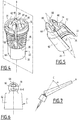
figure 4 is a perspective view of the first part of the joint mechanism of the device shown infigures 2 and 3 ; -
figures 5 and 6 are respectively perspective and side views of the second part of the joint mechanism shown infigures 2 and 3 ; -
figure 7 is a diagrammatical views of the device comprising a joint mechanism according to an embodiment, after modification of the angle between the first part and the second part. - A
first device 10 according to the invention is shown inFigure 1 . - The
device 10 is intended to condition a cosmetic product and to apply the cosmetic product on a body surface of a user, for example on the skin, or a keratin fiber of a user. - The cosmetic product is advantageously a makeup or care product such as an eye-liner, a mascara, a gloss or a lipstick. Preferably, the cosmetic product has a fluid form.
- The
device 10 shown infigures 1, 2 and 3 comprises agripping member 14, arod carrier 16 carrying anapplicator 18 and ajoint mechanism 12 connecting thegripping member 14 to therod carrier 16. Thedevice 10 further comprises areceptacle 20, wherein therod carrier 16 and theapplicator 18 are intended to be introduced. - The
joint mechanism 12 comprises afirst part 22 mobile jointly in rotation with thegripping member 14 and asecond part 24 mounted mobile jointly in rotation with therod carrier 16, with thefirst part 22 and thesecond part 24 being mounted mobile in rotation in relation to one another about an axis A-A'. - The
first part 22, in particular shown infigure 4 , comprises anouter skirt 26, arib 28 mounted in the center of theskirt 26, at least one protrudingjoint pin 30 and anupper portion 32. - The
outer skirt 26 extends between afree edge 34 and anupper edge 36 about a main axis B. Theskirt 26 moves away from the axis B between theupper edge 36 and thefree edge 34. Alternatively, theskirt 26 is substantially a cylinder about the axis B. - The
skirt 26 is hollow and delimits aninner surface 37. - The
skirt 26 definesnotches 38. Thesenotches 38 exit on itsfree edge 34. Theskirt 26 comprises for example fournotches 38. Thenotches 38 of theskirt 26 define inbetween at least onedeformable tab 40. Thedeformable tab 40 is able to be moved away from and/or brought closer to the axis B. - The
rib 28 protrudes outside of theouter skirt 26 beyond thefree edge 34. - The
rib 28 here has two ends 42 linked to theinner surface 37 of theskirt 26 and located on either side of theskirt 26. The two ends 42 are connected by a protrudingportion 44, for example substantially in the shape of an arc or of a parabola. - The
rib 28 extends substantially along a median plane P of theskirt 26 comprising the axis B. - In the embodiment shown, the
rib 28 comprises an inner recess and can be deformed in the event of pressure exerted on its protrudingportion 44. The recess facilitates the deformation of the rib according to the material used. Alternatively, the rib can be full while still remaining deformable. In particular, the deformation varies according to the resulting thickness between the protruding portion and the inner recess of therib 28. - The
rib 28 defines on the protruding portion at least oneindexing relief 46, of which the function shall be described hereinbelow. Therelief 46 comprises at least one tooth. - The
joint pin 30 extends to the axis B from theinner surface 37 of theskirt 26. Thejoint pin 30 is carried by adeformable tab 40. It has a general cylindrical shape with an axis substantially perpendicular to the tangent to theinner surface 37 of theskirt 26 on thepin 30. - The
joint pin 30 does not pass through the plane P wherein therib 28 extends. - Each
joint pin 30 extends parallel to the axis A-A'. The joint pins 30 are transversally offset in relation to the axis A-A'. - The
first part 22 advantageously comprises twoopposite pins 30. The joint pins 30 are located on either side of the plane P along which extends therib 28. Thepins 30 are here located substantially at an equal distance from the two ends 42 of therib 28. - The
pins 30 are each carried by a differentdeformable tab 40. - The
upper portion 32 extends from theupper edge 36 of theskirt 26. It has the general shape of a cylinder, of axis confounded with the axis B, comprising aslot 48. Theslot 48 in particular guides the introduction of the grippingmember 14. Theslot 48 provides an indexing of the gripping member during assembly. - The
second part 24, shown in particular infigures 5 and 6 , comprises, from bottom to top infigure 5 , abracket 60 for receiving therib 28, and aband 62 for mounting the rod carrier. It defines at least one path for guiding 64 thejoint pin 30. - The
bracket 60 delimits acentral slot 66, having a complementary shape of therib 28 of thefirst part 22. Thecentral slot 66 extends along a plane P'. - The
bracket 60 here comprises twolateral flanges 68 separated by a space forming theslot 66. Thebracket 60 substantially has the shape of a ball. The plane of theslot 66 passes through the center of the ball. - The
central slot 66 has a bottom. The bottom comprises at least onenotch 70 for cooperating with theindexing relief 46. Eachnotch 70 is complementary with arelief 46 of therib 28. - The
band 62 extends between afree edge 72 and an edge linked 74 to thebracket 60, intended to be placed opposite the free edge of theskirt 26. - The
band 62 defines aninner cavity 76 for insertion of the rod carrier, delimited by aninner surface 77. Theband 62 has for example substantially the shape of a hollow cylinder closed at its edge linked 74 to thebracket 60, by the intermediary of a support plate of thebracket 60. - The
bracket 60 protrudes with respect to theband 62 on the support plate, opposite theinner cavity 76. - In reference to
figure 6 , the path for guiding 64 is arranged in thebracket 60 in thelateral flange 68 of the bracket. - The
second part 24 has the same number of paths for guiding 64 as thefirst part 22 has pins 30. - The path for guiding 64 defines
end abutments 78, which can be seen infigure 6 , able to limit the course of thepin 30 that it receives. - The path for guiding 64 is here a curved hole centered around the axis A-A', having a constant width that corresponds to the width of the
pin 30. The axis A-A' is for example closer to theband 62 than the path for guiding 64. - The angular extent of the path for guiding 64 about the axis A-A' corresponds substantially to the desired course of the
first part 22 with respect to thesecond part 24 in rotation about the axis A-A'. - The maximum angle α between the
first part 22 and thesecond part 24, at the end of travel of thepin 30 in the path for guiding 64 shown infigure 7 , is for example less than 40°, and is in particular between 15° and 40°, and is particularly equal to 35°. - The shape of the path for guiding 64 is complementary with the trajectory swept by the
pin 30 in thebracket 60 during a displacement of thefirst part 22 with respect to thesecond part 24. - This shape is here substantially a shape of a bean or an oblong hole with a trajectory coaxial to the axis A-A'.
- The
joint mechanism 12 is formed from the assembly of thefirst part 22 and of thesecond part 24. - The
rib 28 of thefirst part 22 is received in theslot 66 of thebracket 60 of thesecond part 24. The plane P of therib 28 and the plane P' of thecentral slot 66 for receiving are then substantially confounded. Eachpin 30 is received in a corresponding path for guiding 64. - The
skirt 26 of thefirst part 22 is then arranged around thebracket 60 of thesecond part 24. Thebracket 60 protrudes at least partially outside of theskirt 26, for example on aportion 80 of thebracket 60 in contact with theband 62. As such, the shape of thebracket 60 can be seen, which improves the aesthetic appearance and the clearance in rotation of thefirst part 22 with respect to thesecond part 24. - The
first part 22 and thesecond part 24 are mobile in rotation with respect to one another about the axis A-A'. - In the example shown in the figure, the
joint mechanism 12 comprises anangular indexing arrangement 82 of the rib with respect to the bracket, which can be seen infigure 3 . Theangular indexing arrangement 82 comprises thereliefs 46 of therib 28 and thenotches 70 arranged at the bottom of thebracket 60 that cooperates with thereliefs 46. - The
angular indexing arrangement 82 comprises for example at least three indexing positions of thefirst part 22 with respect to thesecond part 24, with each position being characterized by the presence of aparticular relief 46 in a givennotch 70. - The passing from one position of the
angular indexing arrangement 82 to another is carried out by a rotation of therib 28 in thebracket 60 and by displacement of thepin 30 in the path for guiding 64. During the passing from one position to another, the inner recess facilitates a deformation of therib 28 in order to allow for the passage of therelief 46. - Two of the three indexing positions advantageously correspond to the configurations wherein each
pin 30 is located on anend abutment 78 of the corresponding path for guiding 64. The third position corresponds to a median position of thepin 30 within the path for guiding 64. - The
angular indexing arrangement 82 maintains therib 28 in a position within thebracket 60. In order to pass from one indexing position to another, a user is able to manually exert a force of displacement that makes it possible to modify the angular position of therib 28 within thebracket 60. Theangular indexing arrangement 82 has however an anti-return function when thepin 30 is located on oneend abutment 78 of the corresponding path for guiding 64. - The gripping
member 14 is intended to be gripped by a user. The grippingmember 14 is for example an elongated cap along a main axis confounded with the axis B. In an embodiment, a portion of the surface of the grippingmember 14 is anti-skid. - The gripping
member 14 is mounted integral in rotation with thefirst part 22. The gripping member is, for example, fixed by gluing. - The gripping
member 14 has a cavity receiving thefirst part 22. It covers theupper portion 32 and, at least partially, theskirt 26 of thefirst part 22. - When the
skirt 26 is provided withnotches 38, defining at least onedeformable tab 40, the cavity of the grippingmember 14 has a shape complementary with the outer surface of theupper portion 32 and with at least one portion of theskirt 26, when the deformable tab ortabs 40 are brought closer to the axis B. - In reference to
figure 2 , therod carrier 16 comprises afastening portion 84 and a bearingmember 86. - The
rod carrier 16 is integral in rotation with thesecond part 24. Thefastening portion 84 is of complementary shape with theinner cavity 76 defined by theband 62. - The
fastening portion 84 has aninner surface 90 forming for example a thread pitch that can be engaged on the receptacle. - Here, the
rod carrier 16 provides the closing of the receptacle. Alternatively, according to the configuration of therod carrier 16, the closing function of thereceptacle 20 can be carried out directly by theband 62, then having a threading that can be engaged with thereceptacle 20. - The carrying
member 86 extends from thefastening portion 84. It has afree end 92 from which theapplicator 18 extends. Theapplicator 18 extends along a main axis C. - The
applicator 18 is partially inserted into the carryingmember 86. It comprises an outeractive portion 98 that makes it possible to apply the product. Alternatively, theapplicator 18 is fully inserted into the carryingmember 86 of therod carrier 16 and a mechanism makes it possible to exit a portion of theapplicator 18 of therod carrier 16, for example a push mechanism. - The
applicator 18 is for example an eye-liner tip, a mascara tip or a foam tip for gloss. - The gripping
member 14 and therod carrier 16 carrying theapplicator 18 are mounted on either side of thejoint mechanism 12. The grippingmember 14 and therod carrier 16 are mounted mobile in rotation about the axis A-A' by the intermediary of thejoint mechanism 12. - In this example, there is a position of the
angular indexing arrangement 82 such as the axes C and B are confounded. In the event where there are three possible positions of angular indexing arrangement, two of which correspond to endabutments 78 of the path for guiding 64, the position for which the axes C and B are confounded is the median position. - The
receptacle 20 comprises abottle 100 and a squeezingdevice 102. - The
bottle 100 defines avolume 104 for receiving cosmetic product, which opens via aneck 112. - The
neck 112 comprises a complementary thread pitch with respect to the thread pitch of therod carrier 16. Thereceptacle 20 can be made integral with therod carrier 16 in a removable manner. - The
rod carrier 16 is as such able to pass from a storage configuration, by being inserted in thereceptacle 20, to a configuration for applying cosmetic product, by being arranged outside of thereceptacle 20. - The squeezing
device 102 is fixed to thebottle 100 on theneck 112. - During the removal of the
rod carrier 16, theapplicator 18 is substantially in contact with the squeezingdevice 102 so as to remove the excess product that it is carrying. - A method for mounting a
joint mechanism 12 according to the invention will now be described. - The
first part 22 having arib 28 and thesecond part 24 carrying abracket 60 are provided. Thefirst part 22 comprises at least one protrudingjoint pin 30 and thesecond part 24 defines a path for guiding 64 thepin 30. - The
first part 22 and thesecond part 24 are aligned. Therib 28 is then inserted into thebracket 60. - During the inserting of the
rib 28 into thebracket 60, thepin 30 enters into the path for guiding 64. Thepin 30 and the path for guiding 64 are off-centered with respect to the axis A-A'. Thepin 30 is mobile along the path for guiding 64. - The
deformable tab 40 moves away by elastic deformation from the axis B from theskirt 26 for the insertion of thepin 30 into the path for guiding 64, then returns to its configuration once inserted. Alternatively, thedeformable tab 40 is initially spaced from the axis of theskirt 26 in order to allow for the insertion of thepin 30 into the path for guiding 64, and is tightened once thepin 30 is inserted in the path for guiding 64 so that thepin 30 is maintained in the path for guiding 64. - The gripping
member 14 is then mounted around thefirst part 22, by leaving therib 28 still accessible. The grippingmember 14 maintains thepin 30 within the path for guiding 64, by preventing the radial deformation of thetab 40. - The
mechanism 12 is then functional. - A method of applying cosmetic product with an
application device 10 of cosmetic product implementing ajoint mechanism 12, such as described hereinabove, will now be described. - Initially, an
application device 10 such as described hereinabove is provided. The main axis of the grippingmember 14 is substantially confounded with the axis B of the skirt. The axis of theapplicator 18 and the axis of the gripping member B are in a first relative angular position about the pivot axis, by being aligned in relation to one another. - The aesthetic appearance of the
application device 10 is very satisfying. - The user removes the unit formed by the gripping
member 14, thejoint mechanism 12, therod carrier 16 and theapplicator 18 of thereceptacle 20. Theapplicator 18 passes through the squeezingdevice 102, causing the squeezing of the product. - Then, the user pivots the gripping
member 14 with respect to therod carrier 16 by surmounting the retaining force supplied by the indexing arrangement. Thepin 30 is displaced in the path for guiding 64 in order to guide the pivoting. The angle α between therod carrier 16 and the grippingmember 14 is as such modified. The grippingmember 14 and therod carrier 16 are then in a second relative angular position about the pivot axis, wherein the axis C of theapplicator 18 and the axis B of the grippingmember 14 are inclined by a non-zero angle α. - The user applies the cosmetic product on the provided body surface using the applicator, which is made simple thanks to the relative inclination between the axes B and C.
- In an alternative (not shown), the
second part 24 comprises at least onepin 30 and thefirst part 22 comprises at least one path for guiding 64. Thepin 30 is for example carried by thebracket 60 and the path for guiding 64 is defined in theouter skirt 26 on adeformed tab 40.
the pin being inserted into the path for guiding during the inserting of the rib into the bracket, with the pin and the path for guiding being off-centered with respect to the axis.
Claims (15)
- Joint mechanism (12) of an application device (10) of a cosmetic product, comprising a first part (22) having a rib (28) and a second part (24) carrying a bracket (60) receiving the rib (28), said first part (22) being mobile in rotation with respect to said second part (24) about an axis (A-A'),
wherein one among the first part (22) and the second part (24) comprises at least one protruding pin (30), and in that the other among the first part (22) and the second part (24) defines a path for guiding (64) the pin (30), the pin (30) being inserted into the path for guiding (64), characterised in that the pin (30) and the path for guiding (64) are off-centered with respect to the axis (A-A'). - Mechanism (12) according to claim 1, wherein the path for guiding (64) defines end abutments (78) able to limit the course of the pin (30) in rotation about the axis (A-A').
- Mechanism (12) according to any of the preceding claims, wherein one among the first part (22) and the second part (24) comprises two opposite pins (30), located on either side of a plane of displacement of the rib (28) in the bracket (60), the other among the first part (22) and the second part (24) defining two opposite paths for guiding (64) each receiving one of said pins (30).
- Mechanism (12) according to any of the preceding claims, wherein the path for guiding (64) has the shape of a curved oblong hole about the axis (A-A'), the axis (A-A') being located away from the path for guiding (64).
- Mechanism (12) according to any of the preceding claims, comprising an annular indexing arrangement (82) of the rib (28) with respect to the bracket (60) in at least one angular position.
- Mechanism (12) according to claim 5, wherein the bracket (60) defines a central slot (66) for receiving the rib (28) having a bottom, with the annular indexing arrangement (82) comprising at least one notch (70) arranged in the bottom of the slot (66), able to cooperate with complementary reliefs (46) of the rib (28).
- Mechanism (12) according to any of the preceding claims, wherein the first part (22) has an outer skirt (26) arranged around the bracket (60) when the pin (30) is received in the path for guiding (64), with the bracket (60) protruding at least partially outside of the skirt (26).
- Mechanism (12) according to claim 7, wherein the skirt (26) defines at least one deformable tab (40) carrying one of the pin (30) and the path for guiding (64), with the tab (40) being radially deformable with respect to an axis of the skirt (26) in order to allow for the insertion of the pin (30) into the path for guiding (64).
- Mechanism (12) according to any of the preceding claims, wherein the second part (24) comprises a band (62) defining an inner cavity (76) for receiving a receptacle (20), with the bracket (60) protruding with respect to the band (62) opposite the inner cavity (76).
- Mechanism (12) according to any of the preceding claims, wherein the first part (22) comprises the or each pin (30), with the or each path for guiding (64) being defined in the bracket (60).
- Cosmetic product application device (10), comprising:- a rod carrier (16) and an applicator (18) carried by the rod carrier (16);- a gripping member (14);- a joint mechanism (12) according to any of the preceding claims, with the first part (22) being integral in rotation with the gripping member (14), with the second part (24) being integral in rotation with the rod carrier (16), the rod carrier (16) being mounted mobile in rotation with respect to the gripping member (14) about the axis (A-A') by the intermediary of the joint mechanism (12).
- Device (10) according to claim 11, device comprising a receptacle (20) containing cosmetic product, with the rod carrier (16) able to switch from a storage configuration inserted in the receptacle (20) to a configuration for applying cosmetic product, arranged outside of the receptacle (20).
- Device (10) according to claim 11 or 12, wherein the gripping member (14) is formed by an elongated cap mounted around the first part (22).
- Method for applying cosmetic product on the surface of the body of a user, including the following steps:- supplying of a device (10) according to any of claims 11 to 13 with the rod carrier (16) and the gripping member (14) occupying a first relative angular position about the axis (A-A');- pivoting of the gripping member (14) with respect to the rod carrier (16), to displace them in a second relative angular position about the axis (A-A'), with the pin (30) circulating in the path for guiding (64) in order to guide the pivoting;- application of the cosmetic product on the body surface.
- Method for mounting a joint mechanism (12) of an application device (10) of cosmetic product according to any of claims 11 to 13, including the following steps:- suppling of a first part (22) having a rib (28) and a second part (24) carrying a bracket (60),- inserting of the rib (28) into the bracket (60), with the rib (28) being mounted mobile in rotation about a pivot axis (A-A'),wherein one among the first part (22) and the second part (24) comprises at least one protruding pin (30), and the other among the first part (22) and the second part (24) defines a path for guiding (64),
the pin (30) being inserted into the path for guiding (64) during the inserting of the rib (28) into the bracket (60), with the pin (30) and the path for guiding (64) being off-centered with respect to the axis (A-A').
Applications Claiming Priority (2)
| Application Number | Priority Date | Filing Date | Title |
|---|---|---|---|
| FR1500790A FR3034968B1 (en) | 2015-04-15 | 2015-04-15 | JOINT MECHANISM OF A COSMETIC PRODUCT APPLICATION DEVICE, DEVICE, METHOD OF APPLICATION, AND METHOD OF MANUFACTURING THE SAME |
| PCT/EP2016/058415 WO2016166327A1 (en) | 2015-04-15 | 2016-04-15 | Joint mechanism of an application device of a cosmetic product, associated device, application method and manufacturing method |
Publications (2)
| Publication Number | Publication Date |
|---|---|
| EP3282885A1 EP3282885A1 (en) | 2018-02-21 |
| EP3282885B1 true EP3282885B1 (en) | 2019-05-22 |
Family
ID=53200069
Family Applications (1)
| Application Number | Title | Priority Date | Filing Date |
|---|---|---|---|
| EP16716601.6A Active EP3282885B1 (en) | 2015-04-15 | 2016-04-15 | Joint mechanism of an application device of a cosmetic product, associated device, application method and manufacturing method |
Country Status (8)
| Country | Link |
|---|---|
| US (1) | US11412831B2 (en) |
| EP (1) | EP3282885B1 (en) |
| JP (1) | JP6605619B2 (en) |
| KR (1) | KR101943531B1 (en) |
| CN (1) | CN107529870B (en) |
| ES (1) | ES2742806T3 (en) |
| FR (1) | FR3034968B1 (en) |
| WO (1) | WO2016166327A1 (en) |
Families Citing this family (6)
| Publication number | Priority date | Publication date | Assignee | Title |
|---|---|---|---|---|
| FR3031283B1 (en) * | 2015-01-05 | 2017-07-28 | Oreal | COSMETIC APPLICATOR |
| FR3051642B1 (en) * | 2016-05-27 | 2020-05-15 | L'oreal | ARTICULATED COSMETIC APPLICATOR AND PACKAGING AND APPLICATION ASSEMBLY |
| FR3055196B1 (en) * | 2016-08-25 | 2022-07-01 | Oreal | ARTICULATED COSMETIC PRODUCT APPLICATOR AND ASSOCIATED PACKAGING AND APPLICATION ASSEMBLY |
| KR200491956Y1 (en) * | 2018-11-26 | 2020-07-07 | 주식회사 엘지생활건강 | Cosmetic vessel |
| USD861245S1 (en) | 2019-03-29 | 2019-09-24 | Rea.Deeming Beauty, Inc. | Cosmetic tool with rolling applicator |
| JP7817087B2 (en) * | 2022-06-07 | 2026-02-18 | 花王株式会社 | Wearing equipment |
Citations (1)
| Publication number | Priority date | Publication date | Assignee | Title |
|---|---|---|---|---|
| EP1994852A1 (en) * | 2007-05-22 | 2008-11-26 | L'oreal | Make-up box |
Family Cites Families (44)
| Publication number | Priority date | Publication date | Assignee | Title |
|---|---|---|---|---|
| US245659A (en) * | 1881-08-16 | Cheist eenner | ||
| US2749567A (en) * | 1951-08-07 | 1956-06-12 | Krueger Max | Adjustable tooth brush |
| US3433510A (en) * | 1966-09-26 | 1969-03-18 | Flambeau Plastics Corp | Swivel joint structure |
| JPS5116205Y1 (en) | 1970-06-16 | 1976-04-28 | ||
| US4033007A (en) * | 1975-04-01 | 1977-07-05 | Joseph Hadary | Toothbrush |
| US4370989A (en) * | 1977-08-11 | 1983-02-01 | Taylor Charles H | Applicator for liquid cosmetics |
| DE2739694A1 (en) * | 1977-09-02 | 1979-03-08 | Hans Eugen Ihne | Applicator for hair treatment products such as tints - consists of forked handle for brush and holder on pivot pins |
| US4165755A (en) * | 1977-09-26 | 1979-08-28 | Cassai Gino H | Adjustable mascara wand |
| US4396028A (en) * | 1982-10-22 | 1983-08-02 | Waggoner Edward S | Suntan lotion applicator device |
| US4738252A (en) * | 1987-09-18 | 1988-04-19 | Friddle's Orthopedic Appliances, Inc. | Mechanical joint construction |
| US5240265A (en) * | 1992-10-23 | 1993-08-31 | Huang Ming Tai | Joint for mounting a backrest support on a stroller frame |
| FR2738127B1 (en) * | 1995-08-30 | 1998-03-27 | Oreal | MASCARA APPLICATOR |
| FR2753056B1 (en) * | 1996-09-10 | 1998-10-16 | Oreal | MAKEUP OR CARE PRODUCT APPLICATOR |
| DE19706198A1 (en) * | 1997-02-18 | 1998-08-20 | Geka Brush Georg Karl Gmbh | Interdental cleaning device |
| US6203511B1 (en) * | 1998-06-25 | 2001-03-20 | Becker Orthopedic Appliance Company, Inc. | Orthotic joint and method |
| US6238124B1 (en) * | 1999-01-13 | 2001-05-29 | Werner O. Merlo | Locking joint mechanism |
| US6390483B1 (en) * | 2000-07-19 | 2002-05-21 | Hao Yih Trading Co., Ltd. | Folding device for scooter |
| ITMI20012245A1 (en) * | 2001-10-25 | 2003-04-25 | Ponzini Spa | DEVICE OF SUPPORTS FOR INTERDENTAL BRUSH AND SIMILAR ORAL HYGIENE TOOLS |
| US6760949B2 (en) * | 2002-09-04 | 2004-07-13 | Bruce Kaminstein | Rotating dish brush |
| US7487784B2 (en) * | 2002-06-07 | 2009-02-10 | L'oreal | Applicator including a stem connected to a handle member via a hinge |
| CN1274260C (en) * | 2002-06-07 | 2006-09-13 | 奥里尔股份有限公司 | Coating device with rod and handle part connected by hinge and coating material |
| US7172357B2 (en) * | 2002-06-07 | 2007-02-06 | L'oreal | Applicator comprising a sloping applicator element and a stem connected via a hinge to a handle member |
| FR2851435B1 (en) * | 2003-02-24 | 2006-07-14 | Oreal | DEVICE FOR PACKAGING AND APPLYING A COSMETIC PRODUCT. |
| US7156107B2 (en) * | 2003-06-17 | 2007-01-02 | Welter's Co., Ltd. | Teeth cleaning brush structure |
| US7032941B2 (en) * | 2003-08-06 | 2006-04-25 | Heneveld William R | Tool including adjustable handle |
| US7429141B2 (en) * | 2004-03-02 | 2008-09-30 | L'oreal | Applicator for makeup or beauty care products |
| ITMO20070215A1 (en) * | 2007-06-22 | 2008-12-23 | Nuova F Lli Dondi S R L | TOOL TO CLEAN SURFACES |
| DE102009013233A1 (en) * | 2009-03-17 | 2010-09-23 | Oekametall Oehlhorn Gmbh & Co. Kg | Applicator for applying a cosmetic and / or pharmaceutical composition, in particular mascara |
| US8701236B2 (en) * | 2009-09-21 | 2014-04-22 | Sherman Pegross | Electric toothbrush |
| US8448281B2 (en) * | 2009-10-08 | 2013-05-28 | Dyson Technology Limited | Domestic appliance |
| DE102009057026A1 (en) | 2009-12-04 | 2011-06-09 | Geka Gmbh | Cosmetic applicator, in particular Mascaraapplikator and a cosmetic product |
| KR101228255B1 (en) * | 2010-03-24 | 2013-01-30 | 홍정욱 | A mascara with adjustable angle of the brush pillar |
| CN102273806B (en) | 2010-06-11 | 2013-06-12 | 苏州洽兴塑胶有限公司 | Bendable eyelash brush |
| DE202010010860U1 (en) * | 2010-07-30 | 2011-11-02 | Geka Gmbh | Applicator and cosmetic unit comprising the applicator |
| FR2976166B1 (en) | 2011-06-08 | 2013-07-05 | Oreal | EYE-LINER APPLICATOR |
| US20130051894A1 (en) * | 2011-08-24 | 2013-02-28 | Hct Asia Ltd | Adjustable cosmetics applicator |
| JP5279886B2 (en) * | 2011-12-06 | 2013-09-04 | 株式会社 資生堂 | Mascara applicator |
| JP2014532486A (en) | 2011-12-12 | 2014-12-08 | クワンチョウ コンプレイセント インダストリアル カンパニー リミテッド | Post-feed dispenser |
| FR2987244B1 (en) * | 2012-02-29 | 2015-09-04 | Oreal | APPLICATOR COMPRISING A ROD CONNECTED BY AN ARTICULATION TO AN APPLICATION ELEMENT |
| KR101415780B1 (en) * | 2012-07-13 | 2014-07-08 | 김태연 | adjustable applicator |
| US20150164210A1 (en) * | 2013-12-12 | 2015-06-18 | Jia Hsing Enterprise Co., Ltd. | Eyelash Brush |
| FR3017780B1 (en) * | 2014-02-21 | 2016-02-19 | Oreal | ARTICULATED APPLICATOR WITH FLEXIBLE ROD |
| DE202014102873U1 (en) * | 2014-06-24 | 2014-07-03 | Geka Gmbh | Applicator with slotted tube and notches |
| US9469499B1 (en) * | 2015-12-14 | 2016-10-18 | Huei-Mei Chen | Retractable cable combined with smartphone/tablet holder |
-
2015
- 2015-04-15 FR FR1500790A patent/FR3034968B1/en not_active Expired - Fee Related
-
2016
- 2016-04-15 EP EP16716601.6A patent/EP3282885B1/en active Active
- 2016-04-15 WO PCT/EP2016/058415 patent/WO2016166327A1/en not_active Ceased
- 2016-04-15 US US15/565,520 patent/US11412831B2/en active Active
- 2016-04-15 KR KR1020177027398A patent/KR101943531B1/en active Active
- 2016-04-15 CN CN201680021811.7A patent/CN107529870B/en active Active
- 2016-04-15 JP JP2017553963A patent/JP6605619B2/en active Active
- 2016-04-15 ES ES16716601T patent/ES2742806T3/en active Active
Patent Citations (1)
| Publication number | Priority date | Publication date | Assignee | Title |
|---|---|---|---|---|
| EP1994852A1 (en) * | 2007-05-22 | 2008-11-26 | L'oreal | Make-up box |
Also Published As
| Publication number | Publication date |
|---|---|
| JP6605619B2 (en) | 2019-11-13 |
| CN107529870A (en) | 2018-01-02 |
| KR101943531B1 (en) | 2019-04-17 |
| US20180070701A1 (en) | 2018-03-15 |
| EP3282885A1 (en) | 2018-02-21 |
| FR3034968B1 (en) | 2019-06-14 |
| JP2018514267A (en) | 2018-06-07 |
| ES2742806T3 (en) | 2020-02-17 |
| CN107529870B (en) | 2020-10-23 |
| US11412831B2 (en) | 2022-08-16 |
| KR20170125368A (en) | 2017-11-14 |
| FR3034968A1 (en) | 2016-10-21 |
| WO2016166327A1 (en) | 2016-10-20 |
Similar Documents
| Publication | Publication Date | Title |
|---|---|---|
| US11412831B2 (en) | Joint mechanism of an application device of a cosmetic product, associated device, application method and manufacturing method | |
| US9668564B2 (en) | Cosmetic product applicator, device and associated method | |
| US20120121313A1 (en) | Massage device, in particular for the scalp | |
| EP3384803B1 (en) | Applicator for applying a cosmetic product | |
| EP2891427A1 (en) | Tube-type cosmetic container having double discharge means | |
| CN104582527A (en) | Applicators for fluid products such as cosmetics | |
| WO2016177827A1 (en) | Applicator for applying a cosmetic product | |
| US10736395B2 (en) | Applicator-equipped aerosol container | |
| EP3570701B1 (en) | Hair applicator | |
| EP3675686B1 (en) | Stem with bayonet closure and device equipped therewith | |
| EP3197314B1 (en) | Applicator for applying a cosmetic or care product | |
| EP2403375B1 (en) | Device for supporting at least one cosmetic article and associated method of use | |
| US20150351514A1 (en) | Device for Applying a Cosmetic Composition | |
| EP3462979B1 (en) | Hinged applicator for a cosmetic product and associated packaging and application assembly | |
| CN109688867B (en) | Hinged applicator for cosmetic products and related packaging and application assembly | |
| WO2019115811A1 (en) | Dispensing head for a cosmetic product, associated device and associated application method | |
| WO2021110717A1 (en) | Assembly for a device for dispensing and applying a cosmetic product with indexing elements and associated device | |
| WO2015193070A1 (en) | Applicator device designed to apply a cosmetic product and associated application method |
Legal Events
| Date | Code | Title | Description |
|---|---|---|---|
| STAA | Information on the status of an ep patent application or granted ep patent |
Free format text: STATUS: THE INTERNATIONAL PUBLICATION HAS BEEN MADE |
|
| PUAI | Public reference made under article 153(3) epc to a published international application that has entered the european phase |
Free format text: ORIGINAL CODE: 0009012 |
|
| STAA | Information on the status of an ep patent application or granted ep patent |
Free format text: STATUS: REQUEST FOR EXAMINATION WAS MADE |
|
| 17P | Request for examination filed |
Effective date: 20171013 |
|
| AK | Designated contracting states |
Kind code of ref document: A1 Designated state(s): AL AT BE BG CH CY CZ DE DK EE ES FI FR GB GR HR HU IE IS IT LI LT LU LV MC MK MT NL NO PL PT RO RS SE SI SK SM TR |
|
| AX | Request for extension of the european patent |
Extension state: BA ME |
|
| DAV | Request for validation of the european patent (deleted) | ||
| DAX | Request for extension of the european patent (deleted) | ||
| GRAP | Despatch of communication of intention to grant a patent |
Free format text: ORIGINAL CODE: EPIDOSNIGR1 |
|
| STAA | Information on the status of an ep patent application or granted ep patent |
Free format text: STATUS: GRANT OF PATENT IS INTENDED |
|
| INTG | Intention to grant announced |
Effective date: 20181127 |
|
| GRAS | Grant fee paid |
Free format text: ORIGINAL CODE: EPIDOSNIGR3 |
|
| GRAA | (expected) grant |
Free format text: ORIGINAL CODE: 0009210 |
|
| STAA | Information on the status of an ep patent application or granted ep patent |
Free format text: STATUS: THE PATENT HAS BEEN GRANTED |
|
| AK | Designated contracting states |
Kind code of ref document: B1 Designated state(s): AL AT BE BG CH CY CZ DE DK EE ES FI FR GB GR HR HU IE IS IT LI LT LU LV MC MK MT NL NO PL PT RO RS SE SI SK SM TR |
|
| REG | Reference to a national code |
Ref country code: GB Ref legal event code: FG4D |
|
| REG | Reference to a national code |
Ref country code: CH Ref legal event code: EP |
|
| REG | Reference to a national code |
Ref country code: IE Ref legal event code: FG4D |
|
| REG | Reference to a national code |
Ref country code: DE Ref legal event code: R096 Ref document number: 602016014293 Country of ref document: DE |
|
| REG | Reference to a national code |
Ref country code: AT Ref legal event code: REF Ref document number: 1135021 Country of ref document: AT Kind code of ref document: T Effective date: 20190615 |
|
| REG | Reference to a national code |
Ref country code: NL Ref legal event code: MP Effective date: 20190522 |
|
| REG | Reference to a national code |
Ref country code: LT Ref legal event code: MG4D |
|
| PG25 | Lapsed in a contracting state [announced via postgrant information from national office to epo] |
Ref country code: PT Free format text: LAPSE BECAUSE OF FAILURE TO SUBMIT A TRANSLATION OF THE DESCRIPTION OR TO PAY THE FEE WITHIN THE PRESCRIBED TIME-LIMIT Effective date: 20190922 Ref country code: AL Free format text: LAPSE BECAUSE OF FAILURE TO SUBMIT A TRANSLATION OF THE DESCRIPTION OR TO PAY THE FEE WITHIN THE PRESCRIBED TIME-LIMIT Effective date: 20190522 Ref country code: SE Free format text: LAPSE BECAUSE OF FAILURE TO SUBMIT A TRANSLATION OF THE DESCRIPTION OR TO PAY THE FEE WITHIN THE PRESCRIBED TIME-LIMIT Effective date: 20190522 Ref country code: NL Free format text: LAPSE BECAUSE OF FAILURE TO SUBMIT A TRANSLATION OF THE DESCRIPTION OR TO PAY THE FEE WITHIN THE PRESCRIBED TIME-LIMIT Effective date: 20190522 Ref country code: LT Free format text: LAPSE BECAUSE OF FAILURE TO SUBMIT A TRANSLATION OF THE DESCRIPTION OR TO PAY THE FEE WITHIN THE PRESCRIBED TIME-LIMIT Effective date: 20190522 Ref country code: HR Free format text: LAPSE BECAUSE OF FAILURE TO SUBMIT A TRANSLATION OF THE DESCRIPTION OR TO PAY THE FEE WITHIN THE PRESCRIBED TIME-LIMIT Effective date: 20190522 Ref country code: NO Free format text: LAPSE BECAUSE OF FAILURE TO SUBMIT A TRANSLATION OF THE DESCRIPTION OR TO PAY THE FEE WITHIN THE PRESCRIBED TIME-LIMIT Effective date: 20190822 Ref country code: FI Free format text: LAPSE BECAUSE OF FAILURE TO SUBMIT A TRANSLATION OF THE DESCRIPTION OR TO PAY THE FEE WITHIN THE PRESCRIBED TIME-LIMIT Effective date: 20190522 |
|
| PG25 | Lapsed in a contracting state [announced via postgrant information from national office to epo] |
Ref country code: RS Free format text: LAPSE BECAUSE OF FAILURE TO SUBMIT A TRANSLATION OF THE DESCRIPTION OR TO PAY THE FEE WITHIN THE PRESCRIBED TIME-LIMIT Effective date: 20190522 Ref country code: BG Free format text: LAPSE BECAUSE OF FAILURE TO SUBMIT A TRANSLATION OF THE DESCRIPTION OR TO PAY THE FEE WITHIN THE PRESCRIBED TIME-LIMIT Effective date: 20190822 Ref country code: GR Free format text: LAPSE BECAUSE OF FAILURE TO SUBMIT A TRANSLATION OF THE DESCRIPTION OR TO PAY THE FEE WITHIN THE PRESCRIBED TIME-LIMIT Effective date: 20190823 Ref country code: LV Free format text: LAPSE BECAUSE OF FAILURE TO SUBMIT A TRANSLATION OF THE DESCRIPTION OR TO PAY THE FEE WITHIN THE PRESCRIBED TIME-LIMIT Effective date: 20190522 |
|
| REG | Reference to a national code |
Ref country code: AT Ref legal event code: MK05 Ref document number: 1135021 Country of ref document: AT Kind code of ref document: T Effective date: 20190522 |
|
| PG25 | Lapsed in a contracting state [announced via postgrant information from national office to epo] |
Ref country code: DK Free format text: LAPSE BECAUSE OF FAILURE TO SUBMIT A TRANSLATION OF THE DESCRIPTION OR TO PAY THE FEE WITHIN THE PRESCRIBED TIME-LIMIT Effective date: 20190522 Ref country code: SK Free format text: LAPSE BECAUSE OF FAILURE TO SUBMIT A TRANSLATION OF THE DESCRIPTION OR TO PAY THE FEE WITHIN THE PRESCRIBED TIME-LIMIT Effective date: 20190522 Ref country code: RO Free format text: LAPSE BECAUSE OF FAILURE TO SUBMIT A TRANSLATION OF THE DESCRIPTION OR TO PAY THE FEE WITHIN THE PRESCRIBED TIME-LIMIT Effective date: 20190522 Ref country code: CZ Free format text: LAPSE BECAUSE OF FAILURE TO SUBMIT A TRANSLATION OF THE DESCRIPTION OR TO PAY THE FEE WITHIN THE PRESCRIBED TIME-LIMIT Effective date: 20190522 Ref country code: EE Free format text: LAPSE BECAUSE OF FAILURE TO SUBMIT A TRANSLATION OF THE DESCRIPTION OR TO PAY THE FEE WITHIN THE PRESCRIBED TIME-LIMIT Effective date: 20190522 Ref country code: AT Free format text: LAPSE BECAUSE OF FAILURE TO SUBMIT A TRANSLATION OF THE DESCRIPTION OR TO PAY THE FEE WITHIN THE PRESCRIBED TIME-LIMIT Effective date: 20190522 |
|
| REG | Reference to a national code |
Ref country code: ES Ref legal event code: FG2A Ref document number: 2742806 Country of ref document: ES Kind code of ref document: T3 Effective date: 20200217 |
|
| REG | Reference to a national code |
Ref country code: DE Ref legal event code: R097 Ref document number: 602016014293 Country of ref document: DE |
|
| PG25 | Lapsed in a contracting state [announced via postgrant information from national office to epo] |
Ref country code: SM Free format text: LAPSE BECAUSE OF FAILURE TO SUBMIT A TRANSLATION OF THE DESCRIPTION OR TO PAY THE FEE WITHIN THE PRESCRIBED TIME-LIMIT Effective date: 20190522 |
|
| PLBE | No opposition filed within time limit |
Free format text: ORIGINAL CODE: 0009261 |
|
| STAA | Information on the status of an ep patent application or granted ep patent |
Free format text: STATUS: NO OPPOSITION FILED WITHIN TIME LIMIT |
|
| PG25 | Lapsed in a contracting state [announced via postgrant information from national office to epo] |
Ref country code: TR Free format text: LAPSE BECAUSE OF FAILURE TO SUBMIT A TRANSLATION OF THE DESCRIPTION OR TO PAY THE FEE WITHIN THE PRESCRIBED TIME-LIMIT Effective date: 20190522 |
|
| 26N | No opposition filed |
Effective date: 20200225 |
|
| PG25 | Lapsed in a contracting state [announced via postgrant information from national office to epo] |
Ref country code: PL Free format text: LAPSE BECAUSE OF FAILURE TO SUBMIT A TRANSLATION OF THE DESCRIPTION OR TO PAY THE FEE WITHIN THE PRESCRIBED TIME-LIMIT Effective date: 20190522 |
|
| PG25 | Lapsed in a contracting state [announced via postgrant information from national office to epo] |
Ref country code: SI Free format text: LAPSE BECAUSE OF FAILURE TO SUBMIT A TRANSLATION OF THE DESCRIPTION OR TO PAY THE FEE WITHIN THE PRESCRIBED TIME-LIMIT Effective date: 20190522 |
|
| PG25 | Lapsed in a contracting state [announced via postgrant information from national office to epo] |
Ref country code: MC Free format text: LAPSE BECAUSE OF FAILURE TO SUBMIT A TRANSLATION OF THE DESCRIPTION OR TO PAY THE FEE WITHIN THE PRESCRIBED TIME-LIMIT Effective date: 20190522 |
|
| REG | Reference to a national code |
Ref country code: CH Ref legal event code: PL |
|
| PG25 | Lapsed in a contracting state [announced via postgrant information from national office to epo] |
Ref country code: LI Free format text: LAPSE BECAUSE OF NON-PAYMENT OF DUE FEES Effective date: 20200430 Ref country code: CH Free format text: LAPSE BECAUSE OF NON-PAYMENT OF DUE FEES Effective date: 20200430 Ref country code: LU Free format text: LAPSE BECAUSE OF NON-PAYMENT OF DUE FEES Effective date: 20200415 |
|
| REG | Reference to a national code |
Ref country code: BE Ref legal event code: MM Effective date: 20200430 |
|
| PG25 | Lapsed in a contracting state [announced via postgrant information from national office to epo] |
Ref country code: BE Free format text: LAPSE BECAUSE OF NON-PAYMENT OF DUE FEES Effective date: 20200430 |
|
| PG25 | Lapsed in a contracting state [announced via postgrant information from national office to epo] |
Ref country code: IE Free format text: LAPSE BECAUSE OF NON-PAYMENT OF DUE FEES Effective date: 20200415 |
|
| PG25 | Lapsed in a contracting state [announced via postgrant information from national office to epo] |
Ref country code: MT Free format text: LAPSE BECAUSE OF FAILURE TO SUBMIT A TRANSLATION OF THE DESCRIPTION OR TO PAY THE FEE WITHIN THE PRESCRIBED TIME-LIMIT Effective date: 20190522 Ref country code: CY Free format text: LAPSE BECAUSE OF FAILURE TO SUBMIT A TRANSLATION OF THE DESCRIPTION OR TO PAY THE FEE WITHIN THE PRESCRIBED TIME-LIMIT Effective date: 20190522 |
|
| PG25 | Lapsed in a contracting state [announced via postgrant information from national office to epo] |
Ref country code: MK Free format text: LAPSE BECAUSE OF FAILURE TO SUBMIT A TRANSLATION OF THE DESCRIPTION OR TO PAY THE FEE WITHIN THE PRESCRIBED TIME-LIMIT Effective date: 20190522 Ref country code: IS Free format text: LAPSE BECAUSE OF FAILURE TO SUBMIT A TRANSLATION OF THE DESCRIPTION OR TO PAY THE FEE WITHIN THE PRESCRIBED TIME-LIMIT Effective date: 20190922 |
|
| PGFP | Annual fee paid to national office [announced via postgrant information from national office to epo] |
Ref country code: DE Payment date: 20250305 Year of fee payment: 10 |
|
| PGFP | Annual fee paid to national office [announced via postgrant information from national office to epo] |
Ref country code: ES Payment date: 20250506 Year of fee payment: 10 |
|
| PGFP | Annual fee paid to national office [announced via postgrant information from national office to epo] |
Ref country code: GB Payment date: 20260313 Year of fee payment: 11 |
|
| PGFP | Annual fee paid to national office [announced via postgrant information from national office to epo] |
Ref country code: IT Payment date: 20260320 Year of fee payment: 11 |
|
| PGFP | Annual fee paid to national office [announced via postgrant information from national office to epo] |
Ref country code: FR Payment date: 20260309 Year of fee payment: 11 |