EP3282687A1 - Information processing device, information processing method, and information processing program - Google Patents
Information processing device, information processing method, and information processing program Download PDFInfo
- Publication number
- EP3282687A1 EP3282687A1 EP16776508.0A EP16776508A EP3282687A1 EP 3282687 A1 EP3282687 A1 EP 3282687A1 EP 16776508 A EP16776508 A EP 16776508A EP 3282687 A1 EP3282687 A1 EP 3282687A1
- Authority
- EP
- European Patent Office
- Prior art keywords
- image
- virtual
- dimensional
- unit
- full
- Prior art date
- Legal status (The legal status is an assumption and is not a legal conclusion. Google has not performed a legal analysis and makes no representation as to the accuracy of the status listed.)
- Granted
Links
Images







Classifications
-
- G—PHYSICS
- G09—EDUCATION; CRYPTOGRAPHY; DISPLAY; ADVERTISING; SEALS
- G09G—ARRANGEMENTS OR CIRCUITS FOR CONTROL OF INDICATING DEVICES USING STATIC MEANS TO PRESENT VARIABLE INFORMATION
- G09G3/00—Control arrangements or circuits, of interest only in connection with visual indicators other than cathode-ray tubes
- G09G3/001—Control arrangements or circuits, of interest only in connection with visual indicators other than cathode-ray tubes using specific devices not provided for in groups G09G3/02 - G09G3/36, e.g. using an intermediate record carrier such as a film slide; Projection systems; Display of non-alphanumerical information, solely or in combination with alphanumerical information, e.g. digital display on projected diapositive as background
- G09G3/003—Control arrangements or circuits, of interest only in connection with visual indicators other than cathode-ray tubes using specific devices not provided for in groups G09G3/02 - G09G3/36, e.g. using an intermediate record carrier such as a film slide; Projection systems; Display of non-alphanumerical information, solely or in combination with alphanumerical information, e.g. digital display on projected diapositive as background to produce spatial visual effects
-
- G—PHYSICS
- G06—COMPUTING OR CALCULATING; COUNTING
- G06T—IMAGE DATA PROCESSING OR GENERATION, IN GENERAL
- G06T15/00—Three-dimensional [3D] image rendering
- G06T15/10—Geometric effects
- G06T15/20—Perspective computation
- G06T15/205—Image-based rendering
-
- G—PHYSICS
- G06—COMPUTING OR CALCULATING; COUNTING
- G06T—IMAGE DATA PROCESSING OR GENERATION, IN GENERAL
- G06T3/00—Geometric image transformations in the plane of the image
- G06T3/08—Projecting images onto non-planar surfaces, e.g. geodetic screens
-
- G—PHYSICS
- G06—COMPUTING OR CALCULATING; COUNTING
- G06T—IMAGE DATA PROCESSING OR GENERATION, IN GENERAL
- G06T3/00—Geometric image transformations in the plane of the image
- G06T3/12—Panospheric to cylindrical image transformations
-
- G—PHYSICS
- G06—COMPUTING OR CALCULATING; COUNTING
- G06T—IMAGE DATA PROCESSING OR GENERATION, IN GENERAL
- G06T5/00—Image enhancement or restoration
- G06T5/50—Image enhancement or restoration using two or more images, e.g. averaging or subtraction
-
- G—PHYSICS
- G06—COMPUTING OR CALCULATING; COUNTING
- G06T—IMAGE DATA PROCESSING OR GENERATION, IN GENERAL
- G06T5/00—Image enhancement or restoration
- G06T5/80—Geometric correction
-
- H—ELECTRICITY
- H04—ELECTRIC COMMUNICATION TECHNIQUE
- H04N—PICTORIAL COMMUNICATION, e.g. TELEVISION
- H04N23/00—Cameras or camera modules comprising electronic image sensors; Control thereof
- H04N23/45—Cameras or camera modules comprising electronic image sensors; Control thereof for generating image signals from two or more image sensors being of different type or operating in different modes, e.g. with a CMOS sensor for moving images in combination with a charge-coupled device [CCD] for still images
-
- H—ELECTRICITY
- H04—ELECTRIC COMMUNICATION TECHNIQUE
- H04N—PICTORIAL COMMUNICATION, e.g. TELEVISION
- H04N23/00—Cameras or camera modules comprising electronic image sensors; Control thereof
- H04N23/60—Control of cameras or camera modules
- H04N23/698—Control of cameras or camera modules for achieving an enlarged field of view, e.g. panoramic image capture
-
- H—ELECTRICITY
- H04—ELECTRIC COMMUNICATION TECHNIQUE
- H04N—PICTORIAL COMMUNICATION, e.g. TELEVISION
- H04N5/00—Details of television systems
- H04N5/222—Studio circuitry; Studio devices; Studio equipment
- H04N5/262—Studio circuits, e.g. for mixing, switching-over, change of character of image, other special effects ; Cameras specially adapted for the electronic generation of special effects
- H04N5/2628—Alteration of picture size, shape, position or orientation, e.g. zooming, rotation, rolling, perspective, translation
-
- H—ELECTRICITY
- H04—ELECTRIC COMMUNICATION TECHNIQUE
- H04N—PICTORIAL COMMUNICATION, e.g. TELEVISION
- H04N5/00—Details of television systems
- H04N5/222—Studio circuitry; Studio devices; Studio equipment
- H04N5/262—Studio circuits, e.g. for mixing, switching-over, change of character of image, other special effects ; Cameras specially adapted for the electronic generation of special effects
- H04N5/272—Means for inserting a foreground image in a background image, i.e. inlay, outlay
-
- G—PHYSICS
- G06—COMPUTING OR CALCULATING; COUNTING
- G06T—IMAGE DATA PROCESSING OR GENERATION, IN GENERAL
- G06T2207/00—Indexing scheme for image analysis or image enhancement
- G06T2207/20—Special algorithmic details
- G06T2207/20212—Image combination
- G06T2207/20221—Image fusion; Image merging
-
- G—PHYSICS
- G06—COMPUTING OR CALCULATING; COUNTING
- G06T—IMAGE DATA PROCESSING OR GENERATION, IN GENERAL
- G06T2215/00—Indexing scheme for image rendering
- G06T2215/06—Curved planar reformation of 3D line structures
Definitions
- the present invention relates to an information processing apparatus, an information processing method, and an information processing program.
- a technology to paste and display a full-spherical panoramic image obtained by imaging an omnidirectional range, on an inner wall of a virtual three-dimensional sphere has been disclosed.
- an information processing apparatus includes: a pasting unit configured to paste a full-spherical panoramic image obtained by imaging an omnidirectional range, along an inner wall of a virtual three-dimensional sphere arranged in a virtual three-dimensional space; an acquiring unit configured to acquire an embedding image to be embedded in the full-spherical panoramic image; a generating unit configured to generate a planar image obtained by pasting the embedding image on a two-dimensional plane; a calculating unit configured to calculate an arrangement position for arranging the planar image closer to a center point of the virtual three-dimensional sphere than the inner wall, in such an orientation that a line-of-sight direction from the center point to the inner wall and a perpendicular line of the planar image are parallel to each other; and a display control unit configured to display a display image on a display unit, the display image being obtained by converting a state in which the full-spherical panoramic image is pasted along the
- FIG. 1 is a schematic diagram of an information processing system 10 according to an embodiment.
- the information processing system 10 includes an information processing apparatus 12, a display unit 16, and an operating unit 18.
- the information processing apparatus 12, the display unit 16, and the operating unit 18 are communicably connected to one another via a wireless or wired communication unit, such as a network.
- a short-range wireless technology a wireless communication network using a mobile communication system, the Internet, or the like is used.
- Examples of the short-range wireless technology include Bluetooth (registered trademark).
- Examples of the wireless communication network using a mobile communication system include third generation (3G) and Worldwide Interoperability for Microwave Access (WiMAX).
- the display unit 16 is a commonly used display device for displaying an image.
- a liquid crystal display, an organic electroluminescent (EL) display, or the like may be used.
- the operating unit 18 has a function to receive various operation instructions from a user.
- the operating unit 18 includes a keyboard 18A, a mouse 18B, and a user interface (UI) unit 18C.
- UI user interface
- the UI unit 18C is a device that has a touch panel function to receive input of an operation from a user and display various images. That is, the UI unit 18C has a function of a display unit.
- a computer such as a smartphone, a tablet terminal, a notebook personal computer, a desktop personal computer, or a personal data assistant (PDA)
- PDA personal data assistant
- the UI unit 18C and the information processing apparatus 12 are illustrated to be connected by wire in FIG. 1 , but may be connected wirelessly. Specifically, in the case of a wireless connection, it may be possible to provide the information processing apparatus 12 on the Internet and cause the UI unit 18C to operate the information processing apparatus 12 to perform editing over a network.
- the information processing system 10 may include other kinds of operating units rather than the keyboard 18A, the mouse 18B, and the UI unit 18C, or may further include a plurality of imaging devices 14.
- the information processing apparatus 12 is a computer that performs display and editing of material. In the embodiment, the information processing apparatus 12 controls display of an image on the display unit 16 or the UI unit 18C.
- the UI unit 18C is a computer, such as a smartphone or a tablet terminal, the functions of the information processing apparatus 12 may be implemented in the UI unit 18C.
- the information processing apparatus 12 displays a full-spherical panoramic image on the display unit 16 or the UI unit 18C.
- the full-spherical panoramic image is a panoramic image obtained by imaging a full-spherical (360-degree omnidirectional) range.
- the full-spherical panoramic image is a panoramic image obtained by obtaining an image in a solid angle of 4 ⁇ steradian and imaging a full-spherical range.
- the panoramic image is an image with an angle of view wider than an aspect ratio of a display device on which the image is finally output.
- the information processing apparatus 12 displays a full-spherical panoramic image on the display unit 16, will be described.
- the information processing apparatus 12 may display a full-spherical panoramic image on the UI unit 18C.
- the UI unit 18C has the functions of the information processing apparatus 12, the UI unit 18C displays a full-spherical panoramic image on a display unit provided on the UI unit 18C.
- the information processing apparatus 12 may store a full-spherical panoramic image in a storage unit in advance, and acquire the full-spherical panoramic image from the storage unit.
- the information processing apparatus 12 may acquire a full-spherical panoramic image from an imaging device.
- FIGS. 2 are schematic views of an exterior of the imaging device 14.
- FIG. 2A is a side view of the imaging device 14.
- FIG. 2B is a side view of the imaging device 14 on the side opposite to FIG. 2A .
- FIG. 2C is a plan view of the imaging device 14.
- the imaging device 14 has a size that allows a person to hold the imaging device 14 in one hand, for example.
- the size of the imaging device 14 is not limited to this example.
- the imaging device 14 is an imaging device that obtains a full-spherical panoramic image.
- a lens 20A is provided at a front side (at one surface side) and a lens 20B is provided at a back side (at the other surface side).
- An image is conducted through each of the wide-angle lenses with an angle of view of 180 degrees or greater, and the image is formed on each of imaging elements.
- the imaging elements include a charge coupled device (CCD) and a complementary metal-oxide semiconductor (CMOS).
- CMOS complementary metal-oxide semiconductor
- an operating unit 14C such as a shutter button, is provided at the front side of the imaging device 14.
- an imaging device described in Japanese Patent Application Laid-open No. 2014-165764 may be used, for example.
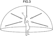
- FIG. 3 is a view illustrating an example of the usage of the imaging device 14.
- the imaging device 14 is held in the hand of a user to image objects around the user.
- the imaging elements captures images conducted through the lens 20A and the lens 20B to image the objects around the user, so that two hemispherical images are obtained and an image in the solid angle of 4 ⁇ steradian is obtained.
- FIGS. 4 are views for explaining an image captured by the imaging device 14.
- FIG. 4A illustrates a hemispherical image 42A captured by the lens 20A.
- FIG. 4B illustrates a hemispherical image 42B captured by the lens 20B.
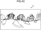
- FIG. 4C illustrates a full-spherical panoramic image 42 represented by the Mercator projection.
- the lens 20A is a fisheye lens that is one of wide angle lenses; therefore, an image obtained by the lens 20A is the curved hemispherical image 42A.
- the lens 20B is a fisheye lens that is one of wide angle lenses; therefore, an image obtained by the lens 20B is the curved hemispherical image 42B.
- the hemispherical image 42A and the hemispherical image 42B are synthesized by the imaging device 14, so that the full-spherical panoramic image 42 as illustrated in FIG. 4C is generated.
- the imaging device 14 when the imaging device 14 is connected to the information processing apparatus 12, the full-spherical panoramic image 42 obtained by the imaging device 14 is transmitted from the imaging device 14 to the information processing apparatus 12. In the embodiment, the imaging device 14 transmits the full-spherical panoramic image 42 to the information processing apparatus 12.
- the information processing apparatus 12 acquires the full-spherical panoramic image 42 from the imaging device 14.
- the information processing apparatus 12 displays the acquired full-spherical panoramic image 42 on the display unit 16, the UI unit 18C, or the like using open graphic library (OpenGL).
- OpenGL open graphic library
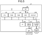
- FIG. 5 is a diagram for explaining the hardware configuration of the information processing apparatus 12.
- the information processing apparatus 12 includes a central processing unit (CPU) 30 that controls operations of the entire information processing apparatus 12, a read only memory (ROM) 32 that stores therein a program, such as initial program loader (IPL), used to drive the CPU 30, a random access memory (RAM) 34 used as a work area of the CPU 30, a hard disk (HD) 38 that stores therein various kinds of data, such as a program used for the information processing apparatus 12, and a hard disk drive (HDD) 36 that controls read and write of various kinds of data to and from the HD 38 under the control of the CPU 30.
- CPU central processing unit
- ROM read only memory
- RAM random access memory
- HD hard disk
- HDD hard disk drive
- the information processing apparatus 12 includes a media drive 507 that controls read and write (storage) of data to and from a recording medium 506, such as a flash memory, a display 508 that displays various images, an interface (I/F) 509 for communicating with the imaging device 14 and the operating unit 18 (the keyboard 18A, the mouse 18B, and the UI unit 18C), a compact disc read only memory (CD-ROM) drive 514 that controls read and write of various kinds of data to and from a CD-ROM 513 that is one example of a removable recording medium, and a bus line 510 that electrically connects the above-described components.
- a media drive 507 controls read and write (storage) of data to and from a recording medium 506, such as a flash memory
- a display 508 that displays various images
- an interface (I/F) 509 for communicating with the imaging device 14 and the operating unit 18 (the keyboard 18A, the mouse 18B, and the UI unit 18C)
- CD-ROM compact disc read only memory
- An information processing program for executing information processing performed by the information processing apparatus 12 is incorporated in the ROM 32 or any other non-volatile storage medium in advance, to be provided. Furthermore, the information processing program executed by the information processing apparatus 12 may be recorded in a computer-readable recording medium (for example, the CD-ROM 513), such as a CD-ROM, a flexible disk (FD), a compact disc recordable (CD-R), or a digital versatile disk (DVD), in a computer-installable or computer-executable file format, to be provided.
- a computer-readable recording medium for example, the CD-ROM 513
- the CD-ROM 513 such as a CD-ROM, a flexible disk (FD), a compact disc recordable (CD-R), or a digital versatile disk (DVD)
- the information processing program executed by the information processing apparatus 12 may be stored in a computer connected to a network, such as the Internet, and may be downloaded via the network, to be provided or distributed.
- the information processing program executed by the information processing apparatus 12 may be incorporated in the ROM 32 or the like in advance, to be provided.
- FIG. 6 is a schematic diagram illustrating the functional configuration of the information processing apparatus 12.
- the information processing apparatus 12 includes a control unit 52, the operating unit 18, such as the UI unit 18C, and the HD 38.
- the control unit 52 is electrically connected to the imaging device 14, the display unit 16, the operating unit 18, such as the UI unit 18C, and the HD 38.
- the control unit 52 is a computer that controls the entire information processing apparatus 12 and includes the CPU 30, the ROM 32, the RAM 34, or the like as described above.
- the control unit 52 may be constructed by a circuit or the like.
- the control unit 52 includes a connecting unit 54, an importing unit 56, a pasting unit 58, an acquiring unit 60, a generating unit 62, a calculating unit 64, and a display control unit 66.
- a part or all of the connecting unit 54, the importing unit 56, the pasting unit 58, the acquiring unit 60, the generating unit 62, the calculating unit 64, and the display control unit 66 may be implemented by causing a processor, such as a CPU, to execute a program, that is, by software, for example.
- a part or all of the connecting unit 54, the importing unit 56, the pasting unit 58, the acquiring unit 60, the generating unit 62, the calculating unit 64, and the display control unit 66 may be implemented by hardware, such as an integrated circuit (IC), or by a combination of software and hardware.
- IC integrated circuit
- the information processing program executed by the information processing apparatus 12 has a module structure including the above-described units (the connecting unit 54, the importing unit 56, the pasting unit 58, the acquiring unit 60, the generating unit 62, the calculating unit 64, and the display control unit 66).
- the CPU 30 reads and executes the information processing program from a storage medium, so that the above-described units are loaded on a main storage device and generated on the main storage device.
- the connecting unit 54 establishes connection to the imaging device 14. For example, the connecting unit 54 performs communication control to establish a connection in accordance with a communication protocol that is defined in advance together with the imaging device 14, when the imaging device 14 is connected to the information processing apparatus 12 in a wired or wireless manner. With this operation, the connecting unit 54 establishes connection to the imaging device 14.
- the importing unit 56 imports the full-spherical panoramic image 42 from the imaging device 14. It may be possible to store, in the HD 38, the full-spherical panoramic image 42 imported from the imaging device 14. In this case, the importing unit 56 may import the full-spherical panoramic image 42 from the HD 38.
- the pasting unit 58 pastes the full-spherical panoramic image 42 obtained by imaging an omnidirectional range, along an inner wall of a virtual three-dimensional sphere arranged in a virtual three-dimensional space.
- FIG. 7 is a view for explaining pasting.
- the pasting unit 58 arranges a virtual three-dimensional sphere CS in a virtual three-dimensional space.
- the virtual three-dimensional sphere CS may be a sphere whose cross section is perfectly circular, or an ellipsoid whose cross section is elliptical.
- FIG. 7 as one example, the virtual three-dimensional sphere CS that is a sphere whose cross section is perfectly circular is illustrated.
- the pasting unit 58 pastes the full-spherical panoramic image 42 on an inner wall A of the virtual three-dimensional sphere CS.
- the pasted full-spherical panoramic image 42 is referred to as a full-spherical panoramic image 40 in the description below.
- the pasting unit 58 may paste the full-spherical panoramic image 42 on the virtual three-dimensional sphere CS using a three-dimensional (3D) graphic engine, such as OpenGL.
- 3D three-dimensional
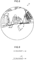
- FIG. 8 is a view illustrating an example of the full-spherical panoramic image 40.
- the full-spherical panoramic image 40 is obtained by pasting the full-spherical panoramic image 42 (see FIG. 4C ) on the inner wall A of the virtual three-dimensional sphere CS.
- FIG. 8 illustrates the full-spherical panoramic image 40 representing a state in which the inner wall A is observed in a certain line-of-sight direction from a center point P of the virtual three-dimensional sphere CS (see FIG. 7 ) .
- the acquiring unit 60 acquires an embedding image to be embedded in the full-spherical panoramic image 42.
- the embedding image may be any image to be embedded in the full-spherical panoramic image 42, and specified by an operation instruction performed on the operating unit 18 by a user.
- the embedding image is, for example, a character image representing a character.
- the generating unit 62 generates a planar image in a form such that the embedding image is pasted on a two-dimensional plane. That is, the generating unit 62 arranges a two-dimensional plane (for example, a plate-like member) in the virtual three-dimensional space, and then pastes the embedding image on the two-dimensional plane, to generate the planar image.
- a two-dimensional plane for example, a plate-like member
- FIG. 9 is a schematic view illustrating an example of an embedding image 44 and a planar image 46.
- the embedding image 44 is, for example, a character image, such as " ⁇ building".
- the generating unit 62 generates the planar image 46 obtained by pasting the embedding image 44 on a two-dimensional plane, for example.
- the acquiring unit 60 may further acquire shape information indicating a shape of the embedding image 44.
- shape information indicating a shape of the embedding image 44.
- a user operates the UI unit 18C to input an image to be embedded and shape information indicating the shape of the embedding image 44.
- the acquiring unit 60 acquires the embedding image 44 that is a target image to be embedded, and the shape information from the UI unit 18C.
- the acquiring unit 60 may further acquire size information indicating a size of the embedding image 44. The size may be input appropriately by an operation instruction performed on the UI unit 18C by the user.
- the size information is information indicating a display size of the embedding image 44.
- the generating unit 62 may generate the planar image 46 obtained by pasting the embedding image 44 on a two-dimensional plane with a shape indicated by the shape information.
- the generating unit 62 generates the planar image 46 obtained by pasting the embedding image 44 on a quadrilateral two-dimensional plane.
- the generating unit 62 may generate the planar image 46 obtained by pasting the embedding image 44 is pasted on an elliptical two-dimensional plane.
- the generating unit 62 may generate the planar image 46 with a display size indicated by the size information.
- the calculating unit 64 calculates an arrangement position for arranging the planar image 46 closer to the center point P than the inner wall A of the virtual three-dimensional sphere CS.
- the calculating unit 64 calculates the arrangement position such that the planar image 46 is arranged closer to the center point P than the inner wall A of the virtual three-dimensional sphere CS (so as to be accommodated in the virtual three-dimensional sphere CS), in such an orientation that a line-of-sight direction from the center point P of the virtual three-dimensional sphere CS to the inner wall A and a perpendicular line of the planer image 46 are parallel to each other.
- FIG. 10 is a diagram for explaining a calculation of the arrangement position.
- the calculating unit 64 arranges the planar image 46 such that a line-of-sight direction L from the center point P to the inner wall A and a perpendicular line of the planer image 46 are parallel to each other.
- the calculating unit 64 calculates how much the planar image 46 should be moved from the inner wall A to the center point P along the line-of-sight direction L to arrange the entire planar image 46 such that the entire planar image 46 is accommodated in the virtual three-dimensional sphere CS while maintaining the above-described orientation.
- the calculating unit 64 acquires a size of the planar image 46.
- the calculating unit 64 may acquire the size indicated by the size information acquired by the acquiring unit 60, or may acquire the size from the planar image 46 generated by the generating unit 62.
- the calculating unit 64 acquires a maximum length of the planar image 46 as a size d.
- the maximum length indicates a maximum length among sides and diagonal lines of the planar image 46.
- the calculating unit 64 acquires a length of a diagonal line of the planar image 46 as the size d.
- the calculating unit 64 acquires a diameter of the planar image 46 as the size d.
- the calculating unit 64 calculates an angle ⁇ between two sides corresponding to the radius r around the center point P in a triangle formed by three sides including the two sides corresponding to the radius r and one side corresponding to the size d, in accordance with Expressions (1) and (2) below.
- the calculating unit 64 calculates a movement amount h by which the planar image 46 is to be moved from the inner wall A to the center point P along the line-of-sight direction L in accordance with Expression (3) below.
- h r ⁇ 1 ⁇ cos ⁇ / 2
- the calculating unit 64 calculates, as the arrangement position of the planar image 46, a position at which the planar image 46 is moved from the inner wall A toward the center point P by the movement amount h along the line-of-sight direction L (i.e., a position of (r-h) from the center point P) while maintaining the orientation in which the perpendicular line of the planer image 46 is parallel to the line-of-sight direction L.
- the planar image 46 arranged at the calculated arrangement position (the position separated from the inner wall A by the movement amount h) is brought into a state in which the planar image 46 is accommodated in the virtual three-dimensional sphere CS, and the perpendicular line is parallel to the line-of-sight direction L. Furthermore, the planar image 46 is arranged at a position closer to the center point P than the inner wall A of the virtual three-dimensional sphere CS.
- the display control unit 66 generates a display image obtained by converting a state in which the full-spherical panoramic image 40 is pasted on the inner wall A of the virtual three-dimensional sphere CS and the planar image 46 is arranged at the arrangement position calculated by the calculating unit 64, to a two-dimensional image viewed from the center point P in the line-of-sight direction L.
- the conversion from the above-described state to the two-dimensional image may be performed using 3D graphic engine (OpenGL or the like).
- the display control unit 66 displays the generated display image on the display unit 16 or the UI unit 18C.
- FIG. 11 is a view illustrating an example of a display image 48. As illustrated in FIG. 11 , the display control unit 66 displays the display image 48 on the display unit 16 or the UI unit 18C.
- the display image 48 is an image in which the planar image 46 obtained by pasting the embedding image 44 on a two-dimensional plane is synthesized on the full-spherical panoramic image 40.
- the full-spherical panoramic image 40 is an image obtained by pasting the full-spherical panoramic image 42 on the inner wall A of the virtual three-dimensional sphere CS. Therefore, the image is distorted as compared to an actual landscape (see FIG. 11 ).
- the display image 48 is an image representing a state in which the planar image 46 obtained by pasting the embedding image 44 on a two-dimensional plane is arranged at the calculated arrangement position in the virtual three-dimensional sphere CS, in such an orientation that the line-of-sight direction L from the center point P to the inner wall A and the perpendicular line of the planer image 46 are parallel to each other, and is viewed from the center point P in the line-of-sight direction L. That is, the embedding image 44 is arranged in front of (closer to the center point P than) a three-dimensional model formed by the full-spherical panoramic image 40.
- the planar image 46 included in the display image 48 represents a state in which the planar image 46 is viewed in a perpendicular direction with respect to the line-of-sight direction L. That is, the planar image 46 is displayed without distortion.
- FIG. 12 is a flowchart illustrating the flow of information processing performed by the control unit 52 of the information processing apparatus 12.
- the importing unit 56 acquires the full-spherical panoramic image 42 to be displayed on the display unit 16 (Step S100). For example, a user operates the UI unit 18C to specify the full-spherical panoramic image 42 as a display target.
- the importing unit 56 acquires, from the HD 38, the full-spherical panoramic image 42 that is a display target received from the UI unit 18C.
- the importing unit 56 may acquire the full-spherical panoramic image 42 from the imaging device 14.
- the pasting unit 58 pastes the full-spherical panoramic image 42 acquired at Step S100 on the inner wall A of the virtual three-dimensional sphere CS arranged in the virtual three-dimensional space (Step S102) (see FIG. 7 and FIG. 8 ).
- the acquiring unit 60 acquires the embedding image 44 to be embedded in the full-spherical panoramic image 42 (Step S104). Subsequently, the generating unit 62 generates the planar image 46 obtained by pasting the embedding image 44 on a two-dimensional plane (Step S106).
- the calculating unit 64 calculates an arrangement position for arranging the planar image 46 closed to the center point P than the inner wall A of the virtual three-dimensional sphere CS (Step S108) (details will be described later).
- the display control unit 66 pastes the full-spherical panoramic image 40 on the inner wall A of the virtual three-dimensional sphere CS and arranges the planar image 46 at the arrangement position calculated at Step S108 (Step S110). Then, the display control unit 66 generates the display image 48 obtained by converting the above-described state to a two-dimensional image viewed from the center point P in the line-of-sight direction L.
- the display control unit 66 displays the generated display image on the display unit 16 or the UI unit 18C (Step S112). Then, the routine is finished.
- FIG. 13 is a flowchart illustrating the flow of the arrangement position calculation process.
- the calculating unit 64 arranges the planar image 46 such that the line-of-sight direction L from the center point P toward the inner wall A and the perpendicular line of the planer image 46 are parallel to each other. Then, the calculating unit 64 acquires a size of the planar image 46 (Step S200). For example, the calculating unit 64 acquires the maximum length of the planar image 46 as the size d.
- the calculating unit 64 calculates the angle ⁇ between the two sides corresponding to the radius r around the center point P in the triangle formed by three sides including the two sides corresponding to the radius r and one side corresponding to the size d, based on the radius r of the virtual three-dimensional sphere CS and the acquired size d in accordance with Expression (1) and (2) as described above (Step S202).
- the calculating unit 64 calculates, as the arrangement position of the planar image 46, a position at which the planar image 46 is moved from the inner wall A toward the center point P by the movement amount h along the line-of-sight direction L (i.e., the position of (r-h) from the center point P) (Step S204). Then, the routine is finished.
- the information processing apparatus 12 includes the pasting unit 58, the acquiring unit 60, the generating unit 62, the calculating unit 64, and the display control unit 66.
- the pasting unit 58 pastes the full-spherical panoramic image 42 obtained by imaging an omnidirectional range, along the inner wall A of the virtual three-dimensional sphere CS arranged in the virtual three-dimensional space.
- the acquiring unit 60 acquires the embedding image 44 to be embedded in the full-spherical panoramic image 42.
- the generating unit 62 generates the planar image 46 obtained by pasting the embedding image 44 on the two-dimensional plane.
- the calculating unit 64 calculates an arrangement position for arranging the planar image 46 closer to the center point P than the inner wall A of the virtual three-dimensional sphere CS, in such an orientation that the line-of-sight direction L from the center point P to the inner wall A of the virtual three-dimensional sphere CS and the perpendicular line of the planer image 46 are parallel to each other.
- the display control unit 66 displays, on the display unit 16, the display image 48 obtained by converting a state in which the full-spherical panoramic image 40 is obtained by pasting the full-spherical panoramic image 42 along the inner wall A of the virtual three-dimensional sphere CS and the planar image 46 is arranged at the arrangement position, to a two-dimensional image viewed from the center point P in the line-of-sight direction L.
- the planar image 46 included in the display image 48 represents a state in which the planar image 46 is viewed in a perpendicular direction with respect to the line-of-sight direction L. That is, the planar image 46 embedded in the full-spherical panoramic image 40 is displayed without distortion.
- the embedding image 44 embedded in the full-spherical panoramic image 42 can be displayed without distortion.
- the embedding image 44 is embedded along the inner wall A on the full-spherical panoramic image 40 that is obtained by arranging the full-spherical panoramic image 42 along the inner wall A of the virtual three-dimensional sphere CS. Therefore, conventionally, the embedding image 44 is displayed in a distorted manner along the inner wall A of the virtual three-dimensional sphere CS.
- the information processing apparatus 12 generates the planar image 46 obtained by pasting the embedding image 44 to be embedded in the full-spherical panoramic image 42, on a two-dimensional plane, and arranges the planar image 46 closer to the center point P than the inner wall A of the virtual three-dimensional sphere CS. Therefore, the planar image 46 embedded in the full-spherical panoramic image 40 is displayed without distortion.
- the virtual three-dimensional sphere CS is a sphere whose cross section is perfectly circular or an ellipsoid whose cross section is elliptical.
- the embedding image 44 includes a character image.
- the acquiring unit 60 may acquire shape information indicating a shape of the embedding image 44, and the generating unit 62 may generate the planar image 46 obtained by pasting the embedding image 44 on a two-dimensional plane with a shape indicated by the shape information.
- Patent Literature 1 Japanese Patent Application Laid-open No. H10-334272
Landscapes
- Engineering & Computer Science (AREA)
- Physics & Mathematics (AREA)
- Theoretical Computer Science (AREA)
- General Physics & Mathematics (AREA)
- Multimedia (AREA)
- Signal Processing (AREA)
- Computer Hardware Design (AREA)
- Human Computer Interaction (AREA)
- Geometry (AREA)
- Computer Graphics (AREA)
- Computing Systems (AREA)
- Processing Or Creating Images (AREA)
- Image Processing (AREA)
- Studio Circuits (AREA)
- Stereoscopic And Panoramic Photography (AREA)
- Closed-Circuit Television Systems (AREA)
- Cameras In General (AREA)
- Studio Devices (AREA)
- Television Signal Processing For Recording (AREA)
- Image Analysis (AREA)
Abstract
Description
- The present invention relates to an information processing apparatus, an information processing method, and an information processing program.
- A technology to paste and display a full-spherical panoramic image obtained by imaging an omnidirectional range, on an inner wall of a virtual three-dimensional sphere has been disclosed.
- Furthermore, a technology to embed and display various images indicating a date and time, a creator, a version, or the like in the full-spherical panoramic image has been disclosed.
- However, conventionally, when other images are embedded in a full-spherical panoramic image, embedding images having been embedded are displayed such that the embedding images are distorted along a three-dimensional sphere.
- In order to solve the above problem and achieve the objet, an information processing apparatus according to the present invention includes: a pasting unit configured to paste a full-spherical panoramic image obtained by imaging an omnidirectional range, along an inner wall of a virtual three-dimensional sphere arranged in a virtual three-dimensional space; an acquiring unit configured to acquire an embedding image to be embedded in the full-spherical panoramic image; a generating unit configured to generate a planar image obtained by pasting the embedding image on a two-dimensional plane; a calculating unit configured to calculate an arrangement position for arranging the planar image closer to a center point of the virtual three-dimensional sphere than the inner wall, in such an orientation that a line-of-sight direction from the center point to the inner wall and a perpendicular line of the planar image are parallel to each other; and a display control unit configured to display a display image on a display unit, the display image being obtained by converting a state in which the full-spherical panoramic image is pasted along the inner wall of the virtual three-dimensional sphere and the planar image is arranged at the arrangement position, to a two-dimensional image viewed from the center point in the line-of-sight direction. Advantageous Effects of Invention
- According to an embodiment of the present invention, it is possible to display an embedding image embedded in a full-spherical panoramic image without distortion.
-
-
FIG. 1 is a schematic diagram of an information processing system according to an embodiment. -
FIG. 2A is a schematic view of an exterior of an imaging device. -
FIG. 2B is a schematic view of the exterior of the imaging device. -
FIG. 2C is a schematic view of the exterior of the imaging device. -
FIG. 3 is a view illustrating an example of usage of the imaging device. -
FIG. 4A is a view for explaining an image captured by the imaging device. -
FIG. 4B is a view for explaining an image captured by the imaging device. -
FIG. 4C is a view for explaining an image captured by the imaging device. -
FIG. 5 is a diagram for explaining a hardware configuration of an information processing apparatus. -
FIG. 6 is a schematic diagram illustrating a functional configuration of the information processing apparatus. -
FIG. 7 is a view for explaining pasting. -
FIG. 8 is a view illustrating an example of a full-spherical panoramic image. -
FIG. 9 is a view illustrating an example of an embedding image and a planar image. -
FIG. 10 is a diagram for explaining a calculation of an arrangement position. -
FIG. 11 is a view illustrating an example of a display image. -
FIG. 12 is a flowchart illustrating an example of the flow of information processing. -
FIG. 13 is a flowchart illustrating an example of the flow of an arrangement position calculation process. Description of Embodiments - Embodiments of the present invention will be described below.
-
FIG. 1 is a schematic diagram of aninformation processing system 10 according to an embodiment. - The
information processing system 10 includes aninformation processing apparatus 12, adisplay unit 16, and anoperating unit 18. Theinformation processing apparatus 12, thedisplay unit 16, and theoperating unit 18 are communicably connected to one another via a wireless or wired communication unit, such as a network. - In the communication unit, for example, a short-range wireless technology, a wireless communication network using a mobile communication system, the Internet, or the like is used. Examples of the short-range wireless technology include Bluetooth (registered trademark). Examples of the wireless communication network using a mobile communication system include third generation (3G) and Worldwide Interoperability for Microwave Access (WiMAX).
- The
display unit 16 is a commonly used display device for displaying an image. For example, a liquid crystal display, an organic electroluminescent (EL) display, or the like may be used. - The
operating unit 18 has a function to receive various operation instructions from a user. In the example illustrated inFIG. 1 , theoperating unit 18 includes akeyboard 18A, amouse 18B, and a user interface (UI)unit 18C. - The
UI unit 18C is a device that has a touch panel function to receive input of an operation from a user and display various images. That is, theUI unit 18C has a function of a display unit. - As the
UI unit 18C, for example, a computer, such as a smartphone, a tablet terminal, a notebook personal computer, a desktop personal computer, or a personal data assistant (PDA), is used. TheUI unit 18C and theinformation processing apparatus 12 are illustrated to be connected by wire inFIG. 1 , but may be connected wirelessly. Specifically, in the case of a wireless connection, it may be possible to provide theinformation processing apparatus 12 on the Internet and cause theUI unit 18C to operate theinformation processing apparatus 12 to perform editing over a network. - In the embodiment, a case in which a smartphone or a tablet terminal is used as the
UI unit 18C will be described; however, any configuration with a touch panel function is applicable. - The
information processing system 10 may include other kinds of operating units rather than thekeyboard 18A, themouse 18B, and theUI unit 18C, or may further include a plurality ofimaging devices 14. - The
information processing apparatus 12 is a computer that performs display and editing of material. In the embodiment, theinformation processing apparatus 12 controls display of an image on thedisplay unit 16 or theUI unit 18C. - If the
UI unit 18C is a computer, such as a smartphone or a tablet terminal, the functions of theinformation processing apparatus 12 may be implemented in theUI unit 18C. - In the embodiment, the
information processing apparatus 12 displays a full-spherical panoramic image on thedisplay unit 16 or theUI unit 18C. - The full-spherical panoramic image is a panoramic image obtained by imaging a full-spherical (360-degree omnidirectional) range. In other words, the full-spherical panoramic image is a panoramic image obtained by obtaining an image in a solid angle of 4π steradian and imaging a full-spherical range. The panoramic image is an image with an angle of view wider than an aspect ratio of a display device on which the image is finally output.
- In the following, for simplicity of explanation, a case in which the
information processing apparatus 12 displays a full-spherical panoramic image on thedisplay unit 16, will be described. However, theinformation processing apparatus 12 may display a full-spherical panoramic image on theUI unit 18C. Furthermore, if theUI unit 18C has the functions of theinformation processing apparatus 12, theUI unit 18C displays a full-spherical panoramic image on a display unit provided on theUI unit 18C. - For example, the
information processing apparatus 12 may store a full-spherical panoramic image in a storage unit in advance, and acquire the full-spherical panoramic image from the storage unit. For another example, theinformation processing apparatus 12 may acquire a full-spherical panoramic image from an imaging device. - An imaging device that captures a full-spherical panoramic image will be described.
FIGS. 2 (FIG. 2A to FIG. 2C ) are schematic views of an exterior of theimaging device 14.FIG. 2A is a side view of theimaging device 14.FIG. 2B is a side view of theimaging device 14 on the side opposite toFIG. 2A .FIG. 2C is a plan view of theimaging device 14. - As illustrated in
FIG. 2A , theimaging device 14 has a size that allows a person to hold theimaging device 14 in one hand, for example. The size of theimaging device 14 is not limited to this example. Theimaging device 14 is an imaging device that obtains a full-spherical panoramic image. - As illustrated in
FIGS. 2 (FIG. 2A to FIG. 2C ), in an upper part of theimaging device 14, alens 20A is provided at a front side (at one surface side) and alens 20B is provided at a back side (at the other surface side). An image is conducted through each of the wide-angle lenses with an angle of view of 180 degrees or greater, and the image is formed on each of imaging elements. Examples of the imaging elements include a charge coupled device (CCD) and a complementary metal-oxide semiconductor (CMOS). Furthermore, as illustrated inFIG. 2B , anoperating unit 14C, such as a shutter button, is provided at the front side of theimaging device 14. - As the
imaging device 14 that obtains a full-spherical panoramic image, an imaging device described in Japanese Patent Application Laid-open No.2014-165764 - Next, with reference to
FIG. 3 , an example of usage of theimaging device 14 will be described.FIG. 3 is a view illustrating an example of the usage of theimaging device 14. As illustrated inFIG. 3 , theimaging device 14 is held in the hand of a user to image objects around the user. In this case, the imaging elements captures images conducted through thelens 20A and thelens 20B to image the objects around the user, so that two hemispherical images are obtained and an image in the solid angle of 4π steradian is obtained. - Next, with reference to
FIGS. 4 , an image captured by theimaging device 14 will be described.FIGS. 4 (FIG. 4A to FIG. 4C ) are views for explaining an image captured by theimaging device 14.FIG. 4A illustrates ahemispherical image 42A captured by thelens 20A.FIG. 4B illustrates ahemispherical image 42B captured by thelens 20B.FIG. 4C illustrates a full-sphericalpanoramic image 42 represented by the Mercator projection. - As illustrated in
FIG. 4A , thelens 20A is a fisheye lens that is one of wide angle lenses; therefore, an image obtained by thelens 20A is the curvedhemispherical image 42A. Furthermore, as illustrated inFIG. 4B , thelens 20B is a fisheye lens that is one of wide angle lenses; therefore, an image obtained by thelens 20B is the curvedhemispherical image 42B. Then, thehemispherical image 42A and thehemispherical image 42B are synthesized by theimaging device 14, so that the full-sphericalpanoramic image 42 as illustrated inFIG. 4C is generated. - Referring back to
FIG. 1 , when theimaging device 14 is connected to theinformation processing apparatus 12, the full-sphericalpanoramic image 42 obtained by theimaging device 14 is transmitted from theimaging device 14 to theinformation processing apparatus 12. In the embodiment, theimaging device 14 transmits the full-sphericalpanoramic image 42 to theinformation processing apparatus 12. - The
information processing apparatus 12 acquires the full-sphericalpanoramic image 42 from theimaging device 14. - Then, the
information processing apparatus 12 displays the acquired full-sphericalpanoramic image 42 on thedisplay unit 16, theUI unit 18C, or the like using open graphic library (OpenGL). - Next, a hardware configuration of the
information processing apparatus 12 will be described. -
FIG. 5 is a diagram for explaining the hardware configuration of theinformation processing apparatus 12. - The
information processing apparatus 12 includes a central processing unit (CPU) 30 that controls operations of the entireinformation processing apparatus 12, a read only memory (ROM) 32 that stores therein a program, such as initial program loader (IPL), used to drive theCPU 30, a random access memory (RAM) 34 used as a work area of theCPU 30, a hard disk (HD) 38 that stores therein various kinds of data, such as a program used for theinformation processing apparatus 12, and a hard disk drive (HDD) 36 that controls read and write of various kinds of data to and from theHD 38 under the control of theCPU 30. - Furthermore, the
information processing apparatus 12 includes amedia drive 507 that controls read and write (storage) of data to and from arecording medium 506, such as a flash memory, adisplay 508 that displays various images, an interface (I/F) 509 for communicating with theimaging device 14 and the operating unit 18 (thekeyboard 18A, themouse 18B, and theUI unit 18C), a compact disc read only memory (CD-ROM) drive 514 that controls read and write of various kinds of data to and from a CD-ROM 513 that is one example of a removable recording medium, and abus line 510 that electrically connects the above-described components. - An information processing program for executing information processing performed by the
information processing apparatus 12 is incorporated in theROM 32 or any other non-volatile storage medium in advance, to be provided. Furthermore, the information processing program executed by theinformation processing apparatus 12 may be recorded in a computer-readable recording medium (for example, the CD-ROM 513), such as a CD-ROM, a flexible disk (FD), a compact disc recordable (CD-R), or a digital versatile disk (DVD), in a computer-installable or computer-executable file format, to be provided. - Moreover, the information processing program executed by the
information processing apparatus 12 may be stored in a computer connected to a network, such as the Internet, and may be downloaded via the network, to be provided or distributed. - Furthermore, the information processing program executed by the
information processing apparatus 12 may be incorporated in theROM 32 or the like in advance, to be provided. - Next, a functional configuration of the
information processing apparatus 12 will be described. -
FIG. 6 is a schematic diagram illustrating the functional configuration of theinformation processing apparatus 12. Theinformation processing apparatus 12 includes acontrol unit 52, the operatingunit 18, such as theUI unit 18C, and theHD 38. Thecontrol unit 52 is electrically connected to theimaging device 14, thedisplay unit 16, the operatingunit 18, such as theUI unit 18C, and theHD 38. - The
control unit 52 is a computer that controls the entireinformation processing apparatus 12 and includes theCPU 30, theROM 32, theRAM 34, or the like as described above. Thecontrol unit 52 may be constructed by a circuit or the like. - The
control unit 52 includes a connectingunit 54, an importingunit 56, apasting unit 58, an acquiringunit 60, a generatingunit 62, a calculatingunit 64, and adisplay control unit 66. - A part or all of the connecting
unit 54, the importingunit 56, thepasting unit 58, the acquiringunit 60, the generatingunit 62, the calculatingunit 64, and thedisplay control unit 66 may be implemented by causing a processor, such as a CPU, to execute a program, that is, by software, for example. A part or all of the connectingunit 54, the importingunit 56, thepasting unit 58, the acquiringunit 60, the generatingunit 62, the calculatingunit 64, and thedisplay control unit 66 may be implemented by hardware, such as an integrated circuit (IC), or by a combination of software and hardware. - Specifically, the information processing program executed by the
information processing apparatus 12 has a module structure including the above-described units (the connectingunit 54, the importingunit 56, thepasting unit 58, the acquiringunit 60, the generatingunit 62, the calculatingunit 64, and the display control unit 66). As actual hardware, theCPU 30 reads and executes the information processing program from a storage medium, so that the above-described units are loaded on a main storage device and generated on the main storage device. - The connecting
unit 54 establishes connection to theimaging device 14. For example, the connectingunit 54 performs communication control to establish a connection in accordance with a communication protocol that is defined in advance together with theimaging device 14, when theimaging device 14 is connected to theinformation processing apparatus 12 in a wired or wireless manner. With this operation, the connectingunit 54 establishes connection to theimaging device 14. - The importing
unit 56 imports the full-sphericalpanoramic image 42 from theimaging device 14. It may be possible to store, in theHD 38, the full-sphericalpanoramic image 42 imported from theimaging device 14. In this case, the importingunit 56 may import the full-sphericalpanoramic image 42 from theHD 38. - The
pasting unit 58 pastes the full-sphericalpanoramic image 42 obtained by imaging an omnidirectional range, along an inner wall of a virtual three-dimensional sphere arranged in a virtual three-dimensional space.FIG. 7 is a view for explaining pasting. - The
pasting unit 58 arranges a virtual three-dimensional sphere CS in a virtual three-dimensional space. The virtual three-dimensional sphere CS may be a sphere whose cross section is perfectly circular, or an ellipsoid whose cross section is elliptical. InFIG. 7 , as one example, the virtual three-dimensional sphere CS that is a sphere whose cross section is perfectly circular is illustrated. - The
pasting unit 58 pastes the full-sphericalpanoramic image 42 on an inner wall A of the virtual three-dimensional sphere CS. The pasted full-sphericalpanoramic image 42 is referred to as a full-sphericalpanoramic image 40 in the description below. Thepasting unit 58 may paste the full-sphericalpanoramic image 42 on the virtual three-dimensional sphere CS using a three-dimensional (3D) graphic engine, such as OpenGL. -
FIG. 8 is a view illustrating an example of the full-sphericalpanoramic image 40. As illustrated inFIG. 8 , the full-sphericalpanoramic image 40 is obtained by pasting the full-spherical panoramic image 42 (seeFIG. 4C ) on the inner wall A of the virtual three-dimensional sphere CS.FIG. 8 illustrates the full-sphericalpanoramic image 40 representing a state in which the inner wall A is observed in a certain line-of-sight direction from a center point P of the virtual three-dimensional sphere CS (seeFIG. 7 ) . - Referring back to
FIG. 6 , the acquiringunit 60 acquires an embedding image to be embedded in the full-sphericalpanoramic image 42. - The embedding image may be any image to be embedded in the full-spherical
panoramic image 42, and specified by an operation instruction performed on the operatingunit 18 by a user. The embedding image is, for example, a character image representing a character. - The generating
unit 62 generates a planar image in a form such that the embedding image is pasted on a two-dimensional plane. That is, the generatingunit 62 arranges a two-dimensional plane (for example, a plate-like member) in the virtual three-dimensional space, and then pastes the embedding image on the two-dimensional plane, to generate the planar image. -
FIG. 9 is a schematic view illustrating an example of an embeddingimage 44 and aplanar image 46. As illustrated inFIG. 9 , the embeddingimage 44 is, for example, a character image, such as "○○ building". The generatingunit 62 generates theplanar image 46 obtained by pasting the embeddingimage 44 on a two-dimensional plane, for example. - The acquiring
unit 60 may further acquire shape information indicating a shape of the embeddingimage 44. For example, a user operates theUI unit 18C to input an image to be embedded and shape information indicating the shape of the embeddingimage 44. The acquiringunit 60 acquires the embeddingimage 44 that is a target image to be embedded, and the shape information from theUI unit 18C. The acquiringunit 60 may further acquire size information indicating a size of the embeddingimage 44. The size may be input appropriately by an operation instruction performed on theUI unit 18C by the user. The size information is information indicating a display size of the embeddingimage 44. - As a shape of the
planar image 46, a shape in which the embeddingimage 44 can be accommodated is sufficient. When the acquiringunit 60 acquires the shape information indicating the shape of the embeddingimage 44, the generatingunit 62 may generate theplanar image 46 obtained by pasting the embeddingimage 44 on a two-dimensional plane with a shape indicated by the shape information. - Therefore, for example, if the shape information indicates a quadrilateral shape, the generating
unit 62 generates theplanar image 46 obtained by pasting the embeddingimage 44 on a quadrilateral two-dimensional plane. For another example, if the shape information indicates an elliptical shape, the generatingunit 62 may generate theplanar image 46 obtained by pasting the embeddingimage 44 is pasted on an elliptical two-dimensional plane. - Furthermore, when the acquiring
unit 60 acquires the size information, the generatingunit 62 may generate theplanar image 46 with a display size indicated by the size information. - Referring back to
FIG. 6 , the calculatingunit 64 calculates an arrangement position for arranging theplanar image 46 closer to the center point P than the inner wall A of the virtual three-dimensional sphere CS. In this case, the calculatingunit 64 calculates the arrangement position such that theplanar image 46 is arranged closer to the center point P than the inner wall A of the virtual three-dimensional sphere CS (so as to be accommodated in the virtual three-dimensional sphere CS), in such an orientation that a line-of-sight direction from the center point P of the virtual three-dimensional sphere CS to the inner wall A and a perpendicular line of theplaner image 46 are parallel to each other. -
FIG. 10 is a diagram for explaining a calculation of the arrangement position. - First, the calculating
unit 64 arranges theplanar image 46 such that a line-of-sight direction L from the center point P to the inner wall A and a perpendicular line of theplaner image 46 are parallel to each other. - Then, the calculating
unit 64 calculates how much theplanar image 46 should be moved from the inner wall A to the center point P along the line-of-sight direction L to arrange the entireplanar image 46 such that the entireplanar image 46 is accommodated in the virtual three-dimensional sphere CS while maintaining the above-described orientation. - Specifically, the calculating
unit 64 acquires a size of theplanar image 46. The calculatingunit 64 may acquire the size indicated by the size information acquired by the acquiringunit 60, or may acquire the size from theplanar image 46 generated by the generatingunit 62. - More specifically, the calculating
unit 64 acquires a maximum length of theplanar image 46 as a size d. The maximum length indicates a maximum length among sides and diagonal lines of theplanar image 46. When theplanar image 46 has a rectangular shape, the calculatingunit 64 acquires a length of a diagonal line of theplanar image 46 as the size d. Furthermore, when theplanar image 46 has a circular shape (a true circular shape), the calculatingunit 64 acquires a diameter of theplanar image 46 as the size d. - Subsequently, based on a radius r of the virtual three-dimensional sphere CS and the acquired size d, the calculating
unit 64 calculates an angle θ between two sides corresponding to the radius r around the center point P in a triangle formed by three sides including the two sides corresponding to the radius r and one side corresponding to the size d, in accordance with Expressions (1) and (2) below.

- Subsequently, based on the radius r of the virtual three-dimensional sphere CS and the calculated angle θ, the calculating
unit 64 calculates a movement amount h by which theplanar image 46 is to be moved from the inner wall A to the center point P along the line-of-sight direction L in accordance with Expression (3) below.
- Then, the calculating
unit 64 calculates, as the arrangement position of theplanar image 46, a position at which theplanar image 46 is moved from the inner wall A toward the center point P by the movement amount h along the line-of-sight direction L (i.e., a position of (r-h) from the center point P) while maintaining the orientation in which the perpendicular line of theplaner image 46 is parallel to the line-of-sight direction L. - Therefore, as illustrated in
FIG. 10 , theplanar image 46 arranged at the calculated arrangement position (the position separated from the inner wall A by the movement amount h) is brought into a state in which theplanar image 46 is accommodated in the virtual three-dimensional sphere CS, and the perpendicular line is parallel to the line-of-sight direction L. Furthermore, theplanar image 46 is arranged at a position closer to the center point P than the inner wall A of the virtual three-dimensional sphere CS. - Referring back to
FIG. 6 , thedisplay control unit 66 generates a display image obtained by converting a state in which the full-sphericalpanoramic image 40 is pasted on the inner wall A of the virtual three-dimensional sphere CS and theplanar image 46 is arranged at the arrangement position calculated by the calculatingunit 64, to a two-dimensional image viewed from the center point P in the line-of-sight direction L. - The conversion from the above-described state to the two-dimensional image may be performed using 3D graphic engine (OpenGL or the like).
- Then, the
display control unit 66 displays the generated display image on thedisplay unit 16 or theUI unit 18C. -
FIG. 11 is a view illustrating an example of adisplay image 48. As illustrated inFIG. 11 , thedisplay control unit 66 displays thedisplay image 48 on thedisplay unit 16 or theUI unit 18C. - The
display image 48 is an image in which theplanar image 46 obtained by pasting the embeddingimage 44 on a two-dimensional plane is synthesized on the full-sphericalpanoramic image 40. - In this example, the full-spherical
panoramic image 40 is an image obtained by pasting the full-sphericalpanoramic image 42 on the inner wall A of the virtual three-dimensional sphere CS. Therefore, the image is distorted as compared to an actual landscape (seeFIG. 11 ). - Here, the
display image 48 is an image representing a state in which theplanar image 46 obtained by pasting the embeddingimage 44 on a two-dimensional plane is arranged at the calculated arrangement position in the virtual three-dimensional sphere CS, in such an orientation that the line-of-sight direction L from the center point P to the inner wall A and the perpendicular line of theplaner image 46 are parallel to each other, and is viewed from the center point P in the line-of-sight direction L. That is, the embeddingimage 44 is arranged in front of (closer to the center point P than) a three-dimensional model formed by the full-sphericalpanoramic image 40. - Therefore, the
planar image 46 included in thedisplay image 48 represents a state in which theplanar image 46 is viewed in a perpendicular direction with respect to the line-of-sight direction L. That is, theplanar image 46 is displayed without distortion. - Next, an editing process performed by the
control unit 52 of theinformation processing apparatus 12 will be described. -
FIG. 12 is a flowchart illustrating the flow of information processing performed by thecontrol unit 52 of theinformation processing apparatus 12. - First, the importing
unit 56 acquires the full-sphericalpanoramic image 42 to be displayed on the display unit 16 (Step S100). For example, a user operates theUI unit 18C to specify the full-sphericalpanoramic image 42 as a display target. The importingunit 56 acquires, from theHD 38, the full-sphericalpanoramic image 42 that is a display target received from theUI unit 18C. The importingunit 56 may acquire the full-sphericalpanoramic image 42 from theimaging device 14. - Subsequently, the
pasting unit 58 pastes the full-sphericalpanoramic image 42 acquired at Step S100 on the inner wall A of the virtual three-dimensional sphere CS arranged in the virtual three-dimensional space (Step S102) (seeFIG. 7 andFIG. 8 ). - Then, the acquiring
unit 60 acquires the embeddingimage 44 to be embedded in the full-spherical panoramic image 42 (Step S104). Subsequently, the generatingunit 62 generates theplanar image 46 obtained by pasting the embeddingimage 44 on a two-dimensional plane (Step S106). - Then, the calculating
unit 64 calculates an arrangement position for arranging theplanar image 46 closed to the center point P than the inner wall A of the virtual three-dimensional sphere CS (Step S108) (details will be described later). - Subsequently, the
display control unit 66 pastes the full-sphericalpanoramic image 40 on the inner wall A of the virtual three-dimensional sphere CS and arranges theplanar image 46 at the arrangement position calculated at Step S108 (Step S110). Then, thedisplay control unit 66 generates thedisplay image 48 obtained by converting the above-described state to a two-dimensional image viewed from the center point P in the line-of-sight direction L. - Subsequently, the
display control unit 66 displays the generated display image on thedisplay unit 16 or theUI unit 18C (Step S112). Then, the routine is finished. - Next, an arrangement position calculation process performed at Step S108 in
FIG. 12 will be described.FIG. 13 is a flowchart illustrating the flow of the arrangement position calculation process. - First, the calculating
unit 64 arranges theplanar image 46 such that the line-of-sight direction L from the center point P toward the inner wall A and the perpendicular line of theplaner image 46 are parallel to each other. Then, the calculatingunit 64 acquires a size of the planar image 46 (Step S200). For example, the calculatingunit 64 acquires the maximum length of theplanar image 46 as the size d. - Subsequently, the calculating
unit 64 calculates the angle θ between the two sides corresponding to the radius r around the center point P in the triangle formed by three sides including the two sides corresponding to the radius r and one side corresponding to the size d, based on the radius r of the virtual three-dimensional sphere CS and the acquired size d in accordance with Expression (1) and (2) as described above (Step S202). - Then, the calculating
unit 64 calculates, as the arrangement position of theplanar image 46, a position at which theplanar image 46 is moved from the inner wall A toward the center point P by the movement amount h along the line-of-sight direction L (i.e., the position of (r-h) from the center point P) (Step S204). Then, the routine is finished. - As described above, the
information processing apparatus 12 according to the embodiment includes thepasting unit 58, the acquiringunit 60, the generatingunit 62, the calculatingunit 64, and thedisplay control unit 66. Thepasting unit 58 pastes the full-sphericalpanoramic image 42 obtained by imaging an omnidirectional range, along the inner wall A of the virtual three-dimensional sphere CS arranged in the virtual three-dimensional space. The acquiringunit 60 acquires the embeddingimage 44 to be embedded in the full-sphericalpanoramic image 42. The generatingunit 62 generates theplanar image 46 obtained by pasting the embeddingimage 44 on the two-dimensional plane. The calculatingunit 64 calculates an arrangement position for arranging theplanar image 46 closer to the center point P than the inner wall A of the virtual three-dimensional sphere CS, in such an orientation that the line-of-sight direction L from the center point P to the inner wall A of the virtual three-dimensional sphere CS and the perpendicular line of theplaner image 46 are parallel to each other. Thedisplay control unit 66 displays, on thedisplay unit 16, thedisplay image 48 obtained by converting a state in which the full-sphericalpanoramic image 40 is obtained by pasting the full-sphericalpanoramic image 42 along the inner wall A of the virtual three-dimensional sphere CS and theplanar image 46 is arranged at the arrangement position, to a two-dimensional image viewed from the center point P in the line-of-sight direction L. - Therefore, the
planar image 46 included in thedisplay image 48 represents a state in which theplanar image 46 is viewed in a perpendicular direction with respect to the line-of-sight direction L. That is, theplanar image 46 embedded in the full-sphericalpanoramic image 40 is displayed without distortion. - Consequently, in the
information processing apparatus 12 according to the embodiment, the embeddingimage 44 embedded in the full-sphericalpanoramic image 42 can be displayed without distortion. - Conventionally, the embedding
image 44 is embedded along the inner wall A on the full-sphericalpanoramic image 40 that is obtained by arranging the full-sphericalpanoramic image 42 along the inner wall A of the virtual three-dimensional sphere CS. Therefore, conventionally, the embeddingimage 44 is displayed in a distorted manner along the inner wall A of the virtual three-dimensional sphere CS. - In contrast, in the embodiment, the
information processing apparatus 12 generates theplanar image 46 obtained by pasting the embeddingimage 44 to be embedded in the full-sphericalpanoramic image 42, on a two-dimensional plane, and arranges theplanar image 46 closer to the center point P than the inner wall A of the virtual three-dimensional sphere CS. Therefore, theplanar image 46 embedded in the full-sphericalpanoramic image 40 is displayed without distortion. - Furthermore, it is preferable that the virtual three-dimensional sphere CS is a sphere whose cross section is perfectly circular or an ellipsoid whose cross section is elliptical.
- Moreover, it is preferable that the embedding
image 44 includes a character image. - Furthermore, the acquiring
unit 60 may acquire shape information indicating a shape of the embeddingimage 44, and the generatingunit 62 may generate theplanar image 46 obtained by pasting the embeddingimage 44 on a two-dimensional plane with a shape indicated by the shape information. - While the embodiment for carrying out the present invention has been described above, the present invention is not limited to the embodiment as described above. The present invention may be modified within the scope not departing from the gist of the present invention. Reference Signs List
-
- 10
- INFORMATION PROCESSING SYSTEM
- 12
- INFORMATION PROCESSING APPARATUS
- 16
- DISPLAY UNIT
- 18C
- UI UNIT
- 58
- PASTING UNIT
- 60
- ACQUIRING UNIT
- 62
- GENERATING UNIT
- 64
- CALCULATING UNIT
- 66
- DISPLAY CONTROL UNIT
- Patent Literature 1: Japanese Patent Application Laid-open No.
H10-334272
Claims (6)
- An information processing apparatus comprising:a pasting unit configured to paste a full-spherical panoramic image obtained by imaging an omnidirectional range, along an inner wall of a virtual three-dimensional sphere arranged in a virtual three-dimensional space;an acquiring unit configured to acquire an embedding image to be embedded in the full-spherical panoramic image;a generating unit configured to generate a planar image obtained by pasting the embedding image on a two-dimensional plane;a calculating unit configured to calculate an arrangement position for arranging the planar image closer to a center point of the virtual three-dimensional sphere than the inner wall, in such an orientation that a line-of-sight direction from the center point to the inner wall and a perpendicular line of the planar image are parallel to each other; anda display control unit configured to display a display image on a display unit, the display image being obtained by converting a state in which the full-spherical panoramic image is pasted along the inner wall of the virtual three-dimensional sphere and the planar image is arranged at the arrangement position, to a two-dimensional image viewed from the center point in the line-of-sight direction.
- The information processing apparatus according to claim 1, wherein the virtual three-dimensional sphere is one of a sphere whose cross section is perfectly circular and an ellipsoid whose cross section is elliptical.
- The information processing apparatus according to claim 1, wherein the embedding image includes a character image.
- The information processing apparatus according to claim 1, wherein
the acquiring unit is configured to acquire shape information indicating a shape of the embedding image, and
the generating unit is configured to generate the planar image obtained by pasting the embedding image on the two-dimensional plane with a shape indicated by the shape information. - An information processing method comprising:pasting a full-spherical panoramic image obtained by imaging an omnidirectional range, along an inner wall of a virtual three-dimensional sphere arranged in a virtual three-dimensional space;acquiring an embedding image to be embedded in the full-spherical panoramic image;generating a planar image obtained by pasting the embedding image on a two-dimensional plane;calculating an arrangement position for arranging the planar image closer to a center point of the virtual three-dimensional sphere than the inner wall, in such an orientation that a line-of-sight direction from the center point to the inner wall and a perpendicular line of the planar image are parallel to each other; anddisplaying a display image on a display unit, the display image being obtained by converting a state in which the full-spherical panoramic image is pasted along the inner wall of the virtual three-dimensional sphere and the planar image is arranged at the arrangement position, to a two-dimensional image viewed from the center point in the line-of-sight direction.
- An information processing program causing a computer to perform:pasting a full-spherical panoramic image obtained by imaging an omnidirectional range, along an inner wall of a virtual three-dimensional sphere arranged in a virtual three-dimensional space;acquiring an embedding image to be embedded in the full-spherical panoramic image;generating a planar image obtained by pasting the embedding image on a two-dimensional plane;calculating an arrangement position for arranging the planar image closer to a center point of the virtual three-dimensional sphere than the inner wall, in such an orientation that a line-of-sight direction from the center point to the inner wall and a perpendicular line of the planar image are parallel to each other; anddisplaying a display image on a display unit, the display image being obtained by converting a state in which the full-spherical panoramic image is pasted along the inner wall of the virtual three-dimensional sphere and the planar image is arranged at the arrangement position, to a two-dimensional image viewed from the center point in the line-of-sight direction.
Applications Claiming Priority (2)
| Application Number | Priority Date | Filing Date | Title |
|---|---|---|---|
| JP2015077766 | 2015-04-06 | ||
| PCT/JP2016/061059 WO2016163342A1 (en) | 2015-04-06 | 2016-04-05 | Information processing device, information processing method, and information processing program |
Publications (3)
| Publication Number | Publication Date |
|---|---|
| EP3282687A1 true EP3282687A1 (en) | 2018-02-14 |
| EP3282687A4 EP3282687A4 (en) | 2018-03-21 |
| EP3282687B1 EP3282687B1 (en) | 2020-11-11 |
Family
ID=57072602
Family Applications (1)
| Application Number | Title | Priority Date | Filing Date |
|---|---|---|---|
| EP16776508.0A Not-in-force EP3282687B1 (en) | 2015-04-06 | 2016-04-05 | Information processing device, information processing method, and information processing program |
Country Status (6)
| Country | Link |
|---|---|
| US (2) | US10692409B2 (en) |
| EP (1) | EP3282687B1 (en) |
| JP (3) | JP6394794B2 (en) |
| CN (1) | CN107431765B (en) |
| CA (1) | CA2981134A1 (en) |
| WO (1) | WO2016163342A1 (en) |
Families Citing this family (17)
| Publication number | Priority date | Publication date | Assignee | Title |
|---|---|---|---|---|
| US10222932B2 (en) | 2015-07-15 | 2019-03-05 | Fyusion, Inc. | Virtual reality environment based manipulation of multilayered multi-view interactive digital media representations |
| US10147211B2 (en) | 2015-07-15 | 2018-12-04 | Fyusion, Inc. | Artificially rendering images using viewpoint interpolation and extrapolation |
| US11095869B2 (en) * | 2015-09-22 | 2021-08-17 | Fyusion, Inc. | System and method for generating combined embedded multi-view interactive digital media representations |
| US10242474B2 (en) | 2015-07-15 | 2019-03-26 | Fyusion, Inc. | Artificially rendering images using viewpoint interpolation and extrapolation |
| US11006095B2 (en) | 2015-07-15 | 2021-05-11 | Fyusion, Inc. | Drone based capture of a multi-view interactive digital media |
| US12261990B2 (en) | 2015-07-15 | 2025-03-25 | Fyusion, Inc. | System and method for generating combined embedded multi-view interactive digital media representations |
| US12495134B2 (en) | 2015-07-15 | 2025-12-09 | Fyusion, Inc. | Drone based capture of multi-view interactive digital media |
| US11783864B2 (en) | 2015-09-22 | 2023-10-10 | Fyusion, Inc. | Integration of audio into a multi-view interactive digital media representation |
| US11202017B2 (en) | 2016-10-06 | 2021-12-14 | Fyusion, Inc. | Live style transfer on a mobile device |
| US10339627B2 (en) * | 2016-10-10 | 2019-07-02 | Gopro, Inc. | Apparatus and methods for the optimal stitch zone calculation of a generated projection of a spherical image |
| US10437879B2 (en) | 2017-01-18 | 2019-10-08 | Fyusion, Inc. | Visual search using multi-view interactive digital media representations |
| US20180227482A1 (en) | 2017-02-07 | 2018-08-09 | Fyusion, Inc. | Scene-aware selection of filters and effects for visual digital media content |
| US10313651B2 (en) | 2017-05-22 | 2019-06-04 | Fyusion, Inc. | Snapshots at predefined intervals or angles |
| CN107169924B (en) * | 2017-06-14 | 2020-10-09 | 歌尔科技有限公司 | Method and system for establishing three-dimensional panoramic image |
| US11069147B2 (en) | 2017-06-26 | 2021-07-20 | Fyusion, Inc. | Modification of multi-view interactive digital media representation |
| US10592747B2 (en) | 2018-04-26 | 2020-03-17 | Fyusion, Inc. | Method and apparatus for 3-D auto tagging |
| CN111954054B (en) * | 2020-06-05 | 2022-03-04 | 筑觉绘(上海)科技有限公司 | Image processing method, system, storage medium and computer device |
Family Cites Families (10)
| Publication number | Priority date | Publication date | Assignee | Title |
|---|---|---|---|---|
| US6317127B1 (en) * | 1996-10-16 | 2001-11-13 | Hughes Electronics Corporation | Multi-user real-time augmented reality system and method |
| JP3199231B2 (en) | 1997-05-27 | 2001-08-13 | 日本アイ・ビー・エム株式会社 | Method and system for embedding information in three-dimensional shape model |
| JP2004214830A (en) * | 2002-12-27 | 2004-07-29 | Iwane Kenkyusho:Kk | Partial real time image display |
| JP4980617B2 (en) * | 2005-08-26 | 2012-07-18 | 株式会社岩根研究所 | 2D drawing and video composition display device |
| JP2009187306A (en) * | 2008-02-06 | 2009-08-20 | G1 Systems Inc | Video browsing system |
| CN102129717A (en) * | 2011-03-09 | 2011-07-20 | 上海诚明融鑫科技有限公司 | Method and system for browsing panorama by hot spot in three-dimensional panoramic space |
| JP6003135B2 (en) | 2012-03-22 | 2016-10-05 | 株式会社リコー | Image processing apparatus, image processing method, and imaging apparatus |
| US9215448B2 (en) * | 2013-01-31 | 2015-12-15 | Here Global B.V. | Stereo panoramic images |
| JP6079297B2 (en) | 2013-02-26 | 2017-02-15 | 株式会社リコー | Editing apparatus, editing method, and editing program |
| US9618747B2 (en) * | 2013-03-13 | 2017-04-11 | Jason Villmer | Head mounted display for viewing and creating a media file including omnidirectional image data and corresponding audio data |
-
2016
- 2016-04-05 CN CN201680019781.6A patent/CN107431765B/en not_active Expired - Fee Related
- 2016-04-05 EP EP16776508.0A patent/EP3282687B1/en not_active Not-in-force
- 2016-04-05 JP JP2017510980A patent/JP6394794B2/en not_active Expired - Fee Related
- 2016-04-05 CA CA2981134A patent/CA2981134A1/en not_active Abandoned
- 2016-04-05 WO PCT/JP2016/061059 patent/WO2016163342A1/en not_active Ceased
-
2017
- 2017-09-22 US US15/712,285 patent/US10692409B2/en active Active
-
2018
- 2018-08-29 JP JP2018160378A patent/JP6627935B2/en active Active
-
2019
- 2019-12-02 JP JP2019218331A patent/JP6816812B2/en active Active
-
2020
- 2020-05-15 US US16/875,230 patent/US10923004B2/en not_active Expired - Fee Related
Also Published As
| Publication number | Publication date |
|---|---|
| JP6627935B2 (en) | 2020-01-08 |
| JP6816812B2 (en) | 2021-01-20 |
| JP2019024203A (en) | 2019-02-14 |
| CN107431765A (en) | 2017-12-01 |
| US20180012529A1 (en) | 2018-01-11 |
| CA2981134A1 (en) | 2016-10-13 |
| CN107431765B (en) | 2020-11-27 |
| US20200279515A1 (en) | 2020-09-03 |
| EP3282687B1 (en) | 2020-11-11 |
| JP6394794B2 (en) | 2018-09-26 |
| US10923004B2 (en) | 2021-02-16 |
| JP2020053080A (en) | 2020-04-02 |
| US10692409B2 (en) | 2020-06-23 |
| JPWO2016163342A1 (en) | 2017-11-16 |
| EP3282687A4 (en) | 2018-03-21 |
| WO2016163342A1 (en) | 2016-10-13 |
Similar Documents
| Publication | Publication Date | Title |
|---|---|---|
| EP3282687B1 (en) | Information processing device, information processing method, and information processing program | |
| US12337236B2 (en) | Virtual-environment-based object construction method and apparatus, computer device, and computer-readable storage medium | |
| EP3742332A1 (en) | Method and apparatus for training model for recognizing key points of hand, and method and apparatus for recognizing key points of hand | |
| CN111091610B (en) | Image processing method and device, electronic equipment and storage medium | |
| EP3522105B1 (en) | Method and device for performing mapping on spherical panoramic image | |
| JP2022537614A (en) | Multi-virtual character control method, device, and computer program | |
| US9135678B2 (en) | Methods and apparatus for interfacing panoramic image stitching with post-processors | |
| US20200241657A1 (en) | Method and Apparatus for Presenting Panoramic Photo in Mobile Terminal, and Mobile Terminal | |
| CN108537889A (en) | Adjustment method, device, storage medium and electronic device for augmented reality model | |
| CN108062784A (en) | Threedimensional model texture mapping conversion method and device | |
| CN111737506A (en) | Three-dimensional data display method and device and electronic equipment | |
| US20140152682A1 (en) | Display device for displaying multiple screens and method for controlling the same | |
| US9628706B2 (en) | Method for capturing and displaying preview image and electronic device thereof | |
| EP3328073A1 (en) | Image management system, image management method and program | |
| CN107770513A (en) | Image acquisition method and device, terminal | |
| EP3803799A1 (en) | Virtual skeleton based on computing device capability profile | |
| US20180012073A1 (en) | Method, electronic device, and recording medium for notifying of surrounding situation information | |
| US20210303824A1 (en) | Face detection in spherical images using overcapture | |
| WO2016089606A1 (en) | Three-dimensional shape capture using non-collinear display illumination | |
| JP2013041500A (en) | 3d engine operating with only html5 2d-drawing specification | |
| US20240284038A1 (en) | Photographing guiding method and apparatus, and electronic device and storage medium | |
| CN112101297A (en) | Training data set determination method, behavior analysis method, device, system and medium | |
| JP2020086860A (en) | Management system, information processing system, information processing method and program | |
| JP6816403B2 (en) | Image management system, image communication system, image management method, and program | |
| CN118687551A (en) | Image generation method and device |
Legal Events
| Date | Code | Title | Description |
|---|---|---|---|
| STAA | Information on the status of an ep patent application or granted ep patent |
Free format text: STATUS: THE INTERNATIONAL PUBLICATION HAS BEEN MADE |
|
| PUAI | Public reference made under article 153(3) epc to a published international application that has entered the european phase |
Free format text: ORIGINAL CODE: 0009012 |
|
| STAA | Information on the status of an ep patent application or granted ep patent |
Free format text: STATUS: REQUEST FOR EXAMINATION WAS MADE |
|
| 17P | Request for examination filed |
Effective date: 20170928 |
|
| AK | Designated contracting states |
Kind code of ref document: A1 Designated state(s): AL AT BE BG CH CY CZ DE DK EE ES FI FR GB GR HR HU IE IS IT LI LT LU LV MC MK MT NL NO PL PT RO RS SE SI SK SM TR |
|
| AX | Request for extension of the european patent |
Extension state: BA ME |
|
| A4 | Supplementary search report drawn up and despatched |
Effective date: 20180220 |
|
| RIC1 | Information provided on ipc code assigned before grant |
Ipc: H04N 5/66 20060101ALI20180214BHEP Ipc: G06T 3/00 20060101ALI20180214BHEP Ipc: H04N 5/232 20060101ALI20180214BHEP Ipc: H04N 5/225 20060101ALI20180214BHEP Ipc: H04N 5/272 20060101AFI20180214BHEP |
|
| DAV | Request for validation of the european patent (deleted) | ||
| DAX | Request for extension of the european patent (deleted) | ||
| STAA | Information on the status of an ep patent application or granted ep patent |
Free format text: STATUS: EXAMINATION IS IN PROGRESS |
|
| 17Q | First examination report despatched |
Effective date: 20181212 |
|
| GRAP | Despatch of communication of intention to grant a patent |
Free format text: ORIGINAL CODE: EPIDOSNIGR1 |
|
| STAA | Information on the status of an ep patent application or granted ep patent |
Free format text: STATUS: GRANT OF PATENT IS INTENDED |
|
| INTG | Intention to grant announced |
Effective date: 20200528 |
|
| GRAS | Grant fee paid |
Free format text: ORIGINAL CODE: EPIDOSNIGR3 |
|
| GRAA | (expected) grant |
Free format text: ORIGINAL CODE: 0009210 |
|
| STAA | Information on the status of an ep patent application or granted ep patent |
Free format text: STATUS: THE PATENT HAS BEEN GRANTED |
|
| AK | Designated contracting states |
Kind code of ref document: B1 Designated state(s): AL AT BE BG CH CY CZ DE DK EE ES FI FR GB GR HR HU IE IS IT LI LT LU LV MC MK MT NL NO PL PT RO RS SE SI SK SM TR |
|
| REG | Reference to a national code |
Ref country code: GB Ref legal event code: FG4D |
|
| REG | Reference to a national code |
Ref country code: CH Ref legal event code: EP |
|
| REG | Reference to a national code |
Ref country code: AT Ref legal event code: REF Ref document number: 1334563 Country of ref document: AT Kind code of ref document: T Effective date: 20201115 |
|
| REG | Reference to a national code |
Ref country code: DE Ref legal event code: R096 Ref document number: 602016047721 Country of ref document: DE |
|
| REG | Reference to a national code |
Ref country code: IE Ref legal event code: FG4D |
|
| REG | Reference to a national code |
Ref country code: NL Ref legal event code: MP Effective date: 20201111 |
|
| REG | Reference to a national code |
Ref country code: AT Ref legal event code: MK05 Ref document number: 1334563 Country of ref document: AT Kind code of ref document: T Effective date: 20201111 |
|
| PG25 | Lapsed in a contracting state [announced via postgrant information from national office to epo] |
Ref country code: FI Free format text: LAPSE BECAUSE OF FAILURE TO SUBMIT A TRANSLATION OF THE DESCRIPTION OR TO PAY THE FEE WITHIN THE PRESCRIBED TIME-LIMIT Effective date: 20201111 Ref country code: GR Free format text: LAPSE BECAUSE OF FAILURE TO SUBMIT A TRANSLATION OF THE DESCRIPTION OR TO PAY THE FEE WITHIN THE PRESCRIBED TIME-LIMIT Effective date: 20210212 Ref country code: NO Free format text: LAPSE BECAUSE OF FAILURE TO SUBMIT A TRANSLATION OF THE DESCRIPTION OR TO PAY THE FEE WITHIN THE PRESCRIBED TIME-LIMIT Effective date: 20210211 Ref country code: RS Free format text: LAPSE BECAUSE OF FAILURE TO SUBMIT A TRANSLATION OF THE DESCRIPTION OR TO PAY THE FEE WITHIN THE PRESCRIBED TIME-LIMIT Effective date: 20201111 Ref country code: PT Free format text: LAPSE BECAUSE OF FAILURE TO SUBMIT A TRANSLATION OF THE DESCRIPTION OR TO PAY THE FEE WITHIN THE PRESCRIBED TIME-LIMIT Effective date: 20210311 |
|
| PG25 | Lapsed in a contracting state [announced via postgrant information from national office to epo] |
Ref country code: AT Free format text: LAPSE BECAUSE OF FAILURE TO SUBMIT A TRANSLATION OF THE DESCRIPTION OR TO PAY THE FEE WITHIN THE PRESCRIBED TIME-LIMIT Effective date: 20201111 Ref country code: BG Free format text: LAPSE BECAUSE OF FAILURE TO SUBMIT A TRANSLATION OF THE DESCRIPTION OR TO PAY THE FEE WITHIN THE PRESCRIBED TIME-LIMIT Effective date: 20210211 Ref country code: LV Free format text: LAPSE BECAUSE OF FAILURE TO SUBMIT A TRANSLATION OF THE DESCRIPTION OR TO PAY THE FEE WITHIN THE PRESCRIBED TIME-LIMIT Effective date: 20201111 Ref country code: IS Free format text: LAPSE BECAUSE OF FAILURE TO SUBMIT A TRANSLATION OF THE DESCRIPTION OR TO PAY THE FEE WITHIN THE PRESCRIBED TIME-LIMIT Effective date: 20210311 Ref country code: PL Free format text: LAPSE BECAUSE OF FAILURE TO SUBMIT A TRANSLATION OF THE DESCRIPTION OR TO PAY THE FEE WITHIN THE PRESCRIBED TIME-LIMIT Effective date: 20201111 Ref country code: SE Free format text: LAPSE BECAUSE OF FAILURE TO SUBMIT A TRANSLATION OF THE DESCRIPTION OR TO PAY THE FEE WITHIN THE PRESCRIBED TIME-LIMIT Effective date: 20201111 |
|
| REG | Reference to a national code |
Ref country code: LT Ref legal event code: MG9D |
|
| PG25 | Lapsed in a contracting state [announced via postgrant information from national office to epo] |
Ref country code: HR Free format text: LAPSE BECAUSE OF FAILURE TO SUBMIT A TRANSLATION OF THE DESCRIPTION OR TO PAY THE FEE WITHIN THE PRESCRIBED TIME-LIMIT Effective date: 20201111 |
|
| PG25 | Lapsed in a contracting state [announced via postgrant information from national office to epo] |
Ref country code: RO Free format text: LAPSE BECAUSE OF FAILURE TO SUBMIT A TRANSLATION OF THE DESCRIPTION OR TO PAY THE FEE WITHIN THE PRESCRIBED TIME-LIMIT Effective date: 20201111 Ref country code: SK Free format text: LAPSE BECAUSE OF FAILURE TO SUBMIT A TRANSLATION OF THE DESCRIPTION OR TO PAY THE FEE WITHIN THE PRESCRIBED TIME-LIMIT Effective date: 20201111 Ref country code: EE Free format text: LAPSE BECAUSE OF FAILURE TO SUBMIT A TRANSLATION OF THE DESCRIPTION OR TO PAY THE FEE WITHIN THE PRESCRIBED TIME-LIMIT Effective date: 20201111 Ref country code: CZ Free format text: LAPSE BECAUSE OF FAILURE TO SUBMIT A TRANSLATION OF THE DESCRIPTION OR TO PAY THE FEE WITHIN THE PRESCRIBED TIME-LIMIT Effective date: 20201111 Ref country code: SM Free format text: LAPSE BECAUSE OF FAILURE TO SUBMIT A TRANSLATION OF THE DESCRIPTION OR TO PAY THE FEE WITHIN THE PRESCRIBED TIME-LIMIT Effective date: 20201111 Ref country code: LT Free format text: LAPSE BECAUSE OF FAILURE TO SUBMIT A TRANSLATION OF THE DESCRIPTION OR TO PAY THE FEE WITHIN THE PRESCRIBED TIME-LIMIT Effective date: 20201111 |
|
| REG | Reference to a national code |
Ref country code: DE Ref legal event code: R097 Ref document number: 602016047721 Country of ref document: DE |
|
| PG25 | Lapsed in a contracting state [announced via postgrant information from national office to epo] |
Ref country code: DK Free format text: LAPSE BECAUSE OF FAILURE TO SUBMIT A TRANSLATION OF THE DESCRIPTION OR TO PAY THE FEE WITHIN THE PRESCRIBED TIME-LIMIT Effective date: 20201111 |
|
| PLBE | No opposition filed within time limit |
Free format text: ORIGINAL CODE: 0009261 |
|
| STAA | Information on the status of an ep patent application or granted ep patent |
Free format text: STATUS: NO OPPOSITION FILED WITHIN TIME LIMIT |
|
| 26N | No opposition filed |
Effective date: 20210812 |
|
| PG25 | Lapsed in a contracting state [announced via postgrant information from national office to epo] |
Ref country code: AL Free format text: LAPSE BECAUSE OF FAILURE TO SUBMIT A TRANSLATION OF THE DESCRIPTION OR TO PAY THE FEE WITHIN THE PRESCRIBED TIME-LIMIT Effective date: 20201111 Ref country code: IT Free format text: LAPSE BECAUSE OF FAILURE TO SUBMIT A TRANSLATION OF THE DESCRIPTION OR TO PAY THE FEE WITHIN THE PRESCRIBED TIME-LIMIT Effective date: 20201111 Ref country code: NL Free format text: LAPSE BECAUSE OF FAILURE TO SUBMIT A TRANSLATION OF THE DESCRIPTION OR TO PAY THE FEE WITHIN THE PRESCRIBED TIME-LIMIT Effective date: 20201111 |
|
| PG25 | Lapsed in a contracting state [announced via postgrant information from national office to epo] |
Ref country code: SI Free format text: LAPSE BECAUSE OF FAILURE TO SUBMIT A TRANSLATION OF THE DESCRIPTION OR TO PAY THE FEE WITHIN THE PRESCRIBED TIME-LIMIT Effective date: 20201111 Ref country code: MC Free format text: LAPSE BECAUSE OF FAILURE TO SUBMIT A TRANSLATION OF THE DESCRIPTION OR TO PAY THE FEE WITHIN THE PRESCRIBED TIME-LIMIT Effective date: 20201111 |
|
| PG25 | Lapsed in a contracting state [announced via postgrant information from national office to epo] |
Ref country code: LU Free format text: LAPSE BECAUSE OF NON-PAYMENT OF DUE FEES Effective date: 20210405 |
|
| REG | Reference to a national code |
Ref country code: BE Ref legal event code: MM Effective date: 20210430 |
|
| PG25 | Lapsed in a contracting state [announced via postgrant information from national office to epo] |
Ref country code: ES Free format text: LAPSE BECAUSE OF FAILURE TO SUBMIT A TRANSLATION OF THE DESCRIPTION OR TO PAY THE FEE WITHIN THE PRESCRIBED TIME-LIMIT Effective date: 20201111 Ref country code: LI Free format text: LAPSE BECAUSE OF NON-PAYMENT OF DUE FEES Effective date: 20210430 Ref country code: CH Free format text: LAPSE BECAUSE OF NON-PAYMENT OF DUE FEES Effective date: 20210430 |
|
| PG25 | Lapsed in a contracting state [announced via postgrant information from national office to epo] |
Ref country code: IE Free format text: LAPSE BECAUSE OF NON-PAYMENT OF DUE FEES Effective date: 20210405 |
|
| PG25 | Lapsed in a contracting state [announced via postgrant information from national office to epo] |
Ref country code: IS Free format text: LAPSE BECAUSE OF FAILURE TO SUBMIT A TRANSLATION OF THE DESCRIPTION OR TO PAY THE FEE WITHIN THE PRESCRIBED TIME-LIMIT Effective date: 20210311 |
|
| PG25 | Lapsed in a contracting state [announced via postgrant information from national office to epo] |
Ref country code: BE Free format text: LAPSE BECAUSE OF NON-PAYMENT OF DUE FEES Effective date: 20210430 |
|
| PG25 | Lapsed in a contracting state [announced via postgrant information from national office to epo] |
Ref country code: HU Free format text: LAPSE BECAUSE OF FAILURE TO SUBMIT A TRANSLATION OF THE DESCRIPTION OR TO PAY THE FEE WITHIN THE PRESCRIBED TIME-LIMIT; INVALID AB INITIO Effective date: 20160405 |
|
| P01 | Opt-out of the competence of the unified patent court (upc) registered |
Effective date: 20230522 |
|
| PG25 | Lapsed in a contracting state [announced via postgrant information from national office to epo] |
Ref country code: CY Free format text: LAPSE BECAUSE OF FAILURE TO SUBMIT A TRANSLATION OF THE DESCRIPTION OR TO PAY THE FEE WITHIN THE PRESCRIBED TIME-LIMIT Effective date: 20201111 |
|
| PG25 | Lapsed in a contracting state [announced via postgrant information from national office to epo] |
Ref country code: MK Free format text: LAPSE BECAUSE OF FAILURE TO SUBMIT A TRANSLATION OF THE DESCRIPTION OR TO PAY THE FEE WITHIN THE PRESCRIBED TIME-LIMIT Effective date: 20201111 |
|
| PG25 | Lapsed in a contracting state [announced via postgrant information from national office to epo] |
Ref country code: TR Free format text: LAPSE BECAUSE OF FAILURE TO SUBMIT A TRANSLATION OF THE DESCRIPTION OR TO PAY THE FEE WITHIN THE PRESCRIBED TIME-LIMIT Effective date: 20201111 |
|
| PGFP | Annual fee paid to national office [announced via postgrant information from national office to epo] |
Ref country code: GB Payment date: 20240419 Year of fee payment: 9 |
|
| PGFP | Annual fee paid to national office [announced via postgrant information from national office to epo] |
Ref country code: DE Payment date: 20240418 Year of fee payment: 9 |
|
| PGFP | Annual fee paid to national office [announced via postgrant information from national office to epo] |
Ref country code: FR Payment date: 20240425 Year of fee payment: 9 |
|
| PG25 | Lapsed in a contracting state [announced via postgrant information from national office to epo] |
Ref country code: MT Free format text: LAPSE BECAUSE OF FAILURE TO SUBMIT A TRANSLATION OF THE DESCRIPTION OR TO PAY THE FEE WITHIN THE PRESCRIBED TIME-LIMIT Effective date: 20201111 |
|
| REG | Reference to a national code |
Ref country code: DE Ref legal event code: R119 Ref document number: 602016047721 Country of ref document: DE |
|
| GBPC | Gb: european patent ceased through non-payment of renewal fee |
Effective date: 20250405 |
|
| PG25 | Lapsed in a contracting state [announced via postgrant information from national office to epo] |
Ref country code: DE Free format text: LAPSE BECAUSE OF NON-PAYMENT OF DUE FEES Effective date: 20251104 |
|
| PG25 | Lapsed in a contracting state [announced via postgrant information from national office to epo] |
Ref country code: GB Free format text: LAPSE BECAUSE OF NON-PAYMENT OF DUE FEES Effective date: 20250405 |
|
| PG25 | Lapsed in a contracting state [announced via postgrant information from national office to epo] |
Ref country code: FR Free format text: LAPSE BECAUSE OF NON-PAYMENT OF DUE FEES Effective date: 20250430 |