EP3282299A1 - Endoscope objective optical system - Google Patents
Endoscope objective optical system Download PDFInfo
- Publication number
- EP3282299A1 EP3282299A1 EP16776613.8A EP16776613A EP3282299A1 EP 3282299 A1 EP3282299 A1 EP 3282299A1 EP 16776613 A EP16776613 A EP 16776613A EP 3282299 A1 EP3282299 A1 EP 3282299A1
- Authority
- EP
- European Patent Office
- Prior art keywords
- prism
- optical system
- endoscope objective
- objective optical
- dome
- Prior art date
- Legal status (The legal status is an assumption and is not a legal conclusion. Google has not performed a legal analysis and makes no representation as to the accuracy of the status listed.)
- Withdrawn
Links
- 230000003287 optical effect Effects 0.000 title claims abstract description 88
- 239000006059 cover glass Substances 0.000 claims description 37
- 230000014509 gene expression Effects 0.000 claims description 17
- 239000011521 glass Substances 0.000 claims description 12
- 239000000463 material Substances 0.000 claims description 12
- 238000006243 chemical reaction Methods 0.000 claims description 6
- 238000005452 bending Methods 0.000 abstract description 5
- 239000011248 coating agent Substances 0.000 description 14
- 238000000576 coating method Methods 0.000 description 14
- 230000005499 meniscus Effects 0.000 description 13
- HFGHRUCCKVYFKL-UHFFFAOYSA-N 4-ethoxy-2-piperazin-1-yl-7-pyridin-4-yl-5h-pyrimido[5,4-b]indole Chemical compound C1=C2NC=3C(OCC)=NC(N4CCNCC4)=NC=3C2=CC=C1C1=CC=NC=C1 HFGHRUCCKVYFKL-UHFFFAOYSA-N 0.000 description 10
- JNDMLEXHDPKVFC-UHFFFAOYSA-N aluminum;oxygen(2-);yttrium(3+) Chemical compound [O-2].[O-2].[O-2].[Al+3].[Y+3] JNDMLEXHDPKVFC-UHFFFAOYSA-N 0.000 description 8
- 229910019901 yttrium aluminum garnet Inorganic materials 0.000 description 8
- 238000010586 diagram Methods 0.000 description 4
- 230000000694 effects Effects 0.000 description 3
- 229910052594 sapphire Inorganic materials 0.000 description 3
- 239000010980 sapphire Substances 0.000 description 3
- 230000015556 catabolic process Effects 0.000 description 2
- 238000006731 degradation reaction Methods 0.000 description 2
- 238000003745 diagnosis Methods 0.000 description 2
- AYOOGWWGECJQPI-NSHDSACASA-N n-[(1s)-1-(5-fluoropyrimidin-2-yl)ethyl]-3-(3-propan-2-yloxy-1h-pyrazol-5-yl)imidazo[4,5-b]pyridin-5-amine Chemical compound N1C(OC(C)C)=CC(N2C3=NC(N[C@@H](C)C=4N=CC(F)=CN=4)=CC=C3N=C2)=N1 AYOOGWWGECJQPI-NSHDSACASA-N 0.000 description 2
- XULSCZPZVQIMFM-IPZQJPLYSA-N odevixibat Chemical compound C12=CC(SC)=C(OCC(=O)N[C@@H](C(=O)N[C@@H](CC)C(O)=O)C=3C=CC(O)=CC=3)C=C2S(=O)(=O)NC(CCCC)(CCCC)CN1C1=CC=CC=C1 XULSCZPZVQIMFM-IPZQJPLYSA-N 0.000 description 2
- QIVUCLWGARAQIO-OLIXTKCUSA-N (3s)-n-[(3s,5s,6r)-6-methyl-2-oxo-1-(2,2,2-trifluoroethyl)-5-(2,3,6-trifluorophenyl)piperidin-3-yl]-2-oxospiro[1h-pyrrolo[2,3-b]pyridine-3,6'-5,7-dihydrocyclopenta[b]pyridine]-3'-carboxamide Chemical compound C1([C@H]2[C@H](N(C(=O)[C@@H](NC(=O)C=3C=C4C[C@]5(CC4=NC=3)C3=CC=CN=C3NC5=O)C2)CC(F)(F)F)C)=C(F)C=CC(F)=C1F QIVUCLWGARAQIO-OLIXTKCUSA-N 0.000 description 1
- 238000005516 engineering process Methods 0.000 description 1
- 210000001747 pupil Anatomy 0.000 description 1
Images








Classifications
-
- G—PHYSICS
- G02—OPTICS
- G02B—OPTICAL ELEMENTS, SYSTEMS OR APPARATUS
- G02B23/00—Telescopes, e.g. binoculars; Periscopes; Instruments for viewing the inside of hollow bodies; Viewfinders; Optical aiming or sighting devices
- G02B23/02—Telescopes, e.g. binoculars; Periscopes; Instruments for viewing the inside of hollow bodies; Viewfinders; Optical aiming or sighting devices involving prisms or mirrors
-
- G—PHYSICS
- G02—OPTICS
- G02B—OPTICAL ELEMENTS, SYSTEMS OR APPARATUS
- G02B13/00—Optical objectives specially designed for the purposes specified below
- G02B13/04—Reversed telephoto objectives
-
- A—HUMAN NECESSITIES
- A61—MEDICAL OR VETERINARY SCIENCE; HYGIENE
- A61B—DIAGNOSIS; SURGERY; IDENTIFICATION
- A61B1/00—Instruments for performing medical examinations of the interior of cavities or tubes of the body by visual or photographical inspection, e.g. endoscopes; Illuminating arrangements therefor
- A61B1/00064—Constructional details of the endoscope body
- A61B1/00071—Insertion part of the endoscope body
- A61B1/0008—Insertion part of the endoscope body characterised by distal tip features
- A61B1/00096—Optical elements
-
- A—HUMAN NECESSITIES
- A61—MEDICAL OR VETERINARY SCIENCE; HYGIENE
- A61B—DIAGNOSIS; SURGERY; IDENTIFICATION
- A61B1/00—Instruments for performing medical examinations of the interior of cavities or tubes of the body by visual or photographical inspection, e.g. endoscopes; Illuminating arrangements therefor
- A61B1/00163—Optical arrangements
- A61B1/00174—Optical arrangements characterised by the viewing angles
- A61B1/00183—Optical arrangements characterised by the viewing angles for variable viewing angles
-
- A—HUMAN NECESSITIES
- A61—MEDICAL OR VETERINARY SCIENCE; HYGIENE
- A61B—DIAGNOSIS; SURGERY; IDENTIFICATION
- A61B1/00—Instruments for performing medical examinations of the interior of cavities or tubes of the body by visual or photographical inspection, e.g. endoscopes; Illuminating arrangements therefor
- A61B1/00163—Optical arrangements
- A61B1/00188—Optical arrangements with focusing or zooming features
-
- G—PHYSICS
- G02—OPTICS
- G02B—OPTICAL ELEMENTS, SYSTEMS OR APPARATUS
- G02B17/00—Systems with reflecting surfaces, with or without refracting elements
- G02B17/08—Catadioptric systems
-
- G—PHYSICS
- G02—OPTICS
- G02B—OPTICAL ELEMENTS, SYSTEMS OR APPARATUS
- G02B23/00—Telescopes, e.g. binoculars; Periscopes; Instruments for viewing the inside of hollow bodies; Viewfinders; Optical aiming or sighting devices
- G02B23/24—Instruments or systems for viewing the inside of hollow bodies, e.g. fibrescopes
- G02B23/2407—Optical details
- G02B23/2423—Optical details of the distal end
- G02B23/243—Objectives for endoscopes
-
- G—PHYSICS
- G02—OPTICS
- G02B—OPTICAL ELEMENTS, SYSTEMS OR APPARATUS
- G02B23/00—Telescopes, e.g. binoculars; Periscopes; Instruments for viewing the inside of hollow bodies; Viewfinders; Optical aiming or sighting devices
- G02B23/24—Instruments or systems for viewing the inside of hollow bodies, e.g. fibrescopes
- G02B23/26—Instruments or systems for viewing the inside of hollow bodies, e.g. fibrescopes using light guides
Definitions
- a dome-shaped cover glass DCG between the endoscope objective optical system and an object as shown in Fig. 2 , and it is desirable that a thickness t of the dome-shaped cover glass DCG satisfies the following conditional expression (2). 0.03 ⁇ D ⁇ t ⁇ 0.05 ⁇ Fno ⁇ R where,
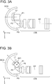
- Fig. 3A and Fig. 3B are diagrams illustrating an axis of rotation when the first prism P1 is made to undergo rotational movement with respect to the second prism P2.
- the first prism P1 undergoes rotational movement with respect to the second prism P2, with the axis of rotation AX1 as a center.
- the center of curvature of the image-side surface of the dome-shaped cover glass DCG is positioned on the axis of rotation AX1.
- Fig. 4A, Fig. 4B , Fig. 4C, and Fig. 4D are a cross-sectional view, a side view, a top view, and a perspective view respectively, showing an arrangement of an endoscope objective optical system according to an example 1.
- a prism P1, a prism P2, and a prism P3 are shown to be unfolded. Therefore, prisms are drawn as plane-parallel plates.
- Fig. 4B , Fig. 4C, and Fig. 4D show the first prism P1, the second prism P2, and the third prism P3 in a non-unfolded state.
- the lens group LNS includes in order from the object side, a concavoplane negative lens L1 having a concave surface directed toward the object side, a planoconvex positive lens L2 having a convex surface directed toward an image side, a biconvex positive lens L3, a biconvex positive lens L4, a biconcave negative lens L5, a plane-parallel plate F, and a plane-parallel plate CG.
- the concavoplane negative lens L1 and the planoconvex positive lens L2 are cemented.
- the biconvex positive lens L4 and the biconcave negative lens L5 are cemented.
- the lens group LNS includes in order from the object side, a positive meniscus lens L2 having a convex surface directed toward an image side, a biconvex positive lens L3, a negative meniscus lens L4 having a convex surface directed toward the object side, a convexoplane positive lens L5 having a convex surface directed toward the object side, a plane-parallel plate F, and a plane-parallel plate CG.
- the negative meniscus lens L4 and the convexoplane positive lens L5 are cemented.
- the plane-parallel plate F is an infrared absorbing filter with a YAG laser cut coating applied to an object side thereof and an LD laser cut coating applied to an image side thereof.
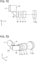
- Fig. 7A, Fig. 7B , Fig. 7C, and Fig. 7D are a cross-sectional view, a side view, a top view, a perspective view respectively, of an endoscope objective optical system according to an example 4.
- a first prism P1, a second prism P2, and a third prism P3 are shown to be unfolded. Therefore, the prisms are drawn as plane-parallel plates.
- Fig. 7B , Fig. 7C, and Fig. 7D show the first prism P1, the second prism P2, and the third prism P3 in a non-unfolded state.
- the endoscope objective optical system according to the example 4 includes in order from an object side, an optical-path deflecting prism group PG and a lens group LNS.
- the optical-path deflecting prism group PG includes a negative meniscus lens L1 having a convex surface directed toward the object side, the first prism P1, the second prism P2, an aperture stop S, and the third prism P3.
- Fig. 8A and Fig. 8B are a side view and a top view respectively, of an endoscope objective optical system according to an example 5.
- a first prism P1, a second prism P2, and a third prism P3 are shown to be in a non-unfolded state.
- Fig. 9A and Fig. 9B are a side view and a top view respectively, of an endoscope objective optical system according to an example 6.
- a first prism P1, a second prism P2, and a third prism P3 are shown to be in a non-unfolded state.
- the plane-parallel plate F is an infrared absorbing filter with a YAG laser cut coating applied to an object side thereof and an LD laser cut coating applied to an image side thereof.
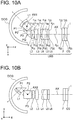
- Fig. 10A and Fig. 10B are a top view and a side view respectively, of an endoscope objective optical system according to an example 7.
- a first prism P1, a second prism P2, and a third prism P3 are shown to be in a non-unfolded state.
- the lens group LNS includes in order from the object side, a positive meniscus lens L2 having a convex surface directed toward an image side, a biconvex positive lens L3, a negative meniscus lens L4 having a convex surface directed toward the object side, a convexoplane positive lens L5 having a convex surface directed toward the object side, a plane-parallel plate L6, a plane-parallel plate F, and a plane-parallel plate CG.
- the negative meniscus lens L4 and the convexoplane positive lens L5 are cemented.
- r denotes a radius of curvature of each lens surface
- d denotes a distance between two lens surfaces
- nd denotes a refractive index of each lens for a d-line
- vd denotes Abbe's number for each lens.
- FL denotes a focal length of the overall system
- Fno denotes an F-value
- ⁇ denotes a half angle of view
- L denotes a total air conversion length (unit mm) of the first prism, the second prism, and the third prism in the optical-path deflecting prism group.
Landscapes
- Physics & Mathematics (AREA)
- Health & Medical Sciences (AREA)
- Life Sciences & Earth Sciences (AREA)
- Optics & Photonics (AREA)
- Surgery (AREA)
- General Physics & Mathematics (AREA)
- Engineering & Computer Science (AREA)
- Animal Behavior & Ethology (AREA)
- Radiology & Medical Imaging (AREA)
- Nuclear Medicine, Radiotherapy & Molecular Imaging (AREA)
- Biophysics (AREA)
- Biomedical Technology (AREA)
- Heart & Thoracic Surgery (AREA)
- Medical Informatics (AREA)
- Molecular Biology (AREA)
- Pathology (AREA)
- General Health & Medical Sciences (AREA)
- Public Health (AREA)
- Veterinary Medicine (AREA)
- Astronomy & Astrophysics (AREA)
- Lenses (AREA)
- Endoscopes (AREA)
- Instruments For Viewing The Inside Of Hollow Bodies (AREA)
Abstract
Description
- The present invention relates to an endoscope objective optical system.
- An endoscope is an apparatus that has been used widely in a medical field and an industrial field. Particularly, in the medical field, images of various sites inside a body cavity are achieved by an endoscope inserted into the body cavity. Diagnosis of a site observed is carried out by using these images . In such manner, endoscopes have been used for observation and diagnosis of various sites inside the body cavity.
- In a case of changing a direction of observation while carrying out observation of inside of body cavity by an endoscope, a front-end side of an inserting portion of the endoscope is to be bent. Accordingly, it is possible to change an observation field of view vertically or in a leftward-rightward direction (refer to Patent Literatures 1, 2, and 3 for example).
-
- Patent Literature 1: International Unexamined Patent Application Publication No.
2012/081349 - Patent Literature 2: Japanese Patent Application Laid-open Publication No.
2006-201796 - Patent Literature 3:
US Unexamined Patent Application Publication No. 2013:0085338 - Here, at the time of observing inside of a body cavity, a space inside the body cavity is narrow in many cases. Consequently, when an endoscope is bent inside the body cavity, a front-end portion interferes with a portion to be observed (a diseased part) which is an object. For this reason, in an arrangement of a conventional technology, sometimes it becomes difficult to change a field of view freely inside the body cavity.
- Moreover, as the front-end portion of the endoscope is bent, even when the front-end portion of the endoscope does not interfere with the portion observed, sometimes the front-end portion is excessively close to the portion to be observed. In this case, there is not enough space for treating the diseased part by a treatment tool.
- The present invention has been made in view of the abovementioned circumstances, and an object of the present invention is to provide an endoscope objective optical system which enables to change a field of view in an arbitrary direction without bending an endoscope, even in a narrow space. Solution to Problem
- To solve the abovementioned issues and to achieve the object, an endoscope objective optical system according to the present invention includes an optical-path deflecting prism group and a lens group, wherein a visual-field direction of the endoscope objective optical system is let to be variable by moving a prism in the optical-path deflecting prism group, and the optical-path deflecting prism group includes in order from an object side, three prisms namely, a first prism, a second prism, and a third prism, and the first prism, the second prism, and the third prism are disposed to be in mutual proximity, and the visual-field direction is let to be variable to a first direction by the first prism undergoing a rotation movement with respect to the second prism, and the visual-field direction is let to be variable to a second direction which differs from the first direction, by the first prism and the second prism undergoing rotation movement integrally with respect to the third prism.
- The present invention shows an effect that it is possible to provide an endoscope objective optical system which enables to change a field of view to an arbitrary direction without bending an endoscope, even in a narrow space.
-
-
Fig. 1A is a perspective view showing an arrangement of an endoscope objective optical system according to a first embodiment; -
Fig. 1B is another perspective view showing an arrangement of the endoscope objective optical system according to the first embodiment; -
Fig. 1C is still another perspective view showing an arrangement of the endoscope objective optical system according to the first embodiment; -
Fig. 1D is still another perspective view showing an arrangement of the endoscope objective optical system according to the first embodiment; -
Fig. 1E is still another perspective view showing an arrangement of the endoscope objective optical system according to the first embodiment; -
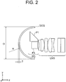
Fig. 2 is a cross-sectional view showing an arrangement of an endoscope objective optical system according to a second embodiment; -
Fig. 3A is a cross-sectional view showing an arrangement of an endoscope objective optical system according to a third embodiment; -
Fig. 3B is another cross-sectional view showing an arrangement of the endoscope objective optical system according to the third embodiment; -
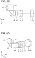
Fig. 3C is still another cross-sectional view showing an arrangement of the endoscope objective optical system according to the third embodiment; -
Fig. 3D is still another cross-sectional view showing an arrangement of the endoscope objective optical system according to the third embodiment; -
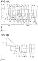
Fig. 4A is a cross-sectional view showing an arrangement of an endoscope objective optical system according to an example 1; -
Fig. 4B is a side view of the endoscope objective optical system according to the example 1; -
Fig. 4C is a top view of the endoscope objective optical system according to the example 1; -
Fig. 4D is a perspective view of the endoscope objective optical system according to the example 1; -
Fig. 5A is a cross-sectional view showing an arrangement of an endoscope objective optical system according to an example 2; -
Fig. 5B is a side view of the endoscope objective optical system according to the example 2; -
Fig. 5C is a top view of the endoscope objective optical system according to the example 2; -
Fig. 5D is a perspective view of the endoscope objective optical system according to the example 2; -
Fig. 6A is a cross-sectional view showing an arrangement of an endoscope objective optical system according to an example 3; -
Fig. 6B is a side view of the endoscope objective optical system according to the example 3; -
Fig. 6C is a top view of the endoscope objective optical system according to the example 3; -
Fig. 6D is a perspective view of the endoscope objective optical system according to the example 3; -
Fig. 7A is a cross-sectional view showing an arrangement of an endoscope objective optical system according to an example 4; -
Fig. 7B is a side view of the endoscope objective optical system according to the example 4; -
Fig. 7C is a top view of the endoscope objective optical system according to the example 4; -
Fig. 7D is a perspective view of the endoscope objective optical system according to the example 4; -
Fig. 8A is a side view of an endoscope objective optical system according to an example 5; -
Fig. 8B is a top view of the endoscope objective optical system according to the example 5; -
Fig. 9A is a side view of an endoscope objective optical system according to an example 6; -
Fig. 9B is a top view of the endoscope objective optical system according to the example 6; -
Fig. 10A is a top view of an endoscope objective optical system according to an example 7; and -
Fig. 10B is a side view of the endoscope objective optical system according to the example 7. - Reasons for and effects of adopting such arrangement for an endoscope objective optical system according to the present embodiment will be described below by using the accompanying diagrams. However, the present invention is not limited to the embodiments described below.
-
Fig. 1A, Fig. 1B, Fig. 1C ,Fig. 1D, and Fig. 1E are diagrams showing a schematic arrangement of an endoscope objective optical system according to a first embodiment. - The endoscope objective optical system includes an optical-path deflecting prism group PG and a lens group LNS. A visual-field direction A is let to be variable by moving a prism in the optical-path deflecting prism group PG.
- The optical-path deflecting prism group PG includes in order from an object side, three prisms namely, a first prism P1, a second prism P2, and a third prism P3. Each of the first prism P1, the second prism P2, and the third prism P3 is a right-angle prism. The first prism P1, the second prism P2, and the third prism P3 are disposed to be in mutual proximity. Moreover, the visual-field direction A is let to be variable to a first direction DP1 by the first prism P1 undergoing a rotational movement with respect to the second prism P2. Furthermore, the visual-field direction A is let to be variable to a second direction DR2 which differs from the first direction DR1, by the first prism P1 and the second prism P2 undergoing rotational movement integrally with respect to the third prism P3.
- Accordingly, it is possible to change the field of view to an arbitrary direction without bending the endoscope, even in a narrow space. Moreover, it is preferable that the first direction DR1 and the second direction DR2 are orthogonal at 90 degrees.
- Moreover, according to a preferable aspect of the present invention, it is preferable to satisfy the following conditional expression (1).

- L denotes a total air conversion length (unit mm) of the first prism, the second prism, and the third prism in the optical-path deflecting prism group, and here
- the total air conversion length is a value obtained by summing up a value obtained by dividing a length of an optical axis passing through the first prism P1 by a refractive index for a d-line nd1 of a glass material of the first prism P1, a value obtained by dividing a length of an optical axis passing through the second prism P2 by a refractive index for the d-line nd2 of a glass material of the second prism P2, and a value obtained by dividing a length of an optical axis passing through the third prism by a refractive index for the d-line nd3 of a glass material of the third prism P3, and
- FL denotes a focal length (unit mm) of the endoscope objective optical system.
- Conditional expression (1) regulates an appropriate size of the optical-path deflecting prism group PG. By satisfying conditional expression (1), it is possible to make small the size of the optical-path deflecting prism group PG. Accordingly, it is possible to built-in the endoscope objective optical system in an inserting portion of an endoscope having a small diameter.
- When a value falls below a lower limit value of conditional expression (1), a size of each of the first prism P1, the second prism P2, and the third prism P3 becomes excessively small with respect to the focal length of the endoscope objective optical system. Consequently, it is not possible to make thick light rays of a light beam having a large diameter pass through the first prism P1, the second prism P2, and the third prism P3. As a result, an F-value of the endoscope objective optical system becomes large, and an image quality is degraded.
- When an upper limit value of conditional expression (1) is exceeded, the size of each of the first prism P1, the second prism P2, and the third prism P3 becomes large in a radial direction of endoscope or in other words, in a direction perpendicular to a longitudinal direction of endoscope. Accordingly, an outer diameter of the optical-path deflecting prism group in the endoscope objective optical system becomes large, and the optical-path deflecting prism group cannot be built-in in the inserting portion of the endoscope.
- Moreover, according to a preferable aspect of the present invention, it is desirable to dispose a dome-shaped cover glass DCG between the endoscope objective optical system and an object as shown in
Fig. 2 , and it is desirable that a thickness t of the dome-shaped cover glass DCG satisfies the following conditional expression (2).
- D denotes an outer diameter (unit mm) of the dome-shaped cover glass DCG,
- t denotes the thickness (unit mm) of the dome-shaped cover glass DCG,
- Fno denotes an F-value of the endoscope objective optical system, and
- R denotes a radius of curvature (unit mm) of an object-side surface of the dome-shaped cover glass, and moreover
- when the outer diameter of the dome-shaped cover glass is not uniform, the largest portion is let to be the outer diameter (D), and
- when the thickness of the dome-shaped cover glass is not uniform, the thickest portion in an effective range is let to be the thickness (t).
- Conditional expression (2) can also be expressed as follows.


- Conditional expression (2) regulates an appropriate thickness t of the dome-shaped cover glass DCG. Here, since the visual-field direction is let to be variable by moving the first prism P1, the second prism P2, and the third prism P3, it is difficult to make a spherical center (center of curvature) of a dome of the hemispherical dome-shaped cover glass DCG and an entrance pupil of the endoscope objective optical system coincide. Therefore, there is a degradation of image quality due to the dome-shaped cover glass DCG. Moreover, the dome-shaped cover glass is required to have a predetermined strength as a cover glass. Therefore, it is desirable that the thickness t satisfies conditional expression (2) form a point of view of reducing degradation of image quality and securing the strength.
- When an upper limit value of conditional expression (2) is exceeded, the thickness t becomes thick and the image quality is degraded. When a value falls below a lower limit value of conditional expression (2), the strength necessary as a cover glass cannot be achieved.
- Moreover, according to a preferable aspect of the present invention, it is desirable to dispose a dome-shaped cover glass DCG between the endoscope objective optical system and an object as shown in
Fig. 3A, Fig. 3B , andFig. 3C , and it is desirable that a center of curvature of an image-side surface of the dome-shaped cover glass DCG is positioned on an axis of rotation AX1 when the first prism P1 is made to undergo rotational movement with respect to the second prism P2, and is positioned on an axis of rotation AX2 when the first prism P1 and the second prism P2 are made to undergo rotational movement integrally with respect to the third prism P3. -
Fig. 3A and Fig. 3B are diagrams illustrating an axis of rotation when the first prism P1 is made to undergo rotational movement with respect to the second prism P2. The first prism P1 undergoes rotational movement with respect to the second prism P2, with the axis of rotation AX1 as a center. The center of curvature of the image-side surface of the dome-shaped cover glass DCG is positioned on the axis of rotation AX1. - Accordingly, when a lens L1 and the first prism P1 are rotated with the axis of rotation AX1 as the center of rotation, in any of the rotating states, the lens L1 and the first prism P1 are capable of maintaining a distance from the image-side surface of the dome-shaped cover glass DCG to be constant. As a result, it is possible to prevent interference, or in other words, a contact with the dome-shaped cover glass DCG due to the rotational movement of the first prism P1. Consequently, it is possible to secure a visual-field variation range to be even wider.
- Next,
Fig. 3C and Fig. 3D are diagrams illustrating an axis of rotation when the first prism P1 and the second prism P2 are made to undergo rotational movement integrally with respect to the third prism P3. The first prism P1 and the second prism P2 undergo rotational movement integrally with the axis of rotation AX2 as a center, with respect to the third prism P3. The center of curvature of the image-side surface of the dome-shaped cover glass DCG is positioned on the axis of rotation AX2. - Accordingly, in any of the rotating states in which the lens L1 and the first prism P1, and the second prism P2 are rotated with the axis of rotation AX2 as the center of rotation, the lens L1 and the first prism P1, and the second prism P2 are capable of maintaining a constant distance from the image-side surface of the dome-shaped cover glass DCG. As a result, it is possible to prevent interference, or in other words, a contact, with the dome-shaped cover glass DCG due to the rotational movement of the lens L1 and the first prism P1, and the second prism P2. Consequently, it is possible to secure a visual-field variation range to be even wider.
- Examples will be described below.
-
Fig. 4A, Fig. 4B ,Fig. 4C, and Fig. 4D are a cross-sectional view, a side view, a top view, and a perspective view respectively, showing an arrangement of an endoscope objective optical system according to an example 1. InFig. 4A , a prism P1, a prism P2, and a prism P3 are shown to be unfolded. Therefore, prisms are drawn as plane-parallel plates.Fig. 4B ,Fig. 4C, and Fig. 4D show the first prism P1, the second prism P2, and the third prism P3 in a non-unfolded state. - The endoscope objective optical system according to the example 1 includes in order from an object side, an optical-path deflecting prism group PG and a lens group LNS. The optical-path deflecting prism group PG includes a first prism P1, a second prism P2, an aperture stop S, and a third prism P3.
- The lens group LNS includes in order from the object side, a concavoplane negative lens L1 having a concave surface directed toward the object side, a planoconvex positive lens L2 having a convex surface directed toward an image side, a biconvex positive lens L3, a biconvex positive lens L4, a biconcave negative lens L5, a plane-parallel plate F, and a plane-parallel plate CG. Here, the concavoplane negative lens L1 and the planoconvex positive lens L2 are cemented. Moreover, the biconvex positive lens L4 and the biconcave negative lens L5 are cemented.
- The plane-parallel plate F is an infrared absorbing filter with a YAG (Yttrium Aluminum Garnet) laser cut coating applied to an object side thereof and an LD laser cut coating applied to an image side thereof.
-
Fig. 5A, Fig. 5B ,Fig. 5C, and Fig. 5D are a cross-sectional view, a side view, a top view, and a perspective view respectively, showing an arrangement of an endoscope objective optical system according to an example 2. InFig. 5A , a first prism P1, a second prism P2, and a third prism P3 are shown to be unfolded. Therefore, the prisms are drawn as plane-parallel plates.Fig. 5B ,Fig. 5C, and Fig. 5D show the first prism P1, the second prism P2, and the third prism P3 in a non-unfolded state. - The endoscope objective optical system according to the example 2 includes in order from an object side, an optical-path deflecting prism group PG and a lens group LNS. The optical-path deflecting prism group PG includes a negative meniscus lens L1 having a convex surface directed toward the object side, the first prism P1, the second prism P2, an aperture stop S, and the third prism P3.
- The lens group LNS includes in order from the object side, a positive meniscus lens L2 having a convex surface directed toward an image side, a biconvex positive lens L3, a negative meniscus lens L4 having a convex surface directed toward the object side, a convexoplane positive lens L5 having a convex surface directed toward the object side, a plane-parallel plate F, and a plane-parallel plate CG. Here, the negative meniscus lens L4 and the convexoplane positive lens L5 are cemented.
- The plane-parallel plate F is an infrared absorbing filter with a YAG laser cut coating applied to an object side thereof and an LD laser cut coating applied to an image side thereof.
-
Fig. 6A, Fig. 6B ,Fig. 6C, and Fig. 6D are a cross-sectional view, a side view, a top view, and a perspective view respectively, of an endoscope objective optical system according to an example 3. InFig. 6A , a first prism P1, a second prism P2, and a third prism P3 are shown to be unfolded. Therefore, the prisms are drawn as plane-parallel plates.Fig. 6B ,Fig. 6C, and Fig. 6D show the first prism P1, the second prism P2, and the third prism P3 in a non-unfolded state. - The endoscope objective optical system according to the example 3 includes in order from an object side, an optical-path deflecting prism group PG and a lens group LNS. The optical-path deflecting prism group PG includes the first prism P1, the second prism P2, an aperture stop S, and the third prism P3.
- The lens group LNS includes in order from the object side, a concavoplane negative lens L1 having a concave surface directed toward the object side, a planoconvex positive lens L2 having a convex surface directed toward an image side, a biconvex positive lens L3, a biconvex positive lens L4, a biconcave negative lens L5, a plane-parallel plate F, and a plane-parallel plate CG. Here, the concavoplane negative lens L1 and the planoconvex positive lens L2 are cemented. Moreover, the biconvex positive lens L4 and the biconcave negative lens L5 are cemented.
- The plane-parallel plate F is an infrared absorbing filter with a YAG laser cut coating applied to an object side thereof and an LD laser cut coating applied to an image side thereof.
-
Fig. 7A, Fig. 7B ,Fig. 7C, and Fig. 7D are a cross-sectional view, a side view, a top view, a perspective view respectively, of an endoscope objective optical system according to an example 4. InFig. 7A , a first prism P1, a second prism P2, and a third prism P3 are shown to be unfolded. Therefore, the prisms are drawn as plane-parallel plates.Fig. 7B ,Fig. 7C, and Fig. 7D show the first prism P1, the second prism P2, and the third prism P3 in a non-unfolded state. - The endoscope objective optical system according to the example 4 includes in order from an object side, an optical-path deflecting prism group PG and a lens group LNS. The optical-path deflecting prism group PG includes a negative meniscus lens L1 having a convex surface directed toward the object side, the first prism P1, the second prism P2, an aperture stop S, and the third prism P3.
- The lens group LNS includes in order from the object side, a positive meniscus lens L2 having a convex surface directed toward an image side, a positive meniscus lens L3 having a convex surface directed toward the object side, a negative meniscus lens L4 having a convex surface directed toward the object side, a biconvex positive lens L5, a plane-parallel plate F, and a plane-parallel plate CG. Here, the negative meniscus lens L4 and the biconvex positive lens L5 are cemented.
- The plane-parallel plate F is an infrared absorbing filter with a YAG laser cut coating applied to an object side thereof and an LD laser cut coating applied to an image side thereof.
-
Fig. 8A and Fig. 8B are a side view and a top view respectively, of an endoscope objective optical system according to an example 5. InFig. 8A and Fig. 8B , a first prism P1, a second prism P2, and a third prism P3 are shown to be in a non-unfolded state. - The endoscope objective optical system according to the example 5 includes in order from an object side, a dome-shaped cover glass DCG, an optical-path deflecting prism group PG, and a lens group LNS. The optical-path deflecting prism group PG includes the first prism P1, the second prism P2, an aperture stop S, and the third prism P3.
- The lens group LNS includes in order from the object side, a concavoplane negative lens L1 having a concave surface directed toward the object side, a planoconvex positive lens L2 having a convex surface directed toward an image side, a biconvex positive lens L3, a biconvex positive lens L4, a biconcave negative lens L5, a plane-parallel plate F, and a plane-parallel plate CG. Here, the concavoplane negative lens L1 and the planoconvex positive lens L2 are cemented. Moreover, the biconvex positive lens L4 and the biconcave negative lens L5 are cemented.
- The plane-parallel plate F is an infrared absorbing filter with a YAG laser cut coating applied to an object side thereof and an LD laser cut coating applied to an image side thereof.
-
Fig. 9A and Fig. 9B are a side view and a top view respectively, of an endoscope objective optical system according to an example 6. InFig. 9A and Fig. 9B , a first prism P1, a second prism P2, and a third prism P3 are shown to be in a non-unfolded state. - The endoscope objective optical system according to the example 6 includes in order from an object side, a dome-shaped cover glass DCG, an optical-path deflecting prism group PG, and a lens group LNS. The optical-path deflecting prism group PG includes the first prism P1, the second prism P2, an aperture stop S, and the third prism P3.
- The lens group LNS includes in order from the object side, a concavoplane negative lens L1 having a concave surface directed toward the object side, a planoconvex positive lens L2 having a convex surface directed toward an image side, a biconvex positive lens L3, a biconvex positive lens L4, a biconcave negative lens L5, a plane-parallel plate F, and a plane-parallel plate CG. Here, the concavoplane negative lens L1 and the planoconvex positive lens L2 are cemented. Moreover, the biconvex positive lens L4 and the biconcave negative lens L5 are cemented.
- The plane-parallel plate F is an infrared absorbing filter with a YAG laser cut coating applied to an object side thereof and an LD laser cut coating applied to an image side thereof.
-
Fig. 10A and Fig. 10B are a top view and a side view respectively, of an endoscope objective optical system according to an example 7. InFig. 10A and Fig. 10B , a first prism P1, a second prism P2, and a third prism P3 are shown to be in a non-unfolded state. - The endoscope objective optical system according to the example 7 includes in order from an object side, a dome-shaped cover glass DCG, an optical-path deflecting prism group PG, and a lens group LNS. The optical-path deflecting prism group PG includes a negative meniscus lens L1 having a convex surface directed toward the object side, the first prism P1, the second prism P2, an aperture stop S, and the third prism P3.
- The lens group LNS includes in order from the object side, a positive meniscus lens L2 having a convex surface directed toward an image side, a biconvex positive lens L3, a negative meniscus lens L4 having a convex surface directed toward the object side, a convexoplane positive lens L5 having a convex surface directed toward the object side, a plane-parallel plate L6, a plane-parallel plate F, and a plane-parallel plate CG. Here, the negative meniscus lens L4 and the convexoplane positive lens L5 are cemented.
- The plane-parallel plate F is an infrared absorbing filter with a YAG laser cut coating applied to an object side thereof and an LD laser cut coating applied to an image side thereof.
- Numerical data for each example is shown below. Regarding symbols, apart from the symbols mentioned above, r denotes a radius of curvature of each lens surface, d denotes a distance between two lens surfaces, nd denotes a refractive index of each lens for a d-line, and vd denotes Abbe's number for each lens. Moreover, FL denotes a focal length of the overall system, Fno denotes an F-value, ω denotes a half angle of view, and L denotes a total air conversion length (unit mm) of the first prism, the second prism, and the third prism in the optical-path deflecting prism group. Here, the total air conversion length is a value obtained by summing up a value obtained by dividing a length of an optical axis passing through the first prism by a refractive index for the d-line nd1 of a glass material of the first prism, a value obtained by dividing a length of an optical axis passing through the second prism by a refractive index for the d-line nd2 of a glass material of the second prism, and a value obtained by dividing a length of an optical axis passing through the third prism by a refractive index for the d-line nd3 of a glass material of the third prism. Moreover, a reflecting surface is marked with '*'.
- Unit mm
Surface dataSurface no. r d nd νd Object plane ∞ 35.230 1 ∞ 0.415 1.883 40.765 2* ∞ 0.415 1.883 40.765 3 ∞ 0.050 4 ∞ 0.277 1.883 40.765 5* ∞ 0.277 1.883 40.765 6 ∞ 0.025 7(Stop) ∞ 0.025 8 ∞ 0.277 1.883 40.765 9* ∞ 0.277 1.883 40.765 10 ∞ 0.116 11 -0.652 0.126 1.518 58.902 12 ∞ 0.277 1.883 40.765 13 -0.983 0.015 14 3.984 0.252 1.883 40.765 15 -3.162 0.015 16 1.166 0.352 1.693 50.811 17 -2.585 0.126 1.959 17.471 18 1.622 0.338 19 ∞ 0.252 1.516 64.142 20 ∞ 0.352 1.614 50.200 Image pickup surface ∞ FL 1 L 1.029 Fno 4.55 ω 60° - Unit mm
Surface dataSurface no. r d nd νd Object plane ∞ 25.253 1 1.852 0.126 1.806098 40.926 2 0.616 0.149 3 ∞ 0.316 2.003300 28.273 4* ∞ 0.316 2.003300 28.273 5 ∞ 0.063 6 ∞ 0.410 2.003300 28.273 7* ∞ 0.316 2.003300 28.273 8 ∞ 0.076 9(Stop) ∞ 0.019 10 ∞ 0.379 2.003300 28.273 11* ∞ 0.379 2.003300 28.273 12 ∞ 0.082 13 -2.751 0.253 1.806098 40.882 14 -1.547 0.019 15 2.321 0.316 1.882997 40.765 16 -5.742 0.237 17 2.179 0.158 1.846660 23.778 18 0.804 0.442 1.496999 81.546 19 ∞ 1.313 20 ∞ 0.253 1.516330 64.142 21 ∞ 0.221 1.613500 50.200 Image pickup surface ∞ FL 1 L 1.056 Fno 4.48 ω 60° - Unit mm
Surface dataSurface no. r d nd νd Object plane ∞ 30.822 1 ∞ 0.363 1.883 40.765 2* ∞ 0.363 1.883 40.765 3 ∞ 0.044 4 ∞ 0.242 1.883 40.765 5* ∞ 0.242 1.883 40.765 6 ∞ 0.022 7(Stop) ∞ 0.022 8 ∞ 0.242 1.883 40.765 9* ∞ 0.242 1.883 40.765 10 ∞ 0.101 11 -0.652 0.126 1.518 58.90 12 ∞ 0.277 1.883 40.765 13 -0.983 0.015 14 3.984 0.252 1.883 40.765 15 -3.162 0.015 16 1.166 0.352 1.693 50.811 17 -2.585 0.126 1.959 17.471 18 1.622 0.390 19 ∞ 0.220 1.516 64.142 20 ∞ 0.308 1.614 50.200 Image pickup surface ∞ FL 1 L 0.9 Fno 5.2 ω 50° - Unit mm
Surface dataSurface no. r d nd νd Object plane ∞ 35.852 1 5.617835 0.1791428 1.806098 40.925996 2 0.819238 0.2025591 3 ∞ 0.4477511 2.003300 28.27328 4* ∞ 0.4477511 2.003300 28.27328 5 ∞ 0.08955022 6 ∞ 0.5820765 2.003300 28.27328 7* ∞ 0.4477511 2.003300 28.27328 8 ∞ 0.1074603 9(Stop) ∞ 0.02686507 10 ∞ 0.5373013 2.003300 28.27328 11* ∞ 0.5373013 2.003300 28.27328 12 ∞ 0.1164153 13 -13.4875 0.3582857 1.806098 40.881692 14 -2.391508 0.02686507 15 2.447604 0.4477511 1.882997 40.765107 16 18.23645 0.2325315 17 2.986169 0.2238756 1.846660 23.77794 18 1.052876 0.6268516 1.496999 81.545888 19 -5.667179 1.478543 20 ∞ 0.3582857 1.516330 64.142022 21 ∞ 0.3134258 1.613500 50.2 Image pickup surface ∞ FL 1 L 1.498 Fno 3.73 ω 88.6° - Unit mm
Surface dataSurface no. r d nd νd Object plane ∞ 70 1 ∞ 0.825 1.882997 40.765 2* ∞ 0.825 1.882997 40.765 3 ∞ 0.1 4 ∞ 0.55 1.882997 40.76 5* ∞ 0.55 1.882997 40.765 6 ∞ 0.1 7 (Stop) ∞ 0 8 ∞ 0.55 1.882997 40.765 9* ∞ 0.55 1.882997 40.765 10 ∞ 0.23 11 -1.295 0.25 1.518229 58.902 12 ∞ 0.55 1.882997 40.765 13 -1.953 0.03 14 7.916 0.5 1.882997 40.765 15 -6.283 0.03 16 2.316 0.7 1.693495 50.811 17 -5.137 0.25 1.959060 17.471 18 3.222 0.658 19 ∞ 0.5 1.516330 64.142 20 ∞ 0.7 1.617722 49.832 Image pickup surface ∞ -
FL 1.99 L 2.045 Fno 4.55 ω 60° - dome-shaped cover glass
- glass material sapphire
- outer diameter D 5.4
- radius of curvature of an object-side surface R 2.7
- thickness t 0.17
-
FL 1.99 L 2.045 Fno 4.55 ω 60° - dome-shaped cover glass
- glass material sapphire
- outer diameter D 5.4
- radius of curvature of an object-side surface R 2.7
- thickness t 0.6
- Unit mm
Surface dataSurface no. r d nd νd Object plane ∞ 40.00947 1 2.932838 0.2000473 1.806098 40.925996 2 0.9752386 0.2364146 3 ∞ 0.5 2.003300 28.273280 4* ∞ 0.5 2.003300 28.273280 5 ∞ 0.1 6 ∞ 0.65 2.003300 28.273280 7* ∞ 0.5 2.003300 28.273280 8 ∞ 0.12 9(Stop) ∞ 0.03 10 ∞ 0.600142 2.003300 28.273280 11* ∞ 0.600142 2.003300 28.273280 12 ∞ 0.13 13 -4.357899 0.4000947 1.806098 40.881692 14 -2.450486 0.03 15 3.676665 0.5 1.882997 40.765107 16 -9.095195 0.3749307 17 3.451026 0.25 1.846660 23.777940 18 1.273489 0.7 1.496999 81.545888 19 ∞ 0.03 20 ∞ 0.3 1.516330 64.142022 21 ∞ 1.840969 22 ∞ 0.4000947 1.516330 64.142022 23 ∞ 0.35 1.613500 50.200000 Image pickupsurface ∞ FL 1.584 L 1.672 Fno 4.479 ω 60° - dome-shaped cover glass
- glass material sapphire
- outer diameter D 5.4
- radius of curvature of an object-side surface R 2.7
- thickness t 0.3
- Numerical values of the conditional expressions of each of examples are shown below.
Conditional expression Example1 Example2 Example3 (1) L/FL 1.029 1.056 0.9 Conditional expression Example4 Example5.6 Example7 (1) L/FL 1.4987 1.0276 1.0556 Conditional expression Example5 Example6 Example7 (2a) t/D 0.0315 0.1111 0.0556 (2b) t/(Fno×R) 0.0138 0.0488 0.0248 - As described above, according to the present invention it is possible to provide an endoscope objective optical system which enables to change a field of view to an arbitrary direction without bending an endoscope, even in a narrow space.
- Various embodiments of the present invention have been described above. However, the present invention is not limited to these embodiments, and an embodiment in which the arrangements of these embodiments are combined appropriately without departing from the scope of the invention also fall under the category of the present invention.
- As described above, the present invention is useful for an endoscope objective optical system to be used in a narrow space, and particularly is suitable for an endoscope objective optical system in which a field of view is let to be variable to an arbitrary direction.
-
- PG optical-path deflecting prism group
- LNS lens group
- P1 first prism
- P2 second prism
- P3 third prism
- AX1 axis of rotation
- AX2 axis of rotation
- DCG dome-shaped cover glass
- L1, L2, L3, L4, L5 lens
- S aperture stop
Claims (4)
- An endoscope objective optical system, comprising:an optical-path deflecting prism group; anda lens group, whereina visual-field direction of the endoscope objective optical system is let to be variable by moving a prism in the optical-path deflecting prism group, andthe optical-path deflecting prism group includes in order from an object side, three prisms namely, a first prism, a second prism, and a third prism, and the first prism, the second prism, and the third prism are disposed to be in mutual proximity, and the visual-field direction is let to be variable to a first direction by the first prism undergoing a rotational movement with respect to the second prism, and furthermore, the visual-field direction is let to be variable to a second direction which differs from the first direction, by the first prism and the second prism undergoing rotational movement integrally with respect to the third prism.
- The endoscope objective optical system according to claim 1, wherein the endoscope objective optical system satisfies the following conditional expression (1)
 L denotes a total air conversion length (unit mm) of the first prism, the second prism, and the third prism in the optical-path deflecting prism group, and herethe total air conversion length is a value obtained by summing up a value obtained by dividing a length of an optical axis passing through the first prism by a refractive index for a d-line nd1 of a glass material of the first prism, a value obtained by dividing a length of an optical axis passing through the second prism by a refractive index for the d-line nd2 of a glass material of the second prism, and a value obtained by dividing a length of an optical axis passing through the third prism by a refractive index for the d-line nd3 of a glass material of the third prism, andFL denotes a focal length (unit mm) of the endoscope objective optical system.
 - The endoscope objective optical system according to one of claims 1 and 2, wherein
a dome-shaped cover glass is disposed between the endoscope objective optical system and an object, and
a thickness t of the dome-shaped cover glass satisfies the following conditional expression (2) D denotes an outer diameter (unit mm) of the dome-shaped cover glass,t denotes the thickness (unit mm) of the dome-shaped cover glass,Fno denotes an F-value of the endoscope objective optical system, andR denotes a radius of curvature (unit mm) of an object-side surface of the dome-shaped cover glass, and moreoverwhen the outer diameter of the dome-shaped cover glass is not uniform, the largest portion is let to be the outer diameter (D), andwhen the thickness of the dome-shaped cover glass is not uniform, the thickest portion in an effective range is let to be the thickness (t).
 - The endoscope objective optical system according to one of claims 1 to 3, wherein
a dome-shaped cover glass is disposed between the endoscope objective optical system and an object, and
a center of curvature of an image-side surface of the dome-shaped cover glass is positioned on an axis of rotation when the first prism is made to undergo rotational movement with respect to the second prism, and is positioned on an axis of rotation when the first prism and the second prism are made to undergo rotational movement integrally with respect to the third prism.
Applications Claiming Priority (2)
| Application Number | Priority Date | Filing Date | Title |
|---|---|---|---|
| JP2015079789 | 2015-04-09 | ||
| PCT/JP2016/061368 WO2016163447A1 (en) | 2015-04-09 | 2016-04-07 | Endoscope objective optical system |
Publications (1)
| Publication Number | Publication Date |
|---|---|
| EP3282299A1 true EP3282299A1 (en) | 2018-02-14 |
Family
ID=57073123
Family Applications (1)
| Application Number | Title | Priority Date | Filing Date |
|---|---|---|---|
| EP16776613.8A Withdrawn EP3282299A1 (en) | 2015-04-09 | 2016-04-07 | Endoscope objective optical system |
Country Status (5)
| Country | Link |
|---|---|
| US (1) | US10054783B2 (en) |
| EP (1) | EP3282299A1 (en) |
| JP (1) | JP6043041B1 (en) |
| CN (1) | CN107003502B (en) |
| WO (1) | WO2016163447A1 (en) |
Families Citing this family (9)
| Publication number | Priority date | Publication date | Assignee | Title |
|---|---|---|---|---|
| CN107250875B (en) * | 2015-10-01 | 2019-08-20 | 奥林巴斯株式会社 | Endoscope optical system unit |
| DE102017113274A1 (en) * | 2017-06-16 | 2018-12-20 | avateramedical GmBH | Camera lens for an endoscope and endoscope |
| JPWO2019049997A1 (en) * | 2017-09-10 | 2020-10-15 | カイロス株式会社 | Endoscope system |
| US11032481B2 (en) * | 2018-07-06 | 2021-06-08 | Medos International Sarl | Camera scope electronic variable prism |
| US10429150B1 (en) * | 2019-02-04 | 2019-10-01 | Kruger Optical, Inc. | Compact optical sight |
| CN110368596B (en) * | 2019-07-24 | 2020-12-08 | 郑州大学第一附属医院 | Rheumatology and Immunology Infrared Therapy Device |
| JP6840216B2 (en) * | 2019-12-13 | 2021-03-10 | 株式会社タムロン | Optical system and imaging device |
| CN112790721B (en) * | 2021-01-29 | 2023-07-18 | 之江实验室 | A miniature endoscopic microscope objective lens group and probe for high-resolution lateral imaging |
| CN116203776B (en) * | 2023-05-05 | 2023-09-12 | 荣耀终端有限公司 | Prism assembly, zoom lens, camera module and terminal equipment |
Family Cites Families (15)
| Publication number | Priority date | Publication date | Assignee | Title |
|---|---|---|---|---|
| JPS4953847A (en) * | 1972-09-25 | 1974-05-25 | ||
| DE2347914C3 (en) | 1972-09-25 | 1979-01-11 | Olympus Optical Co., Ltd., Tokio | Endoscope with image transmission fiber optics and a first and rotatable second reflective element |
| GB1494082A (en) * | 1974-02-20 | 1977-12-07 | Secr Social Service Brit | Viewing devices |
| JPS63262613A (en) * | 1987-04-20 | 1988-10-28 | Olympus Optical Co Ltd | Stereoscopic vision endoscope device |
| US5643176A (en) * | 1995-02-01 | 1997-07-01 | Power Analytics Corporation | Endoscopic instrument with variable viewing angle |
| JPH0961722A (en) * | 1995-08-23 | 1997-03-07 | Nikon Corp | Variable tilt lens barrel device |
| US6638216B1 (en) * | 2000-08-30 | 2003-10-28 | Durell & Gitelis, Inc. | Variable view arthroscope |
| JP2006201796A (en) | 2005-01-21 | 2006-08-03 | Karl Storz Development Corp | Variable directivity of viewing apparatus equipped with image sensor at tip |
| US9182577B2 (en) | 2005-01-21 | 2015-11-10 | Karl Storz Imaging, Inc. | Variable direction of view instrument with distal image sensor |
| US7221522B2 (en) | 2005-01-28 | 2007-05-22 | Karl Storz Development Corp. | Optical system for variable direction of view instrument |
| US20100030031A1 (en) * | 2008-07-30 | 2010-02-04 | Acclarent, Inc. | Swing prism endoscope |
| EP2474851B1 (en) | 2009-09-01 | 2016-12-14 | Olympus Corporation | Objective optical system |
| WO2012081349A1 (en) * | 2010-12-15 | 2012-06-21 | オリンパスメディカルシステムズ株式会社 | Endoscope optical system |
| EP2574268B1 (en) | 2011-09-30 | 2017-07-12 | Karl Storz GmbH & Co. KG | Endoscope with adjustable view angle |
| US9345393B2 (en) * | 2012-03-13 | 2016-05-24 | Panasonic Intellectual Property Management Co., Ltd. | Endoscope camera |
-
2016
- 2016-04-07 EP EP16776613.8A patent/EP3282299A1/en not_active Withdrawn
- 2016-04-07 CN CN201680003971.9A patent/CN107003502B/en active Active
- 2016-04-07 JP JP2016556044A patent/JP6043041B1/en active Active
- 2016-04-07 WO PCT/JP2016/061368 patent/WO2016163447A1/en not_active Ceased
-
2017
- 2017-08-01 US US15/666,532 patent/US10054783B2/en active Active
Also Published As
| Publication number | Publication date |
|---|---|
| US10054783B2 (en) | 2018-08-21 |
| CN107003502A (en) | 2017-08-01 |
| WO2016163447A1 (en) | 2016-10-13 |
| JPWO2016163447A1 (en) | 2017-04-27 |
| CN107003502B (en) | 2019-07-30 |
| JP6043041B1 (en) | 2016-12-14 |
| US20170329124A1 (en) | 2017-11-16 |
Similar Documents
| Publication | Publication Date | Title |
|---|---|---|
| EP3282299A1 (en) | Endoscope objective optical system | |
| CN105892037B (en) | Objective lens for endoscope and endoscope | |
| US8098441B2 (en) | Objective lens for endoscopes | |
| US8947785B2 (en) | Endoscope objective lens and endoscope | |
| EP2960701A1 (en) | Endoscope objective optical system, and imaging device | |
| EP3214475A1 (en) | Objective optical system for endoscope | |
| EP1980889A1 (en) | Endoscope objective lens and endoscope | |
| EP3037859A1 (en) | Enlarging endoscope optical system | |
| EP2980624A1 (en) | Optical system for endoscope | |
| US8922916B2 (en) | Endoscope objective lens and endoscope | |
| EP3312652A1 (en) | Endoscope objective optical system | |
| EP2662718B1 (en) | Optical system for endoscope | |
| EP2871508A1 (en) | Objective optical system for endoscope | |
| EP3316016A1 (en) | Optical system of object for endoscope | |
| US8715170B2 (en) | Objective optical system for endoscope | |
| EP3159725A1 (en) | Objective optical system for endoscope | |
| JP2017142295A (en) | Endoscope objective lens and endoscope | |
| CN110251049A (en) | Endoscope lens | |
| EP3382438A1 (en) | Endoscope objective optical system | |
| EP3306388A1 (en) | Imaging unit | |
| EP2618196A1 (en) | Objective optical system for endoscope | |
| CN115210624B (en) | Endoscope objective optical system and endoscope | |
| US9804381B2 (en) | Endoscope objective optical system | |
| US10884223B2 (en) | Objective optical system for endoscope | |
| CN114600026B (en) | Objective optical system and endoscope for endoscope |
Legal Events
| Date | Code | Title | Description |
|---|---|---|---|
| STAA | Information on the status of an ep patent application or granted ep patent |
Free format text: STATUS: THE INTERNATIONAL PUBLICATION HAS BEEN MADE |
|
| PUAI | Public reference made under article 153(3) epc to a published international application that has entered the european phase |
Free format text: ORIGINAL CODE: 0009012 |
|
| STAA | Information on the status of an ep patent application or granted ep patent |
Free format text: STATUS: REQUEST FOR EXAMINATION WAS MADE |
|
| 17P | Request for examination filed |
Effective date: 20171024 |
|
| AK | Designated contracting states |
Kind code of ref document: A1 Designated state(s): AL AT BE BG CH CY CZ DE DK EE ES FI FR GB GR HR HU IE IS IT LI LT LU LV MC MK MT NL NO PL PT RO RS SE SI SK SM TR |
|
| AX | Request for extension of the european patent |
Extension state: BA ME |
|
| DAV | Request for validation of the european patent (deleted) | ||
| DAX | Request for extension of the european patent (deleted) | ||
| STAA | Information on the status of an ep patent application or granted ep patent |
Free format text: STATUS: THE APPLICATION IS DEEMED TO BE WITHDRAWN |
|
| 18D | Application deemed to be withdrawn |
Effective date: 20181101 |