EP3282235A1 - Temperature detecting device for a gas turbine power plant and gas turbine power plant comprising said temperature detecting device - Google Patents
Temperature detecting device for a gas turbine power plant and gas turbine power plant comprising said temperature detecting device Download PDFInfo
- Publication number
- EP3282235A1 EP3282235A1 EP16183168.0A EP16183168A EP3282235A1 EP 3282235 A1 EP3282235 A1 EP 3282235A1 EP 16183168 A EP16183168 A EP 16183168A EP 3282235 A1 EP3282235 A1 EP 3282235A1
- Authority
- EP
- European Patent Office
- Prior art keywords
- optical fiber
- temperature detecting
- detecting device
- gas turbine
- main
- Prior art date
- Legal status (The legal status is an assumption and is not a legal conclusion. Google has not performed a legal analysis and makes no representation as to the accuracy of the status listed.)
- Granted
Links
Images


Classifications
-
- G—PHYSICS
- G01—MEASURING; TESTING
- G01K—MEASURING TEMPERATURE; MEASURING QUANTITY OF HEAT; THERMALLY-SENSITIVE ELEMENTS NOT OTHERWISE PROVIDED FOR
- G01K11/00—Measuring temperature based upon physical or chemical changes not covered by groups G01K3/00, G01K5/00, G01K7/00 or G01K9/00
- G01K11/32—Measuring temperature based upon physical or chemical changes not covered by groups G01K3/00, G01K5/00, G01K7/00 or G01K9/00 using changes in transmittance, scattering or luminescence in optical fibres
-
- G—PHYSICS
- G01—MEASURING; TESTING
- G01J—MEASUREMENT OF INTENSITY, VELOCITY, SPECTRAL CONTENT, POLARISATION, PHASE OR PULSE CHARACTERISTICS OF INFRARED, VISIBLE OR ULTRAVIOLET LIGHT; COLORIMETRY; RADIATION PYROMETRY
- G01J5/00—Radiation pyrometry, e.g. infrared or optical thermometry
- G01J5/0088—Radiation pyrometry, e.g. infrared or optical thermometry in turbines
-
- G—PHYSICS
- G01—MEASURING; TESTING
- G01J—MEASUREMENT OF INTENSITY, VELOCITY, SPECTRAL CONTENT, POLARISATION, PHASE OR PULSE CHARACTERISTICS OF INFRARED, VISIBLE OR ULTRAVIOLET LIGHT; COLORIMETRY; RADIATION PYROMETRY
- G01J5/00—Radiation pyrometry, e.g. infrared or optical thermometry
- G01J5/0003—Radiation pyrometry, e.g. infrared or optical thermometry for sensing the radiant heat transfer of samples, e.g. emittance meter
-
- G—PHYSICS
- G01—MEASURING; TESTING
- G01J—MEASUREMENT OF INTENSITY, VELOCITY, SPECTRAL CONTENT, POLARISATION, PHASE OR PULSE CHARACTERISTICS OF INFRARED, VISIBLE OR ULTRAVIOLET LIGHT; COLORIMETRY; RADIATION PYROMETRY
- G01J5/00—Radiation pyrometry, e.g. infrared or optical thermometry
- G01J5/0014—Radiation pyrometry, e.g. infrared or optical thermometry for sensing the radiation from gases, flames
-
- G—PHYSICS
- G01—MEASURING; TESTING
- G01J—MEASUREMENT OF INTENSITY, VELOCITY, SPECTRAL CONTENT, POLARISATION, PHASE OR PULSE CHARACTERISTICS OF INFRARED, VISIBLE OR ULTRAVIOLET LIGHT; COLORIMETRY; RADIATION PYROMETRY
- G01J5/00—Radiation pyrometry, e.g. infrared or optical thermometry
- G01J5/02—Constructional details
- G01J5/04—Casings
- G01J5/041—Mountings in enclosures or in a particular environment
-
- G—PHYSICS
- G01—MEASURING; TESTING
- G01J—MEASUREMENT OF INTENSITY, VELOCITY, SPECTRAL CONTENT, POLARISATION, PHASE OR PULSE CHARACTERISTICS OF INFRARED, VISIBLE OR ULTRAVIOLET LIGHT; COLORIMETRY; RADIATION PYROMETRY
- G01J5/00—Radiation pyrometry, e.g. infrared or optical thermometry
- G01J5/02—Constructional details
- G01J5/04—Casings
- G01J5/041—Mountings in enclosures or in a particular environment
- G01J5/042—High-temperature environment
-
- G—PHYSICS
- G01—MEASURING; TESTING
- G01J—MEASUREMENT OF INTENSITY, VELOCITY, SPECTRAL CONTENT, POLARISATION, PHASE OR PULSE CHARACTERISTICS OF INFRARED, VISIBLE OR ULTRAVIOLET LIGHT; COLORIMETRY; RADIATION PYROMETRY
- G01J5/00—Radiation pyrometry, e.g. infrared or optical thermometry
- G01J5/02—Constructional details
- G01J5/04—Casings
- G01J5/046—Materials; Selection of thermal materials
-
- G—PHYSICS
- G01—MEASURING; TESTING
- G01J—MEASUREMENT OF INTENSITY, VELOCITY, SPECTRAL CONTENT, POLARISATION, PHASE OR PULSE CHARACTERISTICS OF INFRARED, VISIBLE OR ULTRAVIOLET LIGHT; COLORIMETRY; RADIATION PYROMETRY
- G01J5/00—Radiation pyrometry, e.g. infrared or optical thermometry
- G01J5/02—Constructional details
- G01J5/04—Casings
- G01J5/048—Protective parts
-
- G—PHYSICS
- G01—MEASURING; TESTING
- G01J—MEASUREMENT OF INTENSITY, VELOCITY, SPECTRAL CONTENT, POLARISATION, PHASE OR PULSE CHARACTERISTICS OF INFRARED, VISIBLE OR ULTRAVIOLET LIGHT; COLORIMETRY; RADIATION PYROMETRY
- G01J5/00—Radiation pyrometry, e.g. infrared or optical thermometry
- G01J5/02—Constructional details
- G01J5/08—Optical arrangements
- G01J5/0801—Means for wavelength selection or discrimination
- G01J5/0802—Optical filters
-
- G—PHYSICS
- G01—MEASURING; TESTING
- G01J—MEASUREMENT OF INTENSITY, VELOCITY, SPECTRAL CONTENT, POLARISATION, PHASE OR PULSE CHARACTERISTICS OF INFRARED, VISIBLE OR ULTRAVIOLET LIGHT; COLORIMETRY; RADIATION PYROMETRY
- G01J5/00—Radiation pyrometry, e.g. infrared or optical thermometry
- G01J5/02—Constructional details
- G01J5/08—Optical arrangements
- G01J5/0806—Focusing or collimating elements, e.g. lenses or concave mirrors
-
- G—PHYSICS
- G01—MEASURING; TESTING
- G01J—MEASUREMENT OF INTENSITY, VELOCITY, SPECTRAL CONTENT, POLARISATION, PHASE OR PULSE CHARACTERISTICS OF INFRARED, VISIBLE OR ULTRAVIOLET LIGHT; COLORIMETRY; RADIATION PYROMETRY
- G01J5/00—Radiation pyrometry, e.g. infrared or optical thermometry
- G01J5/02—Constructional details
- G01J5/08—Optical arrangements
- G01J5/0818—Waveguides
- G01J5/0821—Optical fibres
-
- G—PHYSICS
- G01—MEASURING; TESTING
- G01J—MEASUREMENT OF INTENSITY, VELOCITY, SPECTRAL CONTENT, POLARISATION, PHASE OR PULSE CHARACTERISTICS OF INFRARED, VISIBLE OR ULTRAVIOLET LIGHT; COLORIMETRY; RADIATION PYROMETRY
- G01J5/00—Radiation pyrometry, e.g. infrared or optical thermometry
- G01J5/02—Constructional details
- G01J5/08—Optical arrangements
- G01J5/0887—Integrating cavities mimicking black bodies, wherein the heat propagation between the black body and the measuring element does not occur within a solid; Use of bodies placed inside the fluid stream for measurement of the temperature of gases; Use of the reemission from a surface, e.g. reflective surface; Emissivity enhancement by multiple reflections
-
- G—PHYSICS
- G01—MEASURING; TESTING
- G01N—INVESTIGATING OR ANALYSING MATERIALS BY DETERMINING THEIR CHEMICAL OR PHYSICAL PROPERTIES
- G01N25/00—Investigating or analyzing materials by the use of thermal means
- G01N25/72—Investigating presence of flaws
-
- G—PHYSICS
- G01—MEASURING; TESTING
- G01K—MEASURING TEMPERATURE; MEASURING QUANTITY OF HEAT; THERMALLY-SENSITIVE ELEMENTS NOT OTHERWISE PROVIDED FOR
- G01K2205/00—Application of thermometers in motors, e.g. of a vehicle
- G01K2205/04—Application of thermometers in motors, e.g. of a vehicle for measuring exhaust gas temperature
Definitions
- the present invention relates to a temperature detecting device for a gas turbine plant and to a gas turbine plant comprising said temperature detecting device.
- temperature detecting devices are arranged at the outlet of the combustion chamber to control the temperature reached by the hot gases after the combustion.
- thermocouples The temperature detecting devices used in these plants comprise thermocouples.
- thermocouples cannot withstand the temperature values reached in the gas turbine plant of the new generation.
- Thermocouples are made of alloys, for example Pt-Rh alloys, which melt at the operative temperature of the new gas turbine plant.
- An object of the present invention is therefore to provide a temperature detecting device for a gas turbine power plant that enables avoiding, or at least mitigating, the described drawbacks.
- a temperature detecting device for a gas turbine power plant comprising
- the temperature detecting device is able to detect the temperature in gas turbine plants of the last generation.
- the capsule in fact, is able to protect the sensing optical probe and, at the same time, to guarantee a good transmission of the temperature.
- the capsule in fact, acts as a black body and emits inside the camera infra-red radiations depending on the temperature external to the capsule.
- the sensing optical probe detects the infra red radiations inside the camera.
- the components of the sensing optical probe are completely immune from the most common disorder of factors that affect thermocouples, as for example Radio-Frequencies, Micro Waves, Electromagnetic Fields, Nuclear radiation, Light Radiations.
- Optical probes are also inherently safe because they are not current-carrying and therefore cannot generate sparks. They are non-flammable, resistant to chemicals, rust and corrosion.
- the dimensions of the optical probes are often of small size.
- Optic systems for temperature measurement can also guarantee high accuracies (0.15° C) and measuring frequencies up to 1000 Hz ( i.e. a measurement every 0,02 seconds).
- optical probes for sensing temperature are long-term stable and retain their accuracy for many years. When required, recalibration is simple and fast.
- the optical probe comprises at least one optical fiber provided with a tip which is configured to collect the radiations inside the camera of the capsule; the capsule acting as a black body. In this way the Infra red radiation is detected by the tip of an optical fiber.
- the capsule is made of refractory material, preferably of ceramic material.
- the capsule is able to withstand high temperatures and at the same time to act as a black body.
- the ceramic material in particular, has a very high-temperature resistance.
- the device comprises a data acquisition unit coupled, directly or indirectly, to the optical fiber; the data acquisition unit being configured to transform the radiations collected by the optical fiber into temperature data. In this way the data acquired are collected in one single common unit.
- the device comprises a plurality of optical probes and a plurality of capsules each of which is configured to define a camera inside which a respective optical probe is housed.
- the temperature is detected by a plurality of sensing probes in order to improve the reliability of the detection.
- the plurality of capsules are arranged side by side. In this way the temperature is detected along a definite direction in order to detect the spatial temperature distribution at defined locations. This feature is particularly useful when the detecting device is positioned in the hot gas flow path of a turbine in a gas turbine power plant.
- each optical probe comprises at least one optical fiber provided with a tip; the plurality of optical fibers are coupled to a main optical fiber.
- the device comprising a data acquisition unit coupled, directly or indirectly, to the main optical fiber; the data acquisition unit being configured to transform the radiations collected by the main fiber into temperature data. In this way the data acquired by all the sensing probes are collected in one single common unit.
- the temperature detecting device comprises a connecting optical fiber which has one end coupled to the data acquisition unit and the other end coupled to the main optical fiber by means of an adapter configured to couple the main optical fiber to the connecting optical fiber.
- the connecting optical fiber and the main optical fiber can have different properties.
- the main fiber which normally runs in a hot environment, can be temperature resistant and therefore expensive
- the connecting optical fiber which runs in a cold environment for a longer path can be of inferior quality and therefore cheaper than the main optical fiber.
- the adapter is therefore useful for connecting optical fibers having different properties.
- the temperature detecting device comprises a main body which is configured to support the plurality of capsules and is shaped so as to define a main camera which houses at least a portion of the main optical fiber; wherein the capsules protrudes perpendicularly from the main body.
- the main body is a sort of "rake body” configured to support the capsules in a specific way which optimizes the temperature detection.
- a gas turbine power plant comprising:
- the temperature is detected in a reliable and accurate way.
- the temperature detecting device is arranged at the inlet of the turbine facing upstream the hot gas flow.
- the temperature detecting device is arranged so as the capsule inside which is housed the optical probe faces upstream the hot gas flow.
- the temperature detecting device is positioned at the inlet of the turbine so as the capsule is positioned counter current with respect to the main direction of the hot gas flow flowing in the expansion channel of the turbine.
- the turbine comprises a plurality of stages which are spaced along the longitudinal axis; each stage comprising fixed and rotating blades; the temperature detecting device being arranged in the expansion channel upstream the plurality of stages.
- the combustion chamber comprises an outlet channel; the temperature detecting device being arranged at the outlet channel facing upstream the hot gas flow.
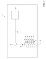
- Reference number 1 in figure 1 indicate a temperature detecting device according to the present invention.
- the temperature detecting device 1 comprises at least one optical probe 2 configured to detect a parameter indicative of a temperature; and at least one capsule 3 configured to define a camera 4 inside which the optical probe 2 is housed.
- the temperature detecting device 1 comprises a plurality of optical probes 2 and a plurality of capsules 3 and a main body 5 configured to support the plurality of capsules 3.
- the capsules 3 protrude from the main body 5.
- optical probes 2 of the plurality of optical probes and the capsules 3 of the plurality of capsules are identical one to the other.
- optical probes of the plurality of optical probes have different properties and/or dimensions and that the capsules of the plurality of capsules have, according to the features of the respective optical probes, different properties and/or shape.
- the main body 5 extends along a main axis A.
- the main body 5 supports the capsules 3 orthogonally to the main axis A.
- the capsules 3 can be supported by the main body 5 not orthogonally to the main axis A.
- the main body 5 is a hollow body shaped so as to define a main camera 6.
- the main body 5 is a cylindrical body and the main camera 6 is in communication with the cameras 4 of the capsules 3.
- the main body 5 is preferably made of the same material of the capsules 3.
- the main body 5 and the capsules 3 are preferably integral with one another.
- Each capsule 3 is made of refractory material, preferably is made of ceramic material.
- each capsule 3 is made of a material comprising alumina.
- each capsule 3 is defined by a body having a cylindrical or conical shape open at the end coupled to the main body 5 and closed at the opposite end with a dome-shaped element 8.
- Each optical probe 2 comprises at least one optical fiber 10 provided with a tip 11.
- each optical probe 2 is arranged inside the respective camera 4.
- each optical probe 2 is arranged inside the respective camera 4 so as the tip 11 of the fiber 10 is arranged substantially on the centre line of the camera 4.
- each optical probe 2 extends along the axis B of the respective capsule 3.
- the tip 11 is configured to collect the radiation in the camera 4.
- the optical fiber 10 is a sapphire optical fiber.
- the plurality of optical fibers 10 are connected, directly or indirectly, to a data acquisition unit 13, which communicates the detected data to a control system (not illustrated in the enclosed drawings).
- the data acquisition unit 13 is configured to calculate an average temperature on the basis of the radiations coming from the optical probes 2.
- the temperature detecting device 1 comprises a plurality of probes 2
- the detection of the temperature is more reliable as there are redundant probes and more accurate as the temperature is calculated as the average of the plurality of temperature detections.
- each fiber 10 is connected to a main optical fiber 14.
- the main optical fiber 14 is partially housed inside the main camera 6 of the main body 5 and is coupled to a connecting optical fiber 15 by means of an adapter 16.
- the adapter 16 is an optical connector configured to couple the main optical fiber 14 to the connecting optical fiber 15.
- Main optical fiber 14 and connecting optical fiber 15 have preferably different properties.
- the main optical fiber which normally runs in a hot environment, can be temperature resistant and therefore expensive, whereas the connecting optical fiber, which runs in a cold environment for a longer path can be of inferior quality and therefore cheaper than the main optical fiber.
- the connecting optical fiber 15 has one end coupled to the data acquisition unit 13 and the other end coupled to the main optical fiber 14, and in particular to the adapter 16.
- the main optical fiber 14 is a sapphire optical fiber
- the connecting optical fiber 15 has a silica based core and a silica based cladding.
- each capsule 3 acts as a black body.
- each capsule 3 absorbs the heat to which it is exposed and emits infra-red radiations in the camera 4 depending on the external temperature of the capsule 3.
- the IR radiations (schematically represented by the arrows in figure 2 ) emitted inside the camera 4 are indicative of the temperature outside the respective capsule 3.
- the optical probe 2 and in particular the tip 11, detects the IR radiation inside the respective camera 4.
- All the radiations detected by each optical probe 2 are sent to the data acquisition unit 13 as described before.
- the data acquisition unit 13 transforms the radiations into data.
- figure 3 is schematically represented a portion of a gas turbine power plant 20 according to the present invention.
- the gas turbine power plant comprises a compressor (not illustrated) at least one combustion chamber 21, a turbine 22 connected to the combustion chamber 21 and at least one temperature detecting device 1.
- the turbine 22 extends along a longitudinal axis C and comprises an expansion channel 24 and a plurality of stages 25 which are spaced along the longitudinal axis C; each stage 25 comprises fixed and rotating blades (not illustrated).
- the temperature detecting device 1 is arranged in the expansion channel 24 upstream the plurality of stages 25 wherein flows a hot gas flow along a main direction D (indicated by an arrow in figure 3 ).
- the temperature detecting device 1 faces upstream the hot gas flow.
- the temperature detecting device 1 is arranged so as each capsule 3 inside which is housed the respective optical probe 2 faces upstream the hot gas flow.
- the temperature detecting device 1 is positioned at the inlet of the turbine 22 so as each capsule 3 is positioned counter current with respect to the main direction of the hot gas flow flowing in the expansion channel of the turbine.
- the capsules 3 are orthogonal to the main body 5.
- the capsules 3 could also be arranged in various directions, along curved lines or following different flow angles within the hot gas flow.
- the temperature detecting device 1 is arranged inside the expansion channel 24 so as the main axis A of the main body 5 is arranged radially with respect to the longitudinal axis C of the gas turbine.
- the main body is not radially arranged.
- the temperature detecting device 1 is fixed to the stator casing of the gas turbine 22.
- a variant not shown provides that the temperature detecting device 1 is arranged at the outlet channel (not shown) of the combustion chamber 21.
Landscapes
- Physics & Mathematics (AREA)
- General Physics & Mathematics (AREA)
- Spectroscopy & Molecular Physics (AREA)
- Health & Medical Sciences (AREA)
- Life Sciences & Earth Sciences (AREA)
- Chemical & Material Sciences (AREA)
- Analytical Chemistry (AREA)
- Biochemistry (AREA)
- General Health & Medical Sciences (AREA)
- Immunology (AREA)
- Pathology (AREA)
- Radiation Pyrometers (AREA)
- Measuring Temperature Or Quantity Of Heat (AREA)
Description
- The present invention relates to a temperature detecting device for a gas turbine plant and to a gas turbine plant comprising said temperature detecting device.
- In known gas turbine power plants, temperature detecting devices are arranged at the outlet of the combustion chamber to control the temperature reached by the hot gases after the combustion.
- The temperature detecting devices used in these plants comprise thermocouples.
- However, thermocouples cannot withstand the temperature values reached in the gas turbine plant of the new generation. Thermocouples are made of alloys, for example Pt-Rh alloys, which melt at the operative temperature of the new gas turbine plant.
- An object of the present invention is therefore to provide a temperature detecting device for a gas turbine power plant that enables avoiding, or at least mitigating, the described drawbacks.
- In particular, it is an object of the present invention to provide a temperature detecting device for a gas turbine power plant reliably and, at the same time, sufficiently accurate.
- According to the present invention, there is provided a temperature detecting device for a gas turbine power plant comprising
- at least one optical probe configured to detect a parameter indicative of a temperature;
- at least one capsule configured to define a camera inside which the optical probe is housed.
- In this way the temperature detecting device is able to detect the temperature in gas turbine plants of the last generation. The capsule, in fact, is able to protect the sensing optical probe and, at the same time, to guarantee a good transmission of the temperature. The capsule, in fact, acts as a black body and emits inside the camera infra-red radiations depending on the temperature external to the capsule. The sensing optical probe detects the infra red radiations inside the camera.
- Advantageously the components of the sensing optical probe are completely immune from the most common disorder of factors that affect thermocouples, as for example Radio-Frequencies, Micro Waves, Electromagnetic Fields, Nuclear radiation, Light Radiations.
- Optical probes are also inherently safe because they are not current-carrying and therefore cannot generate sparks. They are non-flammable, resistant to chemicals, rust and corrosion.
- Moreover also the dimensions of the optical probes are often of small size.
- Optic systems for temperature measurement can also guarantee high accuracies (0.15° C) and measuring frequencies up to 1000 Hz ( i.e. a measurement every 0,02 seconds).
- Finally, optical probes for sensing temperature are long-term stable and retain their accuracy for many years. When required, recalibration is simple and fast.
- According to a preferred embodiment of the present invention, the optical probe comprises at least one optical fiber provided with a tip which is configured to collect the radiations inside the camera of the capsule; the capsule acting as a black body. In this way the Infra red radiation is detected by the tip of an optical fiber.
- According to a preferred embodiment of the present invention the capsule is made of refractory material, preferably of ceramic material. In this way the capsule is able to withstand high temperatures and at the same time to act as a black body. The ceramic material, in particular, has a very high-temperature resistance.
- According to a preferred embodiment of the present invention the device comprises a data acquisition unit coupled, directly or indirectly, to the optical fiber; the data acquisition unit being configured to transform the radiations collected by the optical fiber into temperature data. In this way the data acquired are collected in one single common unit.
- According to a preferred embodiment of the present invention the device comprises a plurality of optical probes and a plurality of capsules each of which is configured to define a camera inside which a respective optical probe is housed.
- In this way the temperature is detected by a plurality of sensing probes in order to improve the reliability of the detection.
- According to a preferred embodiment of the invention the plurality of capsules are arranged side by side. In this way the temperature is detected along a definite direction in order to detect the spatial temperature distribution at defined locations. This feature is particularly useful when the detecting device is positioned in the hot gas flow path of a turbine in a gas turbine power plant.
- According to a preferred embodiment of the invention each optical probe comprises at least one optical fiber provided with a tip; the plurality of optical fibers are coupled to a main optical fiber. The device comprising a data acquisition unit coupled, directly or indirectly, to the main optical fiber; the data acquisition unit being configured to transform the radiations collected by the main fiber into temperature data. In this way the data acquired by all the sensing probes are collected in one single common unit.
- According to a preferred embodiment of the invention the temperature detecting device comprises a connecting optical fiber which has one end coupled to the data acquisition unit and the other end coupled to the main optical fiber by means of an adapter configured to couple the main optical fiber to the connecting optical fiber.
- In this way, the connecting optical fiber and the main optical fiber can have different properties. For example, the main fiber, which normally runs in a hot environment, can be temperature resistant and therefore expensive, whereas the connecting optical fiber, which runs in a cold environment for a longer path can be of inferior quality and therefore cheaper than the main optical fiber.
- The adapter is therefore useful for connecting optical fibers having different properties.
- According to a preferred embodiment of the invention the temperature detecting device comprises a main body which is configured to support the plurality of capsules and is shaped so as to define a main camera which houses at least a portion of the main optical fiber; wherein the capsules protrudes perpendicularly from the main body.
- In this way the main body is a sort of "rake body" configured to support the capsules in a specific way which optimizes the temperature detection.
- It is another object of the present invention to provide a gas turbine power plant wherein the temperature is detected in a reliable and accurate way.
- According to the present invention, there is provided a gas turbine power plant comprising:
- a compressor
- at least one combustion chamber;
- a turbine extending along a longitudinal axis and connected to the at least one combustion chamber; the turbine comprising an expansion channel wherein a hot gas flow flows along a main direction; and
- at least one temperature detecting device comprising at least one optical probe configured to detect a parameter indicative of a temperature and at least one capsule configured to define a camera inside which the optical probe is housed.
- Thanks to the presence of an optical probe for detecting the temperature, the temperature is detected in a reliable and accurate way.
- According to a preferred embodiment of the present invention the temperature detecting device is arranged at the inlet of the turbine facing upstream the hot gas flow. Preferably, the temperature detecting device is arranged so as the capsule inside which is housed the optical probe faces upstream the hot gas flow. In other words, the temperature detecting device is positioned at the inlet of the turbine so as the capsule is positioned counter current with respect to the main direction of the hot gas flow flowing in the expansion channel of the turbine.
- According to a preferred embodiment of the present invention the turbine comprises a plurality of stages which are spaced along the longitudinal axis; each stage comprising fixed and rotating blades; the temperature detecting device being arranged in the expansion channel upstream the plurality of stages.
- In this way the temperature of the hot gases is detected at the beginning of the expansion channel.
- According to a preferred embodiment of the present invention the combustion chamber comprises an outlet channel; the temperature detecting device being arranged at the outlet channel facing upstream the hot gas flow.
- The present invention will now be described with reference to the accompanying drawings, which illustrate some non-limitative embodiment, in which:
-
Figure 1 is a schematic representation of the temperature detecting device according to the present invention; -
Figure 2 is a schematic representation of a detail of the temperature detecting device of thefigure 1 ; -
Figure 3 is a schematic representation of a portion of a power plant according to the present invention. - Reference number 1 in
figure 1 indicate a temperature detecting device according to the present invention. - The temperature detecting device 1 comprises at least one
optical probe 2 configured to detect a parameter indicative of a temperature; and at least onecapsule 3 configured to define acamera 4 inside which theoptical probe 2 is housed. - In the non limiting example herein described and illustrated, the temperature detecting device 1 comprises a plurality of
optical probes 2 and a plurality ofcapsules 3 and amain body 5 configured to support the plurality ofcapsules 3. Thecapsules 3 protrude from themain body 5. - Preferably the
optical probes 2 of the plurality of optical probes and thecapsules 3 of the plurality of capsules are identical one to the other. - A variant not shown provides that the optical probes of the plurality of optical probes have different properties and/or dimensions and that the capsules of the plurality of capsules have, according to the features of the respective optical probes, different properties and/or shape.
- With reference to
figure 1 andfigure 2 , themain body 5 extends along a main axis A. In the non limiting example herein described and illustrated, themain body 5 supports thecapsules 3 orthogonally to the main axis A. However, according to variants not shown thecapsules 3 can be supported by themain body 5 not orthogonally to the main axis A. - The
main body 5 is a hollow body shaped so as to define amain camera 6. - In the non limiting example here described and illustrated the
main body 5 is a cylindrical body and themain camera 6 is in communication with thecameras 4 of thecapsules 3. - The
main body 5 is preferably made of the same material of thecapsules 3. Themain body 5 and thecapsules 3 are preferably integral with one another. - Each
capsule 3 is made of refractory material, preferably is made of ceramic material. - In the non limiting example here described and illustrated each
capsule 3 is made of a material comprising alumina. - Preferably, each
capsule 3 is defined by a body having a cylindrical or conical shape open at the end coupled to themain body 5 and closed at the opposite end with a dome-shaped element 8. - Each
optical probe 2 comprises at least oneoptical fiber 10 provided with atip 11. - As hinted before, each
optical probe 2 is arranged inside therespective camera 4. - In particular, each
optical probe 2 is arranged inside therespective camera 4 so as thetip 11 of thefiber 10 is arranged substantially on the centre line of thecamera 4. - Preferably each
optical probe 2 extends along the axis B of therespective capsule 3. - The
tip 11 is configured to collect the radiation in thecamera 4. - Preferably, the
optical fiber 10 is a sapphire optical fiber. - The plurality of
optical fibers 10 are connected, directly or indirectly, to adata acquisition unit 13, which communicates the detected data to a control system (not illustrated in the enclosed drawings). - In particular, the
data acquisition unit 13 is configured to calculate an average temperature on the basis of the radiations coming from the optical probes 2. Advantageously, as the temperature detecting device 1 comprises a plurality ofprobes 2, the detection of the temperature is more reliable as there are redundant probes and more accurate as the temperature is calculated as the average of the plurality of temperature detections. - In the non limiting example here described and illustrated each
fiber 10 is connected to a mainoptical fiber 14. - The main
optical fiber 14 is partially housed inside themain camera 6 of themain body 5 and is coupled to a connectingoptical fiber 15 by means of anadapter 16. - The
adapter 16 is an optical connector configured to couple the mainoptical fiber 14 to the connectingoptical fiber 15. - Main
optical fiber 14 and connectingoptical fiber 15 have preferably different properties. - The main optical fiber, which normally runs in a hot environment, can be temperature resistant and therefore expensive, whereas the connecting optical fiber, which runs in a cold environment for a longer path can be of inferior quality and therefore cheaper than the main optical fiber. The connecting
optical fiber 15 has one end coupled to thedata acquisition unit 13 and the other end coupled to the mainoptical fiber 14, and in particular to theadapter 16. - Preferably, the main
optical fiber 14 is a sapphire optical fiber, while the connectingoptical fiber 15 has a silica based core and a silica based cladding. - In use, each
capsule 3 acts as a black body. - In other words each
capsule 3 absorbs the heat to which it is exposed and emits infra-red radiations in thecamera 4 depending on the external temperature of thecapsule 3. - In this way the IR radiations (schematically represented by the arrows in
figure 2 ) emitted inside thecamera 4 are indicative of the temperature outside therespective capsule 3. - The
optical probe 2, and in particular thetip 11, detects the IR radiation inside therespective camera 4. - All the radiations detected by each
optical probe 2 are sent to thedata acquisition unit 13 as described before. Thedata acquisition unit 13 transforms the radiations into data. - In
figure 3 is schematically represented a portion of a gasturbine power plant 20 according to the present invention. - The gas turbine power plant comprises a compressor (not illustrated) at least one
combustion chamber 21, aturbine 22 connected to thecombustion chamber 21 and at least one temperature detecting device 1. - The
turbine 22 extends along a longitudinal axis C and comprises anexpansion channel 24 and a plurality ofstages 25 which are spaced along the longitudinal axis C; eachstage 25 comprises fixed and rotating blades (not illustrated). - In the embodiment illustrated in
figure 3 the temperature detecting device 1 is arranged in theexpansion channel 24 upstream the plurality ofstages 25 wherein flows a hot gas flow along a main direction D (indicated by an arrow infigure 3 ). - In particular, the temperature detecting device 1 faces upstream the hot gas flow.
- Preferably, the temperature detecting device 1 is arranged so as each
capsule 3 inside which is housed the respectiveoptical probe 2 faces upstream the hot gas flow. - In other words, the temperature detecting device 1 is positioned at the inlet of the
turbine 22 so as eachcapsule 3 is positioned counter current with respect to the main direction of the hot gas flow flowing in the expansion channel of the turbine. - In the non limiting example here described and illustrated, the
capsules 3 are orthogonal to themain body 5. However, thecapsules 3 could also be arranged in various directions, along curved lines or following different flow angles within the hot gas flow. - In the non limiting example here described and illustrated, the temperature detecting device 1 is arranged inside the
expansion channel 24 so as the main axis A of themain body 5 is arranged radially with respect to the longitudinal axis C of the gas turbine. However variants not shown provide that the main body is not radially arranged. - Preferably the temperature detecting device 1 is fixed to the stator casing of the
gas turbine 22. - A variant not shown provides that the temperature detecting device 1 is arranged at the outlet channel (not shown) of the
combustion chamber 21. - Finally, it is clear that modifications and variants can be made to the device and the plant described herein without departing from the scope of the present invention, as defined in the appended claims.
Claims (15)
- Temperature detecting device for a gas turbine power plant (20) comprising:• at least one optical probe (2) configured to detect a parameter indicative of a temperature;• at least one capsule (3) configured to define a camera (4) inside which the optical probe (2) is housed.
- Device according to claim 1, wherein the optical probe (2) comprises at least one optical fiber (10) provided with a tip (11) which is configured to collect the radiations inside the camera (4) of the capsule (3); the capsule (3) acting as a black body.
- Device according to claim 1 or 2, wherein the capsule (3) is made of refractory material, preferably of ceramic material.
- Device according to claim 2 or 3, comprising a data acquisition unit (13) coupled, directly or indirectly, to the optical fiber (10); the data acquisition unit (13) being configured to transform the radiations collected by the optical fiber (10) into temperature data.
- Device according to anyone of the claims from 1 to 4, comprising a plurality of optical probes (2) and a plurality of capsules (3) each of which is configured to define a camera (4) inside which a respective optical probe (2) is housed.
- Device according to claim 5, wherein the plurality of capsules (3) are arranged side by side.
- Device according to claim 5 or 6, wherein each optical probe (2) comprises at least one optical fiber (10) provided with a tip (11); the plurality of optical fibers (10) being coupled to a main optical fiber (14).
- Device according to claim 7, comprising a data acquisition unit (13) coupled, directly or indirectly, to the main optical fiber (14); the data acquisition unit (13) being configured to transform the radiations collected by the main optical fiber (14) into temperature data.
- Device according to claim 8, comprising a connecting optical fiber (15) which has one end coupled to the data acquisition unit (13) and the other end coupled to the main optical fiber (14).
- Device according to claim 9, comprising an adapter (16) configured to couple the main optical fiber (14) to the connecting optical fiber (15).
- Device according to anyone of claims from 7 to 10, comprising a main body (5) which is configured to support the plurality of capsules (3) and is shaped so as to define a main camera (6) which houses at least a portion of the main optical fiber (14).
- Gas turbine power plant comprising:- a compressor- at least one combustion chamber (21);- a turbine (22) extending along a longitudinal axis (C) and connected to the at least one combustion chamber (21); the turbine (22) comprising an expansion channel (24) wherein a hot gas flow flows along a main direction (D); and- at least one temperature detecting device (1) as claimed in anyone of the foregoing claims.
- Gas turbine power plant according to claim 12, wherein the temperature detecting device (1) is arranged at the inlet of the gas turbine (22) facing upstream the hot gas flow.
- Gas turbine power plant according to claim 13, wherein the turbine comprises a plurality of stages (25) which are spaced along the longitudinal axis (C) in the expansion channel (24); each stage (25) comprising fixed and rotating blades; the temperature detecting device (1) being arranged in the expansion channel (24) upstream the plurality of stages (25).
- Gas turbine power plant according to claim 12, wherein the combustion chamber (21) comprises an outlet channel; the temperature detecting device (1) being arranged at the outlet channel facing upstream the hot gas flow.
Priority Applications (3)
| Application Number | Priority Date | Filing Date | Title |
|---|---|---|---|
| EP16183168.0A EP3282235B1 (en) | 2016-08-08 | 2016-08-08 | Gas turbine power plant comprising a temperature detecting device |
| US15/669,183 US10508954B2 (en) | 2016-08-08 | 2017-08-04 | Temperature detecting device for a gas turbine power plant and gas turbine power plant comprising said temperature detecting device |
| CN201710670942.4A CN107702817A (en) | 2016-08-08 | 2017-08-08 | Temperature-detecting device for combustion gas turbine power-equipment and the combustion gas turbine power-equipment including the temperature-detecting device |
Applications Claiming Priority (1)
| Application Number | Priority Date | Filing Date | Title |
|---|---|---|---|
| EP16183168.0A EP3282235B1 (en) | 2016-08-08 | 2016-08-08 | Gas turbine power plant comprising a temperature detecting device |
Publications (2)
| Publication Number | Publication Date |
|---|---|
| EP3282235A1 true EP3282235A1 (en) | 2018-02-14 |
| EP3282235B1 EP3282235B1 (en) | 2019-04-17 |
Family
ID=56615883
Family Applications (1)
| Application Number | Title | Priority Date | Filing Date |
|---|---|---|---|
| EP16183168.0A Active EP3282235B1 (en) | 2016-08-08 | 2016-08-08 | Gas turbine power plant comprising a temperature detecting device |
Country Status (3)
| Country | Link |
|---|---|
| US (1) | US10508954B2 (en) |
| EP (1) | EP3282235B1 (en) |
| CN (1) | CN107702817A (en) |
Cited By (1)
| Publication number | Priority date | Publication date | Assignee | Title |
|---|---|---|---|---|
| EP4134643A1 (en) * | 2021-08-13 | 2023-02-15 | Pratt & Whitney Canada Corp. | Non-contact high temperature measurement system |
Families Citing this family (3)
| Publication number | Priority date | Publication date | Assignee | Title |
|---|---|---|---|---|
| CN108760813B (en) * | 2018-06-05 | 2020-09-25 | 哈尔滨工程大学 | A system and method for monitoring the health of gas turbine turbine blades based on temperature signals |
| CN110333433A (en) * | 2019-07-11 | 2019-10-15 | 广东金鉴实验室科技有限公司 | A kind of micro- heat distribution tester and test method |
| CN114993509A (en) * | 2022-05-23 | 2022-09-02 | 中国航发贵州黎阳航空动力有限公司 | Sapphire optical fiber high-temperature sensor packaging structure and packaging method |
Citations (7)
| Publication number | Priority date | Publication date | Assignee | Title |
|---|---|---|---|---|
| GB2149936A (en) * | 1983-11-18 | 1985-06-19 | Smiths Industries Plc | Fibre optic assembly made from at least three optic fibre bundles |
| US4770544A (en) * | 1985-11-15 | 1988-09-13 | General Electric Company | Temperature sensor |
| US5078507A (en) * | 1991-03-18 | 1992-01-07 | General Electric Company | Temperature sensor |
| US5615953A (en) * | 1994-07-25 | 1997-04-01 | The Babcock & Wilcox Company | Boiler bank surface temperature profiler |
| EP0898158A2 (en) * | 1997-08-21 | 1999-02-24 | Abb Research Ltd. | Optical pyrometer for gas turbine |
| EP1835270A1 (en) * | 2006-03-15 | 2007-09-19 | Siemens Aktiengesellschaft | Temperature sensor for a turbine |
| WO2009135814A1 (en) * | 2008-05-07 | 2009-11-12 | Siemens Aktiengesellschaft | Temperature measurement at parts of a fluid kinetic machine |
Family Cites Families (16)
| Publication number | Priority date | Publication date | Assignee | Title |
|---|---|---|---|---|
| US1506487A (en) * | 1922-09-14 | 1924-08-26 | Hutchings Eric William | Means for locking electric-light-globe attachments to holders |
| US3137134A (en) * | 1959-07-16 | 1964-06-16 | Alsthom Cgee | Combined gas-steam cycle installations for boilers incorporating pressurised furnaces |
| US4708474A (en) * | 1985-11-14 | 1987-11-24 | United Technologies Corporation | Reflection corrected radiosity optical pyrometer |
| US5364186A (en) * | 1992-04-28 | 1994-11-15 | Luxtron Corporation | Apparatus and method for monitoring a temperature using a thermally fused composite ceramic blackbody temperature probe |
| US6698920B1 (en) * | 2000-05-08 | 2004-03-02 | General Electric Company | Temperature measuring system and optical switch used therein |
| AU2003304435A1 (en) * | 2002-11-21 | 2005-03-07 | Trustees Of Boston University | Fiber optic temperature sensor |
| US20090123109A1 (en) * | 2007-11-09 | 2009-05-14 | Lxdata Inc | Temperature sensor using an optical fiber |
| US8306373B2 (en) * | 2009-05-15 | 2012-11-06 | General Electric Company | Fiber Bragg grating sensing package and system for gas turbine temperature measurement |
| FR2953557B1 (en) * | 2009-12-07 | 2012-03-02 | Ge Energy Products France Snc | METHOD FOR DETECTING LIQUID FUEL LEAKAGE IN GAS TURBINE |
| US20120297792A1 (en) * | 2011-05-27 | 2012-11-29 | General Electric Company | Thermocouple well for a turbomachine |
| US9863813B2 (en) * | 2012-04-13 | 2018-01-09 | General Electric Company | Flame sensor |
| US9188493B2 (en) * | 2012-08-28 | 2015-11-17 | Nippon Steel & Sumitomo Metal Corporation | Method and apparatus for measuring surface temperature of cast slab |
| JP5975108B2 (en) * | 2012-10-26 | 2016-08-23 | 富士通株式会社 | Temperature measurement system and abnormality detection method |
| CN103674321B (en) * | 2013-12-20 | 2016-05-18 | 陕西电器研究所 | A kind of probe temperature-sensitive blackbody chamber for sapphire fiber temperature sensor |
| CN104534474B (en) * | 2014-12-08 | 2018-02-09 | 北京华清燃气轮机与煤气化联合循环工程技术有限公司 | A kind of gas turbine and the method for application gas turbine detection tempering |
| JP6712845B2 (en) * | 2015-09-10 | 2020-06-24 | 三菱日立パワーシステムズ株式会社 | Optical fiber probe, optical fiber measuring device and clearance control system |
-
2016
- 2016-08-08 EP EP16183168.0A patent/EP3282235B1/en active Active
-
2017
- 2017-08-04 US US15/669,183 patent/US10508954B2/en active Active
- 2017-08-08 CN CN201710670942.4A patent/CN107702817A/en active Pending
Patent Citations (7)
| Publication number | Priority date | Publication date | Assignee | Title |
|---|---|---|---|---|
| GB2149936A (en) * | 1983-11-18 | 1985-06-19 | Smiths Industries Plc | Fibre optic assembly made from at least three optic fibre bundles |
| US4770544A (en) * | 1985-11-15 | 1988-09-13 | General Electric Company | Temperature sensor |
| US5078507A (en) * | 1991-03-18 | 1992-01-07 | General Electric Company | Temperature sensor |
| US5615953A (en) * | 1994-07-25 | 1997-04-01 | The Babcock & Wilcox Company | Boiler bank surface temperature profiler |
| EP0898158A2 (en) * | 1997-08-21 | 1999-02-24 | Abb Research Ltd. | Optical pyrometer for gas turbine |
| EP1835270A1 (en) * | 2006-03-15 | 2007-09-19 | Siemens Aktiengesellschaft | Temperature sensor for a turbine |
| WO2009135814A1 (en) * | 2008-05-07 | 2009-11-12 | Siemens Aktiengesellschaft | Temperature measurement at parts of a fluid kinetic machine |
Cited By (1)
| Publication number | Priority date | Publication date | Assignee | Title |
|---|---|---|---|---|
| EP4134643A1 (en) * | 2021-08-13 | 2023-02-15 | Pratt & Whitney Canada Corp. | Non-contact high temperature measurement system |
Also Published As
| Publication number | Publication date |
|---|---|
| US20180038736A1 (en) | 2018-02-08 |
| EP3282235B1 (en) | 2019-04-17 |
| CN107702817A (en) | 2018-02-16 |
| US10508954B2 (en) | 2019-12-17 |
Similar Documents
| Publication | Publication Date | Title |
|---|---|---|
| US10508954B2 (en) | Temperature detecting device for a gas turbine power plant and gas turbine power plant comprising said temperature detecting device | |
| CN101886955B (en) | Fiber Bragg grating sensing package and system for gas turbine temperature measurement | |
| CN107796524B (en) | Temperature probe | |
| CN207197693U (en) | Pipeline outer wall temperature measuring equipment is used in a kind of heat fatigue monitoring | |
| Allil et al. | FBG-based sensor applied to flow rate measurements | |
| CN110361087B (en) | Feedback type actively-cooled high-temperature optical fiber blade tip timing sensor | |
| EP3721449B1 (en) | Heat pipe assembly of nuclear apparatus having fiber optical temperature detection system | |
| US5979220A (en) | In-situ sensors for gas turbines | |
| JP2013140150A (en) | Methods and apparatuses for monitoring nuclear reactor core conditions | |
| CN104583738A (en) | System for Remote Vibration Monitoring of Combustor Baskets and Transition Sections of Gas Turbines | |
| KR20120046992A (en) | An infrared fiber-optic probe for measuring the temperature of coolant system of nuclear power plant and the temperature measurement system using the same | |
| CN204064511U (en) | Based on online flue gas temperature measuring equipment and the system of visible ray technology | |
| CN101920299A (en) | Steel pipe end induction heating device with temperature detection system | |
| JP6511928B2 (en) | Measuring device and combustion furnace equipment | |
| JP4940191B2 (en) | Steam generator | |
| CN110296771A (en) | A kind of high-temperature flue gas thermometric water-cooled protecting device | |
| CN202614004U (en) | Cooling water leakage and blockage detecting device of heating furnace | |
| CN105444920B (en) | Online flue gas temp measuring method based on visible light technology, device and system | |
| CN106225860B (en) | Ultrasonic flue gas flowmeter | |
| US6527440B1 (en) | Optical power generator system condition status indicator and methods of indicating same | |
| Frank et al. | Application of a high resolution turbine pyrometer to heavy duty gas turbines | |
| JPH01176922A (en) | Exhaust gas temperature detecting device for gas turbine | |
| US20130098479A1 (en) | Gas Extractor for Exhaust Gas Monitoring | |
| JP2011515671A (en) | Optical measuring device and turbine | |
| RU152830U1 (en) | DEVICE FOR OPTICAL MEASUREMENT OF TEMPERATURE OF COMBUSTION PRODUCTS |
Legal Events
| Date | Code | Title | Description |
|---|---|---|---|
| PUAI | Public reference made under article 153(3) epc to a published international application that has entered the european phase |
Free format text: ORIGINAL CODE: 0009012 |
|
| STAA | Information on the status of an ep patent application or granted ep patent |
Free format text: STATUS: THE APPLICATION HAS BEEN PUBLISHED |
|
| AK | Designated contracting states |
Kind code of ref document: A1 Designated state(s): AL AT BE BG CH CY CZ DE DK EE ES FI FR GB GR HR HU IE IS IT LI LT LU LV MC MK MT NL NO PL PT RO RS SE SI SK SM TR |
|
| AX | Request for extension of the european patent |
Extension state: BA ME |
|
| STAA | Information on the status of an ep patent application or granted ep patent |
Free format text: STATUS: REQUEST FOR EXAMINATION WAS MADE |
|
| 17P | Request for examination filed |
Effective date: 20180802 |
|
| RBV | Designated contracting states (corrected) |
Designated state(s): AL AT BE BG CH CY CZ DE DK EE ES FI FR GB GR HR HU IE IS IT LI LT LU LV MC MK MT NL NO PL PT RO RS SE SI SK SM TR |
|
| RIC1 | Information provided on ipc code assigned before grant |
Ipc: G01J 5/00 20060101ALI20180914BHEP Ipc: G01J 5/04 20060101ALI20180914BHEP Ipc: G01J 5/08 20060101AFI20180914BHEP |
|
| GRAP | Despatch of communication of intention to grant a patent |
Free format text: ORIGINAL CODE: EPIDOSNIGR1 |
|
| STAA | Information on the status of an ep patent application or granted ep patent |
Free format text: STATUS: GRANT OF PATENT IS INTENDED |
|
| INTG | Intention to grant announced |
Effective date: 20181106 |
|
| RIN1 | Information on inventor provided before grant (corrected) |
Inventor name: HAFFNER, KEN Inventor name: KOCER, GUELRU |
|
| GRAS | Grant fee paid |
Free format text: ORIGINAL CODE: EPIDOSNIGR3 |
|
| GRAA | (expected) grant |
Free format text: ORIGINAL CODE: 0009210 |
|
| STAA | Information on the status of an ep patent application or granted ep patent |
Free format text: STATUS: THE PATENT HAS BEEN GRANTED |
|
| AK | Designated contracting states |
Kind code of ref document: B1 Designated state(s): AL AT BE BG CH CY CZ DE DK EE ES FI FR GB GR HR HU IE IS IT LI LT LU LV MC MK MT NL NO PL PT RO RS SE SI SK SM TR |
|
| REG | Reference to a national code |
Ref country code: GB Ref legal event code: FG4D |
|
| REG | Reference to a national code |
Ref country code: CH Ref legal event code: EP |
|
| REG | Reference to a national code |
Ref country code: DE Ref legal event code: R096 Ref document number: 602016012464 Country of ref document: DE |
|
| REG | Reference to a national code |
Ref country code: AT Ref legal event code: REF Ref document number: 1122073 Country of ref document: AT Kind code of ref document: T Effective date: 20190515 Ref country code: IE Ref legal event code: FG4D |
|
| REG | Reference to a national code |
Ref country code: NL Ref legal event code: MP Effective date: 20190417 |
|
| REG | Reference to a national code |
Ref country code: LT Ref legal event code: MG4D |
|
| PG25 | Lapsed in a contracting state [announced via postgrant information from national office to epo] |
Ref country code: NL Free format text: LAPSE BECAUSE OF FAILURE TO SUBMIT A TRANSLATION OF THE DESCRIPTION OR TO PAY THE FEE WITHIN THE PRESCRIBED TIME-LIMIT Effective date: 20190417 |
|
| PG25 | Lapsed in a contracting state [announced via postgrant information from national office to epo] |
Ref country code: PT Free format text: LAPSE BECAUSE OF FAILURE TO SUBMIT A TRANSLATION OF THE DESCRIPTION OR TO PAY THE FEE WITHIN THE PRESCRIBED TIME-LIMIT Effective date: 20190817 Ref country code: ES Free format text: LAPSE BECAUSE OF FAILURE TO SUBMIT A TRANSLATION OF THE DESCRIPTION OR TO PAY THE FEE WITHIN THE PRESCRIBED TIME-LIMIT Effective date: 20190417 Ref country code: AL Free format text: LAPSE BECAUSE OF FAILURE TO SUBMIT A TRANSLATION OF THE DESCRIPTION OR TO PAY THE FEE WITHIN THE PRESCRIBED TIME-LIMIT Effective date: 20190417 Ref country code: LT Free format text: LAPSE BECAUSE OF FAILURE TO SUBMIT A TRANSLATION OF THE DESCRIPTION OR TO PAY THE FEE WITHIN THE PRESCRIBED TIME-LIMIT Effective date: 20190417 Ref country code: NO Free format text: LAPSE BECAUSE OF FAILURE TO SUBMIT A TRANSLATION OF THE DESCRIPTION OR TO PAY THE FEE WITHIN THE PRESCRIBED TIME-LIMIT Effective date: 20190717 Ref country code: FI Free format text: LAPSE BECAUSE OF FAILURE TO SUBMIT A TRANSLATION OF THE DESCRIPTION OR TO PAY THE FEE WITHIN THE PRESCRIBED TIME-LIMIT Effective date: 20190417 Ref country code: SE Free format text: LAPSE BECAUSE OF FAILURE TO SUBMIT A TRANSLATION OF THE DESCRIPTION OR TO PAY THE FEE WITHIN THE PRESCRIBED TIME-LIMIT Effective date: 20190417 Ref country code: HR Free format text: LAPSE BECAUSE OF FAILURE TO SUBMIT A TRANSLATION OF THE DESCRIPTION OR TO PAY THE FEE WITHIN THE PRESCRIBED TIME-LIMIT Effective date: 20190417 |
|
| PG25 | Lapsed in a contracting state [announced via postgrant information from national office to epo] |
Ref country code: LV Free format text: LAPSE BECAUSE OF FAILURE TO SUBMIT A TRANSLATION OF THE DESCRIPTION OR TO PAY THE FEE WITHIN THE PRESCRIBED TIME-LIMIT Effective date: 20190417 Ref country code: PL Free format text: LAPSE BECAUSE OF FAILURE TO SUBMIT A TRANSLATION OF THE DESCRIPTION OR TO PAY THE FEE WITHIN THE PRESCRIBED TIME-LIMIT Effective date: 20190417 Ref country code: BG Free format text: LAPSE BECAUSE OF FAILURE TO SUBMIT A TRANSLATION OF THE DESCRIPTION OR TO PAY THE FEE WITHIN THE PRESCRIBED TIME-LIMIT Effective date: 20190717 Ref country code: GR Free format text: LAPSE BECAUSE OF FAILURE TO SUBMIT A TRANSLATION OF THE DESCRIPTION OR TO PAY THE FEE WITHIN THE PRESCRIBED TIME-LIMIT Effective date: 20190718 Ref country code: RS Free format text: LAPSE BECAUSE OF FAILURE TO SUBMIT A TRANSLATION OF THE DESCRIPTION OR TO PAY THE FEE WITHIN THE PRESCRIBED TIME-LIMIT Effective date: 20190417 |
|
| REG | Reference to a national code |
Ref country code: AT Ref legal event code: MK05 Ref document number: 1122073 Country of ref document: AT Kind code of ref document: T Effective date: 20190417 |
|
| PG25 | Lapsed in a contracting state [announced via postgrant information from national office to epo] |
Ref country code: IS Free format text: LAPSE BECAUSE OF FAILURE TO SUBMIT A TRANSLATION OF THE DESCRIPTION OR TO PAY THE FEE WITHIN THE PRESCRIBED TIME-LIMIT Effective date: 20190817 |
|
| REG | Reference to a national code |
Ref country code: DE Ref legal event code: R097 Ref document number: 602016012464 Country of ref document: DE |
|
| PG25 | Lapsed in a contracting state [announced via postgrant information from national office to epo] |
Ref country code: AT Free format text: LAPSE BECAUSE OF FAILURE TO SUBMIT A TRANSLATION OF THE DESCRIPTION OR TO PAY THE FEE WITHIN THE PRESCRIBED TIME-LIMIT Effective date: 20190417 Ref country code: CZ Free format text: LAPSE BECAUSE OF FAILURE TO SUBMIT A TRANSLATION OF THE DESCRIPTION OR TO PAY THE FEE WITHIN THE PRESCRIBED TIME-LIMIT Effective date: 20190417 Ref country code: RO Free format text: LAPSE BECAUSE OF FAILURE TO SUBMIT A TRANSLATION OF THE DESCRIPTION OR TO PAY THE FEE WITHIN THE PRESCRIBED TIME-LIMIT Effective date: 20190417 Ref country code: EE Free format text: LAPSE BECAUSE OF FAILURE TO SUBMIT A TRANSLATION OF THE DESCRIPTION OR TO PAY THE FEE WITHIN THE PRESCRIBED TIME-LIMIT Effective date: 20190417 Ref country code: DK Free format text: LAPSE BECAUSE OF FAILURE TO SUBMIT A TRANSLATION OF THE DESCRIPTION OR TO PAY THE FEE WITHIN THE PRESCRIBED TIME-LIMIT Effective date: 20190417 Ref country code: SK Free format text: LAPSE BECAUSE OF FAILURE TO SUBMIT A TRANSLATION OF THE DESCRIPTION OR TO PAY THE FEE WITHIN THE PRESCRIBED TIME-LIMIT Effective date: 20190417 |
|
| PLBE | No opposition filed within time limit |
Free format text: ORIGINAL CODE: 0009261 |
|
| STAA | Information on the status of an ep patent application or granted ep patent |
Free format text: STATUS: NO OPPOSITION FILED WITHIN TIME LIMIT |
|
| PG25 | Lapsed in a contracting state [announced via postgrant information from national office to epo] |
Ref country code: IT Free format text: LAPSE BECAUSE OF FAILURE TO SUBMIT A TRANSLATION OF THE DESCRIPTION OR TO PAY THE FEE WITHIN THE PRESCRIBED TIME-LIMIT Effective date: 20190417 Ref country code: SM Free format text: LAPSE BECAUSE OF FAILURE TO SUBMIT A TRANSLATION OF THE DESCRIPTION OR TO PAY THE FEE WITHIN THE PRESCRIBED TIME-LIMIT Effective date: 20190417 |
|
| 26N | No opposition filed |
Effective date: 20200120 |
|
| PG25 | Lapsed in a contracting state [announced via postgrant information from national office to epo] |
Ref country code: TR Free format text: LAPSE BECAUSE OF FAILURE TO SUBMIT A TRANSLATION OF THE DESCRIPTION OR TO PAY THE FEE WITHIN THE PRESCRIBED TIME-LIMIT Effective date: 20190417 |
|
| PG25 | Lapsed in a contracting state [announced via postgrant information from national office to epo] |
Ref country code: MC Free format text: LAPSE BECAUSE OF FAILURE TO SUBMIT A TRANSLATION OF THE DESCRIPTION OR TO PAY THE FEE WITHIN THE PRESCRIBED TIME-LIMIT Effective date: 20190417 Ref country code: LU Free format text: LAPSE BECAUSE OF NON-PAYMENT OF DUE FEES Effective date: 20190808 Ref country code: SI Free format text: LAPSE BECAUSE OF FAILURE TO SUBMIT A TRANSLATION OF THE DESCRIPTION OR TO PAY THE FEE WITHIN THE PRESCRIBED TIME-LIMIT Effective date: 20190417 Ref country code: LI Free format text: LAPSE BECAUSE OF NON-PAYMENT OF DUE FEES Effective date: 20190831 Ref country code: CH Free format text: LAPSE BECAUSE OF NON-PAYMENT OF DUE FEES Effective date: 20190831 |
|
| REG | Reference to a national code |
Ref country code: BE Ref legal event code: MM Effective date: 20190831 |
|
| PG25 | Lapsed in a contracting state [announced via postgrant information from national office to epo] |
Ref country code: IE Free format text: LAPSE BECAUSE OF NON-PAYMENT OF DUE FEES Effective date: 20190808 Ref country code: FR Free format text: LAPSE BECAUSE OF NON-PAYMENT OF DUE FEES Effective date: 20190831 |
|
| PG25 | Lapsed in a contracting state [announced via postgrant information from national office to epo] |
Ref country code: BE Free format text: LAPSE BECAUSE OF NON-PAYMENT OF DUE FEES Effective date: 20190831 |
|
| GBPC | Gb: european patent ceased through non-payment of renewal fee |
Effective date: 20200808 |
|
| PG25 | Lapsed in a contracting state [announced via postgrant information from national office to epo] |
Ref country code: CY Free format text: LAPSE BECAUSE OF FAILURE TO SUBMIT A TRANSLATION OF THE DESCRIPTION OR TO PAY THE FEE WITHIN THE PRESCRIBED TIME-LIMIT Effective date: 20190417 |
|
| PG25 | Lapsed in a contracting state [announced via postgrant information from national office to epo] |
Ref country code: HU Free format text: LAPSE BECAUSE OF FAILURE TO SUBMIT A TRANSLATION OF THE DESCRIPTION OR TO PAY THE FEE WITHIN THE PRESCRIBED TIME-LIMIT; INVALID AB INITIO Effective date: 20160808 Ref country code: MT Free format text: LAPSE BECAUSE OF FAILURE TO SUBMIT A TRANSLATION OF THE DESCRIPTION OR TO PAY THE FEE WITHIN THE PRESCRIBED TIME-LIMIT Effective date: 20190417 |
|
| PG25 | Lapsed in a contracting state [announced via postgrant information from national office to epo] |
Ref country code: GB Free format text: LAPSE BECAUSE OF NON-PAYMENT OF DUE FEES Effective date: 20200808 |
|
| PG25 | Lapsed in a contracting state [announced via postgrant information from national office to epo] |
Ref country code: MK Free format text: LAPSE BECAUSE OF FAILURE TO SUBMIT A TRANSLATION OF THE DESCRIPTION OR TO PAY THE FEE WITHIN THE PRESCRIBED TIME-LIMIT Effective date: 20190417 |
|
| P01 | Opt-out of the competence of the unified patent court (upc) registered |
Effective date: 20240430 |
|
| PGFP | Annual fee paid to national office [announced via postgrant information from national office to epo] |
Ref country code: DE Payment date: 20250819 Year of fee payment: 10 |