EP3282211A1 - Air conditioning system and control method for same - Google Patents
Air conditioning system and control method for same Download PDFInfo
- Publication number
- EP3282211A1 EP3282211A1 EP16776529.6A EP16776529A EP3282211A1 EP 3282211 A1 EP3282211 A1 EP 3282211A1 EP 16776529 A EP16776529 A EP 16776529A EP 3282211 A1 EP3282211 A1 EP 3282211A1
- Authority
- EP
- European Patent Office
- Prior art keywords
- pipe
- refrigerant
- indoor
- air conditioning
- conditioning system
- Prior art date
- Legal status (The legal status is an assumption and is not a legal conclusion. Google has not performed a legal analysis and makes no representation as to the accuracy of the status listed.)
- Granted
Links
Images





Classifications
-
- F—MECHANICAL ENGINEERING; LIGHTING; HEATING; WEAPONS; BLASTING
- F25—REFRIGERATION OR COOLING; COMBINED HEATING AND REFRIGERATION SYSTEMS; HEAT PUMP SYSTEMS; MANUFACTURE OR STORAGE OF ICE; LIQUEFACTION SOLIDIFICATION OF GASES
- F25B—REFRIGERATION MACHINES, PLANTS OR SYSTEMS; COMBINED HEATING AND REFRIGERATION SYSTEMS; HEAT PUMP SYSTEMS
- F25B13/00—Compression machines, plants or systems, with reversible cycle
-
- F—MECHANICAL ENGINEERING; LIGHTING; HEATING; WEAPONS; BLASTING
- F25—REFRIGERATION OR COOLING; COMBINED HEATING AND REFRIGERATION SYSTEMS; HEAT PUMP SYSTEMS; MANUFACTURE OR STORAGE OF ICE; LIQUEFACTION SOLIDIFICATION OF GASES
- F25B—REFRIGERATION MACHINES, PLANTS OR SYSTEMS; COMBINED HEATING AND REFRIGERATION SYSTEMS; HEAT PUMP SYSTEMS
- F25B2313/00—Compression machines, plants or systems with reversible cycle not otherwise provided for
- F25B2313/003—Indoor unit with water as a heat sink or heat source
-
- F—MECHANICAL ENGINEERING; LIGHTING; HEATING; WEAPONS; BLASTING
- F25—REFRIGERATION OR COOLING; COMBINED HEATING AND REFRIGERATION SYSTEMS; HEAT PUMP SYSTEMS; MANUFACTURE OR STORAGE OF ICE; LIQUEFACTION SOLIDIFICATION OF GASES
- F25B—REFRIGERATION MACHINES, PLANTS OR SYSTEMS; COMBINED HEATING AND REFRIGERATION SYSTEMS; HEAT PUMP SYSTEMS
- F25B2313/00—Compression machines, plants or systems with reversible cycle not otherwise provided for
- F25B2313/007—Compression machines, plants or systems with reversible cycle not otherwise provided for three pipes connecting the outdoor side to the indoor side with multiple indoor units
-
- F—MECHANICAL ENGINEERING; LIGHTING; HEATING; WEAPONS; BLASTING
- F25—REFRIGERATION OR COOLING; COMBINED HEATING AND REFRIGERATION SYSTEMS; HEAT PUMP SYSTEMS; MANUFACTURE OR STORAGE OF ICE; LIQUEFACTION SOLIDIFICATION OF GASES
- F25B—REFRIGERATION MACHINES, PLANTS OR SYSTEMS; COMBINED HEATING AND REFRIGERATION SYSTEMS; HEAT PUMP SYSTEMS
- F25B2313/00—Compression machines, plants or systems with reversible cycle not otherwise provided for
- F25B2313/023—Compression machines, plants or systems with reversible cycle not otherwise provided for using multiple indoor units
- F25B2313/0231—Compression machines, plants or systems with reversible cycle not otherwise provided for using multiple indoor units with simultaneous cooling and heating
-
- F—MECHANICAL ENGINEERING; LIGHTING; HEATING; WEAPONS; BLASTING
- F25—REFRIGERATION OR COOLING; COMBINED HEATING AND REFRIGERATION SYSTEMS; HEAT PUMP SYSTEMS; MANUFACTURE OR STORAGE OF ICE; LIQUEFACTION SOLIDIFICATION OF GASES
- F25B—REFRIGERATION MACHINES, PLANTS OR SYSTEMS; COMBINED HEATING AND REFRIGERATION SYSTEMS; HEAT PUMP SYSTEMS
- F25B2313/00—Compression machines, plants or systems with reversible cycle not otherwise provided for
- F25B2313/023—Compression machines, plants or systems with reversible cycle not otherwise provided for using multiple indoor units
- F25B2313/0233—Compression machines, plants or systems with reversible cycle not otherwise provided for using multiple indoor units in parallel arrangements
- F25B2313/02331—Compression machines, plants or systems with reversible cycle not otherwise provided for using multiple indoor units in parallel arrangements during cooling
-
- F—MECHANICAL ENGINEERING; LIGHTING; HEATING; WEAPONS; BLASTING
- F25—REFRIGERATION OR COOLING; COMBINED HEATING AND REFRIGERATION SYSTEMS; HEAT PUMP SYSTEMS; MANUFACTURE OR STORAGE OF ICE; LIQUEFACTION SOLIDIFICATION OF GASES
- F25B—REFRIGERATION MACHINES, PLANTS OR SYSTEMS; COMBINED HEATING AND REFRIGERATION SYSTEMS; HEAT PUMP SYSTEMS
- F25B2313/00—Compression machines, plants or systems with reversible cycle not otherwise provided for
- F25B2313/023—Compression machines, plants or systems with reversible cycle not otherwise provided for using multiple indoor units
- F25B2313/0233—Compression machines, plants or systems with reversible cycle not otherwise provided for using multiple indoor units in parallel arrangements
- F25B2313/02334—Compression machines, plants or systems with reversible cycle not otherwise provided for using multiple indoor units in parallel arrangements during heating
-
- F—MECHANICAL ENGINEERING; LIGHTING; HEATING; WEAPONS; BLASTING
- F25—REFRIGERATION OR COOLING; COMBINED HEATING AND REFRIGERATION SYSTEMS; HEAT PUMP SYSTEMS; MANUFACTURE OR STORAGE OF ICE; LIQUEFACTION SOLIDIFICATION OF GASES
- F25B—REFRIGERATION MACHINES, PLANTS OR SYSTEMS; COMBINED HEATING AND REFRIGERATION SYSTEMS; HEAT PUMP SYSTEMS
- F25B2313/00—Compression machines, plants or systems with reversible cycle not otherwise provided for
- F25B2313/023—Compression machines, plants or systems with reversible cycle not otherwise provided for using multiple indoor units
- F25B2313/0234—Compression machines, plants or systems with reversible cycle not otherwise provided for using multiple indoor units in series arrangements
- F25B2313/02343—Compression machines, plants or systems with reversible cycle not otherwise provided for using multiple indoor units in series arrangements during dehumidification
-
- F—MECHANICAL ENGINEERING; LIGHTING; HEATING; WEAPONS; BLASTING
- F25—REFRIGERATION OR COOLING; COMBINED HEATING AND REFRIGERATION SYSTEMS; HEAT PUMP SYSTEMS; MANUFACTURE OR STORAGE OF ICE; LIQUEFACTION SOLIDIFICATION OF GASES
- F25B—REFRIGERATION MACHINES, PLANTS OR SYSTEMS; COMBINED HEATING AND REFRIGERATION SYSTEMS; HEAT PUMP SYSTEMS
- F25B2313/00—Compression machines, plants or systems with reversible cycle not otherwise provided for
- F25B2313/025—Compression machines, plants or systems with reversible cycle not otherwise provided for using multiple outdoor units
- F25B2313/0253—Compression machines, plants or systems with reversible cycle not otherwise provided for using multiple outdoor units in parallel arrangements
-
- F—MECHANICAL ENGINEERING; LIGHTING; HEATING; WEAPONS; BLASTING
- F25—REFRIGERATION OR COOLING; COMBINED HEATING AND REFRIGERATION SYSTEMS; HEAT PUMP SYSTEMS; MANUFACTURE OR STORAGE OF ICE; LIQUEFACTION SOLIDIFICATION OF GASES
- F25B—REFRIGERATION MACHINES, PLANTS OR SYSTEMS; COMBINED HEATING AND REFRIGERATION SYSTEMS; HEAT PUMP SYSTEMS
- F25B2313/00—Compression machines, plants or systems with reversible cycle not otherwise provided for
- F25B2313/027—Compression machines, plants or systems with reversible cycle not otherwise provided for characterised by the reversing means
- F25B2313/02742—Compression machines, plants or systems with reversible cycle not otherwise provided for characterised by the reversing means using two four-way valves
-
- F—MECHANICAL ENGINEERING; LIGHTING; HEATING; WEAPONS; BLASTING
- F25—REFRIGERATION OR COOLING; COMBINED HEATING AND REFRIGERATION SYSTEMS; HEAT PUMP SYSTEMS; MANUFACTURE OR STORAGE OF ICE; LIQUEFACTION SOLIDIFICATION OF GASES
- F25B—REFRIGERATION MACHINES, PLANTS OR SYSTEMS; COMBINED HEATING AND REFRIGERATION SYSTEMS; HEAT PUMP SYSTEMS
- F25B2400/00—Component parts or details not otherwise provided for in this subclass
- F25B2400/13—Economisers
Definitions
- the present invention relates to an air conditioning system and a control method of the same, and particularly an air conditioning system including an outdoor unit and an indoor dehumidification and heating unit and a control method of the same.
- Air conditioning systems equipped with a humidity control function have been created because in rainy and humid regions and in rainy seasons the humidity in the air becomes higher and is also uncomfortably felt by the human body.
- Air conditioning systems generally dehumidify air using the following principle. Moisture in the air is removed by causing the air to flow through a heat exchanger whose surface temperature is lower than the dewpoint of the air to thereby condense the air, and because of this dehumidification principle it is understood that the dehumidifying effect is better the lower the surface temperature of the heat exchanger is. However, although the humidity can be lowered when dehumidification is performed at a low temperature, the temperature of the air also concomitantly drops, so in an environment requiring both a dehumidifying effect and temperature, such as a bathroom, for example, it becomes necessary to maintain the comfort experienced by the human body by heating the air again after dehumidifying the air.
- an electric heating unit 29X is added downstream of an airflow path of a dehumidification heat exchanger 21 X.
- an electric heating unit ordinarily utilizes a heating element (e.g., a heating wire) to convert electrical energy to thermal energy and raises the blowing air temperature by causing the air to absorb a heat quantity when the air flows through it, so this ends up increasing energy consumption.
- a heating element e.g., a heating wire
- the heat quantity of the refrigerant in the same section is first used for heating and is then used for cooling after being carried away by the airflow, so both the dehumidification heat exchanger 21X1 and the heating heat exchanger 22X do not exhibit sufficient roles, dehumidification is no longer sufficient, and the heating quantity also becomes deficient.
- air conditioning systems have a hot water supply function.
- the present invention has been completed in view of the problems described above, and it is an object thereof to provide an air conditioning system including an outdoor unit and an indoor dehumidification and heating unit and a control method of the same.
- the air conditioning system can provide a sufficiently dehumidified and heated fluid in an energy conserving way to a room and furthermore has a hot water supply function.
- the present invention provides an air conditioning system including an outdoor unit and an indoor dehumidification and heating unit that are coupled to each other via coupling pipes.
- a discharge side of a compressor is coupled to one end of a discharge pipe, another end of the discharge pipe is coupled to one end of a first coupling pipe of the coupling pipes, a suction side of the compressor is coupled to one end of a suction pipe, another end of the suction pipe is coupled to one end of a second coupling pipe of the coupling pipes, and an outdoor-side heat exchanger is provided in a section of the first coupling pipe positioned inside the outdoor unit.
- a first indoor-side refrigerant regulating device and a first heat exchanger are provided in a first indoor-side pipe sequentially from one end of the first indoor-side pipe, the one end of the first indoor-side pipe is coupled to a section of the first coupling pipe positioned outside the outdoor unit, and another end of the first indoor-side pipe is coupled to a section of the second coupling pipe positioned outside the outdoor unit.
- a heat cycle device for delivering a heat quantity or a cold quantity of the indoor dehumidification and heating unit to a room is also provided in the indoor dehumidification and heating unit.
- the coupling pipes further include a third coupling pipe having one end coupled to the discharge pipe.
- a second indoor-side refrigerant regulating device and a second heat exchanger are provided in a second indoor-side pipe sequentially from one end of the second indoor-side pipe, the one end of the second indoor-side pipe is coupled to the first indoor-side pipe and is positioned between the first indoor-side refrigerant regulating device and the one end of the first indoor-side pipe, and another end of the second indoor-side pipe is coupled to a section of the third coupling pipe positioned outside the outdoor unit.
- the air conditioning system further includes a refrigerant-water heat exchange unit including a refrigerant pipe, a water circuit configured by a water pipe, and a refrigerant-water heat exchanger that exchanges heat between refrigerant flowing in the refrigerant pipe and water flowing in the water pipe, with one end of the refrigerant pipe being coupled to the section of the first coupling pipe positioned outside the outdoor unit and with another end of the refrigerant pipe being coupled to the section of the third coupling pipe positioned outside the outdoor unit.
- a refrigerant-water heat exchange unit including a refrigerant pipe, a water circuit configured by a water pipe, and a refrigerant-water heat exchanger that exchanges heat between refrigerant flowing in the refrigerant pipe and water flowing in the water pipe, with one end of the refrigerant pipe being coupled to the section of the first coupling pipe positioned outside the outdoor unit and with another end of the refrigerant pipe being coupled to the section of the third coupling pipe positioned outside the outdoor
- the air conditioning system can operate in a hot water supply/dehumidification/heating mode or a dehumidification/heating-only mode, and in these two modes the first heat exchanger of the indoor dehumidification and heating unit can be utilized to dehumidify the fluid delivered from the heat cycle device and the second heat exchanger of the indoor dehumidification and heating unit can be utilized to heat the fluid delivered from the heat cycle device.
- the air conditioning system of the present invention can reduce energy consumption and can enhance the comfort experienced by persons in the room by ensuring that the temperature distribution of the fluid that the indoor dehumidification and heating unit supplies to the room does not become uneven.
- the air conditioning system of the present invention can ensure that the dehumidification does not become insufficient and the heating quantity is not deficient because both the dehumidification heat exchanger (i.e., the first heat exchanger) and the heating heat exchanger (i.e., the second heat exchanger) can fulfill sufficient roles.
- waste heat utilization can be realized by using in the second heat exchanger some of the waste heat that is discharged from the outdoor unit to the atmosphere anyway, so the energy consumption rate can be improved to realize energy conservation and environmental protection.
- the air conditioning system of the present invention can perform a constant-temperature defrost operation in the hot water supply/dehumidification/heating mode or the dehumidification/heating-only mode, which is to say that because the heating heat exchanger fulfills a heating action in the hot water supply/dehumidification/heating mode or the dehumidification/heating-only mode, cold air does not blow to the room even if an indoor blower device continues to be operated, so constant-temperature defrosting can be realized.
- the air conditioning system includes the refrigerant-water heat exchange unit including the refrigerant pipe, the water circuit configured by the water pipe, and the refrigerant-water heat exchanger that exchanges heat between the refrigerant flowing in the refrigerant pipe and the water flowing in the water pipe, so by utilizing the refrigerant carried from the outdoor unit and flowing in the refrigerant pipe to heat the water flowing in the water pipe of the water circuit, the water circuit can be utilized to provide hot water.
- the outdoor unit further includes a first switching device that can switch between a first switching state and a second switching state.
- a first switching device that can switch between a first switching state and a second switching state.
- the first switching state of the first switching device the first coupling pipe and the discharge pipe communicate with each other and the second coupling pipe and the suction pipe communicate with each other
- the second switching state of the first switching device the first coupling pipe and the suction pipe communicate with each other and the second coupling pipe and the discharge pipe communicate with each other.
- the air conditioning system can operate in a hot water supply/dehumidification/heating mode, a dehumidification/heating-only mode, a heating/hot water supply mode, and a hot water supply-only mode.
- the first switching state of the outdoor unit can be switched to the second switching state to thereby cause both the first heat exchanger and the second heat exchanger to fulfill roles as condensers to heat the fluid delivered from the heat cycle device. For this reason, overall efficiency can be enhanced.
- the outdoor unit is further provided with a first outdoor-side branching pipe having one end coupled to the suction pipe
- the third coupling pipe has a first section and a second section, with the first section being coupled to the discharge pipe and with the second section being coupled to the second indoor-side pipe
- the air conditioning system further includes a second switching device that can switch between a first switching state and a second switching state.
- the second switching device In the first switching state of the second switching device the second section of the third coupling pipe and the first section of the third coupling pipe communicate with each other, and in the second switching state of the second switching device the second section of the third coupling pipe and another end of the first outdoor-side branching pipe communicate with each other.
- the air conditioning system can operate in a hot water supply/dehumidification/heating mode, a dehumidification/heating-only mode, a heating/hot water supply mode, a hot water supply-only mode, and a cooling-only mode.
- the first switching device can be switched to the first switching state and the second switching device can be switched to the second switching state to thereby cause both the first heat exchanger and the second heat exchanger to fulfill roles as evaporators to cool the room air. For this reason, overall efficiency can be enhanced.
- the air conditioning system can perform a routine defrost operation in the cooling-only mode.
- the operation of the heat cycle device is stopped to ensure that the drop in the room temperature does not affect the comfort experienced by persons in the room, but the heat cycle device is not limited to this and can also be operated at a low speed to provide a weak airflow to the room.
- the defrost speed of the routine defrost operation performed in the cooling-only mode is faster.
- the first switching device is a four-port valve.
- the first indoor-side refrigerant regulating device and the second indoor-side refrigerant regulating device are motor-operated valves or electromagnetic valves.
- the heat cycle device is an indoor blower device, and the first heat exchanger and the second heat exchanger are provided in a flow path of an airflow formed by the indoor blower device.
- the first heat exchanger is provided on an upstream side or a downstream side of the second heat exchanger in the flow path or the first heat exchanger and the second heat exchanger are provided side by side in the flow path.
- a reservoir device is provided in the suction pipe.
- the reservoir device can be utilized to absorb the liquid component in the refrigerant returned to the compressor, so that the compressor does not suck in liquid refrigerant and sustain damage.
- the air conditioning system further includes a floor heating water circuit connected to the water circuit.
- the refrigerant-water heat exchange unit can be utilized to heat floorboards or the like.
- the air conditioning system further includes a water tank provided with a domestic water pipe connected to a terminal end of domestic water, and the water pipe configuring the water circuit runs through the water tank.
- the refrigerant-water heat exchange unit can be utilized to heat floorboards or the like and provide hot water to the terminal end of domestic water.
- the air conditioning system of the present invention preferably there is an electric heating device in the water tank.
- the electric heating device can be utilized to heat the water in the water tank and thereby provide water with the necessary temperature to the terminal end of domestic water.
- the air conditioning system further includes a fan coil unit connected to the water circuit.
- the refrigerant-water heat exchange unit can be utilized to heat or cool the water flowing in the water circuit to thereby provide the heat quantity or cold quantity of the water in the water circuit to the fan coil unit, and the fan coil unit can be utilized to heat or cool.
- the outdoor unit further includes a sub-cooling pipe, a refrigerant regulating device, and a sub-cooler
- one end of the sub-cooling pipe is coupled to the first coupling pipe in a position located on the side of the outdoor heat exchanger corresponding to another end of the first coupling pipe
- another end of the sub-cooling pipe is coupled to the suction pipe
- the refrigerant regulating device is provided in the sub-cooling pipe
- the sub-cooler exchanges heat between refrigerant flowing in the first coupling pipe and refrigerant that has flowed through the refrigerant regulating device in the sub-cooling pipe.
- the sub-cooler can be utilized to cool the refrigerant flowing in the first outdoor-side pipe, whereby the capacity to dehumidify the fluid delivered from the heat cycle device utilizing the first heat exchanger of the indoor dehumidification and heating unit can be enhanced.
- the air conditioning system further includes at least one indoor unit, the indoor unit includes an indoor unit-side refrigerant pipe, one end of the indoor unit-side refrigerant pipe is coupled to the section of the first coupling pipe positioned outside the outdoor unit, another end of the indoor unit-side refrigerant pipe is coupled to the section of the second coupling pipe positioned outside the outdoor unit, and an indoor unit-side refrigerant regulating device and an indoor unit-side heat exchanger are provided in the indoor unit-side refrigerant pipe sequentially from the one end of the indoor unit-side refrigerant pipe.
- the indoor unit includes an indoor unit-side refrigerant pipe, one end of the indoor unit-side refrigerant pipe is coupled to the section of the first coupling pipe positioned outside the outdoor unit, another end of the indoor unit-side refrigerant pipe is coupled to the section of the second coupling pipe positioned outside the outdoor unit, and an indoor unit-side refrigerant regulating device and an indoor unit-side heat exchanger are provided in the indoor unit-side refriger
- the indoor dehumidification and heating unit be utilized to perform dehumidification and heating, but the refrigerant-water heat exchange unit can be utilized to provide hot water, and cooling by the indoor unit can also be done.
- the air conditioning system includes a plurality of the outdoor units, outdoor unit coupling pipe spans of the first coupling pipe that are coupled to the plural outdoor units merge with a total coupling pipe span of the first coupling pipe outside the outdoor units, the one end of the first indoor-side pipe and the one end of the refrigerant pipe of the refrigerant-water heat exchange unit are coupled to the total coupling pipe span of the first coupling pipe, outdoor unit coupling pipe spans of the second coupling pipe that are coupled to the plural outdoor units merge with a total coupling pipe span of the second coupling pipe outside the outdoor units, the other end of the first indoor-side pipe is coupled to the total coupling pipe span of the second coupling pipe, and outdoor unit coupling pipe spans of the third coupling pipe that are coupled to the plural outdoor units merge with a total coupling pipe span of the third coupling pipe outside the outdoor units, and the other end of the second indoor-side pipe and the other end of the refrigerant pipe are coupled to the total coupling pipe span
- a refrigerant-water heat exchange unit-side refrigerant regulating device is provided between the one end of the refrigerant pipe and the refrigerant-water heat exchanger.
- the flow rate and state of the refrigerant flowing in the refrigerant pipe can be controlled.
- the refrigerant-water heat exchange unit-side refrigerant regulating device is a motor-operated valve or an electromagnetic valve.
- an electromagnetic valve is provided between the other end of the refrigerant pipe and the refrigerant-water heat exchanger.
- the electromagnetic valve is provided between the other end of the refrigerant pipe and the refrigerant-water heat exchanger, so even when the temperature of the refrigerant flowing from the third coupling pipe to the refrigerant-water heat exchange unit is too low, the electromagnetic valve can be closed to ensure that freezing does not occur as a result of the temperature of the refrigerant in the refrigerant pipe being too low.
- a refrigerant control valve is provided in the second coupling pipe.
- the refrigerant accumulating in the indoor dehumidification and heating unit can be effectively reduced, whereby the refrigerant flowing in the refrigerant-water heat exchange unit can be increased, so that the heating capacity of the refrigerant in the refrigerant-water heat exchange unit with respect to the water can be enhanced.
- the refrigerant control valve is any one type among a motor-operated valve, an electromagnetic valve, or a pilot valve.
- the refrigerant control valve can be inexpensively configured.
- the second switching device is provided in the outdoor unit.
- the second switching device is integrated into the outdoor unit, which is useful for making compact and downsizing the structure of the air conditioning system.
- the present invention provides an air conditioning system control method that is used to control the above-described air conditioning system, wherein a refrigerant-water heat exchange unit-side refrigerant regulating device is provided between the one end of the refrigerant pipe and the refrigerant-water heat exchanger.
- the air conditioning system control method utilizes a control unit to cause the air conditioning system to switch operation between a first mode, a second mode, and a third mode, in the first mode the first switching device is switched to the second switching state and the second switching device is switched to the first switching state, in the second mode the first switching device is switched to the first switching state, the second switching device is switched to the first switching state, and the first indoor-side refrigerant regulating device and the second indoor-side refrigerant regulating device are opened, and in the third mode the first switching device is switched to the first switching state and the second switching device is switched to the second switching state.
- the air conditioning system preferably in the second mode the air conditioning system performs a defrost operation.
- the first indoor-side refrigerant regulating device and the second indoor-side refrigerant regulating device are opened and operation of the heat cycle device is stopped or the heat cycle device is operated at a low speed to thereby perform a defrost operation.
- the air conditioning system control method pertaining to the present invention preferably in the first mode or the third mode the first indoor-side refrigerant regulating device, the second indoor-side refrigerant regulating device, and the refrigerant-water heat exchange unit-side refrigerant regulating device are opened.
- the first indoor-side refrigerant regulating device and the second indoor-side refrigerant regulating device are partially opened and the refrigerant-water heat exchange unit-side refrigerant regulating device is opened.
- the first indoor-side refrigerant regulating device and the second indoor-side refrigerant regulating device are opened and the refrigerant-water heat exchange unit-side refrigerant regulating device is closed.
- a refrigerant control valve is provided in the second coupling pipe, and in the first mode the refrigerant control valve is closed, the first indoor-side refrigerant regulating device and the second indoor-side refrigerant regulating device are partially opened, and the refrigerant-water heat exchange unit-side refrigerant regulating device is opened.
- the refrigerant control valve is any one type among a motor-operated valve, an electromagnetic valve, or a pilot valve.
- the air conditioning system can operate in a hot water supply/dehumidification/heating mode or a dehumidification/heating-only mode, and in these two modes the first heat exchanger of the indoor dehumidification and heating unit can be utilized to dehumidify the fluid delivered from the heat cycle device and the second heat exchanger of the indoor dehumidification and heating unit can be utilized to heat the fluid delivered from the heat cycle device.
- the air conditioning system of the present invention can reduce energy consumption and can enhance the comfort experienced by persons in the room by ensuring that the temperature distribution of the fluid that the indoor dehumidification and heating unit supplies to the room does not become uneven. Furthermore, compared to a structure where the first heat exchanger and the second heat exchanger connected in series in the indoor refrigerant circuit are sequentially provided in the flow path formed by the heat cycle device, the air conditioning system of the present invention can ensure that the dehumidification does not become insufficient and the heating quantity is not deficient because both the first heat exchanger and the second heat exchanger can fulfill sufficient roles. Furthermore, waste heat utilization can be realized by using in the second heat exchanger some of the waste heat that is discharged from the outdoor unit to the atmosphere anyway, so the energy consumption rate can be improved to realize energy conservation and environmental protection.
- the air conditioning system can perform a constant-temperature defrost operation in the hot water supply/dehumidification/heating mode or the dehumidification/heating-only mode, which is to say that because the heating heat exchanger effects a heating action in the hot water supply/dehumidification/heating mode or the dehumidification/heating-only mode, cold air does not blow to the room even when an indoor blower device continues to be operated, so constant-temperature defrosting can be realized.
- the water circuit can be utilized to provide hot water.
- the air conditioning system 1 of the present embodiment includes an outdoor unit 100, an indoor dehumidification and heating unit 200, and a refrigerant-water heat exchange unit 300, and the outdoor unit 100, the indoor dehumidification and heating unit 200, and the refrigerant-water heat exchange unit 300 are coupled to each other via plural coupling pipes including a first coupling pipe P1, a second coupling pipe P2, and a third coupling pipe P3.
- cutoff valves VC1 to VC3 are provided in the middle of the first coupling pipe P1, the second coupling pipe P2, and the third coupling pipe P3 (below, the cutoff valves VC1 to VC3 also serve as a boundary in defining the range of the outdoor unit), and ordinarily the cutoff valves VC1 to VC3 are all in a normally open state. Furthermore, in certain cases one, plurality, or even all of the cutoff valves VC1 to VC3 may also be omitted.
- the outdoor unit 100 is provided with a compressor 110, an outdoor heat exchanger 120, a valve V11, and a reserve tank 130 (which corresponds to a reservoir device of the present invention).
- a discharge side of the compressor 110 is coupled to one end of a discharge pipe Po, another end of the discharge pipe Po (the end portion positioned in the place of point K12 in FIG. 1 ) is coupled to one end of the first coupling pipe P1, a suction side of the compressor 110 is coupled to one end of a suction pipe Pi, another end of the suction pipe Pi (the end portion positioned in the place of point K10 in FIG. 1 ) is coupled to one end of the second coupling pipe P2, the valve V11 and the outdoor heat exchanger 120 are provided in the middle of a section of the first coupling pipe P1 positioned inside the outdoor unit 100 (the section from point K12 to the cutoff valve VC1 in FIG. 1 ), and the reserve tank 130 is provided in the middle of the suction pipe Pi. Furthermore, one end of the third coupling pipe P3 (the end portion positioned in the place of point K11 in FIG. 1 ) branches from the discharge pipe Po.
- the outdoor unit 100 is also provided with an outdoor blower device 140 for delivering air to the outdoor heat exchanger 120.
- valve V 11 may be a motor-operated valve or an electromagnetic valve.
- the indoor dehumidification and heating unit 200 is provided with a valve 21 (which corresponds to a first indoor-side refrigerant regulating device of the invention), a dehumidification heat exchanger 210 (which corresponds to a first heat exchanger of the invention), a valve V22 (which corresponds to a second indoor-side refrigerant regulating device of the invention), and a heating heat exchanger 220 (which corresponds to a second heat exchanger of the invention).
- valve V21 and the dehumidification heat exchanger 210 are provided in the middle of a first indoor-side pipe P201 sequentially from one end (the end portion positioned in the place of point K20 in FIG. 1 ) of the first indoor-side pipe P201, the one end of the first indoor-side pipe P201 is coupled to a section of the first coupling pipe P1 positioned outside the outdoor unit 100, and another end (the end portion positioned in the place of point K21 in FIG. 1 ) of the first indoor-side pipe P201 is coupled to a section of the second coupling pipe P2 positioned outside the outdoor unit 100.
- valve V22 and the heating heat exchanger 220 are provided in the middle of a second indoor-side pipe P202 sequentially from one end (the end portion positioned in the place of point K22 in FIG. 1 ) of the second indoor-side pipe P202, the one end of the second indoor-side pipe P202 is coupled to the first indoor-side pipe P201 and is positioned between the valve V21 and the one end of the first indoor-side pipe P201, and another end (the end portion positioned in the place of point K23 in FIG. 1 ) of the second indoor-side pipe P202 is coupled to a section of the third coupling pipe P3 positioned outside the outdoor unit 100.
- the indoor dehumidification and heating unit 200 is also provided with an indoor blower device 230 (which corresponds to a heat cycle device of the invention) for delivering the heat quantity or cold quantity of the indoor dehumidification and heating unit 200 to the room, and the dehumidification heat exchanger 210 and the heating heat exchanger 220 are provided in a flow path of an airflow formed by the indoor blower device 230.
- the dehumidification heat exchanger 210 is provided on the upstream side of the heating heat exchanger 220 in the flow path of the airflow formed by the indoor blower device 230.
- valve V21 and the valve V22 may be motor-operated valves or electromagnetic valves.
- the refrigerant-water heat exchange unit 300 is provided with a refrigerant pipe P301, a water circuit SH, and a refrigerant-water heat exchanger 310.
- one end (the end portion positioned in the place of point K30 in FIG. 1 ) of the refrigerant pipe P301 is coupled to the section of the first coupling pipe P1 positioned outside the outdoor unit 100
- another end (the end portion positioned in the place of point K31 in FIG. 1 ) of the refrigerant pipe P301 is coupled to the section of the third coupling pipe P3 positioned outside the outdoor unit 100
- the water circuit SH is configured by a water pipe P302
- the refrigerant-water heat exchanger 310 exchanges heat between refrigerant flowing in the refrigerant pipe P301 and water flowing in the water pipe P302.
- a valve V31 and a valve V32 can also be provided in the middle of the refrigerant pipe P301.
- the valve V31 (which corresponds to a refrigerant-water heat exchange unit-side refrigerant regulating device of the present invention) is provided between the one end (the end portion positioned in the place of point K30 in FIG. 1 ) of the refrigerant pipe P301 and the refrigerant-water heat exchanger 310, and the valve V32 is provided between the other end (the end portion positioned in the place of point K31 in FIG. 1 ) of the refrigerant pipe P301 and the refrigerant-water heat exchanger 310.
- valve 31 a motor-operated valve or an electromagnetic valve can be used for the valve 31 and an electromagnetic valve can be used for the valve V32, but the valve V31 and the valve V32 are not limited to this.
- the air conditioning system of the present embodiment further includes a control unit (not shown in the drawings) for controlling the actions of parts such as the compressor 110, the outdoor blower device 140, the indoor blower device 230, the valve V11, the valve V21, the valve V22, the valve V31, and the valve V32 of the air conditioning system 1.
- a control unit for controlling the actions of parts such as the compressor 110, the outdoor blower device 140, the indoor blower device 230, the valve V11, the valve V21, the valve V22, the valve V31, and the valve V32 of the air conditioning system 1.
- the air conditioning system 1 of the present embodiment can operate alternately between a hot water supply/dehumidification/heating mode and a dehumidification/heating-only mode.
- valve V11, the valve V21, the valve V22, the valve V31, and the valve V32 are opened by the control unit of the air conditioning system 1.
- the valve V11, the valve V21, the valve V22, the valve V31, and the valve V32 are opened by the control unit of the air conditioning system 1.
- the valve V11, the valve V21, the valve V22, the valve V31, and the valve V32 are opened by the control unit of the air conditioning system 1.
- the valve V11, the valve V21, the valve V22, the valve V31, and the valve V32 are opened by the control unit of the air conditioning system 1.
- the refrigerant is compressed by the compressor 110 of the outdoor unit 100, and the refrigerant compressed in the compressor 110 and discharged to the discharge pipe Po branches at the place of point K11, with some of the refrigerant flowing into the first coupling pipe P1 and being carried to the outdoor heat exchanger 120 and with the rest of the refrigerant flowing into the third coupling pipe P3.
- the refrigerant that has flowed into the third coupling pipe P3 flows via the cutoff valve VC3 out from the outdoor unit 100 and further branches at the place of point K23, with some of the refrigerant flowing into the second indoor-side pipe P202 and being carried to the heating heat exchanger 220 of the indoor dehumidification and heating unit 200 and with the rest of the refrigerant flowing into the refrigerant pipe P301 at the place of point K31.
- the refrigerant that has been carried to the outdoor heat exchanger 120 exchanges heat in the outdoor heat exchanger 120 with outdoor air delivered from the outdoor blower device 140 and then flows through the valve V 11.
- the refrigerant that has flowed through the valve V11 flows via the cutoff valve VC1 out from the outdoor unit 100.
- the refrigerant that has flowed into the refrigerant pipe P301 flows through the valve V32, flows into the refrigerant-water heat exchanger 310, and exchanges heat in the refrigerant-water heat exchanger 310 with the water flowing in the water pipe P302 to thereby heat the water flowing in the water pipe P302 and provide hot water.
- the refrigerant that has exchanged heat in the refrigerant-water heat exchanger 310 with the water flowing in the water pipe P302 flows through the valve V31, then flows into the first coupling pipe P1 at the place of point K30, and merges at the place of point K20 with the refrigerant flowing out via the cutoff valve VC1 from the outdoor unit 100, and the merged flows of refrigerant together flow into the first indoor-side pipe P201.
- the refrigerant that has been carried to the heating heat exchanger 220 of the indoor dehumidification and heating unit 200 exchanges heat in the heating heat exchanger 220 with room air delivered from the indoor blower device 230 to thereby heat the room air.
- the refrigerant that has exchanged heat in the heating heat exchanger 220 with the room air flows through the valve V22 and then merges at the place of point K22 with the flows of refrigerant that merged at the place of point K20 and flowed into the first indoor-side pipe P201.
- the merged refrigerant flows through the valve V21 of the indoor dehumidification and heating unit 200 and is then carried to the dehumidification heat exchanger 210.
- the refrigerant that has been carried to the dehumidification heat exchanger 210 exchanges heat in the dehumidification heat exchanger 210 with room air delivered from the indoor blower device 230 to thereby dehumidify the room air.
- the refrigerant that has exchanged heat in the dehumidification heat exchanger 210 with the room air flows into the second coupling pipe P2 at the place of point K21, flows via the cutoff valve VC2 into the outdoor unit 100, then flows into the suction pipe Pi, and returns via the reserve tank 130 to the compressor 110.
- valve V11, the valve V21, and the valve V22 are opened and either one of or both the valve V31 and the valve V32 are closed by the control unit of the air conditioning system 1.
- the refrigerant-water heat exchange unit 300 it is alright not to ensure that the water in the water circuit SH flows.
- the way the refrigerant flows is identical to the way the refrigerant flows in the hot water supply/dehumidification/heating mode, so it will not be described in detail again here.
- the air conditioning system 1 can operate in the hot water supply/dehumidification/heating mode or the dehumidification/heating-only mode, and in these two modes the dehumidification heat exchanger 210 of the indoor dehumidification and heating unit 200 can be utilized to dehumidify the room air delivered from the indoor blower device 230 and the heating heat exchanger 220 of the indoor dehumidification and heating unit 200 can be utilized to heat the room air delivered from the indoor blower device 230.
- the air conditioning system 1 of the present embodiment can reduce energy consumption and can enhance the comfort experienced by persons in the room by ensuring that the temperature distribution of the air that the indoor dehumidification and heating unit supplies to the room does not become uneven.
- the air conditioning system 1 of the present embodiment can, by causing both the dehumidification heat exchanger and the heating heat exchanger to fulfill sufficient roles, ensure that the dehumidification does not become insufficient and the heating quantity is not deficient.
- waste heat utilization can be realized by using in the heating heat exchanger some of the waste heat that is discharged from the outdoor unit to the atmosphere anyway, so the energy consumption rate can be improved to realize energy conservation and environmental protection.
- the air conditioning system 1 can perform a constant-temperature defrost operation in the hot water supply/dehumidification/heating mode or the dehumidification/heating-only mode, which is to say that because the heating heat exchanger 220 fulfills a heating action in the hot water supply/dehumidification/heating mode or the dehumidification/heating-only mode, cold air does not blow to the room even if the indoor blower device 230 continues to be operated, so constant-temperature defrosting can be realized.
- the air conditioning system 1 includes the refrigerant-water heat exchange unit 300 including the refrigerant pipe P301, the water circuit SH configured by the water pipe P302, and the refrigerant-water heat exchanger 310 that exchanges heat between the refrigerant flowing in the refrigerant pipe P301 and the water flowing in the water pipe P302, so by utilizing the refrigerant carried from the outdoor unit 100 and flowing in the refrigerant pipe P301 to heat the water flowing in the water pipe P302 of the water circuit SH, the water circuit SH can be utilized to provide hot water.
- the valve V32 is provided in the refrigerant pipe P301 of the refrigerant-water heat exchange unit 300, so even when the temperature of the refrigerant flowing from the third coupling pipe P3 to the refrigerant-water heat exchange unit 300 is too low, the control unit of the air conditioning system 1 can close the valve V32 to ensure that freezing does not occur as a result of the temperature of the refrigerant in the refrigerant pipe P301 being too low.
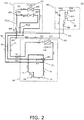
- FIG. 2 a circuit structure of an air conditioning system 1 A of embodiment 2 of the present invention will be described with reference to FIG. 2 .
- parts identical to those in embodiment 1 are identified by identical reference signs.
- the air conditioning system 1 A of embodiment 2 is structurally substantially identical to the air conditioning system 1 of embodiment 1, so mainly the differences with embodiment 1 will be described next.
- an outdoor unit 100' includes a four-port switching valve VF1 (which corresponds to a first switching device of the present invention) that can switch between a first switching state and a second switching state.
- VF1 which corresponds to a first switching device of the present invention
- the first switching state of the four-port switching valve VF1 the first coupling pipe P1 and the discharge pipe Po communicate with each other and the second coupling pipe P2 and the suction pipe Pi communicate with each other
- the second switching state of the four-port switching valve VF1 the first coupling pipe P1 and the suction pipe Pi communicate with each other and the second coupling pipe P2 and the discharge pipe Po communicate with each other.
- the four-port switching valve VF1 has a first port a, a second port b, a third port c, and a fourth port d.
- the first port a is coupled to the other end of the discharge pipe Po
- the second port b is coupled to the one end of the second coupling pipe P2
- the third port c is coupled to the other end of the suction pipe Pi
- the fourth port d is coupled to the one end of the first coupling pipe P1; in the first switching state of the four-port switching valve VF1 the first port a and the fourth port d communicate with each other and the second port b and the third port c communicate with each other
- in the second switching state of the four-port switching valve VF1 the first port a and the second port b communicate with each other and the third port c and the fourth port d communicate with each other.
- the air conditioning system 1A of the present embodiment can switch operation between a hot water supply/dehumidification/heating mode, a dehumidification/heating-only mode, a heating/hot water supply mode, and a hot water supply-only mode.
- a hot water supply/dehumidification/heating mode and the dehumidification/heating-only mode the four-port switching valve VF1 is switched to the first switching state, and in the heating/hot water supply mode and the hot water supply-only mode the four-port switching valve VF1 is switched to the second switching state.
- the hot water supply/dehumidification/heating mode and the dehumidification/heating-only mode of the air conditioning system 1A of the present embodiment are respectively identical to the hot water supply/dehumidification/heating mode and the dehumidification/heating-only mode of the air conditioning system 1 of embodiment 1, so just the heating/hot water supply mode, the hot water supply-only mode, and the heating-only mode will be described next.
- the four-port switching valve VF1 of the outdoor unit 100' is switched to the second switching state (i.e., the state indicated by the solid lines in FIG. 2 ) and the valve V11, the valve V21, the valve V22, the valve V31, and the valve V32 are opened by the control unit of the air conditioning system 1.
- the refrigerant-water heat exchange unit 300 preferably it is ensured that the water in the water pipe P302 of the water circuit SH flows in the direction of the arrow in FIG. 1 .
- the refrigerant is compressed by the compressor 110 of the outdoor unit 100', and the refrigerant compressed in the compressor 110 and discharged to the discharge pipe Po branches at the place of point K11, with some of the refrigerant flowing into the third coupling pipe P3 and with the rest of the refrigerant flowing via the four-port switching valve VF1 into the second coupling pipe P2.
- the refrigerant that has flowed into the third coupling pipe P3 flows via the cutoff valve VC3 out from the outdoor unit 100' and further branches at the place of point K23, with some of the refrigerant flowing into the second indoor-side pipe P202 and being carried to the heating heat exchanger 220 of the indoor dehumidification and heating unit 200 and with the rest of the refrigerant flowing into the refrigerant pipe P301.
- the refrigerant that has flowed into the second coupling pipe P2 flows via the cutoff valve VC2 out from the outdoor unit 100', flows into the first indoor-side pipe P201 at the place of point K21, and is carried to the dehumidification heat exchanger 210 of the indoor dehumidification and heating unit 200.
- the refrigerant that has been carried to the dehumidification heat exchanger 210 exchanges heat in the dehumidification heat exchanger 210 with the room air delivered from the indoor blower device 230 to thereby heat the room air and then flows through the valve V21.
- the refrigerant that has been carried to the heating heat exchanger 220 of the indoor dehumidification and heating unit 200 exchanges heat in the heating heat exchanger 220 with the room air delivered from the indoor blower device 230 to thereby heat the room air and then flows through the valve V22.
- the refrigerant that has flowed through the valve V22 and the refrigerant that has flowed through the valve V21 merge at the place of point K22 and then flow out from the indoor dehumidification and heating unit 200.
- the refrigerant that has flowed into the refrigerant pipe P301 flows through the valve V32, flows into the refrigerant-water heat exchanger 310, and exchanges heat in the refrigerant-water heat exchanger 310 with the water flowing in the water pipe P302 to thereby heat the water flowing in the water pipe P302 and provide hot water.
- the refrigerant that has exchanged heat in the refrigerant-water heat exchanger 310 with the water flowing in the water pipe P302 flows through the valve V31, then flows into the first coupling pipe P1 at the place of point K30, and merges at the place of point K20 with the refrigerant flowing out from the indoor dehumidification and heating unit 200, and the merged flows of refrigerant together flow via the cutoff valve VC1 into the outdoor unit 100'.
- the four-port switching valve VF1 of the outdoor unit 100' is switched to the second switching state (i.e., the state indicated by the solid lines in FIG. 2 ), the valve V11, the valve V31, and the valve V32 are opened, and the valve V21 and the valve V22 are partially opened by the control unit of the air conditioning system 1.
- the refrigerant-water heat exchange unit 300 preferably it is ensured that the water in the water pipe P302 of the water circuit SH flows in the direction of the arrow in FIG. 1 .
- the way the refrigerant flows is substantially identical to the way the refrigerant flows in the heating/hot water supply mode, so it will not be described in detail again here.
- the four-port switching valve VF1 of the outdoor unit 100' is switched to the second switching state (i.e., the state indicated by the solid lines in FIG. 2 ), the valve V11, the valve V21, and the valve V22 are opened, and the valve V31 is closed by the control unit of the air conditioning system 1, but here the valve V32 may be opened or may be closed.
- the valve V32 may be opened or may be closed.
- the way the refrigerant flows is substantially identical to the way the refrigerant flows in the heating/hot water supply mode, so it will not be described in detail again here.
- the air conditioning system 1A can operate in the hot water supply/dehumidification/heating mode, the dehumidification/heating-only mode, the heating/hot water supply mode, the hot water supply-only mode, and the heating-only mode.
- the four-port switching valve VF1 of the outdoor unit 100' can be switched to the second switching state to thereby cause both the dehumidification heat exchanger 210 and the heating heat exchanger 220 to fulfill roles as condensers to heat the room air. For this reason, overall efficiency can be enhanced.
- FIG. 3 a circuit structure of an air conditioning system 1B of embodiment 3 of the present invention will be described in detail with reference to FIG. 3 .
- parts identical to those in embodiment 2 are identified by identical reference signs.
- the air conditioning system 1B of embodiment 3 is structurally substantially identical to the air conditioning system 1 A of embodiment 2, so mainly the differences with embodiment 2 will be described next.
- an outdoor unit 100" is provided with a first outdoor-side branching pipe P101 having one end (the end portion positioned in the place of point K13 in FIG. 3 ) coupled to the suction pipe Pi.
- the third coupling pipe P3 has a first section P3-1 (the section from point K11 in FIG. 3 to a port a1 of a four-port switching valve VF2 described below) and a second section P3-2 (the section from a port b1 of the four-port switching valve VF2 described below to point K31 in FIG. 3 ), with the first section P3-1 being coupled to the discharge pipe Po and with the second section P3-2 being coupled to the second indoor-side pipe P202.
- the outdoor unit 100" further includes a four-port switching valve VF2 (which corresponds to a second switching device of the present invention) that can switch between a first switching state and a second switching state.
- a four-port switching valve VF2 (which corresponds to a second switching device of the present invention) that can switch between a first switching state and a second switching state.
- the first switching state of the four-port switching valve VF2 the second section P3-2 of the third coupling pipe P3 and the first section P3-1 of the third coupling pipe P3 communicate with each other
- the second switching state of the four-port switching valve VF2 the second section P3-2 of the third coupling pipe P3 and another end of the first outdoor-side branching pipe P101 communicate with each other.
- the four-port switching valve VF2 has a first port a1, a second port b1, and a third port c1.
- the first port a1 is coupled to the first section P3-1 of the third coupling pipe P3, the second port b1 is coupled to the second section P3-2 of the third coupling pipe P3, and the third port c1 is coupled to the other end of the first outdoor-side branching pipe P101; in the first switching state of the four-port switching valve VF2 the first port a1 and the second port b1 communicate with each other, and in the second switching state of the four-port switching valve VF2 the second port b1 and the third port c1 communicate with each other.
- the outdoor unit 100" is further provided with a second outdoor-side branching pipe P102 having one end (the end portion positioned in the place of point K14 in FIG. 3 ) coupled to the first outdoor-side branching pipe P101, and a throttling device T1 is provided in the middle of the second outdoor-side branching pipe P102.
- the four-port switching valve VF2 further has a fourth port d1 coupled to another end of the second outdoor-side branching pipe P102; in the first switching state of the four-port switching valve VF2 the first port a1 and the second port b1 communicate with each other and the third port c1 and the fourth port d1 communicate with each other, and in the second switching state of the four-port switching valve VF2 the second port b1 and the third port c1 communicate with each other and the first port a1 and the fourth port d1 communicate with each other.
- a capillary tube is suitable for the throttling device T1, whereby the throttling device T1 guides machine oil accumulating in the four-port switching valve VF2 to the circuit, separates and recovers the machine oil, and prevents the machine oil from accumulating in and damaging the four-port switching valve VF2.
- the air conditioning system 1 B of the present embodiment can switch operation between a hot water supply/dehumidification/heating mode, a dehumidification/heating-only mode, a heating/hot water supply mode, a hot water supply-only mode, a heating-only mode, a cooling/cold water supply mode, a cooling-only mode, and a cold water supply-only mode.
- the four-port switching valve VF1 In the hot water supply/dehumidification/heating mode and the dehumidification/heating-only mode the four-port switching valve VF1 is switched to the first switching state and the four-port switching valve VF2 is switched to the first switching state, in the heating/hot water supply mode, the hot water supply-only mode, and the heating-only mode the four-port switching valve VF1 is switched to the second switching state and the four-port switching valve VF2 is switched to the first switching state, and in the cooling/cold water supply mode, the cooling-only mode, and the cold water supply-only mode the four-port switching valve VF1 is switched to the first switching state and the four-port switching valve VF2 is switched to the second switching state.
- the hot water supply/dehumidification/heating mode, the dehumidification/heating-only mode, the heating/hot water supply mode, the hot water supply-only mode, and the heating-only mode of the air conditioning system 1B of the present embodiment are respectively identical to the hot water supply/dehumidification/heating mode, the dehumidification/heating-only mode, the heating/hot water supply mode, the hot water supply-only mode, and the heating-only mode of the air conditioning system 1A of embodiment 2, so just the cooling/cold water supply mode, the cooling-only mode, and the cold water supply-only mode will be described next. (Cooling/Cold Water Supply Mode)
- the four-port switching valve VF1 In the cooling/cold water supply mode the four-port switching valve VF1 is switched to the first switching state (i.e., the state indicated by the solid lines in FIG. 3 ), the four-port switching valve VF2 is switched to the second switching state (i.e., the state indicated by the solid lines in FIG. 3 ), and the valve V11, the valve V21, the valve V22, the valve V31, and the valve V32 are opened by the control unit of the air conditioning system 1B.
- the valve V11, the valve V21, the valve V22, the valve V31, and the valve V32 are opened by the control unit of the air conditioning system 1B.
- the refrigerant-water heat exchange unit 300 preferably it is ensured that the water in the water pipe P302 of the water circuit SH flows in the direction of the arrow in FIG. 3 .
- the refrigerant is compressed by the compressor 110 of the outdoor unit 100", and the refrigerant compressed in the compressor 110 and discharged to the discharge pipe Po flows into the first coupling pipe P1 and is carried to the outdoor heat exchanger 120.
- the refrigerant that has been carried to the outdoor heat exchanger 120 exchanges heat in the outdoor heat exchanger 120 with the outdoor air delivered from the outdoor blower device 140 and then flows through the valve V11.
- the refrigerant that has flowed through the valve V11 flows via the cutoff valve VC1 out from the outdoor unit 100" and branches at the place of point K20, with some of the refrigerant flowing into the refrigerant pipe P301 of the refrigerant-water heat exchange unit 300 at the place of point K30 and with the rest of the refrigerant flowing into the first indoor-side pipe P201 of the indoor dehumidification and heating unit 200.
- the refrigerant that has flowed into the refrigerant pipe P301 flows through the valve V31 and is carried to the refrigerant-water heat exchanger 310.
- the refrigerant that has been carried to the refrigerant-water heat exchanger 310 exchanges heat in the refrigerant-water heat exchanger 310 with the water flowing in the water pipe P302 of the water circuit SH to thereby cool the water in the water pipe P302 and utilize the water circuit SH to provide cold water. Thereafter, the refrigerant flows into the third coupling pipe P3 at the place of point K31.
- the refrigerant that has flowed into the first indoor-side pipe P201 of the indoor dehumidification and heating unit 200 further branches at the place of point K22 in FIG. 3 , with some of the refrigerant flowing through the valve V21 and being carried to the dehumidification heat exchanger 210 and with the rest of the refrigerant flowing through the valve V22 and being carried to the heating heat exchanger 220.
- the refrigerant that has been carried to the dehumidification heat exchanger 210 exchanges heat in the dehumidification heat exchanger 210 with the room air delivered from the indoor blower device 230 to thereby cool the room air.
- the refrigerant that has exchanged heat in the dehumidification heat exchanger 210 with the room air flows into the second coupling pipe P2 at the place of point K21, then flows via the cutoff valve VC2 into the outdoor unit 100", and then flows via the four-port switching valve VF1 into the suction pipe Pi.
- the refrigerant that has been carried to the heating heat exchanger 220 exchanges heat in the heating heat exchanger 220 with the room air delivered from the indoor blower device 230 to thereby cool the room air.
- the refrigerant that has exchanged heat in the heating heat exchanger 220 with the room air merges at the place of point K23 with the refrigerant that has flowed thereto from the place of point K31, and the merged refrigerant flows via the third cutoff valve VC3 into the outdoor unit 100".
- the refrigerant flows via the four-port switching valve VF2 into the first outdoor-side branching pipe P101 and merges at the place of point K13 in FIG. 3 with the refrigerant that has flowed from the second coupling pipe P2 into the suction pipe Pi, and the merged refrigerant then returns via the reserve tank 130 to the compressor 110.
- the four-port switching valve VF1 is switched to the first switching state (i.e., the state indicated by the solid lines in FIG. 3 )
- the four-port switching valve VF2 is switched to the second switching state (i.e., the state indicated by the solid lines in FIG. 3 )
- the valve V11, the valve V21, and the valve V22 are opened
- the valve V31 is closed by the control unit of the air conditioning system 1B, but here the valve V32 may be opened or closed.
- the valve V32 may be opened or closed.
- the way the refrigerant flows is substantially identical to the way the refrigerant flows in the cooling/cold water supply mode, so it will not be described in detail again here.
- the four-port switching valve VF1 is switched to the first switching state (i.e., the state indicated by the solid lines in FIG. 3 )
- the four-port switching valve VF2 is switched to the second switching state (i.e., the state indicated by the solid lines in FIG. 3 )
- the valve V11, the valve V31, and the valve V32 are opened
- the valve V21 and the valve V22 are partially opened by the control unit of the air conditioning system 1B.
- the refrigerant-water heat exchange unit 300 preferably it is ensured that the water in the water pipe P302 of the water circuit SH flows in the direction of the arrow in FIG. 3 .
- the way the refrigerant flows is substantially identical to the way the refrigerant flows in the cooling/cold water supply mode, so it will not be described in detail again here.
- the states (including the coupling state of each port of the four-port switching valves) of the four-port switching valve VF1, the four-port switching valve VF2, the valve P11, the valve V21, the valve V22, the valve V31, and the valve V32 in each mode of the air conditioning system 1 B of the present embodiment are shown in Table 1 below.
- the hot water supply/dehumidification/heating mode and the dehumidification/heating-only mode correspond to a second mode of the present invention
- the heating/hot water supply mode, the hot water supply-only mode, and the heating-only mode correspond to a first mode of the present invention
- the cooling/cold water supply mode, the cooling-only mode, and the cold water supply-only mode correspond to a third mode of the present invention.
- the air conditioning system 1B can operate in the hot water supply/dehumidification/heating mode, the dehumidification/heating-only mode, the heating/hot water supply mode, the hot water supply-only mode, the heating-only mode, the cooling/cold water supply mode, the cooling-only mode, and the cold water supply-only mode.
- the four-port switching valve VF1 can be switched to the first switching state and the four-port switching valve VF2 can be switched to the second switching state to thereby cause both the dehumidification heat exchanger 210 and the heating heat exchanger 220 to fulfill roles as evaporators to cool the room air. For this reason, overall efficiency can be enhanced.
- the air conditioning system 1B of the present embodiment can perform a routine defrost operation in the cooling-only mode.
- the operation of the indoor blower device 230 is stopped so that the drop in the room temperature does not affect the comfort experienced by persons in the room, but the indoor blower device 230 is not limited to this and can also be operated at a low speed to provide a weak airflow to the room.
- the defrost speed of the routine defrost operation performed in the cooling-only mode is faster.
- FIG. 4 parts identical to those in embodiment 3 are identified by identical reference signs.
- the air conditioning system 1C of embodiment 4 is structurally substantially identical to the air conditioning system 1B of embodiment 3, so mainly the differences with embodiment 3 will be described next.
- the air conditioning system 1C is based on the air conditioning system 1B of embodiment 3 and further includes an indoor unit 400A and an indoor unit 400B that include an indoor unit-side refrigerant pipe P401A and an indoor unit-side refrigerant pipe P401B, one ends (the end portions positioned in the places of point K40A and point K40B in FIG. 4 ) of the indoor unit-side refrigerant pipe P401A and the indoor unit-side refrigerant pipe P401B are coupled to the section of the first coupling pipe P1 positioned outside the outdoor unit 100, other ends (the end portions positioned in the places of point K41A and point K41B in FIG.
- a valve V41A and a valve V41 B (which correspond to an indoor unit-side refrigerant regulating device of the present invention) and an indoor unit-side heat exchanger 410A and an indoor unit-side heat exchanger 410B are provided in the middle of the indoor unit-side refrigerant pipe P401A and the indoor unit-side refrigerant pipe P401B sequentially from the one ends of the indoor unit-side refrigerant pipe P401A and the indoor unit-side refrigerant pipe P401B.
- the indoor unit 400A and the indoor unit 400B can perform the cooling operation
- the indoor unit 400A and the indoor unit 400B can perform the heating operation.
- FIG. 5 parts identical to those in embodiment 4 are identified by identical reference signs.
- the air conditioning system 1D of embodiment 5 is structurally substantially identical to the air conditioning system 1C of embodiment 4, so mainly the differences with embodiment 4 will be described next.
- the air conditioning system 1D includes an outdoor unit 100A corresponding to the outdoor unit 100" of embodiment 4 and further includes an outdoor unit 100B whose structure is identical to that of the outdoor unit 100A, and the outdoor unit 100A and the outdoor unit 100B are coupled in parallel to each other utilizing the first coupling pipe P1, the second coupling pipe P2, and the third coupling pipe P3.
- an outdoor unit coupling pipe span P1A and an outdoor unit coupling pipe span P1B of the first coupling pipe P1 that are coupled to the outdoor unit 100A and the outdoor unit 100B merge with a total coupling pipe span P1T of the first coupling pipe P1 outside the outdoor unit 100A and the outdoor unit 100B; the one end (the end portion positioned in the place of point K20 in FIG. 5 ) of the first indoor-side pipe P201, the one end (the end portion positioned in the place of point K30 in FIG. 5 ) of the refrigerant pipe P310 of the refrigerant-water heat exchange unit 300, and the one ends (the end portions positioned in the places of point K40A and point K40B in FIG.
- the indoor unit-side refrigerant pipe P401A and the indoor unit-side refrigerant pipe P401B are coupled to the total coupling pipe span P1T of the first coupling pipe P1; an outdoor unit coupling pipe span P2A and an outdoor unit coupling pipe span P2B of the second coupling pipe P2 that are coupled to the outdoor unit 100A and the outdoor unit 100B merge with a total coupling pipe span P2T of the second coupling pipe P2 outside the outdoor unit 100A and the outdoor unit 100B; the other end (the end portion positioned in the place of point K21 in FIG. 5 ) of the first indoor-side pipe P201 and the other ends (the end portions positioned in the places of point K41A and point K41B in FIG.
- the indoor unit-side refrigerant pipe P401A and the indoor unit-side refrigerant pipe P401B are coupled to the total coupling pipe span P2T of the second coupling pipe P2; an outdoor unit coupling pipe span P3A and an outdoor unit coupling pipe span P3B of the third coupling pipe P3 that are coupled to the outdoor unit 100A and the outdoor unit 100B merge with a total coupling pipe span P3T of the third coupling pipe P3 outside the outdoor unit 100A and the outdoor unit 100B; and the other end (the end portion positioned in the place of point K23 in FIG. 5 ) of the second indoor-side pipe P202 and the other end (the end portion positioned in the place of point K31 in FIG. 5 ) of the refrigerant pipe P310 are coupled to the total coupling pipe span P3T of the third coupling pipe P3.
- refrigerant of a suitable temperature, a suitable quantity, and a suitable pressure can be supplied to, for example, the indoor dehumidification and heating unit 200 and the refrigerant-water heat exchange unit 300 by simultaneously starting up the outdoor unit 100A and the outdoor unit 100B.
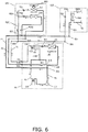
- a sub-cooling circuit including a sub-cooling pipe P106, a valve V12 (which corresponds to a refrigerant regulating device of the present invention), and a sub-cooler 150 can also be provided in the outdoor unit 100.
- One end (the end portion positioned in the place of point K16 in FIG. 6 ) of the sub-cooling pipe P106 is coupled to the first coupling pipe P1 in a position located on the side of the outdoor heat exchanger 120 corresponding to another end of the first coupling pipe P1, another end (the end portion positioned in the place of point K15 in FIG.
- the valve V12 is provided in the middle of the sub-cooling pipe P106, and the sub-cooler 150 exchanges heat between the refrigerant flowing in the first coupling pipe P1 and the refrigerant that has flowed through the valve V12 in the sub-cooling pipe P106.
- the sub-cooler 150 can be utilized to cool the refrigerant flowing in the first outdoor-side branching pipe P101, whereby the capacity to dehumidify the room air delivered from the indoor blower device 230 utilizing the dehumidification heat exchanger 210 of the indoor dehumidification and heating unit 200 can be enhanced.
- a sub-cooling circuit such as shown in FIG. 6 can also be provided in embodiment 2 to embodiment 5.
- a valve V13 (which corresponds to a refrigerant control valve of the present invention) can also be provided in the middle of the second coupling pipe P2 (the section between the one end of the second coupling pipe P2 and the cutoff valve VC2 in FIG. 7 , but it is not limited to this).
- any one type among a motor-operated valve, an electromagnetic valve, or a pilot valve can be used as the valve V 13.
- the refrigerant accumulating in the indoor dehumidification and heating unit 200 can be effectively reduced, whereby the refrigerant flowing in the refrigerant-water heat exchange unit 300 can be increased, so that the heating capacity of the refrigerant with respect to the water in the refrigerant-water heat exchange unit 300 can be enhanced.
- valve V 13 shown in FIG. 7 can also be provided in embodiment 3 to embodiment 5.
- the one end of the first outdoor-side branching pipe P201 is coupled to the suction pipe Pi, but it is not limited to this; as shown in FIG. 8 , the one end of the first outdoor-side branching pipe P101 can also be coupled to the reserve tank 130.
- the coupling configuration of the first outdoor-side branching pipe P101 such as shown in FIG. 8 can also be used in embodiment 4 and embodiment 5.
- a floor heating water circuit 500, a water tank SX, and a fan coil unit 700 can also be connected to the water circuit SH of the refrigerant-water heat exchange unit 300.
- the water pipe P302 includes a main pipeline P3021 and a branching pipeline P3022 that is connected via a three-port valve VC4 to the main pipeline P3021.
- the floor heating water circuit 500 includes a floor heating water pipe P501 both ends of which are connected to the main pipeline P3021 of the water pipe P302.
- the branching pipeline P3022 runs through the water tank SX, which is provided with a water suction pipe P601 and a domestic water pipe P602 that is connected to a terminal end 610 of domestic water such as a faucet or a shower head.
- the fan coil unit 700 includes a coil circuit water pipe P701 both ends of which are connected to the main pipeline P3021 of the water pipe P302.
- the floor heating water circuit 500 includes only one floor heating water pipe P501, but the floor heating water circuit 500 is not limited to this and may also include plural floor heating water pipes P501 connected in parallel.
- the fan coil unit 700 includes only one coil circuit water pipe P701, but the fan coil unit 700 is not limited to this and may also include plural coil circuit water pipes P701 connected in parallel.
- the fan coil unit 700 may also be connected to the water circuit SH of the refrigerant-water heat exchange unit 300.
- the dehumidification heat exchanger 210 is provided on the upstream side of the heating heat exchanger 220 in the flow path of the air formed by the indoor blower device 230, so that the air is first heated and is then dehumidified, but the dehumidification heat exchanger is not limited to this and may also be provided on the downstream side of the heating heat exchanger in the flow path of the air formed by the indoor blower device, so that the air is first heated and is then dehumidified.
- the dehumidification heat exchanger and the heating heat exchanger can also be provided side by side in the flow path of the air formed by the indoor blower device, so that some of the air is dehumidified and some of the air is heated.
- the dehumidification heat exchanger and the heating heat exchanger are not limited to being disposed in the flow path of the air formed by the indoor blower device, and, for example, a water circulation device can also be utilized to perform heat exchange; specifically, a water circulation pipe that exchanges heat with either one of or both the dehumidification heat exchanger and the heating heat exchanger may be provided around either one of or both the dehumidification heat exchanger and the heating heat exchanger to thereby deliver a heat quantity or a cold quantity to the room via circulating water that circulates and flows in the pipe.
- the outdoor unit 100 includes the valve V11, but the outdoor unit 100 is not limited to this and the valve V11 may also be omitted.
- the refrigerant-water heat exchange unit 300 includes the valve V32, but the refrigerant-water heat exchange unit 300 is not limited to this and the valve V32 may also be omitted.
- a motor-operated valve or an electromagnetic valve may also be used as the throttling device T1.
- the four-port switching valve VF2 serving as the second switching device is provided in the outdoor unit of the air conditioning system, this is useful for making compact and miniaturizing the structure of the air conditioning system, but the four-port switching valve VF2 is not limited to this and may also be provided in the indoor dehumidification and heating unit or may also be provided between the outdoor unit and the indoor dehumidification and heating unit.
- the four-port switching valve VF2 is used as the second switching device, but the second switching device is not limited to this and a three-port valve may also be utilized instead of the four-port switching valve VF2.
- the second outdoor-side branching pipe P102 and the throttling device T1 in embodiment 3 to embodiment 5 are removed, and it suffices to couple the three-port valve in such a way that it can switch between a state in which the second section P3-2 of the third coupling pipe P3 and the first section P3-1 of the third coupling pipe P3 communicate with each other and a state in which the second section P3-2 of the third coupling pipe P3 and the other end of the first outdoor-side branching pipe P101 communicate with each other.
- two indoor units comprising the indoor unit 400A and the indoor unit 400B are coupled in parallel to each other by the first coupling pipe P1 and the second coupling pipe P2, but embodiment 4 and embodiment 5 are not limited to this; just one indoor unit may also be connected by the first coupling pipe P1 and the second coupling pipe P2, or three or more indoor units may also be connected in parallel.
- the indoor unit 400A and the indoor unit 400B have identical structures, but the structures of the indoor unit 400A and the indoor unit 400B are not limited to this and may also be different.
- embodiment 5 includes two indoor units comprising the outdoor unit 100A and the outdoor unit 100B, but embodiment 5 is not limited to this and may also include three or more outdoor units.
- the outdoor unit 100A and the outdoor unit 100B have identical structures, but the structures of the outdoor unit 100A and the outdoor unit 100B are not limited to this and may also be different.
- the reserve tank 130 is provided in the middle of the suction pipe Pi, but embodiment 1 to embodiment 5 are not limited to this and the reserve tank 130 may also be omitted.
- a branching pipe part such as a Y-connector, for example, may also be used for branching pipes in the circuit, or pipes may be used as is, have holes bored in them, and be welded together.
- FIG. 1 to FIG. 9 can also be combined with each other provided they are not incompatible with each other, and some constituent parts thereof can also be removed therefrom.
- Patent Document 1 CN1590890A
Landscapes
- Engineering & Computer Science (AREA)
- Physics & Mathematics (AREA)
- Mechanical Engineering (AREA)
- Thermal Sciences (AREA)
- General Engineering & Computer Science (AREA)
- Air Conditioning Control Device (AREA)
- Compression-Type Refrigeration Machines With Reversible Cycles (AREA)
- Other Air-Conditioning Systems (AREA)
Abstract
Description
- The present invention relates to an air conditioning system and a control method of the same, and particularly an air conditioning system including an outdoor unit and an indoor dehumidification and heating unit and a control method of the same.
- As people's living standards improve, people's needs with respect to controlling their living environment become more pronounced by the day, so air conditioning system functions are also gradually expanding from being just for regulating temperature to being diverse. Air conditioning systems equipped with a humidity control function have been created because in rainy and humid regions and in rainy seasons the humidity in the air becomes higher and is also uncomfortably felt by the human body.
- Air conditioning systems generally dehumidify air using the following principle. Moisture in the air is removed by causing the air to flow through a heat exchanger whose surface temperature is lower than the dewpoint of the air to thereby condense the air, and because of this dehumidification principle it is understood that the dehumidifying effect is better the lower the surface temperature of the heat exchanger is. However, although the humidity can be lowered when dehumidification is performed at a low temperature, the temperature of the air also concomitantly drops, so in an environment requiring both a dehumidifying effect and temperature, such as a bathroom, for example, it becomes necessary to maintain the comfort experienced by the human body by heating the air again after dehumidifying the air.
- In order to realize heating and dehumidification, ordinarily a structure has been used where, as shown in
FIG. 10 , anelectric heating unit 29X is added downstream of an airflow path of adehumidification heat exchanger 21 X. However, an electric heating unit ordinarily utilizes a heating element (e.g., a heating wire) to convert electrical energy to thermal energy and raises the blowing air temperature by causing the air to absorb a heat quantity when the air flows through it, so this ends up increasing energy consumption. In addition to this, the airflow that has exchanged heat in the electrical heating unit is unevenly heated, so the temperature distribution of the airflow also becomes uneven and comfort ends up dropping. - In order to realize heating and dehumidification, it is also conceivable to use the structure disclosed in patent document
CN1590890A , where, as shown inFIG. 11 , a dehumidification heat exchanger 21X1 and aheating heat exchanger 22X are connected in series to an indoor refrigerant circuit, the dehumidification heat exchanger 21X1 and theheating heat exchanger 22X are sequentially provided in an airflow path, and athrottling device 25X is provided in a pipe between them. However, when this structure is utilized to perform heating and dehumidification, the heat quantity of the refrigerant in the same section is first used for heating and is then used for cooling after being carried away by the airflow, so both the dehumidification heat exchanger 21X1 and theheating heat exchanger 22X do not exhibit sufficient roles, dehumidification is no longer sufficient, and the heating quantity also becomes deficient. - In addition to this, it is also desired that air conditioning systems have a hot water supply function.
- The present invention has been completed in view of the problems described above, and it is an object thereof to provide an air conditioning system including an outdoor unit and an indoor dehumidification and heating unit and a control method of the same. The air conditioning system can provide a sufficiently dehumidified and heated fluid in an energy conserving way to a room and furthermore has a hot water supply function.
- In order to realize this object, the present invention provides an air conditioning system including an outdoor unit and an indoor dehumidification and heating unit that are coupled to each other via coupling pipes. In the outdoor unit a discharge side of a compressor is coupled to one end of a discharge pipe, another end of the discharge pipe is coupled to one end of a first coupling pipe of the coupling pipes, a suction side of the compressor is coupled to one end of a suction pipe, another end of the suction pipe is coupled to one end of a second coupling pipe of the coupling pipes, and an outdoor-side heat exchanger is provided in a section of the first coupling pipe positioned inside the outdoor unit. In the indoor dehumidification and heating unit a first indoor-side refrigerant regulating device and a first heat exchanger are provided in a first indoor-side pipe sequentially from one end of the first indoor-side pipe, the one end of the first indoor-side pipe is coupled to a section of the first coupling pipe positioned outside the outdoor unit, and another end of the first indoor-side pipe is coupled to a section of the second coupling pipe positioned outside the outdoor unit. In the indoor dehumidification and heating unit a heat cycle device for delivering a heat quantity or a cold quantity of the indoor dehumidification and heating unit to a room is also provided. The coupling pipes further include a third coupling pipe having one end coupled to the discharge pipe. In the indoor dehumidification and heating unit a second indoor-side refrigerant regulating device and a second heat exchanger are provided in a second indoor-side pipe sequentially from one end of the second indoor-side pipe, the one end of the second indoor-side pipe is coupled to the first indoor-side pipe and is positioned between the first indoor-side refrigerant regulating device and the one end of the first indoor-side pipe, and another end of the second indoor-side pipe is coupled to a section of the third coupling pipe positioned outside the outdoor unit. The air conditioning system further includes a refrigerant-water heat exchange unit including a refrigerant pipe, a water circuit configured by a water pipe, and a refrigerant-water heat exchanger that exchanges heat between refrigerant flowing in the refrigerant pipe and water flowing in the water pipe, with one end of the refrigerant pipe being coupled to the section of the first coupling pipe positioned outside the outdoor unit and with another end of the refrigerant pipe being coupled to the section of the third coupling pipe positioned outside the outdoor unit.
- According to the air conditioning system of the present invention, the air conditioning system can operate in a hot water supply/dehumidification/heating mode or a dehumidification/heating-only mode, and in these two modes the first heat exchanger of the indoor dehumidification and heating unit can be utilized to dehumidify the fluid delivered from the heat cycle device and the second heat exchanger of the indoor dehumidification and heating unit can be utilized to heat the fluid delivered from the heat cycle device. Consequently, compared to a structure where an electric heating unit is added downstream of the dehumidification heat exchanger in the flow path formed by the heat cycle device, the air conditioning system of the present invention can reduce energy consumption and can enhance the comfort experienced by persons in the room by ensuring that the temperature distribution of the fluid that the indoor dehumidification and heating unit supplies to the room does not become uneven. Furthermore, compared to a structure where the dehumidification heat exchanger and the heating heat exchanger connected in series in an indoor refrigerant circuit are sequentially provided in the flow path formed by the heat cycle device, the air conditioning system of the present invention can ensure that the dehumidification does not become insufficient and the heating quantity is not deficient because both the dehumidification heat exchanger (i.e., the first heat exchanger) and the heating heat exchanger (i.e., the second heat exchanger) can fulfill sufficient roles. Furthermore, waste heat utilization can be realized by using in the second heat exchanger some of the waste heat that is discharged from the outdoor unit to the atmosphere anyway, so the energy consumption rate can be improved to realize energy conservation and environmental protection.
- Furthermore, according to the air conditioning system of the present invention, even when the system efficiency has dropped because of frosting of the outdoor unit, the air conditioning system can perform a constant-temperature defrost operation in the hot water supply/dehumidification/heating mode or the dehumidification/heating-only mode, which is to say that because the heating heat exchanger fulfills a heating action in the hot water supply/dehumidification/heating mode or the dehumidification/heating-only mode, cold air does not blow to the room even if an indoor blower device continues to be operated, so constant-temperature defrosting can be realized.
- Furthermore, according to the air conditioning system of the present invention, the air conditioning system includes the refrigerant-water heat exchange unit including the refrigerant pipe, the water circuit configured by the water pipe, and the refrigerant-water heat exchanger that exchanges heat between the refrigerant flowing in the refrigerant pipe and the water flowing in the water pipe, so by utilizing the refrigerant carried from the outdoor unit and flowing in the refrigerant pipe to heat the water flowing in the water pipe of the water circuit, the water circuit can be utilized to provide hot water.
- In the air conditioning system of the present invention, preferably the outdoor unit further includes a first switching device that can switch between a first switching state and a second switching state. In the first switching state of the first switching device the first coupling pipe and the discharge pipe communicate with each other and the second coupling pipe and the suction pipe communicate with each other, and in the second switching state of the first switching device the first coupling pipe and the suction pipe communicate with each other and the second coupling pipe and the discharge pipe communicate with each other.
- By using this structure, the air conditioning system can operate in a hot water supply/dehumidification/heating mode, a dehumidification/heating-only mode, a heating/hot water supply mode, and a hot water supply-only mode.
- Furthermore, by using this structure, the first switching state of the outdoor unit can be switched to the second switching state to thereby cause both the first heat exchanger and the second heat exchanger to fulfill roles as condensers to heat the fluid delivered from the heat cycle device. For this reason, overall efficiency can be enhanced.
- In the air conditioning system of the present invention, preferably the outdoor unit is further provided with a first outdoor-side branching pipe having one end coupled to the suction pipe, the third coupling pipe has a first section and a second section, with the first section being coupled to the discharge pipe and with the second section being coupled to the second indoor-side pipe, and the air conditioning system further includes a second switching device that can switch between a first switching state and a second switching state. In the first switching state of the second switching device the second section of the third coupling pipe and the first section of the third coupling pipe communicate with each other, and in the second switching state of the second switching device the second section of the third coupling pipe and another end of the first outdoor-side branching pipe communicate with each other.
- By using this structure, the air conditioning system can operate in a hot water supply/dehumidification/heating mode, a dehumidification/heating-only mode, a heating/hot water supply mode, a hot water supply-only mode, and a cooling-only mode.
- Furthermore, by using this structure, the first switching device can be switched to the first switching state and the second switching device can be switched to the second switching state to thereby cause both the first heat exchanger and the second heat exchanger to fulfill roles as evaporators to cool the room air. For this reason, overall efficiency can be enhanced.
- Furthermore, by using this structure, even when the system efficiency has dropped because of frosting of the outdoor unit, the air conditioning system can perform a routine defrost operation in the cooling-only mode. At this time, preferably the operation of the heat cycle device is stopped to ensure that the drop in the room temperature does not affect the comfort experienced by persons in the room, but the heat cycle device is not limited to this and can also be operated at a low speed to provide a weak airflow to the room. In this connection, compared to the constant-temperature defrost operation, the defrost speed of the routine defrost operation performed in the cooling-only mode is faster.
- In the air conditioning system of the present invention, preferably the first switching device is a four-port valve.
- By using this structure, a simple structure can be utilized to realize the switching of the first switching device between the first switching state and the second switching state.
- In the air conditioning system of the present invention, preferably the first indoor-side refrigerant regulating device and the second indoor-side refrigerant regulating device are motor-operated valves or electromagnetic valves.
- By using this structure, simple structures can be utilized to regulate the state of the refrigerant flowing in the first indoor-side pipe and the second indoor-side pipe.
- In the air conditioning system of the present invention, preferably the heat cycle device is an indoor blower device, and the first heat exchanger and the second heat exchanger are provided in a flow path of an airflow formed by the indoor blower device.
- In the air conditioning system of the present invention, preferably the first heat exchanger is provided on an upstream side or a downstream side of the second heat exchanger in the flow path or the first heat exchanger and the second heat exchanger are provided side by side in the flow path.
- By using this structure, it can be made easier to deliver the necessary heat quantity or cold quantity to the room.
- In the air conditioning system of the present invention, preferably a reservoir device is provided in the suction pipe.
- By using this structure, the reservoir device can be utilized to absorb the liquid component in the refrigerant returned to the compressor, so that the compressor does not suck in liquid refrigerant and sustain damage.
- In the air conditioning system of the present invention, preferably the air conditioning system further includes a floor heating water circuit connected to the water circuit.
- By using this structure, the refrigerant-water heat exchange unit can be utilized to heat floorboards or the like.
- In the air conditioning system of the present invention, preferably the air conditioning system further includes a water tank provided with a domestic water pipe connected to a terminal end of domestic water, and the water pipe configuring the water circuit runs through the water tank.
- By using this structure, the refrigerant-water heat exchange unit can be utilized to heat floorboards or the like and provide hot water to the terminal end of domestic water.
- In the air conditioning system of the present invention, preferably there is an electric heating device in the water tank.
- By using this structure, even when the heat quantity of the water supplied to the water tank of the water flowing in the water pipe in the water circuit is deficient, the electric heating device can be utilized to heat the water in the water tank and thereby provide water with the necessary temperature to the terminal end of domestic water.
- In the air conditioning system of the present invention, preferably the air conditioning system further includes a fan coil unit connected to the water circuit.
- By using this structure, the refrigerant-water heat exchange unit can be utilized to heat or cool the water flowing in the water circuit to thereby provide the heat quantity or cold quantity of the water in the water circuit to the fan coil unit, and the fan coil unit can be utilized to heat or cool.
- In the air conditioning system of the present invention, preferably the outdoor unit further includes a sub-cooling pipe, a refrigerant regulating device, and a sub-cooler, one end of the sub-cooling pipe is coupled to the first coupling pipe in a position located on the side of the outdoor heat exchanger corresponding to another end of the first coupling pipe, and another end of the sub-cooling pipe is coupled to the suction pipe, the refrigerant regulating device is provided in the sub-cooling pipe, and the sub-cooler exchanges heat between refrigerant flowing in the first coupling pipe and refrigerant that has flowed through the refrigerant regulating device in the sub-cooling pipe.
- By using this structure, the sub-cooler can be utilized to cool the refrigerant flowing in the first outdoor-side pipe, whereby the capacity to dehumidify the fluid delivered from the heat cycle device utilizing the first heat exchanger of the indoor dehumidification and heating unit can be enhanced.
- In the air conditioning system of the present invention, preferably the air conditioning system further includes at least one indoor unit, the indoor unit includes an indoor unit-side refrigerant pipe, one end of the indoor unit-side refrigerant pipe is coupled to the section of the first coupling pipe positioned outside the outdoor unit, another end of the indoor unit-side refrigerant pipe is coupled to the section of the second coupling pipe positioned outside the outdoor unit, and an indoor unit-side refrigerant regulating device and an indoor unit-side heat exchanger are provided in the indoor unit-side refrigerant pipe sequentially from the one end of the indoor unit-side refrigerant pipe.
- By using this structure, not only can the indoor dehumidification and heating unit be utilized to perform dehumidification and heating, but the refrigerant-water heat exchange unit can be utilized to provide hot water, and cooling by the indoor unit can also be done.
- In the air conditioning system of the present invention, preferably the air conditioning system includes a plurality of the outdoor units, outdoor unit coupling pipe spans of the first coupling pipe that are coupled to the plural outdoor units merge with a total coupling pipe span of the first coupling pipe outside the outdoor units, the one end of the first indoor-side pipe and the one end of the refrigerant pipe of the refrigerant-water heat exchange unit are coupled to the total coupling pipe span of the first coupling pipe, outdoor unit coupling pipe spans of the second coupling pipe that are coupled to the plural outdoor units merge with a total coupling pipe span of the second coupling pipe outside the outdoor units, the other end of the first indoor-side pipe is coupled to the total coupling pipe span of the second coupling pipe, and outdoor unit coupling pipe spans of the third coupling pipe that are coupled to the plural outdoor units merge with a total coupling pipe span of the third coupling pipe outside the outdoor units, and the other end of the second indoor-side pipe and the other end of the refrigerant pipe are coupled to the total coupling pipe span of the third coupling pipe.
- By using this structure, even when the capacity of one outdoor unit is deficient, refrigerant with the proper temperature, proper quantity, and proper pressure can be provided to the indoor dehumidification and heating unit and the refrigerant-water heat exchange unit by starting up the plural outdoor units.
- In the air conditioning system of the present invention, preferably a refrigerant-water heat exchange unit-side refrigerant regulating device is provided between the one end of the refrigerant pipe and the refrigerant-water heat exchanger.
- By using this structure, the flow rate and state of the refrigerant flowing in the refrigerant pipe can be controlled.
- In the air conditioning system of the present invention, preferably the refrigerant-water heat exchange unit-side refrigerant regulating device is a motor-operated valve or an electromagnetic valve.
- By using this structure, a simple structure can be utilized to control the flow rate and state of the refrigerant flowing in the refrigerant pipe.
- In the air conditioning system of the present invention, preferably an electromagnetic valve is provided between the other end of the refrigerant pipe and the refrigerant-water heat exchanger.
- By using this structure, the electromagnetic valve is provided between the other end of the refrigerant pipe and the refrigerant-water heat exchanger, so even when the temperature of the refrigerant flowing from the third coupling pipe to the refrigerant-water heat exchange unit is too low, the electromagnetic valve can be closed to ensure that freezing does not occur as a result of the temperature of the refrigerant in the refrigerant pipe being too low.
- In the air conditioning system of the present invention, preferably a refrigerant control valve is provided in the second coupling pipe.
- By using this structure, when the first switching device is switched to the second switching state, and the refrigerant-water heat exchange unit-side refrigerant regulating device is opened, and the first indoor-side refrigerant regulating device and the second indoor-side refrigerant regulating device are partially opened to switch to the hot water supply-only mode, the refrigerant accumulating in the indoor dehumidification and heating unit can be effectively reduced, whereby the refrigerant flowing in the refrigerant-water heat exchange unit can be increased, so that the heating capacity of the refrigerant in the refrigerant-water heat exchange unit with respect to the water can be enhanced.
- In this connection, "partially open" mentioned in this specification is not intended to carry a meaning such as "open" or "completely open" nor is it intended to convey the meaning of "completely closed"; rather, it means to open the valve just a little so that the valve itself does not sustain damage (that is to say, to open the valve just a little and balance out the pressure at both ends of the valve to ensure that the liquid pressure at both ends of the valve does not become imbalanced resulting in the valve sustaining damage), and this substantially corresponds to "closed." Furthermore, "open" mentioned in this specification does not at all mean completely opening the valve, and the specific opening degree of the valve can be controlled according to the requirements of the operating circumstances.
- In the air conditioning system of the present invention, preferably the refrigerant control valve is any one type among a motor-operated valve, an electromagnetic valve, or a pilot valve.
- By using this structure, the refrigerant control valve can be inexpensively configured.
- In the air conditioning system of the present invention, preferably the second switching device is provided in the outdoor unit.
- By using this structure, the second switching device is integrated into the outdoor unit, which is useful for making compact and downsizing the structure of the air conditioning system.
- In order to realize the above-described object, the present invention provides an air conditioning system control method that is used to control the above-described air conditioning system, wherein a refrigerant-water heat exchange unit-side refrigerant regulating device is provided between the one end of the refrigerant pipe and the refrigerant-water heat exchanger. The air conditioning system control method utilizes a control unit to cause the air conditioning system to switch operation between a first mode, a second mode, and a third mode, in the first mode the first switching device is switched to the second switching state and the second switching device is switched to the first switching state, in the second mode the first switching device is switched to the first switching state, the second switching device is switched to the first switching state, and the first indoor-side refrigerant regulating device and the second indoor-side refrigerant regulating device are opened, and in the third mode the first switching device is switched to the first switching state and the second switching device is switched to the second switching state.
- In the air conditioning system control method pertaining to the present invention, preferably in the second mode the air conditioning system performs a defrost operation.
- In the air conditioning system control method pertaining to the present invention, preferably in the third mode the first indoor-side refrigerant regulating device and the second indoor-side refrigerant regulating device are opened and operation of the heat cycle device is stopped or the heat cycle device is operated at a low speed to thereby perform a defrost operation.
- In the air conditioning system control method pertaining to the present invention, preferably in the first mode or the third mode the first indoor-side refrigerant regulating device, the second indoor-side refrigerant regulating device, and the refrigerant-water heat exchange unit-side refrigerant regulating device are opened.
- In the air conditioning system control method pertaining to the present invention, preferably in the first mode or the third mode the first indoor-side refrigerant regulating device and the second indoor-side refrigerant regulating device are partially opened and the refrigerant-water heat exchange unit-side refrigerant regulating device is opened.
- In the air conditioning system control method pertaining to the present invention, preferably in the first mode or the third mode the first indoor-side refrigerant regulating device and the second indoor-side refrigerant regulating device are opened and the refrigerant-water heat exchange unit-side refrigerant regulating device is closed.
- In the air conditioning system control method pertaining to the present invention, preferably a refrigerant control valve is provided in the second coupling pipe, and in the first mode the refrigerant control valve is closed, the first indoor-side refrigerant regulating device and the second indoor-side refrigerant regulating device are partially opened, and the refrigerant-water heat exchange unit-side refrigerant regulating device is opened.
- In the air conditioning system control method pertaining to the present invention, preferably the refrigerant control valve is any one type among a motor-operated valve, an electromagnetic valve, or a pilot valve.
- According to the air conditioning system and the control method of the same of the present invention, the air conditioning system can operate in a hot water supply/dehumidification/heating mode or a dehumidification/heating-only mode, and in these two modes the first heat exchanger of the indoor dehumidification and heating unit can be utilized to dehumidify the fluid delivered from the heat cycle device and the second heat exchanger of the indoor dehumidification and heating unit can be utilized to heat the fluid delivered from the heat cycle device. Consequently, compared to a structure where an electric heating unit is added downstream of the first heat exchanger in the flow path formed by the heat cycle device, the air conditioning system of the present invention can reduce energy consumption and can enhance the comfort experienced by persons in the room by ensuring that the temperature distribution of the fluid that the indoor dehumidification and heating unit supplies to the room does not become uneven. Furthermore, compared to a structure where the first heat exchanger and the second heat exchanger connected in series in the indoor refrigerant circuit are sequentially provided in the flow path formed by the heat cycle device, the air conditioning system of the present invention can ensure that the dehumidification does not become insufficient and the heating quantity is not deficient because both the first heat exchanger and the second heat exchanger can fulfill sufficient roles. Furthermore, waste heat utilization can be realized by using in the second heat exchanger some of the waste heat that is discharged from the outdoor unit to the atmosphere anyway, so the energy consumption rate can be improved to realize energy conservation and environmental protection.
- Furthermore, according to the air conditioning system and the control method of the same of the present invention, even when a system efficiency decreases by frosting of the outdoor unit, the air conditioning system can perform a constant-temperature defrost operation in the hot water supply/dehumidification/heating mode or the dehumidification/heating-only mode, which is to say that because the heating heat exchanger effects a heating action in the hot water supply/dehumidification/heating mode or the dehumidification/heating-only mode, cold air does not blow to the room even when an indoor blower device continues to be operated, so constant-temperature defrosting can be realized.
- Furthermore, according to the air conditioning system and the control method of the same of the present invention, by utilizing the refrigerant carried from the outdoor unit and flowing in the refrigerant pipe to heat the water flowing in the water pipe of the water circuit, the water circuit can be utilized to provide hot water.
-
-
FIG. 1 is a schematic drawing showing a circuit structure of an air conditioning system ofembodiment 1 of the present invention, and shows the direction in which refrigerant flows when the air conditioning system is operated in a hot water supply/dehumidification/heating mode. -
FIG. 2 is a schematic drawing showing a circuit structure of an air conditioning system of embodiment 2 of the present invention, and shows the direction in which refrigerant flows when the air conditioning system is operated in a heating/hot water supply mode. -
FIG. 3 is a schematic drawing showing a circuit structure of an air conditioning system of embodiment 3 of the present invention, and shows the direction in which refrigerant flows when the air conditioning system is operated in a cooling/cold water supply mode. -
FIG. 4 is a schematic drawing showing a circuit structure of an air conditioning system of embodiment 4 of the present invention. -
FIG. 5 is a schematic drawing showing a circuit structure of an air conditioning system of embodiment 5 of the present invention. -
FIG. 6 is a schematic drawing showing a modification of the air conditioning system pertaining to the present invention, and shows the direction in which refrigerant flows when the air conditioning system is operated in the hot water supply/dehumidification/heating mode. -
FIG. 7 is a schematic drawing showing another modification of the air conditioning system pertaining to the present invention, and shows the direction in which refrigerant flows when the air conditioning system is operated in a hot water supply-only mode. -
FIG. 8 is a schematic drawing showing still another example modification of the air conditioning system pertaining to the present invention. -
FIG. 9 is a schematic drawing showing part of a refrigerant-water heat exchange unit included in the air conditioning system pertaining to the present invention, and shows an example where a floor heating water circuit, a water tank, and a fan coil unit are connected to a water circuit of the refrigerant-water heat exchange unit. -
FIG. 10 is a schematic diagram showing a conventional dehumidification and heating circuit structure. -
FIG. 11 is a schematic diagram showing another conventional dehumidification and heating circuit structure. - Next, embodiments of the air conditioning system pertaining to the present invention will be described with reference to the drawings.
- First, a circuit structure of an
air conditioning system 1 ofembodiment 1 of the present invention will be described in detail with reference toFIG. 1 . - As shown in
FIG. 1 , theair conditioning system 1 of the present embodiment includes anoutdoor unit 100, an indoor dehumidification andheating unit 200, and a refrigerant-waterheat exchange unit 300, and theoutdoor unit 100, the indoor dehumidification andheating unit 200, and the refrigerant-waterheat exchange unit 300 are coupled to each other via plural coupling pipes including a first coupling pipe P1, a second coupling pipe P2, and a third coupling pipe P3. - Here, cutoff valves VC1 to VC3 are provided in the middle of the first coupling pipe P1, the second coupling pipe P2, and the third coupling pipe P3 (below, the cutoff valves VC1 to VC3 also serve as a boundary in defining the range of the outdoor unit), and ordinarily the cutoff valves VC1 to VC3 are all in a normally open state. Furthermore, in certain cases one, plurality, or even all of the cutoff valves VC1 to VC3 may also be omitted.
- The
outdoor unit 100 is provided with acompressor 110, anoutdoor heat exchanger 120, a valve V11, and a reserve tank 130 (which corresponds to a reservoir device of the present invention). - Specifically, a discharge side of the
compressor 110 is coupled to one end of a discharge pipe Po, another end of the discharge pipe Po (the end portion positioned in the place of point K12 inFIG. 1 ) is coupled to one end of the first coupling pipe P1, a suction side of thecompressor 110 is coupled to one end of a suction pipe Pi, another end of the suction pipe Pi (the end portion positioned in the place of point K10 inFIG. 1 ) is coupled to one end of the second coupling pipe P2, the valve V11 and theoutdoor heat exchanger 120 are provided in the middle of a section of the first coupling pipe P1 positioned inside the outdoor unit 100 (the section from point K12 to the cutoff valve VC1 inFIG. 1 ), and thereserve tank 130 is provided in the middle of the suction pipe Pi. Furthermore, one end of the third coupling pipe P3 (the end portion positioned in the place of point K11 inFIG. 1 ) branches from the discharge pipe Po. - Here, the
outdoor unit 100 is also provided with anoutdoor blower device 140 for delivering air to theoutdoor heat exchanger 120. - Furthermore, the valve V 11 may be a motor-operated valve or an electromagnetic valve.
- The indoor dehumidification and
heating unit 200 is provided with a valve 21 (which corresponds to a first indoor-side refrigerant regulating device of the invention), a dehumidification heat exchanger 210 (which corresponds to a first heat exchanger of the invention), a valve V22 (which corresponds to a second indoor-side refrigerant regulating device of the invention), and a heating heat exchanger 220 (which corresponds to a second heat exchanger of the invention). - Specifically, the valve V21 and the
dehumidification heat exchanger 210 are provided in the middle of a first indoor-side pipe P201 sequentially from one end (the end portion positioned in the place of point K20 inFIG. 1 ) of the first indoor-side pipe P201, the one end of the first indoor-side pipe P201 is coupled to a section of the first coupling pipe P1 positioned outside theoutdoor unit 100, and another end (the end portion positioned in the place of point K21 inFIG. 1 ) of the first indoor-side pipe P201 is coupled to a section of the second coupling pipe P2 positioned outside theoutdoor unit 100. Moreover, the valve V22 and theheating heat exchanger 220 are provided in the middle of a second indoor-side pipe P202 sequentially from one end (the end portion positioned in the place of point K22 inFIG. 1 ) of the second indoor-side pipe P202, the one end of the second indoor-side pipe P202 is coupled to the first indoor-side pipe P201 and is positioned between the valve V21 and the one end of the first indoor-side pipe P201, and another end (the end portion positioned in the place of point K23 inFIG. 1 ) of the second indoor-side pipe P202 is coupled to a section of the third coupling pipe P3 positioned outside theoutdoor unit 100. - Furthermore, the indoor dehumidification and
heating unit 200 is also provided with an indoor blower device 230 (which corresponds to a heat cycle device of the invention) for delivering the heat quantity or cold quantity of the indoor dehumidification andheating unit 200 to the room, and thedehumidification heat exchanger 210 and theheating heat exchanger 220 are provided in a flow path of an airflow formed by theindoor blower device 230. Here, thedehumidification heat exchanger 210 is provided on the upstream side of theheating heat exchanger 220 in the flow path of the airflow formed by theindoor blower device 230. - Furthermore, the valve V21 and the valve V22 may be motor-operated valves or electromagnetic valves.
- The refrigerant-water
heat exchange unit 300 is provided with a refrigerant pipe P301, a water circuit SH, and a refrigerant-water heat exchanger 310. - Specifically, one end (the end portion positioned in the place of point K30 in
FIG. 1 ) of the refrigerant pipe P301 is coupled to the section of the first coupling pipe P1 positioned outside theoutdoor unit 100, another end (the end portion positioned in the place of point K31 inFIG. 1 ) of the refrigerant pipe P301 is coupled to the section of the third coupling pipe P3 positioned outside theoutdoor unit 100, the water circuit SH is configured by a water pipe P302, and the refrigerant-water heat exchanger 310 exchanges heat between refrigerant flowing in the refrigerant pipe P301 and water flowing in the water pipe P302. - Here, a valve V31 and a valve V32 can also be provided in the middle of the refrigerant pipe P301. The valve V31 (which corresponds to a refrigerant-water heat exchange unit-side refrigerant regulating device of the present invention) is provided between the one end (the end portion positioned in the place of point K30 in
FIG. 1 ) of the refrigerant pipe P301 and the refrigerant-water heat exchanger 310, and the valve V32 is provided between the other end (the end portion positioned in the place of point K31 inFIG. 1 ) of the refrigerant pipe P301 and the refrigerant-water heat exchanger 310. - Furthermore, a motor-operated valve or an electromagnetic valve can be used for the valve 31 and an electromagnetic valve can be used for the valve V32, but the valve V31 and the valve V32 are not limited to this.
- Furthermore, the air conditioning system of the present embodiment further includes a control unit (not shown in the drawings) for controlling the actions of parts such as the
compressor 110, theoutdoor blower device 140, theindoor blower device 230, the valve V11, the valve V21, the valve V22, the valve V31, and the valve V32 of theair conditioning system 1. - Next, the operation of the
air conditioning system 1 of the present embodiment will be described with reference toFIG. 1 . - The
air conditioning system 1 of the present embodiment can operate alternately between a hot water supply/dehumidification/heating mode and a dehumidification/heating-only mode. - In the hot water supply/dehumidification/heating mode, the valve V11, the valve V21, the valve V22, the valve V31, and the valve V32 are opened by the control unit of the
air conditioning system 1. At this time, in the refrigerant-waterheat exchange unit 300, preferably it is ensured that the water in the water pipe P302 of the water circuit SH flows in the direction of the arrow inFIG. 1 . - In this state, the refrigerant is compressed by the
compressor 110 of theoutdoor unit 100, and the refrigerant compressed in thecompressor 110 and discharged to the discharge pipe Po branches at the place of point K11, with some of the refrigerant flowing into the first coupling pipe P1 and being carried to theoutdoor heat exchanger 120 and with the rest of the refrigerant flowing into the third coupling pipe P3. The refrigerant that has flowed into the third coupling pipe P3 flows via the cutoff valve VC3 out from theoutdoor unit 100 and further branches at the place of point K23, with some of the refrigerant flowing into the second indoor-side pipe P202 and being carried to theheating heat exchanger 220 of the indoor dehumidification andheating unit 200 and with the rest of the refrigerant flowing into the refrigerant pipe P301 at the place of point K31. - The refrigerant that has been carried to the
outdoor heat exchanger 120 exchanges heat in theoutdoor heat exchanger 120 with outdoor air delivered from theoutdoor blower device 140 and then flows through the valve V 11. The refrigerant that has flowed through the valve V11 flows via the cutoff valve VC1 out from theoutdoor unit 100. - The refrigerant that has flowed into the refrigerant pipe P301 flows through the valve V32, flows into the refrigerant-
water heat exchanger 310, and exchanges heat in the refrigerant-water heat exchanger 310 with the water flowing in the water pipe P302 to thereby heat the water flowing in the water pipe P302 and provide hot water. The refrigerant that has exchanged heat in the refrigerant-water heat exchanger 310 with the water flowing in the water pipe P302 flows through the valve V31, then flows into the first coupling pipe P1 at the place of point K30, and merges at the place of point K20 with the refrigerant flowing out via the cutoff valve VC1 from theoutdoor unit 100, and the merged flows of refrigerant together flow into the first indoor-side pipe P201. - In addition, the refrigerant that has been carried to the
heating heat exchanger 220 of the indoor dehumidification andheating unit 200 exchanges heat in theheating heat exchanger 220 with room air delivered from theindoor blower device 230 to thereby heat the room air. The refrigerant that has exchanged heat in theheating heat exchanger 220 with the room air flows through the valve V22 and then merges at the place of point K22 with the flows of refrigerant that merged at the place of point K20 and flowed into the first indoor-side pipe P201. - The merged refrigerant flows through the valve V21 of the indoor dehumidification and
heating unit 200 and is then carried to thedehumidification heat exchanger 210. The refrigerant that has been carried to thedehumidification heat exchanger 210 exchanges heat in thedehumidification heat exchanger 210 with room air delivered from theindoor blower device 230 to thereby dehumidify the room air. The refrigerant that has exchanged heat in thedehumidification heat exchanger 210 with the room air flows into the second coupling pipe P2 at the place of point K21, flows via the cutoff valve VC2 into theoutdoor unit 100, then flows into the suction pipe Pi, and returns via thereserve tank 130 to thecompressor 110. - In the dehumidification/heating-only mode, the valve V11, the valve V21, and the valve V22 are opened and either one of or both the valve V31 and the valve V32 are closed by the control unit of the
air conditioning system 1. At this time, in the refrigerant-waterheat exchange unit 300, it is alright not to ensure that the water in the water circuit SH flows. - Here, other than the fact that the refrigerant does not flow in the refrigerant-water
heat exchange unit 300, the way the refrigerant flows is identical to the way the refrigerant flows in the hot water supply/dehumidification/heating mode, so it will not be described in detail again here. - According to the
air conditioning system 1 of the present embodiment, theair conditioning system 1 can operate in the hot water supply/dehumidification/heating mode or the dehumidification/heating-only mode, and in these two modes thedehumidification heat exchanger 210 of the indoor dehumidification andheating unit 200 can be utilized to dehumidify the room air delivered from theindoor blower device 230 and theheating heat exchanger 220 of the indoor dehumidification andheating unit 200 can be utilized to heat the room air delivered from theindoor blower device 230. Consequently, compared to a structure where an electric heating unit is added downstream of the dehumidification heat exchanger in the airflow path formed by the indoor blower device, theair conditioning system 1 of the present embodiment can reduce energy consumption and can enhance the comfort experienced by persons in the room by ensuring that the temperature distribution of the air that the indoor dehumidification and heating unit supplies to the room does not become uneven. Furthermore, compared to a structure where the dehumidification heat exchanger and the heating heat exchanger that are connected to each other in series in the indoor refrigerant circuit are sequentially provided in the airflow path formed by the indoor blower device, theair conditioning system 1 of the present embodiment can, by causing both the dehumidification heat exchanger and the heating heat exchanger to fulfill sufficient roles, ensure that the dehumidification does not become insufficient and the heating quantity is not deficient. - Furthermore, waste heat utilization can be realized by using in the heating heat exchanger some of the waste heat that is discharged from the outdoor unit to the atmosphere anyway, so the energy consumption rate can be improved to realize energy conservation and environmental protection.
- Furthermore, according to the
air conditioning system 1 of the present embodiment, even when the system efficiency has dropped because of frosting of theoutdoor unit 100, theair conditioning system 1 can perform a constant-temperature defrost operation in the hot water supply/dehumidification/heating mode or the dehumidification/heating-only mode, which is to say that because theheating heat exchanger 220 fulfills a heating action in the hot water supply/dehumidification/heating mode or the dehumidification/heating-only mode, cold air does not blow to the room even if theindoor blower device 230 continues to be operated, so constant-temperature defrosting can be realized. - Furthermore, according to the
air conditioning system 1 of the present embodiment, theair conditioning system 1 includes the refrigerant-waterheat exchange unit 300 including the refrigerant pipe P301, the water circuit SH configured by the water pipe P302, and the refrigerant-water heat exchanger 310 that exchanges heat between the refrigerant flowing in the refrigerant pipe P301 and the water flowing in the water pipe P302, so by utilizing the refrigerant carried from theoutdoor unit 100 and flowing in the refrigerant pipe P301 to heat the water flowing in the water pipe P302 of the water circuit SH, the water circuit SH can be utilized to provide hot water. - Furthermore, according to the
air conditioning system 1 of the present embodiment, the valve V32 is provided in the refrigerant pipe P301 of the refrigerant-waterheat exchange unit 300, so even when the temperature of the refrigerant flowing from the third coupling pipe P3 to the refrigerant-waterheat exchange unit 300 is too low, the control unit of theair conditioning system 1 can close the valve V32 to ensure that freezing does not occur as a result of the temperature of the refrigerant in the refrigerant pipe P301 being too low. - First, a circuit structure of an
air conditioning system 1 A of embodiment 2 of the present invention will be described with reference toFIG. 2 . InFIG. 2 , parts identical to those inembodiment 1 are identified by identical reference signs. - Furthermore, the
air conditioning system 1 A of embodiment 2 is structurally substantially identical to theair conditioning system 1 ofembodiment 1, so mainly the differences withembodiment 1 will be described next. - In the present embodiment, an outdoor unit 100' includes a four-port switching valve VF1 (which corresponds to a first switching device of the present invention) that can switch between a first switching state and a second switching state. In the first switching state of the four-port switching valve VF1 the first coupling pipe P1 and the discharge pipe Po communicate with each other and the second coupling pipe P2 and the suction pipe Pi communicate with each other, and in the second switching state of the four-port switching valve VF1 the first coupling pipe P1 and the suction pipe Pi communicate with each other and the second coupling pipe P2 and the discharge pipe Po communicate with each other.
- Specifically, as shown in
FIG. 2 , the four-port switching valve VF1 has a first port a, a second port b, a third port c, and a fourth port d. The first port a is coupled to the other end of the discharge pipe Po, the second port b is coupled to the one end of the second coupling pipe P2, the third port c is coupled to the other end of the suction pipe Pi, and the fourth port d is coupled to the one end of the first coupling pipe P1; in the first switching state of the four-port switching valve VF1 the first port a and the fourth port d communicate with each other and the second port b and the third port c communicate with each other, and in the second switching state of the four-port switching valve VF1 the first port a and the second port b communicate with each other and the third port c and the fourth port d communicate with each other. - Next, the operation of the
air conditioning system 1 A of the present embodiment will be described with reference toFIG. 2 . - The
air conditioning system 1A of the present embodiment can switch operation between a hot water supply/dehumidification/heating mode, a dehumidification/heating-only mode, a heating/hot water supply mode, and a hot water supply-only mode. In the hot water supply/dehumidification/heating mode and the dehumidification/heating-only mode the four-port switching valve VF1 is switched to the first switching state, and in the heating/hot water supply mode and the hot water supply-only mode the four-port switching valve VF1 is switched to the second switching state. - Furthermore, the hot water supply/dehumidification/heating mode and the dehumidification/heating-only mode of the
air conditioning system 1A of the present embodiment are respectively identical to the hot water supply/dehumidification/heating mode and the dehumidification/heating-only mode of theair conditioning system 1 ofembodiment 1, so just the heating/hot water supply mode, the hot water supply-only mode, and the heating-only mode will be described next. - In the heating/hot water supply mode the four-port switching valve VF1 of the outdoor unit 100' is switched to the second switching state (i.e., the state indicated by the solid lines in
FIG. 2 ) and the valve V11, the valve V21, the valve V22, the valve V31, and the valve V32 are opened by the control unit of theair conditioning system 1. At this time, in the refrigerant-waterheat exchange unit 300, preferably it is ensured that the water in the water pipe P302 of the water circuit SH flows in the direction of the arrow inFIG. 1 . - In this state, the refrigerant is compressed by the
compressor 110 of the outdoor unit 100', and the refrigerant compressed in thecompressor 110 and discharged to the discharge pipe Po branches at the place of point K11, with some of the refrigerant flowing into the third coupling pipe P3 and with the rest of the refrigerant flowing via the four-port switching valve VF1 into the second coupling pipe P2. - The refrigerant that has flowed into the third coupling pipe P3 flows via the cutoff valve VC3 out from the outdoor unit 100' and further branches at the place of point K23, with some of the refrigerant flowing into the second indoor-side pipe P202 and being carried to the
heating heat exchanger 220 of the indoor dehumidification andheating unit 200 and with the rest of the refrigerant flowing into the refrigerant pipe P301. - Furthermore, the refrigerant that has flowed into the second coupling pipe P2 flows via the cutoff valve VC2 out from the outdoor unit 100', flows into the first indoor-side pipe P201 at the place of point K21, and is carried to the
dehumidification heat exchanger 210 of the indoor dehumidification andheating unit 200. The refrigerant that has been carried to thedehumidification heat exchanger 210 exchanges heat in thedehumidification heat exchanger 210 with the room air delivered from theindoor blower device 230 to thereby heat the room air and then flows through the valve V21. - The refrigerant that has been carried to the
heating heat exchanger 220 of the indoor dehumidification andheating unit 200 exchanges heat in theheating heat exchanger 220 with the room air delivered from theindoor blower device 230 to thereby heat the room air and then flows through the valve V22. The refrigerant that has flowed through the valve V22 and the refrigerant that has flowed through the valve V21 merge at the place of point K22 and then flow out from the indoor dehumidification andheating unit 200. - Furthermore, the refrigerant that has flowed into the refrigerant pipe P301 flows through the valve V32, flows into the refrigerant-
water heat exchanger 310, and exchanges heat in the refrigerant-water heat exchanger 310 with the water flowing in the water pipe P302 to thereby heat the water flowing in the water pipe P302 and provide hot water. The refrigerant that has exchanged heat in the refrigerant-water heat exchanger 310 with the water flowing in the water pipe P302 flows through the valve V31, then flows into the first coupling pipe P1 at the place of point K30, and merges at the place of point K20 with the refrigerant flowing out from the indoor dehumidification andheating unit 200, and the merged flows of refrigerant together flow via the cutoff valve VC1 into the outdoor unit 100'. - The refrigerant that has flowed into the outdoor unit 100' flows through the valve V11, is then carried to the
outdoor heat exchanger 120, and exchanges heat in theoutdoor heat exchanger 120 with the outdoor air delivered from theoutdoor blower device 140. The refrigerant that has exchanged heat in theoutdoor heat exchanger 120 with the outdoor air flows via the four-port switching valve VF1 into the suction pipe Pi, and returns via thereserve tank 130 to thecompressor 110. - In the hot water supply-only mode the four-port switching valve VF1 of the outdoor unit 100' is switched to the second switching state (i.e., the state indicated by the solid lines in
FIG. 2 ), the valve V11, the valve V31, and the valve V32 are opened, and the valve V21 and the valve V22 are partially opened by the control unit of theair conditioning system 1. At this time, in the refrigerant-waterheat exchange unit 300, preferably it is ensured that the water in the water pipe P302 of the water circuit SH flows in the direction of the arrow inFIG. 1 . - Here, other than the fact that the refrigerant does not flow in the indoor dehumidification and
heating unit 200, the way the refrigerant flows is substantially identical to the way the refrigerant flows in the heating/hot water supply mode, so it will not be described in detail again here. - In the heating-only mode the four-port switching valve VF1 of the outdoor unit 100' is switched to the second switching state (i.e., the state indicated by the solid lines in
FIG. 2 ), the valve V11, the valve V21, and the valve V22 are opened, and the valve V31 is closed by the control unit of theair conditioning system 1, but here the valve V32 may be opened or may be closed. At this time, in the refrigerant-waterheat exchange unit 300, it is alright not to ensure that the water in the water circuit SH flows. - Here, other than the fact that the refrigerant does not flow in the refrigerant-water
heat exchange unit 300, the way the refrigerant flows is substantially identical to the way the refrigerant flows in the heating/hot water supply mode, so it will not be described in detail again here. - According to the
air conditioning system 1A of the present embodiment, theair conditioning system 1A can operate in the hot water supply/dehumidification/heating mode, the dehumidification/heating-only mode, the heating/hot water supply mode, the hot water supply-only mode, and the heating-only mode. - Furthermore, according to the
air conditioning system 1 A of the present embodiment, technical effects identical to those ofembodiment 1 can also be achieved by switching the four-port switching valve VF1 of the outdoor unit 100' to the first switching state. - Furthermore, according to the
air conditioning system 1A of the present embodiment, the four-port switching valve VF1 of the outdoor unit 100' can be switched to the second switching state to thereby cause both thedehumidification heat exchanger 210 and theheating heat exchanger 220 to fulfill roles as condensers to heat the room air. For this reason, overall efficiency can be enhanced. - First, a circuit structure of an
air conditioning system 1B of embodiment 3 of the present invention will be described in detail with reference toFIG. 3 . InFIG. 3 , parts identical to those in embodiment 2 are identified by identical reference signs. - Furthermore, the
air conditioning system 1B of embodiment 3 is structurally substantially identical to theair conditioning system 1 A of embodiment 2, so mainly the differences with embodiment 2 will be described next. - In the present embodiment, an
outdoor unit 100" is provided with a first outdoor-side branching pipe P101 having one end (the end portion positioned in the place of point K13 inFIG. 3 ) coupled to the suction pipe Pi. - Moreover, the third coupling pipe P3 has a first section P3-1 (the section from point K11 in
FIG. 3 to a port a1 of a four-port switching valve VF2 described below) and a second section P3-2 (the section from a port b1 of the four-port switching valve VF2 described below to point K31 inFIG. 3 ), with the first section P3-1 being coupled to the discharge pipe Po and with the second section P3-2 being coupled to the second indoor-side pipe P202. - Furthermore, the
outdoor unit 100" further includes a four-port switching valve VF2 (which corresponds to a second switching device of the present invention) that can switch between a first switching state and a second switching state. In the first switching state of the four-port switching valve VF2 the second section P3-2 of the third coupling pipe P3 and the first section P3-1 of the third coupling pipe P3 communicate with each other, and in the second switching state of the four-port switching valve VF2 the second section P3-2 of the third coupling pipe P3 and another end of the first outdoor-side branching pipe P101 communicate with each other. - Specifically, the four-port switching valve VF2 has a first port a1, a second port b1, and a third port c1. The first port a1 is coupled to the first section P3-1 of the third coupling pipe P3, the second port b1 is coupled to the second section P3-2 of the third coupling pipe P3, and the third port c1 is coupled to the other end of the first outdoor-side branching pipe P101; in the first switching state of the four-port switching valve VF2 the first port a1 and the second port b1 communicate with each other, and in the second switching state of the four-port switching valve VF2 the second port b1 and the third port c1 communicate with each other.
- Here, as shown in
FIG. 3 , theoutdoor unit 100" is further provided with a second outdoor-side branching pipe P102 having one end (the end portion positioned in the place of point K14 inFIG. 3 ) coupled to the first outdoor-side branching pipe P101, and a throttling device T1 is provided in the middle of the second outdoor-side branching pipe P102. The four-port switching valve VF2 further has a fourth port d1 coupled to another end of the second outdoor-side branching pipe P102; in the first switching state of the four-port switching valve VF2 the first port a1 and the second port b1 communicate with each other and the third port c1 and the fourth port d1 communicate with each other, and in the second switching state of the four-port switching valve VF2 the second port b1 and the third port c1 communicate with each other and the first port a1 and the fourth port d1 communicate with each other. Furthermore, a capillary tube is suitable for the throttling device T1, whereby the throttling device T1 guides machine oil accumulating in the four-port switching valve VF2 to the circuit, separates and recovers the machine oil, and prevents the machine oil from accumulating in and damaging the four-port switching valve VF2. - Next, the operation of the
air conditioning system 1B of the present embodiment will be described with reference toFIG. 3 . - The
air conditioning system 1 B of the present embodiment can switch operation between a hot water supply/dehumidification/heating mode, a dehumidification/heating-only mode, a heating/hot water supply mode, a hot water supply-only mode, a heating-only mode, a cooling/cold water supply mode, a cooling-only mode, and a cold water supply-only mode. In the hot water supply/dehumidification/heating mode and the dehumidification/heating-only mode the four-port switching valve VF1 is switched to the first switching state and the four-port switching valve VF2 is switched to the first switching state, in the heating/hot water supply mode, the hot water supply-only mode, and the heating-only mode the four-port switching valve VF1 is switched to the second switching state and the four-port switching valve VF2 is switched to the first switching state, and in the cooling/cold water supply mode, the cooling-only mode, and the cold water supply-only mode the four-port switching valve VF1 is switched to the first switching state and the four-port switching valve VF2 is switched to the second switching state. - Furthermore, the hot water supply/dehumidification/heating mode, the dehumidification/heating-only mode, the heating/hot water supply mode, the hot water supply-only mode, and the heating-only mode of the
air conditioning system 1B of the present embodiment are respectively identical to the hot water supply/dehumidification/heating mode, the dehumidification/heating-only mode, the heating/hot water supply mode, the hot water supply-only mode, and the heating-only mode of theair conditioning system 1A of embodiment 2, so just the cooling/cold water supply mode, the cooling-only mode, and the cold water supply-only mode will be described next. (Cooling/Cold Water Supply Mode) - In the cooling/cold water supply mode the four-port switching valve VF1 is switched to the first switching state (i.e., the state indicated by the solid lines in
FIG. 3 ), the four-port switching valve VF2 is switched to the second switching state (i.e., the state indicated by the solid lines inFIG. 3 ), and the valve V11, the valve V21, the valve V22, the valve V31, and the valve V32 are opened by the control unit of theair conditioning system 1B. At this time, in the refrigerant-waterheat exchange unit 300, preferably it is ensured that the water in the water pipe P302 of the water circuit SH flows in the direction of the arrow inFIG. 3 . - In this state, the refrigerant is compressed by the
compressor 110 of theoutdoor unit 100", and the refrigerant compressed in thecompressor 110 and discharged to the discharge pipe Po flows into the first coupling pipe P1 and is carried to theoutdoor heat exchanger 120. The refrigerant that has been carried to theoutdoor heat exchanger 120 exchanges heat in theoutdoor heat exchanger 120 with the outdoor air delivered from theoutdoor blower device 140 and then flows through the valve V11. The refrigerant that has flowed through the valve V11 flows via the cutoff valve VC1 out from theoutdoor unit 100" and branches at the place of point K20, with some of the refrigerant flowing into the refrigerant pipe P301 of the refrigerant-waterheat exchange unit 300 at the place of point K30 and with the rest of the refrigerant flowing into the first indoor-side pipe P201 of the indoor dehumidification andheating unit 200. - The refrigerant that has flowed into the refrigerant pipe P301 flows through the valve V31 and is carried to the refrigerant-
water heat exchanger 310. The refrigerant that has been carried to the refrigerant-water heat exchanger 310 exchanges heat in the refrigerant-water heat exchanger 310 with the water flowing in the water pipe P302 of the water circuit SH to thereby cool the water in the water pipe P302 and utilize the water circuit SH to provide cold water. Thereafter, the refrigerant flows into the third coupling pipe P3 at the place of point K31. - The refrigerant that has flowed into the first indoor-side pipe P201 of the indoor dehumidification and
heating unit 200 further branches at the place of point K22 inFIG. 3 , with some of the refrigerant flowing through the valve V21 and being carried to thedehumidification heat exchanger 210 and with the rest of the refrigerant flowing through the valve V22 and being carried to theheating heat exchanger 220. - The refrigerant that has been carried to the
dehumidification heat exchanger 210 exchanges heat in thedehumidification heat exchanger 210 with the room air delivered from theindoor blower device 230 to thereby cool the room air. The refrigerant that has exchanged heat in thedehumidification heat exchanger 210 with the room air flows into the second coupling pipe P2 at the place of point K21, then flows via the cutoff valve VC2 into theoutdoor unit 100", and then flows via the four-port switching valve VF1 into the suction pipe Pi. - Furthermore, the refrigerant that has been carried to the
heating heat exchanger 220 exchanges heat in theheating heat exchanger 220 with the room air delivered from theindoor blower device 230 to thereby cool the room air. The refrigerant that has exchanged heat in theheating heat exchanger 220 with the room air merges at the place of point K23 with the refrigerant that has flowed thereto from the place of point K31, and the merged refrigerant flows via the third cutoff valve VC3 into theoutdoor unit 100". Then, the refrigerant flows via the four-port switching valve VF2 into the first outdoor-side branching pipe P101 and merges at the place of point K13 inFIG. 3 with the refrigerant that has flowed from the second coupling pipe P2 into the suction pipe Pi, and the merged refrigerant then returns via thereserve tank 130 to thecompressor 110. - In the cooling-only mode the four-port switching valve VF1 is switched to the first switching state (i.e., the state indicated by the solid lines in
FIG. 3 ), the four-port switching valve VF2 is switched to the second switching state (i.e., the state indicated by the solid lines inFIG. 3 ), the valve V11, the valve V21, and the valve V22 are opened, and the valve V31 is closed by the control unit of theair conditioning system 1B, but here the valve V32 may be opened or closed. At this time, in the refrigerant-waterheat exchange unit 300, it is alright not to ensure that the water in the water circuit SH flows. - Here, other than the fact that the refrigerant does not flow in the refrigerant-water
heat exchange unit 300, the way the refrigerant flows is substantially identical to the way the refrigerant flows in the cooling/cold water supply mode, so it will not be described in detail again here. - In the cold water supply-only mode the four-port switching valve VF1 is switched to the first switching state (i.e., the state indicated by the solid lines in
FIG. 3 ), the four-port switching valve VF2 is switched to the second switching state (i.e., the state indicated by the solid lines inFIG. 3 ), the valve V11, the valve V31, and the valve V32 are opened, and the valve V21 and the valve V22 are partially opened by the control unit of theair conditioning system 1B. At this time, in the refrigerant-waterheat exchange unit 300, preferably it is ensured that the water in the water pipe P302 of the water circuit SH flows in the direction of the arrow inFIG. 3 . - Here, other than the fact that the refrigerant does not flow in the indoor dehumidification and
heating unit 200, the way the refrigerant flows is substantially identical to the way the refrigerant flows in the cooling/cold water supply mode, so it will not be described in detail again here. - Here, for convenience of understanding, the states (including the coupling state of each port of the four-port switching valves) of the four-port switching valve VF1, the four-port switching valve VF2, the valve P11, the valve V21, the valve V22, the valve V31, and the valve V32 in each mode of the
air conditioning system 1 B of the present embodiment are shown in Table 1 below.Table 1 Four-Port Switching Valve VF1 Four-Port Switching Valve VF2 Valve V11 Valve V21 Valve V22 Valve V31 Valve V32 Hot Water Supply/ Dehumidification/ Heating Mode First Switching State: a-d and b-c First Switching State: a1-b1 and c1-d1 Open Open Open Open Open Dehumidification/ Heating-Only Mode First Switching State: a-d and b-c First Switching State: a1-b1 and c1-d1 Open Open Open Closed Open/ Closed Heating/Hot Water Supply Mode Second Switching State: a-b and c-d First Switching State: a1-b1 and c1-d1 Open Open Open Open Open Hot Water Supply-Only Mode Second Switching State: a-b and c-d First Switching State: a1-b1 and c1-d1 Open Partially Open Partially Open Open Open Heating-Only Mode Second Switching State: a-b and c-d First Switching State: a1-b1 and c1-d1 Open Open Open Closed Open/ Closed Cooling/Cold Water Supply Mode First Switching State: a-d and b-c Second Switching State: a1-d1 and b1-c1 Open Open Open Open Open Cooling-Only Mode First Switching State: a-d and b-c Second Switching State: a1-d1 and b1-c1 Open Open Open Closed Open/ Closed Cold Water Supply-Only Mode First Switching State: a-d and b-c Second Switching State: a1-d1 and b1 to c1 Open Partially Open Partially Open Open Open - As a further note, in Table 1 above, the hot water supply/dehumidification/heating mode and the dehumidification/heating-only mode correspond to a second mode of the present invention, the heating/hot water supply mode, the hot water supply-only mode, and the heating-only mode correspond to a first mode of the present invention, and the cooling/cold water supply mode, the cooling-only mode, and the cold water supply-only mode correspond to a third mode of the present invention.
- According to the
air conditioning system 1B of the present embodiment, theair conditioning system 1B can operate in the hot water supply/dehumidification/heating mode, the dehumidification/heating-only mode, the heating/hot water supply mode, the hot water supply-only mode, the heating-only mode, the cooling/cold water supply mode, the cooling-only mode, and the cold water supply-only mode. - Furthermore, according to the
air conditioning system 1B of the present embodiment, by switching the four-port switching valve VF2 to the first switching state, technical effects identical to those of embodiment 2 can also be achieved. - Furthermore, according to the
air conditioning system 1B of the present embodiment, the four-port switching valve VF1 can be switched to the first switching state and the four-port switching valve VF2 can be switched to the second switching state to thereby cause both thedehumidification heat exchanger 210 and theheating heat exchanger 220 to fulfill roles as evaporators to cool the room air. For this reason, overall efficiency can be enhanced. - Furthermore, according to the
air conditioning system 1B of the present embodiment, even when the system efficiency has dropped because of frosting of theoutdoor unit 100", theair conditioning system 1B can perform a routine defrost operation in the cooling-only mode. At this time, preferably the operation of theindoor blower device 230 is stopped so that the drop in the room temperature does not affect the comfort experienced by persons in the room, but theindoor blower device 230 is not limited to this and can also be operated at a low speed to provide a weak airflow to the room. In this connection, compared to the constant-temperature defrost operation mentioned inembodiment 1, the defrost speed of the routine defrost operation performed in the cooling-only mode is faster. - Next, an air conditioning system 1C of embodiment 4 of the present invention will be described with reference to
FIG. 4 . InFIG. 4 , parts identical to those in embodiment 3 are identified by identical reference signs. - Furthermore, the air conditioning system 1C of embodiment 4 is structurally substantially identical to the
air conditioning system 1B of embodiment 3, so mainly the differences with embodiment 3 will be described next. - In the present embodiment, as shown in
FIG. 4 , the air conditioning system 1C is based on the air conditioning system 1B of embodiment 3 and further includes an indoor unit 400A and an indoor unit 400B that include an indoor unit-side refrigerant pipe P401A and an indoor unit-side refrigerant pipe P401B, one ends (the end portions positioned in the places of point K40A and point K40B inFIG. 4 ) of the indoor unit-side refrigerant pipe P401A and the indoor unit-side refrigerant pipe P401B are coupled to the section of the first coupling pipe P1 positioned outside the outdoor unit 100, other ends (the end portions positioned in the places of point K41A and point K41B inFIG. 4 ) of the indoor unit-side refrigerant pipe P401A and the indoor unit-side refrigerant pipe P401B are coupled to the section of the second coupling pipe P2 positioned outside the outdoor unit 100, and a valve V41A and a valve V41 B (which correspond to an indoor unit-side refrigerant regulating device of the present invention) and an indoor unit-side heat exchanger 410A and an indoor unit-side heat exchanger 410B are provided in the middle of the indoor unit-side refrigerant pipe P401A and the indoor unit-side refrigerant pipe P401B sequentially from the one ends of the indoor unit-side refrigerant pipe P401A and the indoor unit-side refrigerant pipe P401B. - According to the air conditioning system 1C of the present embodiment, technical effects substantially identical to those of the
air conditioning system 1B of embodiment 3 can be achieved. - Furthermore, according to the air conditioning system 1C of the present embodiment, by switching the four-port switching valve VF1 to the first switching state (i.e., the state indicated by the solid lines in
FIG. 4 ), theindoor unit 400A and theindoor unit 400B can perform the cooling operation, and by switching the four-port switching valve VF1 to the second switching state (i.e., the state indicated by the dashed lines inFIG. 4 ), theindoor unit 400A and theindoor unit 400B can perform the heating operation. - Next, an air conditioning system 1D of embodiment 5 of the present invention will be described with reference to
FIG. 5 . InFIG. 5 , parts identical to those in embodiment 4 are identified by identical reference signs. - Furthermore, the air conditioning system 1D of embodiment 5 is structurally substantially identical to the air conditioning system 1C of embodiment 4, so mainly the differences with embodiment 4 will be described next.
- In the present embodiment, as shown in
FIG. 5 , the air conditioning system 1D includes anoutdoor unit 100A corresponding to theoutdoor unit 100" of embodiment 4 and further includes anoutdoor unit 100B whose structure is identical to that of theoutdoor unit 100A, and theoutdoor unit 100A and theoutdoor unit 100B are coupled in parallel to each other utilizing the first coupling pipe P1, the second coupling pipe P2, and the third coupling pipe P3. - Specifically, an outdoor unit coupling pipe span P1A and an outdoor unit coupling pipe span P1B of the first coupling pipe P1 that are coupled to the outdoor unit 100A and the outdoor unit 100B merge with a total coupling pipe span P1T of the first coupling pipe P1 outside the outdoor unit 100A and the outdoor unit 100B; the one end (the end portion positioned in the place of point K20 in
FIG. 5 ) of the first indoor-side pipe P201, the one end (the end portion positioned in the place of point K30 inFIG. 5 ) of the refrigerant pipe P310 of the refrigerant-water heat exchange unit 300, and the one ends (the end portions positioned in the places of point K40A and point K40B inFIG. 5 ) of the indoor unit-side refrigerant pipe P401A and the indoor unit-side refrigerant pipe P401B are coupled to the total coupling pipe span P1T of the first coupling pipe P1; an outdoor unit coupling pipe span P2A and an outdoor unit coupling pipe span P2B of the second coupling pipe P2 that are coupled to the outdoor unit 100A and the outdoor unit 100B merge with a total coupling pipe span P2T of the second coupling pipe P2 outside the outdoor unit 100A and the outdoor unit 100B; the other end (the end portion positioned in the place of point K21 inFIG. 5 ) of the first indoor-side pipe P201 and the other ends (the end portions positioned in the places of point K41A and point K41B inFIG. 5 ) of the indoor unit-side refrigerant pipe P401A and the indoor unit-side refrigerant pipe P401B are coupled to the total coupling pipe span P2T of the second coupling pipe P2; an outdoor unit coupling pipe span P3A and an outdoor unit coupling pipe span P3B of the third coupling pipe P3 that are coupled to the outdoor unit 100A and the outdoor unit 100B merge with a total coupling pipe span P3T of the third coupling pipe P3 outside the outdoor unit 100A and the outdoor unit 100B; and the other end (the end portion positioned in the place of point K23 inFIG. 5 ) of the second indoor-side pipe P202 and the other end (the end portion positioned in the place of point K31 inFIG. 5 ) of the refrigerant pipe P310 are coupled to the total coupling pipe span P3T of the third coupling pipe P3. - According to the air conditioning system 1D of the present embodiment, technical effects substantially identical to those of the air conditioning system 1C of embodiment 4 can be achieved.
- Furthermore, according to the air conditioning system 1D of the present embodiment, even in a case where capacity is deficient when just one outdoor unit among the
outdoor unit 100A and theoutdoor unit 100B is started up, refrigerant of a suitable temperature, a suitable quantity, and a suitable pressure can be supplied to, for example, the indoor dehumidification andheating unit 200 and the refrigerant-waterheat exchange unit 300 by simultaneously starting up theoutdoor unit 100A and theoutdoor unit 100B. - Specific embodiments of the present invention have been described above, but the specific embodiments are not intended to limit the present invention, and it should be understood by persons skilled in the art of this field that various modifications can be made without going beyond the scope of the present invention based on the content disclosed above.
- For example, in
embodiment 1, as shown inFIG. 6 , a sub-cooling circuit including a sub-cooling pipe P106, a valve V12 (which corresponds to a refrigerant regulating device of the present invention), and a sub-cooler 150 can also be provided in theoutdoor unit 100. One end (the end portion positioned in the place of point K16 inFIG. 6 ) of the sub-cooling pipe P106 is coupled to the first coupling pipe P1 in a position located on the side of theoutdoor heat exchanger 120 corresponding to another end of the first coupling pipe P1, another end (the end portion positioned in the place of point K15 inFIG. 6 ) of the sub-cooling pipe P106 is coupled to the suction pipe Pi, the valve V12 is provided in the middle of the sub-cooling pipe P106, and the sub-cooler 150 exchanges heat between the refrigerant flowing in the first coupling pipe P1 and the refrigerant that has flowed through the valve V12 in the sub-cooling pipe P106. - According to this structure, the sub-cooler 150 can be utilized to cool the refrigerant flowing in the first outdoor-side branching pipe P101, whereby the capacity to dehumidify the room air delivered from the
indoor blower device 230 utilizing thedehumidification heat exchanger 210 of the indoor dehumidification andheating unit 200 can be enhanced. - In the same way, a sub-cooling circuit such as shown in
FIG. 6 can also be provided in embodiment 2 to embodiment 5. - Furthermore, in embodiment 2, as shown in
FIG. 7 , a valve V13 (which corresponds to a refrigerant control valve of the present invention) can also be provided in the middle of the second coupling pipe P2 (the section between the one end of the second coupling pipe P2 and the cutoff valve VC2 inFIG. 7 , but it is not limited to this). Here, any one type among a motor-operated valve, an electromagnetic valve, or a pilot valve can be used as the valve V 13. - According to this structure, when the four-port switching valve VF1 is switched to the second switching state (i.e., the state indicated by the solid lines in
FIG. 7 ), and the valve V11, the valve V31, and the valve V32 are opened, and the valve V21 and the valve V22 are partially opened to switch to the hot water supply-only mode, as shown inFIG. 7 , the refrigerant accumulating in the indoor dehumidification andheating unit 200 can be effectively reduced, whereby the refrigerant flowing in the refrigerant-waterheat exchange unit 300 can be increased, so that the heating capacity of the refrigerant with respect to the water in the refrigerant-waterheat exchange unit 300 can be enhanced. - In the same way, the valve V 13 shown in
FIG. 7 can also be provided in embodiment 3 to embodiment 5. - Furthermore, in embodiment 3, the one end of the first outdoor-side branching pipe P201 is coupled to the suction pipe Pi, but it is not limited to this; as shown in
FIG. 8 , the one end of the first outdoor-side branching pipe P101 can also be coupled to thereserve tank 130. In the same way, the coupling configuration of the first outdoor-side branching pipe P101 such as shown inFIG. 8 can also be used in embodiment 4 and embodiment 5. - Furthermore, in
embodiment 1 to embodiment 5, as shown inFIG. 9 , a floorheating water circuit 500, a water tank SX, and afan coil unit 700 can also be connected to the water circuit SH of the refrigerant-waterheat exchange unit 300. Here, the water pipe P302 includes a main pipeline P3021 and a branching pipeline P3022 that is connected via a three-port valve VC4 to the main pipeline P3021. The floorheating water circuit 500 includes a floor heating water pipe P501 both ends of which are connected to the main pipeline P3021 of the water pipe P302. The branching pipeline P3022 runs through the water tank SX, which is provided with a water suction pipe P601 and a domestic water pipe P602 that is connected to aterminal end 610 of domestic water such as a faucet or a shower head. Thefan coil unit 700 includes a coil circuit water pipe P701 both ends of which are connected to the main pipeline P3021 of the water pipe P302. Furthermore, here a case is shown where the floorheating water circuit 500 includes only one floor heating water pipe P501, but the floorheating water circuit 500 is not limited to this and may also include plural floor heating water pipes P501 connected in parallel. In the same way, here a case is shown where thefan coil unit 700 includes only one coil circuit water pipe P701, but thefan coil unit 700 is not limited to this and may also include plural coil circuit water pipes P701 connected in parallel. Of course, in the structure shown inFIG. 9 , just an arbitrary one or two among the floorheating water circuit 500, the water tank SX (together with the water suction pipe P601, the domestic water pipe P602, and theterminal end 610 of domestic water), and thefan coil unit 700 may also be connected to the water circuit SH of the refrigerant-waterheat exchange unit 300. - Furthermore, in
embodiment 1 to embodiment 5, thedehumidification heat exchanger 210 is provided on the upstream side of theheating heat exchanger 220 in the flow path of the air formed by theindoor blower device 230, so that the air is first heated and is then dehumidified, but the dehumidification heat exchanger is not limited to this and may also be provided on the downstream side of the heating heat exchanger in the flow path of the air formed by the indoor blower device, so that the air is first heated and is then dehumidified. In addition, the dehumidification heat exchanger and the heating heat exchanger can also be provided side by side in the flow path of the air formed by the indoor blower device, so that some of the air is dehumidified and some of the air is heated. Furthermore, the dehumidification heat exchanger and the heating heat exchanger are not limited to being disposed in the flow path of the air formed by the indoor blower device, and, for example, a water circulation device can also be utilized to perform heat exchange; specifically, a water circulation pipe that exchanges heat with either one of or both the dehumidification heat exchanger and the heating heat exchanger may be provided around either one of or both the dehumidification heat exchanger and the heating heat exchanger to thereby deliver a heat quantity or a cold quantity to the room via circulating water that circulates and flows in the pipe. - Furthermore, in
embodiment 1 to embodiment 5, theoutdoor unit 100 includes the valve V11, but theoutdoor unit 100 is not limited to this and the valve V11 may also be omitted. - Furthermore, in
embodiment 1 to embodiment 5, the refrigerant-waterheat exchange unit 300 includes the valve V32, but the refrigerant-waterheat exchange unit 300 is not limited to this and the valve V32 may also be omitted. - Furthermore, in embodiment 3 to embodiment 5, in addition to a capillary tube a motor-operated valve or an electromagnetic valve may also be used as the throttling device T1.
- Furthermore, in embodiment 3 to embodiment 5, if the four-port switching valve VF2 serving as the second switching device is provided in the outdoor unit of the air conditioning system, this is useful for making compact and miniaturizing the structure of the air conditioning system, but the four-port switching valve VF2 is not limited to this and may also be provided in the indoor dehumidification and heating unit or may also be provided between the outdoor unit and the indoor dehumidification and heating unit.
- Furthermore, in embodiment 3 to embodiment 5, the four-port switching valve VF2 is used as the second switching device, but the second switching device is not limited to this and a three-port valve may also be utilized instead of the four-port switching valve VF2. In this case, the second outdoor-side branching pipe P102 and the throttling device T1 in embodiment 3 to embodiment 5 are removed, and it suffices to couple the three-port valve in such a way that it can switch between a state in which the second section P3-2 of the third coupling pipe P3 and the first section P3-1 of the third coupling pipe P3 communicate with each other and a state in which the second section P3-2 of the third coupling pipe P3 and the other end of the first outdoor-side branching pipe P101 communicate with each other.
- Furthermore, in embodiment 4 and embodiment 5, two indoor units comprising the
indoor unit 400A and theindoor unit 400B are coupled in parallel to each other by the first coupling pipe P1 and the second coupling pipe P2, but embodiment 4 and embodiment 5 are not limited to this; just one indoor unit may also be connected by the first coupling pipe P1 and the second coupling pipe P2, or three or more indoor units may also be connected in parallel. - Furthermore, in embodiment 4 and embodiment 5, the
indoor unit 400A and theindoor unit 400B have identical structures, but the structures of theindoor unit 400A and theindoor unit 400B are not limited to this and may also be different. - Furthermore, embodiment 5 includes two indoor units comprising the
outdoor unit 100A and theoutdoor unit 100B, but embodiment 5 is not limited to this and may also include three or more outdoor units. - Furthermore, in embodiment 5, the
outdoor unit 100A and theoutdoor unit 100B have identical structures, but the structures of theoutdoor unit 100A and theoutdoor unit 100B are not limited to this and may also be different. - Furthermore, in
embodiment 1 to embodiment 5, thereserve tank 130 is provided in the middle of the suction pipe Pi, butembodiment 1 to embodiment 5 are not limited to this and thereserve tank 130 may also be omitted. - Furthermore, although it is not shown in the drawings, in
embodiment 1 to embodiment 5, a branching pipe part such as a Y-connector, for example, may also be used for branching pipes in the circuit, or pipes may be used as is, have holes bored in them, and be welded together. - Furthermore, the structures shown in
FIG. 1 to FIG. 9 can also be combined with each other provided they are not incompatible with each other, and some constituent parts thereof can also be removed therefrom. -
- 1 Air Conditioning System
- 100 Outdoor Unit
- 110 Compressor
- 120 Outdoor Heat Exchanger
- 130 Reserve Tank (Reservoir Device)
- 140 Outdoor Blower Device
- V11 Valve
- Po Discharge Pipe
- Pi Suction Pipe
- K10 to K12 Points
- 200 Indoor Dehumidification and Heating Unit
- 210 First Indoor-side Heat Exchanger
- V21 First Indoor-side Refrigerant Regulating Device
- 220 Second Indoor-side Heat Exchanger
- V22 Second Indoor-side Refrigerant Regulating Device
- 230 Indoor Blower Device (Heat Cycle Device)
- P201 First Indoor-side Pipe
- P202 Second Indoor-side Pipe
- K20 to K23 Points
- 300 Refrigerant-water Heat Exchange Unit
- P301 Refrigerant Pipe
- P302 Water Pipe
- 310 Refrigerant-water Heat Exchanger
- SH Water Circuit
- V31 Valve (Refrigerant-water Heat Exchange Unit-side Refrigerant Regulating Device)
- V32 Valve
- K30, K31 Points
- P1 First Coupling Pipe
- P2 Second Coupling Pipe
- P3 Third Coupling Pipe
- VC1 Cutoff Valve
- VC2 Cutoff Valve
- VC3 Cutoff Valve
-
- 1A Air Conditioning System
- 100' Outdoor Unit
- VF1 Four-port Switching Valve (First Switching Device)
- a First Port
- b Second Port
- c Third Port
- d Fourth Port
-
- 1 B Air Conditioning System
- 100" Outdoor Unit
- VF2 Four-port Switching Valve (Second Switching Device)
- a1 First Port
- b1 Second Port
- c1 Third Port
- d1 Fourth Port
- P101 First Outdoor-side Branching Pipe
- P102 Second Outdoor-side Branching Pipe
- P3-1 First Section of Third Coupling Pipe
- P3-2 Second Section of Third Coupling Pipe
- T1 Throttling Device
- K13, K14 Points
-
- 1C Air Conditioning System
- 400A Indoor Unit
- 400B Indoor Unit
- P401A Indoor Unit-side Refrigerant Pipe
- P401B Indoor Unit-side Refrigerant Pipe
- V41 A Indoor Unit-side Refrigerant Regulating Device
- V41B Indoor Unit-side Refrigerant Regulating Device
- 410A Indoor Unit-side Heat Exchanger
- 410B Indoor Unit-side Heat Exchanger
- K40A, K41A Points
- K40B, K41B Points
-
- 1D Air Conditioning System
- 100A Outdoor Unit
- 100B Outdoor Unit
- P1A to P3A Outdoor Unit Coupling Pipe Spans
- P1B to P3B Outdoor Unit Coupling Pipe Spans
- P1T to P3T Total Coupling Pipe Spans
-
- P106 Sub-cooling Pipe
- 150 Sub-cooler
- V12 Valve (Refrigerant Regulating Device)
- K15, K16 Points
- V13 Valve (Refrigerant Control Valve)
- P3021 Main Pipeline
- P3022 Branching Pipeline
- VC4 Three-port Valve
- 500 Floor Heating Water Circuit
- P501 Floor Heating Water Pipe
- 610 Terminal End of Domestic Water
- SX Water Tank
- P601 Water Suction Pipe
- P602 Domestic Water Pipe
- 700 Fan Coil Unit
- P701 Coil Circuit Water Pipe
- Patent Document 1:
CN1590890A
Claims (40)
- An air conditioning system (1, 1A, 1B, 1C, 1D) equipped with an outdoor unit (100, 100', 100", 100A, 100B) and an indoor dehumidification and heating unit (200) that are coupled to each other via coupling pipes (P1, P2, P3),
in the outdoor unit (100, 100', 100", 100A, 100B) a discharge side of a compressor (110) is coupled to one end of a discharge pipe (Po), another end of the discharge pipe (Po) is coupled to one end of a first coupling pipe (P1) of the coupling pipes (P1, P2, P3), a suction side of the compressor (110) is coupled to one end of a suction pipe (Pi), another end of the suction pipe (Pi) is coupled to one end of a second coupling pipe (P2) of the coupling pipes (P1, P2, P3), and an outdoor heat exchanger (120) is provided in a section of the first coupling pipe (P1) positioned inside the outdoor unit (100, 100', 100", 100A, 100B),
in the indoor dehumidification and heating unit (200) a first indoor-side refrigerant regulating device (V21) and a first heat exchanger (210) are provided in a first indoor-side pipe (P201) sequentially from one end (K20) of the first indoor-side pipe (P201), the one end of the first indoor-side pipe (P201) is coupled to a section of the first coupling pipe (P1) positioned outside the outdoor unit (100, 100', 100", 100A, 100B), and another end of the first indoor-side pipe (P201) is coupled to a section of the second coupling pipe (P2) positioned outside the outdoor unit (100, 100', 100", 100A, 100B), and
in the indoor dehumidification and heating unit (200) a heat cycle device (230) for delivering a heat quantity or a cold quantity of the indoor dehumidification and heating unit to a room is also provided,
wherein
the coupling pipes (P1, P2, P3) further include a third coupling pipe (P3) having one end coupled to the discharge pipe (Po),
in the indoor dehumidification and heating unit (200) a second indoor-side refrigerant regulating device (V22) and a second heat exchanger (220) are provided in a second indoor-side pipe (P202) sequentially from one end of the second indoor-side pipe (P202), the one end of the second indoor-side pipe (P202) is coupled to the first indoor-side pipe (P201) and is positioned between the first indoor-side refrigerant regulating device (V21) and the one end of the first indoor-side pipe (P201), and another end of the second indoor-side pipe (P202) is coupled to a section of the third coupling pipe (P3) positioned outside the outdoor unit (100, 100', 100", 100A, 100B), and
the air conditioning system (1, 1A, 1B, 1C, 1D) further includes a refrigerant-water heat exchange unit (300) including a refrigerant pipe (P301), a water circuit (SH) configured by a water pipe (P302), and a refrigerant-water heat exchanger (310) that exchanges heat between refrigerant flowing in the refrigerant pipe (P301) and water flowing in the water pipe (P302), with one end of the refrigerant pipe (P301) being coupled to the section of the first coupling pipe (P1) positioned outside the outdoor unit (100, 100', 100", 100A, 100B) and with another end of the refrigerant pipe (P301) being coupled to the section of the third coupling pipe (P3) positioned outside the outdoor unit (100, 100', 100", 100A, 100B). - The air conditioning system (1A, 1B, 1C, 1D) according to claim 1, wherein the outdoor unit (100', 100", 100A, 100B) further includes a first switching device (VF1) that can switch between a first switching state and a second switching state, in the first switching state of the first switching device (VF1) the first coupling pipe (P1) and the discharge pipe (Po) communicate with each other and the second coupling pipe (P2) and the suction pipe (Pi) communicate with each other, and in the second switching state of the first switching device (VF1) the first coupling pipe (P1) and the suction pipe (Pi) communicate with each other and the second coupling pipe (P2) and the discharge pipe (Po) communicate with each other.
- The air conditioning system (1B, 1C, 1D) according to claim 2, wherein
the outdoor unit (100", 100A, 100B) is further provided with a first outdoor-side branching pipe (P101) having one end coupled to the suction pipe (Pi),
the third coupling pipe (P3) has a first section (P3-1) and a second section (P3-2), with the first section (P3-1) being coupled to the discharge pipe (Po) and with the second section (P3-2) being coupled to the second indoor-side pipe (P202), and
the air conditioning system (1B, 1C, 1D) further includes a second switching device (VF2) that can switch between a first switching state and a second switching state, in the first switching state of the second switching device (VF2) the second section (P3-2) of the third coupling pipe (P3) and the first section (P3-1) of the third coupling pipe (P3) communicate with each other, and in the second switching state of the second switching device (VF2) the second section (P3-2) of the third coupling pipe (P3) and another end of the first outdoor-side branching pipe (P101) communicate with each other. - The air conditioning system (1A, 1B, 1C, 1D) according to claim 2, wherein the first switching device (VF1) is a four-port valve.
- The air conditioning system (1, 1A, 1B, 1C, 1D) according to claim 1 or 2, wherein the first indoor-side refrigerant regulating device (V21) and the second indoor-side refrigerant regulating device (V22) are motor-operated valves or electromagnetic valves.
- The air conditioning system (1, 1A, 1B, 1C, 1D) according to claim 1 or 2, wherein the heat cycle device is an indoor blower device (230), and the first heat exchanger (210) and the second heat exchanger (220) are provided in a flow path of an airflow formed by the indoor blower device (230).
- The air conditioning system (1, 1A, 1B, 1C, 1D) according to claim 6, wherein
the first heat exchanger (210) is provided on an upstream side or a downstream side of the second heat exchanger (220) in the flow path
or
the first heat exchanger (210) and the second heat exchanger (220) are provided side by side in the flow path. - The air conditioning system (1, 1A, 1B, 1C, 1D) according to claim 1 or 2, wherein a reservoir device (130) is provided in the suction pipe (Pi).
- The air conditioning system according to claim 1 or 2, wherein the air conditioning system further includes a floor heating water circuit (500) connected to the water circuit (SH).
- The air conditioning system according to claim 9, wherein
the air conditioning system further includes a water tank (SX) provided with a domestic water pipe (P602) connected to a terminal end (610) of domestic water, and
the water pipe (P302) configuring the water circuit (SH) runs through the water tank. - The air conditioning system according to claim 10, wherein there is an electric heating device in the water tank (SX).
- The air conditioning system according to claim 9, wherein the air conditioning system further includes a fan coil unit (700) connected to the water circuit (SH).
- The air conditioning system according to claim 1 or 2, wherein
the outdoor unit further includes a sub-cooling pipe (P106), a refrigerant regulating device (V12), and a sub-cooler (150),
one end (K16) of the sub-cooling pipe (P106) is coupled to the first coupling pipe (P1) in a position located on the side of the outdoor heat exchanger (120) corresponding to another end of the first coupling pipe (P1), and another end of the sub-cooling pipe (P106) is coupled to the suction pipe (Pi),
the refrigerant regulating device (V12) is provided in the sub-cooling pipe (P106), and
the sub-cooler (150) exchanges heat between refrigerant flowing in the first coupling pipe (P1) and refrigerant that has flowed through the refrigerant regulating device (V12) in the sub-cooling pipe (P106). - The air conditioning system (1C, 1D) according to claim 1 or 2, wherein the air conditioning system (1C, 1D) further includes at least one indoor unit (400A, 400B), the indoor unit (400A, 400B) includes an indoor unit-side refrigerant pipe (P401 A, P401B), one end of the indoor unit-side refrigerant pipe (P401 A, P401B) is coupled to the section of the first coupling pipe (P1) positioned outside the outdoor unit (100", 100A, 100B), another end of the indoor unit-side refrigerant pipe is coupled to the section of the second coupling pipe (P2) positioned outside the outdoor unit (100", 100A, 100B), and an indoor unit-side refrigerant regulating device (V41A, V41B) and an indoor unit-side heat exchanger (410A, 410B) are provided in the indoor unit-side refrigerant pipe (P401A, P401B) sequentially from the one end of the indoor unit-side refrigerant pipe.
- The air conditioning system (1D) according to claim 1 or 2, wherein
the air conditioning system (1D) includes a plurality of the outdoor units (100A, 100B),
outdoor unit coupling pipe spans (P1A, P1B) of the first coupling pipe (P1) that are coupled to the plural outdoor units (100A, 100B) merge with a total coupling pipe span (P1T) of the first coupling pipe (P1) outside the outdoor units (100A, 100B), the one end (K20) of the first indoor-side pipe (P201) and the one end (K30) of the refrigerant pipe (P310) of the refrigerant-water heat exchange unit (300) are coupled to the total coupling pipe span (P1T) of the first coupling pipe (P1),
outdoor unit coupling pipe spans (P2A, P2B) of the second coupling pipe (P2) that are coupled to the plural outdoor units (100A, 100B) merge with a total coupling pipe span (P2T) of the second coupling pipe (P2) outside the outdoor units (100A, 100B), the other end (K21) of the first indoor-side pipe (P201) is coupled to the total coupling pipe span (P2T) of the second coupling pipe (P2), and
outdoor unit coupling pipe spans (P3A, P3B) of the third coupling pipe (P3) that are coupled to the plural outdoor units (100A, 100B) merge with a total coupling pipe span (P3T) of the third coupling pipe (P3) outside the outdoor units (100A, 100B), and the other end (K23) of the second indoor-side pipe (P202) and the other end (K31) of the refrigerant pipe (P310) are coupled to the total coupling pipe span (P3T) of the third coupling pipe (P3). - The air conditioning system (1B, 1C, 1D) according to claim 3, wherein the second switching device (VF2) is provided in the outdoor unit (100", 100A, 100B).
- The air conditioning system (1, 1A, 1B, 1C, 1D) according to claim 3, wherein the first indoor-side refrigerant regulating device (V21) and the second indoor-side refrigerant regulating device (V22) are motor-operated valves or electromagnetic valves.
- The air conditioning system (1, 1A, 1B, 1C, 1D) according to claim 3, wherein the heat cycle device is an indoor blower device (230), and the first heat exchanger (210) and the second heat exchanger (220) are provided in a flow path of an airflow formed by the indoor blower device (230).
- The air conditioning system (1, 1A, 1B, 1C, 1D) according to claim 18, wherein
the first heat exchanger (210) is provided on an upstream side or a downstream side of the second heat exchanger (220) in the flow path
or
the first heat exchanger (210) and the second heat exchanger (220) are provided side by side in the flow path. - The air conditioning system (1, 1A, 1B, 1C, 1D) according to claim 3, wherein a reservoir device (130) is provided in the suction pipe (Pi).
- The air conditioning system according to claim 3, wherein the air conditioning system further includes a floor heating water circuit (500) connected to the water circuit (SH).
- The air conditioning system according to claim 21, wherein
the air conditioning system further includes a water tank (SX) provided with a domestic water pipe (P602) connected to a terminal end (610) of domestic water, and
the water pipe (P302) configuring the water circuit (SH) runs through the water tank. - The air conditioning system according to claim 22, wherein there is an electric heating device in the water tank (SX).
- The air conditioning system according to claim 21, wherein the air conditioning system further includes a fan coil unit (700) connected to the water circuit (SH).
- The air conditioning system according to claim 3, wherein
the outdoor unit further includes a sub-cooling pipe (P106), a refrigerant regulating device (V12), and a sub-cooler (150),
one end (K16) of the sub-cooling pipe (P106) is coupled to the first coupling pipe (P1) in a position located on the side of the outdoor heat exchanger (120) corresponding to another end of the first coupling pipe (P1), and another end of the sub-cooling pipe (P106) is coupled to the suction pipe (Pi),
the refrigerant regulating device (V12) is provided in the sub-cooling pipe (P106), and
the sub-cooler (150) exchanges heat between refrigerant flowing in the first coupling pipe (P1) and refrigerant that has flowed through the refrigerant regulating device (V12) in the sub-cooling pipe (P106). - The air conditioning system (1C, 1D) according to any one of claims 16 to 25, wherein the air conditioning system (1C, 1D) further includes at least one indoor unit (400A, 400B), the indoor unit (400A, 400B) includes an indoor unit-side refrigerant pipe (P401 A, P401B), one end of the indoor unit-side refrigerant pipe (P401A, P401B) is coupled to the section of the first coupling pipe (P1) positioned outside the outdoor unit (100", 100A, 100B), another end of the indoor unit-side refrigerant pipe is coupled to the section of the second coupling pipe (P2) positioned outside the outdoor unit (100", 100A, 100B), and an indoor unit-side refrigerant regulating device (V41A, V41B) and an indoor unit-side heat exchanger (410A, 410B) are provided in the indoor unit-side refrigerant pipe (P401A, P401B) sequentially from the one end of the indoor unit-side refrigerant pipe.
- The air conditioning system (1D) according to any one of claims 16 to 25, wherein
the air conditioning system (1D) includes a plurality of the outdoor units (100A, 100B),
outdoor unit coupling pipe spans (P1A, P1B) of the first coupling pipe (P1) that are coupled to the plural outdoor units (100A, 100B) merge with a total coupling pipe span (P1T) of the first coupling pipe (P1) outside the outdoor units (100A, 100B), the one end (K20) of the first indoor-side pipe (P201) and the one end (K30) of the refrigerant pipe (P310) of the refrigerant-water heat exchange unit (300) are coupled to the total coupling pipe span (P1T) of the first coupling pipe (P1),
outdoor unit coupling pipe spans (P2A, P2B) of the second coupling pipe (P2) that are coupled to the plural outdoor units (100A, 100B) merge with a total coupling pipe span (P2T) of the second coupling pipe (P2) outside the outdoor units (100A, 100B), the other end (K21) of the first indoor-side pipe (P201) is coupled to the total coupling pipe span (P2T) of the second coupling pipe (P2), and
outdoor unit coupling pipe spans (P3A, P3B) of the third coupling pipe (P3) that are coupled to the plural outdoor units (100A, 100B) merge with a total coupling pipe span (P3T) of the third coupling pipe (P3) outside the outdoor units (100A, 100B), and the other end (K23) of the second indoor-side pipe (P202) and the other end (K31) of the refrigerant pipe (P310) are coupled to the total coupling pipe span (P3T) of the third coupling pipe (P3). - The air conditioning system (1, 1A, 1B, 1C, 1D) according to any one of claims 1, 2, and 16 to 25, wherein a refrigerant-water heat exchange unit-side refrigerant regulating device (V31) is provided between the one end of the refrigerant pipe (P301) and the refrigerant-water heat exchanger (310).
- The air conditioning system (1, 1A, 1B, 1C, 1D) according to claim 28, wherein the refrigerant-water heat exchange unit-side refrigerant regulating device (V31) is a motor-operated valve or an electromagnetic valve.
- The air conditioning system (1, 1A, 1B, 1C, 1D) according to claim 28 or 29, wherein an electromagnetic valve (V32) is provided between the other end of the refrigerant pipe (P301) and the refrigerant-water heat exchanger (310).
- The air conditioning system according to any one of claims 2 and 16 to 25, wherein a refrigerant control valve (V13) is provided in the second coupling pipe (P2).
- The air conditioning system according to claim 31, wherein the refrigerant control valve (V 13) is any one type among a motor-operated valve, an electromagnetic valve, or a pilot valve.
- An air conditioning system control method for controlling the air conditioning system according to any one of claims 3 and 16 to 27, wherein
a refrigerant-water heat exchange unit-side refrigerant regulating device (V31) is provided between the one end of the refrigerant pipe (P301) and the refrigerant-water heat exchanger (310),
a control unit is utilized to cause the air conditioning system to switch operation between a first mode, a second mode, and a third mode,
in the first mode the first switching device (VF1) is switched to the second switching state and the second switching device (VF2) is switched to the first switching state,
in the second mode the first switching device (VF1) is switched to the first switching state, the second switching device (VF2) is switched to the first switching state, and the first indoor-side refrigerant regulating device (V21) and the second indoor-side refrigerant regulating device (V22) are opened, and
in the third mode the first switching device (VF1) is switched to the first switching state and the second switching device (VF2) is switched to the second switching state. - The air conditioning system control method according to claim 33, wherein in the second mode the air conditioning system performs a defrost operation.
- The air conditioning system control method according to claim 33, wherein in the third mode the first indoor-side refrigerant regulating device (V21) and the second indoor-side refrigerant regulating device (V22) are opened and operation of the heat cycle device is stopped or the heat cycle device is operated at a low speed to thereby perform a defrost operation.
- The air conditioning system control method according to claim 33, wherein in the first mode or the third mode the first indoor-side refrigerant regulating device (V21), the second indoor-side refrigerant regulating device (V22), and the refrigerant-water heat exchange unit-side refrigerant regulating device (V31) are opened.
- The air conditioning system control method according to claim 33, wherein in the first mode or the third mode the first indoor-side refrigerant regulating device (V21) and the second indoor-side refrigerant regulating device (V22) are partially opened and the refrigerant-water heat exchange unit-side refrigerant regulating device (V31) is opened.
- The air conditioning system control method according to claim 33, wherein in the first mode or the third mode the first indoor-side refrigerant regulating device (V21) and the second indoor-side refrigerant regulating device (V22) are opened and the refrigerant-water heat exchange unit-side refrigerant regulating device (V31) is closed.
- The air conditioning system control method according to claim 33, wherein
a refrigerant control valve (V13) is provided in the second coupling pipe (P2), and
in the first mode the refrigerant control valve (V 13) is closed, the first indoor-side refrigerant regulating device (V21) and the second indoor-side refrigerant regulating device (V22) are partially opened, and the refrigerant-water heat exchange unit-side refrigerant regulating device (V31) is opened. - The air conditioning system control method according to claim 39, wherein the refrigerant control valve (V 13) is any one type among a motor-operated valve, an electromagnetic valve, or a pilot valve.
Applications Claiming Priority (2)
| Application Number | Priority Date | Filing Date | Title |
|---|---|---|---|
| CN201510161499.9A CN106152263B (en) | 2015-04-07 | 2015-04-07 | Air conditioning system and control method thereof |
| PCT/JP2016/061141 WO2016163363A1 (en) | 2015-04-07 | 2016-04-05 | Air conditioning system and control method for same |
Publications (3)
| Publication Number | Publication Date |
|---|---|
| EP3282211A1 true EP3282211A1 (en) | 2018-02-14 |
| EP3282211A4 EP3282211A4 (en) | 2018-12-05 |
| EP3282211B1 EP3282211B1 (en) | 2021-12-22 |
Family
ID=57072568
Family Applications (1)
| Application Number | Title | Priority Date | Filing Date |
|---|---|---|---|
| EP16776529.6A Active EP3282211B1 (en) | 2015-04-07 | 2016-04-05 | Air conditioning system and control method for same |
Country Status (4)
| Country | Link |
|---|---|
| EP (1) | EP3282211B1 (en) |
| CN (1) | CN106152263B (en) |
| AU (1) | AU2016244535B2 (en) |
| WO (1) | WO2016163363A1 (en) |
Cited By (4)
| Publication number | Priority date | Publication date | Assignee | Title |
|---|---|---|---|---|
| WO2020055653A1 (en) * | 2018-09-14 | 2020-03-19 | Carrier Corporation | Heat pump system, defrosting method for a heat pump system, and controller |
| US10611254B2 (en) | 2017-07-12 | 2020-04-07 | Dr. Ing. H.C. F. Porsche Aktiengesellschaft | Charging cable unit for a charging column of an electric filling station and use of such a unit |
| US11148534B2 (en) | 2017-07-12 | 2021-10-19 | Dr. Ing. H.C. F. Porsche Aktiengesellschaft | Cooling unit for a charging column, and charging column having a cooling unit |
| EP3722689B1 (en) * | 2019-04-09 | 2025-04-16 | Sustainable Energy Limited | Control system for adjusting air temperature, humidity and water temperature by an outdoor air heat exchanger |
Families Citing this family (10)
| Publication number | Priority date | Publication date | Assignee | Title |
|---|---|---|---|---|
| CN106839344B (en) * | 2017-04-01 | 2019-12-06 | 青岛海尔空调器有限总公司 | air conditioner defrosting control method |
| CN112710100B (en) * | 2019-10-24 | 2024-06-21 | 广东美的制冷设备有限公司 | Air conditioner and control method thereof |
| CN112728666B (en) * | 2019-10-28 | 2025-09-30 | 广东美的制冷设备有限公司 | Air conditioning system |
| CN112797516B (en) * | 2019-10-28 | 2025-11-18 | 广东美的制冷设备有限公司 | air conditioning system |
| CN112797515A (en) * | 2019-10-28 | 2021-05-14 | 广东美的制冷设备有限公司 | Air conditioning system |
| CN112797658A (en) * | 2019-10-28 | 2021-05-14 | 广东美的制冷设备有限公司 | Air conditioner |
| CN112728800A (en) * | 2019-10-28 | 2021-04-30 | 广东美的制冷设备有限公司 | Air conditioner |
| CN112797669B (en) * | 2021-01-05 | 2022-03-29 | 珠海格力电器股份有限公司 | Heat pump system, control method and control device thereof and air conditioning equipment |
| CN114838523A (en) * | 2021-01-14 | 2022-08-02 | 开利公司 | Heat pump system |
| CN120140977A (en) * | 2023-12-13 | 2025-06-13 | 广东美的制冷设备有限公司 | Refrigerant system |
Family Cites Families (17)
| Publication number | Priority date | Publication date | Assignee | Title |
|---|---|---|---|---|
| JPH0749900B2 (en) * | 1988-08-31 | 1995-05-31 | ダイキン工業株式会社 | Heat recovery type air conditioner |
| JP2980022B2 (en) * | 1996-03-19 | 1999-11-22 | ダイキン工業株式会社 | Heat pump water heater |
| JPH10148427A (en) * | 1996-11-19 | 1998-06-02 | Daikin Ind Ltd | Heat pump system |
| JP2003322387A (en) * | 2002-04-26 | 2003-11-14 | Sanyo Electric Co Ltd | Air conditioning |
| JP2004169946A (en) * | 2002-11-18 | 2004-06-17 | Mohly Jutaku Setsubi Kk | Air conditioner for residence |
| JP2008051420A (en) * | 2006-08-25 | 2008-03-06 | Sanyo Electric Co Ltd | Air conditioner, and control method for air conditioner |
| JP2008298298A (en) * | 2007-05-29 | 2008-12-11 | Sanyo Electric Co Ltd | Air conditioner |
| JP2010084970A (en) * | 2008-09-30 | 2010-04-15 | Daikin Ind Ltd | Air conditioning system and heat exchange unit |
| JP5316074B2 (en) * | 2009-02-24 | 2013-10-16 | ダイキン工業株式会社 | Heat pump system |
| JP5333365B2 (en) * | 2010-07-07 | 2013-11-06 | ダイキン工業株式会社 | Air conditioner |
| JP5414638B2 (en) * | 2010-08-25 | 2014-02-12 | 日立アプライアンス株式会社 | Air conditioning system |
| WO2012085965A1 (en) * | 2010-12-22 | 2012-06-28 | 日立アプライアンス株式会社 | Air conditioner |
| CN202254135U (en) * | 2011-08-22 | 2012-05-30 | 珠海铨高机电设备有限公司 | Dehumidifying and reheating device of air conditioner |
| CN202813592U (en) * | 2012-10-18 | 2013-03-20 | 珠海格力电器股份有限公司 | air conditioner |
| JP2015004482A (en) * | 2013-06-21 | 2015-01-08 | 日立アプライアンス株式会社 | Hot water supply and air conditioning system |
| JP2015152174A (en) * | 2014-02-10 | 2015-08-24 | ダイキン工業株式会社 | hot water system |
| CN104864495B (en) * | 2014-02-21 | 2018-12-04 | 大金工业株式会社 | air conditioner |
-
2015
- 2015-04-07 CN CN201510161499.9A patent/CN106152263B/en active Active
-
2016
- 2016-04-05 AU AU2016244535A patent/AU2016244535B2/en active Active
- 2016-04-05 WO PCT/JP2016/061141 patent/WO2016163363A1/en not_active Ceased
- 2016-04-05 EP EP16776529.6A patent/EP3282211B1/en active Active
Cited By (5)
| Publication number | Priority date | Publication date | Assignee | Title |
|---|---|---|---|---|
| US10611254B2 (en) | 2017-07-12 | 2020-04-07 | Dr. Ing. H.C. F. Porsche Aktiengesellschaft | Charging cable unit for a charging column of an electric filling station and use of such a unit |
| US11148534B2 (en) | 2017-07-12 | 2021-10-19 | Dr. Ing. H.C. F. Porsche Aktiengesellschaft | Cooling unit for a charging column, and charging column having a cooling unit |
| WO2020055653A1 (en) * | 2018-09-14 | 2020-03-19 | Carrier Corporation | Heat pump system, defrosting method for a heat pump system, and controller |
| US12044445B2 (en) | 2018-09-14 | 2024-07-23 | Carrier Corporation | Heat pump system, defrosting method for a heat pump system, and controller |
| EP3722689B1 (en) * | 2019-04-09 | 2025-04-16 | Sustainable Energy Limited | Control system for adjusting air temperature, humidity and water temperature by an outdoor air heat exchanger |
Also Published As
| Publication number | Publication date |
|---|---|
| AU2016244535A1 (en) | 2017-11-30 |
| WO2016163363A1 (en) | 2016-10-13 |
| EP3282211A4 (en) | 2018-12-05 |
| CN106152263B (en) | 2020-03-17 |
| CN106152263A (en) | 2016-11-23 |
| EP3282211B1 (en) | 2021-12-22 |
| AU2016244535B2 (en) | 2018-09-27 |
Similar Documents
| Publication | Publication Date | Title |
|---|---|---|
| EP3282211B1 (en) | Air conditioning system and control method for same | |
| CN106152264B (en) | Air conditioning system and its control method | |
| CN101802512B (en) | Methods and systems for controlling integrated air conditioning systems | |
| CN112268381B (en) | Heat pump system and control method thereof, control device, air conditioning equipment, and storage medium | |
| CN107631513A (en) | Heat pump system and control method thereof | |
| JPWO1996000873A1 (en) | Refrigeration equipment | |
| KR102587026B1 (en) | Constant temperature and humidity air conditioner using heat pump and the control method thereof | |
| CN106705298B (en) | Multi-connected fresh air conditioning unit with exhaust heat pump heat recovery function and heat exchange method | |
| CN106152332B (en) | Air conditioning system and control method thereof | |
| CN112902473A (en) | Air conditioner heat exchange structure, air conditioner external unit, air conditioner system and air conditioner system control method | |
| KR100619756B1 (en) | Outdoor unit with adjustable heat exchange capacity and air conditioner | |
| CN207515270U (en) | Heat pump system | |
| CN106152333B (en) | Air-conditioning system and its control method | |
| KR100575682B1 (en) | Air conditioner with equalization pipe for outdoor period | |
| CN107894111B (en) | Air conditioning system and control method thereof | |
| CN220355711U (en) | Heat exchange systems and air conditioners | |
| CN112902479A (en) | Air conditioner heat exchange structure, air conditioner system, control method of air conditioner system and air conditioner outdoor unit | |
| KR100524719B1 (en) | By-pass device with variable flow rate of multi air-conditioner system | |
| CN107883601B (en) | Air Conditioning System | |
| CN214581887U (en) | Air conditioner heat exchange structure, air conditioner outer unit and air conditioning system | |
| CN214581891U (en) | Air conditioner heat exchange structure, air conditioning system and air conditioner outdoor unit | |
| JP2012088033A (en) | Method of controlling operation of air conditioner | |
| JP2018096594A (en) | Air conditioning system | |
| CN107883518B (en) | Air conditioning system and control method thereof | |
| CN111928424A (en) | Multi-split air conditioning system |
Legal Events
| Date | Code | Title | Description |
|---|---|---|---|
| STAA | Information on the status of an ep patent application or granted ep patent |
Free format text: STATUS: THE INTERNATIONAL PUBLICATION HAS BEEN MADE |
|
| PUAI | Public reference made under article 153(3) epc to a published international application that has entered the european phase |
Free format text: ORIGINAL CODE: 0009012 |
|
| STAA | Information on the status of an ep patent application or granted ep patent |
Free format text: STATUS: REQUEST FOR EXAMINATION WAS MADE |
|
| 17P | Request for examination filed |
Effective date: 20171107 |
|
| AK | Designated contracting states |
Kind code of ref document: A1 Designated state(s): AL AT BE BG CH CY CZ DE DK EE ES FI FR GB GR HR HU IE IS IT LI LT LU LV MC MK MT NL NO PL PT RO RS SE SI SK SM TR |
|
| AX | Request for extension of the european patent |
Extension state: BA ME |
|
| DAV | Request for validation of the european patent (deleted) | ||
| DAX | Request for extension of the european patent (deleted) | ||
| A4 | Supplementary search report drawn up and despatched |
Effective date: 20181107 |
|
| RIC1 | Information provided on ipc code assigned before grant |
Ipc: F25B 13/00 20060101ALI20181031BHEP Ipc: F25B 29/00 20060101AFI20181031BHEP |
|
| STAA | Information on the status of an ep patent application or granted ep patent |
Free format text: STATUS: EXAMINATION IS IN PROGRESS |
|
| 17Q | First examination report despatched |
Effective date: 20200724 |
|
| GRAP | Despatch of communication of intention to grant a patent |
Free format text: ORIGINAL CODE: EPIDOSNIGR1 |
|
| STAA | Information on the status of an ep patent application or granted ep patent |
Free format text: STATUS: GRANT OF PATENT IS INTENDED |
|
| INTG | Intention to grant announced |
Effective date: 20210817 |
|
| GRAS | Grant fee paid |
Free format text: ORIGINAL CODE: EPIDOSNIGR3 |
|
| GRAA | (expected) grant |
Free format text: ORIGINAL CODE: 0009210 |
|
| STAA | Information on the status of an ep patent application or granted ep patent |
Free format text: STATUS: THE PATENT HAS BEEN GRANTED |
|
| AK | Designated contracting states |
Kind code of ref document: B1 Designated state(s): AL AT BE BG CH CY CZ DE DK EE ES FI FR GB GR HR HU IE IS IT LI LT LU LV MC MK MT NL NO PL PT RO RS SE SI SK SM TR |
|
| REG | Reference to a national code |
Ref country code: GB Ref legal event code: FG4D |
|
| REG | Reference to a national code |
Ref country code: CH Ref legal event code: EP |
|
| REG | Reference to a national code |
Ref country code: DE Ref legal event code: R096 Ref document number: 602016067637 Country of ref document: DE |
|
| REG | Reference to a national code |
Ref country code: AT Ref legal event code: REF Ref document number: 1457318 Country of ref document: AT Kind code of ref document: T Effective date: 20220115 |
|
| REG | Reference to a national code |
Ref country code: IE Ref legal event code: FG4D |
|
| REG | Reference to a national code |
Ref country code: LT Ref legal event code: MG9D |
|
| PG25 | Lapsed in a contracting state [announced via postgrant information from national office to epo] |
Ref country code: RS Free format text: LAPSE BECAUSE OF FAILURE TO SUBMIT A TRANSLATION OF THE DESCRIPTION OR TO PAY THE FEE WITHIN THE PRESCRIBED TIME-LIMIT Effective date: 20211222 Ref country code: LT Free format text: LAPSE BECAUSE OF FAILURE TO SUBMIT A TRANSLATION OF THE DESCRIPTION OR TO PAY THE FEE WITHIN THE PRESCRIBED TIME-LIMIT Effective date: 20211222 Ref country code: FI Free format text: LAPSE BECAUSE OF FAILURE TO SUBMIT A TRANSLATION OF THE DESCRIPTION OR TO PAY THE FEE WITHIN THE PRESCRIBED TIME-LIMIT Effective date: 20211222 Ref country code: BG Free format text: LAPSE BECAUSE OF FAILURE TO SUBMIT A TRANSLATION OF THE DESCRIPTION OR TO PAY THE FEE WITHIN THE PRESCRIBED TIME-LIMIT Effective date: 20220322 |
|
| REG | Reference to a national code |
Ref country code: NL Ref legal event code: MP Effective date: 20211222 |
|
| REG | Reference to a national code |
Ref country code: AT Ref legal event code: MK05 Ref document number: 1457318 Country of ref document: AT Kind code of ref document: T Effective date: 20211222 |
|
| PG25 | Lapsed in a contracting state [announced via postgrant information from national office to epo] |
Ref country code: SE Free format text: LAPSE BECAUSE OF FAILURE TO SUBMIT A TRANSLATION OF THE DESCRIPTION OR TO PAY THE FEE WITHIN THE PRESCRIBED TIME-LIMIT Effective date: 20211222 Ref country code: NO Free format text: LAPSE BECAUSE OF FAILURE TO SUBMIT A TRANSLATION OF THE DESCRIPTION OR TO PAY THE FEE WITHIN THE PRESCRIBED TIME-LIMIT Effective date: 20220322 Ref country code: LV Free format text: LAPSE BECAUSE OF FAILURE TO SUBMIT A TRANSLATION OF THE DESCRIPTION OR TO PAY THE FEE WITHIN THE PRESCRIBED TIME-LIMIT Effective date: 20211222 Ref country code: HR Free format text: LAPSE BECAUSE OF FAILURE TO SUBMIT A TRANSLATION OF THE DESCRIPTION OR TO PAY THE FEE WITHIN THE PRESCRIBED TIME-LIMIT Effective date: 20211222 Ref country code: GR Free format text: LAPSE BECAUSE OF FAILURE TO SUBMIT A TRANSLATION OF THE DESCRIPTION OR TO PAY THE FEE WITHIN THE PRESCRIBED TIME-LIMIT Effective date: 20220323 |
|
| PG25 | Lapsed in a contracting state [announced via postgrant information from national office to epo] |
Ref country code: NL Free format text: LAPSE BECAUSE OF FAILURE TO SUBMIT A TRANSLATION OF THE DESCRIPTION OR TO PAY THE FEE WITHIN THE PRESCRIBED TIME-LIMIT Effective date: 20211222 |
|
| PG25 | Lapsed in a contracting state [announced via postgrant information from national office to epo] |
Ref country code: SM Free format text: LAPSE BECAUSE OF FAILURE TO SUBMIT A TRANSLATION OF THE DESCRIPTION OR TO PAY THE FEE WITHIN THE PRESCRIBED TIME-LIMIT Effective date: 20211222 Ref country code: SK Free format text: LAPSE BECAUSE OF FAILURE TO SUBMIT A TRANSLATION OF THE DESCRIPTION OR TO PAY THE FEE WITHIN THE PRESCRIBED TIME-LIMIT Effective date: 20211222 Ref country code: RO Free format text: LAPSE BECAUSE OF FAILURE TO SUBMIT A TRANSLATION OF THE DESCRIPTION OR TO PAY THE FEE WITHIN THE PRESCRIBED TIME-LIMIT Effective date: 20211222 Ref country code: PT Free format text: LAPSE BECAUSE OF FAILURE TO SUBMIT A TRANSLATION OF THE DESCRIPTION OR TO PAY THE FEE WITHIN THE PRESCRIBED TIME-LIMIT Effective date: 20220422 Ref country code: ES Free format text: LAPSE BECAUSE OF FAILURE TO SUBMIT A TRANSLATION OF THE DESCRIPTION OR TO PAY THE FEE WITHIN THE PRESCRIBED TIME-LIMIT Effective date: 20211222 Ref country code: EE Free format text: LAPSE BECAUSE OF FAILURE TO SUBMIT A TRANSLATION OF THE DESCRIPTION OR TO PAY THE FEE WITHIN THE PRESCRIBED TIME-LIMIT Effective date: 20211222 Ref country code: CZ Free format text: LAPSE BECAUSE OF FAILURE TO SUBMIT A TRANSLATION OF THE DESCRIPTION OR TO PAY THE FEE WITHIN THE PRESCRIBED TIME-LIMIT Effective date: 20211222 |
|
| PG25 | Lapsed in a contracting state [announced via postgrant information from national office to epo] |
Ref country code: PL Free format text: LAPSE BECAUSE OF FAILURE TO SUBMIT A TRANSLATION OF THE DESCRIPTION OR TO PAY THE FEE WITHIN THE PRESCRIBED TIME-LIMIT Effective date: 20211222 Ref country code: AT Free format text: LAPSE BECAUSE OF FAILURE TO SUBMIT A TRANSLATION OF THE DESCRIPTION OR TO PAY THE FEE WITHIN THE PRESCRIBED TIME-LIMIT Effective date: 20211222 |
|
| REG | Reference to a national code |
Ref country code: DE Ref legal event code: R097 Ref document number: 602016067637 Country of ref document: DE |
|
| PG25 | Lapsed in a contracting state [announced via postgrant information from national office to epo] |
Ref country code: IS Free format text: LAPSE BECAUSE OF FAILURE TO SUBMIT A TRANSLATION OF THE DESCRIPTION OR TO PAY THE FEE WITHIN THE PRESCRIBED TIME-LIMIT Effective date: 20220422 |
|
| PLBE | No opposition filed within time limit |
Free format text: ORIGINAL CODE: 0009261 |
|
| STAA | Information on the status of an ep patent application or granted ep patent |
Free format text: STATUS: NO OPPOSITION FILED WITHIN TIME LIMIT |
|
| PG25 | Lapsed in a contracting state [announced via postgrant information from national office to epo] |
Ref country code: DK Free format text: LAPSE BECAUSE OF FAILURE TO SUBMIT A TRANSLATION OF THE DESCRIPTION OR TO PAY THE FEE WITHIN THE PRESCRIBED TIME-LIMIT Effective date: 20211222 Ref country code: AL Free format text: LAPSE BECAUSE OF FAILURE TO SUBMIT A TRANSLATION OF THE DESCRIPTION OR TO PAY THE FEE WITHIN THE PRESCRIBED TIME-LIMIT Effective date: 20211222 |
|
| 26N | No opposition filed |
Effective date: 20220923 |
|
| REG | Reference to a national code |
Ref country code: CH Ref legal event code: PL |
|
| REG | Reference to a national code |
Ref country code: BE Ref legal event code: MM Effective date: 20220430 |
|
| PG25 | Lapsed in a contracting state [announced via postgrant information from national office to epo] |
Ref country code: MC Free format text: LAPSE BECAUSE OF FAILURE TO SUBMIT A TRANSLATION OF THE DESCRIPTION OR TO PAY THE FEE WITHIN THE PRESCRIBED TIME-LIMIT Effective date: 20211222 Ref country code: LU Free format text: LAPSE BECAUSE OF NON-PAYMENT OF DUE FEES Effective date: 20220405 Ref country code: LI Free format text: LAPSE BECAUSE OF NON-PAYMENT OF DUE FEES Effective date: 20220430 Ref country code: CH Free format text: LAPSE BECAUSE OF NON-PAYMENT OF DUE FEES Effective date: 20220430 |
|
| PG25 | Lapsed in a contracting state [announced via postgrant information from national office to epo] |
Ref country code: SI Free format text: LAPSE BECAUSE OF FAILURE TO SUBMIT A TRANSLATION OF THE DESCRIPTION OR TO PAY THE FEE WITHIN THE PRESCRIBED TIME-LIMIT Effective date: 20211222 Ref country code: BE Free format text: LAPSE BECAUSE OF NON-PAYMENT OF DUE FEES Effective date: 20220430 |
|
| PG25 | Lapsed in a contracting state [announced via postgrant information from national office to epo] |
Ref country code: IE Free format text: LAPSE BECAUSE OF NON-PAYMENT OF DUE FEES Effective date: 20220405 |
|
| PG25 | Lapsed in a contracting state [announced via postgrant information from national office to epo] |
Ref country code: IT Free format text: LAPSE BECAUSE OF FAILURE TO SUBMIT A TRANSLATION OF THE DESCRIPTION OR TO PAY THE FEE WITHIN THE PRESCRIBED TIME-LIMIT Effective date: 20211222 |
|
| P01 | Opt-out of the competence of the unified patent court (upc) registered |
Effective date: 20230525 |
|
| PG25 | Lapsed in a contracting state [announced via postgrant information from national office to epo] |
Ref country code: HU Free format text: LAPSE BECAUSE OF FAILURE TO SUBMIT A TRANSLATION OF THE DESCRIPTION OR TO PAY THE FEE WITHIN THE PRESCRIBED TIME-LIMIT; INVALID AB INITIO Effective date: 20160405 |
|
| PG25 | Lapsed in a contracting state [announced via postgrant information from national office to epo] |
Ref country code: MK Free format text: LAPSE BECAUSE OF FAILURE TO SUBMIT A TRANSLATION OF THE DESCRIPTION OR TO PAY THE FEE WITHIN THE PRESCRIBED TIME-LIMIT Effective date: 20211222 Ref country code: CY Free format text: LAPSE BECAUSE OF FAILURE TO SUBMIT A TRANSLATION OF THE DESCRIPTION OR TO PAY THE FEE WITHIN THE PRESCRIBED TIME-LIMIT Effective date: 20211222 |
|
| PG25 | Lapsed in a contracting state [announced via postgrant information from national office to epo] |
Ref country code: MT Free format text: LAPSE BECAUSE OF FAILURE TO SUBMIT A TRANSLATION OF THE DESCRIPTION OR TO PAY THE FEE WITHIN THE PRESCRIBED TIME-LIMIT Effective date: 20211222 |
|
| PGFP | Annual fee paid to national office [announced via postgrant information from national office to epo] |
Ref country code: DE Payment date: 20250305 Year of fee payment: 10 |
|
| PG25 | Lapsed in a contracting state [announced via postgrant information from national office to epo] |
Ref country code: TR Free format text: LAPSE BECAUSE OF FAILURE TO SUBMIT A TRANSLATION OF THE DESCRIPTION OR TO PAY THE FEE WITHIN THE PRESCRIBED TIME-LIMIT Effective date: 20211222 |
|
| PGFP | Annual fee paid to national office [announced via postgrant information from national office to epo] |
Ref country code: GB Payment date: 20260313 Year of fee payment: 11 |
|
| PGFP | Annual fee paid to national office [announced via postgrant information from national office to epo] |
Ref country code: FR Payment date: 20260309 Year of fee payment: 11 |