EP3282192A1 - Gas turbine combustor - Google Patents
Gas turbine combustor Download PDFInfo
- Publication number
- EP3282192A1 EP3282192A1 EP17182231.5A EP17182231A EP3282192A1 EP 3282192 A1 EP3282192 A1 EP 3282192A1 EP 17182231 A EP17182231 A EP 17182231A EP 3282192 A1 EP3282192 A1 EP 3282192A1
- Authority
- EP
- European Patent Office
- Prior art keywords
- air
- inner tube
- tube assembly
- crossfire
- gas turbine
- Prior art date
- Legal status (The legal status is an assumption and is not a legal conclusion. Google has not performed a legal analysis and makes no representation as to the accuracy of the status listed.)
- Granted
Links
Images


Classifications
-
- F—MECHANICAL ENGINEERING; LIGHTING; HEATING; WEAPONS; BLASTING
- F23—COMBUSTION APPARATUS; COMBUSTION PROCESSES
- F23R—GENERATING COMBUSTION PRODUCTS OF HIGH PRESSURE OR HIGH VELOCITY, e.g. GAS-TURBINE COMBUSTION CHAMBERS
- F23R3/00—Continuous combustion chambers using liquid or gaseous fuel
- F23R3/42—Continuous combustion chambers using liquid or gaseous fuel characterised by the arrangement or form of the flame tubes or combustion chambers
- F23R3/46—Combustion chambers comprising an annular arrangement of several essentially tubular flame tubes within a common annular casing or within individual casings
- F23R3/48—Flame tube interconnectors, e.g. cross-over tubes
-
- F—MECHANICAL ENGINEERING; LIGHTING; HEATING; WEAPONS; BLASTING
- F23—COMBUSTION APPARATUS; COMBUSTION PROCESSES
- F23R—GENERATING COMBUSTION PRODUCTS OF HIGH PRESSURE OR HIGH VELOCITY, e.g. GAS-TURBINE COMBUSTION CHAMBERS
- F23R3/00—Continuous combustion chambers using liquid or gaseous fuel
- F23R3/02—Continuous combustion chambers using liquid or gaseous fuel characterised by the air-flow or gas-flow configuration
- F23R3/26—Controlling the air flow
-
- F—MECHANICAL ENGINEERING; LIGHTING; HEATING; WEAPONS; BLASTING
- F02—COMBUSTION ENGINES; HOT-GAS OR COMBUSTION-PRODUCT ENGINE PLANTS
- F02C—GAS-TURBINE PLANTS; AIR INTAKES FOR JET-PROPULSION PLANTS; CONTROLLING FUEL SUPPLY IN AIR-BREATHING JET-PROPULSION PLANTS
- F02C7/00—Features, components parts, details or accessories, not provided for in, or of interest apart form groups F02C1/00 - F02C6/00; Air intakes for jet-propulsion plants
- F02C7/12—Cooling of plants
- F02C7/16—Cooling of plants characterised by cooling medium
- F02C7/18—Cooling of plants characterised by cooling medium the medium being gaseous, e.g. air
-
- F—MECHANICAL ENGINEERING; LIGHTING; HEATING; WEAPONS; BLASTING
- F23—COMBUSTION APPARATUS; COMBUSTION PROCESSES
- F23R—GENERATING COMBUSTION PRODUCTS OF HIGH PRESSURE OR HIGH VELOCITY, e.g. GAS-TURBINE COMBUSTION CHAMBERS
- F23R3/00—Continuous combustion chambers using liquid or gaseous fuel
- F23R3/02—Continuous combustion chambers using liquid or gaseous fuel characterised by the air-flow or gas-flow configuration
- F23R3/04—Air inlet arrangements
- F23R3/06—Arrangement of apertures along the flame tube
-
- F—MECHANICAL ENGINEERING; LIGHTING; HEATING; WEAPONS; BLASTING
- F23—COMBUSTION APPARATUS; COMBUSTION PROCESSES
- F23R—GENERATING COMBUSTION PRODUCTS OF HIGH PRESSURE OR HIGH VELOCITY, e.g. GAS-TURBINE COMBUSTION CHAMBERS
- F23R3/00—Continuous combustion chambers using liquid or gaseous fuel
- F23R3/02—Continuous combustion chambers using liquid or gaseous fuel characterised by the air-flow or gas-flow configuration
- F23R3/04—Air inlet arrangements
- F23R3/06—Arrangement of apertures along the flame tube
- F23R3/08—Arrangement of apertures along the flame tube between annular flame tube sections, e.g. flame tubes with telescopic sections
-
- F—MECHANICAL ENGINEERING; LIGHTING; HEATING; WEAPONS; BLASTING
- F23—COMBUSTION APPARATUS; COMBUSTION PROCESSES
- F23R—GENERATING COMBUSTION PRODUCTS OF HIGH PRESSURE OR HIGH VELOCITY, e.g. GAS-TURBINE COMBUSTION CHAMBERS
- F23R3/00—Continuous combustion chambers using liquid or gaseous fuel
- F23R3/02—Continuous combustion chambers using liquid or gaseous fuel characterised by the air-flow or gas-flow configuration
- F23R3/16—Continuous combustion chambers using liquid or gaseous fuel characterised by the air-flow or gas-flow configuration with devices inside the flame tube or the combustion chamber to influence the air or gas flow
-
- F—MECHANICAL ENGINEERING; LIGHTING; HEATING; WEAPONS; BLASTING
- F05—INDEXING SCHEMES RELATING TO ENGINES OR PUMPS IN VARIOUS SUBCLASSES OF CLASSES F01-F04
- F05D—INDEXING SCHEME FOR ASPECTS RELATING TO NON-POSITIVE-DISPLACEMENT MACHINES OR ENGINES, GAS-TURBINES OR JET-PROPULSION PLANTS
- F05D2240/00—Components
- F05D2240/35—Combustors or associated equipment
-
- F—MECHANICAL ENGINEERING; LIGHTING; HEATING; WEAPONS; BLASTING
- F23—COMBUSTION APPARATUS; COMBUSTION PROCESSES
- F23R—GENERATING COMBUSTION PRODUCTS OF HIGH PRESSURE OR HIGH VELOCITY, e.g. GAS-TURBINE COMBUSTION CHAMBERS
- F23R2900/00—Special features of, or arrangements for continuous combustion chambers; Combustion processes therefor
- F23R2900/03044—Impingement cooled combustion chamber walls or subassemblies
Definitions
- the present invention relates to a structure of a gas turbine combustor and, more particularly, to a combustor structure of a multi-can type gas turbine including a plurality of combustors that mix and burn fuel and the air, the combustors being connected by a crossfire tube assembly.
- multi-can type gas turbine including multi-can type gas turbine combustors (hereinafter described as combustors) with respect to one gas turbine.
- the combustors are annularly disposed around the gas turbine, an ignitor is set in one or several combustors, and the other remaining combustors do not include individual ignitors. Ignition of the combustors not including the ignitors is carried out through a pipe that connects the combustors adjacent to one another called crossfire tube assembly.
- a system for first igniting the combustor (s) in which the ignitor(s) is (are) set and igniting the adjacent combustors via the crossfire tube assembly to ignite all the combustors is adopted.
- the crossfire tube assembly is configured by a double pipe of an inner tube and an outer tube.
- the inner tube connects combustion chambers of the adjacent combustors, circulates a high-temperature combustion exhaust gas, and performs flame propagation.
- the outer tube is provided on the outer circumference side of the inner tube, connects channels of the air for fuel of the adjacent combustors, and reduces a pressure difference between an inner tube inner side and an inner tube outer side to play a role of protecting the inner tube.
- the crossfire tube assembly is a constituent component necessary for the ignition operation explained above and needs to surely carry out the ignition. Since the crossfire tube assembly is exposed to the high-temperature combustion exhaust gas, prevention of thermal deformation and fire damage needs to be examined. A method of positioning in combining the combustors, a method of coping with deformation, and the like also need to be examined.
- Patent Document 1 discloses a technique for cooling a crossfire tube assembly and preventing fire damage.
- Patent Document 2 discloses a positioning method in connecting combustors and a technique for cooling a crossfire tube assembly and preventing fire damage.
- Patent Document 3 discloses a technique for diffusing, with a plurality of flow disseminators provided with respect to a plurality of cooling holes provided in a combustor section, which is a partition wall configuring a combustion chamber of a combustor, to be aligned with the cooling holes, cooling air flowing through the cooling holes.
- the crossfire tube assembly feeds the combustion exhaust gas to the combustors before ignition to ignite the combustors making use of a pressure difference that occurs between the combustors after ignition completion and the combustors before ignition adjacent to the combustors. If the ignition ends in all the combustors and air amounts, fuel amounts, and pressures of the respective combustors are the same, there is no pressure difference between the combustors and there is no current of the combustion exhaust gas that circulates in the crossfire tube assembly. In this case, a time in which the high-temperature combustion exhaust gas circulates in the crossfire tube assembly is only a short time during the ignition.
- the crossfire tube assembly there is a method of guiding a part of the combustion air having temperature lower than the temperature of the high-temperature combustion exhaust gas into the crossfire tube assembly through holes (airholes) provided in the crossfire tube assembly to cool the crossfire tube assembly.
- the wall surface of the inner tube is cooled by causing the combustion air in the outer tube to flow into the inner tube from the air holes provided on the wall surface of the inner tube of the crossfire tube assembly.
- the inner circumference side of the guide ring is exposed to the current of the high-temperature combustion exhaust gas.
- the guide ring is cooled by a so-called impingement effect at the time when the air circulating from the air holes collides with the outer circumference side of the guide ring.
- a cooling range of the air is limited to the peripheries of the air holes.
- the air less easily flows on the closed end side where an end portion is closed in an annular space between the inner tube and the guide ring. Therefore, the temperature of the guide ring rises. There is a risk of thermal deformation and fire damage.
- the present invention has been devised in view of the problems and an object of the present invention is to provide a multi-can type gas turbine including a plurality of combustors.
- the gas turbine cools a crossfire tube assembly without lowering the temperature of a combustion exhaust gas passing through the crossfire tube assembly during ignition of a gas turbine combustor and prevents thermal deformation and fire damage of the crossfire tube assembly.
- a gas turbine according to the present invention is a multi-can type gas turbine including a plurality of combustors.
- the gas turbine is applied to a form in which the combustors adjacent to one another are connected by a crossfire tube assembly and the combustors are ignited by flame propagation.
- the crossfire tube assembly is configured by a double pipe and configured by an inner tube that connects combustion chambers of the adjacent combustors and an outer tube that covers the inner tube and connects combustion air channels of the adjacent combustors.
- holes (air holes) for introducing the air into the inside are provided in the inner tube.
- a guide ring having a circular shape concentric with the inner tube is provided in a position opposed to the axial direction of the air holes. One end face is closed and an end face on one side (the other end face) is opened to the inner tube inside.
- an obstacle for suppressing the air supplied from the air holes from flowing and guiding the air to the closed end face may be provided in a position opposed to the air holes on the outer circumference side of the guide ring.
- annular space may be provided between a partition wall of the inner tube and the guide ring.
- the annular space on the closed end side may be expanded to set the distance between the air holes and the closed end to be three times or more as large as the diameter of the air holes.
- the present invention it is possible to facilitate cooling of the crossfire tube assembly under a condition in which an amount of cooling air circulated into the inner tube of the crossfire tube assembly for cooling is small. Therefore, it is possible to suppress, during ignition of the gas turbine combustor, the temperature of a high-temperature combustion exhaust gas passing through the crossfire tube assembly from falling because of mixing with the cooling air and surely carry out flame propagation between the combustors. It is possible to prevent thermal deformation and fire damage of the crossfire tube assembly through the cooling of the crossfire tube assembly.
- the guide ring having the circular shape concentric with the inner tube is provided in the position opposed to the axial direction of the air holes provided in the inner tube, the one end face is closed, and the end face on the one side is opened to the inner tube inside. Then, the air flowing in from the air holes flows along the inner circumferential wall surface of the inner tube from the opened end face of the guide ring. Since the low-temperature cooling air flows along the inner tube wall surface, it is possible to prevent the crossfire tube assembly from being exposed to the high-pressure combustion exhaust gas and prevent thermal deformation and fire damage of the crossfire tube assembly.
- a part of the air holes is drilled toward the closed end side to forcibly feed a part of the air to the closed end side and cause a current of the air on the closed end side to facilitate the cooling of the guide ring. Since drilling directions of the air holes are different for each of the holes, a range cooled by a so-called impingement effect at the time when the air circulating from the air holes collides with the outer circumference side of the guide ring expands to the axial direction of the guide ring. Therefore, the guide ring is easily cooled. The inner circumference side of the guide ring is exposed to the high-temperature combustion exhaust gas.
- the obstacle for guiding the air supplied from the air holes to the closed end face is provided in the position opposed to the air holes on the outer circumference side of the guide ring, the same effect is obtained. That is, by guiding a part of the air to the closed end side with the obstacle, a current of the air is caused on the closed end side to facilitate cooling of the guide ring.
- the range cooled by the so-called impingement effect at the time when the air circulating from the air holes collides with the outer circumference side of the guide ring expands to the closed end side of the guide ring. Therefore, it is possible to prevent thermal deformation and fire damage of the crossfire tube assembly including the guide ring with a small air amount.
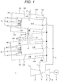
- FIG. 1 shows a part of the gas turbine according to the first embodiment of the present invention.
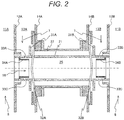
- Fig. 2 shows the configuration of a crossfire tube assembly shown in Fig. 1 .
- Fig. 3A shows the vicinity of air holes of the crossfire tube assembly shown in Fig. 1 and Fig. 2 .
- Fig. 3B is an enlarged diagram showing the vicinity of a guide ring 34A and an air hole 33C shown in Fig. 3A .
- Fig. 4 is a partial diagramof a crossfire tube assembly in a conventional example compared with the present invention. Fig. 4 is explained in comparison with Fig. 3A .
- a gas turbine 1 is configured by a compressor 2, combustors 3A and 3B, a turbine 4, and a generator 5.
- a drive shaft 6 connects the compressor 2, the turbine 4, and the generator 5.
- Air (combustion air) 7 compressed by the compressor 2 is mixed with fuel 15 by the combustors 3A and 3B to burn and change to a high-temperature and high-pressure combustion exhaust gas8. Energy is collected by the turbine 4. Electric power is generated by the generator 5.
- the combustor head portions 9A and 9B of the combustors 3A and 3B are disposed on the compressor 2 side.
- the combustor tail portions 10A and 10B of the combustors 3A and 3B are disposed on the turbine 4 side.
- the combustors 3A and 3B are configured by combustion chambers 11A and 11B, partition walls (liners) 12A and 12B configuring the combustion chambers, combustion air channels 13A and 13B, and outer circumferential partition walls 14A and 14B in order from the center side toward the outer circumference side.
- the combustion air 7 discharged from the compressor 2 reverses (turns) a flowing direction at the combustor tail portions 10A and 10B of the combustors, passes through the combustion air channels 13A and 13B, and flows to the combustor head portions 9A and 9B of the combustors.
- the combustion air 7 reverses (turns) the flowing direction again at the combustor head portions 9A and 9B of the combustors and is mixed with the fuel 15 supplied from the outside at the combustor head portions 9A and 9B to burn in the combustion chambers 11A and 11B.
- the combustion exhaust gas 8 flows into the turbine 4 from the combustor tail portions 10A and 10B of the combustors.
- a drive shaft can also be divided into a plurality of drive shafts and provided.
- the drive shaft 6 can also be used for driving of another rotating body instead of the generator 5.
- an ignitor 17 is provided in the combustor 3A.
- a crossfire tube assembly 20 is connected between the combustors 3A and 3B.
- the crossfire tube assembly 20 is configured by a double pipe of an inner tube 21 and an outer tube 22.
- the inner tube 21 connects the partition walls (the liners) 12A and 12B.
- a combustion exhaust gas 16 in the combustion chambers 11A and 11B can circulate in the inner tube 21.
- the outer tube 22 is connected to the outer circumferential partition walls 14A and 14B of the combustion air channels 13A and 13B.
- the combustion air 7 can circulate in the outer tube 22.
- a mixture of the fuel 15 and the combustion air 7 in the combustion chamber 11A is ignited by the ignitor 17 set in the combustor 3A.
- Pressure in the combustion chamber 11A is increased by generation of a combustion exhaust gas.
- the high-temperature combustion exhaust gas 16 is sent into the combustion chamber 11B from the combustion chamber 11A through the inner tube 21 that connects the combustion chambers 11A and 11B.
- the mixture of the fuel 15 and the combustion air 7 is ignited by the high-temperature combustion exhaust gas 16 flowed through the inner tube 21.
- the combustors adjacent to each other via the crossfire tube assembly 20 are sequentially ignited, whereby all the combustors can be ignited.
- Stoppers 31A and 31B for positioning are attached to the inner tube 21 of the crossfire tube assembly shown in Fig. 2 .
- the inner tube 21 is positioned by combining the stoppers 31A and 31B with retainers 32A and 32B.
- the retainers 32A and 32B are elastic bodies. Even if thermal deformation and vibration occur during the operation of the gas turbine, displacement is absorbed by the elastic bodies.
- the inner tube 21 is fixed to the combustors while stress generated in the inner tube 21 of the crossfire tube assembly is reduced.
- air holes 33 (33A to 33D) for introducing a part of the combustion air 7 into the inner tube 21 are provided.
- Guide rings 34A and 34B are respectively provided in positions opposed to the axial direction of the air holes 33 (33A to 33D).
- the configuration of the vicinity of the air holes 33A and 33C is shown in Fig. 3A .
- the guide rings 34A and 34B are cylinders having a circular shape concentric with the inner tube 21.
- the guide rings 34A and 34B configure annular spaces 35 between the guide rings 34A and 34B and the inner tube 21.
- One side (one end portion) of the guide ring 34A is connected to a partition wall configuring the inner tube 21 to be a closed end 36.
- the other side (the other end) of the guide ring 34A is an open end 37 connected to a space 25 of the inner tube 21.
- Aplurality of air holes 33 (33A to 33D) are provided in the circumferential direction of the inner tube 21.
- FIG. 3A two holes 33A and 33C among the air holes 33 are shown.
- the hole 33A on the upper side is drilled in the radial direction of the inner tube 21.
- the hole 33C on the lower side is drilled to tilt toward the closed end 36.
- Fig. 4 showing a conventional example compare with Fig. 3 , both of air holes 43A and 43C are drilled in the radial direction of the inner tube 21.
- the outer surface of the guide ring 34A is cooled by the current of the air.
- the inner circumference side of the guide ring 34A is heated by the current of the high-temperature gas (the combustion exhaust gas 16). Therefore, cooling from the outer surface needs to be facilitated as in the inner tube 21.
- so-called impingement cooling for obtaining high cooling performance according to collision of the current of the air acts on the outer circumferential surface of the guide ring 34A opposed to the air holes 43A and 43C.
- the cooling less easily works because the closed end 36 side is away from the currents 44A and 44C of the air.
- the temperature of the guide ring 34A rises. That is, in the conventional example shown in Fig. 4 , the currents 44A and 44C of the air less easily flow to the closed end 36 side. Therefore, the temperature on the closed end 36 side of the guide ring 34A sometimes rises.
- the closed end 36 side of the annular space 35 usually has length twice to three times of the diameter of the air holes 43. The temperature on the closed end 36 side of the guide rings 34 sometimes rises.
- the hole 33A on the upper side is drilled in the radial direction of the inner tube 21 and the hole 33C on the lower side is drilled to tilt toward the closed end 36.
- the drilling direction is changed for each of the air holes 33.
- the holes 33A and 33C are alternately formed in the circumferential direction of the inner tube 21.
- the air flowing in from the air hole 33C drilled to tilt with respect to the inner tube 21 has a flow velocity component directed toward the closed end 36 side according to the shape of the air hole. Therefore, the air once flows to the closed end 36 side, circulates in the annular space 35 near the closed end 36, and is thereafter discharged to the space 25 in the inner tube from the open end 37.
- a portion on which so-called impingement cooling for obtaining high cooling performance according to collision of the current of the air acts expands to the closed end 36 side of the air hole 33C.
- the portion on which the impingement cooling acts is formed in a wide range in the axial direction of the inner tube 21 centering on the air holes 33. Since a current 24C of the air flows to the closed end 36 side, a portion cooled by the current 24C of the air flowing in from the air holes expands to the annular space 35.
- the air holes 33A and 33C having different drilling angles are alternately provided.
- the angles and the directions of the holes can be adjusted as appropriate.
- the air holes 33C, the drilling direction of which is changed may be provided at a ratio of 2 to 1. It is important to form a current for circulating the air near the closed end 36. The effect explained above is obtained if the air hole 33C drilled toward the closed end 36 is included.
- length L of the space on the closed end 36 side of the air hole 33C is set to three times or more as larger as a diameter d of the air hole 33C (L ⁇ 3d).
- FIG. 5 A modification of the crossfire tube assembly shown in Fig. 2 is shown in Fig. 5 .
- the one inner tube 21 is provided and the vicinities of both the ends are fixed to the outer tube 22 of the combustor.
- flexibility increases with respect to thermal deformation in the axial direction of the inner tubes and fluctuation in the distance between the inner tubes and the outer tube 22. Therefore, it is possible to reduce stress acting on the inner tubes. Besides, since the length of the inner tubes decreases, assembly is easy.
- the first embodiment of the present invention by combining the inner tubes in which the drilling directions of the air holes 33 are changed, it is possible to achieve both of cooling and prevention of thermal deformation and fire damage of the crossfire tube assembly and a reduction in manufacturing cost due to the easiness of the assembly.
- a gas turbine according to a second embodiment of the present invention is explained with reference to Fig. 6A .
- the gas turbine according to the second embodiment is characterized in that, in the gas turbine according to the first embodiment explained above, an obstacle (a protrusion section) 51 is provided against a current of the air flowing in the annular space 35 in a part of the outer surface of the guide ring 34A provided in the crossfire tube assembly 20. Therefore, as shown in Fig. 6A , action of the obstacle 51 is mainly explained.
- the other portions are the same as the portions in the first embodiment. Therefore, detailed explanation of the portions is omitted.
- the second embodiment of the present invention is characterized in that the obstacle 51 is provided on the open end 37 side of the air hole 33C.
- the second embodiment includes a case where, as shown in Fig. 6A , the obstacle 51 is provided in the air hole 33C, which is a part of the air holes, and is not provided in, for example, the air hole 33A.
- a current 54C of the air flowed into the annular space 35 is suppressed from flowing to the open end 37 side by the obstacle 51. Therefore, the current 54C of the air once flows to the closed end 36 side, circulates in the annular space 35 near the closed end 36, and is thereafter discharged from the open end 37 to the space 25 in the inner tube. A portion on which so-called impingement cooling for obtaining high cooling performance according to collision of the current of the air acts expands to the closed end 36 side of the air hole 33C.
- a current 54A of the air flowed into the annular space 35 flows into the space 25 in the inner tube from the open end 37.
- the cooling range on the outer surface of the guide ring 34A expands, it is possible to cool the crossfire tube assembly including the guide ring 34A and reliability is improved. Since it is possible to cool the crossfire tube assembly with a smaller cooling air amount, it is possible to reduce a cooling air amount, cool the crossfire tube assembly without lowering the temperature of the combustion exhaust gas passing through the crossfire tube assembly during the ignition, and prevent thermal deformation and fire damage of the crossfire tube assembly. Since margins for fixing of the guide ring 34A and adjustment of the positions of the guide ring 34A and the air holes 33 (33A to 33D) are formed by the space on the closed end 36 side of the annular space 35, it is possible to suppress accuracy necessary for machining and machining cost.
- the structure in the second embodiment of the present invention can also be applied to the crossfire tube assembly in which the inner tube is divided as shown in Fig. 5 .
- the obstacle 51 on the outer surface of the guide ring and combining the divided inner tubes shown in Fig. 5 it is possible to achieve both of cooling and prevention of thermal deformation and fire damage of the crossfire tube assembly and a reduction in manufacturing cost due to easiness of assembly.
- Table 1 An example of evaluation of the temperature of the guide ring 34A in the crossfire tube assembly ( Fig. 6A ) according to the second embodiment and the conventional crossfire tube assembly ( Fig. 4 ) is shown in Table 1.
- the air having temperature of 260°C and flow velocity of 20 m/s was fed from an inlet of the inner tube 21 under a condition of the atmospheric pressure, the air having temperature of 10°C was supplied to the outer tube side, and cooling air was caused to flow in from the air holes.
- Temperatures of the guide ring 34A were respectively measured in two places of the closed end 36 and the open end 37. Higher temperature was presented.
- a condition of the length of the annular space 35 is that the length on the closed end 36 side is 29 of the inner diameter of the inner tube 21 and the length on the open end side is 59% of the inner diameter of the inner tube 21.
- the obstacle 51 was provided on the outer surface of the guide ring 34A on the open end 37 side of holes of one third of the air holes 33.
- the temperature of high-temperature gas flowing into the inner tube 21 is as low as 260°C.
- high-temperature gas of approximately 1200°C or more flows in. Therefore, a temperature difference is 100°C or more. It is predicted that the temperature on the closed end 36 side in the conventional example ( Fig. 4 ) reaches 600°C or more to be temperature at which fire damage is likely to occur.
- Table 1 Target Temperature of the closed end 36 Temperature of the open end 37 Conventional example ( Fig. 4 ) 138°C 115°C Second embodiment ( Fig. 6A ) 98°C 115°C
- FIG. 6B is a modification of Fig. 6A and is an embodiment in which both of the air hole 33C drilled to tilt toward the closed end 36 in the first embodiment ( Fig. 3A ) and the obstacle 51 in the second embodiment ( Fig. 6A ) are combined.
- it can be expected to further improve the cooling effect in the annular space 35 by complexly providing the air hole 33C drilled to tilt as shown in Fig. 6B and the obstacle 51 between the air hole 33C and the open end 37.
- FIG. 7 An example of a gas turbine according to a third embodiment of the present invention is shown in Fig. 7 .
- a passage throttling member (a protrusion section) 60 is provided in a space surrounded by the inner tube 21 and the outer tube 22.
- the passage throttling member 60 narrows the space between the inner tube 21 and the outer tube 22 and, when the combustion air 7 flows, works as resistance to prevent the combustion air 7 from easily flowing between the combustion air channels 13A and 13B.
- the air holes 33C and 33D are respectively provided to tilt to the closed end 36 side. Therefore, as explained above, since the cooling range on the outer surfaces of the guide rings 34A and 34B expands, it is possible to cool the crossfire tube assembly including the guide rings 34A and 34B and reliability is improved. Since it is possible to cool the crossfire tube assembly with a smaller cooling air amount, it is possible to reduce a cooling air amount, cool the crossfire tube assembly without lowering the temperature of the combustion exhaust gas passing through the crossfire tube assembly during ignition, and prevent thermal deformation and fire damage of the crossfire tube assembly.
- margins for fixing of the guide rings 34A and 34B and adjustment of the positions of the guide rings 34A and 34B and the air holes 33 are formed by the space on the closed end 36 side of the annular space 35, it is possible to suppress accuracy necessary for machining and machining cost.
- the passage throttling member 60 since the passage throttling member 60 is provided in the space surrounded by the inner tube 21 and the outer tube 22, the combustion air 7 less easily flows between the combustion air channels 13A and 13B. On the other hand, the combustion air 7 flows into the space in the outer tube 22. Therefore, in the outer tube 22, the combustion air forms currents indicated by arrows 61A and 61B. The currents of the air along the surface of the inner tube 21 reverse a flowing direction in the passage throttling member 60 and form circulating currents. The air circulates in the space in the outer tube 22, whereby convection heat transfer is facilitated and cooling of the inner tube 21 proceeds.
- the passage throttling member 60 can also be applied to the gas turbines according to the first embodiment and the second embodiment. In that case, an effect same as the effect in the third embodiment ( Fig. 7 ) is obtained.
- the present invention is not limited to the embodiments explained above and includes various modifications.
- the embodiments are explained in detail in order to clearly explain the present invention.
- the embodiments are not always limited to embodiments including all the components explained above.
- a part of the components of a certain embodiment can be substituted with the components of another embodiment.
- the components of another embodiment can also be added to the components of a certain embodiment.
- the other components can be added to, deleted from, and substituted with a part of the components of the embodiments.
Landscapes
- Engineering & Computer Science (AREA)
- Chemical & Material Sciences (AREA)
- Combustion & Propulsion (AREA)
- Mechanical Engineering (AREA)
- General Engineering & Computer Science (AREA)
- Turbine Rotor Nozzle Sealing (AREA)
- Pre-Mixing And Non-Premixing Gas Burner (AREA)
Abstract
Description
- The present invention relates to a structure of a gas turbine combustor and, more particularly, to a combustor structure of a multi-can type gas turbine including a plurality of combustors that mix and burn fuel and the air, the combustors being connected by a crossfire tube assembly.
- There is a form called multi-can type gas turbine including multi-can type gas turbine combustors (hereinafter described as combustors) with respect to one gas turbine. Usually, in the multi-can type combustor, the combustors are annularly disposed around the gas turbine, an ignitor is set in one or several combustors, and the other remaining combustors do not include individual ignitors. Ignition of the combustors not including the ignitors is carried out through a pipe that connects the combustors adjacent to one another called crossfire tube assembly. When the gas turbine is started, a system for first igniting the combustor (s) in which the ignitor(s) is (are) set and igniting the adjacent combustors via the crossfire tube assembly to ignite all the combustors is adopted.
- In general, the crossfire tube assembly is configured by a double pipe of an inner tube and an outer tube. The inner tube connects combustion chambers of the adjacent combustors, circulates a high-temperature combustion exhaust gas, and performs flame propagation. The outer tube is provided on the outer circumference side of the inner tube, connects channels of the air for fuel of the adjacent combustors, and reduces a pressure difference between an inner tube inner side and an inner tube outer side to play a role of protecting the inner tube.
- The crossfire tube assembly is a constituent component necessary for the ignition operation explained above and needs to surely carry out the ignition. Since the crossfire tube assembly is exposed to the high-temperature combustion exhaust gas, prevention of thermal deformation and fire damage needs to be examined. A method of positioning in combining the combustors, a method of coping with deformation, and the like also need to be examined.
- As the background art of this technical field, for example, there are techniques disclosed in
Patent Document 1 to Patent Document 3.Patent Document 1 discloses a technique for cooling a crossfire tube assembly and preventing fire damage.Patent Document 2 discloses a positioning method in connecting combustors and a technique for cooling a crossfire tube assembly and preventing fire damage. Patent Document 3 discloses a technique for diffusing, with a plurality of flow disseminators provided with respect to a plurality of cooling holes provided in a combustor section, which is a partition wall configuring a combustion chamber of a combustor, to be aligned with the cooling holes, cooling air flowing through the cooling holes. -
- [Patent Document 1]
-
JP-A-10-339440 - [Patent Document 2]
-
JP-A-11-14056 - [Patent Document 3]
-
JP-A-2010-106829 - The crossfire tube assembly feeds the combustion exhaust gas to the combustors before ignition to ignite the combustors making use of a pressure difference that occurs between the combustors after ignition completion and the combustors before ignition adjacent to the combustors. If the ignition ends in all the combustors and air amounts, fuel amounts, and pressures of the respective combustors are the same, there is no pressure difference between the combustors and there is no current of the combustion exhaust gas that circulates in the crossfire tube assembly. In this case, a time in which the high-temperature combustion exhaust gas circulates in the crossfire tube assembly is only a short time during the ignition.
- However, actually, fluctuation occurs in the air amounts, the fuel amounts, the pressures, and combustion states in each of the combustors. Therefore, in some case, a pressure difference occurs between the adjacent combustors and the high-temperature combustion exhaust gas continues to circulate through the crossfire tube assembly. At this point, the crossfire tube assembly continues to be exposed to the high-temperature combustion exhaust gas to have high temperature. Therefore, the crossfire tube assembly needs to be cooled for prevention of thermal deformation and fire damage of the crossfire tube assembly.
- As one of methods of cooling the crossfire tube assembly, there is a method of guiding a part of the combustion air having temperature lower than the temperature of the high-temperature combustion exhaust gas into the crossfire tube assembly through holes (airholes) provided in the crossfire tube assembly to cool the crossfire tube assembly. The wall surface of the inner tube is cooled by causing the combustion air in the outer tube to flow into the inner tube from the air holes provided on the wall surface of the inner tube of the crossfire tube assembly.
- When cooling the wall surface of the inner tube, if a guide ring having a circular shape concentric with the inner tube is provided in a position opposed to the axial direction of the air holes in the inner tube inside, one end face is closed, and an end face on one side is opened to the inner tube inside, the air flowing in from the air holes flows along the inner circumferential wall surface of the inner tube from the open end face of the guide ring. Since the low-temperature cooling air flows along the inner tube wall surface, it is possible to prevent the inner tube wall surface from being exposed to the high-temperature combustion exhaust gas and prevent thermal deformation and fire damage of the crossfire tube assembly.
- However, in the configuration explained above, the inner circumference side of the guide ring is exposed to the current of the high-temperature combustion exhaust gas. The guide ring is cooled by a so-called impingement effect at the time when the air circulating from the air holes collides with the outer circumference side of the guide ring. However, a cooling range of the air is limited to the peripheries of the air holes. In particular, the air less easily flows on the closed end side where an end portion is closed in an annular space between the inner tube and the guide ring. Therefore, the temperature of the guide ring rises. There is a risk of thermal deformation and fire damage.
- To lower the temperature of the guide ring, there are a method of increasing the sectional area of the air holes to increase a cooling air amount and a method of reducing the length of the guide ring to narrow a range exposed to the current of the high-temperature combustion exhaust gas. However, in the method of increasing the cooling air amount, it is likely that the temperature of the combustion exhaust gas passing through the crossfire tube assembly is lowered during ignition of the gas turbine combustor to hinder flame propagation. In the method of reducing the length of the guide ring, an effect of the current of the air being guided by the guide ring decreases and the cooling range of the inner tube is narrowed. There is a problem in that positions where the air holes are provided are limited and machining cost increases.
- The present invention has been devised in view of the problems and an object of the present invention is to provide a multi-can type gas turbine including a plurality of combustors. The gas turbine cools a crossfire tube assembly without lowering the temperature of a combustion exhaust gas passing through the crossfire tube assembly during ignition of a gas turbine combustor and prevents thermal deformation and fire damage of the crossfire tube assembly.
- In order to solve the problem, a gas turbine according to the present invention is a multi-can type gas turbine including a plurality of combustors. The gas turbine is applied to a form in which the combustors adjacent to one another are connected by a crossfire tube assembly and the combustors are ignited by flame propagation. Further, the crossfire tube assembly is configured by a double pipe and configured by an inner tube that connects combustion chambers of the adjacent combustors and an outer tube that covers the inner tube and connects combustion air channels of the adjacent combustors. Further, holes (air holes) for introducing the air into the inside are provided in the inner tube. A guide ring having a circular shape concentric with the inner tube is provided in a position opposed to the axial direction of the air holes. One end face is closed and an end face on one side (the other end face) is opened to the inner tube inside.
- In the gas turbine including the crossfire tube assembly having the configuration explained above, a part of the air holes is drilled toward the closed end side.
- Besides changing the drilling direction of the air holes, an obstacle for suppressing the air supplied from the air holes from flowing and guiding the air to the closed end face may be provided in a position opposed to the air holes on the outer circumference side of the guide ring.
- Note that, in the gas turbine including the crossfire tube assembly having the configuration explained above, an annular space may be provided between a partition wall of the inner tube and the guide ring. The annular space on the closed end side may be expanded to set the distance between the air holes and the closed end to be three times or more as large as the diameter of the air holes.
- According to the present invention, it is possible to facilitate cooling of the crossfire tube assembly under a condition in which an amount of cooling air circulated into the inner tube of the crossfire tube assembly for cooling is small. Therefore, it is possible to suppress, during ignition of the gas turbine combustor, the temperature of a high-temperature combustion exhaust gas passing through the crossfire tube assembly from falling because of mixing with the cooling air and surely carry out flame propagation between the combustors. It is possible to prevent thermal deformation and fire damage of the crossfire tube assembly through the cooling of the crossfire tube assembly.
- In the present invention, the guide ring having the circular shape concentric with the inner tube is provided in the position opposed to the axial direction of the air holes provided in the inner tube, the one end face is closed, and the end face on the one side is opened to the inner tube inside. Then, the air flowing in from the air holes flows along the inner circumferential wall surface of the inner tube from the opened end face of the guide ring. Since the low-temperature cooling air flows along the inner tube wall surface, it is possible to prevent the crossfire tube assembly from being exposed to the high-pressure combustion exhaust gas and prevent thermal deformation and fire damage of the crossfire tube assembly.
- In this case, a part of the air holes is drilled toward the closed end side to forcibly feed a part of the air to the closed end side and cause a current of the air on the closed end side to facilitate the cooling of the guide ring. Since drilling directions of the air holes are different for each of the holes, a range cooled by a so-called impingement effect at the time when the air circulating from the air holes collides with the outer circumference side of the guide ring expands to the axial direction of the guide ring. Therefore, the guide ring is easily cooled. The inner circumference side of the guide ring is exposed to the high-temperature combustion exhaust gas. However, since the range cooled by the impingement effect on the outer circumference side of the guide ring expands and the current of the air on the closed end side is generated, it is possible to prevent thermal deformation and fire damage of the crossfire tube assembly including the guide ring with a small air amount.
- When the obstacle for guiding the air supplied from the air holes to the closed end face is provided in the position opposed to the air holes on the outer circumference side of the guide ring, the same effect is obtained. That is, by guiding a part of the air to the closed end side with the obstacle, a current of the air is caused on the closed end side to facilitate cooling of the guide ring. The range cooled by the so-called impingement effect at the time when the air circulating from the air holes collides with the outer circumference side of the guide ring expands to the closed end side of the guide ring. Therefore, it is possible to prevent thermal deformation and fire damage of the crossfire tube assembly including the guide ring with a small air amount.
- Note that, in the annular space between the partition wall of the inner tube and the guide ring, if the distance between the air holes and the closed end is set to three times or more as large as the diameter of the air holes, the air flowing to the closed end side in the air flowing in from the air holes easily reverses and flows out from the open end side. Therefore, an amount of the air flowing to the closed end side increases. It is easy to cool the closed end side of the guide ring.
- Problems, configurations, and effects other than these explained above are clarified by the following explanation of embodiments.
-
-
Fig. 1 is a schematic diagram showing a schematic configuration of a gas turbine combustor according to an embodiment of the present invention. -
Fig. 2 is a schematic diagram showing the configuration of a crossfire tube assembly in the gas turbine combustor shown inFig. 1 . -
Fig. 3A is a schematic diagram showing the configuration of air holes for cooling in the crossfire tube assembly shown inFig. 2 . -
Fig. 3B is a schematic diagram showing a positional relation between (dimensions of) a part of the air holes for cooling and a guide ring shown inFig. 3A . -
Fig. 4 is a schematic diagram showing the configuration of air holes for cooling of a conventional crossfire tube assembly in comparison with the crossfire tube assembly according to the embodiment of the present invention shown inFig. 3A . -
Fig. 5 is a schematic diagram showing the configuration of the crossfire tube assembly according to the embodiment of the present invention. -
Fig. 6A is a schematic diagram showing the configuration of air holes for cooling in a crossfire tube assembly according to an embodiment of the present invention. -
Fig. 6B is a schematic diagram showing the configuration of the air holes for cooling in the crossfire tube assembly according to the embodiment of the present invention. -
Fig. 7 is a schematic diagram showing the configuration of a crossfire tube assembly according to an embodiment of the present invention. - Gas turbines according to embodiments of the present invention are explained below with reference to the drawings. Note that, in the explanation, the same reference numerals and signs are used for the same components and explanation of the components is sometimes omitted.
- A gas turbine according to a first embodiment of the present invention is explained with reference to
Fig. 1 to Fig. 4 .Fig. 1 shows a part of the gas turbine according to the first embodiment of the present invention.Fig. 2 shows the configuration of a crossfire tube assembly shown inFig. 1 .Fig. 3A shows the vicinity of air holes of the crossfire tube assembly shown inFig. 1 andFig. 2 .Fig. 3B is an enlarged diagram showing the vicinity of aguide ring 34A and anair hole 33C shown inFig. 3A .Fig. 4 is a partial diagramof a crossfire tube assembly in a conventional example compared with the present invention.Fig. 4 is explained in comparison withFig. 3A . - First, a role and a problem of the crossfire tube assembly are explained with reference to
Fig. 1 andFig. 2 . Then, a difference between content of the first embodiment of the present invention and the conventional example is explained with reference toFig. 3 andFig. 4 . - In
Fig. 1 , agas turbine 1 is configured by acompressor 2,combustors turbine 4, and agenerator 5. Adrive shaft 6 connects thecompressor 2, theturbine 4, and thegenerator 5. Air (combustion air) 7 compressed by thecompressor 2 is mixed withfuel 15 by thecombustors turbine 4. Electric power is generated by thegenerator 5. - The
combustor head portions combustors compressor 2 side. Thecombustor tail portions combustors turbine 4 side. Thecombustors combustion chambers combustion air channels circumferential partition walls combustion air 7 discharged from thecompressor 2 reverses (turns) a flowing direction at thecombustor tail portions combustion air channels combustor head portions - The
combustion air 7 reverses (turns) the flowing direction again at thecombustor head portions fuel 15 supplied from the outside at thecombustor head portions combustion chambers combustion exhaust gas 8 flows into theturbine 4 from thecombustor tail portions - Note that, to simplify explanation, two combustors are shown in
Fig. 1 . However, the same applies when thegas turbine 1 includes three or more combustors. InFig. 1 , thecompressor 2, theturbine 4, and thegenerator 5 are connected to onedrive shaft 6. However, a drive shaft can also be divided into a plurality of drive shafts and provided. Thedrive shaft 6 can also be used for driving of another rotating body instead of thegenerator 5. - In the gas turbine shown in
Fig. 1 , anignitor 17 is provided in thecombustor 3A. Acrossfire tube assembly 20 is connected between thecombustors crossfire tube assembly 20 is configured by a double pipe of aninner tube 21 and anouter tube 22. Theinner tube 21 connects the partition walls (the liners) 12A and 12B. Acombustion exhaust gas 16 in thecombustion chambers inner tube 21. Theouter tube 22 is connected to the outercircumferential partition walls combustion air channels combustion air 7 can circulate in theouter tube 22. - During ignition of the gas turbine, a mixture of the
fuel 15 and thecombustion air 7 in thecombustion chamber 11A is ignited by theignitor 17 set in thecombustor 3A. Pressure in thecombustion chamber 11A is increased by generation of a combustion exhaust gas. However, since ignition is not performed in thecombustion chamber 11B yet, pressure in thecombustion chamber 11B is low. Therefore, the high-temperaturecombustion exhaust gas 16 is sent into thecombustion chamber 11B from thecombustion chamber 11A through theinner tube 21 that connects thecombustion chambers combustion chamber 11B, the mixture of thefuel 15 and thecombustion air 7 is ignited by the high-temperaturecombustion exhaust gas 16 flowed through theinner tube 21. The combustors adjacent to each other via thecrossfire tube assembly 20 are sequentially ignited, whereby all the combustors can be ignited. - If air amounts, fuel flow rates, and pressures of the respective combustors are the same, there is no pressure difference between the combustors when the ignition ends in all the combustors. In this case, there is no current of the high-temperature
combustion exhaust gas 16 circulating in theinner tube 21 of thecrossfire tube assembly 20. Time in which the high-temperaturecombustion exhaust gas 16 circulates in theinner tube 21 is only a short time during the ignition. However, actually, fluctuation sometimes occurs in the air amounts, the fuel flow rates, the pressures, and combustion states in each of the combustors. In this case, the high-temperaturecombustion exhaust gas 16 sometimes continues to circulate in theinner tube 21 according to a pressure difference between theadjacent combustors inner tube 21 has high temperature because the high-temperaturecombustion exhaust gas 16 circulates. Deformation and damage easily occur in operation for a long time. Theinner tube 21 needs to be cooled for prevention of the deformation and the damage. - Details of the crossfire tube assembly are shown in
Fig. 2 .Stoppers inner tube 21 of the crossfire tube assembly shown inFig. 2 . Theinner tube 21 is positioned by combining thestoppers retainers retainers inner tube 21 is fixed to the combustors while stress generated in theinner tube 21 of the crossfire tube assembly is reduced. - In the
inner tube 21 of the crossfire tube assembly, air holes 33 (33A to 33D) for introducing a part of thecombustion air 7 into theinner tube 21 are provided. Guide rings 34A and 34B are respectively provided in positions opposed to the axial direction of the air holes 33 (33A to 33D). - The configuration of the vicinity of the
air holes Fig. 3A . The guide rings 34A and 34B are cylinders having a circular shape concentric with theinner tube 21. The guide rings 34A and 34B configureannular spaces 35 between the guide rings 34A and 34B and theinner tube 21. One side (one end portion) of theguide ring 34A is connected to a partition wall configuring theinner tube 21 to be aclosed end 36. The other side (the other end) of theguide ring 34A is anopen end 37 connected to aspace 25 of theinner tube 21. Aplurality of air holes 33 (33A to 33D) are provided in the circumferential direction of theinner tube 21. InFig. 3A , twoholes hole 33A on the upper side is drilled in the radial direction of theinner tube 21. Thehole 33C on the lower side is drilled to tilt toward theclosed end 36. On the other hand, inFig. 4 showing a conventional example compare withFig. 3 , both ofair holes inner tube 21. - In the conventional example shown in
Fig. 4 , first,currents inner tube 21 from air holes 43 (43A and 43C) collide with the outer circumferential surface of theguide ring 34A opposed to the air holes. A flowing direction changes toward theopen end 37 and thecurrents inner tube 21. A layer of thecurrents inner tube 21 and theinner tube 21 of the crossfire tube assembly to suppress heat transfer from the current of the high-temperature gas (the combustion exhaust gas 16) to theinner tube 21 of the crossfire tube assembly and suppress a temperature rise of theinner tube 21. Such a cooling system is called film cooling because thecurrents inner tube 21. - The outer surface of the
guide ring 34A is cooled by the current of the air. On the other hand, the inner circumference side of theguide ring 34A is heated by the current of the high-temperature gas (the combustion exhaust gas 16). Therefore, cooling from the outer surface needs to be facilitated as in theinner tube 21. When being cooled by thecurrents guide ring 34A opposed to theair holes - Cooling by the
currents air holes open end 37. On the other hand, on theclosed end 36 side from theair holes closed end 36 side is away from thecurrents guide ring 34A rises. That is, in the conventional example shown inFig. 4 , thecurrents closed end 36 side. Therefore, the temperature on theclosed end 36 side of theguide ring 34A sometimes rises. - Therefore, it is desirable to narrow a space on the
closed end 36 side of theannular space 35. However, when fixing of the guide rings 34 (34A and 34B) and adjustment of the positions of the guide rings 34 and the air holes 43 (43A to 43D) are taken into account, a space is formed on theclosed end 36 side of theannular space 35. When it is attempted to narrow the space, more machining accuracy is required for the fixing of the guide rings 34 and the adjustment of the positions of the guide rings 34 and the air holes 43 (43A to 43D) and cost increases. Therefore, theclosed end 36 side of theannular space 35 usually has length twice to three times of the diameter of the air holes 43. The temperature on theclosed end 36 side of the guide rings 34 sometimes rises. - On the other hand, in the first embodiment of the present invention shown in
Fig. 3A , as shown inFig. 3A , among the air holes 33, thehole 33A on the upper side is drilled in the radial direction of theinner tube 21 and thehole 33C on the lower side is drilled to tilt toward theclosed end 36. The drilling direction is changed for each of the air holes 33. For example, theholes inner tube 21. - The air flowing in from the
air hole 33C drilled to tilt with respect to theinner tube 21 has a flow velocity component directed toward theclosed end 36 side according to the shape of the air hole. Therefore, the air once flows to theclosed end 36 side, circulates in theannular space 35 near theclosed end 36, and is thereafter discharged to thespace 25 in the inner tube from theopen end 37. A portion on which so-called impingement cooling for obtaining high cooling performance according to collision of the current of the air acts expands to theclosed end 36 side of theair hole 33C. In this embodiment, by changing the drilling direction of the air holes, the portion on which the impingement cooling acts is formed in a wide range in the axial direction of theinner tube 21 centering on the air holes 33. Since a current 24C of the air flows to theclosed end 36 side, a portion cooled by the current 24C of the air flowing in from the air holes expands to theannular space 35. - Since a cooling range on the outer surface of the
guide ring 34A expands, it is possible to cool the crossfire tube assembly including theguide ring 34A and reliability is improved. Since it is possible to cool the crossfire tube assembly with a smaller cooling air amount, it is possible to reduce a cooling air amount, cool the crossfire tube assembly without lowering the temperature of the combustion exhaust gas passing through the crossfire tube assembly during the ignition, and prevent thermal deformation and fire damage of the crossfire tube assembly. Since margins for the fixing of theguide ring 34A and the adjustment of the positions of theguide ring 34A and the air holes 33 (33A to 33D) are formed by the space on theclosed end 36 side of theannular space 35, it is possible to suppress accuracy necessary for machining and machining cost. - In the embodiment shown in
Fig. 3A , theair holes air holes 33A, theair holes 33C, the drilling direction of which is changed, may be provided at a ratio of 2 to 1. It is important to form a current for circulating the air near theclosed end 36. The effect explained above is obtained if theair hole 33C drilled toward theclosed end 36 is included. - In the first embodiment of the present invention shown in
Fig. 3A , as shown inFig. 3B , length L of the space on theclosed end 36 side of theair hole 33C is set to three times or more as larger as a diameter d of theair hole 33C (L≥3d). By expanding a portion between the air holes and the closed end in the annular space between the partition wall of the inner tube and the guide ring, in the air flowing in from the air holes, the air flowing to the closed end side reverses and easily flows out from the open end side. Therefore, an amount of the air flowing to the closed end side increases. It is easy to cool the closed end side of the guide ring. - A modification of the crossfire tube assembly shown in
Fig. 2 is shown inFig. 5 . In this embodiment shown inFig. 1 to Fig. 3B , the oneinner tube 21 is provided and the vicinities of both the ends are fixed to theouter tube 22 of the combustor. However, as shown inFig. 5 , it is also possible to divide the inner tube intoinner tubes portion 48 as a fitting structure. By forming theinner tubes outer tube 22. Therefore, it is possible to reduce stress acting on the inner tubes. Besides, since the length of the inner tubes decreases, assembly is easy. - As explained above, according to the first embodiment of the present invention, by combining the inner tubes in which the drilling directions of the air holes 33 are changed, it is possible to achieve both of cooling and prevention of thermal deformation and fire damage of the crossfire tube assembly and a reduction in manufacturing cost due to the easiness of the assembly.
- A gas turbine according to a second embodiment of the present invention is explained with reference to
Fig. 6A . Note that the gas turbine according to the second embodiment is characterized in that, in the gas turbine according to the first embodiment explained above, an obstacle (a protrusion section) 51 is provided against a current of the air flowing in theannular space 35 in a part of the outer surface of theguide ring 34A provided in thecrossfire tube assembly 20. Therefore, as shown inFig. 6A , action of theobstacle 51 is mainly explained. The other portions are the same as the portions in the first embodiment. Therefore, detailed explanation of the portions is omitted. - The second embodiment of the present invention is characterized in that the
obstacle 51 is provided on theopen end 37 side of theair hole 33C. The second embodiment includes a case where, as shown inFig. 6A , theobstacle 51 is provided in theair hole 33C, which is a part of the air holes, and is not provided in, for example, theair hole 33A. - In the
air hole 33C, near which theobstacle 51 is provided, a current 54C of the air flowed into theannular space 35 is suppressed from flowing to theopen end 37 side by theobstacle 51. Therefore, the current 54C of the air once flows to theclosed end 36 side, circulates in theannular space 35 near theclosed end 36, and is thereafter discharged from theopen end 37 to thespace 25 in the inner tube. A portion on which so-called impingement cooling for obtaining high cooling performance according to collision of the current of the air acts expands to theclosed end 36 side of theair hole 33C. On the other hand, in theair hole 33A, near which theobstacle 51 is not provided, a current 54A of the air flowed into theannular space 35 flows into thespace 25 in the inner tube from theopen end 37. - As indicated by the
currents Fig. 6A , two ways of the currents of the air are formed by providing theobstacle 51 on theopen end 37 side of theair hole 33C as a part of the air holes. Therefore, the portion on which the impingement cooling acts is formed in a wide range in the axial direction of theinner tube 21 centering on the air holes 33. Since the current 54C of the air flows to theclosed end 36 side, a portion cooled by the air current 54C flowing in from the air holes expands to theannular space 35. - Since the cooling range on the outer surface of the
guide ring 34A expands, it is possible to cool the crossfire tube assembly including theguide ring 34A and reliability is improved. Since it is possible to cool the crossfire tube assembly with a smaller cooling air amount, it is possible to reduce a cooling air amount, cool the crossfire tube assembly without lowering the temperature of the combustion exhaust gas passing through the crossfire tube assembly during the ignition, and prevent thermal deformation and fire damage of the crossfire tube assembly. Since margins for fixing of theguide ring 34A and adjustment of the positions of theguide ring 34A and the air holes 33 (33A to 33D) are formed by the space on theclosed end 36 side of theannular space 35, it is possible to suppress accuracy necessary for machining and machining cost. - Further, the structure in the second embodiment of the present invention can also be applied to the crossfire tube assembly in which the inner tube is divided as shown in
Fig. 5 . As explained in the second embodiment of the present invention, by providing theobstacle 51 on the outer surface of the guide ring and combining the divided inner tubes shown inFig. 5 , it is possible to achieve both of cooling and prevention of thermal deformation and fire damage of the crossfire tube assembly and a reduction in manufacturing cost due to easiness of assembly. - An example of evaluation of the temperature of the
guide ring 34A in the crossfire tube assembly (Fig. 6A ) according to the second embodiment and the conventional crossfire tube assembly (Fig. 4 ) is shown in Table 1. In the evaluation, the air having temperature of 260°C and flow velocity of 20 m/s was fed from an inlet of theinner tube 21 under a condition of the atmospheric pressure, the air having temperature of 10°C was supplied to the outer tube side, and cooling air was caused to flow in from the air holes. Temperatures of theguide ring 34A were respectively measured in two places of theclosed end 36 and theopen end 37. Higher temperature was presented. A condition of the length of theannular space 35 is that the length on theclosed end 36 side is 29 of the inner diameter of theinner tube 21 and the length on the open end side is 59% of the inner diameter of theinner tube 21. Under the condition, in the configuration of the second embodiment, theobstacle 51 was provided on the outer surface of theguide ring 34A on theopen end 37 side of holes of one third of the air holes 33. - In Table 1, in the conventional example (
Fig. 4 ), the temperature at the end portion on theclosed end 36 side rose approximately 20°C compared with theopen end 37 side. On the other hand, in the configuration of the second embodiment (Fig. 6A ), the temperature on theclosed end 36 side fell to temperature equal to or lower than the temperature on theopen end 37 side. In the conventional example (Fig. 4 ), the temperature is considered to have risen compared with theopen end 37 side because the air less easily flows to theannular space 35 on theclosed end 36 side and cooling in this portion does not proceed. On the other hand, in the configuration of the second embodiment (Fig. 6A ), the temperature is considered to have fallen because theobstacle 51 is provided on the outer surface of theguide ring 34A, the air flows to theclosed end 36 side, and cooling proceeds. - In this test, the temperature of high-temperature gas flowing into the
inner tube 21 is as low as 260°C. However, in an actual gas turbine combustor, high-temperature gas of approximately 1200°C or more flows in. Therefore, a temperature difference is 100°C or more. It is predicted that the temperature on theclosed end 36 side in the conventional example (Fig. 4 ) reaches 600°C or more to be temperature at which fire damage is likely to occur. - [Table 1]
Table 1 Target Temperature of the closed end 36Temperature of the open end 37Conventional example ( Fig. 4 )138°C 115°C Second embodiment ( Fig. 6A )98°C 115°C - NotethatFig. 6B is a modification of
Fig. 6A and is an embodiment in which both of theair hole 33C drilled to tilt toward theclosed end 36 in the first embodiment (Fig. 3A ) and theobstacle 51 in the second embodiment (Fig. 6A ) are combined. Depending on operation conditions such as the size of the gas turbine combustor and a flow rate of the combustion air, it can be expected to further improve the cooling effect in theannular space 35 by complexly providing theair hole 33C drilled to tilt as shown inFig. 6B and theobstacle 51 between theair hole 33C and theopen end 37. - An example of a gas turbine according to a third embodiment of the present invention is shown in
Fig. 7 . In the gas turbine shown inFig. 7 , a passage throttling member (a protrusion section) 60 is provided in a space surrounded by theinner tube 21 and theouter tube 22. Thepassage throttling member 60 narrows the space between theinner tube 21 and theouter tube 22 and, when thecombustion air 7 flows, works as resistance to prevent thecombustion air 7 from easily flowing between thecombustion air channels - In
Fig. 7 , as explained in the first embodiment, theair holes closed end 36 side. Therefore, as explained above, since the cooling range on the outer surfaces of the guide rings 34A and 34B expands, it is possible to cool the crossfire tube assembly including the guide rings 34A and 34B and reliability is improved. Since it is possible to cool the crossfire tube assembly with a smaller cooling air amount, it is possible to reduce a cooling air amount, cool the crossfire tube assembly without lowering the temperature of the combustion exhaust gas passing through the crossfire tube assembly during ignition, and prevent thermal deformation and fire damage of the crossfire tube assembly. Since margins for fixing of the guide rings 34A and 34B and adjustment of the positions of the guide rings 34A and 34B and the air holes 33 (33A to 33D) are formed by the space on theclosed end 36 side of theannular space 35, it is possible to suppress accuracy necessary for machining and machining cost. - Further, in the gas turbine shown in
Fig. 7 , since thepassage throttling member 60 is provided in the space surrounded by theinner tube 21 and theouter tube 22, thecombustion air 7 less easily flows between thecombustion air channels combustion air 7 flows into the space in theouter tube 22. Therefore, in theouter tube 22, the combustion air forms currents indicated byarrows inner tube 21 reverse a flowing direction in thepassage throttling member 60 and form circulating currents. The air circulates in the space in theouter tube 22, whereby convection heat transfer is facilitated and cooling of theinner tube 21 proceeds. Note that thepassage throttling member 60 can also be applied to the gas turbines according to the first embodiment and the second embodiment. In that case, an effect same as the effect in the third embodiment (Fig. 7 ) is obtained. - Note that the present invention is not limited to the embodiments explained above and includes various modifications. For example, the embodiments are explained in detail in order to clearly explain the present invention. The embodiments are not always limited to embodiments including all the components explained above. A part of the components of a certain embodiment can be substituted with the components of another embodiment. The components of another embodiment can also be added to the components of a certain embodiment. The other components can be added to, deleted from, and substituted with a part of the components of the embodiments.
-
- 1 gas turbine
- 2 compressor
- 3A, 3B combustor
- 4 turbine
- 5 generator
- 6 drive shaft
- 7 combustion air
- 8 combustion exhaust gas
- 9A, 9B combustor head portion
-
10A 10B combustor tail portion - 11A, 11B combustion chamber
- 12A, 12B partition wall (liner)
- 13A, 13B combustion air channel
- 14A, 14B outer circumferential partition wall
- 15 fuel
- 16 combustion exhaust gas
- 17 ignitor
- 20 crossfire tube assembly
- 21, 21A, 21B inner tube
- 22 outer tube
- 23 partition wall of the inner tube
- 24, 24A, 24B, 24C, 24D current of the air
- 25 space in the inner tube
- 26 space between the inner tube and the outer tube
- 27 center axis of the crossfire tube assembly
- 31A, 31B stopper
- 32A, 32B retainer
- 33, 33A, 33B, 33C, and 33D air hole
- 34, 34A, 34B guide ring
- 35 annular space
- 36 closed end
- 37 open end
- 43, 43A, 43B, 43C, 43D air hole
- 44, 44A, 44B, 44C, 44D current of the air
- 48 divided portion
- 51 obstacle (protrusion section)
- 60 passage throttling member (protrusion section)
- 61, 61A, 61B current of the air.
Claims (10)
- A gas turbine combustor comprising a plurality of combustors (3A, 3B), the combustors adjacent to one another being connected by a crossfire tube assembly (20), the gas turbine combustor igniting the respective plurality of combustors (3A, 3B) via the crossfire tube assembly (20),
characterized in that
the crossfire tube assembly (20) includes:an inner tube (21), on an inside of which a combustion exhaust gas flows; andan outer tube (22) provided to cover the inner tube (21), the inner tube (21) includes:one end of the guide ring (34, 34A, 34B) is connected to a partition wall of the crossfire tube assembly (20) to be a closed end (36) against a current of the introduced air, and the other end of the guide ring (34, 34A, 34B) is an open end (37) opened to a space in the inner tube (21), andair holes (33, 33A, 33B, 33C, 33D) that introduce air into the inner tube (21) from an outside of the crossfire tube assembly (20); andaguidering (34, 34A, 34B) provided in a position opposed to the air holes (33, 33A, 33B, 33C, 33D) in the inner tube (21), the guide ring (34, 34A, 34B) guiding the air introduced into the inner tube (21),
at least a part of the air holes (33, 33A, 33B, 33C, 33D) is drilled to tilt to the closed end (36) side. - The gas turbine combustor according to claim 1, characterized in that a distance from centers of the air holes (33, 33A, 33B, 33C, 33D) to the closed end (36) is three times or more as large as a diameter of the air holes (33, 33A, 33B, 33C, 33D).
- The gas turbine combustor according to claim 1 or 2, characterized in that
the inner tube (21) is formed to be divisible into two cylindrical members (21A, 21B), and
one cylindrical member (21A) is fit in the other cylindrical member (21B) to configure the inner tube (21). - The gas turbine combustor according to any one of claims 1 to 3, characterized in that a protrusion section (51) that suppresses the current of the air is provided between the air holes (33, 33A, 33B, 33C, 33D) and the open end (37).
- The gas turbine combustor according to any one of claims 1 to 4, characterized in that a protrusion section (60) that suppresses the current of the air is provided between the inner tube (21) and the outer tube (22).
- A gas turbine combustor comprising a plurality of combustors (3A, 3B), the combustors adjacent to one another being connected by a crossfire tube assembly (20), the gas turbine combustor igniting the respective plurality of combustors (3A, 3B) via the crossfire tube assembly (20),
characterized in that
the crossfire tube assembly (20) includes:an inner tube (21), on an inside of which a combustion exhaust gas flows; andan outer tube (22) provided to cover the inner tube (21), the inner tube (21) includes:one end of the guide ring (34, 34A, 34B) is connected to a partition wall of the crossfire tube assembly (20) to be a closed end (36) against a current of the introduced air, and the other end of the guide ring (34, 34A, 34B) is an open end (37) opened to a space in the inner tube (21), andair holes (33, 33A, 33B, 33C, 33D) that introduce air into the inner tube (21) from an outside of the crossfire tube assembly (20); andaguidering (34, 34A, 34B) provided in a position opposed to the air holes (33, 33A, 33B, 33C, 33D) in the inner tube (21), the guide ring (34, 34A, 34B) guiding the air introduced into the inner tube (21),
a protrusion section (51) that suppresses the current of the air is provided between the air holes (33, 33A, 33B, 33C, 33D) and the open end (37). - The gas turbine combustor according to claim 6, characterized in that a distance from centers of the air holes (33, 33A, 33B, 33C, 33D) to the closed end (36) is three times or more as large as a diameter of the air holes (33, 33A, 33B, 33C, 33D).
- The gas turbine combustor according to claim 6 or 7, characterized in that
the inner tube (21) is formed to be divisible into two cylindrical members (21A, 21B), and
one cylindrical member (21A) is fit in the other cylindrical member (21B) to configure the inner tube (21). - The gas turbine combustor according to any one of claims 6 to 8, characterized in that at least a part of the air holes (33, 33A, 33B, 33C, 33D) is drilled to tilt to the closed end (36) side.
- The gas turbine combustor according to any one of claims 6 to 9,
characterized in that the protrusion section (60) that suppresses the current of the air is provided between the inner tube (21) and the outer tube (22).
Applications Claiming Priority (1)
| Application Number | Priority Date | Filing Date | Title |
|---|---|---|---|
| JP2016156416A JP6590771B2 (en) | 2016-08-09 | 2016-08-09 | Gas turbine combustor |
Publications (2)
| Publication Number | Publication Date |
|---|---|
| EP3282192A1 true EP3282192A1 (en) | 2018-02-14 |
| EP3282192B1 EP3282192B1 (en) | 2019-03-13 |
Family
ID=59383446
Family Applications (1)
| Application Number | Title | Priority Date | Filing Date |
|---|---|---|---|
| EP17182231.5A Active EP3282192B1 (en) | 2016-08-09 | 2017-07-19 | Gas turbine combustor |
Country Status (6)
| Country | Link |
|---|---|
| US (1) | US10520196B2 (en) |
| EP (1) | EP3282192B1 (en) |
| JP (1) | JP6590771B2 (en) |
| KR (1) | KR102000337B1 (en) |
| CN (1) | CN107726363B (en) |
| RU (1) | RU2669883C9 (en) |
Cited By (1)
| Publication number | Priority date | Publication date | Assignee | Title |
|---|---|---|---|---|
| US11649966B1 (en) | 2022-02-17 | 2023-05-16 | General Electric Company | Combustor with an ignition tube |
Families Citing this family (3)
| Publication number | Priority date | Publication date | Assignee | Title |
|---|---|---|---|---|
| US10161635B2 (en) * | 2014-06-13 | 2018-12-25 | Rolls-Royce Corporation | Combustor with spring-loaded crossover tubes |
| CN119778753B (en) * | 2023-10-08 | 2025-11-25 | 中国航发商用航空发动机有限责任公司 | Gas turbine and its combustion chamber |
| CN117703597B (en) * | 2024-02-06 | 2024-04-12 | 中国空气动力研究与发展中心空天技术研究所 | Microchannel high-temperature-resistant ignition device of ramjet engine, design method and preparation method |
Citations (7)
| Publication number | Priority date | Publication date | Assignee | Title |
|---|---|---|---|---|
| US5402635A (en) * | 1993-09-09 | 1995-04-04 | Westinghouse Electric Corporation | Gas turbine combustor with cooling cross-flame tube connector |
| JPH10339440A (en) | 1997-06-09 | 1998-12-22 | Hitachi Ltd | Gas turbine combustion equipment |
| JPH1114056A (en) | 1997-06-23 | 1999-01-22 | Hitachi Ltd | Gas turbine combustor |
| JP2010106829A (en) | 2008-10-31 | 2010-05-13 | General Electric Co <Ge> | Diffuser of cooling stream to combustor liner and method associated therewith |
| EP2617964A2 (en) * | 2012-01-18 | 2013-07-24 | General Electric Company | Combustor blowout recovery method and system |
| WO2016025054A2 (en) * | 2014-05-29 | 2016-02-18 | General Electric Company | Engine components with cooling features |
| EP3032176A1 (en) * | 2014-12-11 | 2016-06-15 | United Technologies Corporation | Fuel injector guide(s) for a turbine engine combustor |
Family Cites Families (10)
| Publication number | Priority date | Publication date | Assignee | Title |
|---|---|---|---|---|
| JPH08278029A (en) * | 1995-02-06 | 1996-10-22 | Toshiba Corp | Combustor liner and manufacturing method thereof |
| JP3820772B2 (en) * | 1998-10-14 | 2006-09-13 | 株式会社日立製作所 | gas turbine |
| US6334294B1 (en) * | 2000-05-16 | 2002-01-01 | General Electric Company | Combustion crossfire tube with integral soft chamber |
| US6705088B2 (en) * | 2002-04-05 | 2004-03-16 | Power Systems Mfg, Llc | Advanced crossfire tube cooling scheme for gas turbine combustors |
| JP2009127951A (en) * | 2007-11-26 | 2009-06-11 | Hitachi Ltd | Gas turbine combustor |
| US8220246B2 (en) * | 2009-09-21 | 2012-07-17 | General Electric Company | Impingement cooled crossfire tube assembly |
| JP6082287B2 (en) * | 2013-03-15 | 2017-02-15 | 三菱日立パワーシステムズ株式会社 | Combustor, gas turbine, and first cylinder of combustor |
| US9400111B2 (en) * | 2014-01-17 | 2016-07-26 | Mitsubishi Hitachi Power Systems, Ltd. | Gas turbine combustor and gas turbine |
| JP6612165B2 (en) * | 2016-03-29 | 2019-11-27 | 三菱日立パワーシステムズ株式会社 | Gas turbine combustor |
| JP6965108B2 (en) * | 2017-11-08 | 2021-11-10 | 三菱パワー株式会社 | Gas turbine combustor |
-
2016
- 2016-08-09 JP JP2016156416A patent/JP6590771B2/en active Active
-
2017
- 2017-07-19 EP EP17182231.5A patent/EP3282192B1/en active Active
- 2017-08-03 KR KR1020170098493A patent/KR102000337B1/en active Active
- 2017-08-08 RU RU2017128148A patent/RU2669883C9/en active
- 2017-08-08 CN CN201710671793.3A patent/CN107726363B/en active Active
- 2017-08-08 US US15/671,793 patent/US10520196B2/en active Active
Patent Citations (7)
| Publication number | Priority date | Publication date | Assignee | Title |
|---|---|---|---|---|
| US5402635A (en) * | 1993-09-09 | 1995-04-04 | Westinghouse Electric Corporation | Gas turbine combustor with cooling cross-flame tube connector |
| JPH10339440A (en) | 1997-06-09 | 1998-12-22 | Hitachi Ltd | Gas turbine combustion equipment |
| JPH1114056A (en) | 1997-06-23 | 1999-01-22 | Hitachi Ltd | Gas turbine combustor |
| JP2010106829A (en) | 2008-10-31 | 2010-05-13 | General Electric Co <Ge> | Diffuser of cooling stream to combustor liner and method associated therewith |
| EP2617964A2 (en) * | 2012-01-18 | 2013-07-24 | General Electric Company | Combustor blowout recovery method and system |
| WO2016025054A2 (en) * | 2014-05-29 | 2016-02-18 | General Electric Company | Engine components with cooling features |
| EP3032176A1 (en) * | 2014-12-11 | 2016-06-15 | United Technologies Corporation | Fuel injector guide(s) for a turbine engine combustor |
Cited By (2)
| Publication number | Priority date | Publication date | Assignee | Title |
|---|---|---|---|---|
| US11649966B1 (en) | 2022-02-17 | 2023-05-16 | General Electric Company | Combustor with an ignition tube |
| US12152780B2 (en) | 2022-02-17 | 2024-11-26 | General Electric Company | Method of supplying fuel and air to a combustor with an ignition tube |
Also Published As
| Publication number | Publication date |
|---|---|
| KR20180018347A (en) | 2018-02-21 |
| JP2018025334A (en) | 2018-02-15 |
| JP6590771B2 (en) | 2019-10-16 |
| EP3282192B1 (en) | 2019-03-13 |
| CN107726363B (en) | 2019-07-12 |
| KR102000337B1 (en) | 2019-07-15 |
| RU2669883C1 (en) | 2018-10-16 |
| US10520196B2 (en) | 2019-12-31 |
| RU2669883C9 (en) | 2019-01-15 |
| US20180045416A1 (en) | 2018-02-15 |
| CN107726363A (en) | 2018-02-23 |
Similar Documents
| Publication | Publication Date | Title |
|---|---|---|
| US7082766B1 (en) | One-piece can combustor | |
| EP3282192B1 (en) | Gas turbine combustor | |
| JP5374031B2 (en) | Apparatus and gas turbine engine for making it possible to reduce NOx emissions in a turbine engine | |
| EP2925983B1 (en) | Cooled combustor seal | |
| EP3102884B1 (en) | Stepped heat shield for a turbine engine combustor | |
| US20150292438A1 (en) | Method and apparatus for cooling combustor liner in combustor | |
| JP2004003835A (en) | Perforated patches for gas turbine engine combustor liners | |
| US11293638B2 (en) | Combustor heat shield and method of cooling same | |
| JP6012733B2 (en) | Combustion chamber wall | |
| EP3067622B1 (en) | Combustion chamber with double wall and method of cooling the combustion chamber | |
| US20030188537A1 (en) | Advanced crossfire tube cooling scheme | |
| KR101911162B1 (en) | Gas turbine combustor | |
| US11391461B2 (en) | Combustor bulkhead with circular impingement hole pattern | |
| CN109416180B (en) | Combustor assembly for use in a turbine engine and method of assembling the same | |
| US7578134B2 (en) | Methods and apparatus for assembling gas turbine engines | |
| US11098901B2 (en) | Crossfire tube assembly with inner tube having different curvatures | |
| KR101842746B1 (en) | Connecting device of transition piece and turbine of gas turbine | |
| KR101842745B1 (en) | Connecting device of transition piece and turbine of gas turbine |
Legal Events
| Date | Code | Title | Description |
|---|---|---|---|
| PUAI | Public reference made under article 153(3) epc to a published international application that has entered the european phase |
Free format text: ORIGINAL CODE: 0009012 |
|
| STAA | Information on the status of an ep patent application or granted ep patent |
Free format text: STATUS: REQUEST FOR EXAMINATION WAS MADE |
|
| 17P | Request for examination filed |
Effective date: 20171106 |
|
| AK | Designated contracting states |
Kind code of ref document: A1 Designated state(s): AL AT BE BG CH CY CZ DE DK EE ES FI FR GB GR HR HU IE IS IT LI LT LU LV MC MK MT NL NO PL PT RO RS SE SI SK SM TR |
|
| AX | Request for extension of the european patent |
Extension state: BA ME |
|
| RBV | Designated contracting states (corrected) |
Designated state(s): AL AT BE BG CH CY CZ DE DK EE ES FI FR GB GR HR HU IE IS IT LI LT LU LV MC MK MT NL NO PL PT RO RS SE SI SK SM TR |
|
| GRAP | Despatch of communication of intention to grant a patent |
Free format text: ORIGINAL CODE: EPIDOSNIGR1 |
|
| STAA | Information on the status of an ep patent application or granted ep patent |
Free format text: STATUS: GRANT OF PATENT IS INTENDED |
|
| RIC1 | Information provided on ipc code assigned before grant |
Ipc: F23R 3/48 20060101AFI20180919BHEP |
|
| INTG | Intention to grant announced |
Effective date: 20181017 |
|
| GRAS | Grant fee paid |
Free format text: ORIGINAL CODE: EPIDOSNIGR3 |
|
| GRAA | (expected) grant |
Free format text: ORIGINAL CODE: 0009210 |
|
| STAA | Information on the status of an ep patent application or granted ep patent |
Free format text: STATUS: THE PATENT HAS BEEN GRANTED |
|
| AK | Designated contracting states |
Kind code of ref document: B1 Designated state(s): AL AT BE BG CH CY CZ DE DK EE ES FI FR GB GR HR HU IE IS IT LI LT LU LV MC MK MT NL NO PL PT RO RS SE SI SK SM TR |
|
| REG | Reference to a national code |
Ref country code: GB Ref legal event code: FG4D |
|
| REG | Reference to a national code |
Ref country code: CH Ref legal event code: EP Ref country code: AT Ref legal event code: REF Ref document number: 1108226 Country of ref document: AT Kind code of ref document: T Effective date: 20190315 |
|
| REG | Reference to a national code |
Ref country code: IE Ref legal event code: FG4D |
|
| REG | Reference to a national code |
Ref country code: DE Ref legal event code: R096 Ref document number: 602017002674 Country of ref document: DE |
|
| REG | Reference to a national code |
Ref country code: NL Ref legal event code: MP Effective date: 20190313 |
|
| REG | Reference to a national code |
Ref country code: LT Ref legal event code: MG4D |
|
| PG25 | Lapsed in a contracting state [announced via postgrant information from national office to epo] |
Ref country code: LT Free format text: LAPSE BECAUSE OF FAILURE TO SUBMIT A TRANSLATION OF THE DESCRIPTION OR TO PAY THE FEE WITHIN THE PRESCRIBED TIME-LIMIT Effective date: 20190313 Ref country code: FI Free format text: LAPSE BECAUSE OF FAILURE TO SUBMIT A TRANSLATION OF THE DESCRIPTION OR TO PAY THE FEE WITHIN THE PRESCRIBED TIME-LIMIT Effective date: 20190313 Ref country code: NO Free format text: LAPSE BECAUSE OF FAILURE TO SUBMIT A TRANSLATION OF THE DESCRIPTION OR TO PAY THE FEE WITHIN THE PRESCRIBED TIME-LIMIT Effective date: 20190613 Ref country code: SE Free format text: LAPSE BECAUSE OF FAILURE TO SUBMIT A TRANSLATION OF THE DESCRIPTION OR TO PAY THE FEE WITHIN THE PRESCRIBED TIME-LIMIT Effective date: 20190313 |
|
| PG25 | Lapsed in a contracting state [announced via postgrant information from national office to epo] |
Ref country code: GR Free format text: LAPSE BECAUSE OF FAILURE TO SUBMIT A TRANSLATION OF THE DESCRIPTION OR TO PAY THE FEE WITHIN THE PRESCRIBED TIME-LIMIT Effective date: 20190614 Ref country code: RS Free format text: LAPSE BECAUSE OF FAILURE TO SUBMIT A TRANSLATION OF THE DESCRIPTION OR TO PAY THE FEE WITHIN THE PRESCRIBED TIME-LIMIT Effective date: 20190313 Ref country code: HR Free format text: LAPSE BECAUSE OF FAILURE TO SUBMIT A TRANSLATION OF THE DESCRIPTION OR TO PAY THE FEE WITHIN THE PRESCRIBED TIME-LIMIT Effective date: 20190313 Ref country code: BG Free format text: LAPSE BECAUSE OF FAILURE TO SUBMIT A TRANSLATION OF THE DESCRIPTION OR TO PAY THE FEE WITHIN THE PRESCRIBED TIME-LIMIT Effective date: 20190613 Ref country code: NL Free format text: LAPSE BECAUSE OF FAILURE TO SUBMIT A TRANSLATION OF THE DESCRIPTION OR TO PAY THE FEE WITHIN THE PRESCRIBED TIME-LIMIT Effective date: 20190313 Ref country code: LV Free format text: LAPSE BECAUSE OF FAILURE TO SUBMIT A TRANSLATION OF THE DESCRIPTION OR TO PAY THE FEE WITHIN THE PRESCRIBED TIME-LIMIT Effective date: 20190313 |
|
| REG | Reference to a national code |
Ref country code: AT Ref legal event code: MK05 Ref document number: 1108226 Country of ref document: AT Kind code of ref document: T Effective date: 20190313 |
|
| PG25 | Lapsed in a contracting state [announced via postgrant information from national office to epo] |
Ref country code: RO Free format text: LAPSE BECAUSE OF FAILURE TO SUBMIT A TRANSLATION OF THE DESCRIPTION OR TO PAY THE FEE WITHIN THE PRESCRIBED TIME-LIMIT Effective date: 20190313 Ref country code: SK Free format text: LAPSE BECAUSE OF FAILURE TO SUBMIT A TRANSLATION OF THE DESCRIPTION OR TO PAY THE FEE WITHIN THE PRESCRIBED TIME-LIMIT Effective date: 20190313 Ref country code: EE Free format text: LAPSE BECAUSE OF FAILURE TO SUBMIT A TRANSLATION OF THE DESCRIPTION OR TO PAY THE FEE WITHIN THE PRESCRIBED TIME-LIMIT Effective date: 20190313 Ref country code: IT Free format text: LAPSE BECAUSE OF FAILURE TO SUBMIT A TRANSLATION OF THE DESCRIPTION OR TO PAY THE FEE WITHIN THE PRESCRIBED TIME-LIMIT Effective date: 20190313 Ref country code: PT Free format text: LAPSE BECAUSE OF FAILURE TO SUBMIT A TRANSLATION OF THE DESCRIPTION OR TO PAY THE FEE WITHIN THE PRESCRIBED TIME-LIMIT Effective date: 20190713 Ref country code: ES Free format text: LAPSE BECAUSE OF FAILURE TO SUBMIT A TRANSLATION OF THE DESCRIPTION OR TO PAY THE FEE WITHIN THE PRESCRIBED TIME-LIMIT Effective date: 20190313 Ref country code: AL Free format text: LAPSE BECAUSE OF FAILURE TO SUBMIT A TRANSLATION OF THE DESCRIPTION OR TO PAY THE FEE WITHIN THE PRESCRIBED TIME-LIMIT Effective date: 20190313 Ref country code: CZ Free format text: LAPSE BECAUSE OF FAILURE TO SUBMIT A TRANSLATION OF THE DESCRIPTION OR TO PAY THE FEE WITHIN THE PRESCRIBED TIME-LIMIT Effective date: 20190313 |
|
| PG25 | Lapsed in a contracting state [announced via postgrant information from national office to epo] |
Ref country code: SM Free format text: LAPSE BECAUSE OF FAILURE TO SUBMIT A TRANSLATION OF THE DESCRIPTION OR TO PAY THE FEE WITHIN THE PRESCRIBED TIME-LIMIT Effective date: 20190313 Ref country code: PL Free format text: LAPSE BECAUSE OF FAILURE TO SUBMIT A TRANSLATION OF THE DESCRIPTION OR TO PAY THE FEE WITHIN THE PRESCRIBED TIME-LIMIT Effective date: 20190313 |
|
| REG | Reference to a national code |
Ref country code: DE Ref legal event code: R097 Ref document number: 602017002674 Country of ref document: DE |
|
| PG25 | Lapsed in a contracting state [announced via postgrant information from national office to epo] |
Ref country code: AT Free format text: LAPSE BECAUSE OF FAILURE TO SUBMIT A TRANSLATION OF THE DESCRIPTION OR TO PAY THE FEE WITHIN THE PRESCRIBED TIME-LIMIT Effective date: 20190313 Ref country code: IS Free format text: LAPSE BECAUSE OF FAILURE TO SUBMIT A TRANSLATION OF THE DESCRIPTION OR TO PAY THE FEE WITHIN THE PRESCRIBED TIME-LIMIT Effective date: 20190713 |
|
| PLBE | No opposition filed within time limit |
Free format text: ORIGINAL CODE: 0009261 |
|
| STAA | Information on the status of an ep patent application or granted ep patent |
Free format text: STATUS: NO OPPOSITION FILED WITHIN TIME LIMIT |
|
| PG25 | Lapsed in a contracting state [announced via postgrant information from national office to epo] |
Ref country code: DK Free format text: LAPSE BECAUSE OF FAILURE TO SUBMIT A TRANSLATION OF THE DESCRIPTION OR TO PAY THE FEE WITHIN THE PRESCRIBED TIME-LIMIT Effective date: 20190313 |
|
| 26N | No opposition filed |
Effective date: 20191216 |
|
| PG25 | Lapsed in a contracting state [announced via postgrant information from national office to epo] |
Ref country code: MC Free format text: LAPSE BECAUSE OF FAILURE TO SUBMIT A TRANSLATION OF THE DESCRIPTION OR TO PAY THE FEE WITHIN THE PRESCRIBED TIME-LIMIT Effective date: 20190313 Ref country code: SI Free format text: LAPSE BECAUSE OF FAILURE TO SUBMIT A TRANSLATION OF THE DESCRIPTION OR TO PAY THE FEE WITHIN THE PRESCRIBED TIME-LIMIT Effective date: 20190313 |
|
| PG25 | Lapsed in a contracting state [announced via postgrant information from national office to epo] |
Ref country code: TR Free format text: LAPSE BECAUSE OF FAILURE TO SUBMIT A TRANSLATION OF THE DESCRIPTION OR TO PAY THE FEE WITHIN THE PRESCRIBED TIME-LIMIT Effective date: 20190313 |
|
| REG | Reference to a national code |
Ref country code: BE Ref legal event code: MM Effective date: 20190731 |
|
| PG25 | Lapsed in a contracting state [announced via postgrant information from national office to epo] |
Ref country code: BE Free format text: LAPSE BECAUSE OF NON-PAYMENT OF DUE FEES Effective date: 20190731 Ref country code: LU Free format text: LAPSE BECAUSE OF NON-PAYMENT OF DUE FEES Effective date: 20190719 |
|
| PG25 | Lapsed in a contracting state [announced via postgrant information from national office to epo] |
Ref country code: IE Free format text: LAPSE BECAUSE OF NON-PAYMENT OF DUE FEES Effective date: 20190719 |
|
| REG | Reference to a national code |
Ref country code: DE Ref legal event code: R082 Ref document number: 602017002674 Country of ref document: DE Representative=s name: STREHL SCHUEBEL-HOPF & PARTNER MBB PATENTANWAE, DE Ref country code: DE Ref legal event code: R081 Ref document number: 602017002674 Country of ref document: DE Owner name: MITSUBISHI POWER, LTD., YOKOHAMA-SHI, JP Free format text: FORMER OWNER: MITSUBISHI HITACHI POWER SYSTEMS, LTD., YOKOHAMA-SHI, KANAGAWA, JP |
|
| REG | Reference to a national code |
Ref country code: CH Ref legal event code: PL |
|
| PG25 | Lapsed in a contracting state [announced via postgrant information from national office to epo] |
Ref country code: LI Free format text: LAPSE BECAUSE OF NON-PAYMENT OF DUE FEES Effective date: 20200731 Ref country code: CH Free format text: LAPSE BECAUSE OF NON-PAYMENT OF DUE FEES Effective date: 20200731 |
|
| PG25 | Lapsed in a contracting state [announced via postgrant information from national office to epo] |
Ref country code: CY Free format text: LAPSE BECAUSE OF FAILURE TO SUBMIT A TRANSLATION OF THE DESCRIPTION OR TO PAY THE FEE WITHIN THE PRESCRIBED TIME-LIMIT Effective date: 20190313 |
|
| PG25 | Lapsed in a contracting state [announced via postgrant information from national office to epo] |
Ref country code: HU Free format text: LAPSE BECAUSE OF FAILURE TO SUBMIT A TRANSLATION OF THE DESCRIPTION OR TO PAY THE FEE WITHIN THE PRESCRIBED TIME-LIMIT; INVALID AB INITIO Effective date: 20170719 Ref country code: MT Free format text: LAPSE BECAUSE OF FAILURE TO SUBMIT A TRANSLATION OF THE DESCRIPTION OR TO PAY THE FEE WITHIN THE PRESCRIBED TIME-LIMIT Effective date: 20190313 |
|
| PG25 | Lapsed in a contracting state [announced via postgrant information from national office to epo] |
Ref country code: MK Free format text: LAPSE BECAUSE OF FAILURE TO SUBMIT A TRANSLATION OF THE DESCRIPTION OR TO PAY THE FEE WITHIN THE PRESCRIBED TIME-LIMIT Effective date: 20190313 |
|
| PGFP | Annual fee paid to national office [announced via postgrant information from national office to epo] |
Ref country code: DE Payment date: 20250528 Year of fee payment: 9 |
|
| PGFP | Annual fee paid to national office [announced via postgrant information from national office to epo] |
Ref country code: GB Payment date: 20260601 Year of fee payment: 10 |
|
| PGFP | Annual fee paid to national office [announced via postgrant information from national office to epo] |
Ref country code: FR Payment date: 20260608 Year of fee payment: 10 |