EP3282191A2 - Pilotvormischungsdüse und brennstoffdüsenanordnung - Google Patents
Pilotvormischungsdüse und brennstoffdüsenanordnung Download PDFInfo
- Publication number
- EP3282191A2 EP3282191A2 EP17176815.3A EP17176815A EP3282191A2 EP 3282191 A2 EP3282191 A2 EP 3282191A2 EP 17176815 A EP17176815 A EP 17176815A EP 3282191 A2 EP3282191 A2 EP 3282191A2
- Authority
- EP
- European Patent Office
- Prior art keywords
- fuel
- premix
- nozzle
- wall
- nozzle body
- Prior art date
- Legal status (The legal status is an assumption and is not a legal conclusion. Google has not performed a legal analysis and makes no representation as to the accuracy of the status listed.)
- Granted
Links
- 239000000446 fuel Substances 0.000 title claims abstract description 175
- 239000012530 fluid Substances 0.000 claims abstract description 29
- 238000004891 communication Methods 0.000 claims abstract description 25
- 238000011144 upstream manufacturing Methods 0.000 claims description 15
- 238000002485 combustion reaction Methods 0.000 description 32
- 239000007789 gas Substances 0.000 description 11
- 238000012546 transfer Methods 0.000 description 7
- 238000009792 diffusion process Methods 0.000 description 6
- 238000004519 manufacturing process Methods 0.000 description 4
- 239000000203 mixture Substances 0.000 description 4
- 239000000654 additive Substances 0.000 description 3
- 230000000996 additive effect Effects 0.000 description 3
- 238000000034 method Methods 0.000 description 3
- 230000006870 function Effects 0.000 description 2
- 239000002184 metal Substances 0.000 description 2
- 238000012986 modification Methods 0.000 description 2
- 230000004048 modification Effects 0.000 description 2
- 230000008569 process Effects 0.000 description 2
- 238000010146 3D printing Methods 0.000 description 1
- 238000004873 anchoring Methods 0.000 description 1
- 238000013459 approach Methods 0.000 description 1
- 238000000149 argon plasma sintering Methods 0.000 description 1
- 238000001816 cooling Methods 0.000 description 1
- 230000002708 enhancing effect Effects 0.000 description 1
- 238000010100 freeform fabrication Methods 0.000 description 1
- 238000002347 injection Methods 0.000 description 1
- 239000007924 injection Substances 0.000 description 1
- 238000002844 melting Methods 0.000 description 1
- 230000008018 melting Effects 0.000 description 1
- 230000037361 pathway Effects 0.000 description 1
- 238000012552 review Methods 0.000 description 1
- 239000011800 void material Substances 0.000 description 1
Images


Classifications
-
- F—MECHANICAL ENGINEERING; LIGHTING; HEATING; WEAPONS; BLASTING
- F23—COMBUSTION APPARATUS; COMBUSTION PROCESSES
- F23R—GENERATING COMBUSTION PRODUCTS OF HIGH PRESSURE OR HIGH VELOCITY, e.g. GAS-TURBINE COMBUSTION CHAMBERS
- F23R3/00—Continuous combustion chambers using liquid or gaseous fuel
- F23R3/28—Continuous combustion chambers using liquid or gaseous fuel characterised by the fuel supply
- F23R3/286—Continuous combustion chambers using liquid or gaseous fuel characterised by the fuel supply having fuel-air premixing devices
-
- F—MECHANICAL ENGINEERING; LIGHTING; HEATING; WEAPONS; BLASTING
- F02—COMBUSTION ENGINES; HOT-GAS OR COMBUSTION-PRODUCT ENGINE PLANTS
- F02C—GAS-TURBINE PLANTS; AIR INTAKES FOR JET-PROPULSION PLANTS; CONTROLLING FUEL SUPPLY IN AIR-BREATHING JET-PROPULSION PLANTS
- F02C7/00—Features, components parts, details or accessories, not provided for in, or of interest apart form groups F02C1/00 - F02C6/00; Air intakes for jet-propulsion plants
- F02C7/22—Fuel supply systems
- F02C7/222—Fuel flow conduits, e.g. manifolds
-
- F—MECHANICAL ENGINEERING; LIGHTING; HEATING; WEAPONS; BLASTING
- F23—COMBUSTION APPARATUS; COMBUSTION PROCESSES
- F23R—GENERATING COMBUSTION PRODUCTS OF HIGH PRESSURE OR HIGH VELOCITY, e.g. GAS-TURBINE COMBUSTION CHAMBERS
- F23R3/00—Continuous combustion chambers using liquid or gaseous fuel
- F23R3/28—Continuous combustion chambers using liquid or gaseous fuel characterised by the fuel supply
- F23R3/34—Feeding into different combustion zones
- F23R3/343—Pilot flames, i.e. fuel nozzles or injectors using only a very small proportion of the total fuel to insure continuous combustion
-
- F—MECHANICAL ENGINEERING; LIGHTING; HEATING; WEAPONS; BLASTING
- F05—INDEXING SCHEMES RELATING TO ENGINES OR PUMPS IN VARIOUS SUBCLASSES OF CLASSES F01-F04
- F05D—INDEXING SCHEME FOR ASPECTS RELATING TO NON-POSITIVE-DISPLACEMENT MACHINES OR ENGINES, GAS-TURBINES OR JET-PROPULSION PLANTS
- F05D2220/00—Application
- F05D2220/30—Application in turbines
- F05D2220/32—Application in turbines in gas turbines
-
- F—MECHANICAL ENGINEERING; LIGHTING; HEATING; WEAPONS; BLASTING
- F23—COMBUSTION APPARATUS; COMBUSTION PROCESSES
- F23R—GENERATING COMBUSTION PRODUCTS OF HIGH PRESSURE OR HIGH VELOCITY, e.g. GAS-TURBINE COMBUSTION CHAMBERS
- F23R2900/00—Special features of, or arrangements for continuous combustion chambers; Combustion processes therefor
- F23R2900/03343—Pilot burners operating in premixed mode
Definitions
- the present invention generally involves a fuel nozzle assembly for a gas turbine combustor. More specifically, the invention relates to a pilot premix nozzle for a fuel nozzle assembly.
- Certain DLN type combustors include a plurality of primary fuel nozzles which are annularly arranged about a secondary or center fuel nozzle.
- the fuel nozzles are circumferentially surrounded by an annular combustion liner.
- the combustion liner defines an upstream combustion chamber and a downstream combustion chamber of the combustor.
- the upstream combustion chamber and the downstream combustion chamber may be separated by a throat portion of the combustion liner.
- the primary fuel nozzles may provide fuel to the upstream combustion chamber.
- the fuel from the primary fuel nozzles may be burned in the upstream combustion chamber or may be premixed with compressed air within the upstream combustion chamber for ignition in the downstream combustion chamber.
- the secondary fuel nozzle serves several functions in the combustor including supplying fuel and air mixture to the downstream combustion chamber for premixed mode operation, supplying fuel and air for a pilot flame supporting primary nozzle operation and providing transfer fuel for utilization during changes between operation modes.
- the secondary fuel nozzle may include a diffusion pilot nozzle disposed at a downstream end of the secondary fuel nozzle.
- the diffusion pilot nozzle provides a stream of fuel and air to the second combustion chamber and is employed for anchoring a secondary flame.
- the fuel flow to the pilot fuel circuit may be reduced. As a result, the reduced fuel flow to the pilot fuel circuit may impact combustion dynamics and/or lean blow out limits.
- the pilot premix nozzle includes a nozzle body.
- the nozzle body includes a forward wall that is axially spaced from an aft wall, an outer band that extends between the forward wall and the aft wall and a tip portion that extends axially downstream from the aft wall and that terminates at a downstream wall.
- the nozzle body further includes a fuel inlet plenum that extends coaxially within the nozzle body and that is partially defined by an inner surface of the downstream wall, a fuel distribution plenum which is defined within the nozzle body radially outwardly from and in fluid communication with the fuel inlet plenum and a plurality of premix passages that extend helically around the fuel inlet plenum within the fuel distribution plenum.
- the premix pilot nozzle further includes a plurality of air passages annularly arranged around the plurality of premix passages. One or more premix passages of the plurality of premix passages are in fluid communication with the fuel distribution plenum.
- the fuel nozzle assembly includes an outer tube having an upstream end that is axially spaced from a downstream end.
- An inner tube extends axially within the outer tube and is radially spaced from the outer tube so as to define an annular air passage therebetween.
- the fuel nozzle assembly further includes a premix pilot nozzle that is coupled to the downstream end of the outer tube.
- the premix pilot nozzle comprises a nozzle body.
- the nozzle body includes a forward wall that is axially spaced from an aft wall with respect to an axial centerline of the nozzle body, an outer band that is coupled to the downstream end of the outer tube and that extends axially between the forward wall and the aft wall.
- the nozzle body further includes a tip portion that extends axially downstream from the aft wall.
- the tip portion includes a downstream wall.
- the nozzle body further includes a fuel tube which defines a fuel inlet plenum that extends coaxially within the nozzle body and that is partially defined by an inner surface of the downstream wall.
- the fuel inlet plenum is in fluid communication with the inner tube.
- the nozzle body also defines a fuel distribution plenum defined within the nozzle body radially outwardly from and in fluid communication with the fuel inlet plenum and a plurality of premix passages that extend helically around the fuel inlet plenum within the fuel distribution plenum.
- the premix pilot nozzle further includes a plurality of air passages annularly arranged around the plurality of premix passages. Each premix passage of the plurality of premix passages is in fluid communication with the fuel distribution plenum.
- upstream refers to the relative direction with respect to fluid flow in a fluid pathway.
- upstream refers to the direction from which the fluid flows
- downstream refers to the direction to which the fluid flows.
- radially refers to the relative direction that is substantially perpendicular to an axial centerline of a particular component
- axially refers to the relative direction that is substantially parallel and/or coaxially aligned to an axial centerline of a particular component.
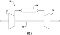
- FIG. 1 illustrates a schematic depiction of an embodiment of a gas turbine 10.
- the gas turbine 10 includes a compressor section 12, a combustion section 14, and a turbine section 16.
- the compressor section 12 and turbine section 16 may be coupled by a shaft 18.
- the shaft 18 may be a single shaft or a plurality of shaft segments coupled together to form the shaft 18.
- the compressor section 12 supplies compressed air to the combustion section 14.
- the compressed air is mixed with fuel and burned within the combustion section 14 to produce hot gases of combustion which flow from the combustion section 14 to the turbine section 16, wherein energy is extracted from the hot gases to produce work.
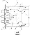
- the combustion section 14 may include a plurality of combustors 20 (one of which is illustrated in FIG. 2 ) positioned in an annular array about a center axis of the gas turbine 10.
- FIG. 2 provides a simplified cross-section of an exemplary combustor 20 known in the art and which may incorporate one or more embodiments of the present disclosure.
- a casing 22 surrounds the combustor 20 to contain compressed air 24 flowing from the compressor section 12 ( FIG. 1 ).
- Multiple fuel nozzles are arranged across an end cover 26.
- a plurality of primary fuel nozzles 28 is circumferentially spaced radially outwardly from a secondary fuel nozzle 30.
- a liner 32 extends downstream from the fuel nozzles 28, 30 and defines an upstream or forward combustion chamber 34 and a downstream or aft combustion chamber 36 which are separated by a throat or converging/diverging portion 38 of the liner 32.
- the primary fuel nozzles 28 may provide fuel to the upstream combustion chamber 34.
- the fuel from the primary fuel nozzles 28 may be burned in the upstream combustion chamber 34 or may be premixed with the compressed air 24 within the upstream combustion chamber 34 for ignition in the downstream combustion chamber 36.
- the secondary fuel nozzle 30 serves several functions in the combustor 20 including supplying a fuel and air mixture to the downstream combustion chamber 36 for premixed mode operation, supplying fuel and air for a pilot flame which supports primary nozzle operation and providing transfer fuel for utilization during changes between operation modes.
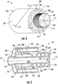
- FIG. 3 provides a cross sectional side view of an exemplary fuel nozzle or fuel nozzle assembly 100 as may be used for the secondary fuel nozzle 30 as shown in FIG. 2 , according to at least one embodiment of the present disclosure.
- the fuel nozzle 100 may be connected to the end cover 26 or may be breach loaded through the end cover 26.
- the fuel nozzle 100 includes an outer tube 102 having an upstream end 104 that is axially spaced from a downstream end 106 with respect to an axial centerline of the fuel nozzle 100.
- An inner tube 108 extends axially within the outer tube 102 and may be coaxially aligned with the outer tube 102.
- the inner tube 108 is radially spaced from the outer tube 102 so as to define an annular air passage 110 therebetween.
- the annular air passage 110 may be in fluid communication with a compressed air source or air circuit defined within the end cover 26.
- the inner tube 108 defines a pilot fuel passage 112 within the outer tube 102.
- the inner tube 108 may be fluidly coupled to an external fuel supply (not shown).
- the fuel nozzle 100 may include an intermediate tube 116 that extends axially within the outer tube 102 with respect to the axial centerline of the fuel nozzle 100.
- the intermediate tube 116 circumferentially surrounds at least a portion of the inner tube 108 and defines a secondary fuel passage 118 within the outer tube 102.
- a plurality of fuel pegs 120 may be circumferentially spaced about the outer tube 102. Each fuel peg 120 extends radially outwardly from the outer tube 102 with respect to the axial centerline of the fuel nozzle 100.
- One or more of the fuel pegs 120 may include one or more fuel injection orifices 122 which are in fluid communication with the secondary fuel passage 118.
- the premix pilot nozzle 114 includes a nozzle body 124.
- FIG. 4 provides a perspective view of the premix pilot nozzle 114 according to at least one embodiment of the present disclosure.
- FIG. 5 provides a perspective cross sectional view of the premix pilot nozzle 114 as shown in FIG. 3 .
- the nozzle body 124 includes a forward wall 126 that is axially spaced from an aft wall 128 with respect to an axial centerline of the nozzle body 124 and an outer band 130 that extends axially between the forward wall 126 and the aft wall 128.
- the outer band 130 defines a radially outer perimeter of the nozzle body 124. As shown in FIG. 3 , the outer band 130 may be coupled or connected to the downstream end 106 of the outer tube 102.
- the nozzle body 124 further includes a tip portion 132.
- the tip portion 132 extends axially downstream from the aft wall 128 with respect to an axial centerline of the nozzle body 124 and includes a downstream wall 134.
- the tip portion 132 of the nozzle body 124 may be cylindrical but is not limited to any particular shape unless otherwise recited in the claims.
- the nozzle body 124 further defines or includes a fuel tube or inner wall 136 that extends coaxially within the nozzle body 124 with respect to the axial centerline of the nozzle body 124.
- the fuel tube 136 defines a fuel inlet plenum 138 within the nozzle body 124.
- the fuel inlet plenum 138 extends coaxially within the nozzle body 124 and is partially defined by an inner surface or wall 140 of the downstream wall 134 of the tip portion 132.
- the fuel tube 136 is connected to the inner tube 108 such that the fuel inlet plenum 138 is in fluid communication with the pilot fuel passage 112 of the inner tube 108.
- the nozzle body 124 further includes a fuel distribution plenum or void 142 which is defined inside or within the nozzle body 124.
- the fuel distribution plenum 142 is defined radially outwardly from the fuel tube 136 and as such from the fuel inlet plenum 138 and is separated from the fuel inlet plenum 138 via the fuel tube 136.
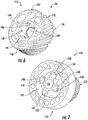
- FIG. 6 provides a cross sectioned perspective view of a portion of the tip portion 132 of the premix pilot nozzle 114 as taken along section lines A-A as shown in FIG. 3 .
- FIG. 7 provides a cross sectioned perspective view of a portion of the premix pilot nozzle 114 as taken along section lines B-B as shown in FIG. 3 .
- FIG. 8 provides a cross sectioned perspective view of a portion of the premix pilot nozzle 114 as taken along section lines C-C as shown in FIG. 3 .
- the fuel inlet plenum 138 is in fluid communication with the fuel distribution plenum 142 via a plurality of orifices or openings 144 which are circumferentially spaced about the axial centerline of the nozzle body 124 with respect to the axial centerline of the nozzle body 124.
- the orifices 144 are defined proximate to or adjacent to the inner surface 140 of the downstream wall 134.
- the inner surface 140 of the downstream wall 134 includes a plurality of heat transfer features 146 which protrude outwardly from the inner surface 140 of the downstream wall 134 within the fuel inlet plenum 138.
- the heat transfer features 146 comprise a plurality of pins or pin fins. At least some of the heat transfer features 146 may be positioned within or proximate to the orifices 144.
- the nozzle body 124 includes a plurality of premix tubes 148 disposed radially outwardly from the fuel tube 136 and/or from the fuel inlet plenum 138.
- Each premix tube 148 defines a respective premix passage 150 through the nozzle body 124.
- the plurality of premix tubes 148 and as such to the respective premix passages 150 extend helically around the fuel tube 136 and/or the fuel inlet plenum 138 within the fuel distribution plenum 142 with respect to the axial centerline of the nozzle body 124.
- each premix tube 148 and as such each premix passage 150 includes a respective inlet 152 ( FIG. 5 ) defined along the forward wall 126 and a respective outlet 154 ( FIG. 4 ) defined along the downstream wall 134 of the tip portion 132.
- the respective inlets 152 are circumferentially spaced along the forward wall 126 and annularly arranged about the axial centerline of the nozzle body 124.
- the respective outlets 154 are circumferentially spaced along the downstream wall 134 and annularly arranged about the axial centerline of the nozzle body 124.
- each premix tube 148 and as such each premix passage 150 may be in fluid communication with the fuel distribution plenum 142 via one or more fuel ports 156 defined along each respective premix tube 148.
- the fuel nozzle assembly 100 includes a plurality of air passages 158 annularly arranged around and disposed radially outwardly from the plurality of premix tubes 148 and as such annularly arranged the premix passages 150 with respect to the axial centerline of the nozzle body 124.
- the plurality of air passages 158 may be defined by the nozzle body 124 and/or may be part of the premix pilot nozzle 114.
- Each air passage 158 of the plurality of air passages 158 comprises a respective inlet 160 which is defined along the forward wall 126 and respective outlet 162 which is defined along the aft wall 128 of the nozzle body 124.
- a portion of the downstream wall 134 of the tip portion 132 which is defined radially inwardly from the respective outlets 154 of the premix passages 150 is dimpled or concaved inwardly along the axial centerline of the nozzle body 124 towards the forward wall 126.
- a radially outer surface 164 of the tip portion 132 of the nozzle body 124 includes a plurality of grooves 166 that extend helically along the outer surface 164 about the axial centerline of the nozzle body 124 between the aft wall 128 and the downstream wall 134 of the nozzle body 124.
- the nozzle body 124 is formed as a singular body.
- the forward wall 126, the aft wall 128, the outer band 130, the tip portion 132, the fuel tube 136, the premix tubes 148 and the air passages 158 may all be formed as a singular body.
- the nozzle body 124 is formed via an additive manufacturing process.
- additive manufacturing or additively manufactured as used herein refers to any process which results in a useful, three-dimensional object and includes a step of sequentially forming the shape of the object one layer at a time.
- Additive manufacturing processes may include three-dimensional printing (3DP) processes, laser-net-shape manufacturing, direct metal laser sintering (DMLS), direct metal laser melting (DMLM), plasma transferred arc, freeform fabrication, etc.
- the premix pilot nozzle 114 air flows from the annular air passage 110 defined between the inner tube 108 and the outer tube 102 and through the plurality of air passages 158 and through the respective premix passages 150.
- Fuel flows through the pilot fuel passage 112 and into the fuel inlet plenum 138 via the inner tube 108 and the fuel tube 136.
- the fuel flows across the inner surface 140 of the downstream wall 134 and into the fuel distribution plenum 142 via the plurality of orifices 144.
- the relatively cool fuel provides cooling to the downstream wall 134, thereby enhancing the mechanical life of the premix pilot nozzle 114.
- the heat transfer features 146 such as the pins, provide for enhanced heat transfer between the downstream wall 134 and the fuel.
- the dimpled portion of the downstream wall 134 may also serve to reduce the operating temperature of the downstream wall 134.
- the fuel then flows from the fuel distribution plenum 142 and into the respective premix passages 150 via the respective fuel ports 156.
- the fuel and air mix within the respective premix passages 150 before being injected into the downstream combustion chamber 36 for combustion.
- the premix pilot nozzle 114 as shown and described herein, may replace known high temperature and high Emissions diffusion type pilot nozzles which stabilize the flame in the downstream combustion chamber 36 at high temperature but at the expense of emissions.
- the premix pilot nozzle 114 as shown and described herein may replace known diffusion type premix pilot nozzles with a swirl stabilized premixed pilot nozzle.
- the premixed pilot nozzle 114 may result in more desirable emissions levels with the same flame stability provided by known diffusion type pilot nozzles while also providing improved dynamics and/or lean blow out limits.
Landscapes
- Engineering & Computer Science (AREA)
- Chemical & Material Sciences (AREA)
- Combustion & Propulsion (AREA)
- Mechanical Engineering (AREA)
- General Engineering & Computer Science (AREA)
- Spray-Type Burners (AREA)
Applications Claiming Priority (1)
| Application Number | Priority Date | Filing Date | Title |
|---|---|---|---|
| US15/188,163 US10443854B2 (en) | 2016-06-21 | 2016-06-21 | Pilot premix nozzle and fuel nozzle assembly |
Publications (3)
| Publication Number | Publication Date |
|---|---|
| EP3282191A2 true EP3282191A2 (de) | 2018-02-14 |
| EP3282191A3 EP3282191A3 (de) | 2018-04-18 |
| EP3282191B1 EP3282191B1 (de) | 2019-05-22 |
Family
ID=59091421
Family Applications (1)
| Application Number | Title | Priority Date | Filing Date |
|---|---|---|---|
| EP17176815.3A Active EP3282191B1 (de) | 2016-06-21 | 2017-06-20 | Pilotvormischungsdüse und brennstoffdüsenanordnung |
Country Status (4)
| Country | Link |
|---|---|
| US (1) | US10443854B2 (de) |
| EP (1) | EP3282191B1 (de) |
| JP (1) | JP7098283B2 (de) |
| CN (1) | CN206973615U (de) |
Families Citing this family (12)
| Publication number | Priority date | Publication date | Assignee | Title |
|---|---|---|---|---|
| US10690350B2 (en) * | 2016-11-28 | 2020-06-23 | General Electric Company | Combustor with axially staged fuel injection |
| US11156362B2 (en) | 2016-11-28 | 2021-10-26 | General Electric Company | Combustor with axially staged fuel injection |
| JP7165545B2 (ja) * | 2018-09-25 | 2022-11-04 | 三菱重工業株式会社 | ガスタービン用燃焼器 |
| KR102312716B1 (ko) * | 2020-06-22 | 2021-10-13 | 두산중공업 주식회사 | 연료 분사 장치, 노즐, 연소기, 및 이를 포함하는 가스 터빈 |
| EP4165348B1 (de) * | 2020-07-17 | 2024-04-17 | Siemens Energy Global GmbH & Co. KG | Vormischinjektoranordnung in einem gasturbinenmotor |
| US11614233B2 (en) | 2020-08-31 | 2023-03-28 | General Electric Company | Impingement panel support structure and method of manufacture |
| US11460191B2 (en) | 2020-08-31 | 2022-10-04 | General Electric Company | Cooling insert for a turbomachine |
| US11371702B2 (en) | 2020-08-31 | 2022-06-28 | General Electric Company | Impingement panel for a turbomachine |
| US11255545B1 (en) | 2020-10-26 | 2022-02-22 | General Electric Company | Integrated combustion nozzle having a unified head end |
| US11506388B1 (en) * | 2021-05-07 | 2022-11-22 | General Electric Company | Furcating pilot pre-mixer for main mini-mixer array in a gas turbine engine |
| US11774099B2 (en) | 2021-06-30 | 2023-10-03 | General Electric Company | Gas turbine fuel nozzle tip comprising an impingement wall |
| US11767766B1 (en) | 2022-07-29 | 2023-09-26 | General Electric Company | Turbomachine airfoil having impingement cooling passages |
Family Cites Families (28)
| Publication number | Priority date | Publication date | Assignee | Title |
|---|---|---|---|---|
| US6446439B1 (en) | 1999-11-19 | 2002-09-10 | Power Systems Mfg., Llc | Pre-mix nozzle and full ring fuel distribution system for a gas turbine combustor |
| US7104067B2 (en) * | 2002-10-24 | 2006-09-12 | General Electric Company | Combustor liner with inverted turbulators |
| US7024861B2 (en) | 2002-12-20 | 2006-04-11 | Martling Vincent C | Fully premixed pilotless secondary fuel nozzle with improved tip cooling |
| US6813890B2 (en) | 2002-12-20 | 2004-11-09 | Power Systems Mfg. Llc. | Fully premixed pilotless secondary fuel nozzle |
| FR2875584B1 (fr) | 2004-09-23 | 2009-10-30 | Snecma Moteurs Sa | Injecteur a effervescence pour systeme aeromecanique d'injection air/carburant dans une chambre de combustion de turbomachine |
| CA2630721C (en) | 2005-12-14 | 2012-06-19 | Rolls-Royce Power Engineering Plc | Gas turbine engine premix injectors |
| US7762070B2 (en) * | 2006-05-11 | 2010-07-27 | Siemens Energy, Inc. | Pilot nozzle heat shield having internal turbulators |
| US7748221B2 (en) * | 2006-11-17 | 2010-07-06 | Pratt & Whitney Canada Corp. | Combustor heat shield with variable cooling |
| US7908863B2 (en) | 2008-02-12 | 2011-03-22 | General Electric Company | Fuel nozzle for a gas turbine engine and method for fabricating the same |
| US8281595B2 (en) | 2008-05-28 | 2012-10-09 | General Electric Company | Fuse for flame holding abatement in premixer of combustion chamber of gas turbine and associated method |
| US8312722B2 (en) * | 2008-10-23 | 2012-11-20 | General Electric Company | Flame holding tolerant fuel and air premixer for a gas turbine combustor |
| US8468831B2 (en) | 2009-07-13 | 2013-06-25 | General Electric Company | Lean direct injection for premixed pilot application |
| US8181891B2 (en) | 2009-09-08 | 2012-05-22 | General Electric Company | Monolithic fuel injector and related manufacturing method |
| US8677760B2 (en) | 2010-01-06 | 2014-03-25 | General Electric Company | Fuel nozzle with integrated passages and method of operation |
| US8919673B2 (en) | 2010-04-14 | 2014-12-30 | General Electric Company | Apparatus and method for a fuel nozzle |
| US8464537B2 (en) | 2010-10-21 | 2013-06-18 | General Electric Company | Fuel nozzle for combustor |
| US20130219899A1 (en) | 2012-02-27 | 2013-08-29 | General Electric Company | Annular premixed pilot in fuel nozzle |
| US8925323B2 (en) * | 2012-04-30 | 2015-01-06 | General Electric Company | Fuel/air premixing system for turbine engine |
| US9562692B2 (en) | 2013-02-06 | 2017-02-07 | Siemens Aktiengesellschaft | Nozzle with multi-tube fuel passageway for gas turbine engines |
| US9297535B2 (en) | 2013-02-25 | 2016-03-29 | General Electric Company | Fuel/air mixing system for fuel nozzle |
| US9217373B2 (en) | 2013-02-27 | 2015-12-22 | General Electric Company | Fuel nozzle for reducing modal coupling of combustion dynamics |
| US9435540B2 (en) | 2013-12-11 | 2016-09-06 | General Electric Company | Fuel injector with premix pilot nozzle |
| US9625146B2 (en) * | 2014-07-11 | 2017-04-18 | Delavan Inc. | Swirl slot relief in a liquid swirler |
| US11015809B2 (en) * | 2014-12-30 | 2021-05-25 | General Electric Company | Pilot nozzle in gas turbine combustor |
| CN204665353U (zh) | 2015-02-26 | 2015-09-23 | 北京华清燃气轮机与煤气化联合循环工程技术有限公司 | 一种用于燃气轮机燃烧室的防回火喷嘴 |
| US9803867B2 (en) | 2015-04-21 | 2017-10-31 | General Electric Company | Premix pilot nozzle |
| US20170089581A1 (en) * | 2015-09-28 | 2017-03-30 | Pratt & Whitney Canada Corp. | Single skin combustor heat transfer augmenters |
| US10738707B2 (en) * | 2015-11-09 | 2020-08-11 | General Electric Company | Igniter for a gas turbine engine |
-
2016
- 2016-06-21 US US15/188,163 patent/US10443854B2/en active Active
-
2017
- 2017-06-12 JP JP2017114812A patent/JP7098283B2/ja active Active
- 2017-06-20 EP EP17176815.3A patent/EP3282191B1/de active Active
- 2017-06-21 CN CN201720745638.7U patent/CN206973615U/zh active Active
Non-Patent Citations (1)
| Title |
|---|
| None |
Also Published As
| Publication number | Publication date |
|---|---|
| EP3282191A3 (de) | 2018-04-18 |
| JP2017227431A (ja) | 2017-12-28 |
| JP7098283B2 (ja) | 2022-07-11 |
| US10443854B2 (en) | 2019-10-15 |
| US20170363293A1 (en) | 2017-12-21 |
| CN206973615U (zh) | 2018-02-06 |
| EP3282191B1 (de) | 2019-05-22 |
Similar Documents
| Publication | Publication Date | Title |
|---|---|---|
| EP3282191B1 (de) | Pilotvormischungsdüse und brennstoffdüsenanordnung | |
| US20220186930A1 (en) | Fuel nozzle structure for air assist injection | |
| US8919673B2 (en) | Apparatus and method for a fuel nozzle | |
| US8756934B2 (en) | Combustor cap assembly | |
| US7757491B2 (en) | Fuel nozzle for a gas turbine engine and method for fabricating the same | |
| US20170363294A1 (en) | Pilot premix nozzle and fuel nozzle assembly | |
| US9714767B2 (en) | Premix fuel nozzle assembly | |
| CN106969379B (zh) | 预混燃料喷嘴组件筒 | |
| CN106066048B (zh) | 预混引导喷嘴 | |
| US8550809B2 (en) | Combustor and method for conditioning flow through a combustor | |
| US10228140B2 (en) | Gas-only cartridge for a premix fuel nozzle | |
| EP2788685B1 (de) | Mehrzonige brennkammer | |
| EP3376109B1 (de) | Zweistoffbrennstoffdüse mit flüssigbrennstoffspitze | |
| KR101774094B1 (ko) | 가스 터빈 엔진에서 사용되는 예비혼합형 접선방향 연료-공기 노즐을 가진 캔-애뉼러형 연소실 | |
| US10030869B2 (en) | Premix fuel nozzle assembly | |
| US11566790B1 (en) | Methods of operating a turbomachine combustor on hydrogen | |
| WO2015069131A1 (en) | Liquid fuel cartridge for a fuel nozzle | |
| US20180340689A1 (en) | Low Profile Axially Staged Fuel Injector | |
| US10724741B2 (en) | Combustors and methods of assembling the same |
Legal Events
| Date | Code | Title | Description |
|---|---|---|---|
| PUAI | Public reference made under article 153(3) epc to a published international application that has entered the european phase |
Free format text: ORIGINAL CODE: 0009012 |
|
| STAA | Information on the status of an ep patent application or granted ep patent |
Free format text: STATUS: THE APPLICATION HAS BEEN PUBLISHED |
|
| AK | Designated contracting states |
Kind code of ref document: A2 Designated state(s): AL AT BE BG CH CY CZ DE DK EE ES FI FR GB GR HR HU IE IS IT LI LT LU LV MC MK MT NL NO PL PT RO RS SE SI SK SM TR |
|
| AX | Request for extension of the european patent |
Extension state: BA ME |
|
| PUAL | Search report despatched |
Free format text: ORIGINAL CODE: 0009013 |
|
| AK | Designated contracting states |
Kind code of ref document: A3 Designated state(s): AL AT BE BG CH CY CZ DE DK EE ES FI FR GB GR HR HU IE IS IT LI LT LU LV MC MK MT NL NO PL PT RO RS SE SI SK SM TR |
|
| AX | Request for extension of the european patent |
Extension state: BA ME |
|
| RIC1 | Information provided on ipc code assigned before grant |
Ipc: F23R 3/34 20060101ALI20180312BHEP Ipc: F23R 3/28 20060101AFI20180312BHEP |
|
| STAA | Information on the status of an ep patent application or granted ep patent |
Free format text: STATUS: REQUEST FOR EXAMINATION WAS MADE |
|
| 17P | Request for examination filed |
Effective date: 20181018 |
|
| RBV | Designated contracting states (corrected) |
Designated state(s): AL AT BE BG CH CY CZ DE DK EE ES FI FR GB GR HR HU IE IS IT LI LT LU LV MC MK MT NL NO PL PT RO RS SE SI SK SM TR |
|
| GRAP | Despatch of communication of intention to grant a patent |
Free format text: ORIGINAL CODE: EPIDOSNIGR1 |
|
| STAA | Information on the status of an ep patent application or granted ep patent |
Free format text: STATUS: GRANT OF PATENT IS INTENDED |
|
| INTG | Intention to grant announced |
Effective date: 20181221 |
|
| GRAS | Grant fee paid |
Free format text: ORIGINAL CODE: EPIDOSNIGR3 |
|
| GRAA | (expected) grant |
Free format text: ORIGINAL CODE: 0009210 |
|
| STAA | Information on the status of an ep patent application or granted ep patent |
Free format text: STATUS: THE PATENT HAS BEEN GRANTED |
|
| AK | Designated contracting states |
Kind code of ref document: B1 Designated state(s): AL AT BE BG CH CY CZ DE DK EE ES FI FR GB GR HR HU IE IS IT LI LT LU LV MC MK MT NL NO PL PT RO RS SE SI SK SM TR |
|
| REG | Reference to a national code |
Ref country code: GB Ref legal event code: FG4D |
|
| REG | Reference to a national code |
Ref country code: CH Ref legal event code: EP |
|
| REG | Reference to a national code |
Ref country code: IE Ref legal event code: FG4D |
|
| REG | Reference to a national code |
Ref country code: DE Ref legal event code: R096 Ref document number: 602017004070 Country of ref document: DE |
|
| REG | Reference to a national code |
Ref country code: AT Ref legal event code: REF Ref document number: 1136571 Country of ref document: AT Kind code of ref document: T Effective date: 20190615 |
|
| REG | Reference to a national code |
Ref country code: NL Ref legal event code: MP Effective date: 20190522 |
|
| REG | Reference to a national code |
Ref country code: LT Ref legal event code: MG4D |
|
| PG25 | Lapsed in a contracting state [announced via postgrant information from national office to epo] |
Ref country code: SE Free format text: LAPSE BECAUSE OF FAILURE TO SUBMIT A TRANSLATION OF THE DESCRIPTION OR TO PAY THE FEE WITHIN THE PRESCRIBED TIME-LIMIT Effective date: 20190522 Ref country code: NL Free format text: LAPSE BECAUSE OF FAILURE TO SUBMIT A TRANSLATION OF THE DESCRIPTION OR TO PAY THE FEE WITHIN THE PRESCRIBED TIME-LIMIT Effective date: 20190522 Ref country code: AL Free format text: LAPSE BECAUSE OF FAILURE TO SUBMIT A TRANSLATION OF THE DESCRIPTION OR TO PAY THE FEE WITHIN THE PRESCRIBED TIME-LIMIT Effective date: 20190522 Ref country code: PT Free format text: LAPSE BECAUSE OF FAILURE TO SUBMIT A TRANSLATION OF THE DESCRIPTION OR TO PAY THE FEE WITHIN THE PRESCRIBED TIME-LIMIT Effective date: 20190922 Ref country code: FI Free format text: LAPSE BECAUSE OF FAILURE TO SUBMIT A TRANSLATION OF THE DESCRIPTION OR TO PAY THE FEE WITHIN THE PRESCRIBED TIME-LIMIT Effective date: 20190522 Ref country code: NO Free format text: LAPSE BECAUSE OF FAILURE TO SUBMIT A TRANSLATION OF THE DESCRIPTION OR TO PAY THE FEE WITHIN THE PRESCRIBED TIME-LIMIT Effective date: 20190822 Ref country code: LT Free format text: LAPSE BECAUSE OF FAILURE TO SUBMIT A TRANSLATION OF THE DESCRIPTION OR TO PAY THE FEE WITHIN THE PRESCRIBED TIME-LIMIT Effective date: 20190522 Ref country code: HR Free format text: LAPSE BECAUSE OF FAILURE TO SUBMIT A TRANSLATION OF THE DESCRIPTION OR TO PAY THE FEE WITHIN THE PRESCRIBED TIME-LIMIT Effective date: 20190522 Ref country code: ES Free format text: LAPSE BECAUSE OF FAILURE TO SUBMIT A TRANSLATION OF THE DESCRIPTION OR TO PAY THE FEE WITHIN THE PRESCRIBED TIME-LIMIT Effective date: 20190522 |
|
| PG25 | Lapsed in a contracting state [announced via postgrant information from national office to epo] |
Ref country code: GR Free format text: LAPSE BECAUSE OF FAILURE TO SUBMIT A TRANSLATION OF THE DESCRIPTION OR TO PAY THE FEE WITHIN THE PRESCRIBED TIME-LIMIT Effective date: 20190823 Ref country code: BG Free format text: LAPSE BECAUSE OF FAILURE TO SUBMIT A TRANSLATION OF THE DESCRIPTION OR TO PAY THE FEE WITHIN THE PRESCRIBED TIME-LIMIT Effective date: 20190822 Ref country code: RS Free format text: LAPSE BECAUSE OF FAILURE TO SUBMIT A TRANSLATION OF THE DESCRIPTION OR TO PAY THE FEE WITHIN THE PRESCRIBED TIME-LIMIT Effective date: 20190522 Ref country code: LV Free format text: LAPSE BECAUSE OF FAILURE TO SUBMIT A TRANSLATION OF THE DESCRIPTION OR TO PAY THE FEE WITHIN THE PRESCRIBED TIME-LIMIT Effective date: 20190522 |
|
| REG | Reference to a national code |
Ref country code: AT Ref legal event code: MK05 Ref document number: 1136571 Country of ref document: AT Kind code of ref document: T Effective date: 20190522 |
|
| PG25 | Lapsed in a contracting state [announced via postgrant information from national office to epo] |
Ref country code: DK Free format text: LAPSE BECAUSE OF FAILURE TO SUBMIT A TRANSLATION OF THE DESCRIPTION OR TO PAY THE FEE WITHIN THE PRESCRIBED TIME-LIMIT Effective date: 20190522 Ref country code: AT Free format text: LAPSE BECAUSE OF FAILURE TO SUBMIT A TRANSLATION OF THE DESCRIPTION OR TO PAY THE FEE WITHIN THE PRESCRIBED TIME-LIMIT Effective date: 20190522 Ref country code: EE Free format text: LAPSE BECAUSE OF FAILURE TO SUBMIT A TRANSLATION OF THE DESCRIPTION OR TO PAY THE FEE WITHIN THE PRESCRIBED TIME-LIMIT Effective date: 20190522 Ref country code: CZ Free format text: LAPSE BECAUSE OF FAILURE TO SUBMIT A TRANSLATION OF THE DESCRIPTION OR TO PAY THE FEE WITHIN THE PRESCRIBED TIME-LIMIT Effective date: 20190522 Ref country code: RO Free format text: LAPSE BECAUSE OF FAILURE TO SUBMIT A TRANSLATION OF THE DESCRIPTION OR TO PAY THE FEE WITHIN THE PRESCRIBED TIME-LIMIT Effective date: 20190522 Ref country code: SK Free format text: LAPSE BECAUSE OF FAILURE TO SUBMIT A TRANSLATION OF THE DESCRIPTION OR TO PAY THE FEE WITHIN THE PRESCRIBED TIME-LIMIT Effective date: 20190522 |
|
| REG | Reference to a national code |
Ref country code: DE Ref legal event code: R097 Ref document number: 602017004070 Country of ref document: DE |
|
| PG25 | Lapsed in a contracting state [announced via postgrant information from national office to epo] |
Ref country code: MC Free format text: LAPSE BECAUSE OF FAILURE TO SUBMIT A TRANSLATION OF THE DESCRIPTION OR TO PAY THE FEE WITHIN THE PRESCRIBED TIME-LIMIT Effective date: 20190522 Ref country code: SM Free format text: LAPSE BECAUSE OF FAILURE TO SUBMIT A TRANSLATION OF THE DESCRIPTION OR TO PAY THE FEE WITHIN THE PRESCRIBED TIME-LIMIT Effective date: 20190522 Ref country code: IT Free format text: LAPSE BECAUSE OF FAILURE TO SUBMIT A TRANSLATION OF THE DESCRIPTION OR TO PAY THE FEE WITHIN THE PRESCRIBED TIME-LIMIT Effective date: 20190522 |
|
| PLBE | No opposition filed within time limit |
Free format text: ORIGINAL CODE: 0009261 |
|
| REG | Reference to a national code |
Ref country code: BE Ref legal event code: MM Effective date: 20190630 |
|
| STAA | Information on the status of an ep patent application or granted ep patent |
Free format text: STATUS: NO OPPOSITION FILED WITHIN TIME LIMIT |
|
| PG25 | Lapsed in a contracting state [announced via postgrant information from national office to epo] |
Ref country code: TR Free format text: LAPSE BECAUSE OF FAILURE TO SUBMIT A TRANSLATION OF THE DESCRIPTION OR TO PAY THE FEE WITHIN THE PRESCRIBED TIME-LIMIT Effective date: 20190522 |
|
| 26N | No opposition filed |
Effective date: 20200225 |
|
| PG25 | Lapsed in a contracting state [announced via postgrant information from national office to epo] |
Ref country code: IE Free format text: LAPSE BECAUSE OF NON-PAYMENT OF DUE FEES Effective date: 20190620 Ref country code: PL Free format text: LAPSE BECAUSE OF FAILURE TO SUBMIT A TRANSLATION OF THE DESCRIPTION OR TO PAY THE FEE WITHIN THE PRESCRIBED TIME-LIMIT Effective date: 20190522 |
|
| PG25 | Lapsed in a contracting state [announced via postgrant information from national office to epo] |
Ref country code: BE Free format text: LAPSE BECAUSE OF NON-PAYMENT OF DUE FEES Effective date: 20190630 Ref country code: LU Free format text: LAPSE BECAUSE OF NON-PAYMENT OF DUE FEES Effective date: 20190620 Ref country code: SI Free format text: LAPSE BECAUSE OF FAILURE TO SUBMIT A TRANSLATION OF THE DESCRIPTION OR TO PAY THE FEE WITHIN THE PRESCRIBED TIME-LIMIT Effective date: 20190522 |
|
| PG25 | Lapsed in a contracting state [announced via postgrant information from national office to epo] |
Ref country code: FR Free format text: LAPSE BECAUSE OF NON-PAYMENT OF DUE FEES Effective date: 20190722 |
|
| REG | Reference to a national code |
Ref country code: CH Ref legal event code: PL |
|
| PG25 | Lapsed in a contracting state [announced via postgrant information from national office to epo] |
Ref country code: LI Free format text: LAPSE BECAUSE OF NON-PAYMENT OF DUE FEES Effective date: 20200630 Ref country code: CH Free format text: LAPSE BECAUSE OF NON-PAYMENT OF DUE FEES Effective date: 20200630 |
|
| PG25 | Lapsed in a contracting state [announced via postgrant information from national office to epo] |
Ref country code: CY Free format text: LAPSE BECAUSE OF FAILURE TO SUBMIT A TRANSLATION OF THE DESCRIPTION OR TO PAY THE FEE WITHIN THE PRESCRIBED TIME-LIMIT Effective date: 20190522 |
|
| PG25 | Lapsed in a contracting state [announced via postgrant information from national office to epo] |
Ref country code: IS Free format text: LAPSE BECAUSE OF FAILURE TO SUBMIT A TRANSLATION OF THE DESCRIPTION OR TO PAY THE FEE WITHIN THE PRESCRIBED TIME-LIMIT Effective date: 20190922 |
|
| PG25 | Lapsed in a contracting state [announced via postgrant information from national office to epo] |
Ref country code: MT Free format text: LAPSE BECAUSE OF FAILURE TO SUBMIT A TRANSLATION OF THE DESCRIPTION OR TO PAY THE FEE WITHIN THE PRESCRIBED TIME-LIMIT Effective date: 20190522 Ref country code: HU Free format text: LAPSE BECAUSE OF FAILURE TO SUBMIT A TRANSLATION OF THE DESCRIPTION OR TO PAY THE FEE WITHIN THE PRESCRIBED TIME-LIMIT; INVALID AB INITIO Effective date: 20170620 |
|
| GBPC | Gb: european patent ceased through non-payment of renewal fee |
Effective date: 20210620 |
|
| PG25 | Lapsed in a contracting state [announced via postgrant information from national office to epo] |
Ref country code: GB Free format text: LAPSE BECAUSE OF NON-PAYMENT OF DUE FEES Effective date: 20210620 |
|
| PG25 | Lapsed in a contracting state [announced via postgrant information from national office to epo] |
Ref country code: MK Free format text: LAPSE BECAUSE OF FAILURE TO SUBMIT A TRANSLATION OF THE DESCRIPTION OR TO PAY THE FEE WITHIN THE PRESCRIBED TIME-LIMIT Effective date: 20190522 |
|
| P01 | Opt-out of the competence of the unified patent court (upc) registered |
Effective date: 20230522 |
|
| PGFP | Annual fee paid to national office [announced via postgrant information from national office to epo] |
Ref country code: DE Payment date: 20230523 Year of fee payment: 7 |
|
| REG | Reference to a national code |
Ref country code: DE Ref legal event code: R082 Ref document number: 602017004070 Country of ref document: DE Ref country code: DE Ref legal event code: R081 Ref document number: 602017004070 Country of ref document: DE Owner name: GENERAL ELECTRIC TECHNOLOGY GMBH, CH Free format text: FORMER OWNER: GENERAL ELECTRIC COMPANY, SCHENECTADY, NY, US |