EP3282117A1 - Exhaust duct for turbine forward of fan - Google Patents
Exhaust duct for turbine forward of fan Download PDFInfo
- Publication number
- EP3282117A1 EP3282117A1 EP17185189.2A EP17185189A EP3282117A1 EP 3282117 A1 EP3282117 A1 EP 3282117A1 EP 17185189 A EP17185189 A EP 17185189A EP 3282117 A1 EP3282117 A1 EP 3282117A1
- Authority
- EP
- European Patent Office
- Prior art keywords
- outlet
- engine
- section
- propulsor
- aft
- Prior art date
- Legal status (The legal status is an assumption and is not a legal conclusion. Google has not performed a legal analysis and makes no representation as to the accuracy of the status listed.)
- Granted
Links
Images




Classifications
-
- F—MECHANICAL ENGINEERING; LIGHTING; HEATING; WEAPONS; BLASTING
- F02—COMBUSTION ENGINES; HOT-GAS OR COMBUSTION-PRODUCT ENGINE PLANTS
- F02K—JET-PROPULSION PLANTS
- F02K3/00—Plants including a gas turbine driving a compressor or a ducted fan
-
- B—PERFORMING OPERATIONS; TRANSPORTING
- B64—AIRCRAFT; AVIATION; COSMONAUTICS
- B64D—EQUIPMENT FOR FITTING IN OR TO AIRCRAFT; FLIGHT SUITS; PARACHUTES; ARRANGEMENT OR MOUNTING OF POWER PLANTS OR PROPULSION TRANSMISSIONS IN AIRCRAFT
- B64D27/00—Arrangement or mounting of power plants in aircraft; Aircraft characterised by the type or position of power plants
- B64D27/02—Aircraft characterised by the type or position of power plants
- B64D27/10—Aircraft characterised by the type or position of power plants of gas-turbine type
- B64D27/14—Aircraft characterised by the type or position of power plants of gas-turbine type within, or attached to, fuselages
-
- B—PERFORMING OPERATIONS; TRANSPORTING
- B64—AIRCRAFT; AVIATION; COSMONAUTICS
- B64D—EQUIPMENT FOR FITTING IN OR TO AIRCRAFT; FLIGHT SUITS; PARACHUTES; ARRANGEMENT OR MOUNTING OF POWER PLANTS OR PROPULSION TRANSMISSIONS IN AIRCRAFT
- B64D33/00—Arrangement in aircraft of power plant parts or auxiliaries not otherwise provided for
- B64D33/02—Arrangement in aircraft of power plant parts or auxiliaries not otherwise provided for of combustion air intakes
-
- B—PERFORMING OPERATIONS; TRANSPORTING
- B64—AIRCRAFT; AVIATION; COSMONAUTICS
- B64D—EQUIPMENT FOR FITTING IN OR TO AIRCRAFT; FLIGHT SUITS; PARACHUTES; ARRANGEMENT OR MOUNTING OF POWER PLANTS OR PROPULSION TRANSMISSIONS IN AIRCRAFT
- B64D33/00—Arrangement in aircraft of power plant parts or auxiliaries not otherwise provided for
- B64D33/04—Arrangement in aircraft of power plant parts or auxiliaries not otherwise provided for of exhaust outlets or jet pipes
-
- B—PERFORMING OPERATIONS; TRANSPORTING
- B64—AIRCRAFT; AVIATION; COSMONAUTICS
- B64D—EQUIPMENT FOR FITTING IN OR TO AIRCRAFT; FLIGHT SUITS; PARACHUTES; ARRANGEMENT OR MOUNTING OF POWER PLANTS OR PROPULSION TRANSMISSIONS IN AIRCRAFT
- B64D35/00—Transmitting power from power plants to propellers or rotors; Arrangements of transmissions
- B64D35/04—Transmitting power from power plants to propellers or rotors; Arrangements of transmissions characterised by the transmission driving a plurality of propellers or rotors
-
- F—MECHANICAL ENGINEERING; LIGHTING; HEATING; WEAPONS; BLASTING
- F02—COMBUSTION ENGINES; HOT-GAS OR COMBUSTION-PRODUCT ENGINE PLANTS
- F02K—JET-PROPULSION PLANTS
- F02K1/00—Plants characterised by the form or arrangement of the jet pipe or nozzle; Jet pipes or nozzles peculiar thereto
- F02K1/52—Nozzles specially constructed for positioning adjacent to another nozzle or to a fixed member, e.g. fairing
-
- F—MECHANICAL ENGINEERING; LIGHTING; HEATING; WEAPONS; BLASTING
- F02—COMBUSTION ENGINES; HOT-GAS OR COMBUSTION-PRODUCT ENGINE PLANTS
- F02K—JET-PROPULSION PLANTS
- F02K3/00—Plants including a gas turbine driving a compressor or a ducted fan
- F02K3/02—Plants including a gas turbine driving a compressor or a ducted fan in which part of the working fluid by-passes the turbine and combustion chamber
- F02K3/04—Plants including a gas turbine driving a compressor or a ducted fan in which part of the working fluid by-passes the turbine and combustion chamber the plant including ducted fans, i.e. fans with high volume, low pressure outputs, for augmenting the jet thrust, e.g. of double-flow type
- F02K3/062—Plants including a gas turbine driving a compressor or a ducted fan in which part of the working fluid by-passes the turbine and combustion chamber the plant including ducted fans, i.e. fans with high volume, low pressure outputs, for augmenting the jet thrust, e.g. of double-flow type with aft fan
-
- B—PERFORMING OPERATIONS; TRANSPORTING
- B64—AIRCRAFT; AVIATION; COSMONAUTICS
- B64D—EQUIPMENT FOR FITTING IN OR TO AIRCRAFT; FLIGHT SUITS; PARACHUTES; ARRANGEMENT OR MOUNTING OF POWER PLANTS OR PROPULSION TRANSMISSIONS IN AIRCRAFT
- B64D27/00—Arrangement or mounting of power plants in aircraft; Aircraft characterised by the type or position of power plants
- B64D27/02—Aircraft characterised by the type or position of power plants
- B64D27/026—Aircraft characterised by the type or position of power plants comprising different types of power plants, e.g. combination of a piston engine and a gas-turbine
-
- F—MECHANICAL ENGINEERING; LIGHTING; HEATING; WEAPONS; BLASTING
- F05—INDEXING SCHEMES RELATING TO ENGINES OR PUMPS IN VARIOUS SUBCLASSES OF CLASSES F01-F04
- F05D—INDEXING SCHEME FOR ASPECTS RELATING TO NON-POSITIVE-DISPLACEMENT MACHINES OR ENGINES, GAS-TURBINES OR JET-PROPULSION PLANTS
- F05D2250/00—Geometry
- F05D2250/30—Arrangement of components
- F05D2250/31—Arrangement of components according to the direction of their main axis or their axis of rotation
- F05D2250/312—Arrangement of components according to the direction of their main axis or their axis of rotation the axes being parallel to each other
Definitions
- a gas turbine engine typically includes a fan section, a compressor section, a combustor section and a turbine section. Air entering the compressor section is compressed and delivered into the combustion section where it is mixed with fuel and ignited to generate a high-speed exhaust gas flow. The high-energy exhaust gas flow expands through the turbine section to drive the compressor and the fan section.
- a speed reduction device such as an epicyclical gear assembly driven by a core engine enables alternative placement of the gas turbine engine.
- the core components of the gas turbine engine such as the compressor, combustor and turbine can be imbedded within the aircraft body.
- a fan section may then be mounted in alternate locations such as at the rear of the aircraft body. In such a configuration the fan is aft of the core engine components and exhaust gases flow past the fan. It is not desirable to ingest the hot exhaust gases into the fan.
- a gas turbine engine in a featured embodiment, includes a core engine assembly including a compressor section communicating air to a combustor section where the air is mixed with fuel and ignited to generate a high-energy gas flow that is expanded through a turbine section.
- the turbine section is coupled to drive the compressor section.
- a propulsor section aft of the core engine is driven by the turbine section.
- An exhaust duct routing exhaust gases around the propulsor section.
- the exhaust duct includes an inlet forward of the propulsor section, an outlet aft of the turbine section and a passageway between the inlet and the outlet.
- the outlet is aft of the propulsor section.
- the inlet is transverse to an axis of the core engine and open 360 degrees about the axis of the core engine and the outlet defines an opening spaced radially apart from the engine axis.
- the outlet is disposed below the engine axis and includes a width greater than a height.
- the outlet includes a first outlet spaced apart from a second outlet and the passageway includes a first passageway between the inlet and the first outlet and a second passageway between the inlet and the second outlet.
- the first outlet is disposed on one side of the propulsor and the second outlet is disposed on a second side of the propulsor.
- the propulsor includes at least one ducted fan driven by a propulsor shaft driven by the gearbox.
- the core engine section is mounted within an aircraft fuselage and the propulsor section is disposed at an aft section of the aircraft fuselage.
- an aircraft in another featured embodiment, includes a core engine assembly supported within an aircraft fuselage.
- the core engine assembly includes a compressor section communicating air to a combustor section where the air is mixed with fuel and ignited to generate a high-energy gas flow that is expanded through a turbine section.
- An air intake within the aircraft fuselage communicates air to the core engine assembly.
- a propulsor section is aft of the core engine assembly and mounted to an aft section of the aircraft fuselage.
- An exhaust duct routes exhaust gases from the turbine section around the propulsor section and through the aircraft fuselage.
- the exhaust duct includes an inlet opening forward of the propulsor section, an outlet aft of the propulsor section and a passageway between the inlet opening and the outlet.
- the inlet opening is transverse to an axis of the core engine and open 360 degrees about the axis of the core engine and the outlet defines an opening spaced radially apart from the engine axis.
- the outlet includes a first outlet spaced apart from a second outlet and the passageway includes a first passageway between the inlet opening and the first outlet and a second passageway between the inlet opening and the second outlet.
- the first outlet is disposed on one side of the propulsor and the second outlet is disposed on a second side of the propulsor.
- the propulsor includes at least one ducted fan driven by a propulsor shaft driven by the gearbox.
- an exhaust duct routes exhaust from a turbine forward of a fan.
- the exhaust duct includes an inlet opening disposed proximate a turbine outlet.
- the inlet opening is disposed 360 degrees about an engine axis.
- a passageway is spaced apart from the engine axis and extends aft from the inlet opening.
- An outlet opening is disposed aft of a fan such that exhaust flow is routed away from the fan.
- in another embodiment according to the previous embodiment includes a split portion aft of the inlet opening splitting the passageway around the engine axis.
- the outlet includes a rectangular opening aft of the fan and below the engine axis relative to the split portion.
- the outlet includes a first outlet spaced apart from a second outlet and the passageway includes a first passageway between the inlet opening and the first outlet and a second passageway between the inlet opening and the second outlet.
- FIG. 1 schematically illustrates an aircraft 10 that includes an embedded propulsion system 15.
- the example propulsion system 15 includes a core engine 16 also referred to a gas generator that is embedded within the aircraft fuselage 52.
- the core engine 16 drives a propulsor 18 that is disposed at an aft end 54 of the aircraft fuselage 52.
- the example propulsor 18 comprises two fans 36, 38 disposed at the aft end 54.
- the core engine 16 is fed air through an air intake opening 12 and then through an internal inlet 14.
- the intake 12 is disposed forward of the core engine 16 and therefore the inlet 14 communicates the required air through the fuselage 52 to the core engine 16.
- the example core engine 16 includes a compressor section 20 that compresses incoming air and supplies that air to a combustor 22.
- gas is mixed with the air and ignited to generate a high energy exhaust flow that is expanded through a turbine section 24.
- a free or second turbine 26 is disposed aft of the turbine section 24.
- the free or second turbine 26 drives the propulsor 18 through a drive shaft 28.
- the drive shaft 28 along with the compressor 20, combustor 22 and turbine section 24 are disposed along a common engine axis A.
- the propulsor 18 includes ducted fans 36 and 38 that rotate about separate axes B1, B2 that are spaced from the engine axis A. Because the fans 36, 38 are disposed aft of the core engine 16, the drive shaft 28 need not extended through the core engine 16. Accordingly, because the drive shaft 28 is not extending through the central portion of the engine, the entire core engine 16 may be reduced in size. The reduced size enables improved efficiencies.
- the propulsor section 18 includes the first fan 36 and the second fan 38 driven by corresponding shafts 32 and 34 that are in turn driven by a gearbox 30.
- the drive shaft 28 driven by the free turbine 26 drives the gearbox 30.
- the fans 36 and 38 are therefore aft of the core engine 16 and thereby potentially exposed to exhaust gasses expelled from the turbine section 24.
- the example propulsion system 15 includes an exhaust duct 42 that routes harmful exhaust gases around the drive shaft 28, gearbox 30 and the propulsor 18.
- the example exhaust duct 42 includes an exhaust outlet 40 disposed to one side of the propulsor section 18 to prevent incursion into the fans 36, 38.
- the exhaust outlet 40 is disposed below the fans 36 and 38.
- the example exhaust duct 42 is illustrated without the surrounding aircraft fuselage and includes the exhaust outlet 40 that is disposed at the aft portion 54 of the aircraft 10.
- the duct 42 includes a forward intake opening 46.
- the forward intake opening 46 is an annulus disposed about the engine axis A with an outer diameter corresponding to the diameter of the free turbine 26.
- the duct 42 splits the annulus of the intake opening 46 at a split location 44 and wraps outwardly around the drive shaft 28.
- the duct 42 defines enclosed passages that extend around the drive shaft 28 and fan shafts 32 and 34. The duct 42 is therefore spaced away from the engine axis A aft of the split location 44.
- the annulus of the opening 46 is split and wrapped from the split location 44 in a uniform curved duct that extends to the exhaust outlet 40. Accordingly, exhaust gasses are routed from the inlet 46 down to the bottom side of the propulsor 18 such that exhaust exiting the turbine section 24 is routed around and away from the fan ducts 50.
- the example exhaust outlet 40 is substantially rectangular and includes a height 56 substantially less than a width 58. The area provided by the outlet 40 is substantially equal to that of the inlet 46, but shaped differently to direct exhaust gasses around the propulsor 18.
- FIG. 8 another exhaust duct 60 is illustrated that provides for the routing of exhaust gasses from the core engine 16 around the drive shaft 28 and away from the fan ducts 50.
- the exhaust outlet is split into a first outlet 62a and a second outlet 62b that are each disposed on bottom and outward sides of the propulsor section 18.
- the example exhaust duct 60 includes an inlet 66 that is substantially an annulus disposed about the engine axis A like the previous exhaust duct and is split at a split point 68.
- the duct is split into a first leg portion 64a and a second leg portion 64b.
- Each leg portion is a hollow duct that curves around the drive shaft 28 and the propulsor section 18.
- Each of the legs 64a and 64b provide a smooth conduit for exhaust gasses to be communicated to the outlets 62a and 62b on either side of the fans 36, 38 of the propulsor section 18.
- the example exhaust duct configuration enable use of an embedded core engine with a free turbine by routing the exhaust gasses around the output drive shafts and fan ducts.
Landscapes
- Engineering & Computer Science (AREA)
- Mechanical Engineering (AREA)
- Chemical & Material Sciences (AREA)
- Combustion & Propulsion (AREA)
- Aviation & Aerospace Engineering (AREA)
- General Engineering & Computer Science (AREA)
- Laminated Bodies (AREA)
Abstract
Description
- A gas turbine engine typically includes a fan section, a compressor section, a combustor section and a turbine section. Air entering the compressor section is compressed and delivered into the combustion section where it is mixed with fuel and ignited to generate a high-speed exhaust gas flow. The high-energy exhaust gas flow expands through the turbine section to drive the compressor and the fan section.
- A speed reduction device such as an epicyclical gear assembly driven by a core engine enables alternative placement of the gas turbine engine. The core components of the gas turbine engine such as the compressor, combustor and turbine can be imbedded within the aircraft body. A fan section may then be mounted in alternate locations such as at the rear of the aircraft body. In such a configuration the fan is aft of the core engine components and exhaust gases flow past the fan. It is not desirable to ingest the hot exhaust gases into the fan.
- In a featured embodiment, a gas turbine engine includes a core engine assembly including a compressor section communicating air to a combustor section where the air is mixed with fuel and ignited to generate a high-energy gas flow that is expanded through a turbine section. The turbine section is coupled to drive the compressor section. A propulsor section aft of the core engine is driven by the turbine section. An exhaust duct routing exhaust gases around the propulsor section. The exhaust duct includes an inlet forward of the propulsor section, an outlet aft of the turbine section and a passageway between the inlet and the outlet.
- In an embodiment according to the previous embodiment, the outlet is aft of the propulsor section.
- In another embodiment according to any of the previous embodiments, the inlet is transverse to an axis of the core engine and open 360 degrees about the axis of the core engine and the outlet defines an opening spaced radially apart from the engine axis.
- In another embodiment according to any of the previous embodiments, the outlet is disposed below the engine axis and includes a width greater than a height.
- In another embodiment according to any of the previous embodiments, the outlet includes a first outlet spaced apart from a second outlet and the passageway includes a first passageway between the inlet and the first outlet and a second passageway between the inlet and the second outlet.
- In another embodiment according to any of the previous embodiments, the first outlet is disposed on one side of the propulsor and the second outlet is disposed on a second side of the propulsor.
- In another embodiment according to any of the previous embodiments, includes a drive shaft driven by the turbine section of the core engine. The exhaust duct is routed such that exhaust gases are not in communication with the drive shaft.
- In another embodiment according to any of the previous embodiments, includes a free turbine aft of the turbine section. The drive shaft is coupled to the free turbine.
- In another embodiment according to any of the previous embodiments, includes a gearbox driven by the drive shaft. The propulsor includes at least one ducted fan driven by a propulsor shaft driven by the gearbox.
- In another embodiment according to any of the previous embodiments, the core engine section is mounted within an aircraft fuselage and the propulsor section is disposed at an aft section of the aircraft fuselage.
- In another featured embodiment, an aircraft includes a core engine assembly supported within an aircraft fuselage. The core engine assembly includes a compressor section communicating air to a combustor section where the air is mixed with fuel and ignited to generate a high-energy gas flow that is expanded through a turbine section. An air intake within the aircraft fuselage communicates air to the core engine assembly. A propulsor section is aft of the core engine assembly and mounted to an aft section of the aircraft fuselage. An exhaust duct routes exhaust gases from the turbine section around the propulsor section and through the aircraft fuselage. The exhaust duct includes an inlet opening forward of the propulsor section, an outlet aft of the propulsor section and a passageway between the inlet opening and the outlet.
- In an embodiment according to the previous embodiment, the inlet opening is transverse to an axis of the core engine and open 360 degrees about the axis of the core engine and the outlet defines an opening spaced radially apart from the engine axis.
- In another embodiment according to any of the previous embodiments, the outlet includes a first outlet spaced apart from a second outlet and the passageway includes a first passageway between the inlet opening and the first outlet and a second passageway between the inlet opening and the second outlet.
- In another embodiment according to any of the previous embodiments, the first outlet is disposed on one side of the propulsor and the second outlet is disposed on a second side of the propulsor.
- In another embodiment according to any of the previous embodiments, includes a drive shaft driven by the turbine section of the core engine. The exhaust duct is routed such that exhaust gases do not impinge on the drive shaft.
- In another embodiment according to any of the previous embodiments, includes a gearbox driven by the drive shaft. The propulsor includes at least one ducted fan driven by a propulsor shaft driven by the gearbox.
- In another featured embodiment, an exhaust duct routes exhaust from a turbine forward of a fan. The exhaust duct includes an inlet opening disposed proximate a turbine outlet. The inlet opening is disposed 360 degrees about an engine axis. A passageway is spaced apart from the engine axis and extends aft from the inlet opening. An outlet opening is disposed aft of a fan such that exhaust flow is routed away from the fan.
- In another embodiment according to the previous embodiment, includes a split portion aft of the inlet opening splitting the passageway around the engine axis.
- In another embodiment according to any of the previous embodiments, the outlet includes a rectangular opening aft of the fan and below the engine axis relative to the split portion.
- In another embodiment according to any of the previous embodiments, the outlet includes a first outlet spaced apart from a second outlet and the passageway includes a first passageway between the inlet opening and the first outlet and a second passageway between the inlet opening and the second outlet.
- Although the different examples have the specific components shown in the illustrations, embodiments of this disclosure are not limited to those particular combinations. It is possible to use some of the components or features from one of the examples in combination with features or components from another one of the examples.
- These and other features disclosed herein can be best understood from the following specification and drawings, the following of which is a brief description.
-
-
Figure 1 is a schematic view of an example aircraft including a partially embedded propulsion system. -
Figure 2 is an exploded view of the example propulsion system within the aircraft. -
Figure 3 is a schematic illustration of the example propulsion system embedded within the aircraft. -
Figure 4 is a partial cutaway view of the example propulsion system within the aircraft fuselage. -
Figure 5 is a perspective view of an example disclosed exhaust duct. -
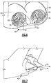
Figure 6 is a rear view of an example exhaust outlet. -
Figure 7 is a side view of the example exhaust outlet. -
Figure 8 is an overhead partial cutaway view of another example exhaust duct. -
Figure 9 is a side view of the example exhaust duct illustrated inFigure 8 . -
Figure 10 is a rear view of the example exhaust duct outlets. -
Figure 11 is a perspective view of another example exhaust duct. -
Figure 1 schematically illustrates anaircraft 10 that includes an embeddedpropulsion system 15. Theexample propulsion system 15 includes acore engine 16 also referred to a gas generator that is embedded within theaircraft fuselage 52. Thecore engine 16 drives apropulsor 18 that is disposed at anaft end 54 of theaircraft fuselage 52. Theexample propulsor 18 comprises twofans aft end 54. Thecore engine 16 is fed air through anair intake opening 12 and then through aninternal inlet 14. Theintake 12 is disposed forward of thecore engine 16 and therefore theinlet 14 communicates the required air through thefuselage 52 to thecore engine 16. - Referring to
Figures 2 and 3 with continued reference toFigure 1 , theexample core engine 16 includes acompressor section 20 that compresses incoming air and supplies that air to acombustor 22. In thecombustor 22, gas is mixed with the air and ignited to generate a high energy exhaust flow that is expanded through aturbine section 24. In the disclosedcore engine 16, a free or second turbine 26 is disposed aft of theturbine section 24. The free or second turbine 26 drives thepropulsor 18 through adrive shaft 28. Thedrive shaft 28 along with thecompressor 20,combustor 22 andturbine section 24 are disposed along a common engine axis A. - The
propulsor 18 includesducted fans fans core engine 16, thedrive shaft 28 need not extended through thecore engine 16. Accordingly, because thedrive shaft 28 is not extending through the central portion of the engine, theentire core engine 16 may be reduced in size. The reduced size enables improved efficiencies. - The
propulsor section 18 includes thefirst fan 36 and thesecond fan 38 driven by correspondingshafts gearbox 30. Thedrive shaft 28 driven by the free turbine 26 drives thegearbox 30. Thefans core engine 16 and thereby potentially exposed to exhaust gasses expelled from theturbine section 24. Theexample propulsion system 15 includes anexhaust duct 42 that routes harmful exhaust gases around thedrive shaft 28,gearbox 30 and thepropulsor 18. - Referring to
Figure 4 with continued reference toFigure 1 , theexample exhaust duct 42 includes anexhaust outlet 40 disposed to one side of thepropulsor section 18 to prevent incursion into thefans exhaust outlet 40 is disposed below thefans - Referring to
Figures 5 ,6 and 7 with continued reference toFigure 4 , theexample exhaust duct 42 is illustrated without the surrounding aircraft fuselage and includes theexhaust outlet 40 that is disposed at theaft portion 54 of theaircraft 10. Theduct 42 includes a forward intake opening 46. The forward intake opening 46 is an annulus disposed about the engine axis A with an outer diameter corresponding to the diameter of the free turbine 26. Theduct 42 splits the annulus of theintake opening 46 at asplit location 44 and wraps outwardly around thedrive shaft 28. Theduct 42 defines enclosed passages that extend around thedrive shaft 28 andfan shafts duct 42 is therefore spaced away from the engine axis A aft of thesplit location 44. - The annulus of the
opening 46 is split and wrapped from thesplit location 44 in a uniform curved duct that extends to theexhaust outlet 40. Accordingly, exhaust gasses are routed from theinlet 46 down to the bottom side of thepropulsor 18 such that exhaust exiting theturbine section 24 is routed around and away from thefan ducts 50. Theexample exhaust outlet 40 is substantially rectangular and includes aheight 56 substantially less than awidth 58. The area provided by theoutlet 40 is substantially equal to that of theinlet 46, but shaped differently to direct exhaust gasses around thepropulsor 18. - Referring to
Figures 8, 9 and 10 , anotherexhaust duct 60 is illustrated that provides for the routing of exhaust gasses from thecore engine 16 around thedrive shaft 28 and away from thefan ducts 50. In this disclosedduct 60, the exhaust outlet is split into a first outlet 62a and a second outlet 62b that are each disposed on bottom and outward sides of thepropulsor section 18. - Referring to
Figure 11 with continued reference toFigures 8, 9 and 10 , theexample exhaust duct 60 includes aninlet 66 that is substantially an annulus disposed about the engine axis A like the previous exhaust duct and is split at asplit point 68. At thesplit point 68 rather than continuing in a single duct, the duct is split into a first leg portion 64a and a second leg portion 64b. Each leg portion is a hollow duct that curves around thedrive shaft 28 and thepropulsor section 18. Each of the legs 64a and 64b provide a smooth conduit for exhaust gasses to be communicated to the outlets 62a and 62b on either side of thefans propulsor section 18. - Accordingly, the example exhaust duct configuration enable use of an embedded core engine with a free turbine by routing the exhaust gasses around the output drive shafts and fan ducts.
- Although an example embodiment has been disclosed, a worker of ordinary skill in this art would recognize that certain modifications would come within the scope of this disclosure. For that reason, the following claims should be studied to determine the scope and content of this disclosure.
Claims (15)
- A gas turbine engine (10) comprising:a core engine (16) including a compressor (20) section communicating air to a combustor section (22) where the air is mixed with fuel and ignited to generate a high-energy gas flow that is expanded through a turbine section (24), wherein the turbine section (24) is coupled to drive the compressor section (20);a propulsor (18) aft of the core engine (16) driven by the turbine section (24); andan exhaust duct (42) routing exhaust gases around the propulsor section (18), the exhaust duct (42) including an inlet (46) forward of the propulsor (18), an outlet (40) aft of the turbine section (24) and a passageway between the inlet (46) and the outlet (40).
- The gas turbine engine (10) as recited in claim 1, wherein the outlet (40) is aft of the propulsor section (18).
- The gas turbine engine (10) as recited in claim 1 or 2, wherein the inlet (46) is transverse to an axis of the core engine (16) and open 360 degrees about the axis of the core engine (16) and the outlet (40) defines an opening spaced radially apart from the engine axis (A).
- The gas turbine engine (10) as recited in claim 3, wherein the outlet (40) is disposed below the engine axis (A) and includes a width (58) greater than a height (56).
- The gas turbine engine (10) as recited in any preceding claim, wherein the outlet (40) comprises a first outlet spaced (62A) apart from a second outlet (62B) and the passageway comprises a first passageway between the inlet (66) and the first outlet (62A) and a second passageway between the inlet (66) and the second outlet (62B).
- The gas turbine engine (10) as recited in claim 5, wherein the first outlet (62A) is disposed on one side of the propulsor (18) and the second outlet (62B) is disposed on a second side of the propulsor (18).
- The gas turbine engine (10) as recited in any preceding claim, including a drive shaft (28) driven by the core engine (16), wherein the exhaust duct (42) is routed such that exhaust gases are not in communication with the drive shaft (28).
- The gas turbine engine (10) as recited in claim 7, including a free turbine (26) aft of the turbine section (24), the drive shaft (28) coupled to the free turbine (26).
- The gas turbine engine (10) as recited in claim 7 or 8, including a gearbox (30) driven by the drive shaft (28), wherein the propulsor (18) includes at least one ducted fan (36, 38) driven by a propulsor shaft (32, 34) driven by the gearbox.
- The gas turbine engine (10) as recited in any preceding claim, wherein the core engine (16) is mounted within an aircraft fuselage (52) and the propulsor (16) is disposed at an aft section of the aircraft fuselage (52).
- An aircraft (10) comprising:the gas turbine engine (10) of claim 10; andan air intake (12) within the aircraft fuselage (52) communicating air to the core engine (16), wherein the exhaust duct (42) routes exhaust gases from the turbine section (24) through the aircraft fuselage (52).
- An exhaust duct (42) for routing exhaust from a turbine (24) forward of a fan (36, 38), the exhaust duct (42) comprising:an inlet opening (46) configured to be disposed proximate a turbine outlet with the inlet opening (46) disposed 360 degrees about an engine axis (A);a passageway configured to be spaced apart from the engine axis (A) and extending aft from the inlet opening (46); andan outlet opening (40) configured to be disposed aft of a fan (36, 38) such that exhaust flow is routed away from the fan (36, 38).
- The exhaust duct (42) as recited in claim 12, including a split portion aft of the inlet opening (46) splitting the passageway around the engine axis (A).
- The exhaust duct (42) as recited in claim 12 or 13, wherein the outlet (40) comprises a rectangular opening configured to be positioned aft of the fan (36, 38) and below the engine axis (A) relative to the split portion.
- The exhaust duct (42) as recited in any of claims 12 to 14, wherein the outlet (40) comprises a first outlet (62A) spaced apart from a second outlet (62B) and the passageway comprises a first passageway (64A) between the inlet opening (66) and the first outlet (62A) and a second passageway (64B) between the inlet opening (66) and the second outlet (62B).
Applications Claiming Priority (1)
| Application Number | Priority Date | Filing Date | Title |
|---|---|---|---|
| US15/230,590 US10267263B2 (en) | 2016-08-08 | 2016-08-08 | Exhaust duct for turbine forward of fan |
Publications (2)
| Publication Number | Publication Date |
|---|---|
| EP3282117A1 true EP3282117A1 (en) | 2018-02-14 |
| EP3282117B1 EP3282117B1 (en) | 2020-10-14 |
Family
ID=59558341
Family Applications (1)
| Application Number | Title | Priority Date | Filing Date |
|---|---|---|---|
| EP17185189.2A Active EP3282117B1 (en) | 2016-08-08 | 2017-08-07 | Exhaust duct for turbine forward of fan |
Country Status (2)
| Country | Link |
|---|---|
| US (1) | US10267263B2 (en) |
| EP (1) | EP3282117B1 (en) |
Cited By (1)
| Publication number | Priority date | Publication date | Assignee | Title |
|---|---|---|---|---|
| EP3617061A1 (en) * | 2018-08-30 | 2020-03-04 | Aurora Flight Sciences Corporation | Mechanically-distributed propulsion drivetrain and architecture |
Families Citing this family (8)
| Publication number | Priority date | Publication date | Assignee | Title |
|---|---|---|---|---|
| FR3045010A1 (en) * | 2015-12-15 | 2017-06-16 | Airbus Operations Sas | MULTI-AXIAL TURBOREACTOR AND REAR AIRCRAFT PART PROVIDED WITH SUCH TURBOJET ENGINES |
| US11111029B2 (en) * | 2017-07-28 | 2021-09-07 | The Boeing Company | System and method for operating a boundary layer ingestion fan |
| US10759545B2 (en) | 2018-06-19 | 2020-09-01 | Raytheon Technologies Corporation | Hybrid electric aircraft system with distributed propulsion |
| US10906657B2 (en) * | 2018-06-19 | 2021-02-02 | Raytheon Technologies Corporation | Aircraft system with distributed propulsion |
| US12187443B2 (en) * | 2020-02-14 | 2025-01-07 | Bombardier Inc. | Excess thrust control for an aircraft |
| US12583609B2 (en) | 2022-12-23 | 2026-03-24 | Pratt & Whitney Canada Corp. | Exhaust duct for hybrid aircraft powerplant |
| US12246844B1 (en) | 2023-11-29 | 2025-03-11 | Pratt & Whitney Canada Corp. | Hybrid aircraft power plant |
| US20250297579A1 (en) * | 2024-03-25 | 2025-09-25 | Rtx Corporation | Open pusher rotor with remote exhaust |
Citations (5)
| Publication number | Priority date | Publication date | Assignee | Title |
|---|---|---|---|---|
| US3054577A (en) * | 1961-02-27 | 1962-09-18 | Forschungszentrums Der Luftfah | Power plant for jet propelled aircraft |
| US20130000273A1 (en) * | 2011-06-29 | 2013-01-03 | United Technologies Corporation | Gas-driven propulsor with tip turbine fan |
| US20130062463A1 (en) * | 2011-09-09 | 2013-03-14 | United Technologies Corporation | Transverse mounted gas turbine engine |
| WO2014109811A2 (en) * | 2012-10-29 | 2014-07-17 | United Technologies Corporation | Twin tip turbine propulsors powered by a single gas turbine generator |
| US20140252161A1 (en) * | 2013-03-11 | 2014-09-11 | United Technologies Corporation | De-couple geared turbo-fan engine and aircraft |
Family Cites Families (5)
| Publication number | Priority date | Publication date | Assignee | Title |
|---|---|---|---|---|
| US6918244B2 (en) | 2001-08-17 | 2005-07-19 | John Eugene Dickau | Vertical takeoff and landing aircraft propulsion systems |
| US6729575B2 (en) | 2002-04-01 | 2004-05-04 | Lockheed Martin Corporation | Propulsion system for a vertical and short takeoff and landing aircraft |
| SE527828C2 (en) | 2004-11-05 | 2006-06-13 | Volvo Aero Corp | Propulsion system for a vehicle |
| US7665689B2 (en) | 2006-11-24 | 2010-02-23 | The Boeing Company | Unconventional integrated propulsion systems and methods for blended wing body aircraft |
| US8317129B1 (en) | 2009-03-25 | 2012-11-27 | The Boeing Company | Universal convergent nozzle and distinct nozzle aperture |
-
2016
- 2016-08-08 US US15/230,590 patent/US10267263B2/en active Active
-
2017
- 2017-08-07 EP EP17185189.2A patent/EP3282117B1/en active Active
Patent Citations (5)
| Publication number | Priority date | Publication date | Assignee | Title |
|---|---|---|---|---|
| US3054577A (en) * | 1961-02-27 | 1962-09-18 | Forschungszentrums Der Luftfah | Power plant for jet propelled aircraft |
| US20130000273A1 (en) * | 2011-06-29 | 2013-01-03 | United Technologies Corporation | Gas-driven propulsor with tip turbine fan |
| US20130062463A1 (en) * | 2011-09-09 | 2013-03-14 | United Technologies Corporation | Transverse mounted gas turbine engine |
| WO2014109811A2 (en) * | 2012-10-29 | 2014-07-17 | United Technologies Corporation | Twin tip turbine propulsors powered by a single gas turbine generator |
| US20140252161A1 (en) * | 2013-03-11 | 2014-09-11 | United Technologies Corporation | De-couple geared turbo-fan engine and aircraft |
Cited By (6)
| Publication number | Priority date | Publication date | Assignee | Title |
|---|---|---|---|---|
| EP3617061A1 (en) * | 2018-08-30 | 2020-03-04 | Aurora Flight Sciences Corporation | Mechanically-distributed propulsion drivetrain and architecture |
| JP2020040649A (en) * | 2018-08-30 | 2020-03-19 | オーロラ フライト サイエンシズ コーポレーション | Mechanically dispersed propulsion drive train and architecture |
| US11142330B2 (en) | 2018-08-30 | 2021-10-12 | Aurora Flight Sciences Corporation | Mechanically-distributed propulsion drivetrain and architecture |
| IL268391B1 (en) * | 2018-08-30 | 2023-03-01 | Aurora Flight Sciences Corp | Mechanically-distributed propulsion drivetrain and architecture |
| IL268391B2 (en) * | 2018-08-30 | 2023-07-01 | Aurora Flight Sciences Corp | Mechanically-distributed propulsion drivetrain and architecture |
| US12110846B2 (en) | 2018-08-30 | 2024-10-08 | Aurora Flight Sciences Corporation, a subsidiary of The Boeing Company | Mechanically-distributed propulsion drivetrain and architecture |
Also Published As
| Publication number | Publication date |
|---|---|
| EP3282117B1 (en) | 2020-10-14 |
| US20180038315A1 (en) | 2018-02-08 |
| US10267263B2 (en) | 2019-04-23 |
Similar Documents
| Publication | Publication Date | Title |
|---|---|---|
| EP3282117A1 (en) | Exhaust duct for turbine forward of fan | |
| US11719247B2 (en) | Reverse flow engine architecture | |
| US20220403774A1 (en) | Gas generator bifurcating exhaust duct to free turbine | |
| US9297270B2 (en) | Gas turbine engine driving multiple fans | |
| US10024235B2 (en) | Offset core engine architecture | |
| EP3284942B1 (en) | Direct drive aft fan engine | |
| CN108930557A (en) | Method and system for compressor vanes leading edge auxiliary vane | |
| US10094281B2 (en) | Gas turbine engine with twin offset gas generators | |
| US10677158B2 (en) | Method and system for in-line distributed propulsion | |
| US10001063B2 (en) | Angled core gas turbine engine mounting | |
| US10502085B2 (en) | Angled reverse core gas turbine engine with widened nozzle | |
| US10428740B2 (en) | Twin shafts driving adjacent fans for aircraft propulsion | |
| US20140053533A1 (en) | Reverse flow gas turbine engine with thrust reverser | |
| US12326112B2 (en) | Gas turbine engine bypass louver and baffle rib design | |
| EP3091183B1 (en) | Thermal regulation channels for turbomachine components | |
| US10174680B2 (en) | Gas turbine engine with distributed fans and bypass air mixer |
Legal Events
| Date | Code | Title | Description |
|---|---|---|---|
| PUAI | Public reference made under article 153(3) epc to a published international application that has entered the european phase |
Free format text: ORIGINAL CODE: 0009012 |
|
| STAA | Information on the status of an ep patent application or granted ep patent |
Free format text: STATUS: THE APPLICATION HAS BEEN PUBLISHED |
|
| AK | Designated contracting states |
Kind code of ref document: A1 Designated state(s): AL AT BE BG CH CY CZ DE DK EE ES FI FR GB GR HR HU IE IS IT LI LT LU LV MC MK MT NL NO PL PT RO RS SE SI SK SM TR |
|
| AX | Request for extension of the european patent |
Extension state: BA ME |
|
| STAA | Information on the status of an ep patent application or granted ep patent |
Free format text: STATUS: REQUEST FOR EXAMINATION WAS MADE |
|
| 17P | Request for examination filed |
Effective date: 20180814 |
|
| RBV | Designated contracting states (corrected) |
Designated state(s): AL AT BE BG CH CY CZ DE DK EE ES FI FR GB GR HR HU IE IS IT LI LT LU LV MC MK MT NL NO PL PT RO RS SE SI SK SM TR |
|
| STAA | Information on the status of an ep patent application or granted ep patent |
Free format text: STATUS: EXAMINATION IS IN PROGRESS |
|
| 17Q | First examination report despatched |
Effective date: 20181210 |
|
| GRAP | Despatch of communication of intention to grant a patent |
Free format text: ORIGINAL CODE: EPIDOSNIGR1 |
|
| STAA | Information on the status of an ep patent application or granted ep patent |
Free format text: STATUS: GRANT OF PATENT IS INTENDED |
|
| INTG | Intention to grant announced |
Effective date: 20200422 |
|
| GRAS | Grant fee paid |
Free format text: ORIGINAL CODE: EPIDOSNIGR3 |
|
| GRAA | (expected) grant |
Free format text: ORIGINAL CODE: 0009210 |
|
| STAA | Information on the status of an ep patent application or granted ep patent |
Free format text: STATUS: THE PATENT HAS BEEN GRANTED |
|
| AK | Designated contracting states |
Kind code of ref document: B1 Designated state(s): AL AT BE BG CH CY CZ DE DK EE ES FI FR GB GR HR HU IE IS IT LI LT LU LV MC MK MT NL NO PL PT RO RS SE SI SK SM TR |
|
| REG | Reference to a national code |
Ref country code: GB Ref legal event code: FG4D |
|
| REG | Reference to a national code |
Ref country code: AT Ref legal event code: REF Ref document number: 1323843 Country of ref document: AT Kind code of ref document: T Effective date: 20201015 Ref country code: CH Ref legal event code: EP |
|
| REG | Reference to a national code |
Ref country code: DE Ref legal event code: R096 Ref document number: 602017025322 Country of ref document: DE |
|
| REG | Reference to a national code |
Ref country code: IE Ref legal event code: FG4D |
|
| REG | Reference to a national code |
Ref country code: AT Ref legal event code: MK05 Ref document number: 1323843 Country of ref document: AT Kind code of ref document: T Effective date: 20201014 |
|
| REG | Reference to a national code |
Ref country code: NL Ref legal event code: MP Effective date: 20201014 |
|
| RAP2 | Party data changed (patent owner data changed or rights of a patent transferred) |
Owner name: RAYTHEON TECHNOLOGIES CORPORATION |
|
| PG25 | Lapsed in a contracting state [announced via postgrant information from national office to epo] |
Ref country code: GR Free format text: LAPSE BECAUSE OF FAILURE TO SUBMIT A TRANSLATION OF THE DESCRIPTION OR TO PAY THE FEE WITHIN THE PRESCRIBED TIME-LIMIT Effective date: 20210115 Ref country code: FI Free format text: LAPSE BECAUSE OF FAILURE TO SUBMIT A TRANSLATION OF THE DESCRIPTION OR TO PAY THE FEE WITHIN THE PRESCRIBED TIME-LIMIT Effective date: 20201014 Ref country code: NL Free format text: LAPSE BECAUSE OF FAILURE TO SUBMIT A TRANSLATION OF THE DESCRIPTION OR TO PAY THE FEE WITHIN THE PRESCRIBED TIME-LIMIT Effective date: 20201014 Ref country code: NO Free format text: LAPSE BECAUSE OF FAILURE TO SUBMIT A TRANSLATION OF THE DESCRIPTION OR TO PAY THE FEE WITHIN THE PRESCRIBED TIME-LIMIT Effective date: 20210114 Ref country code: PT Free format text: LAPSE BECAUSE OF FAILURE TO SUBMIT A TRANSLATION OF THE DESCRIPTION OR TO PAY THE FEE WITHIN THE PRESCRIBED TIME-LIMIT Effective date: 20210215 Ref country code: RS Free format text: LAPSE BECAUSE OF FAILURE TO SUBMIT A TRANSLATION OF THE DESCRIPTION OR TO PAY THE FEE WITHIN THE PRESCRIBED TIME-LIMIT Effective date: 20201014 |
|
| REG | Reference to a national code |
Ref country code: LT Ref legal event code: MG4D |
|
| PG25 | Lapsed in a contracting state [announced via postgrant information from national office to epo] |
Ref country code: SE Free format text: LAPSE BECAUSE OF FAILURE TO SUBMIT A TRANSLATION OF THE DESCRIPTION OR TO PAY THE FEE WITHIN THE PRESCRIBED TIME-LIMIT Effective date: 20201014 Ref country code: BG Free format text: LAPSE BECAUSE OF FAILURE TO SUBMIT A TRANSLATION OF THE DESCRIPTION OR TO PAY THE FEE WITHIN THE PRESCRIBED TIME-LIMIT Effective date: 20210114 Ref country code: PL Free format text: LAPSE BECAUSE OF FAILURE TO SUBMIT A TRANSLATION OF THE DESCRIPTION OR TO PAY THE FEE WITHIN THE PRESCRIBED TIME-LIMIT Effective date: 20201014 Ref country code: LV Free format text: LAPSE BECAUSE OF FAILURE TO SUBMIT A TRANSLATION OF THE DESCRIPTION OR TO PAY THE FEE WITHIN THE PRESCRIBED TIME-LIMIT Effective date: 20201014 Ref country code: IS Free format text: LAPSE BECAUSE OF FAILURE TO SUBMIT A TRANSLATION OF THE DESCRIPTION OR TO PAY THE FEE WITHIN THE PRESCRIBED TIME-LIMIT Effective date: 20210214 Ref country code: AT Free format text: LAPSE BECAUSE OF FAILURE TO SUBMIT A TRANSLATION OF THE DESCRIPTION OR TO PAY THE FEE WITHIN THE PRESCRIBED TIME-LIMIT Effective date: 20201014 Ref country code: ES Free format text: LAPSE BECAUSE OF FAILURE TO SUBMIT A TRANSLATION OF THE DESCRIPTION OR TO PAY THE FEE WITHIN THE PRESCRIBED TIME-LIMIT Effective date: 20201014 |
|
| PG25 | Lapsed in a contracting state [announced via postgrant information from national office to epo] |
Ref country code: HR Free format text: LAPSE BECAUSE OF FAILURE TO SUBMIT A TRANSLATION OF THE DESCRIPTION OR TO PAY THE FEE WITHIN THE PRESCRIBED TIME-LIMIT Effective date: 20201014 |
|
| REG | Reference to a national code |
Ref country code: DE Ref legal event code: R097 Ref document number: 602017025322 Country of ref document: DE |
|
| PG25 | Lapsed in a contracting state [announced via postgrant information from national office to epo] |
Ref country code: SM Free format text: LAPSE BECAUSE OF FAILURE TO SUBMIT A TRANSLATION OF THE DESCRIPTION OR TO PAY THE FEE WITHIN THE PRESCRIBED TIME-LIMIT Effective date: 20201014 Ref country code: LT Free format text: LAPSE BECAUSE OF FAILURE TO SUBMIT A TRANSLATION OF THE DESCRIPTION OR TO PAY THE FEE WITHIN THE PRESCRIBED TIME-LIMIT Effective date: 20201014 Ref country code: EE Free format text: LAPSE BECAUSE OF FAILURE TO SUBMIT A TRANSLATION OF THE DESCRIPTION OR TO PAY THE FEE WITHIN THE PRESCRIBED TIME-LIMIT Effective date: 20201014 Ref country code: CZ Free format text: LAPSE BECAUSE OF FAILURE TO SUBMIT A TRANSLATION OF THE DESCRIPTION OR TO PAY THE FEE WITHIN THE PRESCRIBED TIME-LIMIT Effective date: 20201014 Ref country code: SK Free format text: LAPSE BECAUSE OF FAILURE TO SUBMIT A TRANSLATION OF THE DESCRIPTION OR TO PAY THE FEE WITHIN THE PRESCRIBED TIME-LIMIT Effective date: 20201014 Ref country code: RO Free format text: LAPSE BECAUSE OF FAILURE TO SUBMIT A TRANSLATION OF THE DESCRIPTION OR TO PAY THE FEE WITHIN THE PRESCRIBED TIME-LIMIT Effective date: 20201014 |
|
| PLBE | No opposition filed within time limit |
Free format text: ORIGINAL CODE: 0009261 |
|
| STAA | Information on the status of an ep patent application or granted ep patent |
Free format text: STATUS: NO OPPOSITION FILED WITHIN TIME LIMIT |
|
| PG25 | Lapsed in a contracting state [announced via postgrant information from national office to epo] |
Ref country code: DK Free format text: LAPSE BECAUSE OF FAILURE TO SUBMIT A TRANSLATION OF THE DESCRIPTION OR TO PAY THE FEE WITHIN THE PRESCRIBED TIME-LIMIT Effective date: 20201014 |
|
| 26N | No opposition filed |
Effective date: 20210715 |
|
| PG25 | Lapsed in a contracting state [announced via postgrant information from national office to epo] |
Ref country code: IT Free format text: LAPSE BECAUSE OF FAILURE TO SUBMIT A TRANSLATION OF THE DESCRIPTION OR TO PAY THE FEE WITHIN THE PRESCRIBED TIME-LIMIT Effective date: 20201014 Ref country code: AL Free format text: LAPSE BECAUSE OF FAILURE TO SUBMIT A TRANSLATION OF THE DESCRIPTION OR TO PAY THE FEE WITHIN THE PRESCRIBED TIME-LIMIT Effective date: 20201014 |
|
| PG25 | Lapsed in a contracting state [announced via postgrant information from national office to epo] |
Ref country code: SI Free format text: LAPSE BECAUSE OF FAILURE TO SUBMIT A TRANSLATION OF THE DESCRIPTION OR TO PAY THE FEE WITHIN THE PRESCRIBED TIME-LIMIT Effective date: 20201014 |
|
| REG | Reference to a national code |
Ref country code: CH Ref legal event code: PL |
|
| PG25 | Lapsed in a contracting state [announced via postgrant information from national office to epo] |
Ref country code: MC Free format text: LAPSE BECAUSE OF FAILURE TO SUBMIT A TRANSLATION OF THE DESCRIPTION OR TO PAY THE FEE WITHIN THE PRESCRIBED TIME-LIMIT Effective date: 20201014 |
|
| REG | Reference to a national code |
Ref country code: BE Ref legal event code: MM Effective date: 20210831 |
|
| PG25 | Lapsed in a contracting state [announced via postgrant information from national office to epo] |
Ref country code: LI Free format text: LAPSE BECAUSE OF NON-PAYMENT OF DUE FEES Effective date: 20210831 Ref country code: CH Free format text: LAPSE BECAUSE OF NON-PAYMENT OF DUE FEES Effective date: 20210831 |
|
| PG25 | Lapsed in a contracting state [announced via postgrant information from national office to epo] |
Ref country code: IS Free format text: LAPSE BECAUSE OF FAILURE TO SUBMIT A TRANSLATION OF THE DESCRIPTION OR TO PAY THE FEE WITHIN THE PRESCRIBED TIME-LIMIT Effective date: 20210214 Ref country code: LU Free format text: LAPSE BECAUSE OF NON-PAYMENT OF DUE FEES Effective date: 20210807 |
|
| PG25 | Lapsed in a contracting state [announced via postgrant information from national office to epo] |
Ref country code: IE Free format text: LAPSE BECAUSE OF NON-PAYMENT OF DUE FEES Effective date: 20210807 Ref country code: BE Free format text: LAPSE BECAUSE OF NON-PAYMENT OF DUE FEES Effective date: 20210831 |
|
| PG25 | Lapsed in a contracting state [announced via postgrant information from national office to epo] |
Ref country code: HU Free format text: LAPSE BECAUSE OF FAILURE TO SUBMIT A TRANSLATION OF THE DESCRIPTION OR TO PAY THE FEE WITHIN THE PRESCRIBED TIME-LIMIT; INVALID AB INITIO Effective date: 20170807 |
|
| P01 | Opt-out of the competence of the unified patent court (upc) registered |
Effective date: 20230520 |
|
| PG25 | Lapsed in a contracting state [announced via postgrant information from national office to epo] |
Ref country code: CY Free format text: LAPSE BECAUSE OF FAILURE TO SUBMIT A TRANSLATION OF THE DESCRIPTION OR TO PAY THE FEE WITHIN THE PRESCRIBED TIME-LIMIT Effective date: 20201014 |
|
| PG25 | Lapsed in a contracting state [announced via postgrant information from national office to epo] |
Ref country code: MK Free format text: LAPSE BECAUSE OF FAILURE TO SUBMIT A TRANSLATION OF THE DESCRIPTION OR TO PAY THE FEE WITHIN THE PRESCRIBED TIME-LIMIT Effective date: 20201014 |
|
| PG25 | Lapsed in a contracting state [announced via postgrant information from national office to epo] |
Ref country code: MT Free format text: LAPSE BECAUSE OF FAILURE TO SUBMIT A TRANSLATION OF THE DESCRIPTION OR TO PAY THE FEE WITHIN THE PRESCRIBED TIME-LIMIT Effective date: 20201014 |
|
| REG | Reference to a national code |
Ref country code: DE Ref legal event code: R081 Ref document number: 602017025322 Country of ref document: DE Owner name: RTX CORPORATION (N.D.GES.D. STAATES DELAWARE),, US Free format text: FORMER OWNER: UNITED TECHNOLOGIES CORPORATION, FARMINGTON, CONN., US |
|
| PGFP | Annual fee paid to national office [announced via postgrant information from national office to epo] |
Ref country code: DE Payment date: 20250724 Year of fee payment: 9 |
|
| PGFP | Annual fee paid to national office [announced via postgrant information from national office to epo] |
Ref country code: GB Payment date: 20250724 Year of fee payment: 9 |
|
| PGFP | Annual fee paid to national office [announced via postgrant information from national office to epo] |
Ref country code: FR Payment date: 20250725 Year of fee payment: 9 |
|
| PG25 | Lapsed in a contracting state [announced via postgrant information from national office to epo] |
Ref country code: TR Free format text: LAPSE BECAUSE OF FAILURE TO SUBMIT A TRANSLATION OF THE DESCRIPTION OR TO PAY THE FEE WITHIN THE PRESCRIBED TIME-LIMIT Effective date: 20201014 |