EP3281860B1 - Aircraft cabin with secondary aircraft cabin structure mounted with rotary joints and method for mounting a secondary aircraft cabin structure in an aircraft cabin - Google Patents
Aircraft cabin with secondary aircraft cabin structure mounted with rotary joints and method for mounting a secondary aircraft cabin structure in an aircraft cabin Download PDFInfo
- Publication number
- EP3281860B1 EP3281860B1 EP16183322.3A EP16183322A EP3281860B1 EP 3281860 B1 EP3281860 B1 EP 3281860B1 EP 16183322 A EP16183322 A EP 16183322A EP 3281860 B1 EP3281860 B1 EP 3281860B1
- Authority
- EP
- European Patent Office
- Prior art keywords
- aircraft cabin
- shell segment
- outer shell
- strut
- segment
- Prior art date
- Legal status (The legal status is an assumption and is not a legal conclusion. Google has not performed a legal analysis and makes no representation as to the accuracy of the status listed.)
- Active
Links
- 238000000034 method Methods 0.000 title claims description 21
- 238000004519 manufacturing process Methods 0.000 claims description 12
- 238000005192 partition Methods 0.000 claims description 12
- 239000007787 solid Substances 0.000 claims description 12
- 239000000654 additive Substances 0.000 claims description 6
- 230000000996 additive effect Effects 0.000 claims description 6
- 238000003780 insertion Methods 0.000 claims description 4
- 230000037431 insertion Effects 0.000 claims description 4
- 230000008878 coupling Effects 0.000 claims description 3
- 238000010168 coupling process Methods 0.000 claims description 3
- 238000005859 coupling reaction Methods 0.000 claims description 3
- 239000000463 material Substances 0.000 description 6
- 230000007246 mechanism Effects 0.000 description 5
- 238000005452 bending Methods 0.000 description 3
- 230000008901 benefit Effects 0.000 description 3
- 238000010276 construction Methods 0.000 description 3
- 238000007667 floating Methods 0.000 description 3
- 238000000429 assembly Methods 0.000 description 2
- 230000000712 assembly Effects 0.000 description 2
- 238000013461 design Methods 0.000 description 2
- 238000005516 engineering process Methods 0.000 description 2
- 238000010100 freeform fabrication Methods 0.000 description 2
- 230000003247 decreasing effect Effects 0.000 description 1
- 238000000151 deposition Methods 0.000 description 1
- 238000012986 modification Methods 0.000 description 1
- 230000004048 modification Effects 0.000 description 1
- 230000008569 process Effects 0.000 description 1
- 230000009467 reduction Effects 0.000 description 1
- 230000003014 reinforcing effect Effects 0.000 description 1
- 238000000926 separation method Methods 0.000 description 1
- 238000005728 strengthening Methods 0.000 description 1
- 238000012546 transfer Methods 0.000 description 1
Images

Classifications
-
- B—PERFORMING OPERATIONS; TRANSPORTING
- B64—AIRCRAFT; AVIATION; COSMONAUTICS
- B64C—AEROPLANES; HELICOPTERS
- B64C1/00—Fuselages; Constructional features common to fuselages, wings, stabilising surfaces or the like
Definitions
- the present invention relates to an aircraft cabin with secondary aircraft cabin structures mounted to the fuselage with rotary joints, an aircraft having such an aircraft cabin and a method for mounting a secondary aircraft cabin structure in an aircraft cabin using rotary joints.
- Beams, joists and frames for construction work are designed to withstand bending forces acting perpendicular to the direction of extension of the respective beams.
- Conventional beams may be implemented as an integral part with flanges at the edges and a web spanning between the flanges.
- cutter milled struts may be implemented between parallel running longitudinal support bars, thus leading to decreased weight of the beam due to less material being used to form the beam.
- Document US 6,622,447 B1 discloses a modular structural system for building models and structures, using a plurality of connector hub members with spherical symmetry, and a plurality of strut members with longitudinal symmetry, wherein the strut members are removably engageable with the connector hub members placing the strut members in corresponding radial and tangential positions relative to the connector hub members.
- Document CA 2 237 020 A1 and DE 38 00 547 A1 each disclose a set of structural elements for producing supporting structures, using supporting bars and cylindrical connecting elements for insertion heads provided on the end sides of the supporting bars.
- Document US 8,651,914 B2 discloses a set of construction components that may be assembled by connecting male and female snap-lock connectors.
- a female snap-lock connector includes a deflectable channel opening into a wider cavity; a male snap-lock connector includes a cylindrical head, a neck, and seat.
- Document EP 2921600 discloses a rotary joint and a plurality of interconnection struts.
- Cockpit walls, cabin partitions and similar secondary aircraft cabin structures are routinely used to separate cabin space in aircraft.
- deformation and tolerances of the primary structure have to be sufficiently decoupled from the secondary aircraft cabin structures.
- attachment mechanisms using floating rod joints, rotationally decoupled lugs or fork/bolt connections have been used hitherto which mechanisms compensate for any deformations and tolerances of the primary structure.
- such mechanisms usually add a lot of undesired system weight and are expensive to implement.
- One object of the invention is to provide solutions for improving the mounting mechanism of secondary aircraft cabin structures to a primary aircraft structure that avoids the transfer of forces between the secondary and primary structures in an efficient and weight saving manner. This object is achieved by an aircraft cabin having the features of claim 1, an aircraft having the features of claim 7, and a method for mounting a secondary aircraft cabin structure in an aircraft cabin having the features of claim 8.
- a first aspect of the disclosure pertains to an aircraft cabin comprising a primary structure, wherein the primary structure comprises at least one fuselage element, a secondary aircraft cabin structure, wherein the secondary aircraft cabin structure comprises a cabin partition element such as a cockpit wall, and wherein the secondary aircraft cabin structure is fully decoupled from the primary structure element to which it is attached; and a plurality of interconnecting struts coupling the primary structure to the secondary aircraft cabin structure, each of the plurality of interconnecting struts comprising engaging members at the respective end portions for insertion into strut holding fixtures of corresponding rotary joints attached at each opposing end.
- Each of the rotary joints comprises an outer shell segment having the outer shape of a segment of a solid of revolution, the outer shell segment having an opening arranged in the outer surface, an inner shell segment having the outer shape of the segment of the solid of revolution of the outer shell segment, the inner shell segment being aligned concentrically with the outer shell segment and spaced apart from the outer shell segment by a compensation gap, and a strut holding fixture having a hollow interior and a flange portion and being arranged in the opening so that the flange portion extends within the compensation gap between the inner shell segment and the outer shell segment.
- an aircraft comprises an aircraft cabin according to the first aspect of the disclosure.
- a method for mounting a secondary aircraft cabin structure in an aircraft cabin comprises engaging a plurality of interconnection struts comprising engaging members at the respective end portions with respective strut holding fixtures of a plurality of rotary joints.
- Each of the plurality of rotary joints comprises an outer shell segment having the outer shape of a segment of a solid of revolution, the outer shell segment having an opening arranged in the outer surface, an inner shell segment having the outer shape of the segment of the solid of revolution of the outer shell segment, the inner shell segment being aligned concentrically with the outer shell segment and spaced apart from the outer shell segment by a compensation gap, and a strut holding fixture having a hollow interior and a flange portion and being arranged in the opening so that the flange portion extends within the compensation gap between the inner shell segment and the outer shell segment.
- the method further comprises connecting the rotary joints at first end portions of the interconnection struts with a primary structure of an aircraft cabin, wherein the primary structure comprises at least one fuselage element, and connecting the rotary joints at second end portions opposite to the first end portions of the interconnection struts with a secondary aircraft cabin structure, wherein the secondary aircraft cabin structure comprises a cabin partition element such as a cockpit wall; and wherein the secondary aircraft cabin structure is fully decoupled from the primary structure element to which it is attached.
- the idea on which the present invention is based is to improve the connection nodes of a secondary aircraft cabin structure with a primary structure by employing rotary joints that have two concentrically nested shells of quadric shape.
- the nested shells are spaced apart by a gap in which sliding members may be formed.
- the sliding members may in each case be flange portions of holding fixtures that stick out of the outer one of the nested shells through openings or holes in the outer shell.
- the holding fixtures are designed to engage one end of a connecting strut each, so that a lateral moment on the strut with respect to the outer surface of the nested shells will lead to a shifting movement of the sliding member along the outer surface of the inner one of the shells.
- the axes of the struts will always be oriented towards the centre of symmetry of the rotary joints, thereby balancing out the rotary joints optimally under any loading situation on the struts. In turn, this provides an optimum lateral and rotation decoupling of the secondary aircraft cabin structure with respect to the primary structure.
- One particular advantage associated with the use of two rotary joints as connection nodes is the implementation of a solution without floating coupling members. This allows for precise positioning of the secondary aircraft cabin structure, specifically of cockpit walls.
- Particularly advantageous may additionally be the reduction of costs, weight, lead time, part count and manufacturing complexity coming along with employing any kind of layer manufacturing technology when designing the connection components for the secondary structures, specifically the rotary joints.
- the outer shell segment, the inner shell segment and the strut holding fixture may be formed as an integral assembly by an additive layer manufacturing, ALM, technique.
- the diameter of the strut holding fixtures may lower than the diameter of the openings by a predefined clearance value.
- the diameter of the flange portion may be greater than the diameter of the opening.
- the plurality of interconnection struts may comprise a first female-threaded strut section having a hollow cylindrical profile with a female-threaded locking nut and a second strut section having a male-threaded end portion, the male-threaded end portion being engageable into the female thread of the locking nut and the female thread of the hollow cylindrical profile of the first female-threaded strut section.
- LM layer manufacturing
- FFF free form fabrication
- DM direct manufacturing
- AM additive manufacturing
- ALM or LM techniques usually include selectively depositing material layer by layer, selectively fusing or solidifying the material and removing excess material, if needed.
- ALM or LM techniques may be used in procedures for building up three-dimensional solid objects based on digital model data.
- ALM/LM employs an additive process where layers of material are sequentially built up in different shapes.
- ALM/LM is currently used for prototyping and distributed manufacturing with multiple applications in engineering, construction, industrial design, automotive industries and aerospace industries.
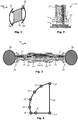
- Fig. 1 shows a schematic illustration of a part of an aircraft cabin 100 having primary structure elements, such as fuselage elements 40, and secondary aircraft cabin structures, such as a cabin partition element 50.
- the cabin partition element 50 may for example be a cockpit wall, a galley separation element or a lavatory wall element.
- the cabin partition element 50 is mounted to the fuselage elements 40 by means of rotary joints 10 in joint regions 30 of which four are exemplarily illustrated in Fig. 1 .
- the location and number of joint regions 30 used to connect secondary aircraft cabin structures to primary structure elements may vary according to the circumstances and the mechanical properties of the secondary aircraft cabin structures and/or the primary structure elements.
- Fig. 4 exemplarily illustrates a cabin partition element 50 as a secondary aircraft cabin structure that may be connected to a primary structure element, such as the fuselage elements 40 of Fig. 1 .
- a primary structure element such as the fuselage elements 40 of Fig. 1 .
- several locations for joint regions 30 are exemplarily depicted at the circumference of the secondary aircraft cabin structure.
- connection of the secondary aircraft cabin structures 50 to the primary structure elements 40 is implemented using connecting struts having separate rotary joint connectors at opposing ends thereof.
- Such connecting struts with separate rotary joint connectors as used in the joint regions 30 and the constituting components and elements thereof are exemplarily shown in various degrees of detail in the Figs. 3 , 5, 6, 7, 8, 9 and 10 .
- Those Figs. exemplarily show schematic illustrations of parts and components as may be used in the aircraft cabin 100 of Fig. 1 , particularly for mounting secondary aircraft cabin structures to primary structure elements in an aircraft cabin.
- the secondary aircraft cabin structures 50 are interconnected to the primary structure elements 40 at joint regions 30.
- Each of the joint regions 30 may have two rotary joints 10 connected to opposing end portions of interconnection struts 20 reaching into the particular joint region 30.
- the framework of joint regions 30 may have a generally two-dimensional layout, i.e. the struts 20 and rotary joints 10 are substantially lying in one plane of extension which may be flat or arcuate.
- the framework of joint regions 30 is coplanar with the plane of the secondary aircraft cabin structure 50 which may be a flat, arcuate or slightly bent wall element of constant or at least only insignificantly varying thickness.
- Fig. 2 shows a cross-sectional view of a rotary joint 10 as may be used at one end of an interconnecting strut in a joint region 30 of the aircraft cabin.
- the rotary joint 10 includes an outer shell segment 1 having the outer shape of a cylinder, particularly a spherical cylinder, or a spheroid or sphere segment.
- the outer shell segment 1 has an opening 4 arranged in the outer surface, for example equidistantly over the outer surface of the outer shell segment 1.
- the opening 4 may for example be cut, milled or bored into the outer surface.
- the opening 4 may as well be included into the joint by virtue of design.
- the shape of the opening 4 may particularly be circular in the plane of the outer surface of the outer shell segment 1; however other shapes like elliptical shapes or rectangular shapes may be possible as well.
- openings of different opening diameter instead of similarly sized openings 4 for different rotary joints 10.
- the rotary joint 10 further includes an inner shell segment 2 having the outer shape of a cylinder, particularly a spherical cylinder, or a spheroid or sphere segment, the inner shell segment 2 being aligned concentrically with the outer shell segment 1. While the inner shell segment 2 and the outer shell segment 1 are connected by connection portions in the boundary regions of the rotary joint 10 (left and right hand side portions of the depicted joint in Fig. 2 ), the inner shell segment 2 is spaced apart from the outer shell segment 1 by a compensation gap in a centre region (the region of the opening 4). In other words, the inner shell segment 2 and the outer shell segment 1 may be connected to each other in regions outside the opening 4, so that the compensation gap is arranged substantially below the opening 4.
- the inner shell segment 2 may be formed integrally with the outer shell segment 1, for example by using a LM manufacturing technology.
- the compensation gap is laterally bounded by the connection portions between the inner and outer shell segments, so that the only access to the compensation gap is through the opening 4 and, optionally, through openings in the inner surface of the inner shell segment 2.
- the rotary joint 10 further comprises a strut holding fixture 11, the strut holding fixture 11 having a hollow interior and a flange portion 13.
- the strut holding fixture 11 has the general shape of a top hat open to both sides, with the flange portion 13 forming the brim of the hat.
- the strut holding fixture 11 may be designed to fit into the shape of the opening 4; that is, the strut holding fixture 11 may have a cylindrical, elliptical or rectangular hollow portion, depending on the choice of shape for the opening 4.
- the strut holding fixture 11 is arranged in the opening 4, so that the flange portion 13 extends within the compensation gap between the inner shell segment 2 and the outer shell segment 1. In Figs.
- the diameter of the hollow portion of the strut holding fixture 11 is lower than the diameter of the opening 4 by a predefined clearance value, so that the outer walls of the strut holding fixture 11 are spaced apart from the inner side walls of the opening 4 by the predefined clearance value.
- the diameter of the flange portion 13 may be greater than the diameter of the opening 4, so that the flange portion 13 extends within the compensation gap below the projection of the opening 4 onto the inner shell segment 2.
- the outer shell segment 1, the inner shell segment 2 and the strut holding fixture 11 may for example be formed as an integral assembly. Such integral assemblies may be conveniently manufactured using an additive layer manufacturing, ALM, technique.
- the strut holding fixtures 11 may be designed as part of a snap-fit or snap-lock mechanism that allows for easy, quick and releasable engagement of struts with the strut holding fixtures 11.
- the strut holding fixtures 11 may comprise a female snap-fit connector, for example by forming slitted side walls in the portion of the fixtures 11 that protrude from the outer shell segment 1. These slitted side walls are outwardly deflectable upon engagement with a male snap-fit connector.
- the side walls of the strut holding fixtures 11 may have a snap securing flange on the far side of the rotary joint body which extends inwardly towards and over the hollow interior. This snap securing flange may secure a male snap-fit connector of a strut engaged with the strut holding fixtures 11 from sliding out of the hollow interior.
- FIG. 10 An exemplary male snap-fit connector with engaging members 21 and 22 is shown in Fig. 10 in cross sectional view.
- the engaging members 21 and 22 may be staggered end portions of gradually declining diameter of an interconnection strut 20, such as the one shown in Figs. 5 and 6 .
- the engaging members 21, 22 are arranged at the respective end portions of each interconnection strut 20 for insertion into the strut holding fixtures 11 of the rotary joints 10.
- An engaging member cover 23 may slidably mounted over the engaging members 21, 22 and may be configured to slide over the respective strut holding fixtures 11 when the engaging members 21, 22 are engaged in order to stabilize and protect the snap-fit connection of the strut 20 with the rotary joint 10.
- the engaging members 21, 22 of the interconnection struts 20 are designed as male snap-fit connectors adapted to snap-lock to the female snap-fit connectors of the strut holding fixtures 11.
- the interconnection struts 20 may comprise a first female-threaded strut section 24 having a hollow cylindrical profile with a female-threaded locking nut 28.
- the first strut section 24 may be female-threaded over a predetermined portion of the end region opposite to the engaging members 21, 22.
- the first strut section 24 is exemplarily shown in Fig. 7 ; the female-threaded locking nut 28 in Fig. 9 , respectively.
- the first strut section 24 is configured to take up a second strut section 25 into the hollow cylindrical profile.
- the second strut section 25, as exemplarily shown in Fig. 8 may have a male-threaded end portion 27, which is insertable or engageable into the hollow cylindrical profile of the first strut section 24, so that the male thread of the end portion 27 of the second strut section 25 may threadingly engage with the female thread of the first strut section 24.
- the male thread of the end portion 27 of the second strut section 25 may further be threadingly engaged with the female thread of the locking nut 28.
- an overall length of the interconnection struts 20 may be selectively adjusted. This may be done by adjusting the percentage of the length of the end portion 27 of the second strut section 25 that extends into the hollow cylindrical profile of the first strut section 24. Finally, when the desired overall length of the struts 20 is adjusted, the locking nut 28 may be fastened to secure the positioning of the strut sections 24 and 25 with respect to each other.
- the second strut section 25 may be equipped at its far end with a respective male snap-fit connector, that is with engaging members 21, 22 and optionally with an engaging member cover 23 as well.
- the struts with strut sections 24 and 25 interconnect two rotary joints 10 at opposing ends thereof which are fixedly coupled to a primary structure element, such as the fuselage portion 40, and a secondary aircraft cabin structure, such as the cabin partition element 50, respectively.
- the joint region 30 as illustrated in Fig. 3 provides for a lateral and rotational decoupling of the secondary aircraft cabin structure from the primary structure element without floating.
- the interconnecting struts may be integrally formed with the rotary joints 10 at the opposing end portions thereof instead of relying on a snap-fit or snap-lock system as illustrated in Fig. 3 .
- the function of the rotary joints 10 is to divert torsional moments acting on the struts 20 lateral to their main axis into the annular shell collar. Since the strut holding fixtures 11 are able to swerve or give way in the plane of the surface of the shell collar upon being stressed with lateral moments, this swivelling motion of the interconnection struts 20 will always be able to compensate for any lateral moments acting on the struts 20. Thus, the force lines will always intersect at the same force line intersection point in the centre of the rotary joint 10, thereby not creating any net moment on the rotary joint 10 as a whole. As a consequence, the rotary joint 10 is free from torsional stress, leading to greater mechanical stability.
- the secondary aircraft cabin structure 50 is fully decoupled from the primary structure element 40 to which it is attached.
- the secondary aircraft cabin structure 50 therefore remains part of the aircraft cabin 100 and does not need to be considered as part of the primary structure of the aircraft.
- reinforcing measures implemented in the primary structure do not need to take into account any of the secondary aircraft cabin structure 50 installed in the aircraft cabin 100.
- a method for mounting a secondary aircraft cabin structure in an aircraft cabin includes engaging a plurality of interconnection struts 20 comprising engaging members 21, 22 at the respective end portions with respective strut holding fixtures 11 of a plurality of rotary joints 10.
- Each of the plurality of rotary joints 10 comprises an outer shell segment 1 having the outer shape of a segment of a solid of revolution, the outer shell segment 1 having an opening 4 arranged in the outer surface, an inner shell segment 2 having the outer shape of the segment of the solid of revolution of the outer shell segment 1, the inner shell segment 2 being aligned concentrically with the outer shell segment 1 and spaced apart from the outer shell segment 1 by a compensation gap, and a strut holding fixture 11 having a hollow interior and a flange portion 13 and being arranged in the opening 4 so that the flange portion 13 extends within the compensation gap between the inner shell segment 2 and the outer shell segment 1.
- the rotary joints 10 are connected at first end portions of the interconnection struts 20 with a primary structure 40 of an aircraft cabin 100, for example at least one fuselage element 40.
- the rotary joints 10 are further connected at second end portions opposite to the first end portions of the interconnection struts 20 with a secondary aircraft cabin structure 50, for example a cabin partition element 50, in particular a cockpit wall.
- a first subset of the plurality of interconnection struts 20 may each comprise a first female-threaded strut section 24 having a hollow cylindrical profile with a female-threaded locking nut 28 and a second strut section 25 having a male-threaded end portion 27, the male-threaded end portion 27 engaged with the hollow cylindrical profile of the first strut section 24 and the female thread of the locking nut 28.
Description
- The present invention relates to an aircraft cabin with secondary aircraft cabin structures mounted to the fuselage with rotary joints, an aircraft having such an aircraft cabin and a method for mounting a secondary aircraft cabin structure in an aircraft cabin using rotary joints.
- Beams, joists and frames for construction work, for example in aeronautics, civil engineering or architecture, are designed to withstand bending forces acting perpendicular to the direction of extension of the respective beams. Conventional beams may be implemented as an integral part with flanges at the edges and a web spanning between the flanges. Alternatively, instead of a web, cutter milled struts may be implemented between parallel running longitudinal support bars, thus leading to decreased weight of the beam due to less material being used to form the beam.
- Local load introduction into such beams or frames may, however, lead to torsional moments that are introduced into the attachment joints of the struts with the longitudinal support bars. Such torsional moments may in turn lead to additional moments within the longitudinal support bars that will have to be compensated for by local strengthening means, thereby nullifying some or all of the weight advantages gained.
- Document
US 6,622,447 B1 discloses a modular structural system for building models and structures, using a plurality of connector hub members with spherical symmetry, and a plurality of strut members with longitudinal symmetry, wherein the strut members are removably engageable with the connector hub members placing the strut members in corresponding radial and tangential positions relative to the connector hub members.Document CA 2 237 020 A1 andDE 38 00 547 A1 each disclose a set of structural elements for producing supporting structures, using supporting bars and cylindrical connecting elements for insertion heads provided on the end sides of the supporting bars. DocumentUS 8,651,914 B2 discloses a set of construction components that may be assembled by connecting male and female snap-lock connectors. A female snap-lock connector includes a deflectable channel opening into a wider cavity; a male snap-lock connector includes a cylindrical head, a neck, and seat. - Document
US 2006/237585 discloses an aircraft cabin where a panel member is attached to the bulkhead members of the fuselage by a plurality of struts. - Document
EP 2921600 discloses a rotary joint and a plurality of interconnection struts. - Cockpit walls, cabin partitions and similar secondary aircraft cabin structures are routinely used to separate cabin space in aircraft. In order to avoid having to reinforce the primary structure of the aircraft, i.e. the fuselage with frames and stringers, deformation and tolerances of the primary structure have to be sufficiently decoupled from the secondary aircraft cabin structures. Typically, attachment mechanisms using floating rod joints, rotationally decoupled lugs or fork/bolt connections have been used hitherto which mechanisms compensate for any deformations and tolerances of the primary structure. However, such mechanisms usually add a lot of undesired system weight and are expensive to implement.
- One object of the invention is to provide solutions for improving the mounting mechanism of secondary aircraft cabin structures to a primary aircraft structure that avoids the transfer of forces between the secondary and primary structures in an efficient and weight saving manner.
This object is achieved by an aircraft cabin having the features of claim 1, an aircraft having the features of claim 7, and a method for mounting a secondary aircraft cabin structure in an aircraft cabin having the features of claim 8. - A first aspect of the disclosure pertains to an aircraft cabin comprising a primary structure, wherein the primary structure comprises at least one fuselage element, a secondary aircraft cabin structure, wherein the secondary aircraft cabin structure comprises a cabin partition element such as a cockpit wall, and wherein the secondary aircraft cabin structure is fully decoupled from the primary structure element to which it is attached; and a plurality of interconnecting struts coupling the primary structure to the secondary aircraft cabin structure, each of the plurality of interconnecting struts comprising engaging members at the respective end portions for insertion into strut holding fixtures of corresponding rotary joints attached at each opposing end. Each of the rotary joints comprises an outer shell segment having the outer shape of a segment of a solid of revolution, the outer shell segment having an opening arranged in the outer surface, an inner shell segment having the outer shape of the segment of the solid of revolution of the outer shell segment, the inner shell segment being aligned concentrically with the outer shell segment and spaced apart from the outer shell segment by a compensation gap, and a strut holding fixture having a hollow interior and a flange portion and being arranged in the opening so that the flange portion extends within the compensation gap between the inner shell segment and the outer shell segment.
According to a second aspect of the disclosure, an aircraft comprises an aircraft cabin according to the first aspect of the disclosure.
According to a third aspect of the disclosure, a method for mounting a secondary aircraft cabin structure in an aircraft cabin comprises engaging a plurality of interconnection struts comprising engaging members at the respective end portions with respective strut holding fixtures of a plurality of rotary joints. Each of the plurality of rotary joints comprises an outer shell segment having the outer shape of a segment of a solid of revolution, the outer shell segment having an opening arranged in the outer surface, an inner shell segment having the outer shape of the segment of the solid of revolution of the outer shell segment, the inner shell segment being aligned concentrically with the outer shell segment and spaced apart from the outer shell segment by a compensation gap, and a strut holding fixture having a hollow interior and a flange portion and being arranged in the opening so that the flange portion extends within the compensation gap between the inner shell segment and the outer shell segment. The method further comprises connecting the rotary joints at first end portions of the interconnection struts with a primary structure of an aircraft cabin, wherein the primary structure comprises at least one fuselage element,, and connecting the rotary joints at second end portions opposite to the first end portions of the interconnection struts with a secondary aircraft cabin structure, wherein the secondary aircraft cabin structure comprises a cabin partition element such as a cockpit wall; and wherein the secondary aircraft cabin structure is fully decoupled from the primary structure element to which it is attached. - The idea on which the present invention is based is to improve the connection nodes of a secondary aircraft cabin structure with a primary structure by employing rotary joints that have two concentrically nested shells of quadric shape. The nested shells are spaced apart by a gap in which sliding members may be formed. The sliding members may in each case be flange portions of holding fixtures that stick out of the outer one of the nested shells through openings or holes in the outer shell. The holding fixtures are designed to engage one end of a connecting strut each, so that a lateral moment on the strut with respect to the outer surface of the nested shells will lead to a shifting movement of the sliding member along the outer surface of the inner one of the shells. Two rotary joints are used on each end of the connecting strut with a first one of the rotary joints decoupling motion from the primary structure into the strut and a second one of the rotary joints decoupling motion from the secondary aircraft cabin structure into the strut.
Thus, any bending moment acting perpendicular to the orientation of the struts will vanish with respect to the annulus made up by the nested shells due to the movement of the sliding members on the surface of the inner shell. This means in turn that the rotary joints will be essentially free of any bending moments that would otherwise be brought into the rotary joints. The axes of the struts will always be oriented towards the centre of symmetry of the rotary joints, thereby balancing out the rotary joints optimally under any loading situation on the struts. In turn, this provides an optimum lateral and rotation decoupling of the secondary aircraft cabin structure with respect to the primary structure. One particular advantage associated with the use of two rotary joints as connection nodes is the implementation of a solution without floating coupling members. This allows for precise positioning of the secondary aircraft cabin structure, specifically of cockpit walls. - Particularly advantageous may additionally be the reduction of costs, weight, lead time, part count and manufacturing complexity coming along with employing any kind of layer manufacturing technology when designing the connection components for the secondary structures, specifically the rotary joints.
- According to an embodiment of the aircraft cabin, the outer shell segment, the inner shell segment and the strut holding fixture may be formed as an integral assembly by an additive layer manufacturing, ALM, technique.
- According to a further embodiment of the aircraft cabin, the diameter of the strut holding fixtures may lower than the diameter of the openings by a predefined clearance value. In some embodiments, the diameter of the flange portion may be greater than the diameter of the opening.
- According to a further embodiment of the aircraft cabin, the plurality of interconnection struts may comprise a first female-threaded strut section having a hollow cylindrical profile with a female-threaded locking nut and a second strut section having a male-threaded end portion, the male-threaded end portion being engageable into the female thread of the locking nut and the female thread of the hollow cylindrical profile of the first female-threaded strut section.
- The invention will be explained in greater detail with reference to exemplary embodiments depicted in the drawings as appended.
- The accompanying drawings are included to provide a further understanding of the present invention and are incorporated in and constitute a part of this specification. The drawings illustrate the embodiments of the present invention and together with the description serve to explain the principles of the invention. Other embodiments of the present invention and many of the intended advantages of the present invention will be readily appreciated as they become better understood by reference to the following detailed description. The elements of the drawings are not necessarily to scale relative to each other. Like reference numerals designate corresponding similar parts.
-
Fig. 1 schematically illustrates an aircraft cabin with secondary aircraft cabin structures mounted to the fuselage with rotary joints according to an embodiment. -
Fig. 2 schematically illustrates a cross sectional view through a rotary joint according to another embodiment. -
Fig. 3 schematically illustrates a cross sectional view through two rotary joints coupled to a connecting strut according to a further embodiment. -
Fig. 4 schematically illustrates a secondary aircraft cabin structure element with connection points according to a further embodiment. -
Fig. 5 schematically illustrates a front view of a connecting strut according to a further embodiment. -
Fig. 6 schematically illustrates a cross sectional view of the connecting strut ofFig. 5 . -
Fig. 7 schematically illustrates a perspective view of a part of the connecting strut ofFig. 5 . -
Fig. 8 schematically illustrates a perspective view of another part of the connecting strut ofFig. 5 . -
Fig. 9 schematically illustrates a perspective view of a locking/securing nut of the connecting strut ofFig. 5 . -
Fig. 10 schematically illustrates a cross sectional view of a detail of the connecting strut ofFig. 5 . - In the figures, like reference numerals denote like or functionally like components, unless indicated otherwise. Any directional terminology like "top", "bottom", "left", "right", "above", "below", "horizontal", "vertical", "back", "front", and similar terms are merely used for explanatory purposes and are not intended to delimit the embodiments to the specific arrangements as shown in the drawings.
- Some of the components, elements and assemblies as disclosed hereinforth may be fabricated using layer manufacturing (LM) methods which free form fabrication (FFF), direct manufacturing (DM) and additive manufacturing (AM) belong to. Those methods are used to form a three-dimensional solid object by sequentially building up layers of material. Any of such procedures will be referred to in the following description as additive layer manufacturing (ALM) or layer manufacturing (LM) without loss of generality. ALM or LM techniques usually include selectively depositing material layer by layer, selectively fusing or solidifying the material and removing excess material, if needed.
- ALM or LM techniques may be used in procedures for building up three-dimensional solid objects based on digital model data. ALM/LM employs an additive process where layers of material are sequentially built up in different shapes. ALM/LM is currently used for prototyping and distributed manufacturing with multiple applications in engineering, construction, industrial design, automotive industries and aerospace industries.
-
Fig. 1 shows a schematic illustration of a part of anaircraft cabin 100 having primary structure elements, such asfuselage elements 40, and secondary aircraft cabin structures, such as acabin partition element 50. Thecabin partition element 50 may for example be a cockpit wall, a galley separation element or a lavatory wall element. Thecabin partition element 50 is mounted to thefuselage elements 40 by means ofrotary joints 10 injoint regions 30 of which four are exemplarily illustrated inFig. 1 . Of course, it should be understood that the location and number ofjoint regions 30 used to connect secondary aircraft cabin structures to primary structure elements may vary according to the circumstances and the mechanical properties of the secondary aircraft cabin structures and/or the primary structure elements. -
Fig. 4 exemplarily illustrates acabin partition element 50 as a secondary aircraft cabin structure that may be connected to a primary structure element, such as thefuselage elements 40 ofFig. 1 . InFig. 4 , several locations forjoint regions 30 are exemplarily depicted at the circumference of the secondary aircraft cabin structure. - Generally, the connection of the secondary
aircraft cabin structures 50 to theprimary structure elements 40 is implemented using connecting struts having separate rotary joint connectors at opposing ends thereof. Such connecting struts with separate rotary joint connectors as used in thejoint regions 30 and the constituting components and elements thereof are exemplarily shown in various degrees of detail in theFigs. 3 ,5, 6, 7, 8, 9 and 10 . Those Figs. exemplarily show schematic illustrations of parts and components as may be used in theaircraft cabin 100 ofFig. 1 , particularly for mounting secondary aircraft cabin structures to primary structure elements in an aircraft cabin. - The secondary
aircraft cabin structures 50 are interconnected to theprimary structure elements 40 atjoint regions 30. Each of thejoint regions 30 may have tworotary joints 10 connected to opposing end portions of interconnection struts 20 reaching into the particularjoint region 30. The framework ofjoint regions 30 may have a generally two-dimensional layout, i.e. thestruts 20 androtary joints 10 are substantially lying in one plane of extension which may be flat or arcuate. In the exemplary case ofFig. 1 the framework ofjoint regions 30 is coplanar with the plane of the secondaryaircraft cabin structure 50 which may be a flat, arcuate or slightly bent wall element of constant or at least only insignificantly varying thickness. -
Fig. 2 shows a cross-sectional view of a rotary joint 10 as may be used at one end of an interconnecting strut in ajoint region 30 of the aircraft cabin. The rotary joint 10 includes an outer shell segment 1 having the outer shape of a cylinder, particularly a spherical cylinder, or a spheroid or sphere segment. The outer shell segment 1 has an opening 4 arranged in the outer surface, for example equidistantly over the outer surface of the outer shell segment 1. The opening 4 may for example be cut, milled or bored into the outer surface. If the rotary joint 10 is manufactured using a LM technique, the opening 4 may as well be included into the joint by virtue of design. The shape of the opening 4 may particularly be circular in the plane of the outer surface of the outer shell segment 1; however other shapes like elliptical shapes or rectangular shapes may be possible as well. - It may also be possible to provide openings of different opening diameter instead of similarly sized openings 4 for different rotary joints 10.
- The rotary joint 10 further includes an
inner shell segment 2 having the outer shape of a cylinder, particularly a spherical cylinder, or a spheroid or sphere segment, theinner shell segment 2 being aligned concentrically with the outer shell segment 1. While theinner shell segment 2 and the outer shell segment 1 are connected by connection portions in the boundary regions of the rotary joint 10 (left and right hand side portions of the depicted joint inFig. 2 ), theinner shell segment 2 is spaced apart from the outer shell segment 1 by a compensation gap in a centre region (the region of the opening 4). In other words, theinner shell segment 2 and the outer shell segment 1 may be connected to each other in regions outside the opening 4, so that the compensation gap is arranged substantially below the opening 4. Theinner shell segment 2 may be formed integrally with the outer shell segment 1, for example by using a LM manufacturing technology. The compensation gap is laterally bounded by the connection portions between the inner and outer shell segments, so that the only access to the compensation gap is through the opening 4 and, optionally, through openings in the inner surface of theinner shell segment 2. - The rotary joint 10 further comprises a
strut holding fixture 11, thestrut holding fixture 11 having a hollow interior and aflange portion 13. Thestrut holding fixture 11 has the general shape of a top hat open to both sides, with theflange portion 13 forming the brim of the hat. Thestrut holding fixture 11 may be designed to fit into the shape of the opening 4; that is, thestrut holding fixture 11 may have a cylindrical, elliptical or rectangular hollow portion, depending on the choice of shape for the opening 4. Thestrut holding fixture 11 is arranged in the opening 4, so that theflange portion 13 extends within the compensation gap between theinner shell segment 2 and the outer shell segment 1. InFigs. 2 and 3 , the diameter of the hollow portion of thestrut holding fixture 11 is lower than the diameter of the opening 4 by a predefined clearance value, so that the outer walls of thestrut holding fixture 11 are spaced apart from the inner side walls of the opening 4 by the predefined clearance value. At the same time, the diameter of theflange portion 13 may be greater than the diameter of the opening 4, so that theflange portion 13 extends within the compensation gap below the projection of the opening 4 onto theinner shell segment 2. The outer shell segment 1, theinner shell segment 2 and thestrut holding fixture 11 may for example be formed as an integral assembly. Such integral assemblies may be conveniently manufactured using an additive layer manufacturing, ALM, technique. - The
strut holding fixtures 11 may be designed as part of a snap-fit or snap-lock mechanism that allows for easy, quick and releasable engagement of struts with thestrut holding fixtures 11. To that end, as exemplarily shown inFigs. 2 and 3 , thestrut holding fixtures 11 may comprise a female snap-fit connector, for example by forming slitted side walls in the portion of thefixtures 11 that protrude from the outer shell segment 1. These slitted side walls are outwardly deflectable upon engagement with a male snap-fit connector. The side walls of thestrut holding fixtures 11 may have a snap securing flange on the far side of the rotary joint body which extends inwardly towards and over the hollow interior. This snap securing flange may secure a male snap-fit connector of a strut engaged with thestrut holding fixtures 11 from sliding out of the hollow interior. - An exemplary male snap-fit connector with engaging
members Fig. 10 in cross sectional view. The engagingmembers interconnection strut 20, such as the one shown inFigs. 5 and 6 . The engagingmembers interconnection strut 20 for insertion into thestrut holding fixtures 11 of the rotary joints 10. An engagingmember cover 23 may slidably mounted over the engagingmembers strut holding fixtures 11 when the engagingmembers strut 20 with the rotary joint 10. - The engaging
members strut holding fixtures 11. In order to provide for interconnection struts of adjustable length, the interconnection struts 20 may comprise a first female-threadedstrut section 24 having a hollow cylindrical profile with a female-threadedlocking nut 28. Thefirst strut section 24 may be female-threaded over a predetermined portion of the end region opposite to the engagingmembers first strut section 24 is exemplarily shown inFig. 7 ; the female-threadedlocking nut 28 inFig. 9 , respectively. Thefirst strut section 24 is configured to take up asecond strut section 25 into the hollow cylindrical profile. Thesecond strut section 25, as exemplarily shown inFig. 8 , may have a male-threadedend portion 27, which is insertable or engageable into the hollow cylindrical profile of thefirst strut section 24, so that the male thread of theend portion 27 of thesecond strut section 25 may threadingly engage with the female thread of thefirst strut section 24. The male thread of theend portion 27 of thesecond strut section 25 may further be threadingly engaged with the female thread of the lockingnut 28. Upon adjusting the position of thesecond strut section 25 with respect to the first female-threadedstrut section 24, an overall length of the interconnection struts 20 may be selectively adjusted. This may be done by adjusting the percentage of the length of theend portion 27 of thesecond strut section 25 that extends into the hollow cylindrical profile of thefirst strut section 24. Finally, when the desired overall length of thestruts 20 is adjusted, the lockingnut 28 may be fastened to secure the positioning of thestrut sections second strut section 25 may be equipped at its far end with a respective male snap-fit connector, that is with engagingmembers member cover 23 as well. - As depicted in
Fig. 3 , the struts withstrut sections rotary joints 10 at opposing ends thereof which are fixedly coupled to a primary structure element, such as thefuselage portion 40, and a secondary aircraft cabin structure, such as thecabin partition element 50, respectively. Thejoint region 30 as illustrated inFig. 3 provides for a lateral and rotational decoupling of the secondary aircraft cabin structure from the primary structure element without floating. The interconnecting struts may be integrally formed with the rotary joints 10 at the opposing end portions thereof instead of relying on a snap-fit or snap-lock system as illustrated inFig. 3 . - The function of the rotary joints 10 is to divert torsional moments acting on the
struts 20 lateral to their main axis into the annular shell collar. Since thestrut holding fixtures 11 are able to swerve or give way in the plane of the surface of the shell collar upon being stressed with lateral moments, this swivelling motion of the interconnection struts 20 will always be able to compensate for any lateral moments acting on thestruts 20. Thus, the force lines will always intersect at the same force line intersection point in the centre of the rotary joint 10, thereby not creating any net moment on the rotary joint 10 as a whole. As a consequence, the rotary joint 10 is free from torsional stress, leading to greater mechanical stability. - Most particularly, the secondary
aircraft cabin structure 50 is fully decoupled from theprimary structure element 40 to which it is attached. The secondaryaircraft cabin structure 50 therefore remains part of theaircraft cabin 100 and does not need to be considered as part of the primary structure of the aircraft. Thus, reinforcing measures implemented in the primary structure do not need to take into account any of the secondaryaircraft cabin structure 50 installed in theaircraft cabin 100. - A method for mounting a secondary aircraft cabin structure in an aircraft cabin includes engaging a plurality of interconnection struts 20 comprising engaging
members strut holding fixtures 11 of a plurality of rotary joints 10. Each of the plurality ofrotary joints 10 comprises an outer shell segment 1 having the outer shape of a segment of a solid of revolution, the outer shell segment 1 having an opening 4 arranged in the outer surface, aninner shell segment 2 having the outer shape of the segment of the solid of revolution of the outer shell segment 1, theinner shell segment 2 being aligned concentrically with the outer shell segment 1 and spaced apart from the outer shell segment 1 by a compensation gap, and astrut holding fixture 11 having a hollow interior and aflange portion 13 and being arranged in the opening 4 so that theflange portion 13 extends within the compensation gap between theinner shell segment 2 and the outer shell segment 1.
The rotary joints 10 are connected at first end portions of the interconnection struts 20 with aprimary structure 40 of anaircraft cabin 100, for example at least onefuselage element 40. The rotary joints 10 are further connected at second end portions opposite to the first end portions of the interconnection struts 20 with a secondaryaircraft cabin structure 50, for example acabin partition element 50, in particular a cockpit wall.
A first subset of the plurality of interconnection struts 20 may each comprise a first female-threadedstrut section 24 having a hollow cylindrical profile with a female-threadedlocking nut 28 and asecond strut section 25 having a male-threadedend portion 27, the male-threadedend portion 27 engaged with the hollow cylindrical profile of thefirst strut section 24 and the female thread of the lockingnut 28.
In the foregoing detailed description, various features are grouped together in one or more examples or examples with the purpose of streamlining the disclosure. It is to be understood that the above description is intended to be illustrative, and not restrictive. Many other examples will be apparent to one skilled in the art upon reviewing the above specification. The invention is limited by the scope of the appended claims. The embodiments were chosen and described in order to best explain the principles of the invention and its practical applications, to thereby enable others skilled in the art to best utilize the invention and various embodiments with various modifications as are suited to the particular use contemplated. In the appended claims and throughout the specification, the terms "including" and "in which" are used as the plain-English equivalents of the respective terms "comprising" and "wherein," respectively. Furthermore, "a" or "one" does not exclude a plurality in the present case. -
- 1
- Outer shell segment
- 2
- Inner shell segment
- 4
- Opening
- 10
- Rotary joint
- 11
- Strut holding fixture
- 13
- Flange portion
- 20
- Interconnection strut
- 21
- Engaging member portion
- 22
- Engaging member portion
- 23
- Engaging member cover
- 24
- First strut section
- 25
- Second strut section
- 27
- Male-threaded end portion
- 28
- Female-threaded locking nut
- 30
- Rotary joint region
- 40
- Fuselage element
- 50
- Cabin partition element
- 100
- Aircraft cabin
Claims (10)
- Aircraft cabin (100), comprising:a primary structure (40);a secondary aircraft cabin structure (50);a plurality of interconnecting struts (20) coupling the primary structure (40) to the secondary aircraft cabin structure (50), each of the plurality of interconnecting struts (20) comprising engaging members (21, 22) at the respective end portions for insertion into strut holding fixtures (11) of corresponding rotary joints (10) attached at each opposing end, each of the rotary joints (10) comprising:an outer shell segment (1) having an outer shape of a segment of a solid of revolution, the outer shell segment (1) having an opening (4) arranged in an outer surface of the outer shell segment;an inner shell segment (2) having the outer shape of the segment of the solid of revolution of the outer shell segment (1), the inner shell segment (2) being aligned concentrically with the outer shell segment (1) and spaced apart from the outer shell segment (1) by a compensation gap; anda strut holding fixture (11) having a hollow interior and a flange portion (13) and being arranged in the opening (4) so that the flange portion (13) extends within the compensation gap between the inner shell segment (2) and the outer shell segment (1);wherein the primary structure (40) comprises at least one fuselage element (40);wherein the secondary aircraft cabin structure (50) comprises a cabin partition element; andwherein the secondary aircraft cabin structure (50) is fully decoupled from the primary structure element (40) to which it is attached.
- Aircraft cabin (100) according to claim 1, wherein the outer shell segment (1), the inner shell segment (2) and the strut holding fixture (11) are formed as an integral assembly by an additive layer manufacturing, ALM, technique.
- Aircraft cabin (100) according to one of the claims 1 and 2, wherein the diameter of the strut holding fixtures (11) is lower than the diameter of the openings (4) by a predefined clearance value.
- Aircraft cabin (100) according to claim 3, wherein the diameter of the flange portion (13) is greater than the diameter of the opening (4).
- Aircraft cabin (100) according to one of the claims 1 to 4, wherein the plurality of interconnection struts (20) comprise a first female-threaded strut section (24) having a hollow cylindrical profile with a female-threaded locking nut (28) and a second strut section (25) having a male-threaded end portion (27), the male-threaded end portion (27) being engageable into the female thread of the locking nut (28) and the female thread of the hollow cylindrical profile of the first female-threaded strut section (24).
- Aircraft cabin (100) according to one of the claims 1 to 5, wherein the secondary aircraft cabin structure (50) comprises a cockpit wall.
- Aircraft, comprising an aircraft cabin (100) according to one of the claims 1 to 6.
- Method for mounting a secondary aircraft cabin structure in an aircraft cabin (100), the method comprising:engaging a plurality of interconnection struts (20) comprising engaging members (21, 22) at the respective end portions with respective strut holding fixtures (11) of a plurality of rotary joints (10), each of the plurality of rotary joints (10) comprising:an outer shell segment (1) having an outer shape of a segment of a solid of revolution, the outer shell segment (1) having an opening (4) arranged in an outer surface of the outer shell segment;an inner shell segment (2) having the outer shape of the segment of the solid of revolution of the outer shell segment (1), the inner shell segment (2) being aligned concentrically with the outer shell segment (1) and spaced apart from the outer shell segment (1) by a compensation gap; anda strut holding fixture (11) having a hollow interior and a flange portion (13) and being arranged in the opening (4) so that the flange portion (13) extends within the compensation gap between the inner shell segment (2) and the outer shell segment (1);connecting the rotary joints (10) at first end portions of the interconnection struts (20) with a primary structure (40) of an aircraft cabin (100); andconnecting the rotary joints (10) at second end portions opposite to the first end portions of the interconnection struts (20) with a secondary aircraft cabin structure (50);wherein the primary structure (40) comprises at least one fuselage element (40);wherein the secondary aircraft cabin structure (50) comprises a cabin partition element; andwherein the secondary aircraft cabin structure (50) is fully decoupled from the primary structure element (40) to which it is attached.
- Method according to claim 8, wherein a first subset of the plurality of interconnection struts (20) each comprise a first female-threaded strut section (24) having a hollow cylindrical profile with a female-threaded locking nut (28) and a second strut section (25) having a male-threaded end portion (27), the male-threaded end portion (27) engaged with the hollow cylindrical profile of the first strut section (24) and the female thread of the locking nut (28).
- Method according to one of the claims 8 and 9, wherein the secondary aircraft cabin structure (50) a cockpit wall.
Priority Applications (1)
| Application Number | Priority Date | Filing Date | Title |
|---|---|---|---|
| EP16183322.3A EP3281860B1 (en) | 2016-08-09 | 2016-08-09 | Aircraft cabin with secondary aircraft cabin structure mounted with rotary joints and method for mounting a secondary aircraft cabin structure in an aircraft cabin |
Applications Claiming Priority (1)
| Application Number | Priority Date | Filing Date | Title |
|---|---|---|---|
| EP16183322.3A EP3281860B1 (en) | 2016-08-09 | 2016-08-09 | Aircraft cabin with secondary aircraft cabin structure mounted with rotary joints and method for mounting a secondary aircraft cabin structure in an aircraft cabin |
Publications (2)
| Publication Number | Publication Date |
|---|---|
| EP3281860A1 EP3281860A1 (en) | 2018-02-14 |
| EP3281860B1 true EP3281860B1 (en) | 2018-10-17 |
Family
ID=56615903
Family Applications (1)
| Application Number | Title | Priority Date | Filing Date |
|---|---|---|---|
| EP16183322.3A Active EP3281860B1 (en) | 2016-08-09 | 2016-08-09 | Aircraft cabin with secondary aircraft cabin structure mounted with rotary joints and method for mounting a secondary aircraft cabin structure in an aircraft cabin |
Country Status (1)
| Country | Link |
|---|---|
| EP (1) | EP3281860B1 (en) |
Families Citing this family (1)
| Publication number | Priority date | Publication date | Assignee | Title |
|---|---|---|---|---|
| DE102019111001A1 (en) | 2019-04-29 | 2020-10-29 | Airbus Operations Gmbh | Tolerance compensation assembly, aircraft components provided therewith and aircraft |
Family Cites Families (8)
| Publication number | Priority date | Publication date | Assignee | Title |
|---|---|---|---|---|
| DE3800547A1 (en) | 1988-01-12 | 1989-07-27 | Octanorm Vertriebs Gmbh | KIT FOR THE PRODUCTION OF STRUCTURES |
| DE19544076C1 (en) | 1995-11-25 | 1997-04-30 | Expo Mart Inc | Kit for the production of structures from supporting rods and connecting elements |
| US6622447B1 (en) | 1996-11-21 | 2003-09-23 | Steven Crawford Kessler | Modular hub and strut structural system |
| US7455263B2 (en) * | 2005-04-22 | 2008-11-25 | The Boeing Company | Airplane interior systems |
| US7762496B2 (en) * | 2005-12-02 | 2010-07-27 | The Boeing Company | Overhead flight crew rest |
| US8651914B2 (en) | 2006-01-27 | 2014-02-18 | Costas Sisamos | Snap-lock construction toy |
| US8387918B2 (en) * | 2006-09-15 | 2013-03-05 | The Boeing Company | Multi-directional support arm |
| EP2921600B1 (en) * | 2014-03-19 | 2016-05-18 | Airbus Operations GmbH | Rotary joint, framework construction kit and method for constructing a framework |
-
2016
- 2016-08-09 EP EP16183322.3A patent/EP3281860B1/en active Active
Non-Patent Citations (1)
| Title |
|---|
| None * |
Also Published As
| Publication number | Publication date |
|---|---|
| EP3281860A1 (en) | 2018-02-14 |
Similar Documents
| Publication | Publication Date | Title |
|---|---|---|
| EP2921600B1 (en) | Rotary joint, framework construction kit and method for constructing a framework | |
| US10458463B2 (en) | Rotary joint, framework construction kit and method for manufacturing a rotary joint | |
| US10378198B2 (en) | Rotary joint, framework construction kit, framework with rotary joints and method for manufacturing a rotary joint | |
| US10087981B2 (en) | Joint connector, rotary joint, framework construction kit and framework | |
| EP2371706B1 (en) | Torsion box with rib fitting | |
| EP3173331B1 (en) | Cover panel for a structural component | |
| CN106585999B (en) | Aircraft engine pylon | |
| EP3345754B1 (en) | Sandwich panel with recessed channel network | |
| EP3838739B1 (en) | Compression chord for a fuselage | |
| EP3173330A1 (en) | Rod connection system, structural aircraft component and connector stud | |
| EP2700573B1 (en) | A pressurized airplane fuselage, comprising a pressure bulkhead | |
| EP3095689B1 (en) | A pressure bulkhead for an aircraft fuselage | |
| CN102576931A (en) | Radome and device for attaching said radome to an aircraft | |
| EP3838741A1 (en) | Longitudinal beam joint for a pressure deck assembly | |
| EP3281860B1 (en) | Aircraft cabin with secondary aircraft cabin structure mounted with rotary joints and method for mounting a secondary aircraft cabin structure in an aircraft cabin | |
| CN108238261B (en) | Main structure for a support for an aircraft propeller group comprising a pyramidal section with convergent struts | |
| CN107264771A (en) | Pressure bulkhead device | |
| US9446834B2 (en) | Self-stiffened skin for aircraft fuselage including stringers with a closed section and associated manufacturing method | |
| US10612582B2 (en) | Tie rod and method for manufacturing a tie rod | |
| CN111003184A (en) | Aircraft external hanging article support | |
| EP3470326B1 (en) | Structural panel with complex framework |
Legal Events
| Date | Code | Title | Description |
|---|---|---|---|
| PUAI | Public reference made under article 153(3) epc to a published international application that has entered the european phase |
Free format text: ORIGINAL CODE: 0009012 |
|
| STAA | Information on the status of an ep patent application or granted ep patent |
Free format text: STATUS: THE APPLICATION HAS BEEN PUBLISHED |
|
| AK | Designated contracting states |
Kind code of ref document: A1 Designated state(s): AL AT BE BG CH CY CZ DE DK EE ES FI FR GB GR HR HU IE IS IT LI LT LU LV MC MK MT NL NO PL PT RO RS SE SI SK SM TR |
|
| AX | Request for extension of the european patent |
Extension state: BA ME |
|
| STAA | Information on the status of an ep patent application or granted ep patent |
Free format text: STATUS: REQUEST FOR EXAMINATION WAS MADE |
|
| 17P | Request for examination filed |
Effective date: 20180418 |
|
| RBV | Designated contracting states (corrected) |
Designated state(s): AL AT BE BG CH CY CZ DE DK EE ES FI FR GB GR HR HU IE IS IT LI LT LU LV MC MK MT NL NO PL PT RO RS SE SI SK SM TR |
|
| GRAP | Despatch of communication of intention to grant a patent |
Free format text: ORIGINAL CODE: EPIDOSNIGR1 |
|
| STAA | Information on the status of an ep patent application or granted ep patent |
Free format text: STATUS: GRANT OF PATENT IS INTENDED |
|
| INTG | Intention to grant announced |
Effective date: 20180619 |
|
| GRAS | Grant fee paid |
Free format text: ORIGINAL CODE: EPIDOSNIGR3 |
|
| GRAA | (expected) grant |
Free format text: ORIGINAL CODE: 0009210 |
|
| STAA | Information on the status of an ep patent application or granted ep patent |
Free format text: STATUS: THE PATENT HAS BEEN GRANTED |
|
| AK | Designated contracting states |
Kind code of ref document: B1 Designated state(s): AL AT BE BG CH CY CZ DE DK EE ES FI FR GB GR HR HU IE IS IT LI LT LU LV MC MK MT NL NO PL PT RO RS SE SI SK SM TR |
|
| REG | Reference to a national code |
Ref country code: GB Ref legal event code: FG4D |
|
| REG | Reference to a national code |
Ref country code: CH Ref legal event code: EP |
|
| REG | Reference to a national code |
Ref country code: IE Ref legal event code: FG4D |
|
| REG | Reference to a national code |
Ref country code: DE Ref legal event code: R096 Ref document number: 602016006458 Country of ref document: DE Ref country code: AT Ref legal event code: REF Ref document number: 1053680 Country of ref document: AT Kind code of ref document: T Effective date: 20181115 |
|
| REG | Reference to a national code |
Ref country code: NL Ref legal event code: MP Effective date: 20181017 |
|
| REG | Reference to a national code |
Ref country code: LT Ref legal event code: MG4D |
|
| REG | Reference to a national code |
Ref country code: AT Ref legal event code: MK05 Ref document number: 1053680 Country of ref document: AT Kind code of ref document: T Effective date: 20181017 |
|
| PG25 | Lapsed in a contracting state [announced via postgrant information from national office to epo] |
Ref country code: NL Free format text: LAPSE BECAUSE OF FAILURE TO SUBMIT A TRANSLATION OF THE DESCRIPTION OR TO PAY THE FEE WITHIN THE PRESCRIBED TIME-LIMIT Effective date: 20181017 |
|
| PG25 | Lapsed in a contracting state [announced via postgrant information from national office to epo] |
Ref country code: ES Free format text: LAPSE BECAUSE OF FAILURE TO SUBMIT A TRANSLATION OF THE DESCRIPTION OR TO PAY THE FEE WITHIN THE PRESCRIBED TIME-LIMIT Effective date: 20181017 Ref country code: AT Free format text: LAPSE BECAUSE OF FAILURE TO SUBMIT A TRANSLATION OF THE DESCRIPTION OR TO PAY THE FEE WITHIN THE PRESCRIBED TIME-LIMIT Effective date: 20181017 Ref country code: BG Free format text: LAPSE BECAUSE OF FAILURE TO SUBMIT A TRANSLATION OF THE DESCRIPTION OR TO PAY THE FEE WITHIN THE PRESCRIBED TIME-LIMIT Effective date: 20190117 Ref country code: NO Free format text: LAPSE BECAUSE OF FAILURE TO SUBMIT A TRANSLATION OF THE DESCRIPTION OR TO PAY THE FEE WITHIN THE PRESCRIBED TIME-LIMIT Effective date: 20190117 Ref country code: IS Free format text: LAPSE BECAUSE OF FAILURE TO SUBMIT A TRANSLATION OF THE DESCRIPTION OR TO PAY THE FEE WITHIN THE PRESCRIBED TIME-LIMIT Effective date: 20190217 Ref country code: LT Free format text: LAPSE BECAUSE OF FAILURE TO SUBMIT A TRANSLATION OF THE DESCRIPTION OR TO PAY THE FEE WITHIN THE PRESCRIBED TIME-LIMIT Effective date: 20181017 Ref country code: FI Free format text: LAPSE BECAUSE OF FAILURE TO SUBMIT A TRANSLATION OF THE DESCRIPTION OR TO PAY THE FEE WITHIN THE PRESCRIBED TIME-LIMIT Effective date: 20181017 Ref country code: LV Free format text: LAPSE BECAUSE OF FAILURE TO SUBMIT A TRANSLATION OF THE DESCRIPTION OR TO PAY THE FEE WITHIN THE PRESCRIBED TIME-LIMIT Effective date: 20181017 Ref country code: PL Free format text: LAPSE BECAUSE OF FAILURE TO SUBMIT A TRANSLATION OF THE DESCRIPTION OR TO PAY THE FEE WITHIN THE PRESCRIBED TIME-LIMIT Effective date: 20181017 Ref country code: HR Free format text: LAPSE BECAUSE OF FAILURE TO SUBMIT A TRANSLATION OF THE DESCRIPTION OR TO PAY THE FEE WITHIN THE PRESCRIBED TIME-LIMIT Effective date: 20181017 |
|
| PG25 | Lapsed in a contracting state [announced via postgrant information from national office to epo] |
Ref country code: SE Free format text: LAPSE BECAUSE OF FAILURE TO SUBMIT A TRANSLATION OF THE DESCRIPTION OR TO PAY THE FEE WITHIN THE PRESCRIBED TIME-LIMIT Effective date: 20181017 Ref country code: RS Free format text: LAPSE BECAUSE OF FAILURE TO SUBMIT A TRANSLATION OF THE DESCRIPTION OR TO PAY THE FEE WITHIN THE PRESCRIBED TIME-LIMIT Effective date: 20181017 Ref country code: AL Free format text: LAPSE BECAUSE OF FAILURE TO SUBMIT A TRANSLATION OF THE DESCRIPTION OR TO PAY THE FEE WITHIN THE PRESCRIBED TIME-LIMIT Effective date: 20181017 Ref country code: PT Free format text: LAPSE BECAUSE OF FAILURE TO SUBMIT A TRANSLATION OF THE DESCRIPTION OR TO PAY THE FEE WITHIN THE PRESCRIBED TIME-LIMIT Effective date: 20190217 Ref country code: GR Free format text: LAPSE BECAUSE OF FAILURE TO SUBMIT A TRANSLATION OF THE DESCRIPTION OR TO PAY THE FEE WITHIN THE PRESCRIBED TIME-LIMIT Effective date: 20190118 |
|
| REG | Reference to a national code |
Ref country code: DE Ref legal event code: R097 Ref document number: 602016006458 Country of ref document: DE |
|
| PG25 | Lapsed in a contracting state [announced via postgrant information from national office to epo] |
Ref country code: DK Free format text: LAPSE BECAUSE OF FAILURE TO SUBMIT A TRANSLATION OF THE DESCRIPTION OR TO PAY THE FEE WITHIN THE PRESCRIBED TIME-LIMIT Effective date: 20181017 Ref country code: CZ Free format text: LAPSE BECAUSE OF FAILURE TO SUBMIT A TRANSLATION OF THE DESCRIPTION OR TO PAY THE FEE WITHIN THE PRESCRIBED TIME-LIMIT Effective date: 20181017 Ref country code: IT Free format text: LAPSE BECAUSE OF FAILURE TO SUBMIT A TRANSLATION OF THE DESCRIPTION OR TO PAY THE FEE WITHIN THE PRESCRIBED TIME-LIMIT Effective date: 20181017 |
|
| PLBE | No opposition filed within time limit |
Free format text: ORIGINAL CODE: 0009261 |
|
| STAA | Information on the status of an ep patent application or granted ep patent |
Free format text: STATUS: NO OPPOSITION FILED WITHIN TIME LIMIT |
|
| PG25 | Lapsed in a contracting state [announced via postgrant information from national office to epo] |
Ref country code: SK Free format text: LAPSE BECAUSE OF FAILURE TO SUBMIT A TRANSLATION OF THE DESCRIPTION OR TO PAY THE FEE WITHIN THE PRESCRIBED TIME-LIMIT Effective date: 20181017 Ref country code: RO Free format text: LAPSE BECAUSE OF FAILURE TO SUBMIT A TRANSLATION OF THE DESCRIPTION OR TO PAY THE FEE WITHIN THE PRESCRIBED TIME-LIMIT Effective date: 20181017 Ref country code: EE Free format text: LAPSE BECAUSE OF FAILURE TO SUBMIT A TRANSLATION OF THE DESCRIPTION OR TO PAY THE FEE WITHIN THE PRESCRIBED TIME-LIMIT Effective date: 20181017 Ref country code: SM Free format text: LAPSE BECAUSE OF FAILURE TO SUBMIT A TRANSLATION OF THE DESCRIPTION OR TO PAY THE FEE WITHIN THE PRESCRIBED TIME-LIMIT Effective date: 20181017 |
|
| 26N | No opposition filed |
Effective date: 20190718 |
|
| PG25 | Lapsed in a contracting state [announced via postgrant information from national office to epo] |
Ref country code: TR Free format text: LAPSE BECAUSE OF FAILURE TO SUBMIT A TRANSLATION OF THE DESCRIPTION OR TO PAY THE FEE WITHIN THE PRESCRIBED TIME-LIMIT Effective date: 20181017 |
|
| PG25 | Lapsed in a contracting state [announced via postgrant information from national office to epo] |
Ref country code: LI Free format text: LAPSE BECAUSE OF NON-PAYMENT OF DUE FEES Effective date: 20190831 Ref country code: CH Free format text: LAPSE BECAUSE OF NON-PAYMENT OF DUE FEES Effective date: 20190831 Ref country code: MC Free format text: LAPSE BECAUSE OF FAILURE TO SUBMIT A TRANSLATION OF THE DESCRIPTION OR TO PAY THE FEE WITHIN THE PRESCRIBED TIME-LIMIT Effective date: 20181017 Ref country code: LU Free format text: LAPSE BECAUSE OF NON-PAYMENT OF DUE FEES Effective date: 20190809 |
|
| REG | Reference to a national code |
Ref country code: BE Ref legal event code: MM Effective date: 20190831 |
|
| PG25 | Lapsed in a contracting state [announced via postgrant information from national office to epo] |
Ref country code: IE Free format text: LAPSE BECAUSE OF NON-PAYMENT OF DUE FEES Effective date: 20190809 |
|
| PG25 | Lapsed in a contracting state [announced via postgrant information from national office to epo] |
Ref country code: BE Free format text: LAPSE BECAUSE OF NON-PAYMENT OF DUE FEES Effective date: 20190831 |
|
| PG25 | Lapsed in a contracting state [announced via postgrant information from national office to epo] |
Ref country code: CY Free format text: LAPSE BECAUSE OF FAILURE TO SUBMIT A TRANSLATION OF THE DESCRIPTION OR TO PAY THE FEE WITHIN THE PRESCRIBED TIME-LIMIT Effective date: 20181017 |
|
| PG25 | Lapsed in a contracting state [announced via postgrant information from national office to epo] |
Ref country code: MT Free format text: LAPSE BECAUSE OF FAILURE TO SUBMIT A TRANSLATION OF THE DESCRIPTION OR TO PAY THE FEE WITHIN THE PRESCRIBED TIME-LIMIT Effective date: 20181017 Ref country code: HU Free format text: LAPSE BECAUSE OF FAILURE TO SUBMIT A TRANSLATION OF THE DESCRIPTION OR TO PAY THE FEE WITHIN THE PRESCRIBED TIME-LIMIT; INVALID AB INITIO Effective date: 20160809 |
|
| PG25 | Lapsed in a contracting state [announced via postgrant information from national office to epo] |
Ref country code: SI Free format text: LAPSE BECAUSE OF FAILURE TO SUBMIT A TRANSLATION OF THE DESCRIPTION OR TO PAY THE FEE WITHIN THE PRESCRIBED TIME-LIMIT Effective date: 20181017 |
|
| PG25 | Lapsed in a contracting state [announced via postgrant information from national office to epo] |
Ref country code: MK Free format text: LAPSE BECAUSE OF FAILURE TO SUBMIT A TRANSLATION OF THE DESCRIPTION OR TO PAY THE FEE WITHIN THE PRESCRIBED TIME-LIMIT Effective date: 20181017 |
|
| PGFP | Annual fee paid to national office [announced via postgrant information from national office to epo] |
Ref country code: GB Payment date: 20230822 Year of fee payment: 8 |
|
| PGFP | Annual fee paid to national office [announced via postgrant information from national office to epo] |
Ref country code: FR Payment date: 20230825 Year of fee payment: 8 Ref country code: DE Payment date: 20230821 Year of fee payment: 8 |