EP3281779A1 - Manufacturing method and manufacturing device for rolled rubber member - Google Patents
Manufacturing method and manufacturing device for rolled rubber member Download PDFInfo
- Publication number
- EP3281779A1 EP3281779A1 EP16776563.5A EP16776563A EP3281779A1 EP 3281779 A1 EP3281779 A1 EP 3281779A1 EP 16776563 A EP16776563 A EP 16776563A EP 3281779 A1 EP3281779 A1 EP 3281779A1
- Authority
- EP
- European Patent Office
- Prior art keywords
- rubber
- rubber layer
- thread
- rolled member
- layer
- Prior art date
- Legal status (The legal status is an assumption and is not a legal conclusion. Google has not performed a legal analysis and makes no representation as to the accuracy of the status listed.)
- Granted
Links
Images

Classifications
-
- B—PERFORMING OPERATIONS; TRANSPORTING
- B29—WORKING OF PLASTICS; WORKING OF SUBSTANCES IN A PLASTIC STATE IN GENERAL
- B29D—PRODUCING PARTICULAR ARTICLES FROM PLASTICS OR FROM SUBSTANCES IN A PLASTIC STATE
- B29D30/00—Producing pneumatic or solid tyres or parts thereof
- B29D30/06—Pneumatic tyres or parts thereof (e.g. produced by casting, moulding, compression moulding, injection moulding, centrifugal casting)
- B29D30/38—Textile inserts, e.g. cord or canvas layers, for tyres; Treatment of inserts prior to building the tyre
-
- B—PERFORMING OPERATIONS; TRANSPORTING
- B29—WORKING OF PLASTICS; WORKING OF SUBSTANCES IN A PLASTIC STATE IN GENERAL
- B29C—SHAPING OR JOINING OF PLASTICS; SHAPING OF MATERIAL IN A PLASTIC STATE, NOT OTHERWISE PROVIDED FOR; AFTER-TREATMENT OF THE SHAPED PRODUCTS, e.g. REPAIRING
- B29C43/00—Compression moulding, i.e. applying external pressure to flow the moulding material; Apparatus therefor
- B29C43/22—Compression moulding, i.e. applying external pressure to flow the moulding material; Apparatus therefor of articles of indefinite length
- B29C43/24—Calendering
-
- B—PERFORMING OPERATIONS; TRANSPORTING
- B29—WORKING OF PLASTICS; WORKING OF SUBSTANCES IN A PLASTIC STATE IN GENERAL
- B29C—SHAPING OR JOINING OF PLASTICS; SHAPING OF MATERIAL IN A PLASTIC STATE, NOT OTHERWISE PROVIDED FOR; AFTER-TREATMENT OF THE SHAPED PRODUCTS, e.g. REPAIRING
- B29C43/00—Compression moulding, i.e. applying external pressure to flow the moulding material; Apparatus therefor
- B29C43/32—Component parts, details or accessories; Auxiliary operations
- B29C43/44—Compression means for making articles of indefinite length
- B29C43/46—Rollers
-
- B—PERFORMING OPERATIONS; TRANSPORTING
- B29—WORKING OF PLASTICS; WORKING OF SUBSTANCES IN A PLASTIC STATE IN GENERAL
- B29D—PRODUCING PARTICULAR ARTICLES FROM PLASTICS OR FROM SUBSTANCES IN A PLASTIC STATE
- B29D30/00—Producing pneumatic or solid tyres or parts thereof
- B29D30/06—Pneumatic tyres or parts thereof (e.g. produced by casting, moulding, compression moulding, injection moulding, centrifugal casting)
- B29D30/38—Textile inserts, e.g. cord or canvas layers, for tyres; Treatment of inserts prior to building the tyre
- B29D2030/381—Textile inserts, e.g. cord or canvas layers, for tyres; Treatment of inserts prior to building the tyre the inserts incorporating reinforcing parallel cords; manufacture thereof
Definitions
- the present invention relates to a method and device for manufacturing a rubber rolled member that is used in pneumatic tires, and in further detail, relates to a manufacturing method and manufacturing device for a rubber rolled member that can effectively suppress blister defects and that improves the air dispersibility during vulcanizing at the rubber layer interface.
- Vulcanizing defects known as blister defects may occur when vulcanizing pneumatic tires.
- Blister defects are defects where moisture and residual air included in rubber, as well as residual air remaining in steps that are formed at an end part of tire component members during tire formation are locally collected during vulcanizing, and the resulting air bubbles form a blister without dispersing during vulcanizing, and thus remain in the tire.
- the moisture and residual air that are included in rubber form countless bubbles during initial stage of vulcanization, and most of the bubbles are eliminated by microdispersion during vulcanizing.
- gas bubbles collect in areas where the pressurizing force is weak during microdispersion, and bubbles may reoccur to form blisters after vulcanizing is complete.
- the tire component member is pressed by a stitcher during tire formation to promote air dispersion, and air is discharged through vent holes provided on the inner surface of the mold during vulcanizing, but the residual air inside the tire cannot be sufficiently discharged simply by this method.
- the organic fiber cord for absorbing air which is not rubber coated is provided on at least one surface of the carcass layer as described above, while the residual air between the carcass layer and the adjacent members can be absorbed, at the present, blister defects cannot necessarily be effectively suppressed. Furthermore, if the organic fiber cord for absorbing air that is not rubber coated is provided on the surface of the carcass layer, there is a possibility that the organic fiber cord will detach or become misaligned during the tire forming step.
- Patent Document 1 US Patent Application No. 2013/035555
- An object of the present invention is to provide a manufacturing method and manufacturing device for a rubber rolled member that can effectively suppress blister defects and that improves the air dispersibility during vulcanizing at the rubber layer interface.
- the manufacturing method of a rubber rolled member of the present invention for achieving the aforementioned object includes the steps of: forming a first rubber layer by a first pair of rolling rollers; forming a second rubber layer by a second pair of rolling rollers; and layering the first rubber layer and the second rubber layer together to manufacture a rubber rolled member; at least one independently supplied thread being inserted between the first rubber layer and the second number layer, and the thread being embedded in the longitudinal direction of the rubber rolled member.
- the manufacturing device for a rubber rolled member of the present invention for achieving the aforementioned object includes: a first pair of rolling rollers that form the first rubber layer; a second pair of rolling rollers that form the second rubber rolled member; a layering device that layers the first rubber layer and the second rubber layer together; and an insertion device that inserts at least one independently supplied thread between the first rubber layer and the second rubber layer.
- the present invention improves air dispersibility during vulcanizing at the interface between the first rubber layer and the second rubber layer, and can effectively suppress blister defects by inserting at least one independently supplied thread between the first rubber layer and the second rubber layer, and embedding the thread along the longitudinal direction of the rubber rolled member. Furthermore, when arranging the thread between the first rubber layer and the second rubber layer constituting the rubber rolled member, detaching and misaligning of the thread will not occur during the tire forming step, and therefore there is also an advantage that the tire forming step can be smoothly performed.
- the first rubber layer and the second rubber layer can be formed from mutually different rubbers.
- a case where the first rubber layer corresponding to the inner liner layer and the second rubber layer corresponding to the tie rubber layer are layered together to manufacture a rubber rolled member is suitable.
- the breaking strength of the thread is preferably 100 N or less.
- the thread is provided to improve the air dispersibility and is not a reinforcing member, so the effect on the behavior of the rubber rolled member during the tire forming process can be suppressed to a minimum by specifying the upper limit of the breaking strength.
- the cord density of the thread is preferably 5 strands/50 mm or less.
- the thread is provided to improve the air dispersibility and is not a reinforcing member, so the effect on the behavior of the rubber rolled member during the tire forming process can be suppressed to a minimum by specifying the upper limit of the cord density.
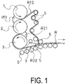
- FIG. 1 illustrates a manufacturing device for a rubber rolled member which is an embodiment of the present invention.
- the manufacturing device of the rubber rolled member of the present embodiment has three rolling rollers 1 to 3 provided with mutually parallel rotational axes.
- the first pair of rolling rollers 1, 2 are configured so as to rotate in mutually opposite directions while maintaining a gap between the outer circumferential surfaces. Therefore, the rubber R11 is held in a bank on the opposite side as the direction of rotation of the rolling rollers 1, 2, and a first rubber layer R12 with a pre-determined thickness is formed by the rubber R11 passing through the rolling rollers 1, 2.
- the second pair of rolling rollers 2, 3 are configured so as to rotate in mutually opposite directions while maintaining a gap between the outer circumferential surfaces. Therefore, the rubber R21 is held in a bank on the opposite side as the direction of rotation of the rolling rollers 2, 3, and a second rubber layer R22 with a pre-determined thickness is formed by the rubber R21 passing through the rolling rollers 2, 3.
- the first rubber layer R12 and the second rubber layer R22 are guided by a guide roller 5 and provided to a layering device 6.
- the layering device 6 integrally compression bonds the mutually layered first rubber layer R12 and second rubber layer R22, and discharges a rubber rolled member R.
- This type of layering device 6 can be configured from a pair of rollers.
- the aforementioned manufacturing device for a rubber rolled member has a thread inserting device 7 that inserts at least one strand of thread S between the first rubber layer R12 and the second rubber layer R22.
- the thread inserting device 7 has a bobbin on which the thread S is wound, and the thread S is continuously supplied from the bobbin.
- This type of thread inserting device 7 can be installed at a plurality of locations in the width direction of the rubber rolled member R.
- the thread S is supplied in an independent form that does not configure a fabric.
- the thread S is automatically fed out from the thread inserting device 7 in conjunction with the rubber rolled member R being discharged because the thread is sandwiched between the first rubber layer R12 and the second rubber layer R22.
- the rubber R11 is rolled by the first pair of rolling rollers 1, 2 to form the first rubber layer R12, while at the same time, the rubber R21 is rolled by the second pair of rolling rollers 2, 3 to form the second rubber layer R22. Furthermore, the rubber rolled member R is continuously manufactured by layering the first rubber layer R12 and the second rubber layer R22 together in the layering device 6. At this time, the thread S can be embedded in the longitudinal direction of the rubber rolled member R by having at least one thread S independently supplied and inserted by the thread inserting device 7 between the first rubber layer R12 and the second rubber layer R22.
- FIG. 2 illustrates the manufacturing device for the rubber rolled member according to another embodiment of the present invention.
- the manufacturing device of the rubber rolled member of the present embodiment has four rolling rollers 1 to 4 provided with mutually parallel rotational axes.
- the first pair of rolling rollers 1, 2 are configured so as to rotate in mutually opposite directions while maintaining a gap between the outer circumferential surfaces. Therefore, the rubber R11 is held in a bank on the opposite side as the direction of rotation of the rolling rollers 1, 2, and a first rubber layer R12 with a pre-determined thickness is formed by the rubber R11 passing through the rolling rollers 1, 2.
- the second pair of rolling rollers 3, 4 are configured so as to rotate in mutually opposite directions while maintaining a gap between the outer circumferential surfaces. Therefore, the rubber R21 is held in a bank on the opposite side as the direction of rotation of the rolling rollers 3, 4, and a second rubber layer R22 with a pre-determined thickness is formed by the rubber R21 passing through the rolling rollers 3, 4.
- the first rubber layer R12 and the second rubber layer R22 are guided by a guide roller 5 and provided to a layering device 6.
- the layering device 6 integrally compression bonds the layered first rubber layer R12 and second rubber layer R22, and discharges a rubber rolled member R.
- the thread inserting device 7 is installed to insert at least one strand of thread S that is independently supplied between the first rubber layer R12 and the second rubber layer R22.
- the rubber R11 is rolled by the first pair of rolling rollers 1, 2 to form the first rubber layer R12, while at the same time, the rubber R21 is rolled by the second pair of rolling rollers 3, 4 to form the second rubber layer R22. Furthermore, the rubber rolled member R is continuously manufactured by layering the first rubber layer R12 and the second rubber layer R22 together in the layering device 6. At this time, the thread S can be embedded in the longitudinal direction of the rubber rolled member R by having at least one thread S independently supplied and inserted by the thread inserting device 7 between the first rubber layer R12 and the second rubber layer R22.
- At least one strand of thread S is independently supplied and is inserted between the first rubber layer R12 and the second rubber layer R22, and the thread S is embedded in the longitudinal direction of the rubber rolled member R, and thereby improves air dispersibility during vulcanizing at the interface between the first rubber layer R11 and the second rubber layer R21, and can effectively suppress blister defects. Furthermore, when arranging the thread S between the first rubber layer R12 and the second rubber layer R22 constituting the rubber rolled member R, detaching and misaligning of the thread S will not occur during the tire forming step, and therefore there is also an advantage that the tire forming step can be smoothly performed.
- the breaking strength of the thread S is preferably 100 N or less, and more preferably 1 N to 5 N.
- This thread S is provided to improve the air dispersibility and is not a reinforcing member, so the effect on the behavior of the rubber rolled member R during the tire forming process can be suppressed to a minimum by specifying the upper limit of the breaking strength. If the breaking strength of the thread S is too high, there is a possibility of having a negative effect on the tire forming process.
- the component material of the thread S is not particularly restricted, but for example, synthetic fiber such as nylon, polyester, rayon, and the like, or natural fibers such as cotton or the like can be used. Furthermore, the total linear density of the thread S is preferably within a range of 25 dtex to 170 dtex. Thereby, favorable air dispersibility can be ensured while keeping the breaking strength low.
- the cord density of the thread is preferably 5 strands/50 mm or less.
- This thread S is provided to improve the air dispersibility and is not a reinforcing member, so the effect on the behavior of the rubber rolled member during the tire forming process can be suppressed to a minimum by specifying the upper limit of the cord density. If the cord density of the thread S is too high, there is a possibility of having a negative effect on the tire forming process.
- the cord density of the thread S is specified by a mutual interval. For example, if the mutual interval of the thread S is P mm, the cord density (strand/50 mm) of the thread S will be 50/P. Furthermore, if the cord count of the thread S at the interface is 1 strand, the cord density can be considered to be 5 strands/50 mm or less.
- FIG. 3 illustrates an example of the rubber rolled member obtained by the present invention.
- the rubber rolled member R is made by layering the first rubber layer R12 corresponding to the inner liner layer and the second rubber layer R22 corresponding to the tie rubber layer together. With the rubber rolled member R, a plurality of strands of thread S that extend in the longitudinal direction are provided at a predetermined interval in the width direction of the rubber rolled member R.
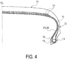
- FIG. 4 illustrates one example of a pneumatic tire obtained by the present invention.
- FIG. 4 illustrates only a portion of one side of the tire centerline CL, but this pneumatic tire has a configuration that also corresponds to the other side of the tire centerline CL.
- FIGS. 4 11 is a tread portion, 12 is a sidewall portion, and 13 is a bead portion.
- Two carcass layers 14 including a plurality of reinforcing cords extending in a tire radial direction are laid between a pair of left and right bead portions 13,13. Ends of the carcass layers 14 are folded around a bead cores 15 from a tire inner side to a tire outer side.
- a bead filler 16 formed from a rubber composition having a high degree of hardness is disposed on peripheries of the bead cores 15, and the bead filler 16 is encompassed by the carcass layer 14.
- a plurality of belt layers 17 is embedded on the outer circumferential side of the carcass layer 14 in the tread portion 11.
- These belt layers 17 include a plurality of reinforcing cords that are inclined with respect to the tire circumferential direction and the reinforcing cords are disposed so that the reinforcing cords of each layer are orientated so as to intersect each other.
- a multilayer structure containing an inner liner layer 25 and a tie rubber layer 26 is provided along the carcass layer 14 on the tire inner surface.
- the inner liner layer 25 is exposed on the tire inner surface, and the tie rubber layer 26 is interposed between the carcass layer 14 and the inner liner layer 25.
- the inner liner layer 25 and the tie rubber layer 26 are formed as a rubber rolled member R where the inner liner layer 25 and the tie rubber layer 25 are layered, and later supplied to the tire molding step. At least one strand of thread S is embedded so as to extend in the circumferential direction of the tire at the interface with the rubber rolled member R.
- the unvulcanized tire that was molded in the tire molding step is placed in a mold, and the tire is heated with pressure applied from the tire inner side using a bladder. At this time, the moisture and air remaining inside the tire will create bubbles at the start of vulcanization, but most of the bubbles will be microdispersed and eliminated during vulcanization. However, gas bubbles will locally collect in areas where the pressurizing force is weak during microdispersion.
- the air dispersibility during vulcanization is improved at the interface between the inner liner layer 25 and the tie rubber layer 25 by providing at least one strand of thread S at the interface between the inner liner layer 25 and the tie rubber layer 25, and thus blister defects can be effectively suppressed.
- a rubber rolled member including a first rubber layer corresponding to the inner liner layer and the second rubber layer corresponding to the tie rubber layer was formed by the device illustrated in FIG. 1 , 8 strands of thread extending in the longitudinal direction of the rubber rolled member were embedded between the first rubber layer and the second rubber layer, and a pneumatic tire was manufactured using the rubber rolled member containing this thread (embodiment 1).
- the thread was made of cotton fiber, and the thread had a total linear density of 29.5 dtex.
- the breaking strength of the thread was 1 N.
- a pneumatic tire was manufactured by the same method as embodiment 1, except that the thread was not provided at the interface between the inner liner layer and the tie rubber layer (Conventional Example 1).
Landscapes
- Engineering & Computer Science (AREA)
- Mechanical Engineering (AREA)
- Textile Engineering (AREA)
- Tyre Moulding (AREA)
- Tires In General (AREA)
Abstract
Description
- The present invention relates to a method and device for manufacturing a rubber rolled member that is used in pneumatic tires, and in further detail, relates to a manufacturing method and manufacturing device for a rubber rolled member that can effectively suppress blister defects and that improves the air dispersibility during vulcanizing at the rubber layer interface.
- Vulcanizing defects known as blister defects may occur when vulcanizing pneumatic tires. Blister defects are defects where moisture and residual air included in rubber, as well as residual air remaining in steps that are formed at an end part of tire component members during tire formation are locally collected during vulcanizing, and the resulting air bubbles form a blister without dispersing during vulcanizing, and thus remain in the tire. The moisture and residual air that are included in rubber form countless bubbles during initial stage of vulcanization, and most of the bubbles are eliminated by microdispersion during vulcanizing. However, gas bubbles collect in areas where the pressurizing force is weak during microdispersion, and bubbles may reoccur to form blisters after vulcanizing is complete.
- In order to suppress blister defects, the tire component member is pressed by a stitcher during tire formation to promote air dispersion, and air is discharged through vent holes provided on the inner surface of the mold during vulcanizing, but the residual air inside the tire cannot be sufficiently discharged simply by this method.
- In response, and based on the finding that residual air pockets are easily formed between the carcass layer and members adjacent thereto, there is a proposal to provide an organic fiber cord for absorbing air that is not covered with rubber on at least one surface of the carcass layer, and the residual air between the carcass layer and the adjacent members is absorbed by this organic fiber cord, and thus the formation of residual air pockets during vulcanizing can be prevented (for example, refer to Patent Literature 1).
- However, if the organic fiber cord for absorbing air which is not rubber coated is provided on at least one surface of the carcass layer as described above, while the residual air between the carcass layer and the adjacent members can be absorbed, at the present, blister defects cannot necessarily be effectively suppressed. Furthermore, if the organic fiber cord for absorbing air that is not rubber coated is provided on the surface of the carcass layer, there is a possibility that the organic fiber cord will detach or become misaligned during the tire forming step.
- Patent Document 1:
US Patent Application No. 2013/035555 - An object of the present invention is to provide a manufacturing method and manufacturing device for a rubber rolled member that can effectively suppress blister defects and that improves the air dispersibility during vulcanizing at the rubber layer interface.
- The manufacturing method of a rubber rolled member of the present invention for achieving the aforementioned object includes the steps of: forming a first rubber layer by a first pair of rolling rollers; forming a second rubber layer by a second pair of rolling rollers; and layering the first rubber layer and the second rubber layer together to manufacture a rubber rolled member; at least one independently supplied thread being inserted between the first rubber layer and the second number layer, and the thread being embedded in the longitudinal direction of the rubber rolled member.
- Furthermore, the manufacturing device for a rubber rolled member of the present invention for achieving the aforementioned object includes: a first pair of rolling rollers that form the first rubber layer; a second pair of rolling rollers that form the second rubber rolled member; a layering device that layers the first rubber layer and the second rubber layer together; and an insertion device that inserts at least one independently supplied thread between the first rubber layer and the second rubber layer.
- As a result of extensive studies into blister defects that occur during vulcanizing, the present inventors discovered that blister defects will easily occur at the interface of the rubber layer that constitutes the rubber rolled member in a pneumatic tire that uses a rubber rolled member, and thus achieved the present invention.
- In other words, the present invention improves air dispersibility during vulcanizing at the interface between the first rubber layer and the second rubber layer, and can effectively suppress blister defects by inserting at least one independently supplied thread between the first rubber layer and the second rubber layer, and embedding the thread along the longitudinal direction of the rubber rolled member. Furthermore, when arranging the thread between the first rubber layer and the second rubber layer constituting the rubber rolled member, detaching and misaligning of the thread will not occur during the tire forming step, and therefore there is also an advantage that the tire forming step can be smoothly performed.
- With the present invention, the first rubber layer and the second rubber layer can be formed from mutually different rubbers. For example, a case where the first rubber layer corresponding to the inner liner layer and the second rubber layer corresponding to the tie rubber layer are layered together to manufacture a rubber rolled member is suitable.
- The breaking strength of the thread is preferably 100 N or less. The thread is provided to improve the air dispersibility and is not a reinforcing member, so the effect on the behavior of the rubber rolled member during the tire forming process can be suppressed to a minimum by specifying the upper limit of the breaking strength.
- The cord density of the thread is preferably 5 strands/50 mm or less. The thread is provided to improve the air dispersibility and is not a reinforcing member, so the effect on the behavior of the rubber rolled member during the tire forming process can be suppressed to a minimum by specifying the upper limit of the cord density.
-
- FIG. 1
- is a side view illustrating the manufacturing device for the rubber rolled member which is an embodiment of the present invention.
- FIG. 2
- is a side surface view illustrating a manufacturing device for the rubber rolled member which is another embodiment of the present invention.
- FIG. 3
- is a cross-sectional view illustrating an example of the rubber rolled member obtained by the present invention.
- FIG. 4
- is a meridian cross-sectional view illustrating an example of a pneumatic tire obtained according to the present invention.
- The configuration of the present invention is described below in detail while referring to the attached drawings.
FIG. 1 illustrates a manufacturing device for a rubber rolled member which is an embodiment of the present invention. As illustrated inFIG. 1 , the manufacturing device of the rubber rolled member of the present embodiment has three rolling rollers 1 to 3 provided with mutually parallel rotational axes. The first pair ofrolling rollers 1, 2 are configured so as to rotate in mutually opposite directions while maintaining a gap between the outer circumferential surfaces. Therefore, the rubber R11 is held in a bank on the opposite side as the direction of rotation of therolling rollers 1, 2, and a first rubber layer R12 with a pre-determined thickness is formed by the rubber R11 passing through therolling rollers 1, 2. The second pair ofrolling rollers rolling rollers rolling rollers - The first rubber layer R12 and the second rubber layer R22 are guided by a
guide roller 5 and provided to alayering device 6. Thelayering device 6 integrally compression bonds the mutually layered first rubber layer R12 and second rubber layer R22, and discharges a rubber rolled member R. This type oflayering device 6 can be configured from a pair of rollers. - The aforementioned manufacturing device for a rubber rolled member has a
thread inserting device 7 that inserts at least one strand of thread S between the first rubber layer R12 and the second rubber layer R22. Thethread inserting device 7 has a bobbin on which the thread S is wound, and the thread S is continuously supplied from the bobbin. This type ofthread inserting device 7 can be installed at a plurality of locations in the width direction of the rubber rolled member R. The thread S is supplied in an independent form that does not configure a fabric. Furthermore, the thread S is automatically fed out from thethread inserting device 7 in conjunction with the rubber rolled member R being discharged because the thread is sandwiched between the first rubber layer R12 and the second rubber layer R22. - As illustrated in
FIG. 1 , when manufacturing the rubber rolled member R using the aforementioned device, the rubber R11 is rolled by the first pair ofrolling rollers 1, 2 to form the first rubber layer R12, while at the same time, the rubber R21 is rolled by the second pair ofrolling rollers layering device 6. At this time, the thread S can be embedded in the longitudinal direction of the rubber rolled member R by having at least one thread S independently supplied and inserted by thethread inserting device 7 between the first rubber layer R12 and the second rubber layer R22. -
FIG. 2 illustrates the manufacturing device for the rubber rolled member according to another embodiment of the present invention. As illustrated inFIG. 2 , the manufacturing device of the rubber rolled member of the present embodiment has four rolling rollers 1 to 4 provided with mutually parallel rotational axes. The first pair ofrolling rollers 1, 2 are configured so as to rotate in mutually opposite directions while maintaining a gap between the outer circumferential surfaces. Therefore, the rubber R11 is held in a bank on the opposite side as the direction of rotation of therolling rollers 1, 2, and a first rubber layer R12 with a pre-determined thickness is formed by the rubber R11 passing through therolling rollers 1, 2. The second pair ofrolling rollers rolling rollers rolling rollers - The first rubber layer R12 and the second rubber layer R22 are guided by a
guide roller 5 and provided to alayering device 6. Thelayering device 6 integrally compression bonds the layered first rubber layer R12 and second rubber layer R22, and discharges a rubber rolled member R. Thethread inserting device 7 is installed to insert at least one strand of thread S that is independently supplied between the first rubber layer R12 and the second rubber layer R22. - As illustrated in
FIG. 2 , when manufacturing the rubber rolled member R using the aforementioned device, the rubber R11 is rolled by the first pair of rollingrollers 1, 2 to form the first rubber layer R12, while at the same time, the rubber R21 is rolled by the second pair of rollingrollers layering device 6. At this time, the thread S can be embedded in the longitudinal direction of the rubber rolled member R by having at least one thread S independently supplied and inserted by thethread inserting device 7 between the first rubber layer R12 and the second rubber layer R22. - With the manufacturing method of the rubber rolled member described above, at least one strand of thread S is independently supplied and is inserted between the first rubber layer R12 and the second rubber layer R22, and the thread S is embedded in the longitudinal direction of the rubber rolled member R, and thereby improves air dispersibility during vulcanizing at the interface between the first rubber layer R11 and the second rubber layer R21, and can effectively suppress blister defects. Furthermore, when arranging the thread S between the first rubber layer R12 and the second rubber layer R22 constituting the rubber rolled member R, detaching and misaligning of the thread S will not occur during the tire forming step, and therefore there is also an advantage that the tire forming step can be smoothly performed.
- The breaking strength of the thread S is preferably 100 N or less, and more preferably 1 N to 5 N. This thread S is provided to improve the air dispersibility and is not a reinforcing member, so the effect on the behavior of the rubber rolled member R during the tire forming process can be suppressed to a minimum by specifying the upper limit of the breaking strength. If the breaking strength of the thread S is too high, there is a possibility of having a negative effect on the tire forming process.
- The component material of the thread S is not particularly restricted, but for example, synthetic fiber such as nylon, polyester, rayon, and the like, or natural fibers such as cotton or the like can be used. Furthermore, the total linear density of the thread S is preferably within a range of 25 dtex to 170 dtex. Thereby, favorable air dispersibility can be ensured while keeping the breaking strength low.
- The cord density of the thread is preferably 5 strands/50 mm or less. This thread S is provided to improve the air dispersibility and is not a reinforcing member, so the effect on the behavior of the rubber rolled member during the tire forming process can be suppressed to a minimum by specifying the upper limit of the cord density. If the cord density of the thread S is too high, there is a possibility of having a negative effect on the tire forming process. The cord density of the thread S is specified by a mutual interval. For example, if the mutual interval of the thread S is P mm, the cord density (strand/50 mm) of the thread S will be 50/P. Furthermore, if the cord count of the thread S at the interface is 1 strand, the cord density can be considered to be 5 strands/50 mm or less.
-
FIG. 3 illustrates an example of the rubber rolled member obtained by the present invention. InFIG. 3 , the rubber rolled member R is made by layering the first rubber layer R12 corresponding to the inner liner layer and the second rubber layer R22 corresponding to the tie rubber layer together. With the rubber rolled member R, a plurality of strands of thread S that extend in the longitudinal direction are provided at a predetermined interval in the width direction of the rubber rolled member R. -
FIG. 4 illustrates one example of a pneumatic tire obtained by the present invention.FIG. 4 illustrates only a portion of one side of the tire centerline CL, but this pneumatic tire has a configuration that also corresponds to the other side of the tire centerline CL. - In
FIGS. 4 , 11 is a tread portion, 12 is a sidewall portion, and 13 is a bead portion. Two carcass layers 14 including a plurality of reinforcing cords extending in a tire radial direction are laid between a pair of left andright bead portions bead cores 15 from a tire inner side to a tire outer side. Abead filler 16 formed from a rubber composition having a high degree of hardness is disposed on peripheries of thebead cores 15, and thebead filler 16 is encompassed by thecarcass layer 14. - A plurality of belt layers 17 is embedded on the outer circumferential side of the
carcass layer 14 in thetread portion 11. These belt layers 17 include a plurality of reinforcing cords that are inclined with respect to the tire circumferential direction and the reinforcing cords are disposed so that the reinforcing cords of each layer are orientated so as to intersect each other. - A multilayer structure containing an inner liner layer 25 and a tie rubber layer 26 is provided along the
carcass layer 14 on the tire inner surface. The inner liner layer 25 is exposed on the tire inner surface, and the tie rubber layer 26 is interposed between thecarcass layer 14 and the inner liner layer 25. - When manufacturing the pneumatic tire, the inner liner layer 25 and the tie rubber layer 26 are formed as a rubber rolled member R where the inner liner layer 25 and the tie rubber layer 25 are layered, and later supplied to the tire molding step. At least one strand of thread S is embedded so as to extend in the circumferential direction of the tire at the interface with the rubber rolled member R.
- If the pneumatic tire configured in this manner is to be vulcanized, the unvulcanized tire that was molded in the tire molding step is placed in a mold, and the tire is heated with pressure applied from the tire inner side using a bladder. At this time, the moisture and air remaining inside the tire will create bubbles at the start of vulcanization, but most of the bubbles will be microdispersed and eliminated during vulcanization. However, gas bubbles will locally collect in areas where the pressurizing force is weak during microdispersion. In this regard, the air dispersibility during vulcanization is improved at the interface between the inner liner layer 25 and the tie rubber layer 25 by providing at least one strand of thread S at the interface between the inner liner layer 25 and the tie rubber layer 25, and thus blister defects can be effectively suppressed.
- When manufacturing a pneumatic tire with a tire size of 225/65 R17, a rubber rolled member including a first rubber layer corresponding to the inner liner layer and the second rubber layer corresponding to the tie rubber layer was formed by the device illustrated in
FIG. 1 , 8 strands of thread extending in the longitudinal direction of the rubber rolled member were embedded between the first rubber layer and the second rubber layer, and a pneumatic tire was manufactured using the rubber rolled member containing this thread (embodiment 1). The thread was made of cotton fiber, and the thread had a total linear density of 29.5 dtex. The breaking strength of the thread was 1 N. Furthermore, a pneumatic tire was manufactured by the same method as embodiment 1, except that the thread was not provided at the interface between the inner liner layer and the tie rubber layer (Conventional Example 1). - 96 pneumatic tires made by each of the manufacturing methods of embodiment 1 and conventional example 1 were vulcanized, examined for the presence of blister defects in the tires after vulcanizing, and the occurrence rate of blister defects was determined. The result showed that the tires of embodiment 1 had a lower occurrence of blister defects on the tire inner surface than those of the Conventional Example 1. Furthermore, the occurrence rate of blister defects with Embodiment 1 was approximately 14% of the occurrence rate of blister defects with the Conventional Example 1.
-
- 1 to 4 Rolling roller
- 5 Guide roller
- 6 Layering device
- 7 Thread inserting device
- 25 Innerliner layer
- 26 Tie rubber layer
- R11, R21 Rubber
- R21 First rubber layer
- R22 Second rubber layer
- R Rubber rolled member
- S Thread
Claims (8)
- A method of manufacturing a rubber rolled member, comprising the steps of:forming a first rubber layer by a first pair of rolling rollers;forming a second rubber layer by a second pair of rolling rollers; andlayering the first rubber layer and the second rubber layer together to manufacture a rubber rolled member;at least one independently supplied thread being inserted between the first rubber layer and the second number layer, and the thread being embedded in the longitudinal direction of the rubber rolled member.
- The method of manufacturing a rubber rolled member according to claim 1, wherein
the first rubber layer and the second rubber layer are formed from mutually different rubbers. - The method of manufacturing a rubber rolled member according to claim 1 or 2, wherein
a breaking strength of the thread is 100 N or less. - The method of manufacturing a rubber rolled member according to any one of claims 1 to 3, wherein
a cord density of the thread is 5 strands/50 mm or less. - A manufacturing device for a rubber rolled member, comprising:a first pair of rolling rollers that form the first rubber layer;a second pair of rolling rollers that form the second rubber rolled member;a layering device that layers the first rubber layer and the second rubber layer together; andan insertion device that inserts at least one independently supplied thread between the first rubber layer and the second rubber layer.
- The manufacturing device for a rubber rolled member according to claim 5, wherein
the first rubber layer and the second rubber layer are formed from mutually different rubbers. - The manufacturing device for a rubber rolled member according to claim 5 or 6, wherein
a breaking strength of the thread is 100 N or less. - The manufacturing device for a rubber rolled member according to any one of claims 5 to 7, wherein
a cord density of the thread is 5 strands/50 mm or less.
Applications Claiming Priority (2)
| Application Number | Priority Date | Filing Date | Title |
|---|---|---|---|
| JP2015077846A JP6152866B2 (en) | 2015-04-06 | 2015-04-06 | Rubber rolling member manufacturing method and manufacturing apparatus |
| PCT/JP2016/061262 WO2016163397A1 (en) | 2015-04-06 | 2016-04-06 | Manufacturing method and manufacturing device for rolled rubber member |
Publications (4)
| Publication Number | Publication Date |
|---|---|
| EP3281779A1 true EP3281779A1 (en) | 2018-02-14 |
| EP3281779A4 EP3281779A4 (en) | 2018-11-14 |
| EP3281779B1 EP3281779B1 (en) | 2024-08-14 |
| EP3281779B9 EP3281779B9 (en) | 2024-10-23 |
Family
ID=57072621
Family Applications (1)
| Application Number | Title | Priority Date | Filing Date |
|---|---|---|---|
| EP16776563.5A Active EP3281779B9 (en) | 2015-04-06 | 2016-04-06 | Manufacturing method of a rolled rubber member |
Country Status (6)
| Country | Link |
|---|---|
| US (1) | US20180072009A1 (en) |
| EP (1) | EP3281779B9 (en) |
| JP (1) | JP6152866B2 (en) |
| KR (1) | KR101985673B1 (en) |
| CN (1) | CN107405849B (en) |
| WO (1) | WO2016163397A1 (en) |
Family Cites Families (17)
| Publication number | Priority date | Publication date | Assignee | Title |
|---|---|---|---|---|
| US4363346A (en) * | 1981-09-23 | 1982-12-14 | The Goodyear Tire & Rubber Company | Pneumatic tire including gas absorbing cords |
| JPH0531829A (en) * | 1991-07-26 | 1993-02-09 | Bridgestone Corp | Ply manufacturing method, tire ply for carcass, and tire |
| US6533891B1 (en) * | 1999-02-03 | 2003-03-18 | The Goodyear Tire & Rubber Company | Butt splicing of elastomeric sheets |
| TW539629B (en) * | 2001-07-31 | 2003-07-01 | Sumitomo Rubber Ind | Tire-use rubber-covered fabric, its production method, the production method for pneumatic tire using rubber-covered fabric, and pneumatic tire |
| JP2003129350A (en) * | 2001-10-24 | 2003-05-08 | Sumitomo Rubber Ind Ltd | Bamboo woven fabric, method of manufacturing ply material for tire using the same, and tire using the ply material |
| CN100363172C (en) * | 2002-08-30 | 2008-01-23 | 住友橡胶工业株式会社 | Method for producing cord fabric with rubber for tyre |
| JP2004314548A (en) * | 2003-04-18 | 2004-11-11 | Sumitomo Rubber Ind Ltd | Tire rubber topping device |
| FR2882535B1 (en) * | 2005-02-28 | 2007-04-13 | Michelin Soc Tech | DEVICE AND METHOD FOR MANUFACTURING WAVE PATCHES |
| WO2007010599A1 (en) * | 2005-07-20 | 2007-01-25 | Toyo Tire & Rubber Co., Ltd. | Method and device for aligning cords in calender line |
| JP5228613B2 (en) * | 2008-05-15 | 2013-07-03 | 横浜ゴム株式会社 | Pneumatic tire manufacturing method and pneumatic tire |
| JP5678478B2 (en) | 2010-05-31 | 2015-03-04 | 横浜ゴム株式会社 | Rubber member with cord and manufacturing method thereof |
| JP5580714B2 (en) * | 2010-10-26 | 2014-08-27 | 住友ゴム工業株式会社 | Pneumatic tire |
| JP5808200B2 (en) * | 2011-08-31 | 2015-11-10 | 東洋ゴム工業株式会社 | Pneumatic tire |
| EP2735435B1 (en) * | 2011-09-05 | 2016-12-14 | Sumitomo Rubber Industries, Ltd. | Pneumatic tire production method and pneumatic tire |
| US20130056128A1 (en) * | 2011-09-06 | 2013-03-07 | Carlo Kanz | Pneumatic tire with conductive bleeder cords |
| DE102013110934A1 (en) * | 2013-10-02 | 2015-04-02 | Continental Reifen Deutschland Gmbh | Vehicle tires |
| CN104309260B (en) * | 2014-09-29 | 2016-04-20 | 山西德邦橡胶制品有限公司 | Belt carcass film composite production line |
-
2015
- 2015-04-06 JP JP2015077846A patent/JP6152866B2/en active Active
-
2016
- 2016-04-06 WO PCT/JP2016/061262 patent/WO2016163397A1/en not_active Ceased
- 2016-04-06 EP EP16776563.5A patent/EP3281779B9/en active Active
- 2016-04-06 US US15/564,710 patent/US20180072009A1/en not_active Abandoned
- 2016-04-06 KR KR1020177028746A patent/KR101985673B1/en active Active
- 2016-04-06 CN CN201680016037.0A patent/CN107405849B/en active Active
Also Published As
| Publication number | Publication date |
|---|---|
| JP2016196165A (en) | 2016-11-24 |
| EP3281779B1 (en) | 2024-08-14 |
| KR20170125959A (en) | 2017-11-15 |
| EP3281779A4 (en) | 2018-11-14 |
| EP3281779B9 (en) | 2024-10-23 |
| CN107405849A (en) | 2017-11-28 |
| WO2016163397A1 (en) | 2016-10-13 |
| JP6152866B2 (en) | 2017-06-28 |
| KR101985673B1 (en) | 2019-06-04 |
| CN107405849B (en) | 2021-08-20 |
| US20180072009A1 (en) | 2018-03-15 |
Similar Documents
| Publication | Publication Date | Title |
|---|---|---|
| EP3357658A1 (en) | Pneumatic tire and method for manufacturing same | |
| WO2014181579A1 (en) | Pneumatic tire | |
| EP3281780B1 (en) | Manufacturing method for extruded rubber member | |
| EP3281779B1 (en) | Manufacturing method of a rolled rubber member | |
| JP6743571B2 (en) | Pneumatic tire manufacturing method | |
| EP3275697B1 (en) | Pneumatic tire | |
| JP2016107720A (en) | Pneumatic tire | |
| JP6798119B2 (en) | Pneumatic tires and their manufacturing methods | |
| EP3357714A1 (en) | Pneumatic tire and method for manufacturing same | |
| JP6743563B2 (en) | Pneumatic tire and manufacturing method thereof | |
| JP6593076B2 (en) | Steel cord, pneumatic tire and manufacturing method thereof | |
| JP6299817B2 (en) | Pneumatic tire |
Legal Events
| Date | Code | Title | Description |
|---|---|---|---|
| STAA | Information on the status of an ep patent application or granted ep patent |
Free format text: STATUS: THE INTERNATIONAL PUBLICATION HAS BEEN MADE |
|
| PUAI | Public reference made under article 153(3) epc to a published international application that has entered the european phase |
Free format text: ORIGINAL CODE: 0009012 |
|
| STAA | Information on the status of an ep patent application or granted ep patent |
Free format text: STATUS: REQUEST FOR EXAMINATION WAS MADE |
|
| 17P | Request for examination filed |
Effective date: 20171020 |
|
| AK | Designated contracting states |
Kind code of ref document: A1 Designated state(s): AL AT BE BG CH CY CZ DE DK EE ES FI FR GB GR HR HU IE IS IT LI LT LU LV MC MK MT NL NO PL PT RO RS SE SI SK SM TR |
|
| AX | Request for extension of the european patent |
Extension state: BA ME |
|
| DAV | Request for validation of the european patent (deleted) | ||
| DAX | Request for extension of the european patent (deleted) | ||
| A4 | Supplementary search report drawn up and despatched |
Effective date: 20181011 |
|
| RIC1 | Information provided on ipc code assigned before grant |
Ipc: B29D 30/38 20060101AFI20181005BHEP |
|
| STAA | Information on the status of an ep patent application or granted ep patent |
Free format text: STATUS: EXAMINATION IS IN PROGRESS |
|
| 17Q | First examination report despatched |
Effective date: 20210423 |
|
| RAP3 | Party data changed (applicant data changed or rights of an application transferred) |
Owner name: THE YOKOHAMA RUBBER CO., LTD. |
|
| GRAP | Despatch of communication of intention to grant a patent |
Free format text: ORIGINAL CODE: EPIDOSNIGR1 |
|
| STAA | Information on the status of an ep patent application or granted ep patent |
Free format text: STATUS: GRANT OF PATENT IS INTENDED |
|
| INTG | Intention to grant announced |
Effective date: 20240430 |
|
| GRAS | Grant fee paid |
Free format text: ORIGINAL CODE: EPIDOSNIGR3 |
|
| GRAA | (expected) grant |
Free format text: ORIGINAL CODE: 0009210 |
|
| STAA | Information on the status of an ep patent application or granted ep patent |
Free format text: STATUS: THE PATENT HAS BEEN GRANTED |
|
| AK | Designated contracting states |
Kind code of ref document: B1 Designated state(s): AL AT BE BG CH CY CZ DE DK EE ES FI FR GB GR HR HU IE IS IT LI LT LU LV MC MK MT NL NO PL PT RO RS SE SI SK SM TR |
|
| REG | Reference to a national code |
Ref country code: GB Ref legal event code: FG4D |
|
| REG | Reference to a national code |
Ref country code: CH Ref legal event code: EP |
|
| RAP4 | Party data changed (patent owner data changed or rights of a patent transferred) |
Owner name: THE YOKOHAMA RUBBER CO., LTD. |
|
| REG | Reference to a national code |
Ref country code: DE Ref legal event code: R096 Ref document number: 602016088892 Country of ref document: DE |
|
| REG | Reference to a national code |
Ref country code: IE Ref legal event code: FG4D |
|
| P01 | Opt-out of the competence of the unified patent court (upc) registered |
Free format text: CASE NUMBER: APP_47006/2024 Effective date: 20240814 |
|
| REG | Reference to a national code |
Ref country code: CH Ref legal event code: PK Free format text: BERICHTIGUNG B9 |
|
| REG | Reference to a national code |
Ref country code: LT Ref legal event code: MG9D |
|
| REG | Reference to a national code |
Ref country code: NL Ref legal event code: MP Effective date: 20240814 |
|
| PG25 | Lapsed in a contracting state [announced via postgrant information from national office to epo] |
Ref country code: NO Free format text: LAPSE BECAUSE OF FAILURE TO SUBMIT A TRANSLATION OF THE DESCRIPTION OR TO PAY THE FEE WITHIN THE PRESCRIBED TIME-LIMIT Effective date: 20241114 |
|
| REG | Reference to a national code |
Ref country code: AT Ref legal event code: MK05 Ref document number: 1712916 Country of ref document: AT Kind code of ref document: T Effective date: 20240814 |
|
| PG25 | Lapsed in a contracting state [announced via postgrant information from national office to epo] |
Ref country code: GR Free format text: LAPSE BECAUSE OF FAILURE TO SUBMIT A TRANSLATION OF THE DESCRIPTION OR TO PAY THE FEE WITHIN THE PRESCRIBED TIME-LIMIT Effective date: 20241115 Ref country code: FI Free format text: LAPSE BECAUSE OF FAILURE TO SUBMIT A TRANSLATION OF THE DESCRIPTION OR TO PAY THE FEE WITHIN THE PRESCRIBED TIME-LIMIT Effective date: 20240814 Ref country code: NL Free format text: LAPSE BECAUSE OF FAILURE TO SUBMIT A TRANSLATION OF THE DESCRIPTION OR TO PAY THE FEE WITHIN THE PRESCRIBED TIME-LIMIT Effective date: 20240814 Ref country code: PT Free format text: LAPSE BECAUSE OF FAILURE TO SUBMIT A TRANSLATION OF THE DESCRIPTION OR TO PAY THE FEE WITHIN THE PRESCRIBED TIME-LIMIT Effective date: 20241216 Ref country code: PL Free format text: LAPSE BECAUSE OF FAILURE TO SUBMIT A TRANSLATION OF THE DESCRIPTION OR TO PAY THE FEE WITHIN THE PRESCRIBED TIME-LIMIT Effective date: 20240814 |
|
| PG25 | Lapsed in a contracting state [announced via postgrant information from national office to epo] |
Ref country code: BG Free format text: LAPSE BECAUSE OF FAILURE TO SUBMIT A TRANSLATION OF THE DESCRIPTION OR TO PAY THE FEE WITHIN THE PRESCRIBED TIME-LIMIT Effective date: 20240814 |
|
| PG25 | Lapsed in a contracting state [announced via postgrant information from national office to epo] |
Ref country code: LV Free format text: LAPSE BECAUSE OF FAILURE TO SUBMIT A TRANSLATION OF THE DESCRIPTION OR TO PAY THE FEE WITHIN THE PRESCRIBED TIME-LIMIT Effective date: 20240814 |
|
| PG25 | Lapsed in a contracting state [announced via postgrant information from national office to epo] |
Ref country code: AT Free format text: LAPSE BECAUSE OF FAILURE TO SUBMIT A TRANSLATION OF THE DESCRIPTION OR TO PAY THE FEE WITHIN THE PRESCRIBED TIME-LIMIT Effective date: 20240814 Ref country code: IS Free format text: LAPSE BECAUSE OF FAILURE TO SUBMIT A TRANSLATION OF THE DESCRIPTION OR TO PAY THE FEE WITHIN THE PRESCRIBED TIME-LIMIT Effective date: 20241214 |
|
| PG25 | Lapsed in a contracting state [announced via postgrant information from national office to epo] |
Ref country code: HR Free format text: LAPSE BECAUSE OF FAILURE TO SUBMIT A TRANSLATION OF THE DESCRIPTION OR TO PAY THE FEE WITHIN THE PRESCRIBED TIME-LIMIT Effective date: 20240814 |
|
| PG25 | Lapsed in a contracting state [announced via postgrant information from national office to epo] |
Ref country code: ES Free format text: LAPSE BECAUSE OF FAILURE TO SUBMIT A TRANSLATION OF THE DESCRIPTION OR TO PAY THE FEE WITHIN THE PRESCRIBED TIME-LIMIT Effective date: 20240814 Ref country code: RS Free format text: LAPSE BECAUSE OF FAILURE TO SUBMIT A TRANSLATION OF THE DESCRIPTION OR TO PAY THE FEE WITHIN THE PRESCRIBED TIME-LIMIT Effective date: 20241114 |
|
| PG25 | Lapsed in a contracting state [announced via postgrant information from national office to epo] |
Ref country code: RS Free format text: LAPSE BECAUSE OF FAILURE TO SUBMIT A TRANSLATION OF THE DESCRIPTION OR TO PAY THE FEE WITHIN THE PRESCRIBED TIME-LIMIT Effective date: 20241114 Ref country code: PT Free format text: LAPSE BECAUSE OF FAILURE TO SUBMIT A TRANSLATION OF THE DESCRIPTION OR TO PAY THE FEE WITHIN THE PRESCRIBED TIME-LIMIT Effective date: 20241216 Ref country code: PL Free format text: LAPSE BECAUSE OF FAILURE TO SUBMIT A TRANSLATION OF THE DESCRIPTION OR TO PAY THE FEE WITHIN THE PRESCRIBED TIME-LIMIT Effective date: 20240814 Ref country code: NO Free format text: LAPSE BECAUSE OF FAILURE TO SUBMIT A TRANSLATION OF THE DESCRIPTION OR TO PAY THE FEE WITHIN THE PRESCRIBED TIME-LIMIT Effective date: 20241114 Ref country code: NL Free format text: LAPSE BECAUSE OF FAILURE TO SUBMIT A TRANSLATION OF THE DESCRIPTION OR TO PAY THE FEE WITHIN THE PRESCRIBED TIME-LIMIT Effective date: 20240814 Ref country code: LV Free format text: LAPSE BECAUSE OF FAILURE TO SUBMIT A TRANSLATION OF THE DESCRIPTION OR TO PAY THE FEE WITHIN THE PRESCRIBED TIME-LIMIT Effective date: 20240814 Ref country code: IS Free format text: LAPSE BECAUSE OF FAILURE TO SUBMIT A TRANSLATION OF THE DESCRIPTION OR TO PAY THE FEE WITHIN THE PRESCRIBED TIME-LIMIT Effective date: 20241214 Ref country code: HR Free format text: LAPSE BECAUSE OF FAILURE TO SUBMIT A TRANSLATION OF THE DESCRIPTION OR TO PAY THE FEE WITHIN THE PRESCRIBED TIME-LIMIT Effective date: 20240814 Ref country code: GR Free format text: LAPSE BECAUSE OF FAILURE TO SUBMIT A TRANSLATION OF THE DESCRIPTION OR TO PAY THE FEE WITHIN THE PRESCRIBED TIME-LIMIT Effective date: 20241115 Ref country code: FI Free format text: LAPSE BECAUSE OF FAILURE TO SUBMIT A TRANSLATION OF THE DESCRIPTION OR TO PAY THE FEE WITHIN THE PRESCRIBED TIME-LIMIT Effective date: 20240814 Ref country code: ES Free format text: LAPSE BECAUSE OF FAILURE TO SUBMIT A TRANSLATION OF THE DESCRIPTION OR TO PAY THE FEE WITHIN THE PRESCRIBED TIME-LIMIT Effective date: 20240814 Ref country code: BG Free format text: LAPSE BECAUSE OF FAILURE TO SUBMIT A TRANSLATION OF THE DESCRIPTION OR TO PAY THE FEE WITHIN THE PRESCRIBED TIME-LIMIT Effective date: 20240814 Ref country code: AT Free format text: LAPSE BECAUSE OF FAILURE TO SUBMIT A TRANSLATION OF THE DESCRIPTION OR TO PAY THE FEE WITHIN THE PRESCRIBED TIME-LIMIT Effective date: 20240814 |
|
| PG25 | Lapsed in a contracting state [announced via postgrant information from national office to epo] |
Ref country code: RO Free format text: LAPSE BECAUSE OF FAILURE TO SUBMIT A TRANSLATION OF THE DESCRIPTION OR TO PAY THE FEE WITHIN THE PRESCRIBED TIME-LIMIT Effective date: 20240814 Ref country code: SM Free format text: LAPSE BECAUSE OF FAILURE TO SUBMIT A TRANSLATION OF THE DESCRIPTION OR TO PAY THE FEE WITHIN THE PRESCRIBED TIME-LIMIT Effective date: 20240814 Ref country code: DK Free format text: LAPSE BECAUSE OF FAILURE TO SUBMIT A TRANSLATION OF THE DESCRIPTION OR TO PAY THE FEE WITHIN THE PRESCRIBED TIME-LIMIT Effective date: 20240814 |
|
| PG25 | Lapsed in a contracting state [announced via postgrant information from national office to epo] |
Ref country code: EE Free format text: LAPSE BECAUSE OF FAILURE TO SUBMIT A TRANSLATION OF THE DESCRIPTION OR TO PAY THE FEE WITHIN THE PRESCRIBED TIME-LIMIT Effective date: 20240814 |
|
| PG25 | Lapsed in a contracting state [announced via postgrant information from national office to epo] |
Ref country code: CZ Free format text: LAPSE BECAUSE OF FAILURE TO SUBMIT A TRANSLATION OF THE DESCRIPTION OR TO PAY THE FEE WITHIN THE PRESCRIBED TIME-LIMIT Effective date: 20240814 |
|
| PGFP | Annual fee paid to national office [announced via postgrant information from national office to epo] |
Ref country code: FR Payment date: 20250310 Year of fee payment: 10 |
|
| PG25 | Lapsed in a contracting state [announced via postgrant information from national office to epo] |
Ref country code: SK Free format text: LAPSE BECAUSE OF FAILURE TO SUBMIT A TRANSLATION OF THE DESCRIPTION OR TO PAY THE FEE WITHIN THE PRESCRIBED TIME-LIMIT Effective date: 20240814 Ref country code: IT Free format text: LAPSE BECAUSE OF FAILURE TO SUBMIT A TRANSLATION OF THE DESCRIPTION OR TO PAY THE FEE WITHIN THE PRESCRIBED TIME-LIMIT Effective date: 20240814 |
|
| REG | Reference to a national code |
Ref country code: DE Ref legal event code: R097 Ref document number: 602016088892 Country of ref document: DE |
|
| PLBE | No opposition filed within time limit |
Free format text: ORIGINAL CODE: 0009261 |
|
| STAA | Information on the status of an ep patent application or granted ep patent |
Free format text: STATUS: NO OPPOSITION FILED WITHIN TIME LIMIT |
|
| PGFP | Annual fee paid to national office [announced via postgrant information from national office to epo] |
Ref country code: DE Payment date: 20250305 Year of fee payment: 10 |
|
| 26N | No opposition filed |
Effective date: 20250515 |
|
| PG25 | Lapsed in a contracting state [announced via postgrant information from national office to epo] |
Ref country code: SE Free format text: LAPSE BECAUSE OF FAILURE TO SUBMIT A TRANSLATION OF THE DESCRIPTION OR TO PAY THE FEE WITHIN THE PRESCRIBED TIME-LIMIT Effective date: 20240814 |
|
| REG | Reference to a national code |
Ref country code: CH Ref legal event code: H13 Free format text: ST27 STATUS EVENT CODE: U-0-0-H10-H13 (AS PROVIDED BY THE NATIONAL OFFICE) Effective date: 20251125 |
|
| PG25 | Lapsed in a contracting state [announced via postgrant information from national office to epo] |
Ref country code: LU Free format text: LAPSE BECAUSE OF NON-PAYMENT OF DUE FEES Effective date: 20250406 |
|
| PG25 | Lapsed in a contracting state [announced via postgrant information from national office to epo] |
Ref country code: MC Free format text: LAPSE BECAUSE OF FAILURE TO SUBMIT A TRANSLATION OF THE DESCRIPTION OR TO PAY THE FEE WITHIN THE PRESCRIBED TIME-LIMIT Effective date: 20240814 |
|
| GBPC | Gb: european patent ceased through non-payment of renewal fee |
Effective date: 20250406 |
|
| REG | Reference to a national code |
Ref country code: BE Ref legal event code: MM Effective date: 20250430 |
|
| PG25 | Lapsed in a contracting state [announced via postgrant information from national office to epo] |
Ref country code: GB Free format text: LAPSE BECAUSE OF NON-PAYMENT OF DUE FEES Effective date: 20250406 |
|
| PG25 | Lapsed in a contracting state [announced via postgrant information from national office to epo] |
Ref country code: BE Free format text: LAPSE BECAUSE OF NON-PAYMENT OF DUE FEES Effective date: 20250430 |
|
| PG25 | Lapsed in a contracting state [announced via postgrant information from national office to epo] |
Ref country code: CH Free format text: LAPSE BECAUSE OF NON-PAYMENT OF DUE FEES Effective date: 20250430 |
|
| PG25 | Lapsed in a contracting state [announced via postgrant information from national office to epo] |
Ref country code: IE Free format text: LAPSE BECAUSE OF NON-PAYMENT OF DUE FEES Effective date: 20250406 |