EP3281307B1 - Interference compensation in uplink power control - Google Patents
Interference compensation in uplink power control Download PDFInfo
- Publication number
- EP3281307B1 EP3281307B1 EP16721022.8A EP16721022A EP3281307B1 EP 3281307 B1 EP3281307 B1 EP 3281307B1 EP 16721022 A EP16721022 A EP 16721022A EP 3281307 B1 EP3281307 B1 EP 3281307B1
- Authority
- EP
- European Patent Office
- Prior art keywords
- satellite
- frequencies
- signal quality
- satellite terminal
- ranging
- Prior art date
- Legal status (The legal status is an assumption and is not a legal conclusion. Google has not performed a legal analysis and makes no representation as to the accuracy of the status listed.)
- Active
Links
Images


Classifications
-
- H—ELECTRICITY
- H04—ELECTRIC COMMUNICATION TECHNIQUE
- H04B—TRANSMISSION
- H04B7/00—Radio transmission systems, i.e. using radiation field
- H04B7/14—Relay systems
- H04B7/15—Active relay systems
- H04B7/185—Space-based or airborne stations; Stations for satellite systems
- H04B7/1851—Systems using a satellite or space-based relay
- H04B7/18513—Transmission in a satellite or space-based system
-
- H—ELECTRICITY
- H04—ELECTRIC COMMUNICATION TECHNIQUE
- H04W—WIRELESS COMMUNICATION NETWORKS
- H04W72/00—Local resource management
- H04W72/50—Allocation or scheduling criteria for wireless resources
- H04W72/54—Allocation or scheduling criteria for wireless resources based on quality criteria
- H04W72/541—Allocation or scheduling criteria for wireless resources based on quality criteria using the level of interference
-
- H—ELECTRICITY
- H04—ELECTRIC COMMUNICATION TECHNIQUE
- H04B—TRANSMISSION
- H04B7/00—Radio transmission systems, i.e. using radiation field
- H04B7/14—Relay systems
- H04B7/15—Active relay systems
- H04B7/185—Space-based or airborne stations; Stations for satellite systems
- H04B7/1853—Satellite systems for providing telephony service to a mobile station, i.e. mobile satellite service
- H04B7/18539—Arrangements for managing radio, resources, i.e. for establishing or releasing a connection
- H04B7/18543—Arrangements for managing radio, resources, i.e. for establishing or releasing a connection for adaptation of transmission parameters, e.g. power control
-
- H—ELECTRICITY
- H04—ELECTRIC COMMUNICATION TECHNIQUE
- H04W—WIRELESS COMMUNICATION NETWORKS
- H04W52/00—Power management, e.g. TPC [Transmission Power Control], power saving or power classes
- H04W52/04—TPC
- H04W52/38—TPC being performed in particular situations
- H04W52/50—TPC being performed in particular situations at the moment of starting communication in a multiple access environment
-
- H—ELECTRICITY
- H04—ELECTRIC COMMUNICATION TECHNIQUE
- H04W—WIRELESS COMMUNICATION NETWORKS
- H04W72/00—Local resource management
- H04W72/04—Wireless resource allocation
- H04W72/044—Wireless resource allocation based on the type of the allocated resource
- H04W72/0453—Resources in frequency domain, e.g. a carrier in FDMA
-
- H—ELECTRICITY
- H04—ELECTRIC COMMUNICATION TECHNIQUE
- H04W—WIRELESS COMMUNICATION NETWORKS
- H04W72/00—Local resource management
- H04W72/04—Wireless resource allocation
- H04W72/044—Wireless resource allocation based on the type of the allocated resource
- H04W72/0473—Wireless resource allocation based on the type of the allocated resource the resource being transmission power
-
- H—ELECTRICITY
- H04—ELECTRIC COMMUNICATION TECHNIQUE
- H04W—WIRELESS COMMUNICATION NETWORKS
- H04W52/00—Power management, e.g. TPC [Transmission Power Control], power saving or power classes
- H04W52/04—TPC
- H04W52/18—TPC being performed according to specific parameters
- H04W52/24—TPC being performed according to specific parameters using SIR [Signal to Interference Ratio] or other wireless path parameters
- H04W52/241—TPC being performed according to specific parameters using SIR [Signal to Interference Ratio] or other wireless path parameters taking into account channel quality metrics, e.g. SIR, SNR, CIR, Eb/lo
-
- H—ELECTRICITY
- H04—ELECTRIC COMMUNICATION TECHNIQUE
- H04W—WIRELESS COMMUNICATION NETWORKS
- H04W52/00—Power management, e.g. TPC [Transmission Power Control], power saving or power classes
- H04W52/04—TPC
- H04W52/18—TPC being performed according to specific parameters
- H04W52/24—TPC being performed according to specific parameters using SIR [Signal to Interference Ratio] or other wireless path parameters
- H04W52/243—TPC being performed according to specific parameters using SIR [Signal to Interference Ratio] or other wireless path parameters taking into account interferences
Definitions
- the invention relates to a method and a Ka band communication satellite system for compensating for an effect of co-channel and co/cross-polarization interference on satellite feeder and service links. More particularly, the invention relates to a method and a Ka band satellite communication system for simultaneous compensation of frequency flat and fast varying channel variations as well as frequency sensitive channel variations that vary slowly (i.e., are nearly static) over time.
- satellite gateway outroute transmissions intended for one or more satellite terminals can interfere with inroute transmissions from satellite terminals to a satellite gateway.
- the inroute transmissions are affected by thermal noise effects with a spectral density of N 0 Watts/Hz.
- the presence of outroute interference results in an increase in the spectral floor due to the undesired effects from N o to N o +I o (where I o refers to spectral density, or level, of outroute induced interference).
- the level, I o of the interference can vary with varying center frequencies and bandwidths of the outroute signals (i.e., the interference floor I o as a function of the frequency can be uneven). Inroutes on certain transmission frequencies experience more interference compared to inroutes on some other transmission frequencies.
- spectral density, or level, of noise plus interference N o +I o is assumed to be identical across all frequencies.
- the satellite terminal performs a procedure, subsequently referred to as a ranging procedure, to account for the N o +I o level, in addition to a nominal value of end-to-end channel gain.
- the satellite terminal transmits the ranging signal at one frequency.
- the satellite terminal determines a nominal transmit power level (the ranging power setting).
- the certain existing satellite communication systems assume that the spectral density, N o +I o , is flat across all inroute frequencies. As a result, the nominal transmit power level estimated at the ranging frequency is used with respect to other inroute frequencies.
- the satellite terminal transmits a ranging signal at a maximum power level.
- the satellite gateway receiver measures a signal quality of the ranging signal and the satellite gateway transmits a message to the satellite terminal containing a measured Signal Quality Indicator (SQI).
- SQI Signal Quality Indicator
- the SQI as received by the terminal, typically exceeds a Signal Quality Target (SQT).
- SQT Signal Quality Target
- the satellite terminal subsequently reduces transmit power and retransmits the ranging signal.
- the ranging process is repeated until the SQI received by the terminal from the satellite gateway approximately equals the SQT.
- the ranging process is declared to have been converged, and the terminal stores the final transmitted power upon the convergence of the ranging power.
- the ranging power value is determined by a clear sky path loss, satellite and ground equipment hardware gains, and the noise and interference N 0 +I 0 spectral density.
- the satellite terminal determines a power level with which to begin the transmission.
- the ranging power derived during an initial ranging process is a best estimate that the terminal has for the power level. The estimate is accurate during the clear sky condition and for an operating scenario in which the noise and interference (N 0 +I 0 ) floor, or level, is flat (i.e., it does not exhibit variations over different inroute frequencies). It is with assumptions as described above that, in an existing Ka band system, the ranging power value derived by the satellite terminal is used as a nominal transmit power whenever the satellite terminal initiates a return uplink transmission subsequent to the ranging process.
- the satellite gateway Similar to the ranging process, the satellite gateway continually measures the SQI for each uplink transmission from the satellite terminal and sends a message containing the SQI to the satellite terminal.
- the satellite terminal measures the difference between the SQT and the SQI received from the satellite gateway. The measured difference is a Power Control Error or PCE.
- the PCE is used as an input to a system tracking filter (STF).
- STF system tracking filter
- An output of the STF is used to adjust the transmit power of the satellite terminal, relative to the initial transmit power, which is equal to the ranging power level.
- a positive-valued PCE which occurs when SQT exceeds SQI, indicates that the satellite terminal is under-powered (i.e., it is transmitting at a less than desired power level).
- the positive-valued PCE causes the STF output to increase, which, in turn, increases the satellite terminal transmit power.
- the increased satellite terminal transmit power reduces a shortfall of the SQI relative to the SQT.
- a negative-valued PCE results in the satellite terminal reducing the transmit power.
- the PCE and the STF act to balance the satellite terminal transmit power, such that it is just enough to ensure that SQI approximately equals SQT.
- One single STF is used across all the inroute frequencies. This is because of the assumption, stated earlier, that the N 0 +I 0 floor is flat. With this assumption, the main variable in an end-to-end link is Ka band channel gain, which can decrease from its value during the clear sky condition. The STF compensates for variation of the channel gain.
- a ranging process is performed to encompass multiple frequencies.
- a satellite terminal derives a multiplicity of ranging power settings, with each setting attuned to a corresponding frequency of the multiple frequencies.
- channel gain variations typically do not change significantly across the multiple frequencies. Therefore, relative variations of the ranging power settings at multiple frequencies approximate variations in a noise and interference floor.
- satellite terminals may periodically (e.g., once a day or once a week, etc.) perform a multi-frequency ranging process and report to a satellite gateway observed variations in the ranging power settings, based on received corresponding SQIs from the satellite gateway for each of the multiple frequencies.
- the observed variations are estimates of noise and interference levels formed at a given terminal.
- the satellite gateway may average the reported variations from the satellite terminals and may broadcast averaged values of the reported variations.
- the satellite terminals may use the broadcasted averaged values of the reported variations to update their ranging power settings.
- a method in which a satellite terminal continually tracks temporal variations in the noise and interference (N 0 +I 0 ) floor.
- the tracking is performed by a filter, denoted as a Long Term Filter or LTF.
- Input of the LTF and its concept of operation are identical to that of the STF (described in paragraph [0007]).
- a main difference between the STF and the LTF is that the LTF has a larger inertia compared to the STF. While the STF is designed to quickly respond to a fast changing variation in the end-to-end channel gain, the LTF is designed to track relatively slower variations in N 0 +I 0 floor, and therefore, is designed to have a much slower response to varying stimuli.
- Output of the LTF therefore, ideally reflects the temporal variations in N 0 +I 0 floor. Furthermore, while the STF is not associated with a specific inroute frequency (the same STF is used for all the frequencies), the terminal has one LTF per each inroute frequency.
- a method and a Ka band satellite system are provided for compensating for inroute interference. More particularly, the invention relates to a method and a Ka band satellite communication system for simultaneous compensation of frequency flat and fast varying channel variations as well as frequency sensitive channel variations that vary slowly (nearly static) over time. A level of the nearly static frequency sensitive channel variations differs from one transmission frequency to another. The fast varying channel variations may arise, for example, because path loss variations at Ka band are rapid during rain events. Similarly, on each transmission frequency several co-channel interference sources and co/cross-polarization interference sources change quickly (they arise and subside as new terminals become active or currently active terminals become inactive).
- ranging is performed over multiple frequencies.
- a signal is transmitted, initially, at a maximum power level on each of the multiple frequencies.
- the satellite gateway measures received signal quality and sends an indicator of the received signal quality, i.e., the signal quality indicator (SQI), to the satellite terminal on the outroute.
- the satellite terminal upon receiving the SQI, compares the SQI against a signal quality target (SQT) and adjusts a transmission power level according to a difference between the SQI and the SQT.
- the satellite terminal retransmits the ranging signal after adjusting the transmission power.
- the process is repeated until the SQI converges to the SQT (i.e., is within a predefined tolerance of the SQT).
- the satellite terminal determines the ranged power setting at a respective frequency as a final value of the ranging power for the respective frequency.
- the ranging process is repeated on each inroute frequency.
- the satellite terminal derives a vector of ranged power setting values at completion of the multi-frequency ranging process. Each value in the vector corresponds to the ranged power setting at a respective particular inroute frequency.
- the satellite terminal may perform the multi-frequency ranging process periodically, and send the measured vector of ranged power setting values to the satellite gateway.
- the satellite gateway may normalize the vector with respect to a reference inroute frequency.
- the normalized vector represents an estimate of noise and interference N 0 +I 0 across different frequencies.
- the satellite gateway averages multiple vectors received from different terminals and broadcasts the averaged normalized vector as an estimate of noise and interference N 0 +I 0 on the outroute.
- the satellite terminal During transmissions subsequent to the initial ranging process, the satellite terminal, in various embodiments, continually updates a power control error or PCE, which is a difference between the SQT and the SQI.
- the PCE is passed through two filters.
- One filter is a system tracking filter or STF.
- the STF has a fast response and is intended to track fast changing interference variations (e.g., due to weather events) in channel gain.
- the second filter is called a long term filter or LTF.
- One LTF is maintained per each inroute frequency (i.e., the LTF is a bank of filters).
- the LTF may be initialized with an estimate of a noise and interference N 0 +I 0 level broadcast by the satellite gateway on the outroute. Output of the LTF tracks the slow changing interference variations of the N 0 +I 0 level per frequency.
- a return link, or inroute N 0 +I 0 level variation as a function of frequency is mainly due to interference caused by the satellite gateway's outroute transmission.
- a conceptual model shown Fig. 1 assumes that all the inroutes are at an identical (symbol, code) rate pair, i.e., they have the same Target E S /N 0 .
- a received power level 102 at the satellite gateway for the different inroutes, as a function of inroute frequency, varies in a manner identical to the N 0 +I 0 floor variation 104, 106.
- valleys 104 and pedestals 106 in N 0 +I 0 floor leads to valleys 108 and pedestals 110 in the power received at the satellite gateway for the different inroutes.
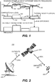
- Fig. 2 illustrates an exemplary Ka band satellite communication system 200.
- System 200 may include a satellite terminal 202, a satellite 204, and a satellite gateway 206.
- satellite gateway 206 measures signal quality and transmits a signal, including a SQI, to the respective sending satellite terminal 202.
- Fig. 2 shows satellite gateway 206 transmitting a signal, including the SQI, to satellite terminal 202 via outroute 210, satellite 204, and outroute 308 in response to satellite gateway 206 receiving a signal (not shown) from satellite terminal 202.
- Satellite terminal 202 may transmit a signal at a power level of P TX to satellite gateway 206 via a first inroute (not shown) of satellite 204, and a second inroute (not shown).
- the transmitted signal may experience path loss, or attenuation, before reaching satellite 204, and may experience path loss, or attenuation, when transmitted from satellite 204 to satellite gateway 206.
- Outroute transmissions from satellite gateway 206 to satellite terminal(s) 202 may cause interference with respect to inroute transmissions from one or more satellite terminals 202.
- Random additive noise, No may also cause a loss of signal strength with respect to transmissions from one or more satellite terminals.
- Fig. 3 shows sources of interference affecting a satellite terminal's inroute transmission.
- satellite terminal's inroute transmission 302 (as received at the satellite receive spatial beamformer) is interfered with by [co-channel, co-pol] transmissions from one or more other satellite gateways 308 and satellite terminals 310.
- the interference is mitigated by the spatial beamformer.
- Gain at the satellite receive spatial beamformer with respect to locations of interfering satellite gateway(s) 308 and satellite terminal(s) 310 is lower compared to gain at a location of satellite terminal 304. For example, gain from a return uplink from interfering satellite terminal(s) 310 and from a return uplink from interfering satellite gateway(s) 308 can be 10 dB weaker than the gain from the return uplink from desired satellite terminal 304.
- a return downlink to interfering gateway(s) 316 can be 10 dB weaker than the return downlink to desired satellite gateway 314. The difference in gain helps mitigate the co-channel interference (CCI).
- CCI co-channel interference
- FIG. 4 illustrates a special case of the more general interference characterization shown in FIG. 3 .
- the spectral densities of thermal noise and outroute interference in dBW/Hz are denoted, respectively, as N 0 dBW and I 0 dBW .
- I 0 dBW is typically several decibels below N 0 dBW .
- the composite N 0 dBW + I 0 dBW rises over the thermal noise floor.
- This Rise Over Thermal (ROT) creates hills, shown in FIG. 1 , wherever the outroute interference is present.
- ROT Rise Over Thermal
- satellite gateway 412 transmits on outroute 402 to satellite 410, which transmits to a satellite terminal in beam 19.
- Beam 34 of satellite 410 receives a signal of interest from a satellite terminal and transmits the signal of interest on a return downlink 404 to satellite gateway 414.
- Satellite gateway 416 transmits a signal on outroute 409 to satellite 410, which transmits the signal to a satellite terminal in beam 51.
- the signal of interest transmitted on a return downlink 404 from satellite 410 to satellite gateway 414 experiences interference 408, 406 from outroutes 402 and 409, respectively.
- C N 0 s c f k IR RX is a received inroute carrier to noise ratio (C/N 0 ) at the satellite gateway.
- P I+N (f, k) and G(f, k) denote the I+N floor and a return link gain G, respectively, which are taken as functions only of (frequency, frame number), and not of (s, c).
- P I + N f k P ULPC s c f k + G f k ⁇ C N 0 s c f k IR RX
- a satellite terminal A satellite terminal
- P ULPC R s c (s, c) is the terminal transmit power determined during the ranging
- P STF and P ULFE are the outputs of the STF and UpLink Fade Estimator (ULFE) filters, respectively
- h[°] represents a nonlinear function of the frequency (e.g., a Look-Up Table that converts the ULPC (STF + UL
- P ULPC (s, c, f, k) may be estimated by using applied ULPC attenuation.
- P ULPC s c f k P max ⁇ ⁇ ULPC s c f k
- P I+N (f, k) is averaged over time (multiple frames) to obtain an estimate of the interference plus noise floor P I+N (f) at frequency f; this averaging, or the Long Term Filtering (LTF), is performed only over those frames, say a total of N f frames, which are transmitted in the clear-sky conditions.
- P ⁇ I + N f LTF clear ⁇ sky
- P ⁇ I + N f k LTF clear ⁇ sky ⁇ ULPC adj s c f k
- ⁇ ULPC adj s c f k ⁇ ⁇ ULPC s c f k ⁇ C N 0 s c f k IR Target .
- FIG. 5 illustrates an exemplary design of uplink power control for an embodiment within a satellite terminal.
- the satellite terminal For measurement of the estimated differential I+N floor levels, ⁇ I+N (f), for different inroute frequencies, the satellite terminal maintains a bank of Long Term Filters (LTFs) 502 ( FIG. 5 ). Each LTF 502 corresponds to a different inroute frequency.
- LTFs Long Term Filters
- LTF 502 There is one LTF 502 for each inroute frequency starting from a low end of the available return link spectrum to an upper end of the spectrum.
- LTFs 502 may be initially assigned values from an Interference Compensation (IC) Table 504, which is received on a broadcast channel.
- IC Interference Compensation
- the satellite terminal selects an LTF, corresponding to the assigned IR frequency, from LTFs 502 (from the bank of LTFs).
- the selected LTF may be fed, as an input, either the output of the STF, the power control error (PCE), or the commanded attenuation.
- Fig. 5 shows PCE as the input to LTFs 502.
- an average of outputs of the selected LTF, relative to a reference LTF is averaged with appropriate entries in broadcast channel Interference Compensation (IC) Table 504.
- the reference LTF corresponds to the ranged frequency, which is a unique frequency (i.e., the terminal performs single-rate ranging on only one inroute frequency).
- the output of the reference LTF is used to adapt the ranging attenuation setting.
- a sum total of the LTF output, the outputs of the STF and the ULFE filters and a negative of the continuously adapted (using the reference LTF output) ranging attenuation determines the transmit power setting.
- a periodic multi-frequency ranging process may be used in a variation of this method. In the variation, the multi-frequency ranging process may be performed every 24 hours or another suitable time period.
- a ranging process may be performed on multiple frequencies on which the satellite terminal may transmit.
- satellite terminal 202 transmits an Aloha message on a ranged frequency, initially, at a maximum power level.
- Fig. 6 is a flowchart illustrating an exemplary process in which a satellite terminal performs the ranging process.
- the process may begin with the satellite terminal setting a transmit frequency, freq, transmit power, P TX , to maximum power, and a measurement threshold ⁇ (act 602).
- the satellite terminal may then transmit on inroute frequency, freq, at transmit power, P TX (act 604).
- a satellite gateway may then receive the signal on the satellite terminal's inroute at frequency, freq, and may measure a signal quality indicator (SQI) of the received signal (act 606).
- the satellite gateway may then send a signal including the measured SQI to the satellite terminal on an outroute (act 608).
- SQI signal quality indicator
- the satellite terminal may receive the signal including the measured SQI and may compare the SQI with a signal quality target (SQT) (act 610). Satellite terminal 202 may then determine whether the measured SQI converged to within a predetermined value, ⁇ , of the SQT (i.e.,
- P TX transmit power
- the satellite terminal may determine whether SQI is greater than SQT (act 616). If the satellite terminal determines that SQI is not greater than SQT, then satellite terminal 202 may adjust the measurement threshold ⁇ (act 618). Acts 602-612 may then be repeated.
- the satellite terminal may reduce the transmit power, P TX , by ⁇ (act 620). Acts 604-612 may then be repeated.
- the measurement threshold ⁇ and transmit power adjustment step size ⁇ may be adjusted appropriately to ensure that the ranging process converges, i.e.
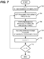
- Fig. 7 is a flowchart illustrating an exemplary process that may be performed by satellite 202 when ranging over multiple frequencies.
- the process may begin with the satellite terminal initializing a variable, n, to 1 and initializing a variable, N, to a maximum number of inroutes (act 702). Satellite terminal 202 may then set a transmission frequency to f(n) (act 704). Next, the satellite terminal may perform the ranging the process, illustrated by the flowchart of Fig. 6 , for the set transmission frequency (act 706). The ranged power, P TX-RANGED , may then be recorded for the set transmission frequency (act 708). The variable, n, may then be incremented (act 710). The satellite terminal may then determine whether n is greater than N (act 712). If n is determined not to be greater than N, then the satellite terminal may repeat acts 704-712. Otherwise, the satellite terminal may complete the process.
- FIG. 8 is a flowchart that illustrates an exemplary process for generation of an interference compensation (IC) table at the satellite gateway.
- P TX-RANGED ranged powers
- the satellite gateway may average the reported IC tables (P TX-RANGED (m, n)) from the reporting satellite terminals after accounting for terminal specific biases (act 810).
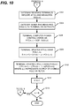
- Figs. 9 and 10 are flowcharts of an exemplary process for continuous interference compensation estimation at a satellite terminal using a bank of LTFs.
- the process may begin with the satellite terminal reading IC table (n), which is broadcast on an outroute by the satellite gateway (act 902).
- the satellite terminal may then initialize N LTFs, LTF(n,0), where LTF(n,0) is set to IC(n) (act 904).
- the satellite terminal may then initialize a system tracking filter, STF(0), to zero (act 906).
- the satellite terminal 202 then may determine a number, K, of frames required for an uplink session over an inroute (act 908).
- the satellite terminal then may receive an inroute assignment, index n, from the satellite gateway (act 910).
- the satellite terminal may then set transmit frequency, Freq, to f(n), and may set a frame number, k, to zero (act 912).
- the satellite terminal may set the transmit power, P TX (k), to P TX-RANGED + LTF(n,k) + STF(k) (act 914).
- the satellite terminal may then transmit a signal at power P TX (k) on inroute f(n) at frame k (act 916).
- the satellite gateway may then receive the transmitted signal from the satellite terminal on inroute f(n) and may measure SQI(n,k) (act 1002; FIG. 10 ). Satellite gateway 206 may then send the measured SQI(n,k) to the satellite terminal on the outroute (act 1004).
- IIR Infinite Impulse Response
- the variable K may then be incremented (act 1012) and if k is determined to be less than K, then acts 914-1014 may again be performed. Otherwise, if k is determined not to be less than K, the process may then be completed.
- Fig. 11 shows a simplified block diagram of a satellite terminal, which may be used in various embodiments.
- the exemplary satellite terminal includes a transmitter 1104 (modulator + IF and RF radio), a receiver 1106 (RF/IF Radio + demodulator) and a processing element 1102, which may include at least one of a general purpose processor, an Application Specific Integrated Circuit (ASIC), a Digital Signal Processor (DSP) or a Field Programmable Gate Array (FPGA).
- the interference compensation and power control algorithms may be executed by processing element 1102.
- Information packets along with a transmit power control word (PCW TX ) and an inroute frequency (fn) may be sent by processing element 1102 via an interface to transmitter 1104.
- Receiver 1106 receives an outroute carrier signal on an outroute, demodulates the outroute carrier signal to recover information packets, and sends the information packets to processing element 1102 over an interface.
- PCW TX transmit power control word
- fn inroute frequency
Description
- The invention relates to a method and a Ka band communication satellite system for compensating for an effect of co-channel and co/cross-polarization interference on satellite feeder and service links. More particularly, the invention relates to a method and a Ka band satellite communication system for simultaneous compensation of frequency flat and fast varying channel variations as well as frequency sensitive channel variations that vary slowly (i.e., are nearly static) over time.
- In certain Ka band satellite communication systems, satellite gateway outroute transmissions intended for one or more satellite terminals can interfere with inroute transmissions from satellite terminals to a satellite gateway. The inroute transmissions are affected by thermal noise effects with a spectral density of N0 Watts/Hz. The presence of outroute interference results in an increase in the spectral floor due to the undesired effects from No to No+Io (where Io refers to spectral density, or level, of outroute induced interference). The level, Io, of the interference can vary with varying center frequencies and bandwidths of the outroute signals (i.e., the interference floor Io as a function of the frequency can be uneven). Inroutes on certain transmission frequencies experience more interference compared to inroutes on some other transmission frequencies.
- In certain existing satellite communication systems, spectral density, or level, of noise plus interference No+Io is assumed to be identical across all frequencies. During initial installation and commissioning, the satellite terminal performs a procedure, subsequently referred to as a ranging procedure, to account for the No+Io level, in addition to a nominal value of end-to-end channel gain. The satellite terminal transmits the ranging signal at one frequency. Based on a received power level PRX, of the ranged frequency received at the satellite gateway, the satellite terminal determines a nominal transmit power level (the ranging power setting). The certain existing satellite communication systems assume that the spectral density, No+Io, is flat across all inroute frequencies. As a result, the nominal transmit power level estimated at the ranging frequency is used with respect to other inroute frequencies.
- During the ranging process, the satellite terminal transmits a ranging signal at a maximum power level. The satellite gateway receiver measures a signal quality of the ranging signal and the satellite gateway transmits a message to the satellite terminal containing a measured Signal Quality Indicator (SQI). The SQI, as received by the terminal, typically exceeds a Signal Quality Target (SQT). The satellite terminal subsequently reduces transmit power and retransmits the ranging signal. The ranging process is repeated until the SQI received by the terminal from the satellite gateway approximately equals the SQT. When this occurs, the ranging process is declared to have been converged, and the terminal stores the final transmitted power upon the convergence of the ranging power. When the ranging process is performed during a clear sky condition, the ranging power value is determined by a clear sky path loss, satellite and ground equipment hardware gains, and the noise and interference N0+I0 spectral density.
- Subsequent to ranging, when the satellite terminal initiates a transmission, the satellite terminal determines a power level with which to begin the transmission. The ranging power derived during an initial ranging process is a best estimate that the terminal has for the power level. The estimate is accurate during the clear sky condition and for an operating scenario in which the noise and interference (N0+I0) floor, or level, is flat (i.e., it does not exhibit variations over different inroute frequencies). It is with assumptions as described above that, in an existing Ka band system, the ranging power value derived by the satellite terminal is used as a nominal transmit power whenever the satellite terminal initiates a return uplink transmission subsequent to the ranging process.
- Similar to the ranging process, the satellite gateway continually measures the SQI for each uplink transmission from the satellite terminal and sends a message containing the SQI to the satellite terminal. The satellite terminal measures the difference between the SQT and the SQI received from the satellite gateway. The measured difference is a Power Control Error or PCE.
- The PCE is used as an input to a system tracking filter (STF). An output of the STF is used to adjust the transmit power of the satellite terminal, relative to the initial transmit power, which is equal to the ranging power level. A positive-valued PCE, which occurs when SQT exceeds SQI, indicates that the satellite terminal is under-powered (i.e., it is transmitting at a less than desired power level). The positive-valued PCE causes the STF output to increase, which, in turn, increases the satellite terminal transmit power. The increased satellite terminal transmit power reduces a shortfall of the SQI relative to the SQT. Similarly, a negative-valued PCE results in the satellite terminal reducing the transmit power. Thus, in general, the PCE and the STF act to balance the satellite terminal transmit power, such that it is just enough to ensure that SQI approximately equals SQT. One single STF is used across all the inroute frequencies. This is because of the assumption, stated earlier, that the N0+I0 floor is flat. With this assumption, the main variable in an end-to-end link is Ka band channel gain, which can decrease from its value during the clear sky condition. The STF compensates for variation of the channel gain.
-
U.S. Patent Application Publication No. 2009/117854 A1 of Davis et al. ("Davis") is related to link performance control in an enhanced bandwidth efficient modem for transponded satellite communication. See Davis at paragraph 0004. Davis discloses adapting the transmit power at a local transmitter in response to a sequence of intermittent signal quality reports from a remote receiver. Davis takes into account variations in accuracy and timeliness of the signal quality reports, variations in time latencies inherent in distributed processing and propagation path changes. - This Summary is provided to introduce a selection of concepts in a simplified form that is further described below in the Detailed Description. This Summary is not intended to identify key features or essential features of the claimed subject matter, nor is it intended to be used to limit the scope of the claimed subject matter. The scope of the invention is defined by the independent claims to which reference should now be made. Advantageous features are set out in the dependent claims.
- In a first aspect, a ranging process is performed to encompass multiple frequencies. As a result, a satellite terminal derives a multiplicity of ranging power settings, with each setting attuned to a corresponding frequency of the multiple frequencies. During the ranging process, channel gain variations typically do not change significantly across the multiple frequencies. Therefore, relative variations of the ranging power settings at multiple frequencies approximate variations in a noise and interference floor.
- In a second aspect, satellite terminals may periodically (e.g., once a day or once a week, etc.) perform a multi-frequency ranging process and report to a satellite gateway observed variations in the ranging power settings, based on received corresponding SQIs from the satellite gateway for each of the multiple frequencies. The observed variations are estimates of noise and interference levels formed at a given terminal. The satellite gateway may average the reported variations from the satellite terminals and may broadcast averaged values of the reported variations. The satellite terminals may use the broadcasted averaged values of the reported variations to update their ranging power settings.
- In a third aspect of the invention, a method is developed in which a satellite terminal continually tracks temporal variations in the noise and interference (N0+I0) floor. The tracking is performed by a filter, denoted as a Long Term Filter or LTF. Input of the LTF and its concept of operation are identical to that of the STF (described in paragraph [0007]). A main difference between the STF and the LTF is that the LTF has a larger inertia compared to the STF. While the STF is designed to quickly respond to a fast changing variation in the end-to-end channel gain, the LTF is designed to track relatively slower variations in N0+I0 floor, and therefore, is designed to have a much slower response to varying stimuli. Output of the LTF, therefore, ideally reflects the temporal variations in N0+I0 floor. Furthermore, while the STF is not associated with a specific inroute frequency (the same STF is used for all the frequencies), the terminal has one LTF per each inroute frequency.
- In order to describe the manner in which the above-recited and other advantages and features can be obtained, a more particular description is provided below and will be rendered by reference to specific embodiments thereof which are illustrated in the appended drawings. Understanding that these drawings depict only typical embodiments and are not therefore to be considered to be limiting of its scope, implementations will be escribed and explained with additional specificity and detail through the use of the accompanying drawings.
-
Fig. 1 illustrates noise and interference levels at various frequencies and their effect on power levels of signals received at a satellite gateway. -
Fig. 2 illustrates an exemplary Ka band satellite communication system in which a satellite gateway transmits a SQI corresponding to a signal transmitted by a satellite terminal. -
Figs. 3 and 4 illustrate exemplary Ka band satellite communication systems showing sources of interference. -
Fig. 5 is an exemplary design of uplink power control interference compensation for a satellite terminal. -
Fig. 6 is a flowchart of an exemplary process for a satellite terminal to perform a ranging process in an embodiment of the invention. -
Fig. 7 is a flowchart illustrating an exemplary process that may be performed by a satellite terminal to perform a multi-frequency ranging process. -
Fig. 8 is a flowchart illustrating an exemplary process for generating an interference compensation table for a satellite gateway. -
Figs. 9 and10 are flowcharts illustrating an exemplary process for a satellite terminal to continuously estimate interference compensation. -
Fig. 11 illustrates an exemplary hardware configuration for an embodiment. - Embodiments are discussed in detail below. While specific implementations are discussed, it should be understood that this is done for illustration purposes only. A person skilled in the relevant art will recognize that other components and configurations may be used without parting from the scope of the subject matter of this disclosure.
- A method and a Ka band satellite system are provided for compensating for inroute interference. More particularly, the invention relates to a method and a Ka band satellite communication system for simultaneous compensation of frequency flat and fast varying channel variations as well as frequency sensitive channel variations that vary slowly (nearly static) over time. A level of the nearly static frequency sensitive channel variations differs from one transmission frequency to another. The fast varying channel variations may arise, for example, because path loss variations at Ka band are rapid during rain events. Similarly, on each transmission frequency several co-channel interference sources and co/cross-polarization interference sources change quickly (they arise and subside as new terminals become active or currently active terminals become inactive).
- When a satellite terminal of a Ka band satellite system is installed, ranging is performed over multiple frequencies. During the ranging, a signal is transmitted, initially, at a maximum power level on each of the multiple frequencies. When a satellite gateway receives the signal, the satellite gateway measures received signal quality and sends an indicator of the received signal quality, i.e., the signal quality indicator (SQI), to the satellite terminal on the outroute. The satellite terminal, upon receiving the SQI, compares the SQI against a signal quality target (SQT) and adjusts a transmission power level according to a difference between the SQI and the SQT. The satellite terminal retransmits the ranging signal after adjusting the transmission power. The process is repeated until the SQI converges to the SQT (i.e., is within a predefined tolerance of the SQT). When the SQI converges, the satellite terminal determines the ranged power setting at a respective frequency as a final value of the ranging power for the respective frequency. The ranging process is repeated on each inroute frequency. The satellite terminal derives a vector of ranged power setting values at completion of the multi-frequency ranging process. Each value in the vector corresponds to the ranged power setting at a respective particular inroute frequency.
- The satellite terminal may perform the multi-frequency ranging process periodically, and send the measured vector of ranged power setting values to the satellite gateway. The satellite gateway may normalize the vector with respect to a reference inroute frequency. The normalized vector represents an estimate of noise and interference N0+I0 across different frequencies. In some embodiments, the satellite gateway averages multiple vectors received from different terminals and broadcasts the averaged normalized vector as an estimate of noise and interference N0+I0 on the outroute.
- During transmissions subsequent to the initial ranging process, the satellite terminal, in various embodiments, continually updates a power control error or PCE, which is a difference between the SQT and the SQI. The PCE is passed through two filters. One filter is a system tracking filter or STF. The STF has a fast response and is intended to track fast changing interference variations (e.g., due to weather events) in channel gain. The second filter is called a long term filter or LTF. One LTF is maintained per each inroute frequency (i.e., the LTF is a bank of filters). The LTF may be initialized with an estimate of a noise and interference N0+I0 level broadcast by the satellite gateway on the outroute. Output of the LTF tracks the slow changing interference variations of the N0+I0 level per frequency.
- A return link, or inroute N0+I0 level variation as a function of frequency is mainly due to interference caused by the satellite gateway's outroute transmission. A conceptual model shown
Fig. 1 assumes that all the inroutes are at an identical (symbol, code) rate pair, i.e., they have the same Target ES/N0. A receivedpower level 102 at the satellite gateway for the different inroutes, as a function of inroute frequency, varies in a manner identical to the N0+I0floor variation valleys 104 andpedestals 106 in N0+I0 floor leads tovalleys 108 andpedestals 110 in the power received at the satellite gateway for the different inroutes. -
Fig. 2 illustrates an exemplary Ka bandsatellite communication system 200.System 200 may include asatellite terminal 202, asatellite 204, and asatellite gateway 206. For each received transmission from a respective sendingsatellite terminal 202,satellite gateway 206 measures signal quality and transmits a signal, including a SQI, to the respective sendingsatellite terminal 202.Fig. 2 showssatellite gateway 206 transmitting a signal, including the SQI, tosatellite terminal 202 viaoutroute 210,satellite 204, andoutroute 308 in response tosatellite gateway 206 receiving a signal (not shown) fromsatellite terminal 202. -
Satellite terminal 202 may transmit a signal at a power level of PTX tosatellite gateway 206 via a first inroute (not shown) ofsatellite 204, and a second inroute (not shown). The transmitted signal may experience path loss, or attenuation, before reachingsatellite 204, and may experience path loss, or attenuation, when transmitted fromsatellite 204 tosatellite gateway 206. Outroute transmissions fromsatellite gateway 206 to satellite terminal(s) 202 may cause interference with respect to inroute transmissions from one ormore satellite terminals 202. Random additive noise, No, may also cause a loss of signal strength with respect to transmissions from one or more satellite terminals. -
Fig. 3 shows sources of interference affecting a satellite terminal's inroute transmission. On areturn uplink 302 from asatellite terminal 304 to asatellite 306, satellite terminal's inroute transmission 302 (as received at the satellite receive spatial beamformer) is interfered with by [co-channel, co-pol] transmissions from one or moreother satellite gateways 308 andsatellite terminals 310. The interference is mitigated by the spatial beamformer. Gain at the satellite receive spatial beamformer with respect to locations of interfering satellite gateway(s) 308 and satellite terminal(s) 310 is lower compared to gain at a location ofsatellite terminal 304. For example, gain from a return uplink from interfering satellite terminal(s) 310 and from a return uplink from interfering satellite gateway(s) 308 can be 10 dB weaker than the gain from the return uplink from desiredsatellite terminal 304. - On a
return downlink 312 fromsatellite 306 tosatellite gateway 314, an inroute transmission from satellite terminal 304 (as transmitted by the satellite transmit beamformer) is interfered with by [co-channel, co-pol] transmission to one or moreother satellite gateways 316 and one or moreother satellite terminals 318. The beam over a targeted location ofsatellite gateway 314 has a higher gain compared to side lobes of satellite transmit beams towards interfering satellite gateway(s) 316 and interfering satellite terminal(s) 318. For example, a return downlink to interfering gateway(s) 316 can be 10 dB weaker than the return downlink to desiredsatellite gateway 314. The difference in gain helps mitigate the co-channel interference (CCI). - Thus, there are three sources of interference for a return link inroute transmission from a satellite terminal: (i) outroute transmissions by different co-channel, co-pol satellite gateways, (ii) inroute transmissions from other co-channel, co-pol satellite terminals, and (iii) transmissions from neighboring satellite systems.
-
FIG. 4 illustrates a special case of the more general interference characterization shown inFIG. 3 . Suppose the spectral densities of thermal noise and outroute interference in dBW/Hz are denoted, respectively, as

FIG. 1 ,


composite 
FIG. 1 , wherever the outroute interference is present. - As shown in
FIG. 4 ,satellite gateway 412 transmits onoutroute 402 tosatellite 410, which transmits to a satellite terminal inbeam 19. Beam 34 ofsatellite 410 receives a signal of interest from a satellite terminal and transmits the signal of interest on areturn downlink 404 tosatellite gateway 414.Satellite gateway 416 transmits a signal onoutroute 409 tosatellite 410, which transmits the signal to a satellite terminal inbeam 51. The signal of interest transmitted on areturn downlink 404 fromsatellite 410 tosatellite gateway 414experiences interference outroutes - A method is described for estimating a differential Interference and Noise (I+N) floor, which is defined as follows:

- Uplink Power Control (ULPC) transmit power, PULPC(s, c, f, k), at (symbol rate s, code rate c, frequency f, frame number k) is as follows:

- Here,

- From Eq. 2, a noise and interference floor at (frequency = f, frame number = k) is as follows.

- A satellite terminal
- knows

- ∘ Alternatively, to avoid a measurement error in estimation of


- ∘ Alternatively, to avoid a measurement error in estimation of
- Does not have a measurement of PULPC (s, c, f, k).
- Does not have a direct measurement of uplink [frequency, frame number] dependent gain term G(f, k).
- In a method of uplink power control, transmit power PULPC (s, c, f, k) is written as follows:


- PULPC(s, c, f, k) may be estimated by using applied ULPC attenuation.

- Here, an exact value of a maximum satellite terminal transmit power Pmax is neither known nor required (the latter since Pmax is assumed to be independent of the frequency and thus, is canceled out in the calculation of ΔI+N(f) in Eq. 1). The term αULPC(s, c, f, k) denotes attenuation relative to Pmax applied by the ULPC.
- The following indicates the estimate of PI+N(f, k).

- Thus, in this method, the unknown return gain term G(f, k) is replaced by a constant g' dB. A rationale behind this assumption is that the long-term averaging is used only in the clear-sky condition, during which G(f, k) ≈ g' dB.
- Estimated PI+N(f, k) is averaged over time (multiple frames) to obtain an estimate of the interference plus noise floor PI+N(f) at frequency f; this averaging, or the Long Term Filtering (LTF), is performed only over those frames, say a total of Nf frames, which are transmitted in the clear-sky conditions.

- Here,

- The parameter of interest, ΔI+N(f) in Eq. 1, is estimated as follows:

-
FIG. 5 illustrates an exemplary design of uplink power control for an embodiment within a satellite terminal. For measurement of the estimated differential I+N floor levels, Δ̂I+N(f), for different inroute frequencies, the satellite terminal maintains a bank of Long Term Filters (LTFs) 502 (FIG. 5 ). EachLTF 502 corresponds to a different inroute frequency. - There is one
LTF 502 for each inroute frequency starting from a low end of the available return link spectrum to an upper end of the spectrum.LTFs 502 may be initially assigned values from an Interference Compensation (IC) Table 504, which is received on a broadcast channel. Subsequent to a successful ALOHA attempt and after receiving an inroute channel assignment, the satellite terminal selects an LTF, corresponding to the assigned IR frequency, from LTFs 502 (from the bank of LTFs). The selected LTF may be fed, as an input, either the output of the STF, the power control error (PCE), or the commanded attenuation.Fig. 5 shows PCE as the input toLTFs 502. - At each power control loop update, an average of outputs of the selected LTF, relative to a reference LTF, is averaged with appropriate entries in broadcast channel Interference Compensation (IC) Table 504. The reference LTF corresponds to the ranged frequency, which is a unique frequency (i.e., the terminal performs single-rate ranging on only one inroute frequency). The output of the reference LTF is used to adapt the ranging attenuation setting. A sum total of the LTF output, the outputs of the STF and the ULFE filters and a negative of the continuously adapted (using the reference LTF output) ranging attenuation determines the transmit power setting. A periodic multi-frequency ranging process may be used in a variation of this method. In the variation, the multi-frequency ranging process may be performed every 24 hours or another suitable time period.
- When a satellite terminal is installed, a ranging process may be performed on multiple frequencies on which the satellite terminal may transmit. During the ranging process,
satellite terminal 202 transmits an Aloha message on a ranged frequency, initially, at a maximum power level. -
Fig. 6 is a flowchart illustrating an exemplary process in which a satellite terminal performs the ranging process. The process may begin with the satellite terminal setting a transmit frequency, freq, transmit power, PTX, to maximum power, and a measurement threshold ε (act 602). The satellite terminal may then transmit on inroute frequency, freq, at transmit power, PTX (act 604). A satellite gateway may then receive the signal on the satellite terminal's inroute at frequency, freq, and may measure a signal quality indicator (SQI) of the received signal (act 606). The satellite gateway may then send a signal including the measured SQI to the satellite terminal on an outroute (act 608). The satellite terminal may receive the signal including the measured SQI and may compare the SQI with a signal quality target (SQT) (act 610).Satellite terminal 202 may then determine whether the measured SQI converged to within a predetermined value, ε, of the SQT (i.e., |SCT - SQI| ≤ ε) (act 612). If the satellite terminal determines that the SQI has converged to within ε of the SQT, then the satellite terminal may record a current value of the transmit power, PTX, as a ranging power, PTX-Ranged, associated with frequency, freq, (act 614) and the process may be completed. - If, during
act 612, the satellite terminal determines that the SQI has not yet converged, then the satellite terminal may determine whether SQI is greater than SQT (act 616). If the satellite terminal determines that SQI is not greater than SQT, thensatellite terminal 202 may adjust the measurement threshold ε (act 618). Acts 602-612 may then be repeated. - If, during
act 616, the satellite terminal determines that SQI is greater than SQT, then the satellite terminal may reduce the transmit power, PTX, by δ (act 620). Acts 604-612 may then be repeated. - Note that the measurement threshold ε and transmit power adjustment step size δ may be adjusted appropriately to ensure that the ranging process converges, i.e. |SQT - SQI| ≤ ε, after several iterations of the feedback process shown in
Fig. 6 . -
Fig. 7 is a flowchart illustrating an exemplary process that may be performed bysatellite 202 when ranging over multiple frequencies. The process may begin with the satellite terminal initializing a variable, n, to 1 and initializing a variable, N, to a maximum number of inroutes (act 702).Satellite terminal 202 may then set a transmission frequency to f(n) (act 704). Next, the satellite terminal may perform the ranging the process, illustrated by the flowchart ofFig. 6 , for the set transmission frequency (act 706). The ranged power, PTX-RANGED, may then be recorded for the set transmission frequency (act 708). The variable, n, may then be incremented (act 710). The satellite terminal may then determine whether n is greater than N (act 712). If n is determined not to be greater than N, then the satellite terminal may repeat acts 704-712. Otherwise, the satellite terminal may complete the process. -
FIG. 8 is a flowchart that illustrates an exemplary process for generation of an interference compensation (IC) table at the satellite gateway. The process may begin with the satellite gateway initializing variables m to 1, N to maximum number of inroutes, and M to number of terminals (act 802). After ranging over multiple frequencies, satellite terminal m reports to the satellite gateway a table of recorded ranged powers (PTX-RANGED(m, n)) for all inroute frequencies f(n), where n = 1, 2, ... N (act 804). The satellite gateway may then increment the variable, m, (act 806) and may determine whether m is greater than M (act 808). If m is determined not to be greater than M, then the satellite gateway may repeat acts 804-808. Otherwise, the satellite gateway may average the reported IC tables (PTX-RANGED(m, n)) from the reporting satellite terminals after accounting for terminal specific biases (act 810). The satellite gateway may then generate an averaged IC table (IC(n)), for n = 1, ..., N, and may broadcast the IC table to the reporting satellite terminals on an outroute (act 812). The process may then be completed. -
Figs. 9 and10 are flowcharts of an exemplary process for continuous interference compensation estimation at a satellite terminal using a bank of LTFs. The process may begin with the satellite terminal reading IC table (n), which is broadcast on an outroute by the satellite gateway (act 902). The satellite terminal may then initialize N LTFs, LTF(n,0), where LTF(n,0) is set to IC(n) (act 904). The satellite terminal may then initialize a system tracking filter, STF(0), to zero (act 906). Thesatellite terminal 202 then may determine a number, K, of frames required for an uplink session over an inroute (act 908). The satellite terminal then may receive an inroute assignment, index n, from the satellite gateway (act 910). The satellite terminal may then set transmit frequency, Freq, to f(n), and may set a frame number, k, to zero (act 912). At frame k, the satellite terminal may set the transmit power, PTX(k), to PTX-RANGED + LTF(n,k) + STF(k) (act 914). The satellite terminal may then transmit a signal at power PTX(k) on inroute f(n) at frame k (act 916). The satellite gateway may then receive the transmitted signal from the satellite terminal on inroute f(n) and may measure SQI(n,k) (act 1002;FIG. 10 ).Satellite gateway 206 may then send the measured SQI(n,k) to the satellite terminal on the outroute (act 1004). The satellite terminal may then compute PCE, such that PCE(n,k) = SQT - SQI(n,k) (act 1006). The satellite terminal may then update STF(k) using PCE(n,k), such that STF(k+1) = STF(k) + α ∗ PCE(n,k), where α is a time constant of a first order Infinite Impulse Response (IIR) filter, which is typically << 1 (act 1008). The satellite terminal may then update LTF(n,k) using PCE(n,k) such that LTF(n,k+1) = LTF(n,k) + β ∗ ϕ{PCE(n, k)}, where ϕ{} represents output of a single pole Infinite Impulse Response (IIR) filter (act 1010). The variable K may then be incremented (act 1012) and if k is determined to be less than K, then acts 914-1014 may again be performed. Otherwise, if k is determined not to be less than K, the process may then be completed. -
Fig. 11 shows a simplified block diagram of a satellite terminal, which may be used in various embodiments. The exemplary satellite terminal includes a transmitter 1104 (modulator + IF and RF radio), a receiver 1106 (RF/IF Radio + demodulator) and aprocessing element 1102, which may include at least one of a general purpose processor, an Application Specific Integrated Circuit (ASIC), a Digital Signal Processor (DSP) or a Field Programmable Gate Array (FPGA). The interference compensation and power control algorithms may be executed byprocessing element 1102. Information packets along with a transmit power control word (PCWTX) and an inroute frequency (fn) may be sent byprocessing element 1102 via an interface totransmitter 1104.Receiver 1106 receives an outroute carrier signal on an outroute, demodulates the outroute carrier signal to recover information packets, and sends the information packets toprocessing element 1102 over an interface. - Although the subject matter has been described in language specific to structural features and/or methodological acts, it is to be understood that the subject matter in the appended claims is not necessarily limited to the specific features or acts described above. Rather, the specific features and acts described above are disclosed as example forms for implementing the claims.
- Although the above descriptions may contain specific details, they should not be construed as limiting the claims in any way. Other configurations of the described embodiments are part of the scope of this disclosure. Further, implementations consistent with the subject matter of this disclosure may have more or fewer acts than as described, or may implement acts in a different order than as shown. Accordingly, the appended claims
should only define the invention, rather than any specific examples given.
Claims (12)
- A method performed by a satellite terminal for compensating for noise and interference in a Ka band satellite system, the method comprising:
for each respective frequency of a plurality of frequencies, performing a ranging process (702, 704, 706, 710, 712) comprising:transmitting a ranging signal over the respective frequency from the satellite terminal (604);receiving, at the satellite terminal from a satellite gateway, a signal quality indicator in response to the transmitting the ranging signal over the respective frequency (608);adjusting a transmit power on the respective frequency at the satellite terminal based on a difference between the signal quality indicator and a signal quality target (612, 616, 620);repeating the transmitting of the ranging signal (604), the receiving of the signal quality indicator (608), and the adjusting of the transmit power (620) until the difference between the received signal quality indicator and the signal quality target is within a predefined tolerance (612); andstoring a value representing the adjusted transmission power as a ranged power setting at the respective frequency in a vector of ranged power settings for the plurality of frequencies when the difference between the received signal quality indicator and the signal quality target is within the predefined tolerance (612, 614);performing, after the ranging process for each of the respective frequencies is completed, the steps of:setting a new transmit power for transmitting a frame on one of the plurality of frequencies, the new transmit power being determined based on the ranged power setting for the one of the plurality of frequencies, a value of a long term filter for the one of the plurality of frequencies, and a value of a system tracking filter, the long term filter tracking slow changing variations in a noise plus interference floor for the one of the plurality of frequencies and the system tracking filter tracking fast changing variations in end-to-end channel gain (914), andtransmitting the frame on the one of the plurality of frequencies at the new transmit power (916). - The method of claim 1, further comprising:
receiving an inroute assignment from the satellite gateway before the setting the new transmit power for the frame on the one of the plurality of frequencies, the inroute assignment being associated with the one of the plurality of frequencies. - The method of claim 1, further comprising:sending, upon the completion of the ranging process, the vector of ranged power settings for each of the plurality of frequencies to the satellite gateway (804, 806, 808);receiving an averaged normalized vector of ranged power settings, the averaged normalized vector being based on vectors of ranged power settings from a plurality of satellite terminals (810, 812, 902); andupdating the vector of ranged power settings based on the received averaged and normalized vector of ranged power settings (902).
- The method of claim 1, further comprising:
updating the system tracking filter based on a difference between a signal quality indicator received by the satellite terminal from the satellite gateway during subsequent transmissions after the completion of the ranging process and the signal quality target (1008). - The method of claim 4, further comprising updating the long term filter for the one of the plurality of frequencies only during a clear-sky condition based on the difference between the signal quality indicator received by the satellite terminal from the satellite gateway during the subsequent transmissions after the completion of the ranging process and the signal quality target (1008).
- The method of claim 5, further comprising maintaining, by the satellite terminal, a current clear sky condition by continually monitoring the received signal quality indicator.
- The method of claim 4, further comprising compensating for the fast changing variations in the end-to-end channel gain by setting the transmit power level for transmitting on any of the plurality of frequencies based on a value of the system tracking filter, which is common across the plurality of frequencies (914).
- The method of claim 1, wherein the transmitting the ranging signal over the respective frequency from the satellite terminal further comprises transmitting an Aloha signal on the respective frequency initially at a maximum power level.
- The method of claim 1, wherein:the ranging process for the plurality of frequencies is periodically performed, andthe method further comprising:updating the long term filter for the one of the plurality of frequencies based on a difference between a signal quality indicator received by the satellite terminal from the satellite gateway during subsequent transmissions on the one of the plurality of frequencies after the completion of the ranging process and the signal quality target (1010), andadjusting the transmit power for a next subsequent transmission on the one of the plurality of frequencies after the completion of the ranging process based on the long term filter for the one of the plurality of frequencies updated after a last subsequent transmission on the one of the plurality of frequencies after the completion of the ranging process (914).
- The method of claim 9, wherein the ranging process further comprises:
transmitting an Aloha signal on each of the plurality of frequencies initially at a maximum power level. - The method of claim 9, further comprising:sending, upon the completion of the ranging process, the vector of ranged power settings for each of the plurality of frequencies to the satellite gateway (804);receiving an averaged normalized vector of final ranged power settings, the averaged normalized vector being based on vectors of ranged power settings from a plurality of satellite terminals (902); andupdating the vector of ranged power settings of the satellite terminal based on the received averaged normalized vector of ranged power settings (904).
- The method of claim 11, further comprising;
initializing the system tracking filter to zero (906).
Applications Claiming Priority (2)
| Application Number | Priority Date | Filing Date | Title |
|---|---|---|---|
| US14/681,470 US9578646B2 (en) | 2015-04-08 | 2015-04-08 | Interference compensation in uplink power control |
| PCT/US2016/026521 WO2016164639A1 (en) | 2015-04-08 | 2016-04-07 | Interference compensation in uplink power control |
Publications (2)
| Publication Number | Publication Date |
|---|---|
| EP3281307A1 EP3281307A1 (en) | 2018-02-14 |
| EP3281307B1 true EP3281307B1 (en) | 2020-10-14 |
Family
ID=55919891
Family Applications (1)
| Application Number | Title | Priority Date | Filing Date |
|---|---|---|---|
| EP16721022.8A Active EP3281307B1 (en) | 2015-04-08 | 2016-04-07 | Interference compensation in uplink power control |
Country Status (3)
| Country | Link |
|---|---|
| US (1) | US9578646B2 (en) |
| EP (1) | EP3281307B1 (en) |
| WO (1) | WO2016164639A1 (en) |
Families Citing this family (10)
| Publication number | Priority date | Publication date | Assignee | Title |
|---|---|---|---|---|
| US10200885B2 (en) * | 2016-05-12 | 2019-02-05 | Hughes Networks Systems, Llc | Satellite communication ranging |
| US10298315B2 (en) * | 2017-06-30 | 2019-05-21 | Hughes Network Systems, Llc | Interference level variation mitigation for satellite communicaton systems |
| US10651928B2 (en) * | 2017-12-20 | 2020-05-12 | Hughes Network Systems, Llc | System and method of adaptive interference avoidance in multi-beam satellite communications network |
| US11419064B2 (en) * | 2019-04-29 | 2022-08-16 | Hughes Network Systems, Llc | Gateway managed terminal uplink power control |
| US11700581B2 (en) * | 2019-05-03 | 2023-07-11 | Hughes Network Systems, Llc | Transmit frequency based terminal uplink power control in a satellite communication system |
| US11172454B2 (en) * | 2020-04-10 | 2021-11-09 | Totum Labs, Inc. | System and method for a power control scheme that optimizes downlink (DL) capacity |
| US11265076B2 (en) * | 2020-04-10 | 2022-03-01 | Totum Labs, Inc. | System and method for forward error correcting across multiple satellites |
| US11277199B1 (en) | 2020-10-29 | 2022-03-15 | Hughes Network Systems, Llc | Power control for frequency variation and gateway switching |
| US11632150B2 (en) * | 2021-04-01 | 2023-04-18 | Hughes Network Systems | Weather-resilient countermeasures for line-of-sight multiple-input multiple-output feeder links in multibeam satellite systems |
| CN113452433B (en) * | 2021-07-20 | 2022-10-11 | 中国人民解放军军事科学院国防科技创新研究院 | Low-orbit communication constellation inter-satellite transmission power control method |
Family Cites Families (4)
| Publication number | Priority date | Publication date | Assignee | Title |
|---|---|---|---|---|
| US5924015A (en) | 1996-04-30 | 1999-07-13 | Trw Inc | Power control method and apparatus for satellite based telecommunications system |
| US20090117854A1 (en) | 2007-11-02 | 2009-05-07 | Viasat, Inc. | Method and system for automatic uplink power control in wireless communication |
| US8576118B2 (en) * | 2008-01-29 | 2013-11-05 | Viasat, Inc. | Satellite performance monitoring |
| US8547863B2 (en) | 2009-07-08 | 2013-10-01 | Viasat, Inc. | MF-TDMA satellite link power control |
-
2015
- 2015-04-08 US US14/681,470 patent/US9578646B2/en active Active
-
2016
- 2016-04-07 EP EP16721022.8A patent/EP3281307B1/en active Active
- 2016-04-07 WO PCT/US2016/026521 patent/WO2016164639A1/en unknown
Non-Patent Citations (1)
| Title |
|---|
| None * |
Also Published As
| Publication number | Publication date |
|---|---|
| WO2016164639A1 (en) | 2016-10-13 |
| US20160302207A1 (en) | 2016-10-13 |
| US9578646B2 (en) | 2017-02-21 |
| EP3281307A1 (en) | 2018-02-14 |
Similar Documents
| Publication | Publication Date | Title |
|---|---|---|
| EP3281307B1 (en) | Interference compensation in uplink power control | |
| KR101287219B1 (en) | Power control method for up-link in mobile communication and apparatus thereof | |
| EP2282420B1 (en) | MF-TDMA Satellite Link Power Control | |
| US8576118B2 (en) | Satellite performance monitoring | |
| EP1771954B1 (en) | Leader-follower power control | |
| US8862051B2 (en) | Determining the repeater gain in dependence of interference | |
| US9912401B2 (en) | Adaptive fade mitigation | |
| IL127336A (en) | Methods and apparatus for controlling earth-station transmitted power in a vsat network | |
| EP2792202B1 (en) | Method for configuring a communication channel | |
| US20150270891A1 (en) | Uplink Power Control Method and Apparatus for Satellite Communications Networks | |
| EP2250739B1 (en) | Wireless communication power control | |
| US9402235B2 (en) | Non-cooperative power control for large-scale antenna systems | |
| JP2002043996A (en) | Method and apparatus for controlling transmission power threshold in satellite communication system | |
| Cioni et al. | Adaptive coding and modulation for the reverse link of broadband satellite networks | |
| US8634778B1 (en) | Carrier-in-carrier based performance optimization systems and related methods | |
| Andrenacci et al. | Exploiting orthogonality in DVB-S2X through timing pre-compensation | |
| US10305575B2 (en) | Mobile telecommunication repeater for canceling feedback signals | |
| Rafiqul et al. | Frequency diversity improvement factor for rain fade mitigation in Malaysia | |
| US8094606B1 (en) | Adjusting transmission power under changing conditions | |
| JP4017594B2 (en) | Satellite uplink power control | |
| Wang et al. | Terminal transmit adaptation for optimal link availability | |
| US20160095073A1 (en) | Inroute automatic gain control detection of outroute interference |
Legal Events
| Date | Code | Title | Description |
|---|---|---|---|
| STAA | Information on the status of an ep patent application or granted ep patent |
Free format text: STATUS: THE INTERNATIONAL PUBLICATION HAS BEEN MADE |
|
| PUAI | Public reference made under article 153(3) epc to a published international application that has entered the european phase |
Free format text: ORIGINAL CODE: 0009012 |
|
| STAA | Information on the status of an ep patent application or granted ep patent |
Free format text: STATUS: REQUEST FOR EXAMINATION WAS MADE |
|
| 17P | Request for examination filed |
Effective date: 20171108 |
|
| AK | Designated contracting states |
Kind code of ref document: A1 Designated state(s): AL AT BE BG CH CY CZ DE DK EE ES FI FR GB GR HR HU IE IS IT LI LT LU LV MC MK MT NL NO PL PT RO RS SE SI SK SM TR |
|
| AX | Request for extension of the european patent |
Extension state: BA ME |
|
| DAV | Request for validation of the european patent (deleted) | ||
| DAX | Request for extension of the european patent (deleted) | ||
| STAA | Information on the status of an ep patent application or granted ep patent |
Free format text: STATUS: EXAMINATION IS IN PROGRESS |
|
| 17Q | First examination report despatched |
Effective date: 20190104 |
|
| REG | Reference to a national code |
Ref country code: DE Ref legal event code: R079 Ref document number: 602016045794 Country of ref document: DE Free format text: PREVIOUS MAIN CLASS: H04B0007185000 Ipc: H04W0052500000 |
|
| RIC1 | Information provided on ipc code assigned before grant |
Ipc: H04W 52/50 20090101AFI20190514BHEP Ipc: H04B 7/185 20060101ALI20190514BHEP Ipc: H04W 72/04 20090101ALI20190514BHEP Ipc: H04W 72/08 20090101ALI20190514BHEP Ipc: H04W 52/24 20090101ALI20190514BHEP |
|
| GRAP | Despatch of communication of intention to grant a patent |
Free format text: ORIGINAL CODE: EPIDOSNIGR1 |
|
| STAA | Information on the status of an ep patent application or granted ep patent |
Free format text: STATUS: GRANT OF PATENT IS INTENDED |
|
| GRAJ | Information related to disapproval of communication of intention to grant by the applicant or resumption of examination proceedings by the epo deleted |
Free format text: ORIGINAL CODE: EPIDOSDIGR1 |
|
| GRAJ | Information related to disapproval of communication of intention to grant by the applicant or resumption of examination proceedings by the epo deleted |
Free format text: ORIGINAL CODE: EPIDOSDIGR1 |
|
| GRAP | Despatch of communication of intention to grant a patent |
Free format text: ORIGINAL CODE: EPIDOSNIGR1 |
|
| STAA | Information on the status of an ep patent application or granted ep patent |
Free format text: STATUS: EXAMINATION IS IN PROGRESS |
|
| GRAP | Despatch of communication of intention to grant a patent |
Free format text: ORIGINAL CODE: EPIDOSNIGR1 |
|
| STAA | Information on the status of an ep patent application or granted ep patent |
Free format text: STATUS: GRANT OF PATENT IS INTENDED |
|
| INTG | Intention to grant announced |
Effective date: 20191113 |
|
| INTC | Intention to grant announced (deleted) | ||
| INTG | Intention to grant announced |
Effective date: 20191210 |
|
| GRAS | Grant fee paid |
Free format text: ORIGINAL CODE: EPIDOSNIGR3 |
|
| GRAA | (expected) grant |
Free format text: ORIGINAL CODE: 0009210 |
|
| STAA | Information on the status of an ep patent application or granted ep patent |
Free format text: STATUS: THE PATENT HAS BEEN GRANTED |
|
| AK | Designated contracting states |
Kind code of ref document: B1 Designated state(s): AL AT BE BG CH CY CZ DE DK EE ES FI FR GB GR HR HU IE IS IT LI LT LU LV MC MK MT NL NO PL PT RO RS SE SI SK SM TR |
|
| REG | Reference to a national code |
Ref country code: GB Ref legal event code: FG4D |
|
| REG | Reference to a national code |
Ref country code: AT Ref legal event code: REF Ref document number: 1324808 Country of ref document: AT Kind code of ref document: T Effective date: 20201015 Ref country code: CH Ref legal event code: EP |
|
| REG | Reference to a national code |
Ref country code: DE Ref legal event code: R096 Ref document number: 602016045794 Country of ref document: DE |
|
| REG | Reference to a national code |
Ref country code: IE Ref legal event code: FG4D |
|
| REG | Reference to a national code |
Ref country code: AT Ref legal event code: MK05 Ref document number: 1324808 Country of ref document: AT Kind code of ref document: T Effective date: 20201014 |
|
| REG | Reference to a national code |
Ref country code: NL Ref legal event code: MP Effective date: 20201014 |
|
| PG25 | Lapsed in a contracting state [announced via postgrant information from national office to epo] |
Ref country code: GR Free format text: LAPSE BECAUSE OF FAILURE TO SUBMIT A TRANSLATION OF THE DESCRIPTION OR TO PAY THE FEE WITHIN THE PRESCRIBED TIME-LIMIT Effective date: 20210115 Ref country code: FI Free format text: LAPSE BECAUSE OF FAILURE TO SUBMIT A TRANSLATION OF THE DESCRIPTION OR TO PAY THE FEE WITHIN THE PRESCRIBED TIME-LIMIT Effective date: 20201014 Ref country code: PT Free format text: LAPSE BECAUSE OF FAILURE TO SUBMIT A TRANSLATION OF THE DESCRIPTION OR TO PAY THE FEE WITHIN THE PRESCRIBED TIME-LIMIT Effective date: 20210215 Ref country code: RS Free format text: LAPSE BECAUSE OF FAILURE TO SUBMIT A TRANSLATION OF THE DESCRIPTION OR TO PAY THE FEE WITHIN THE PRESCRIBED TIME-LIMIT Effective date: 20201014 Ref country code: NL Free format text: LAPSE BECAUSE OF FAILURE TO SUBMIT A TRANSLATION OF THE DESCRIPTION OR TO PAY THE FEE WITHIN THE PRESCRIBED TIME-LIMIT Effective date: 20201014 Ref country code: NO Free format text: LAPSE BECAUSE OF FAILURE TO SUBMIT A TRANSLATION OF THE DESCRIPTION OR TO PAY THE FEE WITHIN THE PRESCRIBED TIME-LIMIT Effective date: 20210114 |
|
| REG | Reference to a national code |
Ref country code: LT Ref legal event code: MG4D |
|
| PG25 | Lapsed in a contracting state [announced via postgrant information from national office to epo] |
Ref country code: ES Free format text: LAPSE BECAUSE OF FAILURE TO SUBMIT A TRANSLATION OF THE DESCRIPTION OR TO PAY THE FEE WITHIN THE PRESCRIBED TIME-LIMIT Effective date: 20201014 Ref country code: AT Free format text: LAPSE BECAUSE OF FAILURE TO SUBMIT A TRANSLATION OF THE DESCRIPTION OR TO PAY THE FEE WITHIN THE PRESCRIBED TIME-LIMIT Effective date: 20201014 Ref country code: BG Free format text: LAPSE BECAUSE OF FAILURE TO SUBMIT A TRANSLATION OF THE DESCRIPTION OR TO PAY THE FEE WITHIN THE PRESCRIBED TIME-LIMIT Effective date: 20210114 Ref country code: PL Free format text: LAPSE BECAUSE OF FAILURE TO SUBMIT A TRANSLATION OF THE DESCRIPTION OR TO PAY THE FEE WITHIN THE PRESCRIBED TIME-LIMIT Effective date: 20201014 Ref country code: LV Free format text: LAPSE BECAUSE OF FAILURE TO SUBMIT A TRANSLATION OF THE DESCRIPTION OR TO PAY THE FEE WITHIN THE PRESCRIBED TIME-LIMIT Effective date: 20201014 Ref country code: IS Free format text: LAPSE BECAUSE OF FAILURE TO SUBMIT A TRANSLATION OF THE DESCRIPTION OR TO PAY THE FEE WITHIN THE PRESCRIBED TIME-LIMIT Effective date: 20210214 Ref country code: SE Free format text: LAPSE BECAUSE OF FAILURE TO SUBMIT A TRANSLATION OF THE DESCRIPTION OR TO PAY THE FEE WITHIN THE PRESCRIBED TIME-LIMIT Effective date: 20201014 |
|
| PG25 | Lapsed in a contracting state [announced via postgrant information from national office to epo] |
Ref country code: HR Free format text: LAPSE BECAUSE OF FAILURE TO SUBMIT A TRANSLATION OF THE DESCRIPTION OR TO PAY THE FEE WITHIN THE PRESCRIBED TIME-LIMIT Effective date: 20201014 |
|
| REG | Reference to a national code |
Ref country code: DE Ref legal event code: R097 Ref document number: 602016045794 Country of ref document: DE |
|
| PG25 | Lapsed in a contracting state [announced via postgrant information from national office to epo] |
Ref country code: RO Free format text: LAPSE BECAUSE OF FAILURE TO SUBMIT A TRANSLATION OF THE DESCRIPTION OR TO PAY THE FEE WITHIN THE PRESCRIBED TIME-LIMIT Effective date: 20201014 Ref country code: SK Free format text: LAPSE BECAUSE OF FAILURE TO SUBMIT A TRANSLATION OF THE DESCRIPTION OR TO PAY THE FEE WITHIN THE PRESCRIBED TIME-LIMIT Effective date: 20201014 Ref country code: SM Free format text: LAPSE BECAUSE OF FAILURE TO SUBMIT A TRANSLATION OF THE DESCRIPTION OR TO PAY THE FEE WITHIN THE PRESCRIBED TIME-LIMIT Effective date: 20201014 Ref country code: LT Free format text: LAPSE BECAUSE OF FAILURE TO SUBMIT A TRANSLATION OF THE DESCRIPTION OR TO PAY THE FEE WITHIN THE PRESCRIBED TIME-LIMIT Effective date: 20201014 Ref country code: EE Free format text: LAPSE BECAUSE OF FAILURE TO SUBMIT A TRANSLATION OF THE DESCRIPTION OR TO PAY THE FEE WITHIN THE PRESCRIBED TIME-LIMIT Effective date: 20201014 Ref country code: CZ Free format text: LAPSE BECAUSE OF FAILURE TO SUBMIT A TRANSLATION OF THE DESCRIPTION OR TO PAY THE FEE WITHIN THE PRESCRIBED TIME-LIMIT Effective date: 20201014 |
|
| PLBE | No opposition filed within time limit |
Free format text: ORIGINAL CODE: 0009261 |
|
| STAA | Information on the status of an ep patent application or granted ep patent |
Free format text: STATUS: NO OPPOSITION FILED WITHIN TIME LIMIT |
|
| PG25 | Lapsed in a contracting state [announced via postgrant information from national office to epo] |
Ref country code: DK Free format text: LAPSE BECAUSE OF FAILURE TO SUBMIT A TRANSLATION OF THE DESCRIPTION OR TO PAY THE FEE WITHIN THE PRESCRIBED TIME-LIMIT Effective date: 20201014 |
|
| 26N | No opposition filed |
Effective date: 20210715 |
|
| PG25 | Lapsed in a contracting state [announced via postgrant information from national office to epo] |
Ref country code: IT Free format text: LAPSE BECAUSE OF FAILURE TO SUBMIT A TRANSLATION OF THE DESCRIPTION OR TO PAY THE FEE WITHIN THE PRESCRIBED TIME-LIMIT Effective date: 20201014 Ref country code: AL Free format text: LAPSE BECAUSE OF FAILURE TO SUBMIT A TRANSLATION OF THE DESCRIPTION OR TO PAY THE FEE WITHIN THE PRESCRIBED TIME-LIMIT Effective date: 20201014 |
|
| PG25 | Lapsed in a contracting state [announced via postgrant information from national office to epo] |
Ref country code: SI Free format text: LAPSE BECAUSE OF FAILURE TO SUBMIT A TRANSLATION OF THE DESCRIPTION OR TO PAY THE FEE WITHIN THE PRESCRIBED TIME-LIMIT Effective date: 20201014 Ref country code: MC Free format text: LAPSE BECAUSE OF FAILURE TO SUBMIT A TRANSLATION OF THE DESCRIPTION OR TO PAY THE FEE WITHIN THE PRESCRIBED TIME-LIMIT Effective date: 20201014 |
|
| PG25 | Lapsed in a contracting state [announced via postgrant information from national office to epo] |
Ref country code: LU Free format text: LAPSE BECAUSE OF NON-PAYMENT OF DUE FEES Effective date: 20210407 |
|
| REG | Reference to a national code |
Ref country code: BE Ref legal event code: MM Effective date: 20210430 |
|
| PG25 | Lapsed in a contracting state [announced via postgrant information from national office to epo] |
Ref country code: CH Free format text: LAPSE BECAUSE OF NON-PAYMENT OF DUE FEES Effective date: 20210430 Ref country code: LI Free format text: LAPSE BECAUSE OF NON-PAYMENT OF DUE FEES Effective date: 20210430 Ref country code: FR Free format text: LAPSE BECAUSE OF NON-PAYMENT OF DUE FEES Effective date: 20210430 |
|
| PG25 | Lapsed in a contracting state [announced via postgrant information from national office to epo] |
Ref country code: IE Free format text: LAPSE BECAUSE OF NON-PAYMENT OF DUE FEES Effective date: 20210407 |
|
| PG25 | Lapsed in a contracting state [announced via postgrant information from national office to epo] |
Ref country code: IS Free format text: LAPSE BECAUSE OF FAILURE TO SUBMIT A TRANSLATION OF THE DESCRIPTION OR TO PAY THE FEE WITHIN THE PRESCRIBED TIME-LIMIT Effective date: 20210214 |
|
| PG25 | Lapsed in a contracting state [announced via postgrant information from national office to epo] |
Ref country code: BE Free format text: LAPSE BECAUSE OF NON-PAYMENT OF DUE FEES Effective date: 20210430 |
|
| PG25 | Lapsed in a contracting state [announced via postgrant information from national office to epo] |
Ref country code: HU Free format text: LAPSE BECAUSE OF FAILURE TO SUBMIT A TRANSLATION OF THE DESCRIPTION OR TO PAY THE FEE WITHIN THE PRESCRIBED TIME-LIMIT; INVALID AB INITIO Effective date: 20160407 |
|
| PGFP | Annual fee paid to national office [announced via postgrant information from national office to epo] |
Ref country code: GB Payment date: 20230302 Year of fee payment: 8 |
|
| P01 | Opt-out of the competence of the unified patent court (upc) registered |
Effective date: 20230428 |
|
| PG25 | Lapsed in a contracting state [announced via postgrant information from national office to epo] |
Ref country code: CY Free format text: LAPSE BECAUSE OF FAILURE TO SUBMIT A TRANSLATION OF THE DESCRIPTION OR TO PAY THE FEE WITHIN THE PRESCRIBED TIME-LIMIT Effective date: 20201014 |
|
| PGFP | Annual fee paid to national office [announced via postgrant information from national office to epo] |
Ref country code: DE Payment date: 20230307 Year of fee payment: 8 |