EP3281299B1 - Procédé et système de communication adaptés pour fonctionner simultanément sur un canal de communication sensible à la diaphonie à partir d'au moins un second système de communication - Google Patents
Procédé et système de communication adaptés pour fonctionner simultanément sur un canal de communication sensible à la diaphonie à partir d'au moins un second système de communication Download PDFInfo
- Publication number
- EP3281299B1 EP3281299B1 EP16776228.5A EP16776228A EP3281299B1 EP 3281299 B1 EP3281299 B1 EP 3281299B1 EP 16776228 A EP16776228 A EP 16776228A EP 3281299 B1 EP3281299 B1 EP 3281299B1
- Authority
- EP
- European Patent Office
- Prior art keywords
- communication system
- filter
- transceiver
- overlapping
- fast
- Prior art date
- Legal status (The legal status is an assumption and is not a legal conclusion. Google has not performed a legal analysis and makes no representation as to the accuracy of the status listed.)
- Active
Links
- 238000004891 communication Methods 0.000 title claims description 92
- 238000000034 method Methods 0.000 title description 31
- 230000005540 biological transmission Effects 0.000 claims description 47
- 238000007493 shaping process Methods 0.000 claims description 28
- 230000003595 spectral effect Effects 0.000 claims description 16
- 238000011144 upstream manufacturing Methods 0.000 claims description 16
- 230000001747 exhibiting effect Effects 0.000 claims 2
- 238000001228 spectrum Methods 0.000 description 8
- 239000011230 binding agent Substances 0.000 description 6
- 238000005516 engineering process Methods 0.000 description 6
- 230000007704 transition Effects 0.000 description 6
- RYGMFSIKBFXOCR-UHFFFAOYSA-N Copper Chemical compound [Cu] RYGMFSIKBFXOCR-UHFFFAOYSA-N 0.000 description 5
- 229910052802 copper Inorganic materials 0.000 description 5
- 239000010949 copper Substances 0.000 description 5
- 230000002238 attenuated effect Effects 0.000 description 4
- 230000008878 coupling Effects 0.000 description 3
- 238000010168 coupling process Methods 0.000 description 3
- 238000005859 coupling reaction Methods 0.000 description 3
- 230000007423 decrease Effects 0.000 description 3
- 241000784732 Lycaena phlaeas Species 0.000 description 2
- 239000011159 matrix material Substances 0.000 description 2
- 230000003287 optical effect Effects 0.000 description 2
- 230000001105 regulatory effect Effects 0.000 description 2
- 101150012579 ADSL gene Proteins 0.000 description 1
- 102100020775 Adenylosuccinate lyase Human genes 0.000 description 1
- 108700040193 Adenylosuccinate lyases Proteins 0.000 description 1
- 238000004458 analytical method Methods 0.000 description 1
- 238000010420 art technique Methods 0.000 description 1
- 230000033228 biological regulation Effects 0.000 description 1
- 230000015556 catabolic process Effects 0.000 description 1
- 230000003750 conditioning effect Effects 0.000 description 1
- 230000003247 decreasing effect Effects 0.000 description 1
- 238000006731 degradation reaction Methods 0.000 description 1
- 230000001419 dependent effect Effects 0.000 description 1
- 230000002452 interceptive effect Effects 0.000 description 1
- 230000000670 limiting effect Effects 0.000 description 1
- 238000007726 management method Methods 0.000 description 1
- 230000036961 partial effect Effects 0.000 description 1
- 238000000926 separation method Methods 0.000 description 1
- 230000008054 signal transmission Effects 0.000 description 1
- 238000004088 simulation Methods 0.000 description 1
- 239000000725 suspension Substances 0.000 description 1
Images

Classifications
-
- H—ELECTRICITY
- H04—ELECTRIC COMMUNICATION TECHNIQUE
- H04B—TRANSMISSION
- H04B3/00—Line transmission systems
- H04B3/02—Details
- H04B3/32—Reducing cross-talk, e.g. by compensating
-
- H—ELECTRICITY
- H04—ELECTRIC COMMUNICATION TECHNIQUE
- H04B—TRANSMISSION
- H04B3/00—Line transmission systems
- H04B3/02—Details
- H04B3/46—Monitoring; Testing
- H04B3/487—Testing crosstalk effects
-
- H—ELECTRICITY
- H04—ELECTRIC COMMUNICATION TECHNIQUE
- H04L—TRANSMISSION OF DIGITAL INFORMATION, e.g. TELEGRAPHIC COMMUNICATION
- H04L25/00—Baseband systems
- H04L25/02—Details ; arrangements for supplying electrical power along data transmission lines
- H04L25/0264—Arrangements for coupling to transmission lines
-
- H—ELECTRICITY
- H04—ELECTRIC COMMUNICATION TECHNIQUE
- H04L—TRANSMISSION OF DIGITAL INFORMATION, e.g. TELEGRAPHIC COMMUNICATION
- H04L27/00—Modulated-carrier systems
- H04L27/32—Carrier systems characterised by combinations of two or more of the types covered by groups H04L27/02, H04L27/10, H04L27/18 or H04L27/26
- H04L27/34—Amplitude- and phase-modulated carrier systems, e.g. quadrature-amplitude modulated carrier systems
- H04L27/3405—Modifications of the signal space to increase the efficiency of transmission, e.g. reduction of the bit error rate, bandwidth, or average power
-
- H—ELECTRICITY
- H04—ELECTRIC COMMUNICATION TECHNIQUE
- H04L—TRANSMISSION OF DIGITAL INFORMATION, e.g. TELEGRAPHIC COMMUNICATION
- H04L5/00—Arrangements affording multiple use of the transmission path
- H04L5/14—Two-way operation using the same type of signal, i.e. duplex
-
- H—ELECTRICITY
- H04—ELECTRIC COMMUNICATION TECHNIQUE
- H04L—TRANSMISSION OF DIGITAL INFORMATION, e.g. TELEGRAPHIC COMMUNICATION
- H04L27/00—Modulated-carrier systems
- H04L27/32—Carrier systems characterised by combinations of two or more of the types covered by groups H04L27/02, H04L27/10, H04L27/18 or H04L27/26
- H04L27/34—Amplitude- and phase-modulated carrier systems, e.g. quadrature-amplitude modulated carrier systems
-
- H—ELECTRICITY
- H04—ELECTRIC COMMUNICATION TECHNIQUE
- H04M—TELEPHONIC COMMUNICATION
- H04M11/00—Telephonic communication systems specially adapted for combination with other electrical systems
- H04M11/06—Simultaneous speech and data transmission, e.g. telegraphic transmission over the same conductors
Definitions
- the disclosed technique relates to communications in general, and to communication methods and systems adapted for concurrently operating over a communication channel susceptible to crosstalk from at least a second communication system, in-particular.
- the "last mile” is a phrase in telecommunications, cable television and internet industries relating to the connection of retail customers (e.g., homes or offices) to the pertinent network (e.g., the telephone network or the internet).
- the "last mile” connections typically exhibit a bandwidth “bottleneck” limiting the rate of data delivery to the customers.
- “last mile” connections are expensive to upgrade due to the large number of such connections (i.e., relative to the number of connections between exchanges or routers).
- the xDSL standards utilize the legacy copper infrastructure to provide high bandwidth communication services.
- G.Fast technology attempts to increase the data rate between the distribution point and the Customer Premise Equipment (CPE) (e.g., such as modems, routers, hubs, computers, Smart TV's and the like) to the order of one Giga bits per second (i.e., 1 Gbps).
- CPE Customer Premise Equipment
- the bandwidth of each twisted pair is between 100 - 200 Megahertz (MHz).
- the signals are transmitted over copper twisted pairs are arranged in a hierarchical order. Pairs or quad lines accumulate to 25 pairs binder, which in turn accumulate to 50pairs, 100 pairs 300 pairs and so on.
- the coupling between the distribution point and different CPE may be considered as a multiple access problem, where a plurality of devices are coupled with the plurality of CPE's.
- Such a coupling or channel may be described in a matrix form where the entries in the matrix represent the different coupling factors.
- Data transmission includes downstream transmission of data from the DP toward the CPE also referred to as downlink (DL).
- Data transmission also includes upstream transmission of data from the CPE toward the DP also referred to as uplink (UL).
- legacy xDSL standards e.g., ADSL or VDSL
- the DL and the UL are frequency duplexed (i.e., a portion of the channel bandwidth is dedicated for DL and another portion is dedicated for UL).
- VDSL Very-high-bit-rate Digital Subscriber Line
- DSL Digital Subscriber Line
- a G.Fast communication system employs Discrete Multi-Tone (DMT) where the available band width is divided into a plurality of sub-channels and determines the modulation scheme for each sub-channel (e.g., Quadrature Amplitude Modulation - QAM) such that the data transmission rate is maximized.
- DMT Discrete Multi-Tone
- the DL and UL are time duplexed.
- the data transmission is divided into data frames, where each frame includes a plurality of time-slots each for transmitting data symbols (i.e., a combination of bits is transmitted in each time-slot) over the different sub-channels.
- the terms 'time-slot' and 'symbol' are used herein interchangeably.
- each frame a portion of the symbols may be designated for downlink transmission and a portion of the symbols may be designated for uplink transmission.
- Frames may further be grouped in super-frames, where each super-frame includes a plurality (e.g., one the order of tens) of frames.
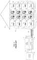
- FIG. 1 is a schematic illustration of an exemplary "last mile" connection in which a VDSL system and a G.Fast system share common copper infrastructure, which is known in the art.
- a typical "last mile" connection includes a building 10 G.Fast distribution point 20, VDSL Digital Subscriber Line Access Multiplexer (DSLAM) 21, and a central office 24.
- Building 10 includes, for example, eight apartments 12 1 -12 8 .
- Each of apartments 12 1 -12 8 includes, for example, a respective one of computers 14 1 -14 8 coupled with a respective one of modems 16 1 -16 8 either directly or via a router or hub (not shown).
- Each one of modems 16 1 -16 3 is coupled with VDSL DSLAM 21 via a respective one of line connections 18 1 -18 3 .
- Each one of modems 16 4 -16 8 is coupled with G.Fast distribution point 20 via a respective one of line connections 18 4 -18 8 .
- Line connections 18 1 -18 8 are also known as "drops".
- Each one of line connections 18 1 -18 8 is, for example, a twisted pair of wires.
- Each one of line connections 18 1 -18 8 may further be, for example, a coaxial cable.
- Line connections 18 1 -18 8 are grouped together within a binder 22.
- G.Fast distribution point 20 along with line connections 18 3 -18 8 , modems 16 4 -16 8 and computers 14 3 -14 8 constitute a G.Fast communication system.
- G.Fast distribution point 20 is coupled with Central office 24 via a communication channel 26 (e.g., optical cable, wireless channel).
- the distance between building 10 and distribution point 20 is up to the order of hundreds of meters and typically up to 200 meters.
- the distance between distribution point 20 and central office 24 is up to the order of several kilometers.
- VDSL DSLAM 21 along with line connections 18 1 -18 3 , modems 16 1 -16 3 and computers 14 1 -14 2 constitute a VDSL communication system.
- VDSL DSLAM 21 is coupled with Central office 24 via a communication channel 25 (e.g., optical cable, wireless channel).
- a communication channel 25 e.g., optical cable, wireless channel.
- the distance between building 10 and VDLS DSLAM 21 is up to the order of one km.
- the distance between VDSL DSLAM 21 and central office 24 is up to the order of several kilometers.
- computers 14 1 -14 8 are brought herein as an example only. Other devices require communication services (e.g., smart TV's, smartphones, IP phones, routers) may be coupled with the respective one of modems 16 1 -16 8 .
- building 10 may include offices rather than apartments. Additionally, the number of apartments or offices in building 10 may be different than eight (e.g. four, sixteen or twenty four). Additionally or alternatively, G.Fast distribution point 20 and VDSL DSLAM may each be connected to a plurality of private homes.
- G.fast employs Time Division Duplexing (TDD) technology. It utilizes the band from 2MHz to 106MHz, and is intended to be deployed in an environment where VDSL is already deployed.
- VDSL Very-high-bit-rate Digital Subscriber Line
- DSL Digital Subscriber Line
- the upstream/downstream transmissions are zipped in predefined frequency bands, as illustrated in Table 1 which follows: Table 1 Frequency [MHz] ⁇ 3.75 3.75-5.2 5.2-8.5 8.5-12 12-17.6 Down/Up Down Up Down Up Down Up Down Up Down
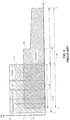
- FIG. 2 is a schematic illustration of the VDSL spectral mask 50 and the G.Fast spectral mask 52, which is known in the art.
- VDSL spectral mask 50 extends over the frequency range 54 between frequencies f 1 (e.g., 64 Kilohertz) and f 3 (e.g., 17.6 Megahertz).
- G.Fast spectral mask 52 extends over the frequency range 56 between extends between frequencies f 2 (e.g., 2 Megahertz) and f 5 (e.g., 106 Megahertz).
- VDSL spectral mask 50 allows for transmission at a power level of P1 (e.g., -58 dBm).
- G.Fast spectral mask 52 allows for transmission at a power lever of P2 (e.g., -65 dBm) between frequency f 1 and frequency f 4 and for a decreasing transmission power between P3 and P4 between frequency f 4 and frequency f 5 .
- Frequency f 4 shall also be referred to herein as the 'mask transition frequency'.
- frequency range 54 of VDSL spectral mask 50 overlaps with frequency range 56 of G.Fast spectral mask 52 over frequency range 58 between frequency f 2 and frequency f 3 .
- Frequency range 58 is also referred to herein as the 'overlapping frequency range'.
- Frequency range 60 is referred to herein as the 'non-overlapping frequency range'.
- a new communication system such as G.Fast, that is introduced to the copper infrastructure (plant), where pervious communication systems (e.g., VDSL) exist, may suffer from cross-talk as well as from signal attenuation which increases with frequency (i.e., low pass characteristics).
- the Analog Front End (AFE) of the new system is typically designed the receiver such that it supports the worst case scenario, that is, being able to process the highest attenuation at the highest frequency.
- a known in the art technique for employing G.Fast where VDSL is already installed, also referred to herein as 'the coexistence problem', is frequency separation, in which VDSL employs the frequencies allocated thereto while G.fast employs only the frequencies above the VDSL band (i.e., between f 3 and f 5 in Figure 2 ).
- G.Fast transmission shall only starts above the high cutoff frequency of VDSL transmission (e.g., 8 Megahertz, 12 Megahertz at 20 Megahertz 23 Megahertz or 30 Megahertz).
- G.Fast data rates i.e., also referred to herein as 'capacity'. This loss of capacity is mostly prominent in long lines where the higher frequencies may suffer from higher attenuation than the lower frequencies and may not carry any data.
- P.C.T Application Publication WO 2015/030817 to Kerpez et al entitled “Low Power System and Method for DSL Lines", directs to a system and method of low-power operation for DSL lines that combines the use of lower transmit power or lower transmit power spectral density (PSD) with the use of discontinuous operation.
- D1 directs to four different power states.
- the first power state is 'full power' (LO).
- the second power state is 'low transmit power' or 'low transmit PSD level' (L2.0).
- the third power state is 'lowest transmit power' or 'lowest transmit PSD' level (L2.I)
- the fourth power state is 'low transmit power' or 'low transmit PSD' level combined with discontinuous operation (L2.2).
- Discontinuous operation suspends transmission when there is no data traffic to send, or when data traffic transmission can be suspended, the data traffic queued during suspension, and then later resumed.
- the second, third and fourth power states are considered a power management modes, which reduces the power consumed by DSL modems (transceivers) for periods of time when there is little or no traffic on the line.
- G.Fast, G.VDSL2 Performance of G.Fast for Extended Reach
- Oksman V. ITU-T Draft, Study Period 2013-2016, ITU, Geneva, CH, vol. 4/15, 12/02/2015, pp. 1-8
- G.fast is deployed from a VDSL2 cabinet to serve higher bit rates to short reach customers.
- VDSL2 the G.fast distribution point is deployed from a separate location and doesn't share the cable binder with VDSL2.
- the disclosed technique overcomes the disadvantages of the prior art by providing a communication methods and systems adapted for operating over a communication channel susceptible to crosstalk due to at least partial frequency spectrum overlap by at least a second communication system different from the communication system.
- the disclosed technique is specifically applicable where the G.Fast transceivers are deployed in an environment where a VDSL communication system is already installed.
- a special case is when either the deployed VDSL communication system does not implement vectoring (i.e. a cross-talk cancellation technique) or the G.Fast loop length (i.e., the distance between the distribution point and the CPE) is relatively long (e.g., on the order of hundreds of meters) or both.
- vectoring i.e. a cross-talk cancellation technique
- G.Fast loop length i.e., the distance between the distribution point and the CPE
- Other applicable scenarios may also be relevant where two technologies share the same binder and spectrum. Nevertheless the disclosure herein relates to the example of G.Fast and VDSL communication system.
- a communication system may employ either the entire frequency spectrum thereof (i.e., regardless if a second communications system is active or in-active), referred to herein as "overlapping mode", or just the non-overlapping frequencies (e.g., where regulatory or coexistence constraints prohibit the use of the overlapping frequencies) referred to herein as "non-overlapping mode".
- the frequency spectrum employed by the G.Fast system includes at least a portion of the overlapping frequencies.
- the non-overlapping mode may be dynamic (i.e., "dynamic non-overlapping mode"). In other words, when the second communication system decreases or increases the frequency spectrum thereof, the communication system according to the disclosed technique increases or decreases the frequency spectrum thereof respectively.
- the term 'active' herein above and below relates to a communication system which transmits symbols over the communication channel thereof.
- the term 'in-active' or 'not-active' herein above and below relates to a communication system which at least does not transmit symbols over the communication channel thereof and my further be powered off.
- the G.Fast channel When a G.Fast communication system operates in an environment where a VDSL communication system may be active, the G.Fast channel is susceptible to cross-talk from the VDSL channel and vice versa.
- near end cross-talk i.e., NEXT
- the VDSL signals exhibit a higher power level than the G.Fast signals.
- the cross-talk of VDSL signals into the G.Fast channel may require reducing the gain at the G.Fast receiver (i.e., regardless of whether the spectrum of the two communication systems overlap or not), which may result in lower Signal to Noise Ratio (SNR) levels (i.e., relative to when VDSL is not installed).
- SNR Signal to Noise Ratio
- a lower SNR degrades the G.Fast system performance (e.g., bit-rate, Bit Error Rate - BER and the like).
- overlapping spectrum ranges of the VDSL and the G.Fast communication systems may result in a high NEXT level injected from G.Fast into VDSL. This may result in a lower SNR at the VDSL receiver and degradation in performance of an already deployed technology. This may not be acceptable by regulatory bodies or VDSL service providers, specifically if the VDSL communication system implements vectoring.
- a G.Fast communication system i.e., when operating in either the overlapping or non-overlapping modes
- employs a "shaping filter" in the G.Fast receivers i.e., either in the G.Fast DP, at the G.Fast CPE or both.
- the attenuation of this shaping filter in the low frequencies (and thus in the potentially overlapping frequency range when operating in the overlapping mode) of the received G.Fast signal is higher than the attenuation in the high frequency range as further explained below.
- the VDSL signals which exhibit a higher power relative to the G.Fast signals, are attenuated and the G.Fast receiver does not need to reduce the gain thereof.
- the G.Fast spectral mask allows for higher transmission power at the low frequencies than the transmission power at the high frequencies, and since the G.Fast channel exhibits low pass characteristics, the shaping filter can be employed without affecting the G.Fast signal transmission power.
- the shaping filter may also be employed for pre-conditioning regardless if VDSL cross-talk exists or not as further explained below.
- the VDSL downstream frequencies may be employed for both VDSL and G.Fast transmission. Since the power of the G.Fast signal is lower than the power of the VDSL signal, the Far End Crosstalk (FEXT) caused by the G.Fast signal shall result in FEXT power level at a VDSL receiver, which is lower than the FEXT power level produced by other VDSL transmitters. Thus, the G.Fast signal does not interfere with VDSL transmission and reception. As such, the G.Fast transmitter may transmit a signal at the highest possible level (i.e., as allowed by standard or regulation), without interfering with VDSL signals, thus improving the SNR of the G.Fast signal.
- the G.Fast transmitter may transmit a signal at the highest possible level (i.e., as allowed by standard or regulation), without interfering with VDSL signals, thus improving the SNR of the G.Fast signal.
- the G.Fast DL/UL ratio may be determined such that the cross-talk from G.Fast signals into VDSL signals exhibit substantially stationary statistical characteristics (i.e., quasi-stationary cross-talk statistics). (e.g., 90% of the G.Fast TDD frame is employed for downlink transmission).
- substantially stationary statistical characteristics i.e., quasi-stationary cross-talk statistics.
- the error introduced by the G.Fast FEXT, to the noise or SNR estimation performed by the VDSL downstream receiver is minimal.
- the difference between the average noise level measured by the VDSL downstream receiver and the worst case noise level is on the order of 0.5dB.
- Different DL/UL ratios may be employed (i.e., less than 90%) but the VDSL transceiver should allow for the lower SNR estimation such employ higher noise margin or adding virtual noise.
- the G.Fast communication system employs the VDSL downstream frequency bands during downstream transmission while refraining from employing the VDSL upstream frequency bands. Conversely, the G.Fast communication system may employ the VDSL upstream frequency bands during upstream transmission while refraining from employing the VDSL downstream frequency bands.
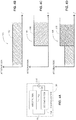
- System 100 includes a G.Fast distribution point 102 and a plurality of CPE transceivers 104 1 -104 N .
- G.Fast distribution point 102 includes a plurality of transceivers 106 1 -106 N .
- Transceiver 106 1 includes an Analog Front End (AFE) 108 a transformer 112 and a shaping filter 114.
- Transceiver 106 1 optionally includes a line driver 110.
- Line drive 110 may be located in AFE 108.
- AFE 108 includes a Programmable Gain Amplifier (PGA) 116.
- CPE transceiver 104 1 includes an AFE 118, a transformer 122 and a shaping filter 124.
- AFE 118 includes a PGA 126.
- CPE transceiver 104 1 optionally includes a line driver 120. Line driver 120 may be located in AFE 118.
- AFE 108 is coupled with transformer 112.
- transceiver 106 1 includes line driver 110
- line drive 110 is coupled between AFE 108 and transformer 112.
- Filter 114 is coupled with transformer 112 and with PGA 116.
- AFE 118 is coupled with transformer 122.
- CPE transceiver 104 1 includes line driver 120
- line drive 120 is coupled between AFE 108 and transformer 112.
- Filter 124 is coupled with transformer 122 and with PGA 126.
- Transformer 112 and transformer 122 are coupled therebetween via a communication channel 128 such as a twisted pair.
- AFE 108 receives a stream of symbols to be transmitted (e.g., in the form of analog In-phase and Quadrature-phase values), modulates these symbols and optionally up-converts the symbols.
- AFE 108 provides the modulated symbols to line driver 110.
- Line driver 110 amplifies the modulated symbols thereby generating a transmit signal to be transmitted to CPE transceiver 104 1 over channel 128 via transformers 112 and 122.
- CPE transceiver 104 1 receivers the transmitted signal and provides the received signal to Filter 124.
- the attenuation of shaping filter 124 in the overlapping frequency range is higher than the attenuation in the non-overlapping frequency range.
- Filter 124 provides the filtered received signal to PGA 126.
- VDSL signals which exhibit a higher power level relative to the G.Fast signals, are attenuated and there is no need to reduce the gain of PGA 126.
- reducing the gain of the G.Fast receiver i.e., of PGA 126) may result in a lower Signal to Noise Ratio (SNR) levels.
- AFE 118 receives a stream of symbols to be transmitted (e.g., in the form of analog In-phase and Quadrature-phase values), modulates these symbols and optionally up coverts the symbols. AFE 118 provides the modulated symbols to line driver 120. Line driver 120 amplifies the modulated symbols thereby generating a transmit signal to be transmitted to transceiver 106 1 over channel 128 via transformers 122 and 112. Transceiver 106 1 receives the transmitted signal and provides the received signal to Filter 114. Similar to filter 124, the attenuation of shaping filter 114 in the overlapping frequency range is higher than the attenuation in the non-overlapping frequency range. Filter 114 provides the filtered received signal to PGA 116.
- VDSL signals which exhibit a higher power relative to the G.Fast signals, are attenuated and there is no need to reduce the gain of PGA 116.
- An exemplary implementation and the frequency response of shaping filter 114 and shaping filter 124 are elaborated herein in conjunction with Figures 4A-4D .
- Figure 4A is a schematic illustration of an exemplary implementation of a shaping filter, generally referenced 150, constructed and operative in accordance with another embodiment of the disclosed technique.
- Figures 4B, 4C and 4D are schematic illustration of graphs, 160, 164 and 168 respectively, of respective frequency response 162, 166 and 170 also in accordance with another embodiment of the disclosed technique.
- Filter 150 includes a first filter 152, a second filter 154 and a summer 156.
- the input of first filter 152 and the input of second filter 154 are both coupled with the input of filter 150, demarked 'IN' in Figure 4A .
- the output of first filter 152 and input of second filter 154 are both coupled with the inputs of summer 156.
- the output of summer 156 is coupled with the output of filter 150, demarked 'OUT' in Figure 4A .
- First filter 152 exhibits a uniform frequency response similar to frequency response 162 ( Figure 4B ).
- first filter 125 may exhibit a low pass frequency response.
- Second filter 154 exhibits a high pass frequency response similar to frequency response 166 ( Figure 4C ).
- first filter 152 When first filter 152 exhibits a low pass frequency response, the high cutoff frequency of first filter 152 is higher than the low cutoff frequency of second filter 154. Also, the level of attenuation of second filter 154 in the pass band thereof is more than the level of attenuation of first filter 152 (i.e., also in the pass band thereof). In other words, at the pass band, second filter 154 attenuates the signal less than first filter 152. The output signals from first filter 152 and the output signals from second filter 154, summed by summer 156. The resulting signal shall exhibit a frequency response similar to frequency response 170. As such, the low frequencies are attenuated less than the high frequencies.
- the high frequencies are defined herein above and below as frequencies which are above the G.Fast transition frequency (i.e., f 4 in Figure 2 ) and low frequencies are defined herein above and below as frequencies below G.Fast transition frequency.
- a shaping filter such as shaping amplifier 150
- the G.Fast channel exhibits low pass characteristics.
- a shaping filter shall pre-condition the received signal according to the channel response. This filter also protects the receiver in case of power peaks in the channel.
- the high frequencies are defined as frequencies which are above the mask transition frequency and low frequencies are defined as frequencies below mask transition frequencies.
- a shaping filter such as shaping filter 150 may employed in any mode of operation of the system (i.e., overlapping mode, non-overlapping mode or dynamic non-overlapping mode).
- the disclosed technique enables employing the same hardware for the various conditions explained herein (e.g., VDSL cross-talk exists or not or for the various modes of operation) and transitions therebetween.
- a G.Fast communication system employs DMT where the available band width is divided into a plurality of sub-channels and determines the modulation scheme for each sub-channel (e.g., Quadrature Amplitude Modulation - QAM) such that the data transmission rate is maximized.
- the G.Fast communication system may refrain from using certain sub-channel, for example, when the SNR in a sub-channel decreases below a threshold (e.g., lower than 10 decibels, lower than 5 decibels).
- the G.Fast communication system employs the VDSL downstream frequency bands during downstream transmission while refraining from employing the VDSL upstream frequency bands.
- the G.Fast communication system employs the VDSL upstream frequency bands during upstream transmission while refraining from employing the VDSL downstream frequency bands.
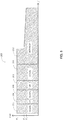
- FIG. 5 is a schematic illustration of a G.Fast spectral mask, generally referenced 200, in accordance with a further embodiment of the disclosed technique.
- a G.Fast communication system e.g., G.Fast communication system 100 - Figure 3
- the G.Fast communication system refrains from employing frequency bands 204 and 208, which correspond to the VDSL upstream frequency bands, during downstream transmission.
- the G.Fast communication system employs frequency bands 208 and 210, which correspond to the VDSL upstream frequency bands, while refraining from employing frequency bands 202, 206 and 210 (i.e., which correspond to the VDSL upstream frequency bands).
Claims (13)
- Système de communication utilisant une pluralité respective de canaux de communication, chacun desdits canaux de communication (128) étant susceptible de diaphonie à partir d'au moins un deuxième système de communication différent dudit système de communication, ledit au moins second système de communication employant une pluralité respective de communication des canaux, ledit système de communication et ledit au moins un second système de communication présentant une plage de fréquences qui se chevauchent (58), un masque spectral dudit deuxième système de communication présentant une densité de puissance supérieure à au moins une partie de ladite plage de fréquences se chevauchant qu'un masque spectral dudit système de communication, ledit système de communication fonctionnant dans l'un des modes de chevauchement et de non-chevauchement, ledit système de communication comprenant:
au moins une paire d'émetteurs-récepteurs comprenant un premier émetteur-récepteur et un deuxième émetteur-récepteur (1061, 1041), chaque émetteur-récepteur dans une paire d'émetteurs-récepteurs est situé d'un côté respectif de l'un respectif desdits canaux de communication (128), au moins le premier émetteur-récepteur de ladite paire d'émetteurs-récepteurs comprenant:une première extrémité avant analogique (108, 118), recevant un train de symboles à transmettre, ladite première extrémité avant analogique comprenant au moins un premier amplificateur de gain programmable (116, 126); etun premier filtre de mise en forme (114, 124) couplé à l'entrée dudit premier amplificateur à gain programmable (116, 126), l'atténuation dudit premier filtre de mise en forme (114, 118) dans la plage de fréquences de chevauchement (58) est supérieure à l'atténuation dudit premier filtre de mise en forme (1 14, 124) dans la plage de fréquences sans chevauchement (60), ledit premier filtre de mise en forme recevant un signal provenant de l'un respectif desdits canaux de communication et fournissant un signal reçu filtré à ladite première extrémité avant analogique. - Système de communication selon la revendication 1, dans lequel ledit premier filtre de mise en forme comprend un premier filtre en parallèle avec un deuxième filtre, ledit premier filtre présente une réponse en fréquence uniforme et une réponse en fréquence passe-bas, ledit deuxième filtre présente une réponse en fréquence passe-haut, et
dans lequel l'atténuation de bande passante dudit premier filtre de mise en forme est supérieure à l'atténuation de bande passante dudit second filtre. - Système de communication selon la revendication 1, dans lequel ledit deuxième émetteur-récepteur de ladite paire d'émetteurs-récepteurs comprend:une seconde extrémité avant analogique (108, 118), recevant un train de symboles à transmettre, ladite seconde extrémité avant analogique comprenant au moins un deuxième amplificateur de gain programmable (116, 126) ;un deuxième filtre de mise en forme (114, 124) couplé à l'entrée dudit deuxième amplificateur de gain programmable (116, 126), l'atténuation dudit deuxième filtre de mise en forme dans la plage de fréquences de chevauchement (58) est supérieure à l'atténuation dudit deuxième filtre de mise en forme (114, 124) dans la plage de fréquences non chevauchantes (60), ledit deuxième filtre de mise en forme recevant un signal provenant de l'un respectif desdits canaux de communication et fournissant un signal reçu filtré à ladite première extrémité avant analogique.
- Système de communication selon la revendication 3, dans lequel ledit premier émetteur-récepteur comprend en outre un premier pilote de ligne et un premier transformateur, une entrée dudit premier pilote de ligne est couplée avec la sortie de ladite première extrémité avant analogique et la sortie dudit premier pilote de ligne est couplée avec l'entrée dudit premier transformateur, ledit premier pilote de ligne étant destiné à amplifier des symboles.
- Système de communication selon la revendication 3, dans lequel ledit deuxième émetteur-récepteur comprend en outre un deuxième pilote de ligne et un deuxième transformateur, une entrée dudit deuxième pilote de ligne couplée à la sortie de ladite deuxième extrémité avant analogique et la sortie dudit second pilote de ligne est couplée à l'entrée dudit deuxième transformateur, ledit deuxième pilote de ligne étant destiné à amplifier des symboles.
- Système de communication selon la revendication 3, dans lequel ledit deuxième filtre de mise en forme comprend un premier filtre en parallèle avec un deuxième filtre, ledit premier filtre présente une réponse en fréquence uniforme et une réponse en fréquence passe-bas, ledit deuxième filtre présente une réponse en fréquence passe-haut, et
dans lequel l'atténuation de bande passante dudit premier filtre est supérieure à l'atténuation de bande passante dudit deuxième filtre. - Système de communication selon la revendication 1, dans lequel chaque paire d'émetteurs-récepteurs définit une liaison descendante entre ledit premier émetteur-récepteur et un deuxième émetteur-récepteur et définit en outre une liaison montante entre ledit deuxième émetteur-récepteur et ledit premier émetteur-récepteur.
- Système de communication selon la revendication 6, dans lequel la transmission de données dans ledit système de communication est divisée en trames de données, où chaque trame comprend une pluralité de tranches de temps chacune pour transmettre un symbole de données, une partie des symboles est désignée pour la transmission en liaison descendante et une autre partie des symboles est désignée pour la transmission sur la liaison montante, si le rapport des intervalles de temps de liaison descendante et des intervalles de temps de liaison montante est déterminé de telle sorte que la diaphonie du premier système de communication au second système de communication, les signaux présentent des caractéristiques statistiques substantiellement stationnaires.
- Système de communication selon la revendication 6, dans lequel lorsque ledit deuxième système de communication utilise un duplexage par répartition de fréquence où une partie des fréquences qui se chevauchent sont utilisées pour la transmission en aval et une autre partie est utilisée pour la transmission en amont, ledit système de communication utilise ladite partie des fréquences qui se chevauchent pour transmission en aval.
- Système de communication selon la revendication 6, dans lequel lorsque ledit deuxième système de communication utilise un duplexage par répartition en fréquence où une partie des fréquences qui se chevauchent sont utilisées pour la transmission en aval et une autre partie est utilisée pour la transmission en amont, ledit système de communication utilise ladite partie des fréquences qui se chevauchent pour une transmission en amont.
- Système de communication selon la revendication 1, dans lequel ledit système fonctionne en mode de chevauchement.
- Système de communication selon la revendication 1, dans lequel ledit système fonctionne en mode de chevauchement lorsque ledit deuxième système de communication n'est pas actif, et
dans lequel ledit système fonctionne en mode de non chevauchement lorsque ledit deuxième système de communication est actif. - Système selon la revendication 12, dans lequel ledit mode sans chevauchement est dynamique.
Applications Claiming Priority (3)
| Application Number | Priority Date | Filing Date | Title |
|---|---|---|---|
| US201562144938P | 2015-04-09 | 2015-04-09 | |
| US201662319309P | 2016-04-07 | 2016-04-07 | |
| PCT/IL2016/050376 WO2016162873A1 (fr) | 2015-04-09 | 2016-04-08 | Procédé et système de communication adaptés pour fonctionner simultanément sur un canal de communication sensible à la diaphonie à partir d'au moins un second système de communication |
Publications (3)
| Publication Number | Publication Date |
|---|---|
| EP3281299A1 EP3281299A1 (fr) | 2018-02-14 |
| EP3281299A4 EP3281299A4 (fr) | 2018-10-10 |
| EP3281299B1 true EP3281299B1 (fr) | 2020-06-03 |
Family
ID=57072350
Family Applications (1)
| Application Number | Title | Priority Date | Filing Date |
|---|---|---|---|
| EP16776228.5A Active EP3281299B1 (fr) | 2015-04-09 | 2016-04-08 | Procédé et système de communication adaptés pour fonctionner simultanément sur un canal de communication sensible à la diaphonie à partir d'au moins un second système de communication |
Country Status (4)
| Country | Link |
|---|---|
| US (1) | US10367546B2 (fr) |
| EP (1) | EP3281299B1 (fr) |
| IL (1) | IL254843B (fr) |
| WO (1) | WO2016162873A1 (fr) |
Families Citing this family (1)
| Publication number | Priority date | Publication date | Assignee | Title |
|---|---|---|---|---|
| WO2016162873A1 (fr) | 2015-04-09 | 2016-10-13 | Sckipio Technologies S.I Ltd | Procédé et système de communication adaptés pour fonctionner simultanément sur un canal de communication sensible à la diaphonie à partir d'au moins un second système de communication |
Family Cites Families (18)
| Publication number | Priority date | Publication date | Assignee | Title |
|---|---|---|---|---|
| US6055297A (en) * | 1996-08-02 | 2000-04-25 | Northern Telecom Limited | Reducing crosstalk between communications systems |
| WO2003050991A2 (fr) * | 2001-12-10 | 2003-06-19 | Globespan Virata, Inc. | Systeme et procede permettant d'ameliorer la transmission de donnees |
| US8064508B1 (en) | 2002-09-19 | 2011-11-22 | Silicon Image, Inc. | Equalizer with controllably weighted parallel high pass and low pass filters and receiver including such an equalizer |
| US7486937B2 (en) * | 2005-05-17 | 2009-02-03 | Cirrus Logic, Inc. | Efficient RF amplifier topologies |
| US7738567B2 (en) * | 2006-12-28 | 2010-06-15 | Texas Instruments Incorporated | Baseline wander correction for communication receivers |
| EP2234541B1 (fr) * | 2007-12-20 | 2016-05-04 | Koninklijke Philips N.V. | Filtre d'atténuation de tube stéréo |
| US7649973B1 (en) * | 2008-10-02 | 2010-01-19 | General Electric Company | Apparatus and method for z-location dependent x-ray beam filtration for imaging system |
| US9344307B2 (en) * | 2009-04-30 | 2016-05-17 | Ciena Corporation | Method and apparatus for sub-carrier frequency control |
| US8537912B2 (en) | 2011-02-24 | 2013-09-17 | Futurewei Technologies, Inc. | Extremely high speed broadband access over copper pairs |
| US8817903B2 (en) | 2012-02-17 | 2014-08-26 | Alcatel Lucent | Methods and systems for reducing crosstalk |
| EP2845325B1 (fr) * | 2012-05-02 | 2017-08-16 | Huawei Technologies Co., Ltd. | Alignement des symboles dmt dans le sens amont d'une pluralité de lignes dans un système tdd dsl |
| MX346807B (es) * | 2012-11-02 | 2017-03-31 | Huawei Tech Co Ltd | Método de transmisión de información, equipo de usuario, y estación base. |
| US20140161000A1 (en) * | 2012-12-10 | 2014-06-12 | Futurewei Technologies, Inc. | Timing offset correction in a tdd vectored system |
| EP2986062B1 (fr) * | 2013-05-03 | 2017-04-12 | Huawei Technologies Co., Ltd. | Procédé, dispositif et système de commande de puissance |
| US9900442B2 (en) | 2013-08-30 | 2018-02-20 | Adaptive Spectrum And Signal Alignment, Inc. | Low power system and method for DSL lines |
| US20150270942A1 (en) * | 2014-03-19 | 2015-09-24 | Ikanos Communications, Inc. | Methods and systems for maintaining spectral compatibility between co-existing legacy and wideband dsl services |
| US20160105215A1 (en) * | 2014-10-14 | 2016-04-14 | Futurewei Technologies, Inc. | Crosstalk Cancellation Over Multiple Mediums |
| WO2016162873A1 (fr) | 2015-04-09 | 2016-10-13 | Sckipio Technologies S.I Ltd | Procédé et système de communication adaptés pour fonctionner simultanément sur un canal de communication sensible à la diaphonie à partir d'au moins un second système de communication |
-
2016
- 2016-04-08 WO PCT/IL2016/050376 patent/WO2016162873A1/fr active Application Filing
- 2016-04-08 EP EP16776228.5A patent/EP3281299B1/fr active Active
- 2016-04-08 US US15/565,057 patent/US10367546B2/en active Active
-
2017
- 2017-10-02 IL IL254843A patent/IL254843B/en active IP Right Grant
Non-Patent Citations (1)
| Title |
|---|
| None * |
Also Published As
| Publication number | Publication date |
|---|---|
| US20180091190A1 (en) | 2018-03-29 |
| EP3281299A1 (fr) | 2018-02-14 |
| IL254843B (en) | 2018-04-30 |
| IL254843A0 (en) | 2017-12-31 |
| EP3281299A4 (fr) | 2018-10-10 |
| WO2016162873A1 (fr) | 2016-10-13 |
| US10367546B2 (en) | 2019-07-30 |
Similar Documents
| Publication | Publication Date | Title |
|---|---|---|
| US9906353B2 (en) | Scheme system and method for power saving in vectored communications | |
| US10797752B2 (en) | Communication coexistence in overlap spectrum | |
| EP2088686B1 (fr) | Procédé et dispositif de gestion du spectre de fréquences | |
| TWI565249B (zh) | 跨越共享傳輸介質的全雙工通訊 | |
| US7778346B2 (en) | Upstream power cutback | |
| US8908834B2 (en) | Method, apparatus, and system for reducing digital subscriber line interference | |
| US11411603B2 (en) | Device for transmitting and receiving on a copper wire installed at a customer premise | |
| EP2963904B1 (fr) | Opération de vectorisation améliorée avec fractionnement à boucle unique | |
| US10264136B2 (en) | Resource allocation in a digital communication network | |
| US11632145B2 (en) | Method and apparatus for full-duplex communication over wired transmission media | |
| US7839919B2 (en) | Adjusting transmit power spectra of transceiver devices in a communications network | |
| US9100176B2 (en) | Method and system for installing and operating discrete multi tone repeaters | |
| US20080057997A1 (en) | Method for shaping spectrum of output signal, and a remote access device | |
| EP3281299B1 (fr) | Procédé et système de communication adaptés pour fonctionner simultanément sur un canal de communication sensible à la diaphonie à partir d'au moins un second système de communication | |
| US20110211623A1 (en) | Method and system for applying dynamic spectral shaping to digital subscriber loop communication systems | |
| US20100246606A1 (en) | Optimizing the Transmit Power Spectrum Density (PSD) Of A Remotely Deployed Line to Ensure Spectral Compatibility | |
| Goran et al. | An Example of Wideband Services through Twisted Pair Technology Enhancement | |
| Cendrillon et al. | ANSI Standard Contribution 2003-325: On the Optimality of Iterative Waterfilling in DSL |
Legal Events
| Date | Code | Title | Description |
|---|---|---|---|
| STAA | Information on the status of an ep patent application or granted ep patent |
Free format text: STATUS: THE INTERNATIONAL PUBLICATION HAS BEEN MADE |
|
| PUAI | Public reference made under article 153(3) epc to a published international application that has entered the european phase |
Free format text: ORIGINAL CODE: 0009012 |
|
| STAA | Information on the status of an ep patent application or granted ep patent |
Free format text: STATUS: REQUEST FOR EXAMINATION WAS MADE |
|
| 17P | Request for examination filed |
Effective date: 20171009 |
|
| AK | Designated contracting states |
Kind code of ref document: A1 Designated state(s): AL AT BE BG CH CY CZ DE DK EE ES FI FR GB GR HR HU IE IS IT LI LT LU LV MC MK MT NL NO PL PT RO RS SE SI SK SM TR |
|
| AX | Request for extension of the european patent |
Extension state: BA ME |
|
| DAV | Request for validation of the european patent (deleted) | ||
| DAX | Request for extension of the european patent (deleted) | ||
| A4 | Supplementary search report drawn up and despatched |
Effective date: 20180910 |
|
| RIC1 | Information provided on ipc code assigned before grant |
Ipc: H04B 3/487 20150101ALI20180904BHEP Ipc: H04L 5/00 20060101ALI20180904BHEP Ipc: H04L 25/03 20060101ALI20180904BHEP Ipc: H04B 3/32 20060101AFI20180904BHEP |
|
| STAA | Information on the status of an ep patent application or granted ep patent |
Free format text: STATUS: EXAMINATION IS IN PROGRESS |
|
| 17Q | First examination report despatched |
Effective date: 20190424 |
|
| GRAP | Despatch of communication of intention to grant a patent |
Free format text: ORIGINAL CODE: EPIDOSNIGR1 |
|
| STAA | Information on the status of an ep patent application or granted ep patent |
Free format text: STATUS: GRANT OF PATENT IS INTENDED |
|
| INTG | Intention to grant announced |
Effective date: 20191118 |
|
| GRAS | Grant fee paid |
Free format text: ORIGINAL CODE: EPIDOSNIGR3 |
|
| GRAA | (expected) grant |
Free format text: ORIGINAL CODE: 0009210 |
|
| STAA | Information on the status of an ep patent application or granted ep patent |
Free format text: STATUS: THE PATENT HAS BEEN GRANTED |
|
| AK | Designated contracting states |
Kind code of ref document: B1 Designated state(s): AL AT BE BG CH CY CZ DE DK EE ES FI FR GB GR HR HU IE IS IT LI LT LU LV MC MK MT NL NO PL PT RO RS SE SI SK SM TR |
|
| REG | Reference to a national code |
Ref country code: GB Ref legal event code: FG4D |
|
| REG | Reference to a national code |
Ref country code: CH Ref legal event code: EP Ref country code: AT Ref legal event code: REF Ref document number: 1278108 Country of ref document: AT Kind code of ref document: T Effective date: 20200615 |
|
| REG | Reference to a national code |
Ref country code: DE Ref legal event code: R096 Ref document number: 602016037561 Country of ref document: DE |
|
| REG | Reference to a national code |
Ref country code: LT Ref legal event code: MG4D |
|
| PG25 | Lapsed in a contracting state [announced via postgrant information from national office to epo] |
Ref country code: GR Free format text: LAPSE BECAUSE OF FAILURE TO SUBMIT A TRANSLATION OF THE DESCRIPTION OR TO PAY THE FEE WITHIN THE PRESCRIBED TIME-LIMIT Effective date: 20200904 Ref country code: FI Free format text: LAPSE BECAUSE OF FAILURE TO SUBMIT A TRANSLATION OF THE DESCRIPTION OR TO PAY THE FEE WITHIN THE PRESCRIBED TIME-LIMIT Effective date: 20200603 Ref country code: LT Free format text: LAPSE BECAUSE OF FAILURE TO SUBMIT A TRANSLATION OF THE DESCRIPTION OR TO PAY THE FEE WITHIN THE PRESCRIBED TIME-LIMIT Effective date: 20200603 Ref country code: SE Free format text: LAPSE BECAUSE OF FAILURE TO SUBMIT A TRANSLATION OF THE DESCRIPTION OR TO PAY THE FEE WITHIN THE PRESCRIBED TIME-LIMIT Effective date: 20200603 Ref country code: NO Free format text: LAPSE BECAUSE OF FAILURE TO SUBMIT A TRANSLATION OF THE DESCRIPTION OR TO PAY THE FEE WITHIN THE PRESCRIBED TIME-LIMIT Effective date: 20200903 |
|
| REG | Reference to a national code |
Ref country code: NL Ref legal event code: MP Effective date: 20200603 |
|
| PG25 | Lapsed in a contracting state [announced via postgrant information from national office to epo] |
Ref country code: HR Free format text: LAPSE BECAUSE OF FAILURE TO SUBMIT A TRANSLATION OF THE DESCRIPTION OR TO PAY THE FEE WITHIN THE PRESCRIBED TIME-LIMIT Effective date: 20200603 Ref country code: RS Free format text: LAPSE BECAUSE OF FAILURE TO SUBMIT A TRANSLATION OF THE DESCRIPTION OR TO PAY THE FEE WITHIN THE PRESCRIBED TIME-LIMIT Effective date: 20200603 Ref country code: BG Free format text: LAPSE BECAUSE OF FAILURE TO SUBMIT A TRANSLATION OF THE DESCRIPTION OR TO PAY THE FEE WITHIN THE PRESCRIBED TIME-LIMIT Effective date: 20200903 Ref country code: LV Free format text: LAPSE BECAUSE OF FAILURE TO SUBMIT A TRANSLATION OF THE DESCRIPTION OR TO PAY THE FEE WITHIN THE PRESCRIBED TIME-LIMIT Effective date: 20200603 |
|
| REG | Reference to a national code |
Ref country code: AT Ref legal event code: MK05 Ref document number: 1278108 Country of ref document: AT Kind code of ref document: T Effective date: 20200603 |
|
| PG25 | Lapsed in a contracting state [announced via postgrant information from national office to epo] |
Ref country code: NL Free format text: LAPSE BECAUSE OF FAILURE TO SUBMIT A TRANSLATION OF THE DESCRIPTION OR TO PAY THE FEE WITHIN THE PRESCRIBED TIME-LIMIT Effective date: 20200603 Ref country code: AL Free format text: LAPSE BECAUSE OF FAILURE TO SUBMIT A TRANSLATION OF THE DESCRIPTION OR TO PAY THE FEE WITHIN THE PRESCRIBED TIME-LIMIT Effective date: 20200603 |
|
| PG25 | Lapsed in a contracting state [announced via postgrant information from national office to epo] |
Ref country code: ES Free format text: LAPSE BECAUSE OF FAILURE TO SUBMIT A TRANSLATION OF THE DESCRIPTION OR TO PAY THE FEE WITHIN THE PRESCRIBED TIME-LIMIT Effective date: 20200603 Ref country code: PT Free format text: LAPSE BECAUSE OF FAILURE TO SUBMIT A TRANSLATION OF THE DESCRIPTION OR TO PAY THE FEE WITHIN THE PRESCRIBED TIME-LIMIT Effective date: 20201006 Ref country code: SM Free format text: LAPSE BECAUSE OF FAILURE TO SUBMIT A TRANSLATION OF THE DESCRIPTION OR TO PAY THE FEE WITHIN THE PRESCRIBED TIME-LIMIT Effective date: 20200603 Ref country code: EE Free format text: LAPSE BECAUSE OF FAILURE TO SUBMIT A TRANSLATION OF THE DESCRIPTION OR TO PAY THE FEE WITHIN THE PRESCRIBED TIME-LIMIT Effective date: 20200603 Ref country code: IT Free format text: LAPSE BECAUSE OF FAILURE TO SUBMIT A TRANSLATION OF THE DESCRIPTION OR TO PAY THE FEE WITHIN THE PRESCRIBED TIME-LIMIT Effective date: 20200603 Ref country code: AT Free format text: LAPSE BECAUSE OF FAILURE TO SUBMIT A TRANSLATION OF THE DESCRIPTION OR TO PAY THE FEE WITHIN THE PRESCRIBED TIME-LIMIT Effective date: 20200603 Ref country code: CZ Free format text: LAPSE BECAUSE OF FAILURE TO SUBMIT A TRANSLATION OF THE DESCRIPTION OR TO PAY THE FEE WITHIN THE PRESCRIBED TIME-LIMIT Effective date: 20200603 Ref country code: RO Free format text: LAPSE BECAUSE OF FAILURE TO SUBMIT A TRANSLATION OF THE DESCRIPTION OR TO PAY THE FEE WITHIN THE PRESCRIBED TIME-LIMIT Effective date: 20200603 |
|
| PG25 | Lapsed in a contracting state [announced via postgrant information from national office to epo] |
Ref country code: PL Free format text: LAPSE BECAUSE OF FAILURE TO SUBMIT A TRANSLATION OF THE DESCRIPTION OR TO PAY THE FEE WITHIN THE PRESCRIBED TIME-LIMIT Effective date: 20200603 Ref country code: SK Free format text: LAPSE BECAUSE OF FAILURE TO SUBMIT A TRANSLATION OF THE DESCRIPTION OR TO PAY THE FEE WITHIN THE PRESCRIBED TIME-LIMIT Effective date: 20200603 Ref country code: IS Free format text: LAPSE BECAUSE OF FAILURE TO SUBMIT A TRANSLATION OF THE DESCRIPTION OR TO PAY THE FEE WITHIN THE PRESCRIBED TIME-LIMIT Effective date: 20201003 |
|
| REG | Reference to a national code |
Ref country code: DE Ref legal event code: R097 Ref document number: 602016037561 Country of ref document: DE |
|
| PLBE | No opposition filed within time limit |
Free format text: ORIGINAL CODE: 0009261 |
|
| STAA | Information on the status of an ep patent application or granted ep patent |
Free format text: STATUS: NO OPPOSITION FILED WITHIN TIME LIMIT |
|
| PG25 | Lapsed in a contracting state [announced via postgrant information from national office to epo] |
Ref country code: DK Free format text: LAPSE BECAUSE OF FAILURE TO SUBMIT A TRANSLATION OF THE DESCRIPTION OR TO PAY THE FEE WITHIN THE PRESCRIBED TIME-LIMIT Effective date: 20200603 |
|
| 26N | No opposition filed |
Effective date: 20210304 |
|
| PG25 | Lapsed in a contracting state [announced via postgrant information from national office to epo] |
Ref country code: SI Free format text: LAPSE BECAUSE OF FAILURE TO SUBMIT A TRANSLATION OF THE DESCRIPTION OR TO PAY THE FEE WITHIN THE PRESCRIBED TIME-LIMIT Effective date: 20200603 |
|
| PG25 | Lapsed in a contracting state [announced via postgrant information from national office to epo] |
Ref country code: MC Free format text: LAPSE BECAUSE OF FAILURE TO SUBMIT A TRANSLATION OF THE DESCRIPTION OR TO PAY THE FEE WITHIN THE PRESCRIBED TIME-LIMIT Effective date: 20200603 |
|
| PG25 | Lapsed in a contracting state [announced via postgrant information from national office to epo] |
Ref country code: LU Free format text: LAPSE BECAUSE OF NON-PAYMENT OF DUE FEES Effective date: 20210408 |
|
| REG | Reference to a national code |
Ref country code: BE Ref legal event code: MM Effective date: 20210430 |
|
| PG25 | Lapsed in a contracting state [announced via postgrant information from national office to epo] |
Ref country code: FR Free format text: LAPSE BECAUSE OF NON-PAYMENT OF DUE FEES Effective date: 20210430 Ref country code: CH Free format text: LAPSE BECAUSE OF NON-PAYMENT OF DUE FEES Effective date: 20210430 Ref country code: LI Free format text: LAPSE BECAUSE OF NON-PAYMENT OF DUE FEES Effective date: 20210430 |
|
| PG25 | Lapsed in a contracting state [announced via postgrant information from national office to epo] |
Ref country code: IE Free format text: LAPSE BECAUSE OF NON-PAYMENT OF DUE FEES Effective date: 20210408 |
|
| PG25 | Lapsed in a contracting state [announced via postgrant information from national office to epo] |
Ref country code: IS Free format text: LAPSE BECAUSE OF FAILURE TO SUBMIT A TRANSLATION OF THE DESCRIPTION OR TO PAY THE FEE WITHIN THE PRESCRIBED TIME-LIMIT Effective date: 20201003 |
|
| PG25 | Lapsed in a contracting state [announced via postgrant information from national office to epo] |
Ref country code: BE Free format text: LAPSE BECAUSE OF NON-PAYMENT OF DUE FEES Effective date: 20210430 |
|
| PG25 | Lapsed in a contracting state [announced via postgrant information from national office to epo] |
Ref country code: HU Free format text: LAPSE BECAUSE OF FAILURE TO SUBMIT A TRANSLATION OF THE DESCRIPTION OR TO PAY THE FEE WITHIN THE PRESCRIBED TIME-LIMIT; INVALID AB INITIO Effective date: 20160408 |
|
| PG25 | Lapsed in a contracting state [announced via postgrant information from national office to epo] |
Ref country code: CY Free format text: LAPSE BECAUSE OF FAILURE TO SUBMIT A TRANSLATION OF THE DESCRIPTION OR TO PAY THE FEE WITHIN THE PRESCRIBED TIME-LIMIT Effective date: 20200603 |
|
| P01 | Opt-out of the competence of the unified patent court (upc) registered |
Effective date: 20230530 |
|
| PGFP | Annual fee paid to national office [announced via postgrant information from national office to epo] |
Ref country code: DE Payment date: 20230412 Year of fee payment: 8 |
|
| PGFP | Annual fee paid to national office [announced via postgrant information from national office to epo] |
Ref country code: GB Payment date: 20230419 Year of fee payment: 8 |
|
| PG25 | Lapsed in a contracting state [announced via postgrant information from national office to epo] |
Ref country code: MK Free format text: LAPSE BECAUSE OF FAILURE TO SUBMIT A TRANSLATION OF THE DESCRIPTION OR TO PAY THE FEE WITHIN THE PRESCRIBED TIME-LIMIT Effective date: 20200603 |