EP3281089B1 - Smart device and method of operating the same - Google Patents
Smart device and method of operating the same Download PDFInfo
- Publication number
- EP3281089B1 EP3281089B1 EP16833246.8A EP16833246A EP3281089B1 EP 3281089 B1 EP3281089 B1 EP 3281089B1 EP 16833246 A EP16833246 A EP 16833246A EP 3281089 B1 EP3281089 B1 EP 3281089B1
- Authority
- EP
- European Patent Office
- Prior art keywords
- smart device
- interrupt signal
- sensor
- movement
- processor
- Prior art date
- Legal status (The legal status is an assumption and is not a legal conclusion. Google has not performed a legal analysis and makes no representation as to the accuracy of the status listed.)
- Active
Links
Images


Classifications
-
- G—PHYSICS
- G06—COMPUTING; CALCULATING OR COUNTING
- G06F—ELECTRIC DIGITAL DATA PROCESSING
- G06F13/00—Interconnection of, or transfer of information or other signals between, memories, input/output devices or central processing units
- G06F13/14—Handling requests for interconnection or transfer
- G06F13/20—Handling requests for interconnection or transfer for access to input/output bus
- G06F13/24—Handling requests for interconnection or transfer for access to input/output bus using interrupt
-
- G—PHYSICS
- G06—COMPUTING; CALCULATING OR COUNTING
- G06F—ELECTRIC DIGITAL DATA PROCESSING
- G06F3/00—Input arrangements for transferring data to be processed into a form capable of being handled by the computer; Output arrangements for transferring data from processing unit to output unit, e.g. interface arrangements
- G06F3/01—Input arrangements or combined input and output arrangements for interaction between user and computer
-
- G—PHYSICS
- G06—COMPUTING; CALCULATING OR COUNTING
- G06F—ELECTRIC DIGITAL DATA PROCESSING
- G06F1/00—Details not covered by groups G06F3/00 - G06F13/00 and G06F21/00
- G06F1/16—Constructional details or arrangements
- G06F1/1613—Constructional details or arrangements for portable computers
- G06F1/1633—Constructional details or arrangements of portable computers not specific to the type of enclosures covered by groups G06F1/1615 - G06F1/1626
- G06F1/1684—Constructional details or arrangements related to integrated I/O peripherals not covered by groups G06F1/1635 - G06F1/1675
- G06F1/1694—Constructional details or arrangements related to integrated I/O peripherals not covered by groups G06F1/1635 - G06F1/1675 the I/O peripheral being a single or a set of motion sensors for pointer control or gesture input obtained by sensing movements of the portable computer
-
- G—PHYSICS
- G06—COMPUTING; CALCULATING OR COUNTING
- G06F—ELECTRIC DIGITAL DATA PROCESSING
- G06F1/00—Details not covered by groups G06F3/00 - G06F13/00 and G06F21/00
- G06F1/26—Power supply means, e.g. regulation thereof
- G06F1/32—Means for saving power
- G06F1/3203—Power management, i.e. event-based initiation of a power-saving mode
-
- G—PHYSICS
- G06—COMPUTING; CALCULATING OR COUNTING
- G06F—ELECTRIC DIGITAL DATA PROCESSING
- G06F3/00—Input arrangements for transferring data to be processed into a form capable of being handled by the computer; Output arrangements for transferring data from processing unit to output unit, e.g. interface arrangements
- G06F3/01—Input arrangements or combined input and output arrangements for interaction between user and computer
- G06F3/03—Arrangements for converting the position or the displacement of a member into a coded form
- G06F3/033—Pointing devices displaced or positioned by the user, e.g. mice, trackballs, pens or joysticks; Accessories therefor
- G06F3/0346—Pointing devices displaced or positioned by the user, e.g. mice, trackballs, pens or joysticks; Accessories therefor with detection of the device orientation or free movement in a 3D space, e.g. 3D mice, 6-DOF [six degrees of freedom] pointers using gyroscopes, accelerometers or tilt-sensors
-
- G—PHYSICS
- G06—COMPUTING; CALCULATING OR COUNTING
- G06F—ELECTRIC DIGITAL DATA PROCESSING
- G06F3/00—Input arrangements for transferring data to be processed into a form capable of being handled by the computer; Output arrangements for transferring data from processing unit to output unit, e.g. interface arrangements
- G06F3/01—Input arrangements or combined input and output arrangements for interaction between user and computer
- G06F3/048—Interaction techniques based on graphical user interfaces [GUI]
- G06F3/0481—Interaction techniques based on graphical user interfaces [GUI] based on specific properties of the displayed interaction object or a metaphor-based environment, e.g. interaction with desktop elements like windows or icons, or assisted by a cursor's changing behaviour or appearance
- G06F3/0482—Interaction with lists of selectable items, e.g. menus
-
- G—PHYSICS
- G06—COMPUTING; CALCULATING OR COUNTING
- G06F—ELECTRIC DIGITAL DATA PROCESSING
- G06F3/00—Input arrangements for transferring data to be processed into a form capable of being handled by the computer; Output arrangements for transferring data from processing unit to output unit, e.g. interface arrangements
- G06F3/01—Input arrangements or combined input and output arrangements for interaction between user and computer
- G06F3/048—Interaction techniques based on graphical user interfaces [GUI]
- G06F3/0484—Interaction techniques based on graphical user interfaces [GUI] for the control of specific functions or operations, e.g. selecting or manipulating an object, an image or a displayed text element, setting a parameter value or selecting a range
-
- H—ELECTRICITY
- H04—ELECTRIC COMMUNICATION TECHNIQUE
- H04W—WIRELESS COMMUNICATION NETWORKS
- H04W52/00—Power management, e.g. TPC [Transmission Power Control], power saving or power classes
- H04W52/02—Power saving arrangements
- H04W52/0209—Power saving arrangements in terminal devices
- H04W52/0251—Power saving arrangements in terminal devices using monitoring of local events, e.g. events related to user activity
- H04W52/0254—Power saving arrangements in terminal devices using monitoring of local events, e.g. events related to user activity detecting a user operation or a tactile contact or a motion of the device
-
- Y—GENERAL TAGGING OF NEW TECHNOLOGICAL DEVELOPMENTS; GENERAL TAGGING OF CROSS-SECTIONAL TECHNOLOGIES SPANNING OVER SEVERAL SECTIONS OF THE IPC; TECHNICAL SUBJECTS COVERED BY FORMER USPC CROSS-REFERENCE ART COLLECTIONS [XRACs] AND DIGESTS
- Y02—TECHNOLOGIES OR APPLICATIONS FOR MITIGATION OR ADAPTATION AGAINST CLIMATE CHANGE
- Y02D—CLIMATE CHANGE MITIGATION TECHNOLOGIES IN INFORMATION AND COMMUNICATION TECHNOLOGIES [ICT], I.E. INFORMATION AND COMMUNICATION TECHNOLOGIES AIMING AT THE REDUCTION OF THEIR OWN ENERGY USE
- Y02D30/00—Reducing energy consumption in communication networks
- Y02D30/70—Reducing energy consumption in communication networks in wireless communication networks
Definitions
- the present disclosure relates to electronic apparatuses and methods of operating the same. More particularly, the present disclosure relates to an electronic apparatus for displaying a graphic user interface (GUI) element, and a method of operating the electronic apparatus.
- GUI graphic user interface
- An accelerometer sensor is one of commonly used motion sensors and is used in various solutions, such as for a pedometer, screen rotation, automatic brightness, and free fall detection. Algorithms in all such cases require accelerometer data to be polled not only at 100 Hz, but also at 5 Hz, 16 Hz, and 50 Hz.
- a device having a sensor operates using the following two methods.
- a sensor is connected to an application processor (AP).
- the AP is in a wake up state to receive data and periodically polls the sensor.
- a sensor is connected to a microcontroller (MCU, i.e., a sensor hub).
- An AP may sleep and the MCU may be sleepwalking. Processing may occur in the MCU, and the MCU may wake up the AP when necessary.
- the MCU periodically polls the sensor.
- a major disadvantage of such a polling method is that a system requires uninterrupted polling of accelerometer data either from an AP or from an MCU. As a result, there is a possibility that battery performance may largely deteriorate because such a polling method requires a huge amount of processing and continuous polling with respect to a sensor and the sensor needs to operate in a normal mode. Latency in data is another big problem in an MCU-based method. Accelerometer data may be available to an upper layer through a polling mechanism and is used in the upper layer for decision making for all algorithms. Due to the polling mechanism and complex decision making processes accompanied by mathematical operations or signal processing, sluggish behavior may be generated, and thus it may be impossible to receive real-time responses.
- accelerometer data is transmitted to an application layer by using a polling mechanism.
- a polling mechanism Such an operation is intensive for a central processing unit (CPU), and thus a data receiving rate is reduced.
- Most applications access data by using the polling mechanism.
- the data is processed in an uppermost layer and then necessary actions to be taken are determined according to algorithms. Accordingly, a possibility of a high-speed response is reduced in cases where a fall is detected.
- Due to the polling mechanism CPU million instructions per second (MIPS) are wasted and thus power consumption is increased.
- US2014/0059365A1 discloses an apparatus having an interrupt sensor for waking up a main processor.
- EP2317744A1 discloses a system for activating an electronic device comprising a motion detection circuit.
- EP2683204A1 discloses a method for controlling a sleep mode in a portable terminal.
- an aspect of the present disclosure is to provide a smart device for reducing power consumption and enabling a fast response, and a method of operating the smart device.
- the invention is defined by the independent claims. Further aspects of the invention are outlined in the dependent claims. In the following, if the term "embodiment” relates to unclaimed combinations of features, said term has to be understood as referring to non-claimed matter considered to be useful for highlighting specific aspects of the claimed subject-matter.
- a decision making delay is avoided, and specifically, a method of providing a real-time high-speed response in a decision making situation where time is very important may be achieved.
- processing in an AP is removed, and by reducing space and operation complexity, power consumption may be reduced and performance of a smart device may be increased.
- One or more embodiments of the present disclosure do not require an additional hardware block or a microprocessor that requires high processing. Also, a power number of a microprocessor may be relatively decreased compared to another microprocessor, without capability deterioration.
- a smart device in accordance with an aspect of the present disclosure, includes a processor, and a sensor configured to detect movement of the smart device, generate an interrupt signal including information on a movement range corresponding to at least one movement type determined based on the detected movement, and output the interrupt signal to the processor and the processor is configured to control an action, corresponding to the interrupt signal received from the sensor, to be performed in response to the interrupt signal.
- the information on the movement range included in the interrupt signal may include at least one of an identifier indicating the at least one movement type, or a value indicating the movement range corresponding to a direction or magnitude of the movement.
- the sensor may include one or more algorithms, and may be configured to determine each of the at least one movement type, in which the one or more algorithms may each be settable to be enabled or disabled.
- the one or more algorithms may each be settable to be enabled or disabled according to a user setting received from a user interface.
- the processor may be further configured to wake up from a low power mode to a normal mode in response to the interrupt signal received from the sensor.
- the sensor may be further configured to calculate at least one of a tilt angle or a rotation angle of the smart device based on sensing data from detecting the movement of the smart device, evaluate at least one of the tilt angle or the rotation angle based on at least one of a rotation angle table or a tilt angle table, which is pre-stored, and generate the interrupt signal including the information on the movement range based on a result of an evaluation.
- the rotation angle table may include a range value corresponding to the rotation angle
- the tilt angle table may include a range value corresponding to the tilt angle
- a method of operating a smart device includes detecting, by a sensor, movement of the smart device, generating an interrupt signal including information on a movement range corresponding to at least one movement type determined based on the movement, outputting the interrupt signal to a processor and controlling, by the processor, an action, corresponding to the interrupt signal, to be performed in response to the interrupt signal received from the sensor.
- a non-transitory computer-readable recording medium has recorded thereon a program code for executing the method.
- first may be referred to as a second component
- second component may be referred to as a first component while not departing from the scope of the present disclosure.
- the term “and/or” includes any and all combinations of one or more of the associated listed items. Expressions such as “at least one of”, when preceding a list of elements, modify the entire list of elements and do not modify the individual elements of the list.
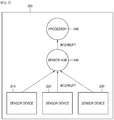
- FIG. 1 is a reference diagram of an example for describing a concept according to an embodiment of the present disclosure.
- a smart device 100 includes sensor devices 110 through 130, and a processor 140.
- the smart device 100 may include one or more sensor devices.
- FIG. 1 for example, three sensor devices 110 through 130 are shown, but the number of sensor devices may be one or more.
- the sensor devices 110 through 130 may include a sensor for detecting movement of the smart device 100, and a small scale processor or small scale circuit for generating and processing an interrupt signal.
- a sensor device including a sensor and a small scale processor or small scale circuit may also be simply referred to as a sensor.
- At least one of the sensor devices 110 through 130 may detect movement of the smart device 100, generate an interrupt signal corresponding to the movement, and transmit the interrupt signal to the processor 140.
- At least one of the sensor devices 110 through 130 may detect the movement of the smart device 100, and generate an interrupt signal including information on a movement range corresponding to at least one movement type determined based on the movement.
- the information on the movement range included in the interrupt signal may include at least one of an identifier including the movement type, and a value indicating the movement range corresponding to a direction or magnitude of the movement.
- each of the sensor devices 110 through 130 includes one or more modules determining each movement type, and the one or more modules may each be set to be enabled or disabled. Also, the one or more modules may each be set to be enabled or disabled according to a user setting received from a user interface.
- each of the sensor devices 110 through 130 may calculate at least one of a tilt angle and a rotation angle of the smart device 100 based on sensing data from detecting the movement of the smart device 100, evaluate at least one of the tilt angle and the rotation angle based on at least one of a rotation angle table and a tilt angle table, which is pre-stored, and generate the interrupt signal including the information on the movement range based on a result of the evaluation.
- the rotation angle table may include a range value corresponding to one or more rotation angles
- the tilt angle table may include a range value corresponding to one or more tilt angles
- the processor 140 processes overall operations of the smart device 100, wherein the processor 140 may receive an interrupt signal from at least one of the sensor devices 110 through 130 while the processor 140 is in a low power mode, and wake up from the low power mode to a normal mode in response to the interrupt signal. Also, the processor 140 may perform one or more actions corresponding to the interrupt signal.
- the one or more actions corresponding to the interrupt signal may include, for example, displaying of a certain message or a certain user interface on a display, outputting of a certain alarm, and transmitting of a notification to a certain destination, and may include any action performable by using a module included in the smart device 100.
- the processor 140 may include an application processor (AP).
- AP application processor
- FIG. 1 unlike a general processor that is in a wake up state to poll a sensor to periodically detect movement, at least one of the sensor devices 110 through 130 actively wakes up the processor 140 in a low power mode when movement is detected, and thus power consumption of the processor 140 is reduced and a load of the processor 140 that is generally always polling may be reduced.
- the smart device 100 may be a device having a communication function.
- the smart device 100 may include at least one of a smart phone, a tablet personal computer (PC), a mobile phone, a video phone, an e-book reader, a desktop PC, a laptop PC, a netbook computer, a personal digital assistant (PDA), a portable multimedia player (PMP), a Moving Picture Experts Group phase 1 or phase 2 (MPEG-1 or MPEG-2) audio layer 3 (MP3) player, a mobile medical device, a camera, and a wearable device (for example, a head-mounted device (HMD) like electronic glasses, an electronic dress, an electronic bracelet, an electronic necklace, an electronic accessory, an electronic tattoo, or a smart watch).
- HMD head-mounted device
- the smart device 100 may be one of various devices described above, or a combination thereof. Also, the smart device 100 according to various embodiments may be a flexible device. Also, it would be obvious to one of ordinary skill in the art that the smart device 100 according to various embodiments is not limited to the above devices.
- FIG. 2 is a reference diagram of another example for describing a concept according to an embodiment of the present disclosure.
- a smart device 200 includes sensor devices 210 through 230, a sensor hub 240, and a processor 250.
- the sensor devices 210 through 230 and the processor 250 perform the same operations as those shown in FIG. 1 , and a difference between the smart device 100 of FIG. 1 and the smart device 200 of FIG. 2 is that the smart device 200 further includes the sensor hub 240.
- the sensor hub 240 is also referred to as a sensor sub-system, and manages the sensor devices 210 through 230.
- the sensor hub 240 may wake up and enter into a normal mode upon receiving an interrupt signal from at least one of the sensor devices 210 through 230 while the sensor hub 240 is in a low power mode, manage the interrupt signal, and transmit the interrupt signal to the processor 250 in a low power mode.
- the processor 250 may wake up from the low power mode upon receiving the interrupt signal from the sensor hub 240, and perform one or more actions corresponding to the interrupt signal.
- FIG. 3 is a block diagram of a smart device 300 according to an embodiment of the present disclosure.
- a smart device includes a sensor device 310, an AP 320, a memory 330, a communication interface 340, a display 350, an audio input and output interface 360, an input and output interface 370, and a power supply 380.
- the sensor device 310 may measure a physical quantity or detect an operation state of the smart device 300, and convert measured or detected information to an electric signal.
- the sensor device 310 may include, for example, at least one of a gesture sensor, a gyro sensor, an atmospheric sensor, a magnetic sensor, an acceleration sensor, a grip sensor, a proximity sensor, a color sensor, a biometric sensor, a temperature/humidity sensor, an illumination sensor, and an ultraviolet (UV) sensor.
- the sensor device 310 may include, for example, an e-nose sensor, an electromyography (EMG) sensor, an electroencephalogram (EEG) sensor, an electrocardiogram (ECG) sensor, an infrared ray (IR) sensor, an iris sensor, or a fingerprint sensor.
- EMG electromyography
- EEG electroencephalogram
- ECG electrocardiogram
- IR infrared ray
- iris sensor an iris sensor
- a fingerprint sensor for example, an e-nose sensor, an electromyography (EMG) sensor, an electroencephalogram (EEG) sensor, an electrocardiogram (ECG) sensor, an infrared ray (IR) sensor, an iris sensor, or a fingerprint sensor.
- the sensor device 310 may further include a control circuit for controlling at least one sensor included in the sensor device 310.
- the sensor device 310 may measure the physical quantity of the smart device 300 even in a lower power mode of the smart device 300, generate an interrupt signal according to the measurement, and transmit the interrupt signal to the AP 320 in a low power mode.
- the sensor device 310 may detect a tilt angle or a rotation angle of the smart device 300.
- the AP 320 may, for example, receive a command from another component described above (for example, the memory 330, the input and output interface 370, the display 350, or the communication interface 340) through a bus 390, decode the command, and perform a data process or an operation according to the command.
- another component described above for example, the memory 330, the input and output interface 370, the display 350, or the communication interface 340
- the AP 320 may control a plurality of hardware or software components connected to the AP 320 by driving an operating system (OS) or an application program, and perform various data processes and operations including multimedia data.
- the AP 320 may be, for example, realized as a system-on-chip (SoC).
- SoC system-on-chip
- the AP 320 may further include a graphics processing unit (GPU).
- the AP 320 may receive an interrupt signal from the sensor device 310 while the AP 320 is in a low power mode, and wake up from the low power mode to a normal mode in response to the interrupt signal. Also, the AP 320 may perform one or more actions corresponding to the interrupt signal, in response to the interrupt signal. The one or more actions performed by the AP 320 according to the interrupt signal may be stored in the memory 330.
- the one or more actions may include, for example, transmitting a notification to another device through the communication interface 340, turning on the display 350 and outputting a certain message or a certain user interface to the display 350, turning on the audio input and output interface 360 and outputting a certain sound, and inputting and outputting data by using the input and output interface 370.
- the memory 330 may store a command or data received from or generated by the AP 320 or another component (for example, the input and output interface 370, the display 350, or the communication interface 340).
- the memory 330 may include, for example, program modules, such as a kernel, middleware, an application programming interface (API), and an application. Each programming module may include software, firmware, hardware, or a combination thereof.
- the memory 330 may include an internal memory or an external memory.
- the internal memory may include, for example, at least one of a volatile memory (for example, a dynamic random access memory (DRAM), a static RAM (SRAM), or a synchronous DRAM (SDRAM)), and a non-volatile memory (for example, a one-time programmable read-only memory (OTPROM), a programmable ROM (PROM), an erasable and programmable ROM (EPROM), an electrically erasable and programmable ROM (EEPROM), a mask ROM, a flash ROM, a NAND flash memory, or a NOR flash memory).
- a volatile memory for example, a dynamic random access memory (DRAM), a static RAM (SRAM), or a synchronous DRAM (SDRAM)
- a non-volatile memory for example, a one-time programmable read-only memory (OTPROM), a programmable ROM (PROM), an erasable and programmable ROM (EPROM), an electrically erasable and
- the external memory may include a flash drive, and may further include, for example, a compact flash (CF) card, a secure digital (SD) card, a micro-SD card, a mini-SD card, an extreme digital (xD) card, or a memory stick.
- CF compact flash
- SD secure digital
- xD extreme digital
- the memory 330 may include a table in which a plurality of interrupt signals and one or more actions performed according to an interrupt signal are mapped and defined.
- the communication interface 340 may connect the smart device 300 and an external apparatus for communication.
- the communication interface 340 may be connected to a network through wireless communication or wired communication to communicate with the external apparatus.
- the wireless communication may include, for example, at least one of Wi-Fi, Bluetooth (BT), near field communication (NFC), global positioning system (GPS), and cellular communication (for example, long-term evolution (LTE), LTE-advanced (LTE-A), code division multiple access (CDMA), wideband CDMA (WCDMA), universal mobile telephone system (UMTS), wireless broadband (WiBro), or global system for mobile communication (GSM)).
- the wired communication may include, for example, at least one of universal serial bus (USB), high-definition multimedia interface (HDMI), recommended standard 232 (RS-232), and plain old telephone service (POTS).
- USB universal serial bus
- HDMI high-definition multimedia interface
- RS-232 recommended standard 232
- POTS plain old telephone service
- the display 350 may display various types of information (for example, multimedia data or text data) for a user.
- the audio input and output interface 360 may convert sound and an electric signal in bi-directions, and for example, process sound information input or output through, for example, a speaker, a receiver, an earphone, or a microphone.
- the input and output interface 370 may transmit a command or data input by the user through an input and output device (for example, a sensor, a keyboard, or a touch screen) to, for example, the AP 320, the memory 330, or the communication interface 340 through the bus 390.
- an input and output device for example, a sensor, a keyboard, or a touch screen
- the power supply 380 may manage power of the smart device 300.
- the power supply 380 may include, for example, a power management integrated circuit (PMIC), a charger IC, or a battery or fuel gauge.
- PMIC power management integrated circuit
- the bus 390 may be a circuit that connects the above components to each other and transfer a communication (for example, a control message) between the components.
- Each of the components of the smart device 300 may include one or more parts, and a name of component may vary according to types of the smart device 300.
- the smart device 300 according to various embodiments may include at least one of the above components, and may include more or less components than those shown in FIG. 3 . Also, some of the components of the smart device 300 according to various embodiments may be combined to form one entity and perform functions of some components that are combined.
- FIG. 4 is a block diagram illustrating in detail a sensor device of FIG. 3 according to an embodiment of the present disclosure.
- the sensor device 310 includes a sensor 311, a digital signal processor (DSP) 312, a timer 313, and one or more registers 314.
- DSP digital signal processor
- the sensor 311 detects movement of the smart device 300 or a physical quantity of the smart device 300.
- the DSP 312 receives detection data from the sensor 311, determines whether the detection data is valid to generate an interrupt signal by using the timer 313, generates the interrupt signal based on a result of the determination, and stores the interrupt signal in the register 314.
- an interrupt signal may be stored in two registers. From among the two registers, an algorithm identifier may be stored in a first register and an interrupt state may be stored in a second register.
- the interrupt state may include, for example, a value related to a pre-set algorithm for a pre-defined action including, but not limited to, screen rotation of a smart device, a pedometer, free fall detection, shaking detection, or sharp turn detection.
- the interrupt signal includes meaningful results and no further processing is required for making decisions.
- the algorithm identifier stored in the first register may indicate auto rotation
- the interrupt state stored in the second register may include a value indicating a direction of rotation
- the algorithm identifier stored in the first register may indicate a pedometer and the interrupt state stored in the second register may include a value indicating the number of steps.
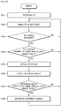
- FIG. 5 is a flowchart of operations of a smart device according to an embodiment of the present disclosure.
- a sensor device of the smart device detects movement of the smart device.
- the sensor device generates an interrupt signal corresponding to the movement in operation 520, and outputs the interrupt signal to a processor in operation 530.
- the processor in a low power mode receives the interrupt signal from the sensor device, and wakes up from the low power mode to a normal mode in response to the interrupt signal.
- the processor performs an action corresponding to the interrupt signal.
- the sensor device detects the movement of the smart device, but an embodiment is not limited thereto.
- a sensor included in the sensor device may not only be a sensor measuring movement of the smart device, but also a sensor measuring any value.
- the sensor included in the sensor device may be a sensor measuring biometric information.
- a sensor included in a wearable smart device worn by a user and measuring biometric information may detect biometric information of the user.
- a sensor device may transmit an interrupt signal to a processor and the processor may perform an action corresponding to the emergency upon receiving the interrupt signal.
- the action corresponding to the emergency may include, for example, transmitting a message to a hospital, an emergency medical treatment center, or a pre-set user.
- FIG. 6 illustrates examples of algorithms executed in a smart device according to an embodiment of the present disclosure.
- the algorithms include a core algorithm for a parent module and a child module for one or more sub-algorithms.
- the parent module tracks current accelerometer data 601, a rotation angle 603, a tilt angle 604, and pre-stored accelerometer historical data 605, according to a main cycle 602.
- the child module through child core 611 generates an interrupt signal by using the rotation angle 603 and the tilt angle 604 together with the pre-stored accelerometer historical data 605, in block 616.
- a register is updated to an identification (ID) of an algorithm that generated the interrupt signal and to an interrupt number.
- the child module may initialize the position in block 614, calculate history data in block 615, and evaluate a tilt angle when a change of the tilt angle 613 maintained in a pre-defined region for a pre-determined period of time is determined, in block 613.
- the child module may evaluate a rotation angle when a change of the rotation angle maintained in a pre-defined region for a pre-determined period of time is determined, in block 612.
- an accelerometer algorithm may be related to screen rotation of a smart device, a pedometer, free fall detection, shaking detection, or sharp turn detection, but is not limited thereto.
- a method of executing a group of accelerometer algorithms as a part of firmware of an accelerometer sensor chip may be provided.
- the parent module shares the rotation angle 603 and the tilt angle 604 with the child module.
- Accelerometer data in a child thread from a firmware loop is evaluated, and an enabled algorithm is executed.
- All algorithms executed in a hardware chip generate various interrupt signals based on respective events according to the algorithms.
- a plurality of child algorithms are executed together with a parent algorithm, and accelerometer activity is calculated by using sensor historical data, based on a current rotation angle and tilt angle.
- a generated interrupt signal is transmitted to an AP.
- FIG. 7 is a reference diagram for describing a tilt angle and a rotation angle according to an embodiment of the present disclosure.
- the tilt angle indicates a degree of tilt of a smart device relative to a certain reference position
- the rotation angle indicates by how much the smart device is rotated from the certain reference position.
- Tilt angle data of the smart device may be calculated based on a gravity component of one or more accelerometer sensors.
- Rotation angle data of the smart device may be calculated based on an X-axis value, a Y-axis value, and a Z-axis value of the accelerometer sensor.
- FIGS. 8A , 8B , and 8C are reference diagrams for describing a method of operating a smart device for turning on or off a functionality related to a motion sensor according to algorithms according to various embodiments of the present disclosure.
- FIG. 8A illustrates an example of a user interface of a smart device for turning on or off the functionality related to a motion sensor according to algorithms according to an embodiment of the present disclosure.
- a user may set the functionality to be turned on or off through the user interface 800.
- the user interface 800 may include menus for receiving on/off settings of the functionalities related to screen rotation 810, a pedometer 820, free fall 830, sharp turn 840, and shaking 850.
- the user may set a desired functionality to be turned on and an undesired functionality to be turned off from among the functionalities displayed on the user interface 800, thereby enabling/disabling the desired/ undesired functionalities.
- FIG. 8B is a diagram for describing a method of operating a smart device for turning on or off functionalities related to a motion sensor according to an embodiment of the present disclosure.
- an accelerometer sensor 860, a core algorithm 870, and sub-algorithms may be referred to as a sensor or a sensor device.
- the core algorithm 870 and the sub-algorithms may be integrated with a part of the accelerometer sensor 860 in a form of a circuit.
- Each of the core algorithm 870 and the sub-algorithms may be realized in a form of hardware, software, or firmware.
- the accelerometer sensor 860 may output a detected accelerometer sensor value to the core algorithm 870.
- the core algorithm 870 calculates a tilt angle and a rotation angle of the smart device based on the accelerometer sensor value, and output the tilt angle and the rotation angle to a sub-algorithm in an on-state.
- the sub-algorithms may include a screen rotation algorithm 811, a pedometer algorithm 821, a free fall algorithm 831, a sharp turn algorithm 841, and a shaking algorithm 851.
- Each of the sub-algorithms is an algorithm for triggering an interrupt signal for performing a certain function by using data detected by the accelerometer sensor 860.
- Each sub-algorithm may generate an interrupt signal by evaluating the rotation angle and the tilt angle by using a table 890.
- the screen rotation algorithm 811 may use a screen rotation table
- the pedometer algorithm 821 may use a pedometer table
- the free fall algorithm 831 may use a free fall table
- the sharp turn algorithm 841 may use a sharp turn table
- the shaking algorithm 851 may use a shaking table to evaluate the tilt angle and the rotation angle.
- FIG. 8C illustrates an example of a table according to an embodiment of the present disclosure.
- the table 890 may include tables used in the sub-algorithms.
- the screen rotation table may include a tilt angle table 891 and a rotation angle table 892.
- the tilt angle table 891 may be a table in which tilt angles of the smart device are divided according to ranges and certain values are pre-set according to ranges.
- the screen rotation algorithm 811 may output a range corresponding to a tilt angle to 0 when the tilt angle is 85.
- the rotation angle table 892 may be a table in which rotation angles of the smart device are divided according to ranges and certain values are pre-set according to ranges.
- the screen rotation algorithm 811 may output a range value corresponding to a rotation angle to 0 when the rotation angle is between +120 to +60.
- the ranges or values of the table 890 shown in FIG. 8C are only an example, and types, ranges, and range values of tables may be variously determined.
- a general accelerometer sensor that directly transmits measurement values, for example (X, Y, Z) coordinates, to a processor as raw data
- the processor receives movement coordinate values, i.e., the raw data, and processes movement information, and thus throughput and power consumption of the processor are high.
- a sensor value measured by a sensor is processed by the sensor to determine a movement range and only information about the movement range is transmitted to a processor, and thus throughput and power consumption of the processor may be decreased.
- Each of the sub-algorithms may be enabled or disabled by using the user interface shown in FIG. 8A .
- each sub-algorithm may be set to be enabled or disabled based on preference of the user.
- the screen rotation algorithm 811, the pedometer algorithm 821, and the shaking algorithm 851 may be set to be enabled, and the free fall algorithm 831 and the sharp turn algorithm 841 may be set to be disabled.
- One or more algorithms that are set to be enabled may simultaneously operate.
- the screen rotation algorithm 811, the pedometer algorithm 821, and the shaking algorithm 851 which are set to be enabled, receive the tilt angle and the rotation angle from the core algorithm 870, and evaluate the tilt angle and the rotation angle, so as to determine whether to generate an interrupt signal.
- One or more algorithms that generated an interrupt signal may transmit the interrupt signal to an AP 880.
- the user may select and enable only a desired sub-algorithm without having to simultaneously enable or disable all of the sub-algorithms, and thus power consumption may be decreased.
- FIG. 9 is a flowchart of a method of detecting screen rotation of a smart device according to an embodiment of the present disclosure.
- a position of the smart device is set to 0.
- a sensor device of the smart device executes an algorithm main cycle with wait is executed.
- the sensor device of the smart device determines whether a tilt angle of the smart device is changed. If there is no change, operation 920 is performed.
- the sensor device verifies the tilt angle by using an automatic rotation range table in operation 940 to determine whether the tilt angle is a valid tilt angle.
- the automatic rotation range table may include information about a degree of tilt (tilt angle) for determining whether an automatic rotation action satisfies a valid tilt angle.
- the sensor device updates the position of the smart device in operation 950.
- the sensor device checks a rotation angle.
- the sensor device verifies the rotation angle by using the automatic rotation range table to determine whether the rotation angle is a valid rotation angle.
- the automatic rotation range table may include information about a degree of rotation angle for determining a valid rotation angle.
- the sensor device When it is determined that the rotation angle is the valid rotation angle, the sensor device generates an interrupt signal in operation 980.
- the sensor device transmits the interrupt signal to a processor to wake up the processor.
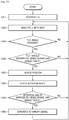
- FIG. 10 is a flowchart of a method of detecting a position of an arm lifted and holding a smart device according to an embodiment of the present disclosure.
- a position of the smart device is set to 0 in operation 1010.
- a sensor device of the smart device executes an algorithm main cycle with wait.
- the sensor device of the smart device determines whether a tilt angle of the smart device changed. If there is no change, operation 1020 is performed.
- the sensor device verifies the tilt angle by using an ARM_UP_HOLD range table in operation 1040 to determine whether the tilt angle is a valid tilt angle.
- the ARM_UP_HOLD range table may include information about a degree of tilt (tilt angle) of the smart device for determining whether an action of lifting an arm satisfies a valid tilt angle.
- the sensor device updates the position of the smart device in operation 1050.
- the sensor device checks a rotation angle.
- the sensor device verifies the rotation angle by using the ARM_UP_HOLD range table to determine whether the rotation angle is a valid rotation angle. When it is determined that the rotation table is not the valid rotation table, operation 1020 is performed.
- the sensor device When it is determined that the rotation angle is the valid rotation angle, the sensor device generates an interrupt signal in operation 1080.
- the sensor device transmits the interrupt signal to a processor so as to wake up the processor.
- a processor of the wearable watch device when an arm of user wearing a wearable watch device on a wrist is naturally hanging down, a processor of the wearable watch device is in a standby mode.
- a sensor device of the wearable watch device detects movement of the arm and wakes up the processor accordingly.
- the processor may perform one or more actions corresponding to the movement of the arm.
- the one or more actions may include, for example, displaying basic information to the user by converting a display of the wearable watch device to a normal mode and displaying a user interface for receiving an input from the user.
- a wakeup call is performed when a user looks at a watch in a natural gesture while the watch is in a low power mode, and thus an on/off delay of an arbitrary wearable device (for example, a smart watch) is avoided, and an interrupt signal for turning on or off the arbitrary wearable device may be generated.
- an arbitrary wearable device for example, a smart watch
- FIG. 11 is a flowchart of a method of detecting a free fall of a user carrying a smart device according to an embodiment of the present disclosure.
- a position of a smart device is set to 0.
- a sensor device of the smart device executes an algorithm main cycle with wait.
- the sensor device of the smart device determines whether a tilt angle of the smart device is changed. If there is no change, operation 1120 is performed.
- the sensor device verifies the tilt angle by using a Free_Fall range table in operation 1140 to determine whether the tilt angle is a valid tilt angle.
- the Free_Fall range table may include information about a degree of tilt (tilt angle) of the smart device for determining whether a free fall action satisfies a valid tilt angle.
- the sensor device updates the position of the smart device in operation 1150.
- the sensor device checks a rotation angle.
- the sensor device verifies the rotation angle by using the Free_Fall range table in operation 1170 to determine whether the rotation angle is a valid rotation angle. When it is determined that the rotation angle is not the valid rotation angle, operation 1120 is performed.
- the sensor device When it is determined that the rotation angle is the valid rotation angle, the sensor device generates an interrupt signal in operation 1180.
- the sensor device transmits the interrupt signal to a processor to wake up the processor.
- an interrupt signal may be transmitted to a processor of the smart phone by detecting a user suddenly falling.
- the processor wakes up to a normal mode according to the interrupt signal from the sensor device, and may provide a real-time alert by performing one or more actions corresponding to movement of the user, for example, by making a sound or transmitting an alert message to a pre-assigned phone number.
- power consumption is low, an interrupt signal is generated based on an emergency of falling, and it is determined whether to alert a user, transmit a message to a pre-assigned phone number, or to transmit an alert to an emergency phone number.
- the method may be used for senior citizens.
- FIG. 12 is a flowchart of a method of counting a number of steps of a user wearing a smart device including a pedometer according to an embodiment of the present disclosure.
- a position of a smart device is set to 0.
- a sensor device of the smart device executes an algorithm main cycle with wait.
- the sensor device of the smart device determines whether a tilt angle of the smart device is changed. If there is no change, operation 1220 is performed.
- the sensor device verifies the tilt angle by using a PEDO_COUNT range table in operation 1240 to determine whether the tilt angle is a valid tilt angle.
- the PEDO_COUNT range table may include information about a degree of tilt (tilt angle) of the smart device for determining whether a pedometer action satisfies a valid tilt angle.
- the sensor device updates the position of the smart device in operation 1250.
- the sensor device checks a rotation angle.
- the sensor device verifies the rotation angle by using the PEDO_COUNT range table to determine whether the rotation angle is a valid rotation angle. When it is determined that the rotation angle is not the valid rotation angle, operation 1220 is performed.
- the sensor device When it is determined that the rotation angle is the valid rotation angle, the sensor device generates an interrupt signal in operation 1280.
- the sensor device transmits the interrupt signal to a processor to wake up the processor.
- the sensor device of the smart device counts and stores the number of steps of the user even when the smart device or the processor is in a standby mode, and may alert the user by transmitting the interrupt signal to the processor at uniform intervals after or without being woken up from a low power mode.
- an interrupt signal may be detected and generated at certain time frames, and a user may be notified with the number of steps without having to use a sensor hub or a separate microprocessor.
- FIG. 13 is a flowchart of a method of detecting shaking of a smart device according to an embodiment of the present disclosure.
- a position of a smart device is set to 0.
- a sensor device of the smart device executes an algorithm main cycle with wait.
- the sensor device of the smart device determines whether a tilt angle of the smart device is changed. If there is no change, operation 1320 is performed.
- the sensor device verifies the tilt angle by using a SHAKE_VAR range table in operation 1340 to determine whether the tilt angle is a valid tilt angle.
- the SHAKE_VAR range table may include information about a degree of tilt (tilt angle) of the smart device for determining whether a shaking action satisfies a valid tilt angle.
- the sensor device updates the position of the smart device in operation 1350.
- the sensor device checks a rotation angle.
- the sensor device verifies the rotation angle by using the SHAKE_VAR range table in operation 1370 to determine whether the rotation angle is a valid rotation angle. When it is determined that the rotation angle is not the valid rotation angle, operation 1320 is performed.
- the sensor device When it is determined that the rotation angle is the valid rotation angle, the sensor device generates an interrupt signal in operation 1380.
- the sensor device transmits the interrupt signal to a processor to wake up the processor.
- the sensor device of the smart device detects when the user shakes the smart device while the smart device is in a standby mode, generates the interrupt signal based on strength of the shaking, and wakes up the processor.
- a shaking detection alert may be provided even when the smart device is in a sleep mode using low power consumption.
- FIG. 14 is a flowchart of a method of detecting a sharp turn of a user wearing a smart device according to an embodiment of the present disclosure.
- a position of the smart device is set to 0 in operation 1410.
- a sensor device of the smart device executes an algorithm main cycle with wait.
- the sensor device of the smart device determines whether a tilt angle of the smart device is changed. If there is no change, operation 1420 is performed.
- the sensor device verifies the tilt angle by using a SHARP_TURN range table in operation 1440 to determine whether the tilt angle is a valid tilt angle.
- the SHARP_TURN range table may include information about a degree of tilt (tilt angle) for determining whether a sharp turn action satisfies a valid tilt angle.
- the sensor device updates the position of the smart device in operation 1450.
- the sensor device checks a rotation angle.
- the sensor device verifies the rotation angle by using the SHARP_TURN range table in operation 1470 to determine whether the rotation angle is a valid rotation angle. When it is determined that the rotation angle is not the valid rotation angle, operation 1420 is performed.
- the sensor device When it is determined that the rotation angle is the valid rotation angle, the sensor device generates an interrupt signal in operation 1480.
- the sensor device transmits the interrupt signal to a processor to wake up the processor.
- the sensor device of the smart device may detect a sharp turn of the smart device while the user is walking or in a car, even when the smart device is in a low power mode.
- the sensor device when the sensor device detects the sharp turn of the smart device while the user is sleeping, walking, or moving in a car, the sensor device transmits an interrupt signal to the processor and the processor may perform at least one action corresponding to the sharp turn.
- the at least one action may include alerting a pregnant women or transmitting an alert message to an emergency phone number or 911.
- a decision making delay is avoided, and specifically, a method of providing a real-time high-speed response in a decision making situation where time is very important may be achieved.
- processing in an AP is removed, and by reducing space and operation complexity, power consumption may be reduced and performance of a smart device may be increased.
- One or more embodiments of the present disclosure do not require an additional hardware block or a microprocessor that requires high processing. Also, a power number of a microprocessor may be relatively decreased compared to another microprocessor, without capability deterioration.
- the methods described above may be recorded on a non-transitory computer-readable recording medium by being realized in computer programs executed by using various computers.
- the non-transitory computer-readable recording medium may include at least one of a program command, a data file, and a data structure.
- the program commands recorded in the non-transitory computer-readable recording medium may be specially designed or well known to one of ordinary skill in the computer software field. Examples of the non-transitory computer-readable recording medium include ROM, RAM, compact disc (CD)-ROMs, magnetic tapes, floppy disks, optical data storage devices, etc. Examples of the computer command include mechanical codes prepared by a compiler, and high-level languages executable by a computer by using an interpreter.
Description
- The present disclosure relates to electronic apparatuses and methods of operating the same. More particularly, the present disclosure relates to an electronic apparatus for displaying a graphic user interface (GUI) element, and a method of operating the electronic apparatus.
- An accelerometer sensor is one of commonly used motion sensors and is used in various solutions, such as for a pedometer, screen rotation, automatic brightness, and free fall detection. Algorithms in all such cases require accelerometer data to be polled not only at 100 Hz, but also at 5 Hz, 16 Hz, and 50 Hz.
- A device having a sensor operates using the following two methods.
- First, a sensor is connected to an application processor (AP). The AP is in a wake up state to receive data and periodically polls the sensor.
- Second, a sensor is connected to a microcontroller (MCU, i.e., a sensor hub). An AP may sleep and the MCU may be sleepwalking. Processing may occur in the MCU, and the MCU may wake up the AP when necessary. Here, the MCU periodically polls the sensor.
- A major disadvantage of such a polling method is that a system requires uninterrupted polling of accelerometer data either from an AP or from an MCU. As a result, there is a possibility that battery performance may largely deteriorate because such a polling method requires a huge amount of processing and continuous polling with respect to a sensor and the sensor needs to operate in a normal mode. Latency in data is another big problem in an MCU-based method. Accelerometer data may be available to an upper layer through a polling mechanism and is used in the upper layer for decision making for all algorithms. Due to the polling mechanism and complex decision making processes accompanied by mathematical operations or signal processing, sluggish behavior may be generated, and thus it may be impossible to receive real-time responses.
- In existing architecture, accelerometer data is transmitted to an application layer by using a polling mechanism. Such an operation is intensive for a central processing unit (CPU), and thus a data receiving rate is reduced. Most applications access data by using the polling mechanism. In other words, the data is processed in an uppermost layer and then necessary actions to be taken are determined according to algorithms. Accordingly, a possibility of a high-speed response is reduced in cases where a fall is detected. Due to the polling mechanism, CPU million instructions per second (MIPS) are wasted and thus power consumption is increased.
US2014/0059365A1 discloses an apparatus having an interrupt sensor for waking up a main processor.EP2317744A1 discloses a system for activating an electronic device comprising a motion detection circuit.EP2683204A1 discloses a method for controlling a sleep mode in a portable terminal. - Accordingly, there is a need for a method for a high-speed dynamic response of a smart device, which provides an instant alert and does not require a polling mechanism.
- The above information is presented as background information only to assist with an understanding of the present disclosure. No determination has been made, and no assertion is made, as to whether any of the above might be applicable as prior art with regard to the present disclosure.
- Aspects of the present disclosure are to address at least the above-mentioned problems and/or disadvantages and to provide at least the advantages described below. Accordingly, an aspect of the present disclosure is to provide a smart device for reducing power consumption and enabling a fast response, and a method of operating the smart device. The invention is defined by the independent claims. Further aspects of the invention are outlined in the dependent claims. In the following, if the term "embodiment" relates to unclaimed combinations of features, said term has to be understood as referring to non-claimed matter considered to be useful for highlighting specific aspects of the claimed subject-matter.
- Additional aspects will be set forth in part in the description which follows and, in part, will be apparent from the description, or may be learned by practice of the presented embodiments.
- According to embodiments described above, a decision making delay is avoided, and specifically, a method of providing a real-time high-speed response in a decision making situation where time is very important may be achieved. By avoiding polling of accelerometer data, processing in an AP is removed, and by reducing space and operation complexity, power consumption may be reduced and performance of a smart device may be increased. One or more embodiments of the present disclosure do not require an additional hardware block or a microprocessor that requires high processing. Also, a power number of a microprocessor may be relatively decreased compared to another microprocessor, without capability deterioration.
- The above and other aspects, features, and advantages of certain embodiments of the present disclosure will be more apparent from the following description taken in conjunction with the accompanying drawings, in which:
-
FIG. 1 is a reference diagram of an example for describing a concept according to an embodiment of the present disclosure; -
FIG. 2 is a reference diagram of another example for describing a concept according to an embodiment of the present disclosure; -
FIG. 3 is a block diagram of a smart device according to an embodiment of the present disclosure; -
FIG. 4 is a block diagram illustrating in detail a sensor device ofFIG. 3 according to an embodiment of the present disclosure; -
FIG. 5 is a flowchart of operations of a smart device according to an embodiment of the present disclosure; -
FIG. 6 illustrates examples of algorithms executed in a smart device according to an embodiment of the present disclosure; -
FIG. 7 is a reference diagram for describing a tilt angle and a rotation angle according to an embodiment of the present disclosure; -
FIGS. 8A ,8B , and8C are reference diagrams for describing a method of operating a smart device for turning on or off a functionality related to a motion sensor according to algorithms according to various embodiments of the present disclosure; -
FIG. 9 is a flowchart of a method of detecting screen rotation of a smart device according to an embodiment of the present disclosure; -
FIG. 10 is a flowchart of a method of detecting a position of an arm lifted and holding a smart device according to an embodiment of the present disclosure; -
FIG. 11 is a flowchart of a method of detecting a free fall of a user carrying a smart device according to an embodiment of the present disclosure; -
FIG. 12 is a flowchart of a method of counting the number of steps of a user wearing a smart device including a pedometer according to an embodiment of the present disclosure; -
FIG. 13 is a flowchart of a method of detecting shaking of a smart device according to an embodiment of the present disclosure; and -
FIG. 14 is a flowchart of a method of detecting a sharp turn of a user wearing a smart device according to an embodiment of the present disclosure. - Throughout the drawings, it should be noted that like reference numbers are used to depict the same or similar elements, features, and structures.
- In accordance with an aspect of the present disclosure, a smart device is provided. The smart device includes a processor, and a sensor configured to detect movement of the smart device, generate an interrupt signal including information on a movement range corresponding to at least one movement type determined based on the detected movement, and output the interrupt signal to the processor and the processor is configured to control an action, corresponding to the interrupt signal received from the sensor, to be performed in response to the interrupt signal.
- The information on the movement range included in the interrupt signal may include at least one of an identifier indicating the at least one movement type, or a value indicating the movement range corresponding to a direction or magnitude of the movement.
- The sensor may include one or more algorithms, and may be configured to determine each of the at least one movement type, in which the one or more algorithms may each be settable to be enabled or disabled.
- The one or more algorithms may each be settable to be enabled or disabled according to a user setting received from a user interface.
- The processor may be further configured to wake up from a low power mode to a normal mode in response to the interrupt signal received from the sensor.
- The sensor may be further configured to calculate at least one of a tilt angle or a rotation angle of the smart device based on sensing data from detecting the movement of the smart device, evaluate at least one of the tilt angle or the rotation angle based on at least one of a rotation angle table or a tilt angle table, which is pre-stored, and generate the interrupt signal including the information on the movement range based on a result of an evaluation.
- The rotation angle table may include a range value corresponding to the rotation angle, and the tilt angle table may include a range value corresponding to the tilt angle.
- In accordance with another aspect of the present disclosure, a method of operating a smart device is provided. The method includes detecting, by a sensor, movement of the smart device, generating an interrupt signal including information on a movement range corresponding to at least one movement type determined based on the movement, outputting the interrupt signal to a processor and controlling, by the processor, an action, corresponding to the interrupt signal, to be performed in response to the interrupt signal received from the sensor.
- According to an aspect of another embodiment, a non-transitory computer-readable recording medium has recorded thereon a program code for executing the method.
- Other aspects, advantages, and salient features of the disclosure will become apparent to those skilled in the art from the following detailed description, which, taken in conjunction with the annexed drawings, discloses various embodiments of the present disclosure.
- The following description with reference to the accompanying drawings is provided to assist in a comprehensive understanding of various embodiments of the present disclosure as defined by the claims. It includes various specific details to assist in that understanding but these are to be regarded as merely exemplary. Accordingly, those of ordinary skill in the art will recognize that various changes and modifications of the various embodiments described herein can be made without departing from the scope of the present disclosure. In addition, descriptions of well-known functions and constructions may be omitted for clarity and conciseness.
- The terms and words used in the following description and claims are not limited to the bibliographical meanings, but, are merely used by the inventor to enable a clear and consistent understanding of the present disclosure. Accordingly, it should be apparent to those skilled in the art that the following description of various embodiments of the present disclosure is provided for illustration purpose only and not for the purpose of limiting the present disclosure as defined by the appended claims.
- It is to be understood that the singular forms "a," "an," and "the" include plural referents unless the context clearly dictates otherwise. Thus, for example, reference to "a component surface" includes reference to one or more of such surfaces.
- While such terms as "first", "second", etc., may be used to describe various components, such components must not be limited to the above terms. The above terms are used only to distinguish one component from another. For example, a first component may be referred to as a second component, and similarly, a second component may be referred to as a first component while not departing from the scope of the present disclosure. As used herein, the term "and/or" includes any and all combinations of one or more of the associated listed items. Expressions such as "at least one of", when preceding a list of elements, modify the entire list of elements and do not modify the individual elements of the list.
- In the present specification, it is to be understood that terms such as "including" or "having", etc., are intended to indicate the existence of the features, numbers, operations, actions, components, parts, or combinations thereof disclosed in the specification, and are not intended to preclude the possibility that one or more other features, numbers, operations, actions, components, parts, or combinations thereof may exist or may be added.
- Hereinafter, embodiments will now be described with reference to accompanying drawings.
-
FIG. 1 is a reference diagram of an example for describing a concept according to an embodiment of the present disclosure. - Referring to
FIG. 1 , asmart device 100 according to an embodiment includessensor devices 110 through 130, and aprocessor 140. - The
smart device 100 may include one or more sensor devices. InFIG. 1 , for example, threesensor devices 110 through 130 are shown, but the number of sensor devices may be one or more. - The
sensor devices 110 through 130 may include a sensor for detecting movement of thesmart device 100, and a small scale processor or small scale circuit for generating and processing an interrupt signal. In the present specification, a sensor device including a sensor and a small scale processor or small scale circuit may also be simply referred to as a sensor. - At least one of the
sensor devices 110 through 130 may detect movement of thesmart device 100, generate an interrupt signal corresponding to the movement, and transmit the interrupt signal to theprocessor 140. - According to an embodiment, at least one of the
sensor devices 110 through 130 may detect the movement of thesmart device 100, and generate an interrupt signal including information on a movement range corresponding to at least one movement type determined based on the movement. - According to an embodiment, the information on the movement range included in the interrupt signal may include at least one of an identifier including the movement type, and a value indicating the movement range corresponding to a direction or magnitude of the movement.
- According to an embodiment, each of the
sensor devices 110 through 130 includes one or more modules determining each movement type, and the one or more modules may each be set to be enabled or disabled. Also, the one or more modules may each be set to be enabled or disabled according to a user setting received from a user interface. - According to an embodiment, each of the
sensor devices 110 through 130 may calculate at least one of a tilt angle and a rotation angle of thesmart device 100 based on sensing data from detecting the movement of thesmart device 100, evaluate at least one of the tilt angle and the rotation angle based on at least one of a rotation angle table and a tilt angle table, which is pre-stored, and generate the interrupt signal including the information on the movement range based on a result of the evaluation. - According to an embodiment, the rotation angle table may include a range value corresponding to one or more rotation angles, and the tilt angle table may include a range value corresponding to one or more tilt angles.
- The
processor 140 processes overall operations of thesmart device 100, wherein theprocessor 140 may receive an interrupt signal from at least one of thesensor devices 110 through 130 while theprocessor 140 is in a low power mode, and wake up from the low power mode to a normal mode in response to the interrupt signal. Also, theprocessor 140 may perform one or more actions corresponding to the interrupt signal. - The one or more actions corresponding to the interrupt signal may include, for example, displaying of a certain message or a certain user interface on a display, outputting of a certain alarm, and transmitting of a notification to a certain destination, and may include any action performable by using a module included in the
smart device 100. - The
processor 140 may include an application processor (AP). - According to a structure shown in
FIG. 1 , unlike a general processor that is in a wake up state to poll a sensor to periodically detect movement, at least one of thesensor devices 110 through 130 actively wakes up theprocessor 140 in a low power mode when movement is detected, and thus power consumption of theprocessor 140 is reduced and a load of theprocessor 140 that is generally always polling may be reduced. - The
smart device 100 according to various embodiments may be a device having a communication function. For example, thesmart device 100 may include at least one of a smart phone, a tablet personal computer (PC), a mobile phone, a video phone, an e-book reader, a desktop PC, a laptop PC, a netbook computer, a personal digital assistant (PDA), a portable multimedia player (PMP), a Moving PictureExperts Group phase 1 or phase 2 (MPEG-1 or MPEG-2) audio layer 3 (MP3) player, a mobile medical device, a camera, and a wearable device (for example, a head-mounted device (HMD) like electronic glasses, an electronic dress, an electronic bracelet, an electronic necklace, an electronic accessory, an electronic tattoo, or a smart watch). - The
smart device 100 according to various embodiments may be one of various devices described above, or a combination thereof. Also, thesmart device 100 according to various embodiments may be a flexible device. Also, it would be obvious to one of ordinary skill in the art that thesmart device 100 according to various embodiments is not limited to the above devices. -
FIG. 2 is a reference diagram of another example for describing a concept according to an embodiment of the present disclosure. - Referring to
FIG. 2 , asmart device 200 according to an embodiment includessensor devices 210 through 230, asensor hub 240, and aprocessor 250. - The
sensor devices 210 through 230 and theprocessor 250 perform the same operations as those shown inFIG. 1 , and a difference between thesmart device 100 ofFIG. 1 and thesmart device 200 ofFIG. 2 is that thesmart device 200 further includes thesensor hub 240. - The
sensor hub 240 is also referred to as a sensor sub-system, and manages thesensor devices 210 through 230. - The
sensor hub 240 may wake up and enter into a normal mode upon receiving an interrupt signal from at least one of thesensor devices 210 through 230 while thesensor hub 240 is in a low power mode, manage the interrupt signal, and transmit the interrupt signal to theprocessor 250 in a low power mode. Theprocessor 250 may wake up from the low power mode upon receiving the interrupt signal from thesensor hub 240, and perform one or more actions corresponding to the interrupt signal. -
FIG. 3 is a block diagram of asmart device 300 according to an embodiment of the present disclosure. - Referring to
FIG. 3 , a smart device according to an embodiment includes asensor device 310, anAP 320, amemory 330, acommunication interface 340, adisplay 350, an audio input andoutput interface 360, an input andoutput interface 370, and apower supply 380. - The
sensor device 310 may measure a physical quantity or detect an operation state of thesmart device 300, and convert measured or detected information to an electric signal. Thesensor device 310 may include, for example, at least one of a gesture sensor, a gyro sensor, an atmospheric sensor, a magnetic sensor, an acceleration sensor, a grip sensor, a proximity sensor, a color sensor, a biometric sensor, a temperature/humidity sensor, an illumination sensor, and an ultraviolet (UV) sensor. In addition or alternatively, thesensor device 310 may include, for example, an e-nose sensor, an electromyography (EMG) sensor, an electroencephalogram (EEG) sensor, an electrocardiogram (ECG) sensor, an infrared ray (IR) sensor, an iris sensor, or a fingerprint sensor. - According to an embodiment, the
sensor device 310 may further include a control circuit for controlling at least one sensor included in thesensor device 310. - According to an embodiment, the
sensor device 310 may measure the physical quantity of thesmart device 300 even in a lower power mode of thesmart device 300, generate an interrupt signal according to the measurement, and transmit the interrupt signal to theAP 320 in a low power mode. - According to an embodiment, the
sensor device 310 may detect a tilt angle or a rotation angle of thesmart device 300. - The
AP 320 may, for example, receive a command from another component described above (for example, thememory 330, the input andoutput interface 370, thedisplay 350, or the communication interface 340) through abus 390, decode the command, and perform a data process or an operation according to the command. - The
AP 320 may control a plurality of hardware or software components connected to theAP 320 by driving an operating system (OS) or an application program, and perform various data processes and operations including multimedia data. TheAP 320 may be, for example, realized as a system-on-chip (SoC). According to an embodiment, theAP 320 may further include a graphics processing unit (GPU). - According to an embodiment, the
AP 320 may receive an interrupt signal from thesensor device 310 while theAP 320 is in a low power mode, and wake up from the low power mode to a normal mode in response to the interrupt signal. Also, theAP 320 may perform one or more actions corresponding to the interrupt signal, in response to the interrupt signal. The one or more actions performed by theAP 320 according to the interrupt signal may be stored in thememory 330. - The one or more actions may include, for example, transmitting a notification to another device through the
communication interface 340, turning on thedisplay 350 and outputting a certain message or a certain user interface to thedisplay 350, turning on the audio input andoutput interface 360 and outputting a certain sound, and inputting and outputting data by using the input andoutput interface 370. - The
memory 330 may store a command or data received from or generated by theAP 320 or another component (for example, the input andoutput interface 370, thedisplay 350, or the communication interface 340). Thememory 330 may include, for example, program modules, such as a kernel, middleware, an application programming interface (API), and an application. Each programming module may include software, firmware, hardware, or a combination thereof. Thememory 330 may include an internal memory or an external memory. The internal memory may include, for example, at least one of a volatile memory (for example, a dynamic random access memory (DRAM), a static RAM (SRAM), or a synchronous DRAM (SDRAM)), and a non-volatile memory (for example, a one-time programmable read-only memory (OTPROM), a programmable ROM (PROM), an erasable and programmable ROM (EPROM), an electrically erasable and programmable ROM (EEPROM), a mask ROM, a flash ROM, a NAND flash memory, or a NOR flash memory). - According to an embodiment, the external memory may include a flash drive, and may further include, for example, a compact flash (CF) card, a secure digital (SD) card, a micro-SD card, a mini-SD card, an extreme digital (xD) card, or a memory stick.
- According to an embodiment, the
memory 330 may include a table in which a plurality of interrupt signals and one or more actions performed according to an interrupt signal are mapped and defined. - The
communication interface 340 may connect thesmart device 300 and an external apparatus for communication. For example, thecommunication interface 340 may be connected to a network through wireless communication or wired communication to communicate with the external apparatus. The wireless communication may include, for example, at least one of Wi-Fi, Bluetooth (BT), near field communication (NFC), global positioning system (GPS), and cellular communication (for example, long-term evolution (LTE), LTE-advanced (LTE-A), code division multiple access (CDMA), wideband CDMA (WCDMA), universal mobile telephone system (UMTS), wireless broadband (WiBro), or global system for mobile communication (GSM)). The wired communication may include, for example, at least one of universal serial bus (USB), high-definition multimedia interface (HDMI), recommended standard 232 (RS-232), and plain old telephone service (POTS). - The
display 350 may display various types of information (for example, multimedia data or text data) for a user. - The audio input and
output interface 360 may convert sound and an electric signal in bi-directions, and for example, process sound information input or output through, for example, a speaker, a receiver, an earphone, or a microphone. - The input and
output interface 370 may transmit a command or data input by the user through an input and output device (for example, a sensor, a keyboard, or a touch screen) to, for example, theAP 320, thememory 330, or thecommunication interface 340 through thebus 390. - The
power supply 380 may manage power of thesmart device 300. Although not illustrated, thepower supply 380 may include, for example, a power management integrated circuit (PMIC), a charger IC, or a battery or fuel gauge. - The
bus 390 may be a circuit that connects the above components to each other and transfer a communication (for example, a control message) between the components. - Each of the components of the
smart device 300 according to various embodiments may include one or more parts, and a name of component may vary according to types of thesmart device 300. Thesmart device 300 according to various embodiments may include at least one of the above components, and may include more or less components than those shown inFIG. 3 . Also, some of the components of thesmart device 300 according to various embodiments may be combined to form one entity and perform functions of some components that are combined. -
FIG. 4 is a block diagram illustrating in detail a sensor device ofFIG. 3 according to an embodiment of the present disclosure. - Referring to
FIG. 4 , thesensor device 310 includes asensor 311, a digital signal processor (DSP) 312, atimer 313, and one ormore registers 314. - The
sensor 311 detects movement of thesmart device 300 or a physical quantity of thesmart device 300. - The
DSP 312 receives detection data from thesensor 311, determines whether the detection data is valid to generate an interrupt signal by using thetimer 313, generates the interrupt signal based on a result of the determination, and stores the interrupt signal in theregister 314. - For example, an interrupt signal may be stored in two registers. From among the two registers, an algorithm identifier may be stored in a first register and an interrupt state may be stored in a second register. The interrupt state may include, for example, a value related to a pre-set algorithm for a pre-defined action including, but not limited to, screen rotation of a smart device, a pedometer, free fall detection, shaking detection, or sharp turn detection. The interrupt signal includes meaningful results and no further processing is required for making decisions.
- For example, the algorithm identifier stored in the first register may indicate auto rotation, and the interrupt state stored in the second register may include a value indicating a direction of rotation.
- For example, the algorithm identifier stored in the first register may indicate a pedometer and the interrupt state stored in the second register may include a value indicating the number of steps.
-
FIG. 5 is a flowchart of operations of a smart device according to an embodiment of the present disclosure. - Referring to
FIG. 5 , inoperation 510, a sensor device of the smart device detects movement of the smart device. - The sensor device generates an interrupt signal corresponding to the movement in
operation 520, and outputs the interrupt signal to a processor inoperation 530. - In
operation 540, the processor in a low power mode receives the interrupt signal from the sensor device, and wakes up from the low power mode to a normal mode in response to the interrupt signal. - In
operation 550, the processor performs an action corresponding to the interrupt signal. - In the operations of
FIG. 5 , the sensor device detects the movement of the smart device, but an embodiment is not limited thereto. A sensor included in the sensor device may not only be a sensor measuring movement of the smart device, but also a sensor measuring any value. For example, the sensor included in the sensor device may be a sensor measuring biometric information. For example, a sensor included in a wearable smart device worn by a user and measuring biometric information may detect biometric information of the user. Here, when the biometric information of the user indicates an emergency, a sensor device may transmit an interrupt signal to a processor and the processor may perform an action corresponding to the emergency upon receiving the interrupt signal. The action corresponding to the emergency may include, for example, transmitting a message to a hospital, an emergency medical treatment center, or a pre-set user. -
FIG. 6 illustrates examples of algorithms executed in a smart device according to an embodiment of the present disclosure. - Referring to
FIG. 6 , the algorithms according to an embodiment include a core algorithm for a parent module and a child module for one or more sub-algorithms. The parent module trackscurrent accelerometer data 601, arotation angle 603, atilt angle 604, and pre-stored accelerometerhistorical data 605, according to amain cycle 602. - The child module through
child core 611 generates an interrupt signal by using therotation angle 603 and thetilt angle 604 together with the pre-stored accelerometerhistorical data 605, inblock 616. When the interruptsignal 615 is generated, a register is updated to an identification (ID) of an algorithm that generated the interrupt signal and to an interrupt number. - The child module may initialize the position in
block 614, calculate history data inblock 615, and evaluate a tilt angle when a change of thetilt angle 613 maintained in a pre-defined region for a pre-determined period of time is determined, inblock 613. - The child module may evaluate a rotation angle when a change of the rotation angle maintained in a pre-defined region for a pre-determined period of time is determined, in
block 612. - According to an embodiment, an accelerometer algorithm may be related to screen rotation of a smart device, a pedometer, free fall detection, shaking detection, or sharp turn detection, but is not limited thereto.
- According to an embodiment, a method of executing a group of accelerometer algorithms as a part of firmware of an accelerometer sensor chip may be provided. When the
rotation angle 603 and thetilt angle 604 are identified and a request is received from the child module, the parent module shares therotation angle 603 and thetilt angle 604 with the child module. Accelerometer data in a child thread from a firmware loop is evaluated, and an enabled algorithm is executed. All algorithms executed in a hardware chip generate various interrupt signals based on respective events according to the algorithms. Also, a plurality of child algorithms are executed together with a parent algorithm, and accelerometer activity is calculated by using sensor historical data, based on a current rotation angle and tilt angle. A generated interrupt signal is transmitted to an AP. -
FIG. 7 is a reference diagram for describing a tilt angle and a rotation angle according to an embodiment of the present disclosure. - Referring to
FIG. 7 , the tilt angle indicates a degree of tilt of a smart device relative to a certain reference position, and the rotation angle indicates by how much the smart device is rotated from the certain reference position. When the rotation or tilt angle of the smart device is detected, the rotation or tilt angle is verified to check if it is valid. When it is determined that the rotation or tilt angle is valid, an interrupt signal is generated based on an executed algorithm and an occurred event. - Tilt angle data of the smart device may be calculated based on a gravity component of one or more accelerometer sensors.
- Rotation angle data of the smart device may be calculated based on an X-axis value, a Y-axis value, and a Z-axis value of the accelerometer sensor.
-
FIGS. 8A ,8B , and8C are reference diagrams for describing a method of operating a smart device for turning on or off a functionality related to a motion sensor according to algorithms according to various embodiments of the present disclosure. -
FIG. 8A illustrates an example of a user interface of a smart device for turning on or off the functionality related to a motion sensor according to algorithms according to an embodiment of the present disclosure. - A user may set the functionality to be turned on or off through the
user interface 800. - Referring to
FIG. 8A , theuser interface 800 may include menus for receiving on/off settings of the functionalities related toscreen rotation 810, apedometer 820,free fall 830,sharp turn 840, and shaking 850. The user may set a desired functionality to be turned on and an undesired functionality to be turned off from among the functionalities displayed on theuser interface 800, thereby enabling/disabling the desired/ undesired functionalities. -
FIG. 8B is a diagram for describing a method of operating a smart device for turning on or off functionalities related to a motion sensor according to an embodiment of the present disclosure. - Referring to
FIG. 8B , anaccelerometer sensor 860, acore algorithm 870, and sub-algorithms may be referred to as a sensor or a sensor device. For example, thecore algorithm 870 and the sub-algorithms may be integrated with a part of theaccelerometer sensor 860 in a form of a circuit. Each of thecore algorithm 870 and the sub-algorithms may be realized in a form of hardware, software, or firmware. - Referring to
FIG. 8B , theaccelerometer sensor 860 may output a detected accelerometer sensor value to thecore algorithm 870. Thecore algorithm 870 calculates a tilt angle and a rotation angle of the smart device based on the accelerometer sensor value, and output the tilt angle and the rotation angle to a sub-algorithm in an on-state. - The sub-algorithms may include a
screen rotation algorithm 811, apedometer algorithm 821, afree fall algorithm 831, asharp turn algorithm 841, and a shakingalgorithm 851. Each of the sub-algorithms is an algorithm for triggering an interrupt signal for performing a certain function by using data detected by theaccelerometer sensor 860. Each sub-algorithm may generate an interrupt signal by evaluating the rotation angle and the tilt angle by using a table 890. Thescreen rotation algorithm 811 may use a screen rotation table, thepedometer algorithm 821 may use a pedometer table, thefree fall algorithm 831 may use a free fall table, thesharp turn algorithm 841 may use a sharp turn table, and the shakingalgorithm 851 may use a shaking table to evaluate the tilt angle and the rotation angle. -
FIG. 8C illustrates an example of a table according to an embodiment of the present disclosure. - Referring to
FIG. 8C , the table 890 may include tables used in the sub-algorithms. For example, the screen rotation table may include a tilt angle table 891 and a rotation angle table 892. - The tilt angle table 891 may be a table in which tilt angles of the smart device are divided according to ranges and certain values are pre-set according to ranges. For example, the
screen rotation algorithm 811 may output a range corresponding to a tilt angle to 0 when the tilt angle is 85. - The rotation angle table 892 may be a table in which rotation angles of the smart device are divided according to ranges and certain values are pre-set according to ranges. For example, the
screen rotation algorithm 811 may output a range value corresponding to a rotation angle to 0 when the rotation angle is between +120 to +60. - The ranges or values of the table 890 shown in
FIG. 8C are only an example, and types, ranges, and range values of tables may be variously determined. - In an example of a general accelerometer sensor that directly transmits measurement values, for example (X, Y, Z) coordinates, to a processor as raw data, the processor receives movement coordinate values, i.e., the raw data, and processes movement information, and thus throughput and power consumption of the processor are high. However, according to the embodiment shown in
FIGS. 8B and8C , a sensor value measured by a sensor is processed by the sensor to determine a movement range and only information about the movement range is transmitted to a processor, and thus throughput and power consumption of the processor may be decreased. - Each of the sub-algorithms may be enabled or disabled by using the user interface shown in
FIG. 8A . In other words, each sub-algorithm may be set to be enabled or disabled based on preference of the user. As shown in the user interface ofFIG. 8A , thescreen rotation algorithm 811, thepedometer algorithm 821, and the shakingalgorithm 851 may be set to be enabled, and thefree fall algorithm 831 and thesharp turn algorithm 841 may be set to be disabled. One or more algorithms that are set to be enabled may simultaneously operate. - As shown in
FIG. 8B , thescreen rotation algorithm 811, thepedometer algorithm 821, and the shakingalgorithm 851, which are set to be enabled, receive the tilt angle and the rotation angle from thecore algorithm 870, and evaluate the tilt angle and the rotation angle, so as to determine whether to generate an interrupt signal. One or more algorithms that generated an interrupt signal may transmit the interrupt signal to anAP 880. - As such, according to the embodiment of
FIG. 8B , the user may select and enable only a desired sub-algorithm without having to simultaneously enable or disable all of the sub-algorithms, and thus power consumption may be decreased. -
FIG. 9 is a flowchart of a method of detecting screen rotation of a smart device according to an embodiment of the present disclosure. - Referring to
FIG. 9 , inoperation 910, a position of the smart device is set to 0. - In
operation 920, a sensor device of the smart device executes an algorithm main cycle with wait is executed. - In
operation 930, the sensor device of the smart device determines whether a tilt angle of the smart device is changed. If there is no change,operation 920 is performed. - If there is a change, the sensor device verifies the tilt angle by using an automatic rotation range table in
operation 940 to determine whether the tilt angle is a valid tilt angle. The automatic rotation range table may include information about a degree of tilt (tilt angle) for determining whether an automatic rotation action satisfies a valid tilt angle. - When it is determined that the tilt angle is the valid tilt angle, the sensor device updates the position of the smart device in
operation 950. - In
operation 960, the sensor device checks a rotation angle. - In
operation 970, the sensor device verifies the rotation angle by using the automatic rotation range table to determine whether the rotation angle is a valid rotation angle. The automatic rotation range table may include information about a degree of rotation angle for determining a valid rotation angle. When it is determined that the rotation angle is not the valid rotation angle,operation 920 is performed. - When it is determined that the rotation angle is the valid rotation angle, the sensor device generates an interrupt signal in
operation 980. The sensor device transmits the interrupt signal to a processor to wake up the processor. -
FIG. 10 is a flowchart of a method of detecting a position of an arm lifted and holding a smart device according to an embodiment of the present disclosure. - Referring to
FIG. 10 , a position of the smart device is set to 0 inoperation 1010. - In
operation 1020, a sensor device of the smart device executes an algorithm main cycle with wait. - In
operation 1030, the sensor device of the smart device determines whether a tilt angle of the smart device changed. If there is no change,operation 1020 is performed. - If the tilt angle is changed, the sensor device verifies the tilt angle by using an ARM_UP_HOLD range table in
operation 1040 to determine whether the tilt angle is a valid tilt angle. The ARM_UP_HOLD range table may include information about a degree of tilt (tilt angle) of the smart device for determining whether an action of lifting an arm satisfies a valid tilt angle. - When it is determined that the tilt angle is the valid tilt angle, the sensor device updates the position of the smart device in
operation 1050. - In
operation 1060, the sensor device checks a rotation angle. - In
operation 1070, the sensor device verifies the rotation angle by using the ARM_UP_HOLD range table to determine whether the rotation angle is a valid rotation angle. When it is determined that the rotation table is not the valid rotation table,operation 1020 is performed. - When it is determined that the rotation angle is the valid rotation angle, the sensor device generates an interrupt signal in
operation 1080. The sensor device transmits the interrupt signal to a processor so as to wake up the processor. - According to the method of
FIG. 10 , when an arm of user wearing a wearable watch device on a wrist is naturally hanging down, a processor of the wearable watch device is in a standby mode. When the user lifts the arm, a sensor device of the wearable watch device detects movement of the arm and wakes up the processor accordingly. Then, the processor may perform one or more actions corresponding to the movement of the arm. The one or more actions may include, for example, displaying basic information to the user by converting a display of the wearable watch device to a normal mode and displaying a user interface for receiving an input from the user. As such, a wakeup call is performed when a user looks at a watch in a natural gesture while the watch is in a low power mode, and thus an on/off delay of an arbitrary wearable device (for example, a smart watch) is avoided, and an interrupt signal for turning on or off the arbitrary wearable device may be generated. -
FIG. 11 is a flowchart of a method of detecting a free fall of a user carrying a smart device according to an embodiment of the present disclosure. - Referring to
FIG. 11 , inoperation 1110, a position of a smart device is set to 0. - In
operation 1120, a sensor device of the smart device executes an algorithm main cycle with wait. - In
operation 1130, the sensor device of the smart device determines whether a tilt angle of the smart device is changed. If there is no change,operation 1120 is performed. - If there is a change, the sensor device verifies the tilt angle by using a Free_Fall range table in
operation 1140 to determine whether the tilt angle is a valid tilt angle. The Free_Fall range table may include information about a degree of tilt (tilt angle) of the smart device for determining whether a free fall action satisfies a valid tilt angle. - When it is determined that the tilt angle is the valid tilt angle, the sensor device updates the position of the smart device in
operation 1150. - In
operation 1160, the sensor device checks a rotation angle. - The sensor device verifies the rotation angle by using the Free_Fall range table in
operation 1170 to determine whether the rotation angle is a valid rotation angle. When it is determined that the rotation angle is not the valid rotation angle,operation 1120 is performed. - When it is determined that the rotation angle is the valid rotation angle, the sensor device generates an interrupt signal in
operation 1180. The sensor device transmits the interrupt signal to a processor to wake up the processor. - According to the method of
FIG. 11 , even when a smart phone is in a sleep mode, a sensor device of the smart phone is in an operating state, and thus an interrupt signal may be transmitted to a processor of the smart phone by detecting a user suddenly falling. The processor wakes up to a normal mode according to the interrupt signal from the sensor device, and may provide a real-time alert by performing one or more actions corresponding to movement of the user, for example, by making a sound or transmitting an alert message to a pre-assigned phone number. According to the method ofFIG. 11 , power consumption is low, an interrupt signal is generated based on an emergency of falling, and it is determined whether to alert a user, transmit a message to a pre-assigned phone number, or to transmit an alert to an emergency phone number. The method may be used for senior citizens. -
FIG. 12 is a flowchart of a method of counting a number of steps of a user wearing a smart device including a pedometer according to an embodiment of the present disclosure. - Referring to
FIG. 12 , inoperation 1210, a position of a smart device is set to 0. - In
operation 1220, a sensor device of the smart device executes an algorithm main cycle with wait. - In
operation 1230, the sensor device of the smart device determines whether a tilt angle of the smart device is changed. If there is no change,operation 1220 is performed. - If there is a change, the sensor device verifies the tilt angle by using a PEDO_COUNT range table in
operation 1240 to determine whether the tilt angle is a valid tilt angle. The PEDO_COUNT range table may include information about a degree of tilt (tilt angle) of the smart device for determining whether a pedometer action satisfies a valid tilt angle. - When the tilt angle is determined to be the valid tilt angle, the sensor device updates the position of the smart device in
operation 1250. - In
operation 1260, the sensor device checks a rotation angle. - In
operation 1270, the sensor device verifies the rotation angle by using the PEDO_COUNT range table to determine whether the rotation angle is a valid rotation angle. When it is determined that the rotation angle is not the valid rotation angle,operation 1220 is performed. - When it is determined that the rotation angle is the valid rotation angle, the sensor device generates an interrupt signal in
operation 1280. The sensor device transmits the interrupt signal to a processor to wake up the processor. - According to the method of
FIG. 12 , the sensor device of the smart device counts and stores the number of steps of the user even when the smart device or the processor is in a standby mode, and may alert the user by transmitting the interrupt signal to the processor at uniform intervals after or without being woken up from a low power mode. According to the method, an interrupt signal may be detected and generated at certain time frames, and a user may be notified with the number of steps without having to use a sensor hub or a separate microprocessor. -
FIG. 13 is a flowchart of a method of detecting shaking of a smart device according to an embodiment of the present disclosure. - Referring to
FIG. 13 , inoperation 1310, a position of a smart device is set to 0. - In
operation 1320, a sensor device of the smart device executes an algorithm main cycle with wait. - In
operation 1330, the sensor device of the smart device determines whether a tilt angle of the smart device is changed. If there is no change,operation 1320 is performed. - If there is a change, the sensor device verifies the tilt angle by using a SHAKE_VAR range table in
operation 1340 to determine whether the tilt angle is a valid tilt angle. The SHAKE_VAR range table may include information about a degree of tilt (tilt angle) of the smart device for determining whether a shaking action satisfies a valid tilt angle. - When it is determined that the tilt angle is the valid tilt angle, the sensor device updates the position of the smart device in
operation 1350. - In
operation 1360, the sensor device checks a rotation angle. - The sensor device verifies the rotation angle by using the SHAKE_VAR range table in
operation 1370 to determine whether the rotation angle is a valid rotation angle. When it is determined that the rotation angle is not the valid rotation angle,operation 1320 is performed. - When it is determined that the rotation angle is the valid rotation angle, the sensor device generates an interrupt signal in
operation 1380. The sensor device transmits the interrupt signal to a processor to wake up the processor. - According to the method of
FIG. 13 , the sensor device of the smart device detects when the user shakes the smart device while the smart device is in a standby mode, generates the interrupt signal based on strength of the shaking, and wakes up the processor. According to the method, a shaking detection alert may be provided even when the smart device is in a sleep mode using low power consumption. -
FIG. 14 is a flowchart of a method of detecting a sharp turn of a user wearing a smart device according to an embodiment of the present disclosure. - Referring to
FIG. 14 , a position of the smart device is set to 0 inoperation 1410. - In
operation 1420, a sensor device of the smart device executes an algorithm main cycle with wait. - In
operation 1430, the sensor device of the smart device determines whether a tilt angle of the smart device is changed. If there is no change,operation 1420 is performed. - If there is a change, the sensor device verifies the tilt angle by using a SHARP_TURN range table in
operation 1440 to determine whether the tilt angle is a valid tilt angle. The SHARP_TURN range table may include information about a degree of tilt (tilt angle) for determining whether a sharp turn action satisfies a valid tilt angle. - When it is determined that the tilt angle is the valid tilt angle, the sensor device updates the position of the smart device in
operation 1450. - In
operation 1460, the sensor device checks a rotation angle. - The sensor device verifies the rotation angle by using the SHARP_TURN range table in
operation 1470 to determine whether the rotation angle is a valid rotation angle. When it is determined that the rotation angle is not the valid rotation angle,operation 1420 is performed. - When it is determined that the rotation angle is the valid rotation angle, the sensor device generates an interrupt signal in
operation 1480. The sensor device transmits the interrupt signal to a processor to wake up the processor. - According to the method of
FIG. 14 , the sensor device of the smart device may detect a sharp turn of the smart device while the user is walking or in a car, even when the smart device is in a low power mode. According to an embodiment, when the sensor device detects the sharp turn of the smart device while the user is sleeping, walking, or moving in a car, the sensor device transmits an interrupt signal to the processor and the processor may perform at least one action corresponding to the sharp turn. The at least one action may include alerting a pregnant women or transmitting an alert message to an emergency phone number or 911. - According to embodiments described above, a decision making delay is avoided, and specifically, a method of providing a real-time high-speed response in a decision making situation where time is very important may be achieved. By avoiding polling of accelerometer data, processing in an AP is removed, and by reducing space and operation complexity, power consumption may be reduced and performance of a smart device may be increased. One or more embodiments of the present disclosure do not require an additional hardware block or a microprocessor that requires high processing. Also, a power number of a microprocessor may be relatively decreased compared to another microprocessor, without capability deterioration.
- The methods described above may be recorded on a non-transitory computer-readable recording medium by being realized in computer programs executed by using various computers. The non-transitory computer-readable recording medium may include at least one of a program command, a data file, and a data structure. The program commands recorded in the non-transitory computer-readable recording medium may be specially designed or well known to one of ordinary skill in the computer software field. Examples of the non-transitory computer-readable recording medium include ROM, RAM, compact disc (CD)-ROMs, magnetic tapes, floppy disks, optical data storage devices, etc. Examples of the computer command include mechanical codes prepared by a compiler, and high-level languages executable by a computer by using an interpreter.
- It should be understood that embodiments described herein should be considered in a descriptive sense only and not for purposes of limitation. Descriptions of features or aspects within each embodiment should typically be considered as available for other similar features or aspects in other embodiments.
- While the present disclosure has been shown and described with reference to various embodiments thereof, it will be understood by those skilled in the art that various changes in form and details may be made therein without departing from the scope of the present disclosure as defined by the appended claims.
Claims (15)
- A smart device (100, 200, 300) comprising:a processor (140, 250, 320); anda sensor (110, 120, 130, 210, 220, 230, 310) configured to:detect movement of the smart device (100, 200, 300),generate an interrupt signal based on the detected movement, andoutput the interrupt signal to the processor (140, 250, 320),wherein the processor (140, 250, 320) is configured to control an action, corresponding to the interrupt signal received from the sensor (110, 120, 130, 210, 220, 230, 310), to be performed in response to the interrupt signal;characterized in that the sensor (110, 120, 130, 210, 220, 230, 310) is further configured to:identify a movement type of the detected movement, from among a plurality of movement types, using one or more algorithms, each algorithm corresponding to a respective movement type, andgenerate the interrupt signal including an identifier indicating the identified movement type and information on a movement range comprising a value indicating a range of the detected movement with regard to the identified movement type, andthe processor (140, 250, 320) is further configured to:
in response to receiving the interrupt signal, control the action, determined based on the information on the movement range corresponding to the determined at least one movement type included in the interrupt signal, to be performed. - The smart device (100, 200, 300) of claim 1, wherein the sensor is further configured to:determine whether the detected movement is valid for the respective algorithm,identify an algorithm for which the detected movement is determined to be valid, anddetermine the movement type of the detected movement, as the movement type corresponding to the identified algorithm.
- The smart device (100, 200, 300) of claim 1,
wherein the one or more algorithms are each settable to be enabled or disabled. - The smart device (100, 200, 300) of claim 3, wherein the one or more algorithms are each settable to be enabled or disabled according to a user setting received from a user interface (800).
- The smart device (100, 200, 300) of claim 1, wherein the processor (140, 250, 320) is further configured to wake up from a low power mode to a normal mode in response to the interrupt signal received from the sensor (110, 120, 130, 210, 220, 230, 310).
- The smart device (100, 200, 300) of claim 1, wherein the sensor (110, 120, 130, 210, 220, 230, 310) is further configured to:calculate at least one of a tilt angle or a rotation angle of the smart device (100, 200, 300) based on sensing data from detecting the movement of the smart device (100, 200, 300),evaluate at least one of the tilt angle or the rotation angle based on at least one of a rotation angle table or a tilt angle table, which is pre-stored, andgenerate the interrupt signal based on a result of an evaluation.
- The smart device (100, 200, 300) of claim 6,
wherein the rotation angle table comprises a range value corresponding to the rotation angle, and
wherein the tilt angle table comprises a range value corresponding to the tilt angle. - The smart device (100, 200, 300) of claim 1, further comprising:a display (350),wherein the action corresponding to the interrupt signal comprises displaying of at least one of a message or a user interface on the display (350).
- The smart device (100, 200, 300) of claim 1, wherein the action corresponding to the interrupt signal comprises at least one of outputting of a certain alarm, or a transmitting of a notification to a certain destination by the smart device (100, 200, 300).
- The smart device (200) of claim 1, further comprising:
a sensor hub (240) configured to:wake up from a low power mode to a normal mode in response to the interrupt signal received from the sensor (210, 220, 230),manage the interrupt signal, andtransmit the interrupt signal to the processor (250). - A method of operating a smart device (100, 200, 300), the method comprising:detecting, by a sensor (110, 120, 130, 210, 220, 230, 310), movement of the smart device (100, 200, 300);generating an interrupt signal based on the movement;outputting the interrupt signal to a processor (140, 250, 320); andcontrolling, by the processor (140, 250, 320), an action, corresponding to the interrupt signal, to be performed in response to the interrupt signal received from the sensor (110, 120, 130, 210, 220, 230, 310);characterized by identifying, by the sensor (110, 120, 130, 210, 220, 230, 310), a movement type of the detected movement, from among a plurality of movement types, using one or more algorithms, each algorithm corresponding to a respective movement type,generating, by the sensor (110, 120, 130, 210, 220, 230, 310), the interrupt signal including an identifier indicating the identified movement type and information on a movement range comprising a value indicating a range of the detected movement with regard to the identified movement type, andin response to receiving the interrupt signal, by the processor (140, 250, 320), controlling the action, determined based on the information on the movement range corresponding to the determined at least one movement type included in the interrupt signal, to be performed.
- The method of claim 11, wherein the value indicates the movement range corresponding to a direction or magnitude of the movement.
- The method of claim 11, further comprising:
determining, by one or more algorithms included in the sensor (110, 120, 130, 210, 220, 230, 310), each of the at least one movement type, wherein the one or more algorithms are each settable to be enabled or disabled. - The method of claim 11, further comprising:
waking up, by the processor (140, 250, 320), from a low power mode to a normal mode in response to the interrupt signal received from the sensor (110, 120, 130, 210, 220, 230, 310). - A non-transitory computer-readable recording medium having recorded thereon a program code to cause the smart device of claim 1 to execute the steps of the method of claim 11.
Applications Claiming Priority (3)
| Application Number | Priority Date | Filing Date | Title |
|---|---|---|---|
| IN3975CH2015 | 2015-07-31 | ||
| KR1020160085594A KR102354330B1 (en) | 2015-07-31 | 2016-07-06 | A smart device and an operation method thereof |
| PCT/KR2016/008234 WO2017023010A1 (en) | 2015-07-31 | 2016-07-27 | Smart device and method of operating the same |
Publications (3)
| Publication Number | Publication Date |
|---|---|
| EP3281089A1 EP3281089A1 (en) | 2018-02-14 |
| EP3281089A4 EP3281089A4 (en) | 2018-05-02 |
| EP3281089B1 true EP3281089B1 (en) | 2020-11-11 |
Family
ID=58155612
Family Applications (1)
| Application Number | Title | Priority Date | Filing Date |
|---|---|---|---|
| EP16833246.8A Active EP3281089B1 (en) | 2015-07-31 | 2016-07-27 | Smart device and method of operating the same |
Country Status (3)
| Country | Link |
|---|---|
| US (1) | US10339078B2 (en) |
| EP (1) | EP3281089B1 (en) |
| KR (1) | KR102354330B1 (en) |
Families Citing this family (11)
| Publication number | Priority date | Publication date | Assignee | Title |
|---|---|---|---|---|
| CN107635058A (en) * | 2017-07-31 | 2018-01-26 | 捷开通讯(深圳)有限公司 | The control method of mobile terminal and its Doze patterns, readable storage medium storing program for executing |
| CN117762234A (en) * | 2017-11-21 | 2024-03-26 | 谷歌有限责任公司 | Low power environment computing system with machine learning function |
| CN111867447B (en) * | 2018-03-26 | 2023-12-05 | 三星电子株式会社 | Electronic device for monitoring eye health of user and operation method thereof |
| US10750452B2 (en) * | 2018-05-17 | 2020-08-18 | Avago Technologies International Sales Pte. Limited | Ultralow-power sensor hubs |
| US11586280B2 (en) | 2020-06-19 | 2023-02-21 | Apple Inc. | Head motion prediction for spatial audio applications |
| US11675423B2 (en) | 2020-06-19 | 2023-06-13 | Apple Inc. | User posture change detection for head pose tracking in spatial audio applications |
| US11589183B2 (en) | 2020-06-20 | 2023-02-21 | Apple Inc. | Inertially stable virtual auditory space for spatial audio applications |
| US11647352B2 (en) | 2020-06-20 | 2023-05-09 | Apple Inc. | Head to headset rotation transform estimation for head pose tracking in spatial audio applications |
| CN112130675A (en) * | 2020-09-23 | 2020-12-25 | 深圳市爱都科技有限公司 | Wrist-lifting identification method and wearable terminal |
| US11582573B2 (en) * | 2020-09-25 | 2023-02-14 | Apple Inc. | Disabling/re-enabling head tracking for distracted user of spatial audio application |
| EP4290378A4 (en) * | 2021-05-31 | 2024-03-06 | Samsung Electronics Co Ltd | Electronic device and method for processing sensor data of electronic device |
Family Cites Families (29)
| Publication number | Priority date | Publication date | Assignee | Title |
|---|---|---|---|---|
| KR20000074070A (en) * | 1999-05-18 | 2000-12-05 | 김영환 | Accident recording apparatus of vehicle |
| US6529144B1 (en) * | 2000-09-22 | 2003-03-04 | Motorola Inc. | Method and apparatus for motion activated control of an electronic device |
| US7453355B2 (en) | 2002-08-15 | 2008-11-18 | Trimble Navigation Limited | Method and system for controlling an electronic device |
| US8952895B2 (en) * | 2011-06-03 | 2015-02-10 | Apple Inc. | Motion-based device operations |
| KR100617719B1 (en) * | 2004-08-27 | 2006-08-28 | 삼성전자주식회사 | Apparatus and method for generating movement dependent sound in a mobile communication terminal equipment |
| US7216053B2 (en) * | 2004-12-30 | 2007-05-08 | Nokia Corporation | Low power motion detector |
| ITTO20060861A1 (en) | 2006-12-04 | 2008-06-05 | St Microelectronics Srl | SENSOR DEVICE EQUIPPED WITH A CIRCUIT FOR DETECTING SINGLE OR MULTIPLE EVENTS FOR THE GENERATION OF CORRESPONDING SIGNALS OF INTERRUPTION |
| US8952832B2 (en) * | 2008-01-18 | 2015-02-10 | Invensense, Inc. | Interfacing application programs and motion sensors of a device |
| US8462109B2 (en) | 2007-01-05 | 2013-06-11 | Invensense, Inc. | Controlling and accessing content using motion processing on mobile devices |
| US8260367B2 (en) * | 2007-12-12 | 2012-09-04 | Sharp Laboratories Of America, Inc. | Motion driven follow-up alerts for mobile electronic device |
| US9075457B2 (en) | 2008-12-12 | 2015-07-07 | Maxim Integrated Products, Inc. | System and method for interfacing applications processor to touchscreen display for reduced data transfer |
| KR101545876B1 (en) * | 2009-01-22 | 2015-08-27 | 삼성전자주식회사 | Method for power saving based on motion sensor and mobile terminal using the same |
| EP2317744B1 (en) * | 2009-10-30 | 2012-10-17 | Research In Motion Limited | System and method for activating a component on an electronic device |
| US8509755B2 (en) * | 2009-10-30 | 2013-08-13 | Research In Motion Limited | System and method for activating a component on an electronic device |
| US9174123B2 (en) * | 2009-11-09 | 2015-11-03 | Invensense, Inc. | Handheld computer systems and techniques for character and command recognition related to human movements |
| US20120016641A1 (en) * | 2010-07-13 | 2012-01-19 | Giuseppe Raffa | Efficient gesture processing |
| US20130090151A1 (en) | 2011-10-06 | 2013-04-11 | Qualcomm Incorporated | Method and apparatus for advanced motion detection in wireless communications systems |
| KR101925412B1 (en) * | 2012-07-03 | 2018-12-05 | 삼성전자주식회사 | Method and apparatus for controlling sleep mode in portable terminal |
| US9063731B2 (en) * | 2012-08-27 | 2015-06-23 | Samsung Electronics Co., Ltd. | Ultra low power apparatus and method to wake up a main processor |
| CN103677559B (en) * | 2012-08-28 | 2018-03-30 | 三星电子株式会社 | Low-power detection device and method for display information |
| US9292045B2 (en) * | 2013-02-15 | 2016-03-22 | Apple Inc. | Apparatus and method for automatically activating a camera application based on detecting an intent to capture a photograph or a video |
| US9367145B2 (en) * | 2013-03-14 | 2016-06-14 | Qualcomm Incorporated | Intelligent display image orientation based on relative motion detection |
| US20140260704A1 (en) | 2013-03-15 | 2014-09-18 | Invensense, Inc. | Device and system for integrated sensor system (iss) |
| US20140267006A1 (en) | 2013-03-15 | 2014-09-18 | Giuseppe Raffa | Automatic device display orientation detection |
| US10078372B2 (en) * | 2013-05-28 | 2018-09-18 | Blackberry Limited | Performing an action associated with a motion based input |
| US9181760B2 (en) * | 2013-07-24 | 2015-11-10 | Innovations, Inc. | Motion-based view scrolling with proportional and dynamic modes |
| TWI557637B (en) | 2013-08-06 | 2016-11-11 | 緯創資通股份有限公司 | Method for adjusting screen displaying mode and electronic device |
| US20170102787A1 (en) * | 2014-06-28 | 2017-04-13 | Intel Corporation | Virtual sensor fusion hub for electronic devices |
| BE1023503B1 (en) * | 2015-10-07 | 2017-04-10 | Senso2Me Nv | WIRELESS SIGNALING SYSTEM |
-
2016
- 2016-07-06 KR KR1020160085594A patent/KR102354330B1/en active IP Right Grant
- 2016-07-27 EP EP16833246.8A patent/EP3281089B1/en active Active
- 2016-08-01 US US15/225,030 patent/US10339078B2/en active Active
Non-Patent Citations (1)
| Title |
|---|
| None * |
Also Published As
| Publication number | Publication date |
|---|---|
| EP3281089A4 (en) | 2018-05-02 |
| US10339078B2 (en) | 2019-07-02 |
| KR20170015143A (en) | 2017-02-08 |
| EP3281089A1 (en) | 2018-02-14 |
| KR102354330B1 (en) | 2022-01-21 |
| US20170153992A1 (en) | 2017-06-01 |
Similar Documents
| Publication | Publication Date | Title |
|---|---|---|
| EP3281089B1 (en) | Smart device and method of operating the same | |
| US10945677B2 (en) | Method for detecting biometric information and electronic device using same | |
| KR102534724B1 (en) | Electronic apparatus and operating method thereof | |
| EP3316259B1 (en) | Method for recognizing user activity and electronic device for the same | |
| KR102510708B1 (en) | Electronic device and method for diplaying image | |
| CN105589336B (en) | Multi-processor device | |
| KR102430941B1 (en) | Method for providing physiological state information and electronic device for supporting the same | |
| KR102327803B1 (en) | Power control method and apparatus for reducing power consumption | |
| KR102373491B1 (en) | Method for sensing a rotation of rotation member and an electronic device thereof | |
| KR20170138667A (en) | Method for activating application and electronic device supporting the same | |
| US10123735B2 (en) | Electronic device for determining sleep state and method of controlling same | |
| US20170185134A1 (en) | Electronic device for managing power and method for controlling thereof | |
| KR20170019127A (en) | Method for controlling according to state and electronic device thereof | |
| CN110036363B (en) | Method for adjusting screen size and electronic device used for same | |
| KR102324964B1 (en) | Electronic device and method for processing input of external input device | |
| US11320889B2 (en) | Function operating method and electronic apparatus supporting same | |
| KR102517839B1 (en) | Method for Outputting according to Temperature and Electronic Device supporting the same | |
| KR20170098111A (en) | Method for controlling display using sensor data and electronic device thereof | |
| KR20170050702A (en) | Method for detecting gesture and electronic device implementing the same | |
| KR20150099678A (en) | Controlling Method of Electronic Device corresponding to the wearing state and Electronic Device supporting the same | |
| CN108388334B (en) | Electronic device and method for preventing electronic device from consuming current | |
| KR102516670B1 (en) | Electronic device and controlling method thereof | |
| KR20170081925A (en) | Method for storing image and electronic device thereof | |
| US20150192994A1 (en) | Method for controlling function and electronic device thereof | |
| KR102655187B1 (en) | Electronic device and operating method thereof |
Legal Events
| Date | Code | Title | Description |
|---|---|---|---|
| STAA | Information on the status of an ep patent application or granted ep patent |
Free format text: STATUS: THE INTERNATIONAL PUBLICATION HAS BEEN MADE |
|
| PUAI | Public reference made under article 153(3) epc to a published international application that has entered the european phase |
Free format text: ORIGINAL CODE: 0009012 |
|
| STAA | Information on the status of an ep patent application or granted ep patent |
Free format text: STATUS: REQUEST FOR EXAMINATION WAS MADE |
|
| 17P | Request for examination filed |
Effective date: 20171108 |
|
| AK | Designated contracting states |
Kind code of ref document: A1 Designated state(s): AL AT BE BG CH CY CZ DE DK EE ES FI FR GB GR HR HU IE IS IT LI LT LU LV MC MK MT NL NO PL PT RO RS SE SI SK SM TR |
|
| AX | Request for extension of the european patent |
Extension state: BA ME |
|
| A4 | Supplementary search report drawn up and despatched |
Effective date: 20180403 |
|
| RIC1 | Information provided on ipc code assigned before grant |
Ipc: H04W 52/02 20090101ALI20180326BHEP Ipc: G06F 1/32 20060101ALI20180326BHEP Ipc: G06F 3/0346 20130101ALI20180326BHEP Ipc: G06F 1/16 20060101ALI20180326BHEP Ipc: G06F 13/24 20060101ALI20180326BHEP Ipc: G06F 3/01 20060101AFI20180326BHEP |
|
| DAV | Request for validation of the european patent (deleted) | ||
| DAX | Request for extension of the european patent (deleted) | ||
| STAA | Information on the status of an ep patent application or granted ep patent |
Free format text: STATUS: EXAMINATION IS IN PROGRESS |
|
| 17Q | First examination report despatched |
Effective date: 20200212 |
|
| GRAP | Despatch of communication of intention to grant a patent |
Free format text: ORIGINAL CODE: EPIDOSNIGR1 |
|
| STAA | Information on the status of an ep patent application or granted ep patent |
Free format text: STATUS: GRANT OF PATENT IS INTENDED |
|
| INTG | Intention to grant announced |
Effective date: 20200721 |
|
| GRAS | Grant fee paid |
Free format text: ORIGINAL CODE: EPIDOSNIGR3 |
|
| GRAA | (expected) grant |
Free format text: ORIGINAL CODE: 0009210 |
|
| STAA | Information on the status of an ep patent application or granted ep patent |
Free format text: STATUS: THE PATENT HAS BEEN GRANTED |
|
| AK | Designated contracting states |
Kind code of ref document: B1 Designated state(s): AL AT BE BG CH CY CZ DE DK EE ES FI FR GB GR HR HU IE IS IT LI LT LU LV MC MK MT NL NO PL PT RO RS SE SI SK SM TR |
|
| REG | Reference to a national code |
Ref country code: GB Ref legal event code: FG4D |
|
| REG | Reference to a national code |
Ref country code: CH Ref legal event code: EP |
|
| REG | Reference to a national code |
Ref country code: AT Ref legal event code: REF Ref document number: 1334112 Country of ref document: AT Kind code of ref document: T Effective date: 20201115 |
|
| REG | Reference to a national code |
Ref country code: DE Ref legal event code: R096 Ref document number: 602016047806 Country of ref document: DE |
|
| REG | Reference to a national code |
Ref country code: IE Ref legal event code: FG4D |
|
| REG | Reference to a national code |
Ref country code: NL Ref legal event code: MP Effective date: 20201111 |
|
| REG | Reference to a national code |
Ref country code: AT Ref legal event code: MK05 Ref document number: 1334112 Country of ref document: AT Kind code of ref document: T Effective date: 20201111 |
|
| PG25 | Lapsed in a contracting state [announced via postgrant information from national office to epo] |
Ref country code: NO Free format text: LAPSE BECAUSE OF FAILURE TO SUBMIT A TRANSLATION OF THE DESCRIPTION OR TO PAY THE FEE WITHIN THE PRESCRIBED TIME-LIMIT Effective date: 20210211 Ref country code: RS Free format text: LAPSE BECAUSE OF FAILURE TO SUBMIT A TRANSLATION OF THE DESCRIPTION OR TO PAY THE FEE WITHIN THE PRESCRIBED TIME-LIMIT Effective date: 20201111 Ref country code: PT Free format text: LAPSE BECAUSE OF FAILURE TO SUBMIT A TRANSLATION OF THE DESCRIPTION OR TO PAY THE FEE WITHIN THE PRESCRIBED TIME-LIMIT Effective date: 20210311 Ref country code: FI Free format text: LAPSE BECAUSE OF FAILURE TO SUBMIT A TRANSLATION OF THE DESCRIPTION OR TO PAY THE FEE WITHIN THE PRESCRIBED TIME-LIMIT Effective date: 20201111 Ref country code: GR Free format text: LAPSE BECAUSE OF FAILURE TO SUBMIT A TRANSLATION OF THE DESCRIPTION OR TO PAY THE FEE WITHIN THE PRESCRIBED TIME-LIMIT Effective date: 20210212 |
|
| PG25 | Lapsed in a contracting state [announced via postgrant information from national office to epo] |
Ref country code: SE Free format text: LAPSE BECAUSE OF FAILURE TO SUBMIT A TRANSLATION OF THE DESCRIPTION OR TO PAY THE FEE WITHIN THE PRESCRIBED TIME-LIMIT Effective date: 20201111 Ref country code: BG Free format text: LAPSE BECAUSE OF FAILURE TO SUBMIT A TRANSLATION OF THE DESCRIPTION OR TO PAY THE FEE WITHIN THE PRESCRIBED TIME-LIMIT Effective date: 20210211 Ref country code: PL Free format text: LAPSE BECAUSE OF FAILURE TO SUBMIT A TRANSLATION OF THE DESCRIPTION OR TO PAY THE FEE WITHIN THE PRESCRIBED TIME-LIMIT Effective date: 20201111 Ref country code: IS Free format text: LAPSE BECAUSE OF FAILURE TO SUBMIT A TRANSLATION OF THE DESCRIPTION OR TO PAY THE FEE WITHIN THE PRESCRIBED TIME-LIMIT Effective date: 20210311 Ref country code: LV Free format text: LAPSE BECAUSE OF FAILURE TO SUBMIT A TRANSLATION OF THE DESCRIPTION OR TO PAY THE FEE WITHIN THE PRESCRIBED TIME-LIMIT Effective date: 20201111 Ref country code: AT Free format text: LAPSE BECAUSE OF FAILURE TO SUBMIT A TRANSLATION OF THE DESCRIPTION OR TO PAY THE FEE WITHIN THE PRESCRIBED TIME-LIMIT Effective date: 20201111 |
|
| REG | Reference to a national code |
Ref country code: LT Ref legal event code: MG9D |
|
| PG25 | Lapsed in a contracting state [announced via postgrant information from national office to epo] |
Ref country code: HR Free format text: LAPSE BECAUSE OF FAILURE TO SUBMIT A TRANSLATION OF THE DESCRIPTION OR TO PAY THE FEE WITHIN THE PRESCRIBED TIME-LIMIT Effective date: 20201111 |
|
| PG25 | Lapsed in a contracting state [announced via postgrant information from national office to epo] |
Ref country code: RO Free format text: LAPSE BECAUSE OF FAILURE TO SUBMIT A TRANSLATION OF THE DESCRIPTION OR TO PAY THE FEE WITHIN THE PRESCRIBED TIME-LIMIT Effective date: 20201111 Ref country code: SK Free format text: LAPSE BECAUSE OF FAILURE TO SUBMIT A TRANSLATION OF THE DESCRIPTION OR TO PAY THE FEE WITHIN THE PRESCRIBED TIME-LIMIT Effective date: 20201111 Ref country code: EE Free format text: LAPSE BECAUSE OF FAILURE TO SUBMIT A TRANSLATION OF THE DESCRIPTION OR TO PAY THE FEE WITHIN THE PRESCRIBED TIME-LIMIT Effective date: 20201111 Ref country code: CZ Free format text: LAPSE BECAUSE OF FAILURE TO SUBMIT A TRANSLATION OF THE DESCRIPTION OR TO PAY THE FEE WITHIN THE PRESCRIBED TIME-LIMIT Effective date: 20201111 Ref country code: SM Free format text: LAPSE BECAUSE OF FAILURE TO SUBMIT A TRANSLATION OF THE DESCRIPTION OR TO PAY THE FEE WITHIN THE PRESCRIBED TIME-LIMIT Effective date: 20201111 Ref country code: LT Free format text: LAPSE BECAUSE OF FAILURE TO SUBMIT A TRANSLATION OF THE DESCRIPTION OR TO PAY THE FEE WITHIN THE PRESCRIBED TIME-LIMIT Effective date: 20201111 |
|
| REG | Reference to a national code |
Ref country code: DE Ref legal event code: R097 Ref document number: 602016047806 Country of ref document: DE |
|
| PG25 | Lapsed in a contracting state [announced via postgrant information from national office to epo] |
Ref country code: DK Free format text: LAPSE BECAUSE OF FAILURE TO SUBMIT A TRANSLATION OF THE DESCRIPTION OR TO PAY THE FEE WITHIN THE PRESCRIBED TIME-LIMIT Effective date: 20201111 |
|
| PGFP | Annual fee paid to national office [announced via postgrant information from national office to epo] |
Ref country code: GB Payment date: 20210625 Year of fee payment: 6 |
|
| PLBE | No opposition filed within time limit |
Free format text: ORIGINAL CODE: 0009261 |
|
| STAA | Information on the status of an ep patent application or granted ep patent |
Free format text: STATUS: NO OPPOSITION FILED WITHIN TIME LIMIT |
|
| 26N | No opposition filed |
Effective date: 20210812 |
|
| PG25 | Lapsed in a contracting state [announced via postgrant information from national office to epo] |
Ref country code: IT Free format text: LAPSE BECAUSE OF FAILURE TO SUBMIT A TRANSLATION OF THE DESCRIPTION OR TO PAY THE FEE WITHIN THE PRESCRIBED TIME-LIMIT Effective date: 20201111 Ref country code: AL Free format text: LAPSE BECAUSE OF FAILURE TO SUBMIT A TRANSLATION OF THE DESCRIPTION OR TO PAY THE FEE WITHIN THE PRESCRIBED TIME-LIMIT Effective date: 20201111 Ref country code: NL Free format text: LAPSE BECAUSE OF FAILURE TO SUBMIT A TRANSLATION OF THE DESCRIPTION OR TO PAY THE FEE WITHIN THE PRESCRIBED TIME-LIMIT Effective date: 20201111 |
|
| PG25 | Lapsed in a contracting state [announced via postgrant information from national office to epo] |
Ref country code: SI Free format text: LAPSE BECAUSE OF FAILURE TO SUBMIT A TRANSLATION OF THE DESCRIPTION OR TO PAY THE FEE WITHIN THE PRESCRIBED TIME-LIMIT Effective date: 20201111 |
|
| PGFP | Annual fee paid to national office [announced via postgrant information from national office to epo] |
Ref country code: DE Payment date: 20210622 Year of fee payment: 6 |
|
| PG25 | Lapsed in a contracting state [announced via postgrant information from national office to epo] |
Ref country code: ES Free format text: LAPSE BECAUSE OF FAILURE TO SUBMIT A TRANSLATION OF THE DESCRIPTION OR TO PAY THE FEE WITHIN THE PRESCRIBED TIME-LIMIT Effective date: 20201111 |
|
| REG | Reference to a national code |
Ref country code: CH Ref legal event code: PL |
|
| PG25 | Lapsed in a contracting state [announced via postgrant information from national office to epo] |
Ref country code: MC Free format text: LAPSE BECAUSE OF FAILURE TO SUBMIT A TRANSLATION OF THE DESCRIPTION OR TO PAY THE FEE WITHIN THE PRESCRIBED TIME-LIMIT Effective date: 20201111 |
|
| REG | Reference to a national code |
Ref country code: BE Ref legal event code: MM Effective date: 20210731 |
|
| PG25 | Lapsed in a contracting state [announced via postgrant information from national office to epo] |
Ref country code: LI Free format text: LAPSE BECAUSE OF NON-PAYMENT OF DUE FEES Effective date: 20210731 Ref country code: CH Free format text: LAPSE BECAUSE OF NON-PAYMENT OF DUE FEES Effective date: 20210731 |
|
| PG25 | Lapsed in a contracting state [announced via postgrant information from national office to epo] |
Ref country code: IS Free format text: LAPSE BECAUSE OF FAILURE TO SUBMIT A TRANSLATION OF THE DESCRIPTION OR TO PAY THE FEE WITHIN THE PRESCRIBED TIME-LIMIT Effective date: 20210311 Ref country code: LU Free format text: LAPSE BECAUSE OF NON-PAYMENT OF DUE FEES Effective date: 20210727 Ref country code: FR Free format text: LAPSE BECAUSE OF NON-PAYMENT OF DUE FEES Effective date: 20210731 |
|
| PG25 | Lapsed in a contracting state [announced via postgrant information from national office to epo] |
Ref country code: IE Free format text: LAPSE BECAUSE OF NON-PAYMENT OF DUE FEES Effective date: 20210727 Ref country code: BE Free format text: LAPSE BECAUSE OF NON-PAYMENT OF DUE FEES Effective date: 20210731 |
|
| REG | Reference to a national code |
Ref country code: DE Ref legal event code: R119 Ref document number: 602016047806 Country of ref document: DE |
|
| GBPC | Gb: european patent ceased through non-payment of renewal fee |
Effective date: 20220727 |
|
| PG25 | Lapsed in a contracting state [announced via postgrant information from national office to epo] |
Ref country code: HU Free format text: LAPSE BECAUSE OF FAILURE TO SUBMIT A TRANSLATION OF THE DESCRIPTION OR TO PAY THE FEE WITHIN THE PRESCRIBED TIME-LIMIT; INVALID AB INITIO Effective date: 20160727 Ref country code: GB Free format text: LAPSE BECAUSE OF NON-PAYMENT OF DUE FEES Effective date: 20220727 Ref country code: DE Free format text: LAPSE BECAUSE OF NON-PAYMENT OF DUE FEES Effective date: 20230201 |
|
| PG25 | Lapsed in a contracting state [announced via postgrant information from national office to epo] |
Ref country code: CY Free format text: LAPSE BECAUSE OF FAILURE TO SUBMIT A TRANSLATION OF THE DESCRIPTION OR TO PAY THE FEE WITHIN THE PRESCRIBED TIME-LIMIT Effective date: 20201111 |