EP3280595B1 - Fluid printhead and fluid printer system - Google Patents
Fluid printhead and fluid printer system Download PDFInfo
- Publication number
- EP3280595B1 EP3280595B1 EP16776278.0A EP16776278A EP3280595B1 EP 3280595 B1 EP3280595 B1 EP 3280595B1 EP 16776278 A EP16776278 A EP 16776278A EP 3280595 B1 EP3280595 B1 EP 3280595B1
- Authority
- EP
- European Patent Office
- Prior art keywords
- fluid
- printhead
- ink
- sense
- output
- Prior art date
- Legal status (The legal status is an assumption and is not a legal conclusion. Google has not performed a legal analysis and makes no representation as to the accuracy of the status listed.)
- Active
Links
- 239000012530 fluid Substances 0.000 title claims description 64
- 238000001514 detection method Methods 0.000 claims description 30
- 230000004044 response Effects 0.000 claims description 13
- 230000000712 assembly Effects 0.000 claims 3
- 238000000429 assembly Methods 0.000 claims 3
- 238000000034 method Methods 0.000 description 20
- 238000010438 heat treatment Methods 0.000 description 13
- 238000010304 firing Methods 0.000 description 12
- 239000007788 liquid Substances 0.000 description 9
- 238000010586 diagram Methods 0.000 description 6
- 239000000463 material Substances 0.000 description 6
- 239000004020 conductor Substances 0.000 description 5
- 238000007639 printing Methods 0.000 description 4
- 239000000523 sample Substances 0.000 description 4
- 238000005070 sampling Methods 0.000 description 4
- 230000006870 function Effects 0.000 description 3
- 230000008569 process Effects 0.000 description 3
- 239000010409 thin film Substances 0.000 description 3
- 239000003990 capacitor Substances 0.000 description 2
- 230000000694 effects Effects 0.000 description 2
- 238000005516 engineering process Methods 0.000 description 2
- 230000036541 health Effects 0.000 description 2
- 238000005259 measurement Methods 0.000 description 2
- 238000012986 modification Methods 0.000 description 2
- 230000004048 modification Effects 0.000 description 2
- 230000004936 stimulating effect Effects 0.000 description 2
- 229910052715 tantalum Inorganic materials 0.000 description 2
- GUVRBAGPIYLISA-UHFFFAOYSA-N tantalum atom Chemical compound [Ta] GUVRBAGPIYLISA-UHFFFAOYSA-N 0.000 description 2
- 230000001052 transient effect Effects 0.000 description 2
- 239000004593 Epoxy Substances 0.000 description 1
- XUIMIQQOPSSXEZ-UHFFFAOYSA-N Silicon Chemical compound [Si] XUIMIQQOPSSXEZ-UHFFFAOYSA-N 0.000 description 1
- 239000000853 adhesive Substances 0.000 description 1
- 230000001070 adhesive effect Effects 0.000 description 1
- 238000004458 analytical method Methods 0.000 description 1
- 230000015572 biosynthetic process Effects 0.000 description 1
- 238000005422 blasting Methods 0.000 description 1
- 230000008859 change Effects 0.000 description 1
- 238000004891 communication Methods 0.000 description 1
- 238000007796 conventional method Methods 0.000 description 1
- 238000000708 deep reactive-ion etching Methods 0.000 description 1
- 230000001419 dependent effect Effects 0.000 description 1
- 238000000151 deposition Methods 0.000 description 1
- 238000013461 design Methods 0.000 description 1
- 238000005530 etching Methods 0.000 description 1
- 238000002847 impedance measurement Methods 0.000 description 1
- 238000007641 inkjet printing Methods 0.000 description 1
- 230000003993 interaction Effects 0.000 description 1
- 238000004519 manufacturing process Methods 0.000 description 1
- ORQBXQOJMQIAOY-UHFFFAOYSA-N nobelium Chemical compound [No] ORQBXQOJMQIAOY-UHFFFAOYSA-N 0.000 description 1
- 230000006911 nucleation Effects 0.000 description 1
- 238000010899 nucleation Methods 0.000 description 1
- 230000003287 optical effect Effects 0.000 description 1
- 238000001020 plasma etching Methods 0.000 description 1
- 238000012545 processing Methods 0.000 description 1
- 229910052710 silicon Inorganic materials 0.000 description 1
- 239000010703 silicon Substances 0.000 description 1
- 239000000126 substance Substances 0.000 description 1
- 239000000758 substrate Substances 0.000 description 1
- 238000012360 testing method Methods 0.000 description 1
- 230000000007 visual effect Effects 0.000 description 1
Images


Classifications
-
- B—PERFORMING OPERATIONS; TRANSPORTING
- B41—PRINTING; LINING MACHINES; TYPEWRITERS; STAMPS
- B41J—TYPEWRITERS; SELECTIVE PRINTING MECHANISMS, i.e. MECHANISMS PRINTING OTHERWISE THAN FROM A FORME; CORRECTION OF TYPOGRAPHICAL ERRORS
- B41J2/00—Typewriters or selective printing mechanisms characterised by the printing or marking process for which they are designed
- B41J2/005—Typewriters or selective printing mechanisms characterised by the printing or marking process for which they are designed characterised by bringing liquid or particles selectively into contact with a printing material
- B41J2/01—Ink jet
- B41J2/135—Nozzles
- B41J2/14—Structure thereof only for on-demand ink jet heads
- B41J2/1433—Structure of nozzle plates
-
- B—PERFORMING OPERATIONS; TRANSPORTING
- B41—PRINTING; LINING MACHINES; TYPEWRITERS; STAMPS
- B41J—TYPEWRITERS; SELECTIVE PRINTING MECHANISMS, i.e. MECHANISMS PRINTING OTHERWISE THAN FROM A FORME; CORRECTION OF TYPOGRAPHICAL ERRORS
- B41J2/00—Typewriters or selective printing mechanisms characterised by the printing or marking process for which they are designed
- B41J2/005—Typewriters or selective printing mechanisms characterised by the printing or marking process for which they are designed characterised by bringing liquid or particles selectively into contact with a printing material
- B41J2/01—Ink jet
- B41J2/015—Ink jet characterised by the jet generation process
- B41J2/04—Ink jet characterised by the jet generation process generating single droplets or particles on demand
- B41J2/045—Ink jet characterised by the jet generation process generating single droplets or particles on demand by pressure, e.g. electromechanical transducers
- B41J2/04501—Control methods or devices therefor, e.g. driver circuits, control circuits
- B41J2/04541—Specific driving circuit
-
- B—PERFORMING OPERATIONS; TRANSPORTING
- B41—PRINTING; LINING MACHINES; TYPEWRITERS; STAMPS
- B41J—TYPEWRITERS; SELECTIVE PRINTING MECHANISMS, i.e. MECHANISMS PRINTING OTHERWISE THAN FROM A FORME; CORRECTION OF TYPOGRAPHICAL ERRORS
- B41J2/00—Typewriters or selective printing mechanisms characterised by the printing or marking process for which they are designed
- B41J2/005—Typewriters or selective printing mechanisms characterised by the printing or marking process for which they are designed characterised by bringing liquid or particles selectively into contact with a printing material
- B41J2/01—Ink jet
- B41J2/015—Ink jet characterised by the jet generation process
- B41J2/04—Ink jet characterised by the jet generation process generating single droplets or particles on demand
- B41J2/045—Ink jet characterised by the jet generation process generating single droplets or particles on demand by pressure, e.g. electromechanical transducers
- B41J2/04501—Control methods or devices therefor, e.g. driver circuits, control circuits
- B41J2/04573—Timing; Delays
-
- B—PERFORMING OPERATIONS; TRANSPORTING
- B41—PRINTING; LINING MACHINES; TYPEWRITERS; STAMPS
- B41J—TYPEWRITERS; SELECTIVE PRINTING MECHANISMS, i.e. MECHANISMS PRINTING OTHERWISE THAN FROM A FORME; CORRECTION OF TYPOGRAPHICAL ERRORS
- B41J2/00—Typewriters or selective printing mechanisms characterised by the printing or marking process for which they are designed
- B41J2/005—Typewriters or selective printing mechanisms characterised by the printing or marking process for which they are designed characterised by bringing liquid or particles selectively into contact with a printing material
- B41J2/01—Ink jet
- B41J2/015—Ink jet characterised by the jet generation process
- B41J2/04—Ink jet characterised by the jet generation process generating single droplets or particles on demand
- B41J2/045—Ink jet characterised by the jet generation process generating single droplets or particles on demand by pressure, e.g. electromechanical transducers
- B41J2/04501—Control methods or devices therefor, e.g. driver circuits, control circuits
- B41J2/0458—Control methods or devices therefor, e.g. driver circuits, control circuits controlling heads based on heating elements forming bubbles
-
- B—PERFORMING OPERATIONS; TRANSPORTING
- B41—PRINTING; LINING MACHINES; TYPEWRITERS; STAMPS
- B41J—TYPEWRITERS; SELECTIVE PRINTING MECHANISMS, i.e. MECHANISMS PRINTING OTHERWISE THAN FROM A FORME; CORRECTION OF TYPOGRAPHICAL ERRORS
- B41J2/00—Typewriters or selective printing mechanisms characterised by the printing or marking process for which they are designed
- B41J2/005—Typewriters or selective printing mechanisms characterised by the printing or marking process for which they are designed characterised by bringing liquid or particles selectively into contact with a printing material
- B41J2/01—Ink jet
- B41J2/135—Nozzles
- B41J2/14—Structure thereof only for on-demand ink jet heads
- B41J2/14016—Structure of bubble jet print heads
- B41J2/14072—Electrical connections, e.g. details on electrodes, connecting the chip to the outside...
-
- B—PERFORMING OPERATIONS; TRANSPORTING
- B41—PRINTING; LINING MACHINES; TYPEWRITERS; STAMPS
- B41J—TYPEWRITERS; SELECTIVE PRINTING MECHANISMS, i.e. MECHANISMS PRINTING OTHERWISE THAN FROM A FORME; CORRECTION OF TYPOGRAPHICAL ERRORS
- B41J2/00—Typewriters or selective printing mechanisms characterised by the printing or marking process for which they are designed
- B41J2/005—Typewriters or selective printing mechanisms characterised by the printing or marking process for which they are designed characterised by bringing liquid or particles selectively into contact with a printing material
- B41J2/01—Ink jet
- B41J2/135—Nozzles
- B41J2/14—Structure thereof only for on-demand ink jet heads
- B41J2/14016—Structure of bubble jet print heads
- B41J2/14153—Structures including a sensor
-
- B—PERFORMING OPERATIONS; TRANSPORTING
- B41—PRINTING; LINING MACHINES; TYPEWRITERS; STAMPS
- B41J—TYPEWRITERS; SELECTIVE PRINTING MECHANISMS, i.e. MECHANISMS PRINTING OTHERWISE THAN FROM A FORME; CORRECTION OF TYPOGRAPHICAL ERRORS
- B41J2/00—Typewriters or selective printing mechanisms characterised by the printing or marking process for which they are designed
- B41J2/005—Typewriters or selective printing mechanisms characterised by the printing or marking process for which they are designed characterised by bringing liquid or particles selectively into contact with a printing material
- B41J2/01—Ink jet
- B41J2/135—Nozzles
- B41J2/14—Structure thereof only for on-demand ink jet heads
- B41J2002/14354—Sensor in each pressure chamber
-
- B—PERFORMING OPERATIONS; TRANSPORTING
- B41—PRINTING; LINING MACHINES; TYPEWRITERS; STAMPS
- B41J—TYPEWRITERS; SELECTIVE PRINTING MECHANISMS, i.e. MECHANISMS PRINTING OTHERWISE THAN FROM A FORME; CORRECTION OF TYPOGRAPHICAL ERRORS
- B41J2/00—Typewriters or selective printing mechanisms characterised by the printing or marking process for which they are designed
- B41J2/005—Typewriters or selective printing mechanisms characterised by the printing or marking process for which they are designed characterised by bringing liquid or particles selectively into contact with a printing material
- B41J2/01—Ink jet
- B41J2/135—Nozzles
- B41J2/14—Structure thereof only for on-demand ink jet heads
- B41J2002/14491—Electrical connection
Definitions
- This invention is related to inkjet printheads, and in particular to systems and methods for detecting condition of an inkjet printhead nozzle.
- US 5 992 984 A describes a printhead comprising a fluid chamber, a heat generating portion disposed in the fluid chamber, a first electrode disposed in the area of the fluid chamber, and a second electrode disposed in the area of the fluid chamber.
- a detecting pulse is supplied to the second electrode and a response is received at the first electrode.
- a comparator generates an output representing presence or absence of liquid in the chamber.
- US 2002/0021315 A1 describes a printhead comprising nozzle portions being in fluid communication with a liquid chamber, a heating element disposed in each nozzle portion, and a detection electrode disposed in the liquid chamber, wherein, when voltage is applied to the heating elements, a response is captured at the detection electrode, the response depending on the presence or absence of ink in the nozzle portions.
- US 2013/0278656 A1 discloses detecting presence or absence of ink in a fluid chamber by aid of an impedance sensor.
- An object of the present invention is to provide a practical method of stimulating an inkjet printhead and sensing the response to determine the condition of the printhead nozzles.
- Another object of the present invention is to provide an fluid sense circuit that can sense the state of multiple nozzles on a single bus line.
- Another object of the present invention is to provide a system that has the ability to stimulate a printhead condition detection cell using a single common input.
- Another object of the present invention is to provide a printhead condition detection system that uses a cavitation protection layer as an electrode in a condition detection cell.
- a fluid printhead comprises: at least one fluid ejection element comprising: a fluid chamber; a throat portion through which fluid is provided to the fluid chamber; and a heater element disposed within the fluid chamber; and a printhead condition detection system comprising: a first electrode at least a portion of which is disposed within the fluid chamber, the first electrode configured to receive a step voltage; a second electrode disposed within the throat portion; and a sense circuit electrically connected to the second electrode that generates an output based on the application of the step voltage to the first electrode as an indication of printhead condition.
- the printhead is as recited in claim 1.
- the output of the sense circuit is a digital high output upon a condition that fluid is present in the fluid chamber.
- the output of the sense circuit is a digital low output upon a condition that fluid is not present in the fluid chamber.
- the fluid printhead according to the present invention can provide a practical method of stimulating an inkjet printhead and sensing the response to determine the condition of the printhead nozzles.
- an electrode used to probe a system rather than to effect a compositional change is defined as a microelectrode.
- a microelectrode with a critical dimension less than 25um is termed an ultra-microelectrode or UME.
- UME ultra-microelectrode
- a global microelectrode as well as individual band UMEs within each ejection element throat are used to sense the presence or absence of ink.
- an inkjet printhead according to an exemplary embodiment of the present invention is shown generally as 10.
- the printhead 10 has a housing 12 formed of any suitable material for holding ink. Its shape can vary and often depends upon the external device that carries or contains the printhead.
- the housing has at least one compartment 16 internal thereto for holding an initial or refillable supply of ink.
- the compartment has a single chamber and holds a supply of black ink, photo ink, cyan ink, magenta ink or yellow ink.
- the compartment has multiple chambers and contains three supplies of ink. Preferably, it includes cyan, magenta and yellow ink.
- the compartment contains plurals of black, photo, cyan, magenta or yellow ink. It will be appreciated, however, that while the compartment 16 is shown as locally integrated within a housing 12 of the printhead, it may alternatively connect to a remote source of ink and receive supply from a tube, for example.
- Adhered to one surface 18 of the housing 12 is a portion 19 of a flexible circuit, especially a tape automated bond (TAB) circuit 20.
- the other portion 21 of the TAB circuit 20 is adhered to another surface 22 of the housing.
- the two surfaces 18, 22 are perpendicularly arranged to one another about an edge 23 of the housing.
- the TAB circuit 20 supports a plurality of input/output (I/O) connectors 24 thereon for electrically connecting a heater chip 25 to an external device, such as a printer, fax machine, copier, photo-printer, plotter, all-in-one, etc., during use.
- I/O input/output
- Pluralities of electrical conductors 26 exist on the TAB circuit 20 to electrically connect and short the I/O connectors 24 to the input terminals (bond pads 28) of the heater chip 25.
- FIG. 1 only shows eight I/O connectors 24, eight electrical conductors 26 and eight bond pads 28 but present day printheads have much larger quantities and any number is equally embraced herein. Still further, those skilled in the art should appreciate that while such number of connectors, conductors and bond pads equal one another, actual printheads may have unequal numbers.
- the heater chip 25 contains a column 34 of a plurality of fluid firing elements that serve to eject ink from compartment 16 during use.
- the fluid firing elements may embody thermally resistive heater elements (heaters for short) formed as thin film layers on a silicon substrate or piezoelectric elements despite the thermal technology implication derived from the name heater chip.
- the pluralities of fluid firing elements in column 34 are shown adjacent an ink via 32 as a row of five dots but in practice may include several hundred or thousand fluid firing elements.
- vertically adjacent ones of the fluid firing elements may or may not have a lateral spacing gap or stagger there between.
- the fluid firing elements have vertical pitch spacing comparable to the dots-per-inch resolution of an attendant printer.
- Some examples include spacing of 1/300th, 1/600th, 1/1200th, 1/2400th or other of an inch along the longitudinal extent of the via.
- many processes are known that cut or etch the via 32 through a thickness of the heater chip. Some of the more preferred processes include grit blasting or etching, such as wet, dry, reactive-ion-etching, deep reactive-ion-etching, or other.
- a nozzle plate (not shown) has orifices thereof aligned with each of the heaters to project the ink during use. The nozzle plate may attach with an adhesive or epoxy or may be fabricated as a thin-film layer.
- a memory unit 27 stores data related to information such as, for example, the production date, the lifetime and the number of refilled times that can be made.
- an external device in the form of an inkjet printer for containing the printhead 10 is shown generally as 40.
- the printer 40 includes a carriage 42 having a plurality of slots 44 for containing one or more printheads 10.
- the carriage 42 reciprocates (in accordance with an output 59 of a controller 57) along a shaft 48 above a print zone 46 by a motive force supplied to a drive belt 50 as is well known in the art.
- the reciprocation of the carriage 42 occurs relative to a print medium, such as a sheet of paper 52 that advances in the printer 40 along a paper path from an input tray 54, through the print zone 46, to an output tray 56.
- Ink drops from compartment 16 are caused to be eject from the heater chip 25 at such times pursuant to commands of a printer microprocessor or other controller 57.
- the timing of the ink drop emissions corresponds to a pattern of pixels of the image being printed. Often times, such patterns become generated in devices electrically connected to the controller 57 (via Ext. input) that reside externally to the printer and include, but are not limited to, a computer, a scanner, a camera, a visual display unit, a personal data assistant, or other.
- the fluid firing elements (the dots of column 34, FIG. 1 ) are uniquely addressed with a small amount of current to rapidly heat a small volume of ink. This causes the ink to vaporize in a local ink chamber between the heater and the nozzle plate and eject through, and become projected by, the nozzle plate towards the print medium.
- the fire pulse required to emit such ink drop may embody a single or a split firing pulse and is received at the heater chip on an input terminal (e.g., bond pad 28) from connections between the bond pad 28, the electrical conductors 26, the I/O connectors 24 and controller 57.
- Internal heater chip wiring conveys the fire pulse from the input terminal to one or many of the fluid firing elements.
- a control panel 58 having user selection interface 60, also accompanies many printers as an input 62 to the controller 57 to provide additional printer capabilities and robustness.
- FIG. 3 is a planar view of a fluid ejection element, generally designated by reference number 100, according to an exemplary embodiment of the present invention.
- the fluid ejection element 100 includes a fluid chamber 102 formed using photolithographic methods to image and develop the feature in a photosensitive material.
- the chamber 102 may have a thickness of about 15um.
- a thin film heating element 104 is located within the chamber 102.
- the heating element 104 can be energized by applying a voltage potential across the device. In a typical inkjet application, the temperature at the surface of the heating element will increase from ambient to about 350°C in less than 1us. In the case where the chamber is filled with an aqueous ink solution, a vapor bubble will form at the surface of the heating element and then quickly expand.
- the heating element 104 is located above the heating element 104.
- the dimensions of the heating element 104 is highly dependent on the drop size and characteristics of the liquid to be ejected, but in general the aspect ratio (Length/Width) of the element is usually between 1 and 3.
- the heating element 104 is formed by depositing a thin layer, about 800A, of TaAIN.
- the cavitation protection layer is made of tantalum. While tantalum is typically used because of material hardness and chemical resistance, other materials could be used as well.
- the cavitation protection layer functions as a first electrode 106 of a condition detection cell corresponding to the fluid ejection element 100 within a printhead condition detection system. Other fluid ejection elements within the printhead share the same cavitation layer, which also serves as first electrodes 106 for each condition detection cell corresponding to those ejection elements.
- the fluid sensor element 100 also includes a second electrode 110.
- the second electrode 110 is disposed in the throat 108 of each fluid ejection element.
- the "throat” may be defined as a passage that provides a flow path between the fluid via (not shown) and the fluid chamber 102.
- the throat 108 is formed from the same material and in the same manner as the chamber 102.
- the second electrode 110 is a band UME and, in an exemplary embodiment, may also be made of Ta and deposited and etched at the same time as the first electrode/cavitation protection layer 106 for process efficiency. It should be understood that the second electrode 110 may be formed from other materials that provide improved printhead condition sensor performance.
- FIG. 4 shows the fluid ejection element 100 in a steady state with the element filled with liquid.
- the first electrode 106 and second electrode 110 are now fluidly connected.
- R s resistor
- C d capacitor
- FIG. 5 Such an electrical circuit representation is shown in FIG. 5 . It should be understood that in the case where liquid is not present the double layer capacitor does not exist and the series resistance would appear as an open circuit.
- condition detection cell With this understanding of the properties of the condition detection cell it is possible to consider practical methods of detecting the presence or absence of liquid between the two electrodes. For inkjet printing or other liquid dispensing applications is it desirable to be able to sense the condition of each chamber on the ejector chip. This design goal must be balanced with the desire to keep die size as small as possible as well as maintaining a simple interface.
- a voltage step is applied to the system and the resulting response is used to sense the presence or absence of liquid from the system.
- FIG. 6 shows the measured response to a 5V input for a condition detection cell with ink present.
- FIG. 7 shows the measured response with no ink present.
- FIG. 8 shows how the equivalent series resistance and double layer capacitance can be calculated based on the response of the cell. While this enables the use of a simple input, a voltage step, a practical method of measurement is still needed.
- a preferred sense circuit 112 for making such a measurement is shown in FIG. 9 .
- the sense circuit 112 provides a digital high output when ink is present in the condition detection cell and a digital low output when the cell is empty. There is no need for complicated and space consuming sampling of the cells analog output to determine the state of the cell. This represents a significant on-chip space savings.
- the sense circuit 112 of this exemplary embodiment may be grouped into seven functional blocks.
- the bias block 202 develops a current bias used by the threshold detection block 204.
- the sampling block 206 connects the sampling pad to the sample current mirror 208 when the sense pin is at a high state.
- the sample current mirror 208 then replicates the ink current sensed and the current flows into the threshold current detection block 204. If the mirrored current sensed is greater than the threshold current then ink is present and the inverter block 210 produces a low state at the input of the latch block 212 and the latch block detect pin will go to a high state.
- the latch is required because of the transient charging nature of the current that flows through the ink.
- the sampled current will be much less (almost zero) than the threshold detect current.
- the inverter will then produce a high state which also produces a low state at the latch detect output.
- the latch is a memory element and its state will persist until its sense_reset pin is forced to a high state. The high state of the sense_reset pin will clear the latch's detect output pin to a low state.
- a transient current pulse through the ink causes the latch to trigger and its detect output pin will be latched at a high state or the "ink sensed" state.
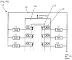
- FIG. 10 shows a condition detection system, generally designated by reference number 120, according to an exemplary embodiment of the present invention.
- the output of the sense circuit 112 for all fluid chambers are connected to a single sense bus 122.
- the cavitation protection layer acts as the first electrode common to all chambers, a voltage step function is applied to a single stimulus node 124 that delivers the step function to the cavitation protection layer.
- the state of all chambers can be read at a single sense bus output 126.
- the sense bus 122 may be configured to be normally digitally high.
- the ink sense circuits 112 may be configured so that the output of any one ink sense circuit 112 may pull the sense bus 122 to the low state. For example, reading a digital low value from the sense bus output 126 would indicate that at least one of the chambers had de-primed or that the cartridge was depleted of ink. Alternatively, reading a digital low value may indicate that ink is still present in at least one of the chambers after printing, which would indicate that at least one of the heaters did not fire.
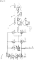
- FIG. 11 is a circuit diagram showing the electrical connection between the sense bus 122 and a plurality of ink sense circuits 112 according to an exemplary embodiment of the present invention.
- the sense bus 122 is used to detect any ink sense failures on a plurality of ink cells.
- the sense bus 122 in this embodiment is a single pulldown wire 122 that connects multiple ink sense cells in a "wired or" connection. If any one of the ink sense circuits 112 has ink detected then its NMOS pulldown transistor will be activated and the sense bus 122 will be "pulled” to a logic low state.
- the systems and methods described could be used to detect the presence or absence of a vapor bubble in the chamber.
- ink is ejected from a chamber by the growth of a vapor bubble at the surface of the heating element.
- the vapor bubble continues to grow into the throat until the pressure from the ink in the via overcomes the force of the vapor bubble and the bubble collapses and ink refills the chamber.
- the first and second electrodes 106, 110 are still in fluid commination when the bubble begins to nucleate.
- the vapor bubble extends to the second electrode 110, thereby breaking the fluidic path. In this state, the cell will read the same as if the chamber was empty. By sensing the cell at the appropriate time after nucleation, it is possible to determine if the bubble properly formed and the system can be used to gauge the overall health of the nozzle.
- the pulldown wire or bus connection may be extended to sensing, depending on the test mode, either the presence of ink or the lack of ink (i.e., a "bubble") on any inkjet heater cell in a group.
- the ink sense circuit described previously may be modified to include an "exclusive or” (xor) logic cell 214 and a new input signal, the "inv_pulldown_sense” (ips) signal 216.
- the ips signal 216 is used with the xor logic cell 214 to invert the logic state required to activate the pulldown NMOS transistor.
- a logic low ips signal will cause the pulldown circuit to activate or set the pulldown wire to a low state when any ink sense cell has ink present.
- a logic high state ips signal will cause the pulldown circuit to activate or set the pulldown wire to a low state when any ink sense cell does not have ink (i.e., detect a bubble).
- the ips signal allows any groups of inkjet heater cells to be checked for ink present (non-firing heater) or ink absent (a bubble) using a single wire and sensing at the correct instant in time.
Description
- This invention is related to inkjet printheads, and in particular to systems and methods for detecting condition of an inkjet printhead nozzle.
- Detecting the health of an inkjet nozzle has been a long standing problem in the field. With scanning printheads the ability to perform multiple passes has been used to minimize the impact of missing or improperly performing nozzles. As inkjet technology pushes into the laser printer performance space, printheads with nozzles spanning the entire page width have become more common. Using this printing method yields improved print speeds but no longer allows for multi-pass printing. Therefore, a method to verify that a nozzle is jetting properly is needed.
- One such method is by optical detection as disclosed in
US Patent Nos. 8,177,318 ,US 8,376,506 andUS 8,449,068 , as well as others. This method requires external light sources and sensors which can add cost and complexity to the printing device. In an effort to eliminate the need for external devices, other methods have been disclosed which place impedance sensors on the ejector chip itself. - One possible implementation of this method is described in
US Patent Nos. 8,870,322 andUS 8,899,709 andUS Patent Application Publication No. 2014/0333694 . These patents and application teach the use of either differential or single ended impedance measurements taken over time to detect the formation and collapse of thermal vapor bubbles. It is further taught that different types of nozzle conditions such as blocked or weak nozzles can be determined by external processing of the data collected from the sensors. As shown inUS Patent No. 8,870,322 , a method of calibration may be required to provide adequate performance of the system. These conventional techniques of detecting printhead condition require analysis of each sensor output at each ink chamber to determine whether the nozzle corresponding to that chamber is firing properly. This does not allow for a practical and efficient detection method. -
US 5 992 984 A describes a printhead comprising a fluid chamber, a heat generating portion disposed in the fluid chamber, a first electrode disposed in the area of the fluid chamber, and a second electrode disposed in the area of the fluid chamber. A detecting pulse is supplied to the second electrode and a response is received at the first electrode. A comparator generates an output representing presence or absence of liquid in the chamber. Further,US 2002/0021315 A1 describes a printhead comprising nozzle portions being in fluid communication with a liquid chamber, a heating element disposed in each nozzle portion, and a detection electrode disposed in the liquid chamber, wherein, when voltage is applied to the heating elements, a response is captured at the detection electrode, the response depending on the presence or absence of ink in the nozzle portions.US 2013/0278656 A1 discloses detecting presence or absence of ink in a fluid chamber by aid of an impedance sensor. - An object of the present invention is to provide a practical method of stimulating an inkjet printhead and sensing the response to determine the condition of the printhead nozzles.
- Another object of the present invention is to provide an fluid sense circuit that can sense the state of multiple nozzles on a single bus line.
- Another object of the present invention is to provide a system that has the ability to stimulate a printhead condition detection cell using a single common input.
- Another object of the present invention is to provide a printhead condition detection system that uses a cavitation protection layer as an electrode in a condition detection cell.
- A fluid printhead according to an example of the present invention comprises: at least one fluid ejection element comprising: a fluid chamber; a throat portion through which fluid is provided to the fluid chamber; and a heater element disposed within the fluid chamber; and a printhead condition detection system comprising: a first electrode at least a portion of which is disposed within the fluid chamber, the first electrode configured to receive a step voltage; a second electrode disposed within the throat portion; and a sense circuit electrically connected to the second electrode that generates an output based on the application of the step voltage to the first electrode as an indication of printhead condition.
- According to the invention, the printhead is as recited in
claim 1. - In an exemplary embodiment, the output of the sense circuit is a digital high output upon a condition that fluid is present in the fluid chamber.
- In an exemplary embodiment, the output of the sense circuit is a digital low output upon a condition that fluid is not present in the fluid chamber.
- Other features and advantages of embodiments of the invention will become readily apparent from the following detailed description, the accompanying drawings and the appended claims.
- The fluid printhead according to the present invention can provide a practical method of stimulating an inkjet printhead and sensing the response to determine the condition of the printhead nozzles.
- The features and advantages of exemplary embodiments of the present invention will be more fully understood with reference to the following, detailed description when taken in conjunction with the accompanying figures, wherein:
-
- [
Fig. 1 ]
FIG. 1 is a perspective view of an inkjet printhead according to an exemplary embodiment of the present invention; - [
Fig. 2 ]
FIG. 2 is a perspective view of an inkjet printer according to an exemplary embodiment of the present invention; - [
Fig. 3 ]
FIG. 3 is a planar view of a printhead condition detection cell according to an exemplary embodiment of the present invention; - [
Fig. 4 ]
FIG. 4 is a planar view of a printhead condition detection cell according to an exemplary embodiment of the present invention in a steady state; - [
Fig. 5 ]
FIG. 5 is a circuit diagram representing the electrochemical interaction between elements of the printhead condition detection cell ofFIG. 4 ; - [
Fig. 6 ]
FIG. 6 shows the measured response to a 5V input for a condition detection cell with ink present according to an exemplary embodiment of the present invention; - [
Fig. 7 ]
FIG. 7 shows the measured response to a 5V input for a condition detection cell with no ink present according to an exemplary embodiment of the present invention; - [
Fig. 8 ]
FIG. 8 shows how the equivalent series resistance and double layer capacitance can be calculated based on the response of a condition detection cell according to an exemplary embodiment of the present invention; - [
Fig. 9 ]
FIG. 9 is a circuit diagram of a sense circuit according to an exemplary embodiment of the present invention; - [
Fig. 10 ]
FIG. 10 is a block diagram of a printhead condition detection system according to an exemplary embodiment of the present invention; - [
Fig. 11 ]
FIG. 11 is a circuit diagram showing electrical connection between ink sense circuits and a sense bus according to an exemplary embodiment of the present invention; - [
Fig. 12 ]
FIG. 12 is a circuit diagram showing electrical connection between an ink sense circuit and a sense bus according to an exemplary embodiment of the present invention; - [
Fig. 13 ]
FIG. 13 is a planar view of a printhead condition detection cell according to an exemplary embodiment of the present invention with a vapor bubble beginning to form; and - [
Fig. 14 ]
FIG. 14 is a planar view of a printhead condition detection cell according to an exemplary embodiment of the present invention with a vapor bubble fully formed. - The headings used herein are for organizational purposes only and are not meant to be used to limit the scope of the description or the claims. As used throughout this application, the words "may" and "can" are used in a permissive sense (i.e., meaning having the potential to), rather than the mandatory sense (i.e., meaning must). Similarly, the words "include," "including," and "includes" mean including but not limited to. To facilitate understanding, like reference numerals have been used, where possible, to designate like elements common to the figures.
- In an electrochemical system an electrode used to probe a system rather than to effect a compositional change is defined as a microelectrode. Further, a microelectrode with a critical dimension less than 25um is termed an ultra-microelectrode or UME. According to exemplary embodiments of the present invention, a global microelectrode as well as individual band UMEs within each ejection element throat are used to sense the presence or absence of ink.
- With reference to
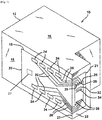
FIG. 1 , an inkjet printhead according to an exemplary embodiment of the present invention is shown generally as 10. Theprinthead 10 has ahousing 12 formed of any suitable material for holding ink. Its shape can vary and often depends upon the external device that carries or contains the printhead. The housing has at least onecompartment 16 internal thereto for holding an initial or refillable supply of ink. In one embodiment, the compartment has a single chamber and holds a supply of black ink, photo ink, cyan ink, magenta ink or yellow ink. In other embodiments, the compartment has multiple chambers and contains three supplies of ink. Preferably, it includes cyan, magenta and yellow ink. In still other embodiments, the compartment contains plurals of black, photo, cyan, magenta or yellow ink. It will be appreciated, however, that while thecompartment 16 is shown as locally integrated within ahousing 12 of the printhead, it may alternatively connect to a remote source of ink and receive supply from a tube, for example. - Adhered to one
surface 18 of thehousing 12 is aportion 19 of a flexible circuit, especially a tape automated bond (TAB)circuit 20. Theother portion 21 of theTAB circuit 20 is adhered to anothersurface 22 of the housing. In this embodiment, the twosurfaces edge 23 of the housing. - The
TAB circuit 20 supports a plurality of input/output (I/O)connectors 24 thereon for electrically connecting aheater chip 25 to an external device, such as a printer, fax machine, copier, photo-printer, plotter, all-in-one, etc., during use. Pluralities ofelectrical conductors 26 exist on theTAB circuit 20 to electrically connect and short the I/O connectors 24 to the input terminals (bond pads 28) of theheater chip 25. Those skilled in the art know various techniques for facilitating such connections. For simplicity,FIG. 1 only shows eight I/O connectors 24, eightelectrical conductors 26 and eightbond pads 28 but present day printheads have much larger quantities and any number is equally embraced herein. Still further, those skilled in the art should appreciate that while such number of connectors, conductors and bond pads equal one another, actual printheads may have unequal numbers. - The
heater chip 25 contains acolumn 34 of a plurality of fluid firing elements that serve to eject ink fromcompartment 16 during use. The fluid firing elements may embody thermally resistive heater elements (heaters for short) formed as thin film layers on a silicon substrate or piezoelectric elements despite the thermal technology implication derived from the name heater chip. For simplicity, the pluralities of fluid firing elements incolumn 34 are shown adjacent an ink via 32 as a row of five dots but in practice may include several hundred or thousand fluid firing elements. As described below, vertically adjacent ones of the fluid firing elements may or may not have a lateral spacing gap or stagger there between. In general, the fluid firing elements have vertical pitch spacing comparable to the dots-per-inch resolution of an attendant printer. Some examples include spacing of 1/300th, 1/600th, 1/1200th, 1/2400th or other of an inch along the longitudinal extent of the via. To form the vias, many processes are known that cut or etch the via 32 through a thickness of the heater chip. Some of the more preferred processes include grit blasting or etching, such as wet, dry, reactive-ion-etching, deep reactive-ion-etching, or other. A nozzle plate (not shown) has orifices thereof aligned with each of the heaters to project the ink during use. The nozzle plate may attach with an adhesive or epoxy or may be fabricated as a thin-film layer. - A
memory unit 27 stores data related to information such as, for example, the production date, the lifetime and the number of refilled times that can be made. - With reference to
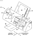
FIG. 2 , an external device in the form of an inkjet printer for containing theprinthead 10 is shown generally as 40. Theprinter 40 includes acarriage 42 having a plurality ofslots 44 for containing one ormore printheads 10. Thecarriage 42 reciprocates (in accordance with anoutput 59 of a controller 57) along ashaft 48 above aprint zone 46 by a motive force supplied to adrive belt 50 as is well known in the art. The reciprocation of thecarriage 42 occurs relative to a print medium, such as a sheet ofpaper 52 that advances in theprinter 40 along a paper path from aninput tray 54, through theprint zone 46, to anoutput tray 56. - While in the print zone, the
carriage 42 reciprocates in the Reciprocating Direction generally perpendicularly to thepaper 52 being advanced in the Advance Direction as shown by the arrows. Ink drops from compartment 16 (FIG. 1 ) are caused to be eject from theheater chip 25 at such times pursuant to commands of a printer microprocessor orother controller 57. The timing of the ink drop emissions corresponds to a pattern of pixels of the image being printed. Often times, such patterns become generated in devices electrically connected to the controller 57 (via Ext. input) that reside externally to the printer and include, but are not limited to, a computer, a scanner, a camera, a visual display unit, a personal data assistant, or other. - To print or emit a single drop of ink, the fluid firing elements (the dots of
column 34,FIG. 1 ) are uniquely addressed with a small amount of current to rapidly heat a small volume of ink. This causes the ink to vaporize in a local ink chamber between the heater and the nozzle plate and eject through, and become projected by, the nozzle plate towards the print medium. The fire pulse required to emit such ink drop may embody a single or a split firing pulse and is received at the heater chip on an input terminal (e.g., bond pad 28) from connections between thebond pad 28, theelectrical conductors 26, the I/O connectors 24 andcontroller 57. Internal heater chip wiring conveys the fire pulse from the input terminal to one or many of the fluid firing elements. - A
control panel 58, havinguser selection interface 60, also accompanies many printers as aninput 62 to thecontroller 57 to provide additional printer capabilities and robustness. -
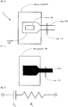
FIG. 3 is a planar view of a fluid ejection element, generally designated byreference number 100, according to an exemplary embodiment of the present invention. Thefluid ejection element 100 includes afluid chamber 102 formed using photolithographic methods to image and develop the feature in a photosensitive material. Thechamber 102 may have a thickness of about 15um. A thinfilm heating element 104 is located within thechamber 102. Theheating element 104 can be energized by applying a voltage potential across the device. In a typical inkjet application, the temperature at the surface of the heating element will increase from ambient to about 350°C in less than 1us. In the case where the chamber is filled with an aqueous ink solution, a vapor bubble will form at the surface of the heating element and then quickly expand. It is this expansion which forces ink out of the chamber through a nozzle orifice. Typically a nozzle (not shown inFIG. 3 ) is located above theheating element 104. The dimensions of theheating element 104 is highly dependent on the drop size and characteristics of the liquid to be ejected, but in general the aspect ratio (Length/Width) of the element is usually between 1 and 3. In an exemplary embodiment, theheating element 104 is formed by depositing a thin layer, about 800A, of TaAIN. - After ink or other fluid is ejected from the
chamber 102 through the nozzle opening the vapor bubble will collapse. The collapse of the bubble exerts a significant cavitation force which would quickly destroy theheating element 104. It is for that reason that a cavitation protection layer is applied about theheating element 104. In an exemplary embodiment, the cavitation protection layer is made of tantalum. While tantalum is typically used because of material hardness and chemical resistance, other materials could be used as well. As explained in more detail below, the cavitation protection layer functions as afirst electrode 106 of a condition detection cell corresponding to thefluid ejection element 100 within a printhead condition detection system. Other fluid ejection elements within the printhead share the same cavitation layer, which also serves asfirst electrodes 106 for each condition detection cell corresponding to those ejection elements. - The
fluid sensor element 100 also includes asecond electrode 110. Thesecond electrode 110 is disposed in thethroat 108 of each fluid ejection element. For the purposes of the present disclosure, the "throat" may be defined as a passage that provides a flow path between the fluid via (not shown) and thefluid chamber 102. Thethroat 108 is formed from the same material and in the same manner as thechamber 102. Thesecond electrode 110 is a band UME and, in an exemplary embodiment, may also be made of Ta and deposited and etched at the same time as the first electrode/cavitation protection layer 106 for process efficiency. It should be understood that thesecond electrode 110 may be formed from other materials that provide improved printhead condition sensor performance. -
FIG. 4 shows thefluid ejection element 100 in a steady state with the element filled with liquid. As shown, thefirst electrode 106 andsecond electrode 110 are now fluidly connected. It is known from electrochemical principles that the relationship between the fluid and the first andsecond electrodes FIG. 5 . It should be understood that in the case where liquid is not present the double layer capacitor does not exist and the series resistance would appear as an open circuit. - With this understanding of the properties of the condition detection cell it is possible to consider practical methods of detecting the presence or absence of liquid between the two electrodes. For inkjet printing or other liquid dispensing applications is it desirable to be able to sense the condition of each chamber on the ejector chip. This design goal must be balanced with the desire to keep die size as small as possible as well as maintaining a simple interface.
- In an exemplary embodiment of the present invention, a voltage step is applied to the system and the resulting response is used to sense the presence or absence of liquid from the system.
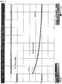
FIG. 6 shows the measured response to a 5V input for a condition detection cell with ink present.FIG. 7 shows the measured response with no ink present. Further,FIG. 8 shows how the equivalent series resistance and double layer capacitance can be calculated based on the response of the cell. While this enables the use of a simple input, a voltage step, a practical method of measurement is still needed. Apreferred sense circuit 112 for making such a measurement is shown inFIG. 9 . - The
sense circuit 112 provides a digital high output when ink is present in the condition detection cell and a digital low output when the cell is empty. There is no need for complicated and space consuming sampling of the cells analog output to determine the state of the cell. This represents a significant on-chip space savings. - The
sense circuit 112 of this exemplary embodiment may be grouped into seven functional blocks. Thebias block 202 develops a current bias used by thethreshold detection block 204. Thesampling block 206 connects the sampling pad to the samplecurrent mirror 208 when the sense pin is at a high state. The samplecurrent mirror 208 then replicates the ink current sensed and the current flows into the thresholdcurrent detection block 204. If the mirrored current sensed is greater than the threshold current then ink is present and theinverter block 210 produces a low state at the input of thelatch block 212 and the latch block detect pin will go to a high state. The latch is required because of the transient charging nature of the current that flows through the ink. If ink is not present then the sampled current will be much less (almost zero) than the threshold detect current. The inverter will then produce a high state which also produces a low state at the latch detect output. The latch is a memory element and its state will persist until its sense_reset pin is forced to a high state. The high state of the sense_reset pin will clear the latch's detect output pin to a low state. In summary, a transient current pulse through the ink causes the latch to trigger and its detect output pin will be latched at a high state or the "ink sensed" state. -
FIG. 10 shows a condition detection system, generally designated byreference number 120, according to an exemplary embodiment of the present invention. To continue the goal of providing a practical method of sensing the state of all nozzles on a chip, the output of thesense circuit 112 for all fluid chambers are connected to asingle sense bus 122. Additionally, since the cavitation protection layer acts as the first electrode common to all chambers, a voltage step function is applied to a single stimulus node 124 that delivers the step function to the cavitation protection layer. The state of all chambers can be read at a singlesense bus output 126. Thesense bus 122 may be configured to be normally digitally high. Thus, theink sense circuits 112 may be configured so that the output of any oneink sense circuit 112 may pull thesense bus 122 to the low state. For example, reading a digital low value from thesense bus output 126 would indicate that at least one of the chambers had de-primed or that the cartridge was depleted of ink. Alternatively, reading a digital low value may indicate that ink is still present in at least one of the chambers after printing, which would indicate that at least one of the heaters did not fire. -
FIG. 11 is a circuit diagram showing the electrical connection between thesense bus 122 and a plurality ofink sense circuits 112 according to an exemplary embodiment of the present invention. In this embodiment, thesense bus 122 is used to detect any ink sense failures on a plurality of ink cells. Thesense bus 122 in this embodiment is a singlepulldown wire 122 that connects multiple ink sense cells in a "wired or" connection. If any one of theink sense circuits 112 has ink detected then its NMOS pulldown transistor will be activated and thesense bus 122 will be "pulled" to a logic low state. This allows a strategy where a group of inkjet heaters may be fired and immediately sensed using the "sense" signal to detect a failure or non-firing heater because the ink is still present. This method allows many heaters to be checked at the same time and requires only one wire to connect any or all heaters in the array. This reduces the time required to detect failures and reduces the area needed for the detection system. - In an exemplary embodiment, the systems and methods described could be used to detect the presence or absence of a vapor bubble in the chamber. As previously discussed and as shown in
FIG. 13 , ink is ejected from a chamber by the growth of a vapor bubble at the surface of the heating element. As shown inFIG. 14 , after the ink is ejected from the chamber, the vapor bubble continues to grow into the throat until the pressure from the ink in the via overcomes the force of the vapor bubble and the bubble collapses and ink refills the chamber. As shown inFIG. 13 , the first andsecond electrodes second electrode 110, thereby breaking the fluidic path. In this state, the cell will read the same as if the chamber was empty. By sensing the cell at the appropriate time after nucleation, it is possible to determine if the bubble properly formed and the system can be used to gauge the overall health of the nozzle. - The pulldown wire or bus connection may be extended to sensing, depending on the test mode, either the presence of ink or the lack of ink (i.e., a "bubble") on any inkjet heater cell in a group. In this regard, as shown in
FIG. 12 , the ink sense circuit described previously may be modified to include an "exclusive or" (xor)logic cell 214 and a new input signal, the "inv_pulldown_sense" (ips)signal 216. The ips signal 216 is used with thexor logic cell 214 to invert the logic state required to activate the pulldown NMOS transistor. A logic low ips signal will cause the pulldown circuit to activate or set the pulldown wire to a low state when any ink sense cell has ink present. A logic high state ips signal will cause the pulldown circuit to activate or set the pulldown wire to a low state when any ink sense cell does not have ink (i.e., detect a bubble). Thus, the ips signal allows any groups of inkjet heater cells to be checked for ink present (non-firing heater) or ink absent (a bubble) using a single wire and sensing at the correct instant in time. - While particular embodiments of the invention have been illustrated and described, it would be obvious to those skilled in the art that various other changes and modifications may be made without departing from the scope of the invention. It is therefore intended to cover in the appended claims all such changes and modifications that are within the scope of this invention.
-
- 10:
- printhead
- 12:
- housing
- 16:
- compartment
- 18,22:
- surface
- 19,21:
- portion
- 20:
- TAB circuit
- 23:
- edge
- 24:
- I/O connector
- 25:
- heater chip
- 26:
- electrical conductor
- 28:
- bond pad
- 32:
- ink via
- 34:
- column
- 40:
- printer
- 42:
- carriage
- 44:
- slot
- 46:
- print zone
- 48:
- shaft
- 50:
- drive belt
- 52:
- paper
- 54:
- input tray
- 56:
- output tray
- 57:
- controller
- 58:
- control panel
- 59:
- output
- 60:
- user selection interface
- 62:
- input
- 100:
- fluid ejection element
- 102:
- fluid chamber
- 104:
- heating element
- 106:
- first electrode
- 108:
- throat
- 110:
- second electrode
- 112:
- sense circuit
- 120:
- condition detection system
- 122:
- single sense bus
- 126:
- single sense bus output
- 202:
- bias block
- 204:
- threshold detection block
- 206:
- sampling block
- 208:
- sample current mirror
- 210:
- inverter block
- 212:
- latch block
- 214:
- xor logic cell
- 216:
- ips signal
Claims (4)
- A fluid printhead (10), comprising:a plurality of fluid ejection elements (100) each comprising:a fluid chamber (102);a throat portion (108) through which fluid is provided to the fluid chamber (102); anda heater element (104) disposed within the fluid chamber (102); anda printhead condition detection system (120) comprising:
a stimulus node (124) configured to deliver a step voltage;a first electrode (106) at least a portion of which is disposed within the plurality of fluid chambers (102), and which is electrically connected to the stimulus node (124), the first electrode (106) configured to receive the step voltage delivered from the stimulus node (124) and being shared by the plurality of fluid chambers (102);
a plurality of second electrodes (110) each disposed within one of the throat portions (108) of the plurality of fluid ejection elements (100);
a plurality of sense circuits (112) each electrically connected to one of the plurality of second electrodes (110), the plurality of sense circuits (112) being configured to generate an output based on a response resulting from the application of the step voltage to the first electrode (106) as an indication of printhead condition; and
a sense bus configured to receive the output from the plurality of sense circuits (112). - The fluid printhead (10) of claim 1, wherein the output of the sense circuit is a digital high output upon a condition that fluid is present in the fluid chamber (102).
- The fluid printhead (10) of claim 1, wherein the output of the sense circuit is a digital low output upon a condition that fluid is not present in the fluid chamber (102).
- A fluid printer system comprising:a housing; andone or more printhead assemblies movably connected to the housing so that the one or more printhead assemblies eject fluid onto a print medium as the one or more printheads move relative to the housing in accordance with a control mechanism, wherein at least one of the one or more printhead assemblies comprises a fluid printhead (10) according to any one of claims 1 to 3.
Priority Applications (2)
| Application Number | Priority Date | Filing Date | Title |
|---|---|---|---|
| EP23169156.9A EP4227104A1 (en) | 2015-04-10 | 2016-03-30 | Fluid printhead and fluid printer system |
| EP21158352.1A EP3842237B1 (en) | 2015-04-10 | 2016-03-30 | Fluid printhead and fluid printer system |
Applications Claiming Priority (2)
| Application Number | Priority Date | Filing Date | Title |
|---|---|---|---|
| US14/683,699 US9493002B2 (en) | 2015-04-10 | 2015-04-10 | Printhead condition detection system |
| PCT/JP2016/001847 WO2016163105A1 (en) | 2015-04-10 | 2016-03-30 | Fluid printhead and fluid printer system |
Related Child Applications (3)
| Application Number | Title | Priority Date | Filing Date |
|---|---|---|---|
| EP23169156.9A Division EP4227104A1 (en) | 2015-04-10 | 2016-03-30 | Fluid printhead and fluid printer system |
| EP21158352.1A Division EP3842237B1 (en) | 2015-04-10 | 2016-03-30 | Fluid printhead and fluid printer system |
| EP21158352.1A Division-Into EP3842237B1 (en) | 2015-04-10 | 2016-03-30 | Fluid printhead and fluid printer system |
Publications (3)
| Publication Number | Publication Date |
|---|---|
| EP3280595A1 EP3280595A1 (en) | 2018-02-14 |
| EP3280595A4 EP3280595A4 (en) | 2018-11-21 |
| EP3280595B1 true EP3280595B1 (en) | 2021-05-12 |
Family
ID=57071815
Family Applications (3)
| Application Number | Title | Priority Date | Filing Date |
|---|---|---|---|
| EP21158352.1A Active EP3842237B1 (en) | 2015-04-10 | 2016-03-30 | Fluid printhead and fluid printer system |
| EP23169156.9A Pending EP4227104A1 (en) | 2015-04-10 | 2016-03-30 | Fluid printhead and fluid printer system |
| EP16776278.0A Active EP3280595B1 (en) | 2015-04-10 | 2016-03-30 | Fluid printhead and fluid printer system |
Family Applications Before (2)
| Application Number | Title | Priority Date | Filing Date |
|---|---|---|---|
| EP21158352.1A Active EP3842237B1 (en) | 2015-04-10 | 2016-03-30 | Fluid printhead and fluid printer system |
| EP23169156.9A Pending EP4227104A1 (en) | 2015-04-10 | 2016-03-30 | Fluid printhead and fluid printer system |
Country Status (5)
| Country | Link |
|---|---|
| US (3) | US9493002B2 (en) |
| EP (3) | EP3842237B1 (en) |
| JP (3) | JP6741015B2 (en) |
| CN (2) | CN107428167B (en) |
| WO (1) | WO2016163105A1 (en) |
Families Citing this family (29)
| Publication number | Priority date | Publication date | Assignee | Title |
|---|---|---|---|---|
| US9493002B2 (en) * | 2015-04-10 | 2016-11-15 | Funai Electric Co., Ltd. | Printhead condition detection system |
| CN109641455B (en) * | 2016-10-31 | 2020-08-04 | 惠普发展公司,有限责任合伙企业 | Fluid ejection device combining drive bubble detection and thermal response |
| WO2018186852A1 (en) | 2017-04-05 | 2018-10-11 | Hewlett-Packard Development Company, L.P. | On-die actuator failure detection |
| US10786987B2 (en) | 2017-04-05 | 2020-09-29 | Hewlett-Packard Development Company, L.P. | On-die time-shifted actuator evaluation |
| CN110325369B (en) | 2017-04-05 | 2021-09-24 | 惠普发展公司,有限责任合伙企业 | On-die actuator disabling |
| US10850509B2 (en) | 2017-04-05 | 2020-12-01 | Hewlett-Packard Development Company, L.P. | On-die actuator evaluation with pre-charged thresholds |
| US10882310B2 (en) | 2017-04-05 | 2021-01-05 | Hewlett-Packard Development Company, L.P. | On-die actuator evaluation |
| US10875298B2 (en) | 2017-04-14 | 2020-12-29 | Hewlett-Packard Development Company, L.P. | Delay elements for activation signals |
| CN110446612B (en) * | 2017-04-24 | 2020-10-16 | 惠普发展公司,有限责任合伙企业 | Fluid ejection die including strain gauge sensor |
| WO2019017951A1 (en) * | 2017-07-20 | 2019-01-24 | Hewlett-Packard Development Company, L.P. | Fluidic die sense architecture |
| WO2019143328A1 (en) * | 2018-01-17 | 2019-07-25 | Hewlett-Packard Development Company, L.P. | Storing measurements of nozzle conditions |
| US11524498B2 (en) | 2018-04-06 | 2022-12-13 | Hewlett-Packard Development Company, L.P. | Decoders to activate fluidic actuators for sense measurements |
| US11312131B2 (en) | 2018-04-06 | 2022-04-26 | Hewlett-Packard Development Company, L.P. | Sense measurement indicators to select fluidic actuators for sense measurements |
| US11186080B2 (en) | 2018-04-06 | 2021-11-30 | Hewlett-Packard Development Company, L.P. | Reference measurements of fluidic actuators |
| US11173712B2 (en) | 2018-04-06 | 2021-11-16 | Hewlett-Packard Development Company, L.P. | Sense measurements for fluidic actuators |
| WO2019194831A1 (en) | 2018-04-06 | 2019-10-10 | Hewlett-Packard Development Company, L.P. | Fluidic actuator activations for sense measurements |
| US20210053344A1 (en) * | 2018-05-15 | 2021-02-25 | Hewlett-Packard Development Company, L.P. | Fluidic die with monitoring circuit using floating power node |
| CN109501437B (en) * | 2018-10-16 | 2020-01-10 | 中国科学院化学研究所 | Screen gauze for screen printing plate and preparation method thereof |
| WO2020106289A1 (en) | 2018-11-21 | 2020-05-28 | Hewlett-Packard Development Company, L.P. | Fluidic dies with selectors adjacent respective firing subassemblies |
| US11559987B2 (en) | 2019-01-31 | 2023-01-24 | Hewlett-Packard Development Company, L.P. | Fluidic die with surface condition monitoring |
| US11787173B2 (en) | 2019-02-06 | 2023-10-17 | Hewlett-Packard Development Company, L.P. | Print component with memory circuit |
| CN115848018A (en) | 2019-02-06 | 2023-03-28 | 惠普发展公司,有限责任合伙企业 | Integrated circuit for fluid ejection apparatus and fluid ejection apparatus |
| AU2019428297B2 (en) | 2019-02-06 | 2023-03-09 | Hewlett-Packard Development Company, L.P. | Multiple circuits coupled to an interface |
| KR102621218B1 (en) | 2019-02-06 | 2024-01-04 | 휴렛-팩커드 디벨롭먼트 컴퍼니, 엘.피. | Memory in fluid die |
| MX2021009125A (en) | 2019-02-06 | 2021-09-21 | Hewlett Packard Development Co | Print component with memory circuit. |
| SG11202107300YA (en) | 2019-02-06 | 2021-08-30 | Hewlett Packard Development Co Lp | Communicating print component |
| US11896971B2 (en) | 2021-03-18 | 2024-02-13 | Punai Electric Co., Ltd. | Fluid detection circuit for fluid ejection head |
| US20220297424A1 (en) * | 2021-03-18 | 2022-09-22 | Funai Electric Co., Ltd. | Pipette-fillable cartridge fluid detection |
| US11686696B2 (en) * | 2021-09-13 | 2023-06-27 | Funai Electric Co., Ltd. | Fluid sense circuit with variable sensitivity |
Family Cites Families (31)
| Publication number | Priority date | Publication date | Assignee | Title |
|---|---|---|---|---|
| US4853718A (en) * | 1988-08-15 | 1989-08-01 | Xerox Corporation | On chip conductive fluid sensing circuit |
| US5105085A (en) * | 1989-11-17 | 1992-04-14 | Mcguire Danny G | Fluid analysis system |
| JPH07178924A (en) | 1993-12-22 | 1995-07-18 | Canon Inc | Ink jet recording apparatus and method therefor |
| ATE194553T1 (en) | 1993-12-28 | 2000-07-15 | Canon Kk | SUBSTRATE FOR AN INKJET HEAD, INKJET HEAD AND INKJET DEVICE |
| JP3184737B2 (en) * | 1994-05-27 | 2001-07-09 | キヤノン株式会社 | Recording head, recording head unit, ink tank, and ink jet recording apparatus having the recording head |
| US5721574A (en) * | 1995-12-11 | 1998-02-24 | Xerox Corporation | Ink detecting mechanism for a liquid ink printer |
| EP0819531B1 (en) * | 1996-07-09 | 2003-09-24 | Canon Kabushiki Kaisha | Liquid discharging head, head cartridge and liquid discharge apparatus |
| US6122689A (en) * | 1998-05-13 | 2000-09-19 | Adaptec, Inc. | Bus termination circuitry and methods for implementing the same |
| JP2001063097A (en) * | 1999-04-27 | 2001-03-13 | Canon Inc | Liquid feed system and liquid feed container used in the system |
| US6652053B2 (en) | 2000-02-18 | 2003-11-25 | Canon Kabushiki Kaisha | Substrate for ink-jet printing head, ink-jet printing head, ink-jet cartridge, ink-jet printing apparatus, and method for detecting ink in ink-jet printing head |
| JP2001322298A (en) * | 2000-05-16 | 2001-11-20 | Canon Inc | Ink jet recorder, and method for detecting state of ink in ink jet head |
| JP2001322277A (en) * | 2000-05-16 | 2001-11-20 | Canon Inc | Ink jet recorder |
| JP2002127404A (en) | 2000-10-19 | 2002-05-08 | Canon Inc | Ink jet recording head and ink jet recorder |
| JP3697209B2 (en) * | 2001-12-27 | 2005-09-21 | キヤノン株式会社 | Liquid discharge detection method and apparatus and ink jet recording apparatus |
| JP2004009491A (en) * | 2002-06-06 | 2004-01-15 | Canon Inc | Ink state sensing mechanism |
| JP3849867B2 (en) | 2002-07-24 | 2006-11-22 | ソニー株式会社 | Liquid detection device and liquid amount detection device |
| JP4537659B2 (en) * | 2003-02-14 | 2010-09-01 | エスアイアイ・プリンテック株式会社 | Ink jet head and ink jet recording apparatus |
| JP2008168565A (en) * | 2007-01-15 | 2008-07-24 | Seiko Epson Corp | Fluid jetting device |
| KR20090001219A (en) * | 2007-06-29 | 2009-01-08 | 삼성전자주식회사 | Method for detecting missing nozzle and inkjet print head using it |
| JP5042087B2 (en) | 2008-03-18 | 2012-10-03 | 富士フイルム株式会社 | Control apparatus and control method for droplet discharge head |
| US8177318B2 (en) | 2008-03-25 | 2012-05-15 | Hewlett-Packard Development Company, L.P. | Orifice health detection device |
| US8449068B2 (en) | 2009-02-19 | 2013-05-28 | Hewlett-Packard Development Company, L.P. | Light-scattering drop detector |
| US8376506B2 (en) | 2008-03-25 | 2013-02-19 | Hewlett-Packard Development Company, L.P. | Drop detection |
| JP2010000755A (en) * | 2008-06-23 | 2010-01-07 | Ricoh Co Ltd | Liquid ejection head, method for detecting defective nozzle of liquid ejection head, and image forming apparatus |
| US9517630B2 (en) * | 2011-10-24 | 2016-12-13 | Hewlett-Packard Development Company, L.P. | Inkjet printing system, fluid ejection system, and method thereof |
| US8899709B2 (en) | 2012-04-19 | 2014-12-02 | Hewlett-Packard Development Company, L.P. | Determining an issue with an inkjet nozzle using an impedance difference |
| CN104080610B (en) | 2012-04-19 | 2017-04-19 | 惠普发展公司,有限责任合伙企业 | Detecting a drive bubble formation and collapse |
| US8870322B2 (en) | 2012-04-19 | 2014-10-28 | Hewlett-Packard Development Company, L.P. | Calibrating a program that detects a condition of an inkjet nozzle |
| JP6270358B2 (en) * | 2013-07-09 | 2018-01-31 | キヤノン株式会社 | Liquid discharge head |
| CN203888373U (en) * | 2014-01-08 | 2014-10-22 | 北京兴通盛达科技有限公司 | Novel ink-jet printhead used for ink-jet printer |
| US9493002B2 (en) * | 2015-04-10 | 2016-11-15 | Funai Electric Co., Ltd. | Printhead condition detection system |
-
2015
- 2015-04-10 US US14/683,699 patent/US9493002B2/en active Active
-
2016
- 2016-03-30 EP EP21158352.1A patent/EP3842237B1/en active Active
- 2016-03-30 EP EP23169156.9A patent/EP4227104A1/en active Pending
- 2016-03-30 CN CN201680016989.2A patent/CN107428167B/en active Active
- 2016-03-30 CN CN201910384237.7A patent/CN110126465B/en active Active
- 2016-03-30 JP JP2017547180A patent/JP6741015B2/en active Active
- 2016-03-30 EP EP16776278.0A patent/EP3280595B1/en active Active
- 2016-03-30 WO PCT/JP2016/001847 patent/WO2016163105A1/en active Application Filing
- 2016-10-13 US US15/292,735 patent/US10099477B2/en active Active
-
2018
- 2018-08-13 US US16/101,582 patent/US10717279B2/en active Active
-
2020
- 2020-07-22 JP JP2020124977A patent/JP6947257B2/en active Active
-
2021
- 2021-09-03 JP JP2021143735A patent/JP7173247B2/en active Active
Non-Patent Citations (1)
| Title |
|---|
| None * |
Also Published As
| Publication number | Publication date |
|---|---|
| US20180345667A1 (en) | 2018-12-06 |
| JP6947257B2 (en) | 2021-10-13 |
| WO2016163105A1 (en) | 2016-10-13 |
| EP3842237B1 (en) | 2023-08-23 |
| JP7173247B2 (en) | 2022-11-16 |
| EP4227104A1 (en) | 2023-08-16 |
| CN110126465A (en) | 2019-08-16 |
| US20160297198A1 (en) | 2016-10-13 |
| JP2018510793A (en) | 2018-04-19 |
| CN110126465B (en) | 2020-09-25 |
| JP2020172113A (en) | 2020-10-22 |
| EP3280595A4 (en) | 2018-11-21 |
| JP2021183426A (en) | 2021-12-02 |
| US9493002B2 (en) | 2016-11-15 |
| CN107428167A (en) | 2017-12-01 |
| US10099477B2 (en) | 2018-10-16 |
| EP3842237A1 (en) | 2021-06-30 |
| US10717279B2 (en) | 2020-07-21 |
| JP6741015B2 (en) | 2020-08-19 |
| US20170028724A1 (en) | 2017-02-02 |
| CN107428167B (en) | 2019-06-04 |
| EP3280595A1 (en) | 2018-02-14 |
Similar Documents
| Publication | Publication Date | Title |
|---|---|---|
| US10717279B2 (en) | Printhead condition detection system | |
| US8336981B2 (en) | Determining a healthy fluid ejection nozzle | |
| TWI596016B (en) | Managing printhead nozzle conditions | |
| US8287082B2 (en) | Method of detecting discharging state of inkjet recording head | |
| US9815278B2 (en) | Fluid printhead | |
| US6471318B2 (en) | Ink jet recording head, driving condition setting method thereof, and ink jet recording device | |
| RU2645620C2 (en) | Print head with a plurality of slotted fluid holes | |
| US6513901B1 (en) | Method and apparatus for determining drop volume from a drop ejection device | |
| JP2010064444A (en) | Inkjet recording device and method for controlling the same | |
| JP2017531580A (en) | Print cartridge and inkjet printer | |
| JP2752676B2 (en) | Liquid jet recording apparatus and liquid jet recording head mounted thereon | |
| JP2009101573A (en) | Inkjet recording head |
Legal Events
| Date | Code | Title | Description |
|---|---|---|---|
| STAA | Information on the status of an ep patent application or granted ep patent |
Free format text: STATUS: THE INTERNATIONAL PUBLICATION HAS BEEN MADE |
|
| PUAI | Public reference made under article 153(3) epc to a published international application that has entered the european phase |
Free format text: ORIGINAL CODE: 0009012 |
|
| STAA | Information on the status of an ep patent application or granted ep patent |
Free format text: STATUS: REQUEST FOR EXAMINATION WAS MADE |
|
| 17P | Request for examination filed |
Effective date: 20170928 |
|
| AK | Designated contracting states |
Kind code of ref document: A1 Designated state(s): AL AT BE BG CH CY CZ DE DK EE ES FI FR GB GR HR HU IE IS IT LI LT LU LV MC MK MT NL NO PL PT RO RS SE SI SK SM TR |
|
| AX | Request for extension of the european patent |
Extension state: BA ME |
|
| DAV | Request for validation of the european patent (deleted) | ||
| DAX | Request for extension of the european patent (deleted) | ||
| A4 | Supplementary search report drawn up and despatched |
Effective date: 20181024 |
|
| RIC1 | Information provided on ipc code assigned before grant |
Ipc: B41J 2/14 20060101AFI20181018BHEP Ipc: B41J 2/045 20060101ALI20181018BHEP |
|
| STAA | Information on the status of an ep patent application or granted ep patent |
Free format text: STATUS: EXAMINATION IS IN PROGRESS |
|
| 17Q | First examination report despatched |
Effective date: 20200513 |
|
| GRAP | Despatch of communication of intention to grant a patent |
Free format text: ORIGINAL CODE: EPIDOSNIGR1 |
|
| STAA | Information on the status of an ep patent application or granted ep patent |
Free format text: STATUS: GRANT OF PATENT IS INTENDED |
|
| INTG | Intention to grant announced |
Effective date: 20201214 |
|
| GRAS | Grant fee paid |
Free format text: ORIGINAL CODE: EPIDOSNIGR3 |
|
| GRAA | (expected) grant |
Free format text: ORIGINAL CODE: 0009210 |
|
| STAA | Information on the status of an ep patent application or granted ep patent |
Free format text: STATUS: THE PATENT HAS BEEN GRANTED |
|
| RAP3 | Party data changed (applicant data changed or rights of an application transferred) |
Owner name: FUNAI ELECTRIC CO., LTD. |
|
| AK | Designated contracting states |
Kind code of ref document: B1 Designated state(s): AL AT BE BG CH CY CZ DE DK EE ES FI FR GB GR HR HU IE IS IT LI LT LU LV MC MK MT NL NO PL PT RO RS SE SI SK SM TR |
|
| REG | Reference to a national code |
Ref country code: GB Ref legal event code: FG4D |
|
| REG | Reference to a national code |
Ref country code: CH Ref legal event code: EP |
|
| REG | Reference to a national code |
Ref country code: DE Ref legal event code: R096 Ref document number: 602016057791 Country of ref document: DE |
|
| REG | Reference to a national code |
Ref country code: IE Ref legal event code: FG4D |
|
| REG | Reference to a national code |
Ref country code: AT Ref legal event code: REF Ref document number: 1391929 Country of ref document: AT Kind code of ref document: T Effective date: 20210615 |
|
| REG | Reference to a national code |
Ref country code: LT Ref legal event code: MG9D |
|
| REG | Reference to a national code |
Ref country code: AT Ref legal event code: MK05 Ref document number: 1391929 Country of ref document: AT Kind code of ref document: T Effective date: 20210512 |
|
| REG | Reference to a national code |
Ref country code: NL Ref legal event code: MP Effective date: 20210512 |
|
| PG25 | Lapsed in a contracting state [announced via postgrant information from national office to epo] |
Ref country code: HR Free format text: LAPSE BECAUSE OF FAILURE TO SUBMIT A TRANSLATION OF THE DESCRIPTION OR TO PAY THE FEE WITHIN THE PRESCRIBED TIME-LIMIT Effective date: 20210512 Ref country code: BG Free format text: LAPSE BECAUSE OF FAILURE TO SUBMIT A TRANSLATION OF THE DESCRIPTION OR TO PAY THE FEE WITHIN THE PRESCRIBED TIME-LIMIT Effective date: 20210812 Ref country code: AT Free format text: LAPSE BECAUSE OF FAILURE TO SUBMIT A TRANSLATION OF THE DESCRIPTION OR TO PAY THE FEE WITHIN THE PRESCRIBED TIME-LIMIT Effective date: 20210512 Ref country code: LT Free format text: LAPSE BECAUSE OF FAILURE TO SUBMIT A TRANSLATION OF THE DESCRIPTION OR TO PAY THE FEE WITHIN THE PRESCRIBED TIME-LIMIT Effective date: 20210512 Ref country code: FI Free format text: LAPSE BECAUSE OF FAILURE TO SUBMIT A TRANSLATION OF THE DESCRIPTION OR TO PAY THE FEE WITHIN THE PRESCRIBED TIME-LIMIT Effective date: 20210512 |
|
| PG25 | Lapsed in a contracting state [announced via postgrant information from national office to epo] |
Ref country code: GR Free format text: LAPSE BECAUSE OF FAILURE TO SUBMIT A TRANSLATION OF THE DESCRIPTION OR TO PAY THE FEE WITHIN THE PRESCRIBED TIME-LIMIT Effective date: 20210813 Ref country code: IS Free format text: LAPSE BECAUSE OF FAILURE TO SUBMIT A TRANSLATION OF THE DESCRIPTION OR TO PAY THE FEE WITHIN THE PRESCRIBED TIME-LIMIT Effective date: 20210912 Ref country code: LV Free format text: LAPSE BECAUSE OF FAILURE TO SUBMIT A TRANSLATION OF THE DESCRIPTION OR TO PAY THE FEE WITHIN THE PRESCRIBED TIME-LIMIT Effective date: 20210512 Ref country code: NO Free format text: LAPSE BECAUSE OF FAILURE TO SUBMIT A TRANSLATION OF THE DESCRIPTION OR TO PAY THE FEE WITHIN THE PRESCRIBED TIME-LIMIT Effective date: 20210812 Ref country code: PL Free format text: LAPSE BECAUSE OF FAILURE TO SUBMIT A TRANSLATION OF THE DESCRIPTION OR TO PAY THE FEE WITHIN THE PRESCRIBED TIME-LIMIT Effective date: 20210512 Ref country code: PT Free format text: LAPSE BECAUSE OF FAILURE TO SUBMIT A TRANSLATION OF THE DESCRIPTION OR TO PAY THE FEE WITHIN THE PRESCRIBED TIME-LIMIT Effective date: 20210913 Ref country code: RS Free format text: LAPSE BECAUSE OF FAILURE TO SUBMIT A TRANSLATION OF THE DESCRIPTION OR TO PAY THE FEE WITHIN THE PRESCRIBED TIME-LIMIT Effective date: 20210512 Ref country code: SE Free format text: LAPSE BECAUSE OF FAILURE TO SUBMIT A TRANSLATION OF THE DESCRIPTION OR TO PAY THE FEE WITHIN THE PRESCRIBED TIME-LIMIT Effective date: 20210512 |
|
| PG25 | Lapsed in a contracting state [announced via postgrant information from national office to epo] |
Ref country code: NL Free format text: LAPSE BECAUSE OF FAILURE TO SUBMIT A TRANSLATION OF THE DESCRIPTION OR TO PAY THE FEE WITHIN THE PRESCRIBED TIME-LIMIT Effective date: 20210512 |
|
| PG25 | Lapsed in a contracting state [announced via postgrant information from national office to epo] |
Ref country code: ES Free format text: LAPSE BECAUSE OF FAILURE TO SUBMIT A TRANSLATION OF THE DESCRIPTION OR TO PAY THE FEE WITHIN THE PRESCRIBED TIME-LIMIT Effective date: 20210512 Ref country code: RO Free format text: LAPSE BECAUSE OF FAILURE TO SUBMIT A TRANSLATION OF THE DESCRIPTION OR TO PAY THE FEE WITHIN THE PRESCRIBED TIME-LIMIT Effective date: 20210512 Ref country code: CZ Free format text: LAPSE BECAUSE OF FAILURE TO SUBMIT A TRANSLATION OF THE DESCRIPTION OR TO PAY THE FEE WITHIN THE PRESCRIBED TIME-LIMIT Effective date: 20210512 Ref country code: DK Free format text: LAPSE BECAUSE OF FAILURE TO SUBMIT A TRANSLATION OF THE DESCRIPTION OR TO PAY THE FEE WITHIN THE PRESCRIBED TIME-LIMIT Effective date: 20210512 Ref country code: EE Free format text: LAPSE BECAUSE OF FAILURE TO SUBMIT A TRANSLATION OF THE DESCRIPTION OR TO PAY THE FEE WITHIN THE PRESCRIBED TIME-LIMIT Effective date: 20210512 Ref country code: SM Free format text: LAPSE BECAUSE OF FAILURE TO SUBMIT A TRANSLATION OF THE DESCRIPTION OR TO PAY THE FEE WITHIN THE PRESCRIBED TIME-LIMIT Effective date: 20210512 Ref country code: SK Free format text: LAPSE BECAUSE OF FAILURE TO SUBMIT A TRANSLATION OF THE DESCRIPTION OR TO PAY THE FEE WITHIN THE PRESCRIBED TIME-LIMIT Effective date: 20210512 |
|
| REG | Reference to a national code |
Ref country code: DE Ref legal event code: R097 Ref document number: 602016057791 Country of ref document: DE |
|
| PLBE | No opposition filed within time limit |
Free format text: ORIGINAL CODE: 0009261 |
|
| STAA | Information on the status of an ep patent application or granted ep patent |
Free format text: STATUS: NO OPPOSITION FILED WITHIN TIME LIMIT |
|
| 26N | No opposition filed |
Effective date: 20220215 |
|
| PG25 | Lapsed in a contracting state [announced via postgrant information from national office to epo] |
Ref country code: IS Free format text: LAPSE BECAUSE OF FAILURE TO SUBMIT A TRANSLATION OF THE DESCRIPTION OR TO PAY THE FEE WITHIN THE PRESCRIBED TIME-LIMIT Effective date: 20210912 Ref country code: AL Free format text: LAPSE BECAUSE OF FAILURE TO SUBMIT A TRANSLATION OF THE DESCRIPTION OR TO PAY THE FEE WITHIN THE PRESCRIBED TIME-LIMIT Effective date: 20210512 |
|
| PG25 | Lapsed in a contracting state [announced via postgrant information from national office to epo] |
Ref country code: IT Free format text: LAPSE BECAUSE OF FAILURE TO SUBMIT A TRANSLATION OF THE DESCRIPTION OR TO PAY THE FEE WITHIN THE PRESCRIBED TIME-LIMIT Effective date: 20210512 |
|
| PG25 | Lapsed in a contracting state [announced via postgrant information from national office to epo] |
Ref country code: MC Free format text: LAPSE BECAUSE OF FAILURE TO SUBMIT A TRANSLATION OF THE DESCRIPTION OR TO PAY THE FEE WITHIN THE PRESCRIBED TIME-LIMIT Effective date: 20210512 |
|
| REG | Reference to a national code |
Ref country code: CH Ref legal event code: PL |
|
| GBPC | Gb: european patent ceased through non-payment of renewal fee |
Effective date: 20220330 |
|
| REG | Reference to a national code |
Ref country code: BE Ref legal event code: MM Effective date: 20220331 |
|
| PG25 | Lapsed in a contracting state [announced via postgrant information from national office to epo] |
Ref country code: LU Free format text: LAPSE BECAUSE OF NON-PAYMENT OF DUE FEES Effective date: 20220330 Ref country code: LI Free format text: LAPSE BECAUSE OF NON-PAYMENT OF DUE FEES Effective date: 20220331 Ref country code: IE Free format text: LAPSE BECAUSE OF NON-PAYMENT OF DUE FEES Effective date: 20220330 Ref country code: GB Free format text: LAPSE BECAUSE OF NON-PAYMENT OF DUE FEES Effective date: 20220330 Ref country code: FR Free format text: LAPSE BECAUSE OF NON-PAYMENT OF DUE FEES Effective date: 20220331 Ref country code: CH Free format text: LAPSE BECAUSE OF NON-PAYMENT OF DUE FEES Effective date: 20220331 |
|
| PG25 | Lapsed in a contracting state [announced via postgrant information from national office to epo] |
Ref country code: BE Free format text: LAPSE BECAUSE OF NON-PAYMENT OF DUE FEES Effective date: 20220331 |
|
| PGFP | Annual fee paid to national office [announced via postgrant information from national office to epo] |
Ref country code: DE Payment date: 20230131 Year of fee payment: 8 |
|
| PG25 | Lapsed in a contracting state [announced via postgrant information from national office to epo] |
Ref country code: HU Free format text: LAPSE BECAUSE OF FAILURE TO SUBMIT A TRANSLATION OF THE DESCRIPTION OR TO PAY THE FEE WITHIN THE PRESCRIBED TIME-LIMIT; INVALID AB INITIO Effective date: 20160330 |