EP3280509B1 - Degassing, de-bubbling, and dampening device - Google Patents
Degassing, de-bubbling, and dampening device Download PDFInfo
- Publication number
- EP3280509B1 EP3280509B1 EP16777036.1A EP16777036A EP3280509B1 EP 3280509 B1 EP3280509 B1 EP 3280509B1 EP 16777036 A EP16777036 A EP 16777036A EP 3280509 B1 EP3280509 B1 EP 3280509B1
- Authority
- EP
- European Patent Office
- Prior art keywords
- membrane
- dampening
- chamber
- fluid
- degassing
- Prior art date
- Legal status (The legal status is an assumption and is not a legal conclusion. Google has not performed a legal analysis and makes no representation as to the accuracy of the status listed.)
- Active
Links
- 238000007872 degassing Methods 0.000 title claims description 71
- 239000012530 fluid Substances 0.000 claims description 112
- 239000012528 membrane Substances 0.000 claims description 100
- 239000000463 material Substances 0.000 claims description 18
- -1 polytetrafluoroethylene Polymers 0.000 claims description 12
- 239000011148 porous material Substances 0.000 claims description 9
- 229920001343 polytetrafluoroethylene Polymers 0.000 claims description 8
- 239000004810 polytetrafluoroethylene Substances 0.000 claims description 8
- 239000004809 Teflon Substances 0.000 claims description 6
- 229920006362 Teflon® Polymers 0.000 claims description 6
- 229920001971 elastomer Polymers 0.000 claims description 6
- BFKJFAAPBSQJPD-UHFFFAOYSA-N tetrafluoroethene Chemical compound FC(F)=C(F)F BFKJFAAPBSQJPD-UHFFFAOYSA-N 0.000 claims description 6
- 229920000642 polymer Polymers 0.000 claims description 5
- 229920002379 silicone rubber Polymers 0.000 claims description 5
- 239000004945 silicone rubber Substances 0.000 claims description 5
- 229920002943 EPDM rubber Polymers 0.000 claims description 4
- 230000004044 response Effects 0.000 claims description 4
- 229920006169 Perfluoroelastomer Polymers 0.000 claims description 3
- 239000004743 Polypropylene Substances 0.000 claims description 3
- 239000000560 biocompatible material Substances 0.000 claims description 3
- 239000000919 ceramic Substances 0.000 claims description 3
- 238000004891 communication Methods 0.000 claims description 3
- 239000000806 elastomer Substances 0.000 claims description 3
- 229920002313 fluoropolymer Polymers 0.000 claims description 3
- 239000004811 fluoropolymer Substances 0.000 claims description 3
- 239000002184 metal Substances 0.000 claims description 3
- 229910052751 metal Inorganic materials 0.000 claims description 3
- 229920001155 polypropylene Polymers 0.000 claims description 3
- 239000005060 rubber Substances 0.000 claims description 3
- 229920001084 poly(chloroprene) Polymers 0.000 claims description 2
- 229920002635 polyurethane Polymers 0.000 claims description 2
- 239000004814 polyurethane Substances 0.000 claims description 2
- 239000012815 thermoplastic material Substances 0.000 claims 1
- 239000007789 gas Substances 0.000 description 18
- 239000007788 liquid Substances 0.000 description 13
- 238000013459 approach Methods 0.000 description 7
- 238000004811 liquid chromatography Methods 0.000 description 5
- 238000000034 method Methods 0.000 description 5
- 239000000126 substance Substances 0.000 description 5
- 239000004696 Poly ether ether ketone Substances 0.000 description 4
- 230000007246 mechanism Effects 0.000 description 4
- 229920002530 polyetherether ketone Polymers 0.000 description 4
- 230000010349 pulsation Effects 0.000 description 4
- 239000000853 adhesive Substances 0.000 description 3
- 230000001070 adhesive effect Effects 0.000 description 3
- 230000007423 decrease Effects 0.000 description 3
- 238000009792 diffusion process Methods 0.000 description 3
- 239000003292 glue Substances 0.000 description 3
- 230000002572 peristaltic effect Effects 0.000 description 3
- 229920002449 FKM Polymers 0.000 description 2
- 229920002145 PharMed Polymers 0.000 description 2
- WYTGDNHDOZPMIW-RCBQFDQVSA-N alstonine Natural products C1=CC2=C3C=CC=CC3=NC2=C2N1C[C@H]1[C@H](C)OC=C(C(=O)OC)[C@H]1C2 WYTGDNHDOZPMIW-RCBQFDQVSA-N 0.000 description 2
- 238000004458 analytical method Methods 0.000 description 2
- 230000003466 anti-cipated effect Effects 0.000 description 2
- 238000004587 chromatography analysis Methods 0.000 description 2
- 238000006073 displacement reaction Methods 0.000 description 2
- 150000002739 metals Chemical class 0.000 description 2
- 239000004033 plastic Substances 0.000 description 2
- 229920003023 plastic Polymers 0.000 description 2
- 238000005086 pumping Methods 0.000 description 2
- 239000011347 resin Substances 0.000 description 2
- 229920005989 resin Polymers 0.000 description 2
- 238000010408 sweeping Methods 0.000 description 2
- 229920001169 thermoplastic Polymers 0.000 description 2
- 239000004416 thermosoftening plastic Substances 0.000 description 2
- XLYOFNOQVPJJNP-UHFFFAOYSA-N water Substances O XLYOFNOQVPJJNP-UHFFFAOYSA-N 0.000 description 2
- 229920002972 Acrylic fiber Polymers 0.000 description 1
- OKTJSMMVPCPJKN-UHFFFAOYSA-N Carbon Chemical compound [C] OKTJSMMVPCPJKN-UHFFFAOYSA-N 0.000 description 1
- 229920000089 Cyclic olefin copolymer Polymers 0.000 description 1
- 244000043261 Hevea brasiliensis Species 0.000 description 1
- 239000002033 PVDF binder Substances 0.000 description 1
- 229920000491 Polyphenylsulfone Polymers 0.000 description 1
- 230000002378 acidificating effect Effects 0.000 description 1
- NIXOWILDQLNWCW-UHFFFAOYSA-N acrylic acid group Chemical group C(C=C)(=O)O NIXOWILDQLNWCW-UHFFFAOYSA-N 0.000 description 1
- 235000013334 alcoholic beverage Nutrition 0.000 description 1
- 239000008280 blood Substances 0.000 description 1
- 210000004369 blood Anatomy 0.000 description 1
- 210000001124 body fluid Anatomy 0.000 description 1
- 239000002041 carbon nanotube Substances 0.000 description 1
- 229910021393 carbon nanotube Inorganic materials 0.000 description 1
- 239000011248 coating agent Substances 0.000 description 1
- 238000000576 coating method Methods 0.000 description 1
- 239000002131 composite material Substances 0.000 description 1
- 229920001577 copolymer Polymers 0.000 description 1
- 238000001514 detection method Methods 0.000 description 1
- 238000012377 drug delivery Methods 0.000 description 1
- 238000007876 drug discovery Methods 0.000 description 1
- 238000000684 flow cytometry Methods 0.000 description 1
- 239000006260 foam Substances 0.000 description 1
- 235000013305 food Nutrition 0.000 description 1
- 238000004817 gas chromatography Methods 0.000 description 1
- 238000002309 gasification Methods 0.000 description 1
- 238000004128 high performance liquid chromatography Methods 0.000 description 1
- 229920006258 high performance thermoplastic Polymers 0.000 description 1
- 230000002209 hydrophobic effect Effects 0.000 description 1
- 238000000338 in vitro Methods 0.000 description 1
- 238000004255 ion exchange chromatography Methods 0.000 description 1
- 235000015122 lemonade Nutrition 0.000 description 1
- 238000004519 manufacturing process Methods 0.000 description 1
- 238000004949 mass spectrometry Methods 0.000 description 1
- 239000008267 milk Substances 0.000 description 1
- 210000004080 milk Anatomy 0.000 description 1
- 235000013336 milk Nutrition 0.000 description 1
- 239000000203 mixture Substances 0.000 description 1
- 239000003607 modifier Substances 0.000 description 1
- 238000007479 molecular analysis Methods 0.000 description 1
- 229920003052 natural elastomer Polymers 0.000 description 1
- 229920001194 natural rubber Polymers 0.000 description 1
- 235000015205 orange juice Nutrition 0.000 description 1
- 230000035515 penetration Effects 0.000 description 1
- 230000035699 permeability Effects 0.000 description 1
- 229920002492 poly(sulfone) Polymers 0.000 description 1
- 229920001296 polysiloxane Polymers 0.000 description 1
- 229920002981 polyvinylidene fluoride Polymers 0.000 description 1
- 230000037452 priming Effects 0.000 description 1
- 230000000541 pulsatile effect Effects 0.000 description 1
- 229920003031 santoprene Polymers 0.000 description 1
- 238000000926 separation method Methods 0.000 description 1
- 235000014214 soft drink Nutrition 0.000 description 1
- 229910001220 stainless steel Inorganic materials 0.000 description 1
- 239000010935 stainless steel Substances 0.000 description 1
- 230000003068 static effect Effects 0.000 description 1
- 239000000758 substrate Substances 0.000 description 1
- 238000012360 testing method Methods 0.000 description 1
- 229920006342 thermoplastic vulcanizate Polymers 0.000 description 1
- 238000002562 urinalysis Methods 0.000 description 1
- 210000002700 urine Anatomy 0.000 description 1
Images
Classifications
-
- F—MECHANICAL ENGINEERING; LIGHTING; HEATING; WEAPONS; BLASTING
- F16—ENGINEERING ELEMENTS AND UNITS; GENERAL MEASURES FOR PRODUCING AND MAINTAINING EFFECTIVE FUNCTIONING OF MACHINES OR INSTALLATIONS; THERMAL INSULATION IN GENERAL
- F16L—PIPES; JOINTS OR FITTINGS FOR PIPES; SUPPORTS FOR PIPES, CABLES OR PROTECTIVE TUBING; MEANS FOR THERMAL INSULATION IN GENERAL
- F16L55/00—Devices or appurtenances for use in, or in connection with, pipes or pipe systems
- F16L55/04—Devices damping pulsations or vibrations in fluids
-
- B—PERFORMING OPERATIONS; TRANSPORTING
- B01—PHYSICAL OR CHEMICAL PROCESSES OR APPARATUS IN GENERAL
- B01D—SEPARATION
- B01D19/00—Degasification of liquids
- B01D19/0031—Degasification of liquids by filtration
-
- B—PERFORMING OPERATIONS; TRANSPORTING
- B01—PHYSICAL OR CHEMICAL PROCESSES OR APPARATUS IN GENERAL
- B01D—SEPARATION
- B01D19/00—Degasification of liquids
- B01D19/0042—Degasification of liquids modifying the liquid flow
-
- B—PERFORMING OPERATIONS; TRANSPORTING
- B01—PHYSICAL OR CHEMICAL PROCESSES OR APPARATUS IN GENERAL
- B01D—SEPARATION
- B01D19/00—Degasification of liquids
- B01D19/0073—Degasification of liquids by a method not covered by groups B01D19/0005 - B01D19/0042
- B01D19/0078—Degasification of liquids by a method not covered by groups B01D19/0005 - B01D19/0042 by vibration
-
- B—PERFORMING OPERATIONS; TRANSPORTING
- B01—PHYSICAL OR CHEMICAL PROCESSES OR APPARATUS IN GENERAL
- B01D—SEPARATION
- B01D63/00—Apparatus in general for separation processes using semi-permeable membranes
Definitions
- the present disclosure relates generally to devices for dampening fluid pulses, and degassing and de-bubbling devices for removing unwanted gases and/or bubbles, in fluid systems such as analytical instrument systems, and, more specifically, to devices which can dampen fluid pulses and also remove one or more gasses and/or remove bubbles from a fluid, and methods and apparatus relating to the same.
- pulse dampeners have been developed to reduce or eliminate pulsations and vibrations in the fluids as they are pumped through pressurized systems.
- pulse dampeners include, for example, liquid chromatography, where pulses in fluid flow can obscure chromatographic analysis, as well as in other applications such as other analytical instrument systems, including flow cytometry, urinalysis and hematology analyzers, chemical analysis systems, flow cells used in molecular analysis, and other applications in which concentration is measured as a function of time.
- analytical instrument systems including flow cytometry, urinalysis and hematology analyzers, chemical analysis systems, flow cells used in molecular analysis, and other applications in which concentration is measured as a function of time.
- Conventional pulse dampening systems exist, and take a variety of forms.
- One such method uses air and air pressure to try to counteract and compensate for the pressure exerted by a pressurized fluid moving through the dampener.
- Conventional pulse dampeners or surge suppressors that do not use elastic membranes have incorporated air chambers such that the fluid being pumped through the conduit is allowed to compress the air in the air chamber and occupy a greater proportion of the volume of the chamber as the fluid pressure increases. When the fluid pressure decreases, the air in the chamber expands and returns some of the fluid from the chamber to the conduit system.
- a problem with the above approach using one or more air chambers that communicate with the fluid channel is that some of the air will likely dissolve into the fluid being pumped, thereby reducing the volume of air in the chamber and potentially affecting the composition of the fluid being pumped.
- An alternative to using an air-filled chamber to provide the restoring force on the liquid is to use alternative means, such as a compressible liquid, a spring, or a thick, but squishy piece of rubber or foam.
- alternative means such as a compressible liquid, a spring, or a thick, but squishy piece of rubber or foam.
- An example of such a device is that disclosed in U.S. Patent No. 4,629,562 , titled “Pulse Dampener” and issued to Kercher on December 16, 1986.
- the Kercher patent explains that a pulse dampener may be used in a liquid chromatography system and teaches the use of a chemically inert diaphragm and a unitized plug which has two portions, each of which has different compressibility characteristics.
- gasses may still find their way into the liquid through leaks in the system, by incomplete priming of the device, or by introduction of air bubbles into the fluid flow itself. Once introduced into such a dampener, such air-bubbles can be extremely hard to remove, and they influence the performance of the dampener in unpredictable ways.
- Air bubbles trapped in a dampener can result in several undesirable consequences.
- the dampening power of the pulse dampener can vary in direct proportion to the varying size of the bubbles generated by or introduced into the system, and therefore the system may not uniformly dampen fluid pulses. In such situations, the dampening ability may be variable and unpredictable.
- Third, gas bubbles trapped in a fluid pulse dampening system may cause gas buildups within the system, thereby reducing the ability to cleanly and fully sweep a fluid through the system.
- U.S. Patent No. 6,675,835 titled “Elliptical Tubing in Degassing and Pulsation Damper Application,” issued to Gerner et al. on January 13, 2004 discloses a flow-dampening and degassing apparatus which uses a gas-permeable, non-porous, elliptical-shaped tube disposed within a vacuum chamber.
- a membrane which must perform both the dampening and degassing functions.
- the functions of the two membranes cannot be separately optimized to account for different types of fluid by, for example, the use of different materials, shapes, or sizes for the membranes.
- the degassing membrane in one or more embodiments may comprise a substantially non-porous material, or may comprise a substantially porous material.
- the degassing membrane comprises one or more materials selected from the group consisting of: silicone rubber, polytetrafluoroethylene (e.g ., TEFLON AF200), and fibrillated polymers.
- the device further comprises a porous support, wherein at least a portion of said support is located between said degassing membrane and a bottom side of said body.
- the body of the device further comprises a top body portion and a bottom body portion, and wherein said top body portion and said bottom body portion are secured together.
- the device may further comprise a lid located within a cavity in said body above at least a portion of said dampening membrane, wherein said lid comprises a spherically-shaped lower surface portion facing a portion of said dampening membrane.
- the lid may comprise at least one vent providing fluid communication between the cavity above said dampening membrane and an exterior portion of said body.
- either or both of the dampening and the degassing membranes maintain a sealed connection to said body when the pressure of a fluid in the chamber is less than or equal to 69, 138, 207, 276, 345, 414, 483, 552, 621, and/or 689 kPa (respectively 10 psi, 20 psi, 30 psi, 40 psi, 50 psi, 60 psi, 70 psi, 80 psi, 90 psi, and/or 100 psi) or so.
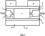
- pulse dampening and degassing device 50 is shown. As a fluid flows in the direction of the arrows shown in FIG. 1 and through said device 50, device 50 dampens fluid pulses with a membrane 11 that expands and contracts in relation to the increases and decreases in fluid pressure (e.g ., the pulses in the fluid).
- Device 50 may be embodied in a variety of configurations, and is illustrated in FIG. 1 as a representative simplified embodiment.
- Device 50 includes a fluid input port 1 and a fluid output port 5, which are connected by fluid channels 2, 4.
- Located between the fluid channels 2, 4 is a dampening and degassing chamber 3.
- the dampening and degassing chamber 3 is also located between and partially defined by a dampening membrane 11 and a degassing membrane 12.
- the dampening membrane 11 and degassing membrane 12 extend the length of the dampening and degassing chamber 3.
- dampening membrane 11 defines the top boundary of the dampening and degassing chamber 3.
- the dampening membrane 11 is secured to one side of the body 9 of the dampening device 50 by a top cover 13.
- Degassing membrane 12 defines the bottom boundary of the dampening and degassing chamber 3 as shown in FIG. 1 .
- the degassing membrane 12 is secured to the dampening device 50 by a bottom cover 14. A fluid flows through the fluid input port 1, fluid channel 2, through the dampening and degassing chamber 3, fluid channel 4, and the fluid output port 5 in the direction of the arrows shown in FIG. 1 .
- tubing or other fluid conveyance means may be attached to the inlet port 1 and to the outlet port 5 of the device 50, and may be sealingly attached to ports 1 and 5 by conventional means, such as a fitting assembly consisting of tubing, a nut and a ferrule or the like.
- a fitting assembly consisting of tubing, a nut and a ferrule or the like.
- the selection of the tubing, nut and ferrule or other fitting assembly or connection means may be chosen based on the intended application of the device 50, such as those involving corrosive chemicals as the fluid, those involving high or low pressures of the fluid, those involving high or low flow rates for the fluid, and the like.
- one of the advantages of the device 50 is that it can be adapted and used in a wide variety of applications.
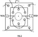
- FIG. 2 A top view of the device 50 is illustrated in FIG. 2 .
- the same numerals are used in the Figures throughout this disclosure to indicate the same features, although the Figures may show alternative embodiments.
- the interior features of the dampening device 50- namely the fluid inlet port 1, fluid channels 2, 4, dampening and degassing chamber 3, and fluid outlet port 5 -are enclosed within the device 50 by the body 9 and may not be visible from a top view of said device 50. If, however, device 50 comprises a transparent or translucent top cover 13, additional details in body 9 can be visible.
- Device 50 may include a plurality of mounting holes 7, which can be provided to allow the dampening device 50 to be mounted in various orientations and to a variety of devices (not shown in FIG. 2 ).
- the device 50 may be mounted and secured to a liquid chromatography device by nuts, bolts, or screws located in one or more of holes 7.
- Device 50 may further include a plurality of bolt holes 8, which are provided to help secure the components of the device 50 together.
- these bolt holes 8 may be in a circular configuration, as shown in FIG. 2 .
- these bolt holes 8 may be in an elliptical or other configuration.
- the configuration of the bolt holes may be varied depending on the shape of the dampening and degassing chamber 3 in a particular embodiment.
- bolt holes 8 it will be understood that the holes 8 can be used with other attaching means, such as nuts or screws.
- body 9, top cover 13, and bottom cover 14 can be secured together by other securing means, such as by adhesives, glues, resins, clamps, and so forth.
- the dampening and degassing chamber 3 may be fabricated with any desired shape.
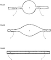
- the shape of the chamber when viewed from above in a planar view may have a substantially circular shape, as shown in FIG. 5A .
- a circular shape maximizes the ratio of the dampening power of the device 50 -a function of the smallest unsupported dimension of the dampening membrane 11 -to the internal volume of the dampening and degassing chamber 3.
- An alternative embodiment has a chamber that when viewed from above in a planar view, constitutes a long, tortuous-shape. (such as is shown in FIG. 5C ).
- a tortuous path can be serpentine or diagonal in shape, or may include portions that are straight, serpentine from a longitudinal axis, diagonal from the longitudinal axis, and the like.
- Such a shape for chamber 3 can be swept very cleanly, but provides extremely limited dampening capabilities, relative to a circular chamber.
- an eye-shaped dampening and degassing chamber 3 (such as is shown in FIG. 5B ) may be used.
- Such shapes as a lens or vesica piscis, or variations on either, may be considered substantially eye-shaped for purposes of this disclosure.
- An eye-shaped chamber 3 may be advantageous because it may in some applications provide good dampening performance, while at the same time provide better sweeping capabilities than a circular shape.
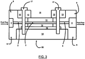
- FIG. 3 shows a detailed cross-sectional view of another embodiment of the device 50.
- the components of the device 50 shown in FIG. 3 may be embodied in a variety of configurations, only one of which is illustrated in FIG. 3 .
- the fluid input port 1, fluid channels 2, 4, and the fluid output port 5 are formed in a body 9, and the body 9 may be made of any suitable material, which may be selected depending in part on the fluid to be used in one or more intended applications.
- the body 9 may be made of, for example, thermoplastics such as acrylic or polyetheretherketone (PEEK).
- Body 9 may be made of other materials, including other plastics, metals, or ceramics.
- body 9 may be made of an acrylic plastic.
- body 9 When fluids containing harsh or corrosive chemicals are used for the fluid, body 9 may be made of high-performance thermoplastics such as, for example, any one of the following: a cyclic-olefin-polymer, co-polymers, polysulfone, polyphenylsulfone, PEEK, or polytetrafluoroethylene (PTFE).
- a cyclic-olefin-polymer such as, for example, any one of the following: a cyclic-olefin-polymer, co-polymers, polysulfone, polyphenylsulfone, PEEK, or polytetrafluoroethylene (PTFE).
- PTFE polytetrafluoroethylene
- Dampening membrane 11 is made of a material which deforms elastically in response to changes in fluid pressure.
- the material to be used for the dampening membrane 11 will vary depending on the range of expected fluid pressures and the chemical compatibility of the dampening membrane 11 material with the fluid to be used in one or more intended applications.
- Dampening membrane 11 may be made of, for example, silicone rubber, thermoplastic vulcanizate (e.g., SANTOPRENE), fluoropolymer elastomer (e.g., VITON), perfluoroelastomer (e.g., KALREZ), biocompatible materials (e.g., PHARMED), polyurethane, natural rubber, neoprene, and/or ethylene propylene diene monomer (EPDM) rubber.
- thermoplastic vulcanizate e.g., SANTOPRENE
- fluoropolymer elastomer e.g., VITON
- perfluoroelastomer e.g., KALREZ
- biocompatible materials e.g., PHARMED
- polyurethane natural rubber
- neoprene neoprene
- EPDM ethylene propylene diene monomer
- dampening membrane 11 may be made of EPDM, fluoropolymer elastomer (e.g ., VITON), perfluoroelastomer (e.g., KALREZ), biocompatible materials (e.g., PHARMED), or other rubber material appropriate for contact with the fluid(s) intended for one or more uses.
- Degassing membrane 12 may be made of any one or more of a variety of non-porous, gas-permeable materials.
- Degassing membrane 12 may be made of, for example, silicone rubber or polytetrafluoroethylene (e.g ., TEFLON AF2400).
- the material or materials used for the degassing membrane 12 can be selected based on knowledge of the likely expected fluid or fluids to be passed through the device 50 in one or more intended applications and the expected gas(es) contained in the fluid or fluids to be used and the corresponding permeability necessary for the degassing membrane 12 to better allow said gas(es) to flow out of the dampening and degassing chamber 3.
- the degassing membrane 12 may be a stand-alone membrane or may be a composite structure comprising multiple materials, such as a membrane - containing carbon nanotubes which is non-porous or a hydrophobic porous support structure.
- the degassing membrane 12 may be made of an aerosol-applied non-porous, but highly permeable material, such as that described in expired U.S. Patent No. 5,238,471 assigned to E.I. Du Pont De Nemours and Company, which is hereby incorporated by reference as if fully set forth herein.
- Said non-porous material such as TEFLON AF 2400 and other highly permeable non - porous polymers may be made by coating such permeable polymers onto a porous fibrillated polymer support structure 16 (e.g ., polyvinylidene fluoride or polypropylene) as is shown in FIG. 3 .
- a porous fibrillated polymer support structure 16 e.g ., polyvinylidene fluoride or polypropylene
- a thin porous support structure 16 is located between the degassing membrane 12 and the bottom cover 14. Support structure 16 can allow gases to flow more freely through the degassing membrane 12.
- Support structure 16 may be made of, for example, a thermoplastic mesh, such as the woven PEEK material PEEKTEX, or any other porous substrate that can provide mechanical support to the degassing membrane while at the same time allowing gases to pass freely through it.
- a thermoplastic mesh such as the woven PEEK material PEEKTEX, or any other porous substrate that can provide mechanical support to the degassing membrane while at the same time allowing gases to pass freely through it.
- the degassing membrane 12 can be a porous de-bubbling membrane instead of a non-porous membrane.
- the degassing membrane 12 can be referred to as a de-bubbling membrane.
- a de-bubbling membrane is more effective than a non-porous membrane at removing physical gas bubbles from a fluid.
- gas bubbles can be removed from the fluid and move through the membrane by the solution-diffusion mechanism.
- gas bubbles can be removed from the fluid and move through the membrane pores through Knudsen diffusion.
- the de-bubbling membrane may be made of, for example, fibrillated polytetrafluoroethylene (PTFE) TEFLON or fibrillated polypropylene.
- PTFE polytetrafluoroethylene
- the type of material to be used for the de-bubbling membrane will usually depend on the expected type of fluid or fluids to be passed through the device 50 and the anticipated gas bubbles to be removed in one or more intended applications. It will be appreciated that porous materials which act through Knudsen diffusion must resist penetration through the pore structure by the fluid being debubbled. Usually, these fluids are aqueous which may contain organic modifiers.
- the selection of the type of porous material can be determined using the bubble point method using well understood techniques such as ASTM F316 - 03 (2011) as applied to the target liquid or range of liquids.
- the performance of the de-bubbling membrane typically decreases for fluids with low surface tensions.
- the top cover 13 defines a cavity 15, which allows the dampening membrane 11 to extend upwards in response to increased fluid pressure within the dampening and degassing chamber 3.
- a lid 21 can be placed above the dampening membrane 11 and in a cavity formed in the top cover 13.
- a lid 21 is secured to the top cover 13, body 9, and bottom cover 14, such as by screws 17, which are threaded through bolt holes 8.
- the lid 21 can be secured to top cover 13 by other securing means, such as bolts, nuts, glue, adhesives, resins, clamps, and so forth.
- said lid 21 has a substantially spherically-contoured, concave lower surface 23.
- Said lid 21 also may include at least one vent hole 22, which allows for air to escape as the membrane 11 expands.
- vent holes 22 may be used, since a single vent hole 22 may be occluded by an upwardly extended dampening membrane 11 (and, hence, may prevent air from escaping).
- a port 24 is connected to an air channel 25 and is located below the degassing membrane 12 and the support structure 16. Said port 24 and air channel 25 facilitate degassing and de-bubbling of a fluid by allowing for entrained gases in the fluid that pass through the degassing membrane 12 to escape the device 50.
- a vacuum pump for example (not shown in FIG. 4 ), if desired may be attached to said port 24 and air channel 25 to help remove gases from the degassing membrane 12.
- the device 50 may be configured in ways other than the configurations illustrated in FIGS. 1-5 .
- a pump (not shown) may be attached to the fluid input port 1, so as to help increase the pressure differential such as may be useful to more quickly achieve degassing and/or de-bubbling of a fluid.
- a vacuum may be attached to the fluid output port 5 to perform the same function.
- the fluid channels 2, 4 may be angled relative to the horizontal plane of the device 50.
- the lid 21, top block 13, body 9, and bottom block 14 may be joined by clips, clamps, glue, other adhesives, or a heat-sealable plastic instead of by screws 17 threaded through bolt holes 8.
- Another alternative embodiment of the present disclosure includes the use of the device 50 with a membrane 12 selected to allow a gas to be introduced into the fluid moving through the device 50, instead of allowing for the removal of a gas from the fluid.
- a pump and/or vacuum could be used to create a pressure differential designed to push or force a gas through a permeable membrane chosen to allow the gas to pass through it and into the fluid.
- a restrictive element may be connected to the port 5 of device 50 so that back-pressure increases as the flow rate of a fluid through the device 50 increases.
- a restrictive element can be provided by a small orifice, a long tube with a relatively small inner diameter through which the fluid passes, or any other device that provides increasing back-pressure when the flow rate of the fluid moving through the restrictive element increases.
- Pulse dampeners and degassers and/or de-bubblers in accordance with the present disclosure can be used in a wide variety of applications.
- the devices of the present disclosure can be used in systems like an analytical instrument system (e.g ., liquid or gas chromatography, ion chromatography, mass spectrometry, micro chromatography, biochemical detection, biological sensing, drug discovery, drug delivery, molecular separation, proteomics, opto-fluidics, and the like), in vitro diagnostic systems including systems that do testing or analysis of blood, urine, DNA or the like, in systems used for other medical and healthcare applications, and in systems used in industrial applications, such as those in which food products, potable liquids (e.g ., milk, water, soft drinks, alcoholic beverages, orange juice, lemonade, and other drinks), air, other liquids, or other fluids are pumped and/or tested.
- an analytical instrument system e.g ., liquid or gas chromatography, ion chromatography, mass spectrometry,
- a device having a restrictive element that provides a hydraulic resistance of about 0.17 MPa (25 pounds per square inch) per milliliter per minute of water may be used for applications in which the fluid is under a pressure of from 0 to 0.69 MPa (0 to 100 pounds per square inch) or so, and the fluid flows at a flow rate in the range of 0 to 1000 microliters per minute or so.
- the device 50 in accordance with one of the embodiments of the present disclosure could typically have an allowed pulse size of from 0 to 50 microliters or so, and have a liquid volume in the chamber 3 of from 100 to 1000 microliters or so.
- Such a device 50 would reduce the amplitude of the pulses by from 10% to 95% or so, depending upon the dampening membrane thickness, area, and durometer.
- the same device would be expected to enable 200 microliters of air to be purged from the chamber 3, in from one to ten minutes, depending on the area and efficiency of the degassing membrane, and the pressure difference between the inner and outer sides of the degassing membrane.
- this is just one example of a specific embodiment; the present disclosure is expected to find use in a wide variety of applications and situations, not just those with these particular pressure, flow rate, and size specifications.
- peristaltic and piston pumps often are used in systems to pump a fluid through the system.
- Such conventional peristaltic and piston pumps can generate unwanted fluctuations in the pressure of the fluid as it flows from the pump.
- a device 50 of the present disclosure can be successfully used in connection with pumps which may generate pressure fluctuations, including peristaltic and piston pumps, as well as other positive displacement pumps such as gear, membrane, screw, syringe, diaphragm, and impeller, pumps.
- peristaltic and piston pumps as well as other positive displacement pumps such as gear, membrane, screw, syringe, diaphragm, and impeller, pumps.
- other types of pumps such as pressure-driven and electroosmotic pumps tend to be less pulsatile
- the present invention might certainly be used with such pumps as well, to reduce or eliminate any residual pulsations that might be present on their outputs.
- pulse dampeners and degassers and/or de-bubbler devices like those shown and described above can vary as to size, shape, and dimensions, and can vary as to the materials used for the various components and features as may be desired for one or more anticipated applications.
- the chamber may be circular, elliptical, or shaped like an eye or a cylindrical shape as shown in FIGs. 5A, 5B, and 5C , or may have some other shape as may be desired for a given application for which the device is intended.
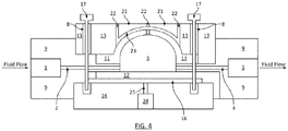
- any or all of these shapes may be used with a hemispherical shape of the dampening chamber 3 as shown in FIG. 4 or some other shape as may be desired for a particular intended application of the device.
- the pulse dampener and degasser and/or de-bubbler device of the present disclosure has a number of advantages.
- the device 50 of the present disclosure does not require complex mechanical or electrical systems as part of a feedback or control mechanism for dampening pulses, nor does it require complex mechanical or electrical systems or components for degassing or de-bubbling functions.
- the device 50 of the present disclosure can be manufactured more easily and more cheaply and is believed to be more durable and easier to maintain.
- the device 50 of the present disclosure has only one chamber that must be filled with liquid, and hence minimizes the volume of liquid that must be used to prime the device, relative to conventional approaches, which require separate dampeners and degassers.
- the invention achieves this, while still providing excellent dampening and degassing and/or de-bubbling characteristics across a wide range of pressures and flow rates.
Landscapes
- Chemical & Material Sciences (AREA)
- Chemical Kinetics & Catalysis (AREA)
- Engineering & Computer Science (AREA)
- General Engineering & Computer Science (AREA)
- Mechanical Engineering (AREA)
- Degasification And Air Bubble Elimination (AREA)
- Separation Using Semi-Permeable Membranes (AREA)
- Pipe Accessories (AREA)
Description
- N/A
- The present disclosure relates generally to devices for dampening fluid pulses, and degassing and de-bubbling devices for removing unwanted gases and/or bubbles, in fluid systems such as analytical instrument systems, and, more specifically, to devices which can dampen fluid pulses and also remove one or more gasses and/or remove bubbles from a fluid, and methods and apparatus relating to the same.
- It is known that pressure variations or pulses may occur when fluids are pumped through conduits. These pressure variations and the resulting mechanical vibrations can disrupt the constant flow of the fluid and cause damage and wear to the pipes and connections. Moreover, such pressure variations can disrupt or ruin downstream applications, which may depend on smooth, steady flow for their proper function. To address these problems, pulse dampeners have been developed to reduce or eliminate pulsations and vibrations in the fluids as they are pumped through pressurized systems.
- Applications for pulse dampeners include, for example, liquid chromatography, where pulses in fluid flow can obscure chromatographic analysis, as well as in other applications such as other analytical instrument systems, including flow cytometry, urinalysis and hematology analyzers, chemical analysis systems, flow cells used in molecular analysis, and other applications in which concentration is measured as a function of time.
- Conventional pulse dampening systems exist, and take a variety of forms. One such method uses air and air pressure to try to counteract and compensate for the pressure exerted by a pressurized fluid moving through the dampener. Conventional pulse dampeners or surge suppressors that do not use elastic membranes have incorporated air chambers such that the fluid being pumped through the conduit is allowed to compress the air in the air chamber and occupy a greater proportion of the volume of the chamber as the fluid pressure increases. When the fluid pressure decreases, the air in the chamber expands and returns some of the fluid from the chamber to the conduit system. A problem with the above approach using one or more air chambers that communicate with the fluid channel, however, is that some of the air will likely dissolve into the fluid being pumped, thereby reducing the volume of air in the chamber and potentially affecting the composition of the fluid being pumped.
- An alternative approach that reduces this problem is to use a dampening membrane which separates the fluid being pumped through the conduit system from an air chamber used to compensate for the fluid pressure. In such systems, the fluid exerts pressure on the membrane, causing it to expand toward the air pressure chamber, and the air in the chamber pushes back on the membrane to compensate for that pressure and membrane displacement. Conventional pulse dampeners that use this method may use a closed air chamber with a static amount of air. However, experience teaches that just about every membrane is at least somewhat gas-permeable - particularly when the membrane is thin, as is often desired to achieve good dampening performance. Thus, this approach often results in the loss of air from the air chamber, and the undesirable gasification of the liquid being pumped.
- An alternative to using an air-filled chamber to provide the restoring force on the liquid, is to use alternative means, such as a compressible liquid, a spring, or a thick, but squishy piece of rubber or foam. An example of such a device is that disclosed in
U.S. Patent No. 4,629,562 , titled "Pulse Dampener" and issued to Kercher on December 16, 1986. The Kercher patent explains that a pulse dampener may be used in a liquid chromatography system and teaches the use of a chemically inert diaphragm and a unitized plug which has two portions, each of which has different compressibility characteristics. However, in such a device, gasses may still find their way into the liquid through leaks in the system, by incomplete priming of the device, or by introduction of air bubbles into the fluid flow itself. Once introduced into such a dampener, such air-bubbles can be extremely hard to remove, and they influence the performance of the dampener in unpredictable ways. - Another example can be found in
U.S. Patent No. 4,548,240 , titled "Hydraulic Pulse Dampener and Employing Stiff Diaphragm and Nesting Member," and issued to Graham on October 22, 1985. Graham teaches an example of a hydraulic pulse dampener which uses liquid to dampen pulses in a relatively high-pressure environment. However, Graham does not provide for any degassing capability. Likewise,U.S. Patent No. 4,222,414 , titled "Pulse Dampener for High Pressure Liquid Chromatography," and issued to Achener on September 16, 1980, andU.S. Patent No. 4,234,427 , titled "Pulse Dampener," and issued to Boehme on November 18, 1980, both disclose hydraulic pulse dampeners for use in relatively high-pressure environments, but the apparatus disclosed in both Achener and Graham lack any degassing or de-bubbling capabilities. - Air bubbles trapped in a dampener can result in several undesirable consequences. First, the presence of bubbles can affect the dampening power of the pulse dampener. The dampening power of the pulse dampener can vary in direct proportion to the varying size of the bubbles generated by or introduced into the system, and therefore the system may not uniformly dampen fluid pulses. In such situations, the dampening ability may be variable and unpredictable. Second, bubbles may unintentionally exit the pulse dampening system and travel downstream in the system. In some applications, such as liquid chromatography, the presence of bubbles in the fluid stream is undesirable. Third, gas bubbles trapped in a fluid pulse dampening system may cause gas buildups within the system, thereby reducing the ability to cleanly and fully sweep a fluid through the system.
- The problem of dissolved gas or bubbles within pulse dampening systems has met with some efforts at resolution, but these results and approaches have several drawbacks and limitations. For example,
U.S. Patent No. 5,904,181 , titled "Pulse Dampening Device," and issued to Tooma et al. on May 18, 1999, discloses a pulsation dampening device with a horizontal shape and with fluid inlet and outlet ports configured so as to minimize air bubbles from becoming trapped within a fluid. However, Tooma et al. fails to disclose or provide a system for extracting air bubbles that do become trapped. - Similarly,
U.S. Patent No. 6,675,835 , titled "Elliptical Tubing in Degassing and Pulsation Damper Application," issued to Gerner et al. on January 13, 2004 discloses a flow-dampening and degassing apparatus which uses a gas-permeable, non-porous, elliptical-shaped tube disposed within a vacuum chamber. Besides the cost and complexity of requiring a vacuum chamber, Gerner et al. has the further limitation of having a membrane which must perform both the dampening and degassing functions. Thus, the functions of the two membranes cannot be separately optimized to account for different types of fluid by, for example, the use of different materials, shapes, or sizes for the membranes. - Likewise,
U.S. published patent application No. 2003/0041911 , titled "Burdoin (sic) Tubing in Degassing and Pulse Dampener Applications," filed on behalf of Gerner et al., discusses integrating a degasser function and a dampening function, but do so using a Bourdon tube as the dampening element and thus require a more complex dampening system. In addition, because the degassing tube and the dampening tube in the Gerner et al. patent application are one-and-the-same, one cannot independently optimize the dampening characteristics and the degassing characteristics. - The foregoing U.S. patents with Nos.
4,548,240 ,4,222, 414 ,4,234, 427 ,5,904,181 , and6,675,835 , and U.S. published patent application No.2003/0041911 , are hereby incorporated by reference as if fully set forth herein.WO 2001/031333 discloses a degassing device. - The use of both a conventional pulse dampener and a conventional degasser or de-bubbler in a given system remains a possibility, but also involves limitations and drawbacks. For example, such an approach involves the use of two separate components in a system, thus making the system more complex, and introducing more internal volume into the system. Moreover, this approach involves the use of more fluid connections (and thus more work for an operator and greater chance for leaks) and also additional costs due to the use of two components.
- The invention is according to
claim 1. The degassing membrane in one or more embodiments may comprise a substantially non-porous material, or may comprise a substantially porous material. The degassing membrane comprises one or more materials selected from the group consisting of: silicone rubber, polytetrafluoroethylene (e.g., TEFLON AF200), and fibrillated polymers. In one embodiment, the device further comprises a porous support, wherein at least a portion of said support is located between said degassing membrane and a bottom side of said body. The body of the device further comprises a top body portion and a bottom body portion, and wherein said top body portion and said bottom body portion are secured together. The device may further comprise a lid located within a cavity in said body above at least a portion of said dampening membrane, wherein said lid comprises a spherically-shaped lower surface portion facing a portion of said dampening membrane. In this particular embodiment, the lid may comprise at least one vent providing fluid communication between the cavity above said dampening membrane and an exterior portion of said body. In certain embodiments, either or both of the dampening and the degassing membranes maintain a sealed connection to said body when the pressure of a fluid in the chamber is less than or equal to 69, 138, 207, 276, 345, 414, 483, 552, 621, and/or 689 kPa (respectively 10 psi, 20 psi, 30 psi, 40 psi, 50 psi, 60 psi, 70 psi, 80 psi, 90 psi, and/or 100 psi) or so. - Briefly stated, these and numerous other features, objects and advantages of the present disclosure will become readily apparent upon a reading of the detailed description, claims and the drawings set forth herein. These features, objects and advantages are generally accomplished by providing a device having a dampening and degassing chamber of a certain shape and by having a fluid input port and a fluid output port positioned relative to the dampening and degassing chamber in a way that helps maximize the dampening power of the dampening membrane, minimize the volume of the dampening and degassing chamber, maximize the surface area of the degassing membrane, and maximize the ability to sweep fluids out of the dampening device, all while providing a device that is easy to use because it does not require extra connections and also tends to be less expensive because it requires less components and is easier, faster, and cheaper to manufacture.
-
-
FIG. 1 is a cross-sectional side view of a dampening and degassing device in accordance with an embodiment of the present disclosure. -
FIG. 2 is a top view of the device ofFIG. 1 . -
FIG. 3 is a cross-sectional side view in accordance with an embodiment of the present disclosure. -
FIG. 4 is a cross-sectional side view of one embodiment of a device in accordance with another embodiment of the present disclosure. -
FIGS. 5A, 5B, and 5C are top views of alternative embodiments of a chamber in a device in accordance with the present disclosure. - Referring first to
FIG. 1 , pulse dampening anddegassing device 50 is shown. As a fluid flows in the direction of the arrows shown inFIG. 1 and through saiddevice 50,device 50 dampens fluid pulses with amembrane 11 that expands and contracts in relation to the increases and decreases in fluid pressure (e.g., the pulses in the fluid). -
Device 50 may be embodied in a variety of configurations, and is illustrated inFIG. 1 as a representative simplified embodiment.Device 50 includes afluid input port 1 and afluid output port 5, which are connected byfluid channels fluid channels degassing chamber 3. As shown inFIG. 1 , the dampening anddegassing chamber 3 is also located between and partially defined by a dampeningmembrane 11 and adegassing membrane 12. InFIG. 1 , the dampeningmembrane 11 and degassingmembrane 12 extend the length of the dampening anddegassing chamber 3. As shown inFIG. 1 , dampeningmembrane 11 defines the top boundary of the dampening anddegassing chamber 3. To prevent fluid from leaking out of thechamber 3, the dampeningmembrane 11 is secured to one side of thebody 9 of the dampeningdevice 50 by atop cover 13. Degassingmembrane 12 defines the bottom boundary of the dampening anddegassing chamber 3 as shown inFIG. 1 . To prevent fluid from leaking out of thechamber 3, the degassingmembrane 12 is secured to the dampeningdevice 50 by abottom cover 14. A fluid flows through thefluid input port 1,fluid channel 2, through the dampening anddegassing chamber 3,fluid channel 4, and thefluid output port 5 in the direction of the arrows shown inFIG. 1 . - Although not shown, it will be understood by those of skill in the art that tubing or other fluid conveyance means may be attached to the
inlet port 1 and to theoutlet port 5 of thedevice 50, and may be sealingly attached toports device 50, such as those involving corrosive chemicals as the fluid, those involving high or low pressures of the fluid, those involving high or low flow rates for the fluid, and the like. As further described below, it will be appreciated that one of the advantages of thedevice 50 is that it can be adapted and used in a wide variety of applications. - A top view of the
device 50 is illustrated inFIG. 2 . Generally, the same numerals are used in the Figures throughout this disclosure to indicate the same features, although the Figures may show alternative embodiments. The interior features of the dampening device 50-namely thefluid inlet port 1,fluid channels degassing chamber 3, and fluid outlet port 5-are enclosed within thedevice 50 by thebody 9 and may not be visible from a top view of saiddevice 50. If, however,device 50 comprises a transparent or translucenttop cover 13, additional details inbody 9 can be visible.Device 50 may include a plurality of mountingholes 7, which can be provided to allow the dampeningdevice 50 to be mounted in various orientations and to a variety of devices (not shown inFIG. 2 ). For example, thedevice 50 may be mounted and secured to a liquid chromatography device by nuts, bolts, or screws located in one or more ofholes 7.Device 50 may further include a plurality ofbolt holes 8, which are provided to help secure the components of thedevice 50 together. In one embodiment, thesebolt holes 8 may be in a circular configuration, as shown inFIG. 2 . In another embodiment, thesebolt holes 8 may be in an elliptical or other configuration. The configuration of the bolt holes may be varied depending on the shape of the dampening anddegassing chamber 3 in a particular embodiment. Although referred to herein as bolt holes 8, it will be understood that theholes 8 can be used with other attaching means, such as nuts or screws. Moreover, it will be understood and appreciated thatbody 9,top cover 13, andbottom cover 14 can be secured together by other securing means, such as by adhesives, glues, resins, clamps, and so forth. - The dampening and
degassing chamber 3 may be fabricated with any desired shape. In one embodiment, the shape of the chamber when viewed from above in a planar view may have a substantially circular shape, as shown inFIG. 5A . A circular shape maximizes the ratio of the dampening power of the device 50-a function of the smallest unsupported dimension of the dampening membrane 11-to the internal volume of the dampening anddegassing chamber 3. However, experience has shown that it can be difficult to completely sweep fluid through a circular chamber. Such sweeping may be desirable, for example, when changing the type of fluid being passed through the dampening anddegassing chamber 3 in repeated use of thedevice 50. Failure to fully sweep fluid out of saidchamber 3 may leave behind carryover fluid from a prior use that may contaminate or otherwise affect the next use. - An alternative embodiment has a chamber that when viewed from above in a planar view, constitutes a long, tortuous-shape. (such as is shown in
FIG. 5C ). Although shown inFIG. 5C as a substantially straight flow path, a tortuous path can be serpentine or diagonal in shape, or may include portions that are straight, serpentine from a longitudinal axis, diagonal from the longitudinal axis, and the like. Such a shape forchamber 3 can be swept very cleanly, but provides extremely limited dampening capabilities, relative to a circular chamber. - Between these two extremes, there exist any number of chamber shapes that may be fabricated, with a desire to maximize dampening performance, reduce chamber internal volume, and enable clean fluid exchange. In general, there is a trade-off between the dampening performance-to-internal volume ratio, and the ability to sweep the fluid path. A compromise between these desires may therefore be the best solution. As one example, in another embodiment, an eye-shaped dampening and degassing chamber 3 (such as is shown in
FIG. 5B ) may be used. Such shapes as a lens or vesica piscis, or variations on either, may be considered substantially eye-shaped for purposes of this disclosure. An eye-shapedchamber 3 may be advantageous because it may in some applications provide good dampening performance, while at the same time provide better sweeping capabilities than a circular shape. - It will be understood by those skilled in the art that other shapes are also possible for
chamber 3. -
FIG. 3 shows a detailed cross-sectional view of another embodiment of thedevice 50. The components of thedevice 50 shown inFIG. 3 may be embodied in a variety of configurations, only one of which is illustrated inFIG. 3 . Thefluid input port 1,fluid channels fluid output port 5 are formed in abody 9, and thebody 9 may be made of any suitable material, which may be selected depending in part on the fluid to be used in one or more intended applications. Thebody 9 may be made of, for example, thermoplastics such as acrylic or polyetheretherketone (PEEK).Body 9 may be made of other materials, including other plastics, metals, or ceramics. For applications in which aqueous fluids are to be used, for example,body 9 may be made of an acrylic plastic. When fluids containing harsh or corrosive chemicals are used for the fluid,body 9 may be made of high-performance thermoplastics such as, for example, any one of the following: a cyclic-olefin-polymer, co-polymers, polysulfone, polyphenylsulfone, PEEK, or polytetrafluoroethylene (PTFE). When fluids are to be passed through thedevice 50 at high pressures,body 9 may be made of ceramic or metals such as, for example, stainless steel. - Dampening
membrane 11 is made of a material which deforms elastically in response to changes in fluid pressure. The material to be used for the dampeningmembrane 11 will vary depending on the range of expected fluid pressures and the chemical compatibility of the dampeningmembrane 11 material with the fluid to be used in one or more intended applications. Dampeningmembrane 11 may be made of, for example, silicone rubber, thermoplastic vulcanizate (e.g., SANTOPRENE), fluoropolymer elastomer (e.g., VITON), perfluoroelastomer (e.g., KALREZ), biocompatible materials (e.g., PHARMED), polyurethane, natural rubber, neoprene, and/or ethylene propylene diene monomer (EPDM) rubber. When fluids containing harsh or corrosive chemicals (e.g., fluids that are acidic or basic) are to be used for the fluid, dampeningmembrane 11 may be made of EPDM, fluoropolymer elastomer (e.g., VITON), perfluoroelastomer (e.g., KALREZ), biocompatible materials (e.g., PHARMED), or other rubber material appropriate for contact with the fluid(s) intended for one or more uses. - As shown in
FIG. 3 , screws 17 are threaded through the bolt holes 8, which securely attach thetop cover 13, thebottom cover 14, and thebody 9 together. In this embodiment, this secure attachment also holds the dampeningmembrane 11 in place and against thebody 9, so that a fluid-tight seal at the top of the dampening anddegassing chamber 3 is provided bymembrane 11. Likewise, this assembly secures the degassingmembrane 12 in place and against thebody 9, so that a fluid-tight seal at the bottom of the dampening anddegassing chamber 3. It will be understood that fluid-tight seals may also be created by placing gaskets (not shown inFIG. 3 ) between the dampeningmembrane 11 and thebody 9, and/or between the degassingmembrane 12 and thebody 9. These gaskets may be made of, for example, TEFLON or silicone. - Degassing
membrane 12 may be made of any one or more of a variety of non-porous, gas-permeable materials. Degassingmembrane 12 may be made of, for example, silicone rubber or polytetrafluoroethylene (e.g., TEFLON AF2400). The material or materials used for thedegassing membrane 12 can be selected based on knowledge of the likely expected fluid or fluids to be passed through thedevice 50 in one or more intended applications and the expected gas(es) contained in the fluid or fluids to be used and the corresponding permeability necessary for thedegassing membrane 12 to better allow said gas(es) to flow out of the dampening anddegassing chamber 3. It will be understood that the degassingmembrane 12 may be a stand-alone membrane or may be a composite structure comprising multiple materials, such as a membrane - containing carbon nanotubes which is non-porous or a hydrophobic porous support structure. As an exemplary embodiment, the degassingmembrane 12 may be made of an aerosol-applied non-porous, but highly permeable material, such as that described in expiredU.S. Patent No. 5,238,471 assigned to E.I. Du Pont De Nemours and Company, which is hereby incorporated by reference as if fully set forth herein. Said non-porous material such as TEFLON AF 2400 and other highly permeable non - porous polymers may be made by coating such permeable polymers onto a porous fibrillated polymer support structure 16 (e.g., polyvinylidene fluoride or polypropylene) as is shown inFIG. 3 . In the embodiment shown inFIG. 3 , a thinporous support structure 16 is located between the degassingmembrane 12 and thebottom cover 14.Support structure 16 can allow gases to flow more freely through the degassingmembrane 12.Support structure 16 may be made of, for example, a thermoplastic mesh, such as the woven PEEK material PEEKTEX, or any other porous substrate that can provide mechanical support to the degassing membrane while at the same time allowing gases to pass freely through it. - In another embodiment, the degassing
membrane 12 can be a porous de-bubbling membrane instead of a non-porous membrane. Thus, in such an embodiment, the degassingmembrane 12 can be referred to as a de-bubbling membrane. A de-bubbling membrane is more effective than a non-porous membrane at removing physical gas bubbles from a fluid. With a non-porous, de-bubbling membrane, gas bubbles can be removed from the fluid and move through the membrane by the solution-diffusion mechanism. However, with a porous de-bubbling membrane, gas bubbles can be removed from the fluid and move through the membrane pores through Knudsen diffusion. To achieve de-bubbling, the de-bubbling membrane may be made of, for example, fibrillated polytetrafluoroethylene (PTFE) TEFLON or fibrillated polypropylene. The type of material to be used for the de-bubbling membrane will usually depend on the expected type of fluid or fluids to be passed through thedevice 50 and the anticipated gas bubbles to be removed in one or more intended applications. It will be appreciated that porous materials which act through Knudsen diffusion must resist penetration through the pore structure by the fluid being debubbled. Mostly, these fluids are aqueous which may contain organic modifiers. The selection of the type of porous material can be determined using the bubble point method using well understood techniques such as ASTM F316 - 03 (2011) as applied to the target liquid or range of liquids. The performance of the de-bubbling membrane typically decreases for fluids with low surface tensions. Still referring toFIG. 3 , thetop cover 13 defines acavity 15, which allows the dampeningmembrane 11 to extend upwards in response to increased fluid pressure within the dampening anddegassing chamber 3. - In one embodiment, shown in
FIG. 4 , to prevent the dampeningmembrane 11 from extending upward to such a degree as to cause inelastic stretching or rupture of themembrane 11, alid 21 can be placed above the dampeningmembrane 11 and in a cavity formed in thetop cover 13. As shown inFIG. 4 , alid 21 is secured to thetop cover 13,body 9, andbottom cover 14, such as byscrews 17, which are threaded through bolt holes 8. It will be appreciated by those skilled in the art that thelid 21 can be secured totop cover 13 by other securing means, such as bolts, nuts, glue, adhesives, resins, clamps, and so forth. As shown inFIG. 3 , saidlid 21 has a substantially spherically-contoured, concavelower surface 23. As a fluid passes in the direction of the arrows shown inFIG. 4 through the dampening anddegassing chamber 3, and the dampeningmembrane 11 responds to increases in fluid pressure, the dampeningmembrane 11 will extend upward and may fill the space between themembrane 11 and the spherically-contouredlower surface 23 of thelid 21. Saidlid 21 also may include at least onevent hole 22, which allows for air to escape as themembrane 11 expands. In the embodiment shown inFIG. 4 , for example, multiple vent holes 22 may be used, since asingle vent hole 22 may be occluded by an upwardly extended dampening membrane 11 (and, hence, may prevent air from escaping). - In the embodiment shown in
FIG. 4 , for example, aport 24 is connected to anair channel 25 and is located below the degassingmembrane 12 and thesupport structure 16. Saidport 24 andair channel 25 facilitate degassing and de-bubbling of a fluid by allowing for entrained gases in the fluid that pass through the degassingmembrane 12 to escape thedevice 50. A vacuum pump, for example (not shown inFIG. 4 ), if desired may be attached to saidport 24 andair channel 25 to help remove gases from the degassingmembrane 12. - It will be appreciated that the
device 50 may be configured in ways other than the configurations illustrated inFIGS. 1-5 . In one embodiment, for example, a pump (not shown) may be attached to thefluid input port 1, so as to help increase the pressure differential such as may be useful to more quickly achieve degassing and/or de-bubbling of a fluid. In another embodiment, a vacuum may be attached to thefluid output port 5 to perform the same function. In another embodiment, thefluid channels device 50. In other embodiments, thelid 21,top block 13,body 9, andbottom block 14 may be joined by clips, clamps, glue, other adhesives, or a heat-sealable plastic instead of byscrews 17 threaded through bolt holes 8. Another alternative embodiment of the present disclosure includes the use of thedevice 50 with amembrane 12 selected to allow a gas to be introduced into the fluid moving through thedevice 50, instead of allowing for the removal of a gas from the fluid. In such an embodiment, a pump and/or vacuum could be used to create a pressure differential designed to push or force a gas through a permeable membrane chosen to allow the gas to pass through it and into the fluid. - Although not shown, those skilled in the art will appreciate that the
device 50 can be used with a restrictive element to help generate back-pressure. For example, a restrictive element may be connected to theport 5 ofdevice 50 so that back-pressure increases as the flow rate of a fluid through thedevice 50 increases. A restrictive element can be provided by a small orifice, a long tube with a relatively small inner diameter through which the fluid passes, or any other device that provides increasing back-pressure when the flow rate of the fluid moving through the restrictive element increases. - Pulse dampeners and degassers and/or de-bubblers in accordance with the present disclosure can be used in a wide variety of applications. For example, the devices of the present disclosure can be used in systems like an analytical instrument system (e.g., liquid or gas chromatography, ion chromatography, mass spectrometry, micro chromatography, biochemical detection, biological sensing, drug discovery, drug delivery, molecular separation, proteomics, opto-fluidics, and the like), in vitro diagnostic systems including systems that do testing or analysis of blood, urine, DNA or the like, in systems used for other medical and healthcare applications, and in systems used in industrial applications, such as those in which food products, potable liquids (e.g., milk, water, soft drinks, alcoholic beverages, orange juice, lemonade, and other drinks), air, other liquids, or other fluids are pumped and/or tested. Those skilled in the art will appreciate that pulse dampeners of the present disclosure may be used in still other applications.
- Although it will be apparent that the embodiments of the present disclosure can be used in a wide variety of situations, the following are some specific details regarding potential applications. For example, a device having a restrictive element that provides a hydraulic resistance of about 0.17 MPa (25 pounds per square inch) per milliliter per minute of water, may be used for applications in which the fluid is under a pressure of from 0 to 0.69 MPa (0 to 100 pounds per square inch) or so, and the fluid flows at a flow rate in the range of 0 to 1000 microliters per minute or so. In such an application, the
device 50 in accordance with one of the embodiments of the present disclosure could typically have an allowed pulse size of from 0 to 50 microliters or so, and have a liquid volume in thechamber 3 of from 100 to 1000 microliters or so. Such adevice 50 would reduce the amplitude of the pulses by from 10% to 95% or so, depending upon the dampening membrane thickness, area, and durometer. The same device would be expected to enable 200 microliters of air to be purged from thechamber 3, in from one to ten minutes, depending on the area and efficiency of the degassing membrane, and the pressure difference between the inner and outer sides of the degassing membrane. As noted, this is just one example of a specific embodiment; the present disclosure is expected to find use in a wide variety of applications and situations, not just those with these particular pressure, flow rate, and size specifications. - Those skilled in the art will also appreciate that different applications often use different types of pumping mechanisms, and the pulse dampener and degasser and/or
de-bubbler device 50 like that shown and disclosed herein can be used with different types of pumping mechanisms. For example, conventional peristaltic and piston pumps often are used in systems to pump a fluid through the system. Such conventional peristaltic and piston pumps can generate unwanted fluctuations in the pressure of the fluid as it flows from the pump. Accordingly, adevice 50 of the present disclosure can be successfully used in connection with pumps which may generate pressure fluctuations, including peristaltic and piston pumps, as well as other positive displacement pumps such as gear, membrane, screw, syringe, diaphragm, and impeller, pumps. While other types of pumps, such as pressure-driven and electroosmotic pumps tend to be less pulsatile, the present invention might certainly be used with such pumps as well, to reduce or eliminate any residual pulsations that might be present on their outputs. - Those skilled in the art will also appreciate that pulse dampeners and degassers and/or de-bubbler devices like those shown and described above can vary as to size, shape, and dimensions, and can vary as to the materials used for the various components and features as may be desired for one or more anticipated applications. For example, the chamber may be circular, elliptical, or shaped like an eye or a cylindrical shape as shown in
FIGs. 5A, 5B, and 5C , or may have some other shape as may be desired for a given application for which the device is intended. In addition, any or all of these shapes may be used with a hemispherical shape of the dampeningchamber 3 as shown inFIG. 4 or some other shape as may be desired for a particular intended application of the device. In addition, those skilled in the art will appreciate that the devices disclosed herein shown can be easily adapted for orientations different than those shown and described above for a given intended application if so desired. Thus, references herein to terms such as "top," "bottom, "right," "left," "above," "below," and the like are merely used for convenience with respect to the illustrations in the figures and are not limiting of the scope of the invention. - Those skilled in the art will further appreciate that the pulse dampener and degasser and/or de-bubbler device of the present disclosure has a number of advantages. The
device 50 of the present disclosure does not require complex mechanical or electrical systems as part of a feedback or control mechanism for dampening pulses, nor does it require complex mechanical or electrical systems or components for degassing or de-bubbling functions. Thus, thedevice 50 of the present disclosure can be manufactured more easily and more cheaply and is believed to be more durable and easier to maintain. In addition, thedevice 50 of the present disclosure has only one chamber that must be filled with liquid, and hence minimizes the volume of liquid that must be used to prime the device, relative to conventional approaches, which require separate dampeners and degassers. The invention achieves this, while still providing excellent dampening and degassing and/or de-bubbling characteristics across a wide range of pressures and flow rates. These advantages and still others will be apparent to those skilled in the art in view of the embodiments shown and described in this disclosure. - The foregoing detailed descriptions and disclosure are only illustrative and by way of examples.
Claims (9)
- A device (50) comprising:a body (9) having a first side and a second side, wherein the first side has a first input port (1) and the second side has a second output port (5), and wherein said body (9) has a chamber (3) therein, wherein the chamber (3) is in fluid communication with the first port (1) and the second port (5);a dampening membrane (11) comprising a first material selected from the group consisting of: silicone rubber, fluoropolymer elastomer, perfluoroelastomer, biocompatible materials, polyurethane, rubber, neoprene, ethylene propylene diene monomer rubber, and combinations thereof which deforms elastically in response to changes in fluid pressure, wherein at least a first portion of said dampening membrane defines a top portion of the chamber (3) in said body (9) and at least a second portion of said dampening membrane (11) is sealingly secured to said body (9);a degassing membrane or a de-bubbling membrane (12) comprising a second material selected respectively from the group consisting of: silicone rubber, polytetrafluoroethylene, fibrillated polymers, and combinations thereof, or from the group consisting of: polytetrafluoroethylene, TEFLON, fibrillated polypropylene, and combinations thereof, wherein at least a first portion of said degassing membrane or de-bubbling membrane (12) defines a bottom portion of the chamber (3) in said body (9) and at least a second portion of said degassing membrane or de-bubbling membrane (12) is sealingly secured to said body (9); anda top cover (13) defining a cavity in said body (9) above said dampening membrane (11), wherein the cavity allows the dampening membrane (11) to extend upwards in response to increased fluid pressure within the chamber (3).
- The device (50) according to claim 1 wherein the chamber (3), when viewed from the top, has a substantially circular or oval shape, or wherein the chamber (3) when viewed from the top, is substantially eye-shaped.
- The device (50) according to claim 1 wherein said body (9) comprises a thermoplastic material, or wherein said body (9) comprises a metal, or wherein said body (9) comprises a ceramic.
- The device (50) according to claim 1 wherein said degassing membrane (12) comprises a substantially non-porous material, or wherein said degassing membrane (12) comprises a substantially porous material.
- The device (50) according to claim 1 further comprising a porous support (16), wherein at least a portion of said support (16) is located between said degassing membrane (12) and a bottom side of said body (9).
- The device (50) according to claim 1 wherein said body (9) further comprises a top body portion (13) and a bottom body portion (14), and wherein said top body portion (13) and said bottom body portion (14) are secured together.
- The device (50) according to claim 1 further comprising a lid (21) located within the cavity in said body (9) above at least a portion of said dampening membrane (3), wherein said lid (21) comprises a spherically-shaped lower surface portion facing a portion of said dampening membrane (11), wherein said lid (21) optionally comprises at least one vent providing fluid communication between the cavity above said dampening membrane (11) and an exterior portion of said body (9).
- The device (50) according to claim 1 wherein both said dampening and said degassing membrane (12) maintain a sealed connection to said body (9) when the pressure of a fluid in the chamber (3) is less than or equal to 0.69MPa (100 psi).
- The device (50) according to claim 1 further comprising a plurality of mounting holes in said body (9).
Applications Claiming Priority (2)
| Application Number | Priority Date | Filing Date | Title |
|---|---|---|---|
| US14/684,219 US9764290B2 (en) | 2015-04-10 | 2015-04-10 | Degassing and de-bubbling pulse dampener |
| PCT/US2016/023396 WO2016164161A1 (en) | 2015-04-10 | 2016-03-21 | Degassing, de-bubbling, and dampening device |
Publications (3)
| Publication Number | Publication Date |
|---|---|
| EP3280509A1 EP3280509A1 (en) | 2018-02-14 |
| EP3280509A4 EP3280509A4 (en) | 2018-09-26 |
| EP3280509B1 true EP3280509B1 (en) | 2020-05-27 |
Family
ID=57073355
Family Applications (1)
| Application Number | Title | Priority Date | Filing Date |
|---|---|---|---|
| EP16777036.1A Active EP3280509B1 (en) | 2015-04-10 | 2016-03-21 | Degassing, de-bubbling, and dampening device |
Country Status (5)
| Country | Link |
|---|---|
| US (2) | US9764290B2 (en) |
| EP (1) | EP3280509B1 (en) |
| JP (1) | JP6672330B2 (en) |
| CN (1) | CN107614080B (en) |
| WO (1) | WO2016164161A1 (en) |
Families Citing this family (6)
| Publication number | Priority date | Publication date | Assignee | Title |
|---|---|---|---|---|
| US9764290B2 (en) * | 2015-04-10 | 2017-09-19 | Idex Health & Science Llc | Degassing and de-bubbling pulse dampener |
| CN107035806B (en) * | 2017-05-24 | 2018-09-25 | 西安热工研究院有限公司 | A kind of pulse damper |
| IT201800004751A1 (en) * | 2018-04-20 | 2019-10-20 | HYDROPNEUMATIC DAMPER | |
| RU198489U1 (en) * | 2020-04-09 | 2020-07-13 | Павел Дмитриевич Дуньшин | Damper for damping gas pulsations in the pipeline |
| TWI768379B (en) | 2020-06-19 | 2022-06-21 | 緯創資通股份有限公司 | Presure buffering system and biological culture device |
| JP7529180B2 (en) | 2022-06-27 | 2024-08-06 | Dic株式会社 | Deaeration device |
Family Cites Families (32)
| Publication number | Priority date | Publication date | Assignee | Title |
|---|---|---|---|---|
| US3741692A (en) | 1970-12-17 | 1973-06-26 | Rupp Co Warren | Surge suppressor for fluid lines |
| US4163461A (en) * | 1978-01-23 | 1979-08-07 | Greer Hydraulics, Inc. | High frequency pulse dampener |
| US4234427A (en) | 1979-06-04 | 1980-11-18 | Varian Associates, Inc. | Pulse damper |
| US4222414A (en) | 1979-06-14 | 1980-09-16 | Varian Associates, Inc. | Pulse damper for high-pressure liquid chromatography |
| US4336036A (en) * | 1981-01-08 | 1982-06-22 | Amf Incorporated | Filter and method of making same |
| US4548240A (en) | 1983-04-21 | 1985-10-22 | Varian Associates, Inc. | Hydraulic pulse dampener employing stiff diaphragm and nesting member |
| US4552182A (en) | 1983-04-21 | 1985-11-12 | Varian Associates, Inc. | Hydraulic pulse dampener employing two stiff diaphragms and nesting members |
| US4556087A (en) | 1984-12-20 | 1985-12-03 | Itt Corporation | Pulsation damper |
| US4629562A (en) | 1985-08-06 | 1986-12-16 | Scientific Systems, Inc. | Pulse dampener |
| DE4318553C2 (en) | 1993-06-04 | 1995-05-18 | Daimler Benz Ag | Adaptive hydropneumatic pulsation damper |
| US5651931A (en) | 1994-01-27 | 1997-07-29 | Upchurch Scientific, Inc. | Method of making a biocompatible filter |
| US5472600A (en) | 1995-02-01 | 1995-12-05 | Minnesota Mining And Manufacturing Company | Gradient density filter |
| FR2748953B1 (en) * | 1996-05-24 | 1998-10-02 | Millipore Sa | ELLIPSE-SHAPED FILTRATION UNIT |
| US5904181A (en) | 1997-06-30 | 1999-05-18 | Eastman Kodak Company | Pulsation dampening device |
| JPH11137907A (en) * | 1997-11-11 | 1999-05-25 | Moore Kk | Deaerator |
| GB2344526B (en) | 1999-01-12 | 2001-05-23 | Dumaresq Lucas Alison Jayne | Syringe with filter,and filter therefor |
| WO2002018037A2 (en) * | 2000-08-31 | 2002-03-07 | Millipore Corporation | Gas vent filter construction incorporating a hollow fiber membrane assembly |
| US6675835B2 (en) * | 2001-07-10 | 2004-01-13 | Systec, Inc. | Elliptical tubing in degassing and pulsation dampener application |
| US6942718B1 (en) * | 2002-01-31 | 2005-09-13 | Ball Aerospace & Technologies Corp. | Orientation insensitive combined liquid reservoir and gas/liquid separator |
| US7713331B2 (en) * | 2003-11-05 | 2010-05-11 | Rheodyne, Llc | Axial transfer line degassing |
| WO2005087340A1 (en) | 2004-03-05 | 2005-09-22 | Waters Investments Limited | Frit for high pressure liquid chromotography |
| US20090001019A1 (en) * | 2004-06-03 | 2009-01-01 | Mykrolis Corporation | Fluid Treating Apparatus |
| CN100548428C (en) | 2004-08-19 | 2009-10-14 | 沃特世科技公司 | Be used to carry out equipment, the method and apparatus of separation |
| US7674383B2 (en) | 2005-10-25 | 2010-03-09 | Phenomenex, Inc. | Method and apparatus for packing chromatography columns |
| US8192534B2 (en) * | 2007-10-13 | 2012-06-05 | Neema Hekmat | Open lumen air filtration for liquid lines |
| CN102481494B (en) * | 2009-09-14 | 2014-09-10 | 兰登姆科技有限责任公司 | Apparatus and methods for changing the concentration of gases in liquids |
| JP2013505824A (en) * | 2009-09-24 | 2013-02-21 | ゴア エンタープライズ ホールディングス,インコーポレイティド | Integrity test method for porous filters |
| WO2014039514A2 (en) * | 2012-09-05 | 2014-03-13 | President And Fellows Of Harvard College | Removing bubbles in microfluidic systems |
| US9114331B2 (en) * | 2012-09-28 | 2015-08-25 | Random Technologies Llc | Apparatus and method for degassing liquids |
| WO2014165373A1 (en) * | 2013-04-04 | 2014-10-09 | Surnetics, Llc | Microfluidic products with controlled fluid flow |
| WO2014190258A1 (en) * | 2013-05-23 | 2014-11-27 | The Regents Of The University Of California | Proximal degas driven microfluidic actuation |
| US9764290B2 (en) * | 2015-04-10 | 2017-09-19 | Idex Health & Science Llc | Degassing and de-bubbling pulse dampener |
-
2015
- 2015-04-10 US US14/684,219 patent/US9764290B2/en active Active
-
2016
- 2016-03-21 CN CN201680029820.0A patent/CN107614080B/en active Active
- 2016-03-21 JP JP2017552912A patent/JP6672330B2/en active Active
- 2016-03-21 WO PCT/US2016/023396 patent/WO2016164161A1/en active Application Filing
- 2016-03-21 EP EP16777036.1A patent/EP3280509B1/en active Active
-
2017
- 2017-08-29 US US15/689,887 patent/US10569224B2/en active Active
Non-Patent Citations (1)
| Title |
|---|
| None * |
Also Published As
| Publication number | Publication date |
|---|---|
| CN107614080A (en) | 2018-01-19 |
| EP3280509A4 (en) | 2018-09-26 |
| EP3280509A1 (en) | 2018-02-14 |
| WO2016164161A1 (en) | 2016-10-13 |
| JP2018520840A (en) | 2018-08-02 |
| US10569224B2 (en) | 2020-02-25 |
| US20160296858A1 (en) | 2016-10-13 |
| JP6672330B2 (en) | 2020-03-25 |
| US20180001265A1 (en) | 2018-01-04 |
| CN107614080B (en) | 2019-05-28 |
| US9764290B2 (en) | 2017-09-19 |
Similar Documents
| Publication | Publication Date | Title |
|---|---|---|
| US10569224B2 (en) | Degassing, de-bubbling, and dampening device | |
| US10612711B2 (en) | Pulse dampener with automatic pressure-compensation | |
| JP6620222B2 (en) | Membrane gas-liquid contactor | |
| US6949132B2 (en) | Axial degassing transfer lines | |
| US6675835B2 (en) | Elliptical tubing in degassing and pulsation dampener application | |
| JP2017532198A (en) | Degassing the shell side of the axial transfer line | |
| JP2018520840A5 (en) | ||
| KR20080006532A (en) | Deaerator | |
| EP2900348A1 (en) | Apparatus and method for degassing liquids | |
| JP2015226909A (en) | Apparatus for controlling pervaporation in liquid degassing system | |
| US10391425B2 (en) | Fluidic device and degassing method | |
| WO2022254018A1 (en) | An annular tubular phase separator | |
| JP7548457B1 (en) | Flat Membrane Module | |
| US20240280546A1 (en) | Fluid supply devices for forming a filtered mobile phase for a sample separating device | |
| WO2020027751A9 (en) | Hydraulic interface apparatus and operation method for microfluidic systems | |
| WO2023192865A2 (en) | Check valve and compact pump system |
Legal Events
| Date | Code | Title | Description |
|---|---|---|---|
| STAA | Information on the status of an ep patent application or granted ep patent |
Free format text: STATUS: THE INTERNATIONAL PUBLICATION HAS BEEN MADE |
|
| PUAI | Public reference made under article 153(3) epc to a published international application that has entered the european phase |
Free format text: ORIGINAL CODE: 0009012 |
|
| STAA | Information on the status of an ep patent application or granted ep patent |
Free format text: STATUS: REQUEST FOR EXAMINATION WAS MADE |
|
| 17P | Request for examination filed |
Effective date: 20171009 |
|
| AK | Designated contracting states |
Kind code of ref document: A1 Designated state(s): AL AT BE BG CH CY CZ DE DK EE ES FI FR GB GR HR HU IE IS IT LI LT LU LV MC MK MT NL NO PL PT RO RS SE SI SK SM TR |
|
| AX | Request for extension of the european patent |
Extension state: BA ME |
|
| DAV | Request for validation of the european patent (deleted) | ||
| DAX | Request for extension of the european patent (deleted) | ||
| A4 | Supplementary search report drawn up and despatched |
Effective date: 20180829 |
|
| RIC1 | Information provided on ipc code assigned before grant |
Ipc: B01D 19/00 20060101AFI20180823BHEP Ipc: F16L 55/053 20060101ALI20180823BHEP Ipc: B01D 69/10 20060101ALI20180823BHEP Ipc: F16L 55/04 20060101ALI20180823BHEP Ipc: B01D 63/00 20060101ALI20180823BHEP Ipc: F16L 55/045 20060101ALI20180823BHEP Ipc: B01D 63/08 20060101ALI20180823BHEP |
|
| STAA | Information on the status of an ep patent application or granted ep patent |
Free format text: STATUS: EXAMINATION IS IN PROGRESS |
|
| 17Q | First examination report despatched |
Effective date: 20190326 |
|
| GRAP | Despatch of communication of intention to grant a patent |
Free format text: ORIGINAL CODE: EPIDOSNIGR1 |
|
| STAA | Information on the status of an ep patent application or granted ep patent |
Free format text: STATUS: GRANT OF PATENT IS INTENDED |
|
| INTG | Intention to grant announced |
Effective date: 20200103 |
|
| GRAS | Grant fee paid |
Free format text: ORIGINAL CODE: EPIDOSNIGR3 |
|
| GRAA | (expected) grant |
Free format text: ORIGINAL CODE: 0009210 |
|
| STAA | Information on the status of an ep patent application or granted ep patent |
Free format text: STATUS: THE PATENT HAS BEEN GRANTED |
|
| AK | Designated contracting states |
Kind code of ref document: B1 Designated state(s): AL AT BE BG CH CY CZ DE DK EE ES FI FR GB GR HR HU IE IS IT LI LT LU LV MC MK MT NL NO PL PT RO RS SE SI SK SM TR |
|
| REG | Reference to a national code |
Ref country code: GB Ref legal event code: FG4D |
|
| REG | Reference to a national code |
Ref country code: CH Ref legal event code: EP |
|
| REG | Reference to a national code |
Ref country code: AT Ref legal event code: REF Ref document number: 1273936 Country of ref document: AT Kind code of ref document: T Effective date: 20200615 |
|
| REG | Reference to a national code |
Ref country code: DE Ref legal event code: R096 Ref document number: 602016037116 Country of ref document: DE |
|
| REG | Reference to a national code |
Ref country code: LT Ref legal event code: MG4D |
|
| PG25 | Lapsed in a contracting state [announced via postgrant information from national office to epo] |
Ref country code: LT Free format text: LAPSE BECAUSE OF FAILURE TO SUBMIT A TRANSLATION OF THE DESCRIPTION OR TO PAY THE FEE WITHIN THE PRESCRIBED TIME-LIMIT Effective date: 20200527 Ref country code: NO Free format text: LAPSE BECAUSE OF FAILURE TO SUBMIT A TRANSLATION OF THE DESCRIPTION OR TO PAY THE FEE WITHIN THE PRESCRIBED TIME-LIMIT Effective date: 20200827 Ref country code: GR Free format text: LAPSE BECAUSE OF FAILURE TO SUBMIT A TRANSLATION OF THE DESCRIPTION OR TO PAY THE FEE WITHIN THE PRESCRIBED TIME-LIMIT Effective date: 20200828 Ref country code: SE Free format text: LAPSE BECAUSE OF FAILURE TO SUBMIT A TRANSLATION OF THE DESCRIPTION OR TO PAY THE FEE WITHIN THE PRESCRIBED TIME-LIMIT Effective date: 20200527 Ref country code: PT Free format text: LAPSE BECAUSE OF FAILURE TO SUBMIT A TRANSLATION OF THE DESCRIPTION OR TO PAY THE FEE WITHIN THE PRESCRIBED TIME-LIMIT Effective date: 20200928 Ref country code: IS Free format text: LAPSE BECAUSE OF FAILURE TO SUBMIT A TRANSLATION OF THE DESCRIPTION OR TO PAY THE FEE WITHIN THE PRESCRIBED TIME-LIMIT Effective date: 20200927 Ref country code: FI Free format text: LAPSE BECAUSE OF FAILURE TO SUBMIT A TRANSLATION OF THE DESCRIPTION OR TO PAY THE FEE WITHIN THE PRESCRIBED TIME-LIMIT Effective date: 20200527 |
|
| REG | Reference to a national code |
Ref country code: NL Ref legal event code: MP Effective date: 20200527 |
|
| PG25 | Lapsed in a contracting state [announced via postgrant information from national office to epo] |
Ref country code: RS Free format text: LAPSE BECAUSE OF FAILURE TO SUBMIT A TRANSLATION OF THE DESCRIPTION OR TO PAY THE FEE WITHIN THE PRESCRIBED TIME-LIMIT Effective date: 20200527 Ref country code: HR Free format text: LAPSE BECAUSE OF FAILURE TO SUBMIT A TRANSLATION OF THE DESCRIPTION OR TO PAY THE FEE WITHIN THE PRESCRIBED TIME-LIMIT Effective date: 20200527 Ref country code: BG Free format text: LAPSE BECAUSE OF FAILURE TO SUBMIT A TRANSLATION OF THE DESCRIPTION OR TO PAY THE FEE WITHIN THE PRESCRIBED TIME-LIMIT Effective date: 20200827 Ref country code: LV Free format text: LAPSE BECAUSE OF FAILURE TO SUBMIT A TRANSLATION OF THE DESCRIPTION OR TO PAY THE FEE WITHIN THE PRESCRIBED TIME-LIMIT Effective date: 20200527 |
|
| REG | Reference to a national code |
Ref country code: AT Ref legal event code: MK05 Ref document number: 1273936 Country of ref document: AT Kind code of ref document: T Effective date: 20200527 |
|
| PG25 | Lapsed in a contracting state [announced via postgrant information from national office to epo] |
Ref country code: AL Free format text: LAPSE BECAUSE OF FAILURE TO SUBMIT A TRANSLATION OF THE DESCRIPTION OR TO PAY THE FEE WITHIN THE PRESCRIBED TIME-LIMIT Effective date: 20200527 Ref country code: NL Free format text: LAPSE BECAUSE OF FAILURE TO SUBMIT A TRANSLATION OF THE DESCRIPTION OR TO PAY THE FEE WITHIN THE PRESCRIBED TIME-LIMIT Effective date: 20200527 |
|
| PG25 | Lapsed in a contracting state [announced via postgrant information from national office to epo] |
Ref country code: SM Free format text: LAPSE BECAUSE OF FAILURE TO SUBMIT A TRANSLATION OF THE DESCRIPTION OR TO PAY THE FEE WITHIN THE PRESCRIBED TIME-LIMIT Effective date: 20200527 Ref country code: EE Free format text: LAPSE BECAUSE OF FAILURE TO SUBMIT A TRANSLATION OF THE DESCRIPTION OR TO PAY THE FEE WITHIN THE PRESCRIBED TIME-LIMIT Effective date: 20200527 Ref country code: CZ Free format text: LAPSE BECAUSE OF FAILURE TO SUBMIT A TRANSLATION OF THE DESCRIPTION OR TO PAY THE FEE WITHIN THE PRESCRIBED TIME-LIMIT Effective date: 20200527 Ref country code: RO Free format text: LAPSE BECAUSE OF FAILURE TO SUBMIT A TRANSLATION OF THE DESCRIPTION OR TO PAY THE FEE WITHIN THE PRESCRIBED TIME-LIMIT Effective date: 20200527 Ref country code: ES Free format text: LAPSE BECAUSE OF FAILURE TO SUBMIT A TRANSLATION OF THE DESCRIPTION OR TO PAY THE FEE WITHIN THE PRESCRIBED TIME-LIMIT Effective date: 20200527 Ref country code: IT Free format text: LAPSE BECAUSE OF FAILURE TO SUBMIT A TRANSLATION OF THE DESCRIPTION OR TO PAY THE FEE WITHIN THE PRESCRIBED TIME-LIMIT Effective date: 20200527 Ref country code: AT Free format text: LAPSE BECAUSE OF FAILURE TO SUBMIT A TRANSLATION OF THE DESCRIPTION OR TO PAY THE FEE WITHIN THE PRESCRIBED TIME-LIMIT Effective date: 20200527 Ref country code: DK Free format text: LAPSE BECAUSE OF FAILURE TO SUBMIT A TRANSLATION OF THE DESCRIPTION OR TO PAY THE FEE WITHIN THE PRESCRIBED TIME-LIMIT Effective date: 20200527 |
|
| PG25 | Lapsed in a contracting state [announced via postgrant information from national office to epo] |
Ref country code: PL Free format text: LAPSE BECAUSE OF FAILURE TO SUBMIT A TRANSLATION OF THE DESCRIPTION OR TO PAY THE FEE WITHIN THE PRESCRIBED TIME-LIMIT Effective date: 20200527 Ref country code: SK Free format text: LAPSE BECAUSE OF FAILURE TO SUBMIT A TRANSLATION OF THE DESCRIPTION OR TO PAY THE FEE WITHIN THE PRESCRIBED TIME-LIMIT Effective date: 20200527 |
|
| REG | Reference to a national code |
Ref country code: DE Ref legal event code: R097 Ref document number: 602016037116 Country of ref document: DE |
|
| PLBE | No opposition filed within time limit |
Free format text: ORIGINAL CODE: 0009261 |
|
| STAA | Information on the status of an ep patent application or granted ep patent |
Free format text: STATUS: NO OPPOSITION FILED WITHIN TIME LIMIT |
|
| 26N | No opposition filed |
Effective date: 20210302 |
|
| PG25 | Lapsed in a contracting state [announced via postgrant information from national office to epo] |
Ref country code: SI Free format text: LAPSE BECAUSE OF FAILURE TO SUBMIT A TRANSLATION OF THE DESCRIPTION OR TO PAY THE FEE WITHIN THE PRESCRIBED TIME-LIMIT Effective date: 20200527 |
|
| PG25 | Lapsed in a contracting state [announced via postgrant information from national office to epo] |
Ref country code: MC Free format text: LAPSE BECAUSE OF FAILURE TO SUBMIT A TRANSLATION OF THE DESCRIPTION OR TO PAY THE FEE WITHIN THE PRESCRIBED TIME-LIMIT Effective date: 20200527 |
|
| REG | Reference to a national code |
Ref country code: CH Ref legal event code: PL |
|
| REG | Reference to a national code |
Ref country code: BE Ref legal event code: MM Effective date: 20210331 |
|
| PG25 | Lapsed in a contracting state [announced via postgrant information from national office to epo] |
Ref country code: LU Free format text: LAPSE BECAUSE OF NON-PAYMENT OF DUE FEES Effective date: 20210321 Ref country code: LI Free format text: LAPSE BECAUSE OF NON-PAYMENT OF DUE FEES Effective date: 20210331 Ref country code: CH Free format text: LAPSE BECAUSE OF NON-PAYMENT OF DUE FEES Effective date: 20210331 Ref country code: IE Free format text: LAPSE BECAUSE OF NON-PAYMENT OF DUE FEES Effective date: 20210321 Ref country code: FR Free format text: LAPSE BECAUSE OF NON-PAYMENT OF DUE FEES Effective date: 20210331 |
|
| PG25 | Lapsed in a contracting state [announced via postgrant information from national office to epo] |
Ref country code: BE Free format text: LAPSE BECAUSE OF NON-PAYMENT OF DUE FEES Effective date: 20210331 |
|
| PG25 | Lapsed in a contracting state [announced via postgrant information from national office to epo] |
Ref country code: CY Free format text: LAPSE BECAUSE OF FAILURE TO SUBMIT A TRANSLATION OF THE DESCRIPTION OR TO PAY THE FEE WITHIN THE PRESCRIBED TIME-LIMIT Effective date: 20200527 |
|
| PG25 | Lapsed in a contracting state [announced via postgrant information from national office to epo] |
Ref country code: HU Free format text: LAPSE BECAUSE OF FAILURE TO SUBMIT A TRANSLATION OF THE DESCRIPTION OR TO PAY THE FEE WITHIN THE PRESCRIBED TIME-LIMIT; INVALID AB INITIO Effective date: 20160321 |
|
| PG25 | Lapsed in a contracting state [announced via postgrant information from national office to epo] |
Ref country code: MK Free format text: LAPSE BECAUSE OF FAILURE TO SUBMIT A TRANSLATION OF THE DESCRIPTION OR TO PAY THE FEE WITHIN THE PRESCRIBED TIME-LIMIT Effective date: 20200527 |
|
| PGFP | Annual fee paid to national office [announced via postgrant information from national office to epo] |
Ref country code: DE Payment date: 20240320 Year of fee payment: 9 Ref country code: GB Payment date: 20240320 Year of fee payment: 9 |