EP3280035A1 - Motor-generator with radial-flux double-sided stator - Google Patents
Motor-generator with radial-flux double-sided stator Download PDFInfo
- Publication number
- EP3280035A1 EP3280035A1 EP17182918.7A EP17182918A EP3280035A1 EP 3280035 A1 EP3280035 A1 EP 3280035A1 EP 17182918 A EP17182918 A EP 17182918A EP 3280035 A1 EP3280035 A1 EP 3280035A1
- Authority
- EP
- European Patent Office
- Prior art keywords
- stator
- motor
- generator
- double
- sided
- Prior art date
- Legal status (The legal status is an assumption and is not a legal conclusion. Google has not performed a legal analysis and makes no representation as to the accuracy of the status listed.)
- Granted
Links
Images

Classifications
-
- H—ELECTRICITY
- H02—GENERATION; CONVERSION OR DISTRIBUTION OF ELECTRIC POWER
- H02K—DYNAMO-ELECTRIC MACHINES
- H02K1/00—Details of the magnetic circuit
- H02K1/06—Details of the magnetic circuit characterised by the shape, form or construction
- H02K1/12—Stationary parts of the magnetic circuit
- H02K1/14—Stator cores with salient poles
- H02K1/146—Stator cores with salient poles consisting of a generally annular yoke with salient poles
-
- H—ELECTRICITY
- H02—GENERATION; CONVERSION OR DISTRIBUTION OF ELECTRIC POWER
- H02K—DYNAMO-ELECTRIC MACHINES
- H02K16/00—Machines with more than one rotor or stator
- H02K16/02—Machines with one stator and two or more rotors
-
- H—ELECTRICITY
- H02—GENERATION; CONVERSION OR DISTRIBUTION OF ELECTRIC POWER
- H02K—DYNAMO-ELECTRIC MACHINES
- H02K21/00—Synchronous motors having permanent magnets; Synchronous generators having permanent magnets
- H02K21/48—Generators with two or more outputs
-
- H—ELECTRICITY
- H02—GENERATION; CONVERSION OR DISTRIBUTION OF ELECTRIC POWER
- H02K—DYNAMO-ELECTRIC MACHINES
- H02K7/00—Arrangements for handling mechanical energy structurally associated with dynamo-electric machines, e.g. structural association with mechanical driving motors or auxiliary dynamo-electric machines
- H02K7/02—Additional mass for increasing inertia, e.g. flywheels
- H02K7/025—Additional mass for increasing inertia, e.g. flywheels for power storage
-
- H—ELECTRICITY
- H02—GENERATION; CONVERSION OR DISTRIBUTION OF ELECTRIC POWER
- H02K—DYNAMO-ELECTRIC MACHINES
- H02K21/00—Synchronous motors having permanent magnets; Synchronous generators having permanent magnets
- H02K21/12—Synchronous motors having permanent magnets; Synchronous generators having permanent magnets with stationary armatures and rotating magnets
-
- Y—GENERAL TAGGING OF NEW TECHNOLOGICAL DEVELOPMENTS; GENERAL TAGGING OF CROSS-SECTIONAL TECHNOLOGIES SPANNING OVER SEVERAL SECTIONS OF THE IPC; TECHNICAL SUBJECTS COVERED BY FORMER USPC CROSS-REFERENCE ART COLLECTIONS [XRACs] AND DIGESTS
- Y02—TECHNOLOGIES OR APPLICATIONS FOR MITIGATION OR ADAPTATION AGAINST CLIMATE CHANGE
- Y02E—REDUCTION OF GREENHOUSE GAS [GHG] EMISSIONS, RELATED TO ENERGY GENERATION, TRANSMISSION OR DISTRIBUTION
- Y02E60/00—Enabling technologies; Technologies with a potential or indirect contribution to GHG emissions mitigation
- Y02E60/16—Mechanical energy storage, e.g. flywheels or pressurised fluids
Definitions
- the subject matter disclosed herein relates to motor-generators, and more particularly, to a motor-generator with a double-sided stator configured as a radial-flux synchronous machine.
- Flywheel energy storage systems can be used to store energy that may be typically wasted and release energy as needed. Flywheel energy storage systems may utilize supplemental energy storage to increase functionality of the storage system. Often, utilizing multiple sources of energy within a flywheel energy storage system may result in a motor-generator that is large, complex, and cost prohibitive.
- a motor-generator includes a double-sided stator having a first stator pole wound with a first stator winding of a first channel and a second stator pole wound with a second stator winding of a second channel.
- the first stator pole and the second stator pole are axially aligned with respect to a centerline of the motor-generator and radially offset between a radially inner side and a radially outer side of the double-sided stator.
- the motor-generator also includes at least one rotor radially disposed from the double-sided stator with respect to the centerline of the motor-generator.
- an energy storage system includes a flywheel and a motor-generator.
- the motor-generator includes a double-sided stator having a first stator pole wound with a first stator winding of a first channel and a second stator pole wound with a second stator winding of a second channel.
- the first stator pole and the second stator pole are axially aligned with respect to a centerline of the motor-generator and radially offset between a radially inner side and a radially outer side of the double-sided stator.
- the motor-generator also includes at least one rotor operably coupled to the flywheel. The at least one rotor is radially disposed from the double-sided stator with respect to the centerline of the motor-generator.
- inventions include a motor-generator with independently controllable channels having energy flow between the channels on opposite poles of a double-sided stator.
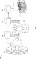
- FIGS. 1 and 2 show an energy storage system 100.
- the energy storage system 100 includes a wheel 102, a motor 104, a motor-generator 120, a flywheel 108, and a battery 114.
- the energy storage system 100 can store energy from the wheel 102 and the battery 114, and release energy to the wheel 102 and the battery 114 to serve as an energy buffer to meet peak energy requirements.
- the energy storage system 100 can be used with vehicles to efficiently store and use energy and increase the battery life of the battery 114.
- the energy storage system 100 can provide and receive kinetic energy from the wheel 102.
- the wheel 102 can be representative of any load that can provide and receive kinetic energy from the energy storage system 100.
- the wheel 102 is driven by a wheel motor 104.
- the wheel motor 104 can function as a generator to convert kinetic energy from the wheel 102 to electrical energy for use with the energy storage system 100.
- the wheel motor 104 can be a traction motor.
- the wheel motor 104 is a high voltage motor.
- the wheel motor 104 can be an AC permanent magnet synchronous motor.
- the wheel motor 104 can be high efficiency and provide high power density.
- the wheel motor 104 can be electrically connected to the motor-generator 120 via an AC/DC/AC converter 106.
- the AC/DC/AC converter 106 is a three-phase, four quadrant converter.
- the AC/DC/AC converter 106 can facilitate bidirectional power transfer to the wheel 102 and from the wheel 102.
- power flows to the wheel motor 104 and AC/DC/AC converter 106 operates as a rectifier at the motor-generator 120 side and as an inverter as the wheel motor 104 side as kinetic energy from the flywheel 108 is transferred as kinetic energy of the wheel 102.
- the AC/DC/AC converter 106 operates as a rectifier at the wheel motor 104 side and as an inverter at the motor-generator 120 side as kinetic energy from the wheel 102 is transferred to the flywheel 108 by facilitating generation operations of the wheel motor 104.
- the battery 114 can introduce stored chemical energy into the energy storage system 100.
- the battery 114 can further store and provide energy to the wheel 102.
- the battery 114 may provide energy, but may not provide adequate transient response for immediate power demands as may be required with certain applications, such as vehicles. Therefore, in certain embodiments, the battery 114 can provide energy to the flywheel 108 for use by the energy storage system 100 which may then be rapidly deployed as needed.
- the battery 114 can be representative of any suitable energy source.
- the battery 114 is electrically connected to the motor-generator 120 via a bidirectional DC/DC converter 112 and a bidirectional AC/DC converter 110.
- the DC/DC converter 112 controls output from the battery 114 to limit output current or alternatively boost battery 114 voltage. Further, the DC/DC converter 112 can be utilized to recharge the battery 114 by using energy from the flywheel 108.
- the AC/DC converter 110 can control the speed and torque of the flywheel 108 while the AC/DC converter functions as an inverter. Further, the AC/DC converter 110 can function as a rectifier as energy stored in the flywheel 108 is sent to the battery 114.
- the motor-generator 120 is connected to the flywheel 108 either directly, by a gearbox or by a linkage.
- the flywheel 108 can provide energy storage by storing and releasing kinetic energy to either the wheel motor 104 or the battery 114.
- the energy storage parameters of the flywheel 108 are determined by the moment of inertia and the rotational speed of the flywheel 108.
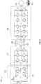
- the motor-generator 120 can receive electrical energy from the wheel motor 104 and the battery 114 to provide kinetic energy to the flywheel 108. Further the motor-generator 120 can provide electrical energy to the wheel motor 104 and the battery 104 from the kinetic energy of the flywheel 108. As shown in FIG. 2 , the motor-generator 120 can include a low voltage coil winding 130 and a high voltage coil winding 140 to allow electrical connections to both the low voltage/low power battery 114 and the high voltage/high power wheel motor 104 simultaneously. Advantageously, the motor-generator 120 can allow for the energy storage system 100 to operate at two voltage levels, similar to a traditional electrical transformer, by allowing energy to be introduced and removed by both the low voltage coil winding 130 and the high voltage coil winding 140. The motor-generator 120 can be used in any suitable application, including, but limited to vehicles such as hybrid or full electric vehicles.
- the low voltage coil winding 130 may experience voltage ranging from 6 to 48 VDC after rectification. In certain embodiments, the low voltage coil winding 130 may experience any suitable DC voltage after rectification. In the illustrated embodiment, the low voltage coil winding 130 is formed from a material and geometry to be suitable for use with the expected voltage and power. In certain embodiments, the high voltage coil winding 140 may experience voltage ranging from 100 to 1000 VDC after rectification. In certain embodiments, the high voltage coil winding 140 may experience any suitable DC voltage after rectification. In the illustrated embodiment, the high voltage coil winding 140 is formed from a material and geometry to be suitable for use with the expected voltage and power.
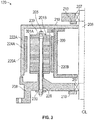
- the motor-generator 120 includes a double-sided stator 200 with a first stator pole 201A wound with a first stator winding 202A of a first channel 212A and a second stator pole 201B wound with a second stator winding 202B of a second channel 212B, where the first stator pole 201A and the second stator pole 201B are axially aligned with respect to a centerline CL of a shaft 206 of the motor-generator 120 and radially offset between a radially inner side 214 and a radially outer side 216 of the double-sided stator 200.
- the first and the second channels 212A, 212B are independently controllable to supply or receive a same voltage or two different voltages.
- the first and second stator poles 201A, 201B can be salient poles characterized as having a relatively large diameter and a shorter axial length.
- the motor-generator 120 is a radial-flux synchronous machine, where the first stator winding 202A and the second stator winding 202B are in magnetic communication.
- magnetic coupling between the first stator winding 202A and the second stator winding 202B functions as a transformer by facilitating a step up or step down of voltage via the magnetic coupling there between.
- the first stator winding 202A is depicted as radially outward of the second stator winding 202B, the designations can be reversed such that either the first stator winding 202A or the second stator winding 202B can be established as the low voltage coil winding 130 or the high voltage coil winding 140 of FIG. 2 .
- the motor-generator 120 also includes at least one rotor 218 radially disposed from the double-sided stator 200 with respect to the centerline CL of the motor-generator 120.
- the at least one rotor 218 includes a radially outer portion 220A disposed radially outward of the double-sided stator 200 and a radially inner portion 220B disposed radially inward of the double-sided stator 200 with respect to the centerline CL of the motor-generator 120.
- the radially outer portion 220A includes a first set of field generating elements 222A operable to establish electro-magnetic communication with the first channel 212A
- the radially inner portion 220B includes a second set of field generating elements 222B operable to establish electro-magnetic communication with the second channel 212B.
- the first and second sets of field generating elements 222A, 222B can be supported by rotor ferromagnetic cores 224A, 224B and implemented as permanent magnets or rotor field windings fed from brushless exciters (not depicted).
- Operating speed can be increased by controlling the motor-generator 120 in a field-weakening mode by varying a field current of an exciter that feeds either or both of the first and second sets of field generating elements 222A, 222B when rotor field windings are used.
- the double-sided stator 200 includes a ferromagnetic yoke 226 including a plurality of pairs of the first stator pole 201A and the second stator pole 201B.
- the ferromagnetic yoke 226 is coupled to a stator housing 208 by a plurality of fasteners 205 that are electrically isolated from the ferromagnetic yoke 226, for instance, by an insulating tube 228 and insulating washers/end caps 230.
- a radial dimension h ( FIG. 4 ) is sufficiently small (e.g., a few millimeters) to obtain high magnetic saturation.
- the highly-saturated ferromagnetic yoke 226 of thickness h behaves as a non-ferromagnetic material.
- the relative magnetic permeability can be lower than 10, i.e., ⁇ r ⁇ 10; otherwise, transformer action between a pair of the first stator winding 202A and the second stator winding 202B on opposite sides of the ferromagnetic yoke 226 can be deteriorated by leakage flux between neighboring poles of the ferromagnetic yoke 226.
- One or more bearings 207 can support the shaft 206 that drives rotation of the at least one rotor 218 with respect to the stator housing 208.
- One or more bearing covers 210 can be installed proximate to the one or more bearings 207.
- the at least one rotor 218 is coupled to the flywheel 108 (shown in FIG. 1 ) to send and receive kinetic energy therefrom.
- the mass of the at least one rotor 218 can be utilized or supplement the energy storage function of the flywheel 108.
- the at least one rotor 218 can be integrated with the flywheel 108. In other embodiments, the mass of the at least one rotor 218 can be utilized as the flywheel 108.
Landscapes
- Engineering & Computer Science (AREA)
- Power Engineering (AREA)
- Connection Of Motors, Electrical Generators, Mechanical Devices, And The Like (AREA)
- Electric Propulsion And Braking For Vehicles (AREA)
Abstract
Description
- The subject matter disclosed herein relates to motor-generators, and more particularly, to a motor-generator with a double-sided stator configured as a radial-flux synchronous machine.
- Flywheel energy storage systems can be used to store energy that may be typically wasted and release energy as needed. Flywheel energy storage systems may utilize supplemental energy storage to increase functionality of the storage system. Often, utilizing multiple sources of energy within a flywheel energy storage system may result in a motor-generator that is large, complex, and cost prohibitive.
- According to an embodiment, a motor-generator includes a double-sided stator having a first stator pole wound with a first stator winding of a first channel and a second stator pole wound with a second stator winding of a second channel. The first stator pole and the second stator pole are axially aligned with respect to a centerline of the motor-generator and radially offset between a radially inner side and a radially outer side of the double-sided stator. The motor-generator also includes at least one rotor radially disposed from the double-sided stator with respect to the centerline of the motor-generator.
- According to another embodiment, an energy storage system includes a flywheel and a motor-generator. The motor-generator includes a double-sided stator having a first stator pole wound with a first stator winding of a first channel and a second stator pole wound with a second stator winding of a second channel. The first stator pole and the second stator pole are axially aligned with respect to a centerline of the motor-generator and radially offset between a radially inner side and a radially outer side of the double-sided stator. The motor-generator also includes at least one rotor operably coupled to the flywheel. The at least one rotor is radially disposed from the double-sided stator with respect to the centerline of the motor-generator.
- Technical effects of embodiments include a motor-generator with independently controllable channels having energy flow between the channels on opposite poles of a double-sided stator.
- Other aspects, features, and techniques of the embodiments will become more apparent from the following description taken in conjunction with the drawings.
- The subject matter is particularly pointed out and distinctly claimed in the claims at the conclusion of the specification. The foregoing and other features, and advantages of the embodiments are apparent from the following detailed description taken in conjunction with the accompanying drawings in which like elements are numbered alike in the FIGURES:
-
FIG. 1 is a schematic view of one embodiment of an energy storage system; -
FIG. 2 is an electrical diagram view of the energy storage system ofFIG. 1 ; -
FIG. 3 is a cross sectional view of an axial portion of an embodiment of a motor-generator for use with the energy storage system ofFIG. 1 ; and -
FIG. 4 is a cross sectional view of a radial portion of an embodiment of a motor-generator for use with the energy storage system ofFIG. 1 . - Referring now to the drawings,
FIGS. 1 and2 show anenergy storage system 100. In the illustrated embodiment, theenergy storage system 100 includes awheel 102, amotor 104, a motor-generator 120, aflywheel 108, and abattery 114. In the illustrated embodiment, theenergy storage system 100 can store energy from thewheel 102 and thebattery 114, and release energy to thewheel 102 and thebattery 114 to serve as an energy buffer to meet peak energy requirements. Advantageously, theenergy storage system 100 can be used with vehicles to efficiently store and use energy and increase the battery life of thebattery 114. - In the illustrated embodiment, the
energy storage system 100 can provide and receive kinetic energy from thewheel 102. In other embodiments, thewheel 102 can be representative of any load that can provide and receive kinetic energy from theenergy storage system 100. In the illustrated embodiment, thewheel 102 is driven by awheel motor 104. Further, thewheel motor 104 can function as a generator to convert kinetic energy from thewheel 102 to electrical energy for use with theenergy storage system 100. In certain embodiments, thewheel motor 104 can be a traction motor. In the illustrated embodiment, thewheel motor 104 is a high voltage motor. Further, thewheel motor 104 can be an AC permanent magnet synchronous motor. Advantageously, thewheel motor 104 can be high efficiency and provide high power density. - In the illustrated embodiment, the
wheel motor 104 can be electrically connected to the motor-generator 120 via an AC/DC/AC converter 106. In certain embodiments, the AC/DC/AC converter 106 is a three-phase, four quadrant converter. In the illustrated embodiment, the AC/DC/AC converter 106 can facilitate bidirectional power transfer to thewheel 102 and from thewheel 102. During a drive mode, power flows to thewheel motor 104 and AC/DC/ACconverter 106 operates as a rectifier at the motor-generator 120 side and as an inverter as thewheel motor 104 side as kinetic energy from theflywheel 108 is transferred as kinetic energy of thewheel 102. During braking or other regenerative operations, the AC/DC/AC converter 106 operates as a rectifier at thewheel motor 104 side and as an inverter at the motor-generator 120 side as kinetic energy from thewheel 102 is transferred to theflywheel 108 by facilitating generation operations of thewheel motor 104. - In the illustrated embodiment, the
battery 114 can introduce stored chemical energy into theenergy storage system 100. Thebattery 114 can further store and provide energy to thewheel 102. In certain embodiments, thebattery 114 may provide energy, but may not provide adequate transient response for immediate power demands as may be required with certain applications, such as vehicles. Therefore, in certain embodiments, thebattery 114 can provide energy to theflywheel 108 for use by theenergy storage system 100 which may then be rapidly deployed as needed. In the illustrated embodiment, thebattery 114 can be representative of any suitable energy source. - In the illustrated embodiment, the
battery 114 is electrically connected to the motor-generator 120 via a bidirectional DC/DC converter 112 and a bidirectional AC/DC converter 110. In the illustrated embodiment, the DC/DC converter 112 controls output from thebattery 114 to limit output current or alternatively boostbattery 114 voltage. Further, the DC/DC converter 112 can be utilized to recharge thebattery 114 by using energy from theflywheel 108. In the illustrated embodiment, the AC/DC converter 110 can control the speed and torque of theflywheel 108 while the AC/DC converter functions as an inverter. Further, the AC/DC converter 110 can function as a rectifier as energy stored in theflywheel 108 is sent to thebattery 114. - In the illustrated embodiment, the motor-
generator 120 is connected to theflywheel 108 either directly, by a gearbox or by a linkage. Theflywheel 108 can provide energy storage by storing and releasing kinetic energy to either thewheel motor 104 or thebattery 114. The energy storage parameters of theflywheel 108 are determined by the moment of inertia and the rotational speed of theflywheel 108. - The motor-
generator 120 can receive electrical energy from thewheel motor 104 and thebattery 114 to provide kinetic energy to theflywheel 108. Further the motor-generator 120 can provide electrical energy to thewheel motor 104 and thebattery 104 from the kinetic energy of theflywheel 108. As shown inFIG. 2 , the motor-generator 120 can include a low voltage coil winding 130 and a high voltage coil winding 140 to allow electrical connections to both the low voltage/low power battery 114 and the high voltage/highpower wheel motor 104 simultaneously. Advantageously, the motor-generator 120 can allow for theenergy storage system 100 to operate at two voltage levels, similar to a traditional electrical transformer, by allowing energy to be introduced and removed by both the low voltage coil winding 130 and the high voltage coil winding 140. The motor-generator 120 can be used in any suitable application, including, but limited to vehicles such as hybrid or full electric vehicles. - In certain embodiments, the low voltage coil winding 130 may experience voltage ranging from 6 to 48 VDC after rectification. In certain embodiments, the low voltage coil winding 130 may experience any suitable DC voltage after rectification. In the illustrated embodiment, the low voltage coil winding 130 is formed from a material and geometry to be suitable for use with the expected voltage and power. In certain embodiments, the high voltage coil winding 140 may experience voltage ranging from 100 to 1000 VDC after rectification. In certain embodiments, the high voltage coil winding 140 may experience any suitable DC voltage after rectification. In the illustrated embodiment, the high voltage coil winding 140 is formed from a material and geometry to be suitable for use with the expected voltage and power.
- Referring to
FIGS. 3 and4 cross sections of the motor-generator 120 are shown according to an embodiment. In the illustrated embodiment, the motor-generator 120 includes a double-sided stator 200 with afirst stator pole 201A wound with a first stator winding 202A of afirst channel 212A and asecond stator pole 201B wound with a second stator winding 202B of asecond channel 212B, where thefirst stator pole 201A and thesecond stator pole 201B are axially aligned with respect to a centerline CL of ashaft 206 of the motor-generator 120 and radially offset between a radiallyinner side 214 and a radiallyouter side 216 of the double-sided stator 200. The first and thesecond channels second stator poles - The motor-
generator 120 is a radial-flux synchronous machine, where the first stator winding 202A and the second stator winding 202B are in magnetic communication. In certain embodiments, magnetic coupling between the first stator winding 202A and the second stator winding 202B functions as a transformer by facilitating a step up or step down of voltage via the magnetic coupling there between. Although the first stator winding 202A is depicted as radially outward of the second stator winding 202B, the designations can be reversed such that either the first stator winding 202A or the second stator winding 202B can be established as the low voltage coil winding 130 or the high voltage coil winding 140 ofFIG. 2 . - The motor-
generator 120 also includes at least onerotor 218 radially disposed from the double-sided stator 200 with respect to the centerline CL of the motor-generator 120. The at least onerotor 218 includes a radiallyouter portion 220A disposed radially outward of the double-sided stator 200 and a radiallyinner portion 220B disposed radially inward of the double-sided stator 200 with respect to the centerline CL of the motor-generator 120. The radiallyouter portion 220A includes a first set offield generating elements 222A operable to establish electro-magnetic communication with thefirst channel 212A, and the radiallyinner portion 220B includes a second set offield generating elements 222B operable to establish electro-magnetic communication with thesecond channel 212B. The first and second sets offield generating elements ferromagnetic cores generator 120 in a field-weakening mode by varying a field current of an exciter that feeds either or both of the first and second sets offield generating elements - The double-
sided stator 200 includes aferromagnetic yoke 226 including a plurality of pairs of thefirst stator pole 201A and thesecond stator pole 201B. Theferromagnetic yoke 226 is coupled to astator housing 208 by a plurality offasteners 205 that are electrically isolated from theferromagnetic yoke 226, for instance, by an insulatingtube 228 and insulating washers/end caps 230. To obtain good magnetic coupling between two coils belonging to two different opposite windings, sizing of the double-sided stator 200 is constrained. A radial dimension h (FIG. 4 ) is sufficiently small (e.g., a few millimeters) to obtain high magnetic saturation. The highly-saturatedferromagnetic yoke 226 of thickness h behaves as a non-ferromagnetic material. The relative magnetic permeability can be lower than 10, i.e., µr ≤ 10; otherwise, transformer action between a pair of the first stator winding 202A and the second stator winding 202B on opposite sides of theferromagnetic yoke 226 can be deteriorated by leakage flux between neighboring poles of theferromagnetic yoke 226. - One or
more bearings 207 can support theshaft 206 that drives rotation of the at least onerotor 218 with respect to thestator housing 208. One or more bearing covers 210 can be installed proximate to the one ormore bearings 207. In the illustrated embodiment, the at least onerotor 218 is coupled to the flywheel 108 (shown inFIG. 1 ) to send and receive kinetic energy therefrom. In certain embodiments, the mass of the at least onerotor 218 can be utilized or supplement the energy storage function of theflywheel 108. In certain embodiments, the at least onerotor 218 can be integrated with theflywheel 108. In other embodiments, the mass of the at least onerotor 218 can be utilized as theflywheel 108. - The terminology used herein is for the purpose of describing particular embodiments only and is not intended to be limiting of the embodiments. While the description of the present embodiments has been presented for purposes of illustration and description, it is not intended to be exhaustive or limited to the embodiments in the form disclosed. Many modifications, variations, alterations, substitutions or equivalent arrangement not hereto described will be apparent to those of ordinary skill in the art without departing from the scope of the embodiments. Additionally, while various embodiments have been described, it is to be understood that aspects may include only some of the described embodiments. Accordingly, the embodiments are not to be seen as limited by the foregoing description, but are only limited by the scope of the appended claims.
Claims (15)
- A motor-generator (120), comprising:a double-sided stator (200) comprising a first stator pole (201A) wound with a first stator winding (202A) of a first channel (212A) and a second stator pole (201B) wound with a second stator winding (202B) of a second channel (212B), wherein the first stator pole (201 A) and the second stator pole (201B) are axially aligned with respect to a centerline of the motor-generator (120) and radially offset between a radially inner side and a radially outer side of the double-sided stator (200); andat least one rotor (218) radially disposed from the double-sided stator (200) with respect to the centerline of the motor-generator.
- The motor-generator of claim 1, wherein the first and second stator poles (201A, 201B) are salient poles.
- The motor-generator of claim 1, wherein the first stator winding (202A) is a first concentrated parameter stator winding and the second stator winding (202B) is a second concentrated parameter stator winding.
- The motor-generator of claim 1, wherein the motor-generator (120) is a radial-flux synchronous machine.
- The motor-generator of claim 1, wherein the first and the second channels (212A, 212B) are independently controllable to supply or receive a same voltage or two different voltages.
- The motor-generator of claim 1, wherein the first stator winding (202A) and the second stator winding (202B) are in magnetic communication.
- The motor-generator of claim 1, wherein the double-sided stator (200) comprises a ferromagnetic yoke (226) comprising a plurality of pairs of the first stator pole and the second stator pole.
- The motor-generator of claim 7, wherein the ferromagnetic yoke (226) is coupled to a stator housing by a plurality of fasteners that are electrically isolated from the ferromagnetic yoke.
- The motor-generator of claim 1, wherein the at least one rotor (218) comprises a radially outer portion disposed radially outward of the double-sided stator and a radially inner portion disposed radially inward of the double-sided stator with respect to the centerline of the motor-generator.
- The motor-generator of claim 9, wherein the radially outer portion comprises a first set of field generating elements operable to establish electro-magnetic communication with the first channel, and the radially inner portion comprises a second set of field generating elements operable to establish electro-magnetic communication with the second channel.
- An energy storage system, comprising:a flywheel; anda motor-generator, comprising:a double-sided stator comprising a first stator pole wound with a first stator winding of a first channel and a second stator pole wound with a second stator winding of a second channel, wherein the first stator pole and the second stator pole are axially aligned with respect to a centerline of the motor-generator and radially offset between a radially inner side and a radially outer side of the double-sided stator; andat least one rotor operably coupled to the flywheel, wherein the at least one rotor is radially disposed from the double-sided stator with respect to the centerline of the motor-generator.
- The energy storage system of claim 11, wherein the flywheel is integrally formed with the at least one rotor.
- The energy storage system of claim 11, wherein the first and second stator poles are salient poles, the first stator winding is a first concentrated parameter stator winding, and the second stator winding is a second concentrated parameter stator winding.
- The energy storage system of claim 11, wherein the first and the second channels are independently controllable to supply or receive a same voltage or two different voltages comprising a lower voltage and a higher voltage.
- The energy storage system of claim 14, wherein a low-voltage coil winding of the motor-generator establishes an electrical connection with the lower voltage, and a high-voltage coil winding of the motor-generator establishes an electrical connection with the higher voltage.
Applications Claiming Priority (1)
| Application Number | Priority Date | Filing Date | Title |
|---|---|---|---|
| US15/224,753 US10381886B2 (en) | 2016-08-01 | 2016-08-01 | Motor-generator with radial-flux double-sided stator |
Publications (2)
| Publication Number | Publication Date |
|---|---|
| EP3280035A1 true EP3280035A1 (en) | 2018-02-07 |
| EP3280035B1 EP3280035B1 (en) | 2021-06-16 |
Family
ID=59399301
Family Applications (1)
| Application Number | Title | Priority Date | Filing Date |
|---|---|---|---|
| EP17182918.7A Active EP3280035B1 (en) | 2016-08-01 | 2017-07-25 | Motor-generator with radial-flux double-sided stator |
Country Status (2)
| Country | Link |
|---|---|
| US (1) | US10381886B2 (en) |
| EP (1) | EP3280035B1 (en) |
Cited By (1)
| Publication number | Priority date | Publication date | Assignee | Title |
|---|---|---|---|---|
| US10778061B2 (en) | 2018-11-07 | 2020-09-15 | Industrial Technology Research Institute | Flywheel energy storage system |
Families Citing this family (8)
| Publication number | Priority date | Publication date | Assignee | Title |
|---|---|---|---|---|
| US10270305B2 (en) | 2015-12-07 | 2019-04-23 | Hamilton Sundstrand Corporation | Motor-generator with multiple stator windings |
| KR20210034071A (en) * | 2018-07-27 | 2021-03-29 | 에어본 모터 워크스 인코포레이티드 | Thrust generation split flywheel gyroscope method and apparatus |
| CN112912691A (en) | 2018-08-26 | 2021-06-04 | 航空电机工程有限公司 | Electromagnetic gyro stabilized propulsion system method and device |
| KR20210116532A (en) | 2019-01-20 | 2021-09-27 | 에어본 모터스, 엘엘씨 | Medical ballast harness method and device |
| US12546287B2 (en) | 2020-02-28 | 2026-02-10 | Airborne Motorworks Inc. | Sound vibration and friction limiting turbine generator gyroscope method and apparatus |
| US11923733B2 (en) * | 2020-08-28 | 2024-03-05 | Quantentech Limited | High efficiency high density motor and generator with multiple airgaps |
| CN120834690A (en) * | 2024-04-17 | 2025-10-24 | 通用汽车环球科技运作有限责任公司 | Variable cross-section conductor for reducing AC losses in axial flux, radial flux, and skew motors |
| US20250330059A1 (en) * | 2024-04-19 | 2025-10-23 | Feng-Tien Chen | Rotating electrical machine and operating method thereof |
Citations (4)
| Publication number | Priority date | Publication date | Assignee | Title |
|---|---|---|---|---|
| US6828710B1 (en) * | 2002-02-19 | 2004-12-07 | Christopher W. Gabrys | Airgap armature |
| EP1931015A2 (en) * | 2006-12-07 | 2008-06-11 | General Electric Company | Double-sided starter-generator for aircraft |
| US20120299401A1 (en) * | 2008-05-21 | 2012-11-29 | Bryan Prucher | Motor/generator structure |
| US20130033136A1 (en) * | 2011-08-03 | 2013-02-07 | Mcmullen Patrick T | Electric Machine with Inner Magnet Hub |
Family Cites Families (21)
| Publication number | Priority date | Publication date | Assignee | Title |
|---|---|---|---|---|
| US5396140A (en) | 1993-05-28 | 1995-03-07 | Satcon Technology, Corp. | Parallel air gap serial flux A.C. electrical machine |
| US5568023A (en) * | 1994-05-18 | 1996-10-22 | Grayer; William | Electric power train control |
| FR2742939B1 (en) | 1995-12-21 | 1998-03-06 | Jeumont Ind | MODULAR DISCOID ELECTRIC MACHINE |
| DE19715468C1 (en) | 1997-04-14 | 1998-10-01 | Piller Gmbh | System for stabilizing a power supply network |
| US5907199A (en) | 1997-10-09 | 1999-05-25 | Ut Automotive Dearborn, Inc. | Electric motor providing multi-directional output |
| JP3561248B2 (en) | 2001-09-17 | 2004-09-02 | 日本サーボ株式会社 | Flat multi-phase permanent magnet type stepping motor and its excitation circuit |
| SE524541C2 (en) | 2002-11-18 | 2004-08-24 | Uppsala Power Man Consultants | Power storage systems and vehicles fitted with such |
| US8030787B2 (en) | 2003-06-06 | 2011-10-04 | Beaver Aerospace And Defense, Inc. | Mbackup flywheel power supply |
| JP4876661B2 (en) | 2006-03-24 | 2012-02-15 | 株式会社デンソー | Electric generator for vehicle |
| JP2008086064A (en) * | 2006-09-26 | 2008-04-10 | Jtekt Corp | Brushless motor |
| US7880424B2 (en) | 2006-09-28 | 2011-02-01 | Denso Corporation | Rotary electric apparatus having rotor with field winding inducing current therethrough for generating magnetic field |
| CN101227136A (en) | 2007-01-16 | 2008-07-23 | 林冈嵚 | Independent self-free type integral compound excitation automatic ring-gathering synchronous magnetic energy power generator |
| US8847464B2 (en) | 2008-06-12 | 2014-09-30 | General Electric Company | Electrical machine with improved stator flux pattern across a rotor that permits higher torque density |
| US8358111B2 (en) | 2009-12-03 | 2013-01-22 | Hamilton Sundstrand Corporation | Architecture for dual source electric power generating system |
| US20120323427A1 (en) * | 2010-03-30 | 2012-12-20 | Toyota Jidosha Kabushiki Kaisha | Vehicle control apparatus and vehicle control method |
| US9457671B2 (en) * | 2010-05-14 | 2016-10-04 | Carl Manganaro | Drive system for a motor vehicle |
| CN102931788A (en) | 2011-12-16 | 2013-02-13 | 沈坤元 | Disc compound multi-combination three-dimensional permanent magnet motor |
| US8699251B2 (en) | 2012-04-24 | 2014-04-15 | Hamilton Sundstrand Corporation | Direct current generating, management and distribution system |
| US20140191606A1 (en) | 2013-01-10 | 2014-07-10 | Hamilton Sundstrand Corporation | Multi-channel wound-field synchronous machine |
| US8912765B2 (en) | 2013-03-15 | 2014-12-16 | Hamilton Sundstrand Corporation | EPGS architecture with multi-channel synchronous generator and common unregulated PMG exciter |
| US10270305B2 (en) | 2015-12-07 | 2019-04-23 | Hamilton Sundstrand Corporation | Motor-generator with multiple stator windings |
-
2016
- 2016-08-01 US US15/224,753 patent/US10381886B2/en active Active
-
2017
- 2017-07-25 EP EP17182918.7A patent/EP3280035B1/en active Active
Patent Citations (4)
| Publication number | Priority date | Publication date | Assignee | Title |
|---|---|---|---|---|
| US6828710B1 (en) * | 2002-02-19 | 2004-12-07 | Christopher W. Gabrys | Airgap armature |
| EP1931015A2 (en) * | 2006-12-07 | 2008-06-11 | General Electric Company | Double-sided starter-generator for aircraft |
| US20120299401A1 (en) * | 2008-05-21 | 2012-11-29 | Bryan Prucher | Motor/generator structure |
| US20130033136A1 (en) * | 2011-08-03 | 2013-02-07 | Mcmullen Patrick T | Electric Machine with Inner Magnet Hub |
Cited By (1)
| Publication number | Priority date | Publication date | Assignee | Title |
|---|---|---|---|---|
| US10778061B2 (en) | 2018-11-07 | 2020-09-15 | Industrial Technology Research Institute | Flywheel energy storage system |
Also Published As
| Publication number | Publication date |
|---|---|
| EP3280035B1 (en) | 2021-06-16 |
| US10381886B2 (en) | 2019-08-13 |
| US20180034353A1 (en) | 2018-02-01 |
Similar Documents
| Publication | Publication Date | Title |
|---|---|---|
| EP3280035B1 (en) | Motor-generator with radial-flux double-sided stator | |
| EP3179614B1 (en) | Motor-generator with multiple stator windings | |
| US9979266B2 (en) | Electrical rotating machines | |
| US8040010B2 (en) | Permanent magnet type generator and hybrid vehicle using the same | |
| US9935532B2 (en) | Double-rotor type electrical rotating machines | |
| US7635039B2 (en) | Series hybrid electric vehicle | |
| EP2601733B1 (en) | Rotating electromechanical converter | |
| US9318937B2 (en) | Flux controlled PM electric machine rotor | |
| CN101903203A (en) | A method of operating an electromechnical converter, a controller and a computer program product | |
| CN103701288A (en) | Multi-winding motor | |
| CN110545021B (en) | Mixed excitation multi-phase reluctance motor and power generation system | |
| US8310115B2 (en) | High power-density, high efficiency, non-permanent magnet electric machine | |
| CN101299553A (en) | A full-cycle power generation operation control method for a bearingless switched reluctance motor | |
| CN102377300A (en) | Double-stator single-rotor rare earth permanent magnet motor | |
| CN106341013A (en) | Permanent magnet-magnetic resistance radial magnetic-flux compound double-rotor motor | |
| CN102480199A (en) | Hybrid excitation brushless single phase synchronous generator with novel structure | |
| CN210405045U (en) | Axial Parallel Compound Motor | |
| CN109639035A (en) | Motor and the double-deck accumulated energy flywheel based on two-level rotor structure | |
| CN107565788A (en) | A kind of pole-changing DC starter-generator | |
| CN102480198A (en) | Permanent magnet type alternating-current synchronous generator with novel structure | |
| WO2016042335A1 (en) | Energy storage system and control method thereof | |
| CN101882901A (en) | Double-magnetic ring induction type magnetic energy electric generator | |
| CN108429421A (en) | Hybrid excitation motor for new energy automobile | |
| KR101498360B1 (en) | Generator | |
| CN213341773U (en) | Generator, power generation system and automobile |
Legal Events
| Date | Code | Title | Description |
|---|---|---|---|
| PUAI | Public reference made under article 153(3) epc to a published international application that has entered the european phase |
Free format text: ORIGINAL CODE: 0009012 |
|
| STAA | Information on the status of an ep patent application or granted ep patent |
Free format text: STATUS: THE APPLICATION HAS BEEN PUBLISHED |
|
| AK | Designated contracting states |
Kind code of ref document: A1 Designated state(s): AL AT BE BG CH CY CZ DE DK EE ES FI FR GB GR HR HU IE IS IT LI LT LU LV MC MK MT NL NO PL PT RO RS SE SI SK SM TR |
|
| AX | Request for extension of the european patent |
Extension state: BA ME |
|
| STAA | Information on the status of an ep patent application or granted ep patent |
Free format text: STATUS: REQUEST FOR EXAMINATION WAS MADE |
|
| 17P | Request for examination filed |
Effective date: 20180807 |
|
| RBV | Designated contracting states (corrected) |
Designated state(s): AL AT BE BG CH CY CZ DE DK EE ES FI FR GB GR HR HU IE IS IT LI LT LU LV MC MK MT NL NO PL PT RO RS SE SI SK SM TR |
|
| GRAP | Despatch of communication of intention to grant a patent |
Free format text: ORIGINAL CODE: EPIDOSNIGR1 |
|
| STAA | Information on the status of an ep patent application or granted ep patent |
Free format text: STATUS: GRANT OF PATENT IS INTENDED |
|
| INTG | Intention to grant announced |
Effective date: 20210118 |
|
| RIC1 | Information provided on ipc code assigned before grant |
Ipc: H02K 1/14 20060101ALN20201221BHEP Ipc: H02K 21/48 20060101ALI20201221BHEP Ipc: H02K 7/02 20060101AFI20201221BHEP Ipc: H02K 16/02 20060101ALI20201221BHEP Ipc: H02K 21/12 20060101ALN20201221BHEP |
|
| GRAS | Grant fee paid |
Free format text: ORIGINAL CODE: EPIDOSNIGR3 |
|
| GRAA | (expected) grant |
Free format text: ORIGINAL CODE: 0009210 |
|
| STAA | Information on the status of an ep patent application or granted ep patent |
Free format text: STATUS: THE PATENT HAS BEEN GRANTED |
|
| AK | Designated contracting states |
Kind code of ref document: B1 Designated state(s): AL AT BE BG CH CY CZ DE DK EE ES FI FR GB GR HR HU IE IS IT LI LT LU LV MC MK MT NL NO PL PT RO RS SE SI SK SM TR |
|
| REG | Reference to a national code |
Ref country code: GB Ref legal event code: FG4D |
|
| REG | Reference to a national code |
Ref country code: CH Ref legal event code: EP |
|
| REG | Reference to a national code |
Ref country code: DE Ref legal event code: R096 Ref document number: 602017040274 Country of ref document: DE |
|
| REG | Reference to a national code |
Ref country code: AT Ref legal event code: REF Ref document number: 1403156 Country of ref document: AT Kind code of ref document: T Effective date: 20210715 |
|
| REG | Reference to a national code |
Ref country code: IE Ref legal event code: FG4D |
|
| REG | Reference to a national code |
Ref country code: LT Ref legal event code: MG9D |
|
| PG25 | Lapsed in a contracting state [announced via postgrant information from national office to epo] |
Ref country code: HR Free format text: LAPSE BECAUSE OF FAILURE TO SUBMIT A TRANSLATION OF THE DESCRIPTION OR TO PAY THE FEE WITHIN THE PRESCRIBED TIME-LIMIT Effective date: 20210616 Ref country code: BG Free format text: LAPSE BECAUSE OF FAILURE TO SUBMIT A TRANSLATION OF THE DESCRIPTION OR TO PAY THE FEE WITHIN THE PRESCRIBED TIME-LIMIT Effective date: 20210916 Ref country code: FI Free format text: LAPSE BECAUSE OF FAILURE TO SUBMIT A TRANSLATION OF THE DESCRIPTION OR TO PAY THE FEE WITHIN THE PRESCRIBED TIME-LIMIT Effective date: 20210616 Ref country code: LT Free format text: LAPSE BECAUSE OF FAILURE TO SUBMIT A TRANSLATION OF THE DESCRIPTION OR TO PAY THE FEE WITHIN THE PRESCRIBED TIME-LIMIT Effective date: 20210616 |
|
| REG | Reference to a national code |
Ref country code: AT Ref legal event code: MK05 Ref document number: 1403156 Country of ref document: AT Kind code of ref document: T Effective date: 20210616 |
|
| REG | Reference to a national code |
Ref country code: NL Ref legal event code: MP Effective date: 20210616 |
|
| PG25 | Lapsed in a contracting state [announced via postgrant information from national office to epo] |
Ref country code: NO Free format text: LAPSE BECAUSE OF FAILURE TO SUBMIT A TRANSLATION OF THE DESCRIPTION OR TO PAY THE FEE WITHIN THE PRESCRIBED TIME-LIMIT Effective date: 20210916 Ref country code: SE Free format text: LAPSE BECAUSE OF FAILURE TO SUBMIT A TRANSLATION OF THE DESCRIPTION OR TO PAY THE FEE WITHIN THE PRESCRIBED TIME-LIMIT Effective date: 20210616 Ref country code: RS Free format text: LAPSE BECAUSE OF FAILURE TO SUBMIT A TRANSLATION OF THE DESCRIPTION OR TO PAY THE FEE WITHIN THE PRESCRIBED TIME-LIMIT Effective date: 20210616 Ref country code: GR Free format text: LAPSE BECAUSE OF FAILURE TO SUBMIT A TRANSLATION OF THE DESCRIPTION OR TO PAY THE FEE WITHIN THE PRESCRIBED TIME-LIMIT Effective date: 20210917 Ref country code: LV Free format text: LAPSE BECAUSE OF FAILURE TO SUBMIT A TRANSLATION OF THE DESCRIPTION OR TO PAY THE FEE WITHIN THE PRESCRIBED TIME-LIMIT Effective date: 20210616 |
|
| PG25 | Lapsed in a contracting state [announced via postgrant information from national office to epo] |
Ref country code: ES Free format text: LAPSE BECAUSE OF FAILURE TO SUBMIT A TRANSLATION OF THE DESCRIPTION OR TO PAY THE FEE WITHIN THE PRESCRIBED TIME-LIMIT Effective date: 20210616 Ref country code: RO Free format text: LAPSE BECAUSE OF FAILURE TO SUBMIT A TRANSLATION OF THE DESCRIPTION OR TO PAY THE FEE WITHIN THE PRESCRIBED TIME-LIMIT Effective date: 20210616 Ref country code: NL Free format text: LAPSE BECAUSE OF FAILURE TO SUBMIT A TRANSLATION OF THE DESCRIPTION OR TO PAY THE FEE WITHIN THE PRESCRIBED TIME-LIMIT Effective date: 20210616 Ref country code: PT Free format text: LAPSE BECAUSE OF FAILURE TO SUBMIT A TRANSLATION OF THE DESCRIPTION OR TO PAY THE FEE WITHIN THE PRESCRIBED TIME-LIMIT Effective date: 20211018 Ref country code: EE Free format text: LAPSE BECAUSE OF FAILURE TO SUBMIT A TRANSLATION OF THE DESCRIPTION OR TO PAY THE FEE WITHIN THE PRESCRIBED TIME-LIMIT Effective date: 20210616 Ref country code: CZ Free format text: LAPSE BECAUSE OF FAILURE TO SUBMIT A TRANSLATION OF THE DESCRIPTION OR TO PAY THE FEE WITHIN THE PRESCRIBED TIME-LIMIT Effective date: 20210616 Ref country code: AT Free format text: LAPSE BECAUSE OF FAILURE TO SUBMIT A TRANSLATION OF THE DESCRIPTION OR TO PAY THE FEE WITHIN THE PRESCRIBED TIME-LIMIT Effective date: 20210616 Ref country code: SM Free format text: LAPSE BECAUSE OF FAILURE TO SUBMIT A TRANSLATION OF THE DESCRIPTION OR TO PAY THE FEE WITHIN THE PRESCRIBED TIME-LIMIT Effective date: 20210616 Ref country code: SK Free format text: LAPSE BECAUSE OF FAILURE TO SUBMIT A TRANSLATION OF THE DESCRIPTION OR TO PAY THE FEE WITHIN THE PRESCRIBED TIME-LIMIT Effective date: 20210616 |
|
| REG | Reference to a national code |
Ref country code: DE Ref legal event code: R119 Ref document number: 602017040274 Country of ref document: DE |
|
| PG25 | Lapsed in a contracting state [announced via postgrant information from national office to epo] |
Ref country code: PL Free format text: LAPSE BECAUSE OF FAILURE TO SUBMIT A TRANSLATION OF THE DESCRIPTION OR TO PAY THE FEE WITHIN THE PRESCRIBED TIME-LIMIT Effective date: 20210616 |
|
| REG | Reference to a national code |
Ref country code: CH Ref legal event code: PL |
|
| PG25 | Lapsed in a contracting state [announced via postgrant information from national office to epo] |
Ref country code: MC Free format text: LAPSE BECAUSE OF FAILURE TO SUBMIT A TRANSLATION OF THE DESCRIPTION OR TO PAY THE FEE WITHIN THE PRESCRIBED TIME-LIMIT Effective date: 20210616 |
|
| REG | Reference to a national code |
Ref country code: BE Ref legal event code: MM Effective date: 20210731 |
|
| PLBE | No opposition filed within time limit |
Free format text: ORIGINAL CODE: 0009261 |
|
| STAA | Information on the status of an ep patent application or granted ep patent |
Free format text: STATUS: NO OPPOSITION FILED WITHIN TIME LIMIT |
|
| PG25 | Lapsed in a contracting state [announced via postgrant information from national office to epo] |
Ref country code: LI Free format text: LAPSE BECAUSE OF NON-PAYMENT OF DUE FEES Effective date: 20210731 Ref country code: DK Free format text: LAPSE BECAUSE OF FAILURE TO SUBMIT A TRANSLATION OF THE DESCRIPTION OR TO PAY THE FEE WITHIN THE PRESCRIBED TIME-LIMIT Effective date: 20210616 Ref country code: DE Free format text: LAPSE BECAUSE OF NON-PAYMENT OF DUE FEES Effective date: 20220201 Ref country code: CH Free format text: LAPSE BECAUSE OF NON-PAYMENT OF DUE FEES Effective date: 20210731 |
|
| 26N | No opposition filed |
Effective date: 20220317 |
|
| PG25 | Lapsed in a contracting state [announced via postgrant information from national office to epo] |
Ref country code: LU Free format text: LAPSE BECAUSE OF NON-PAYMENT OF DUE FEES Effective date: 20210725 Ref country code: AL Free format text: LAPSE BECAUSE OF FAILURE TO SUBMIT A TRANSLATION OF THE DESCRIPTION OR TO PAY THE FEE WITHIN THE PRESCRIBED TIME-LIMIT Effective date: 20210616 |
|
| PG25 | Lapsed in a contracting state [announced via postgrant information from national office to epo] |
Ref country code: IT Free format text: LAPSE BECAUSE OF FAILURE TO SUBMIT A TRANSLATION OF THE DESCRIPTION OR TO PAY THE FEE WITHIN THE PRESCRIBED TIME-LIMIT Effective date: 20210616 Ref country code: IE Free format text: LAPSE BECAUSE OF NON-PAYMENT OF DUE FEES Effective date: 20210725 Ref country code: BE Free format text: LAPSE BECAUSE OF NON-PAYMENT OF DUE FEES Effective date: 20210731 |
|
| PG25 | Lapsed in a contracting state [announced via postgrant information from national office to epo] |
Ref country code: HU Free format text: LAPSE BECAUSE OF FAILURE TO SUBMIT A TRANSLATION OF THE DESCRIPTION OR TO PAY THE FEE WITHIN THE PRESCRIBED TIME-LIMIT; INVALID AB INITIO Effective date: 20170725 |
|
| P01 | Opt-out of the competence of the unified patent court (upc) registered |
Effective date: 20230522 |
|
| PG25 | Lapsed in a contracting state [announced via postgrant information from national office to epo] |
Ref country code: CY Free format text: LAPSE BECAUSE OF FAILURE TO SUBMIT A TRANSLATION OF THE DESCRIPTION OR TO PAY THE FEE WITHIN THE PRESCRIBED TIME-LIMIT Effective date: 20210616 |
|
| PG25 | Lapsed in a contracting state [announced via postgrant information from national office to epo] |
Ref country code: MK Free format text: LAPSE BECAUSE OF FAILURE TO SUBMIT A TRANSLATION OF THE DESCRIPTION OR TO PAY THE FEE WITHIN THE PRESCRIBED TIME-LIMIT Effective date: 20210616 |
|
| PG25 | Lapsed in a contracting state [announced via postgrant information from national office to epo] |
Ref country code: MT Free format text: LAPSE BECAUSE OF FAILURE TO SUBMIT A TRANSLATION OF THE DESCRIPTION OR TO PAY THE FEE WITHIN THE PRESCRIBED TIME-LIMIT Effective date: 20210616 |
|
| PGFP | Annual fee paid to national office [announced via postgrant information from national office to epo] |
Ref country code: GB Payment date: 20250619 Year of fee payment: 9 |
|
| PGFP | Annual fee paid to national office [announced via postgrant information from national office to epo] |
Ref country code: FR Payment date: 20250620 Year of fee payment: 9 |
|
| PG25 | Lapsed in a contracting state [announced via postgrant information from national office to epo] |
Ref country code: TR Free format text: LAPSE BECAUSE OF FAILURE TO SUBMIT A TRANSLATION OF THE DESCRIPTION OR TO PAY THE FEE WITHIN THE PRESCRIBED TIME-LIMIT Effective date: 20210616 |